EP4417421A2 - Sheet separation device and laminating system - Google Patents
Sheet separation device and laminating system Download PDFInfo
- Publication number
- EP4417421A2 EP4417421A2 EP24153102.9A EP24153102A EP4417421A2 EP 4417421 A2 EP4417421 A2 EP 4417421A2 EP 24153102 A EP24153102 A EP 24153102A EP 4417421 A2 EP4417421 A2 EP 4417421A2
- Authority
- EP
- European Patent Office
- Prior art keywords
- sheet
- lamination
- fixing device
- separation device
- lamination fixing
- Prior art date
- Legal status (The legal status is an assumption and is not a legal conclusion. Google has not performed a legal analysis and makes no representation as to the accuracy of the status listed.)
- Granted
Links
Images




Classifications
-
- B—PERFORMING OPERATIONS; TRANSPORTING
- B32—LAYERED PRODUCTS
- B32B—LAYERED PRODUCTS, i.e. PRODUCTS BUILT-UP OF STRATA OF FLAT OR NON-FLAT, e.g. CELLULAR OR HONEYCOMB, FORM
- B32B37/00—Methods or apparatus for laminating, e.g. by curing or by ultrasonic bonding
- B32B37/0046—Methods or apparatus for laminating, e.g. by curing or by ultrasonic bonding characterised by constructional aspects of the apparatus
- B32B37/0053—Constructional details of laminating machines comprising rollers; Constructional features of the rollers
-
- B—PERFORMING OPERATIONS; TRANSPORTING
- B32—LAYERED PRODUCTS
- B32B—LAYERED PRODUCTS, i.e. PRODUCTS BUILT-UP OF STRATA OF FLAT OR NON-FLAT, e.g. CELLULAR OR HONEYCOMB, FORM
- B32B37/00—Methods or apparatus for laminating, e.g. by curing or by ultrasonic bonding
- B32B37/0046—Methods or apparatus for laminating, e.g. by curing or by ultrasonic bonding characterised by constructional aspects of the apparatus
-
- B—PERFORMING OPERATIONS; TRANSPORTING
- B32—LAYERED PRODUCTS
- B32B—LAYERED PRODUCTS, i.e. PRODUCTS BUILT-UP OF STRATA OF FLAT OR NON-FLAT, e.g. CELLULAR OR HONEYCOMB, FORM
- B32B37/00—Methods or apparatus for laminating, e.g. by curing or by ultrasonic bonding
- B32B37/14—Methods or apparatus for laminating, e.g. by curing or by ultrasonic bonding characterised by the properties of the layers
- B32B37/142—Laminating of sheets, panels or inserts, e.g. stiffeners, by wrapping in at least one outer layer, or inserting into a preformed pocket
-
- B—PERFORMING OPERATIONS; TRANSPORTING
- B32—LAYERED PRODUCTS
- B32B—LAYERED PRODUCTS, i.e. PRODUCTS BUILT-UP OF STRATA OF FLAT OR NON-FLAT, e.g. CELLULAR OR HONEYCOMB, FORM
- B32B37/00—Methods or apparatus for laminating, e.g. by curing or by ultrasonic bonding
- B32B37/14—Methods or apparatus for laminating, e.g. by curing or by ultrasonic bonding characterised by the properties of the layers
- B32B37/16—Methods or apparatus for laminating, e.g. by curing or by ultrasonic bonding characterised by the properties of the layers with all layers existing as coherent layers before laminating
- B32B37/18—Methods or apparatus for laminating, e.g. by curing or by ultrasonic bonding characterised by the properties of the layers with all layers existing as coherent layers before laminating involving the assembly of discrete sheets or panels only
- B32B37/182—Methods or apparatus for laminating, e.g. by curing or by ultrasonic bonding characterised by the properties of the layers with all layers existing as coherent layers before laminating involving the assembly of discrete sheets or panels only one or more of the layers being plastic
- B32B37/185—Laminating sheets, panels or inserts between two discrete plastic layers
-
- B—PERFORMING OPERATIONS; TRANSPORTING
- B32—LAYERED PRODUCTS
- B32B—LAYERED PRODUCTS, i.e. PRODUCTS BUILT-UP OF STRATA OF FLAT OR NON-FLAT, e.g. CELLULAR OR HONEYCOMB, FORM
- B32B38/00—Ancillary operations in connection with laminating processes
- B32B38/10—Removing layers, or parts of layers, mechanically or chemically
-
- B—PERFORMING OPERATIONS; TRANSPORTING
- B32—LAYERED PRODUCTS
- B32B—LAYERED PRODUCTS, i.e. PRODUCTS BUILT-UP OF STRATA OF FLAT OR NON-FLAT, e.g. CELLULAR OR HONEYCOMB, FORM
- B32B38/00—Ancillary operations in connection with laminating processes
- B32B38/18—Handling of layers or the laminate
-
- B—PERFORMING OPERATIONS; TRANSPORTING
- B32—LAYERED PRODUCTS
- B32B—LAYERED PRODUCTS, i.e. PRODUCTS BUILT-UP OF STRATA OF FLAT OR NON-FLAT, e.g. CELLULAR OR HONEYCOMB, FORM
- B32B41/00—Arrangements for controlling or monitoring lamination processes; Safety arrangements
-
- B—PERFORMING OPERATIONS; TRANSPORTING
- B32—LAYERED PRODUCTS
- B32B—LAYERED PRODUCTS, i.e. PRODUCTS BUILT-UP OF STRATA OF FLAT OR NON-FLAT, e.g. CELLULAR OR HONEYCOMB, FORM
- B32B43/00—Operations specially adapted for layered products and not otherwise provided for, e.g. repairing; Apparatus therefor
- B32B43/006—Delaminating
-
- B—PERFORMING OPERATIONS; TRANSPORTING
- B32—LAYERED PRODUCTS
- B32B—LAYERED PRODUCTS, i.e. PRODUCTS BUILT-UP OF STRATA OF FLAT OR NON-FLAT, e.g. CELLULAR OR HONEYCOMB, FORM
- B32B37/00—Methods or apparatus for laminating, e.g. by curing or by ultrasonic bonding
- B32B37/0046—Methods or apparatus for laminating, e.g. by curing or by ultrasonic bonding characterised by constructional aspects of the apparatus
- B32B2037/0061—Methods or apparatus for laminating, e.g. by curing or by ultrasonic bonding characterised by constructional aspects of the apparatus the apparatus being an office laminator
Definitions
- Embodiments of the present disclosure relate to a sheet separation device and a laminating system.
- a lamination technology is known that inserts an inner sheet (e.g., sheet of paper or photo) between a two-ply lamination sheet or lamination film (e.g., a lamination pouch or lamination folder) and applies heat and pressure to the two-ply lamination sheet to bond the two-ply lamination sheet.
- the two-ply sheet is made of two sheets (plies) bonded (sealed) on one side as if one sheet is folded.
- the lateral width (footprint) may be large because the laminating apparatus is horizontally disposed downstream in the conveyance direction from the apparatus that separates sheets.
- the workability of the user may deteriorate when the laminating process is performed on a large number of sheets.
- the laminating process In the case of a laminating process of inserting a printed matter into a laminated film and applying heat and pressure to adhere the laminated film and the printed matter, the printed matter such as a bulletin board or a menu table is sandwiched between sheets of the film, thus increasing the strength of the printed matter and protecting the printed matter from contamination.
- the laminating process requires a user to manually separate off the film, sandwich the printed matter to be sandwiched at an accurate position, and then perform the laminating process by a laminating machine, which is a time-consuming work.
- Japanese Unexamined Patent Application Publication No. 2020-121868 discloses a sheet separation device that automatically separates a two-ply laminated film and inserts a printed matter.
- the sheet separation device it is necessary to separately prepare a laminator for laminating an output material (a laminated film with a printed matter inserted therein) or to include a heat pressure roller functioning as a laminator.
- a heat pressure roller functioning as a laminator.
- the laminator may be placed on the sheet separation device and couple to the sheet separation device.
- a guide path for guiding the output material conveyed from the sheet separation device is needed.
- the position of the laminator needs to be aligned with the conveyance path of the output material from the sheet separation device.
- the center of the conveyance roller of the sheet separation device in the longitudinal direction may not be aligned with the center of the outer periphery of the laminator.
- the distance from the outer periphery of the laminator to the sheet insertion port differs for each laminator in the transverse direction, or the distance from the installation surface of the laminator to the sheet insertion port differs for each laminator in the vertical direction. Accordingly, the positioning of the laminator cannot be easily performed.
- an object of the present disclosure is to provide a sheet separation device that can be coupled to a lamination fixing device and that can collect ejected laminated sheets at once without increasing the lateral width (footprint) of the entire device.
- a sheet separation device for separating two sheets of a two-ply sheet, in which the two sheets are overlapped and a part of the two sheets are joined, and inserting at least one sheet medium between the two sheets.
- the sheet separation device includes an upper surface, an ejection tray, and a conveyor.
- a lamination fixing device that laminates the two-ply sheet including the at least one sheet medium inserted between the two sheets is to be mounted on the upper surface.
- the ejection tray is disposed on the upper surface.
- the two-ply sheet laminated by the lamination fixing device and ejected from an ejection port of the lamination fixing device is to be stacked on the ejection tray.
- the conveyor is coupled to the lamination fixing device to convey the two-ply sheet including the at least one sheet medium inserted between the two sheets from the sheet separation device to the lamination fixing device.
- the sheet separation device can mount the lamination fixing device on the upper surface thereof.
- a series of laminating processes can be performed without increasing the lateral width (footprint) of the entire apparatus.
- the ejected laminated sheets can be collected at once by the sheet ejection tray disposed on the upper surface of the sheet separation device. Accordingly, the workability can be enhanced.
- an object of the present disclosure is to save the time and effort in laminating using a sheet separation device and a commercially-available lamination fixing device and simplify the positioning of the lamination fixing device in mounting the lamination fixing device onto the sheet separation device in order to reduce the installation space.
- a laminating system includes a sheet separation device.
- the sheet separation device separates a two-ply sheet to form the two-ply sheet having an inner sheet inserted in the two-ply sheet.
- the sheet separation device has an upper surface on which a lamination fixing device is to be installed.
- the sheet separation device includes a plurality of first positioners to restrict a position of the lamination fixing device in a direction orthogonal to a conveyance direction of the two-ply sheet. Each one of the first positioners is movable in the direction orthogonal to the conveyance direction of the two-ply sheet.
- the time and effort in laminating using the sheet separation device and a commercially-available lamination fixing device can be saved, and the positioning of the lamination fixing device in mounting the lamination fixing device onto the sheet separation device can be simplified in order to reduce the installation space.
- FIG. 1 is a front view of a sheet separation device 100 according to an embodiment of the present disclosure.
- FIG. 2 is a top plan view of the sheet separation device 100 of FIG. 1 .
- the sheet separation device 100 according to the present embodiment separates two sheets (plies) of a two-ply sheet, which is referred to as a lamination sheet S in the following description, to insert and sandwich an inner sheet P between the separated sheets of the lamination sheet S.
- the lamination sheet S is a two-ply sheet in which two sheets are overlapped and bonded together at a portion (or a side) of the two-ply sheet.
- a two-ply sheet in which a first side as a transparent sheet such as a transparent polyester sheet and a second side facing the first side as a transparent or opaque sheet are bonded at one side of the two-ply sheet.
- the two-ply sheet also include a lamination film.
- the inner sheet P is an example of the sheet medium (sheet-shaped medium) that is inserted into the two-ply sheet.
- sheet medium examples include thick paper, postcards, envelopes, plain paper, thin paper, coated paper, art paper, tracing paper, and overhead projector (OHP) transparencies.
- the sheet separation device 100 is provided with a lamination fixing device 20 and a sheet ejection tray 40 on an upper surface 100a of the sheet separation device 100.
- the lamination fixing device 20 laminates a lamination sheet S with an inner sheet P inserted and sandwiched between the two sheets of the lamination sheet S, which is referred to as a sheet Sp in the following description.
- the sheet Sp that has been laminated by the lamination fixing device 20 is stacked on the sheet ejection tray 40.
- the sheet separation device 100 further includes a conveyor 30 to be coupled to the lamination fixing device 20 and convey the sheet Sp from the sheet separation device 100 to the lamination fixing device 20.
- the lamination fixing device 20 can be detachably mounted on the upper surface 100a of the sheet separation device 100.
- the lamination fixing device 20 may have a separate housing (as a laminator or a laminating device), which is provided separately from a housing of the sheet separation device 100.
- the sheet ejection tray 40 is disposed downstream from the lamination fixing device 20 in a sheet ejection direction in which the sheet Sp is ejected, and stacks the sheets Sp ejected from an ejection port 23 of the lamination fixing device 20.
- the conveyor 30 is disposed downstream from the sheet separation device 100 in a sheet conveyance direction A, which is indicated by arrow A in FIG. 1 , and has a conveyance passage 32 through which the sheet Sp is, while being reversed by 180°, conveyed to the lamination fixing device 20.
- a sheet conveyance direction C in the lamination fixing device 20, which is indicated by arrow C in FIG. 1 is a direction opposite to the sheet conveyance direction A in the sheet separation device 100.
- the present applicant has already filed a patent application for a technique of separating a lamination sheet S (by winding a two-ply sheet (lamination sheet S) around a rotating member into two sheets and generating a difference in the circumferential length between a sheet on the inner circumferential side and a sheet on the outer circumferential side from a geometrical relationship to separate two sheets of the two-ply sheet, as Japanese Unexamined Patent Application Publication No. 2020-121868 .
- a description is given below of a configuration and operation of the sheet separation device 100 according to an embodiment of the present disclosure.
- the sheet separation device 100 includes a sheet tray 102, a pickup roller 105, and an entrance roller pair 108.
- the sheet tray 102 stacks lamination sheets S thereon.
- the pickup roller 105 feeds a lamination sheet S from the sheet tray 102.
- the sheet separation device 100 further includes a sheet tray 103 and a pickup roller 106.
- the sheet tray 103 stacks inner sheets P thereon.
- the pickup roller 106 feeds an inner sheet P from the sheet tray 103.
- the sheet separation device 100 further includes the entrance roller pair 108, a roller pair including a winding roller 109 and a driven roller 110, and an exit roller pair 113.
- the entrance roller pair 108 is disposed downstream from the pickup roller 105 and the pickup roller 106 in the sheet conveyance direction.
- the winding roller 109 serves as a rotary member.
- the sheet separation device 100 loads the lamination sheet S and the inner sheet P on separate trays.
- the lamination sheet S is stacked on the sheet tray 102 such that a part of the lamination sheet S in which two sheets are bonded is positioned on the downstream side in the sheet feed direction (sheet conveyance direction) in which the lamination sheet S is fed by the pickup roller 105.
- the pickup roller 105 picks up a lamination sheet S
- the roller pair including the winding roller 109 and the driven roller 110 conveys the lamination sheet S in the sheet conveyance direction A, which is indicated by arrow A in FIG. 1 , to send the lamination sheet S to the exit roller pair 113.
- the exit roller pair 113 and the winding roller 109 rotate in reverse to convey the lamination sheet S in a direction indicated by arrow B in FIG. 1 .
- the lamination sheet S conveyed in the direction indicated by arrow B in FIG. 1 is wound around the winding roller 109.
- the leading end of the lamination sheet S in the sheet conveyance direction i.e., the side where the two sheets of the lamination sheet S are overlapped but not bonded
- the slack of the sheet on the inner circumference side is collected between the exit roller pair 113 and the winding roller 109, which can create a gap (space) between the sheet on the inner circumference side and the sheet on the outer circumference side.
- the sheet separation device 100 causes separation plates to be inserted into the gap created in the lamination sheet S from both lateral sides of the lamination sheet S. As the lamination sheet S is continuously conveyed, the lamination sheet S widely opens.
- the sheet separation device 100 then rotates the entrance roller pair 108 to convey an inner sheet P conveyed from the sheet tray 102 toward the exit roller pair 113 in the sheet conveyance direction A.
- the inner sheet P is conveyed between the two sheets of the lamination sheet S such that the inner sheet P contacts the bonded portion of the lamination sheet S.
- the sheet separation device 100 then rotates the exit roller pair 113 in the clockwise direction to cause the lamination sheet S and the inner sheet P to meet to enclose the inner sheet P in the lamination sheet S that is open.
- the lamination sheet S enclosing the inner sheet P (i.e., the sheet Sp) is conveyed through an exit port 115 of the sheet separation device 100 to the lamination fixing device 20 via the conveyance passage 32 in the conveyor 30.
- the lamination fixing device 20 includes an inlet 21 and a thermal pressure roller pair 22.
- the inlet 21 is an inlet port of a sheet to be laminated, in other words, a sheet to be thermally fixed.
- the thermal pressure roller pair 22 includes a heater. The thermal pressure roller pair 22 heats and presses (laminates) the sheet Sp.
- the two-ply sheet is a lamination film
- the adhesive made of, e.g., ethylene vinyl acetate (EVA)
- EVA ethylene vinyl acetate
- the lamination fixing device 20 is a separate unit having a housing different from a housing of the sheet separation device 100.
- the lamination fixing device 20 may be a commercially-available lamination device (a lamination device already available on the market). Further, various lamination devices are on the market from various manufacturers and have different sizes, different lamination (fixing) processing speeds, or both. Such lamination devices typically employ a processing speed of, for example, one to three sheets per minute.
- the laminated sheet Sp ejected from the lamination fixing device 20 is stacked on the sheet ejection tray 40.
- the sheet ejection tray 40 can continuously stack a large number of laminated sheets Sp.
- the user does not need to remove the ejected sheets one by one, and the workability can be enhanced.
- the sheet separation device 100 can automatically perform a series of operations including feeding of the lamination sheet S, separation of the lamination sheet S, insertion of the inner sheet P, bonding by heat and pressure, and stacking of the laminated sheets without manual intervention, thus enhancing the workability of the user.
- the sheet separation device 100 according to the present embodiment is advantageous in that the lateral width (footprint) of the entire device is not increased since the lamination fixing device 20 can be mounted on the upper surface of the sheet separation device 100.
- FIGS. 3A and 3B illustrate a height adjustment mechanism that adjusts the height of a lamination fixing device, according to an embodiment of the present disclosure.
- FIG. 3A is a front view of the height adjustment mechanism before adjustment of the height of the lamination fixing device.
- FIG. 3B is a front view of the height adjustment mechanism after the adjustment of the height of the lamination fixing device.
- the same reference numerals as those in FIG. 1 denote the same components, and detailed description thereof may be omitted below.
- an already-available lamination fixing device (laminator) can be mounted on a sheet separation device 100, the height of the sheet separation device 100 may not match and a lamination sheet S from the sheet separation device 100 may not be received depending on the model of the already-available lamination fixing device.
- a sheet Sp from the conveyor 30 is not conveyed into the lamination fixing device 20a (see FIG. 3A ).
- the height of the lamination fixing device 20a (the inlet 21) with respect to an upper surface 100a of the sheet separation device 100 is adjusted by a height adjustment mechanism 50 disposed on the upper surface 100a of the sheet separation device 100 (see FIG. 3B ).
- the height adjustment mechanism 50 is, for example, a mechanism by which a device holder 54 can be moved in the vertical direction along a height adjustment rail 52.
- the lamination fixing device 20a is held on the device holder 54 and the height is adjusted between the inlet 21 of the lamination fixing device 20a and the outlet of the conveyance passage 32 of the conveyor 30.
- the sheet Sp can be stably conveyed.
- a rack and pinion may be used as an example of the height adjustment mechanism 50.
- the height adjustment rail 52 may be formed of a rack
- the device holder 54 may be provided with a pinion gear.
- the pinion gear is rotated, either manually or by a motor drive, to move the device holder 54 along the height adjustment rail 52.
- FIGS. 4A and 4B illustrate a position adjustment mechanism that adjusts the position of a sheet ejection tray, according to an embodiment of the present disclosure.
- FIG. 4A is a front view of the position adjustment mechanism before adjustment of the position of the sheet ejection tray.
- FIG. 4B is a front view of the position adjustment mechanism after the adjustment of the position of the sheet ejection tray.
- the same reference numerals as those in FIG. 1 denote the same components, and detailed description thereof may be omitted below.
- a position adjustment mechanism 56 disposed on an upper surface 100a of the sheet separation device 100 moves the sheet ejection tray 40 in a sheet ejection direction (or a direction opposite to the sheet ejection direction), and adjusts the position of the lamination fixing device 20b with respect to the ejection port 23.
- the position adjustment mechanism 56 is a mechanism that has a supporting member such as a rail, supports the sheet ejection tray 40, and can move the sheet ejection tray 40 in the horizontal direction.
- the laminated sheet Sp can be stably ejected to the sheet ejection tray 40. Further, since the laminated sheets Sp can be stacked without receiving unnecessary external force, the occurrence of curling in the stacked sheets can be reduced and the quality can be stabilized.
- a laminating apparatus in the related art has a relatively large lateral width (footprint) because a heat pressure member (e.g., a fixing device) is horizontally disposed downstream from a sheet separation device in a sheet conveyance direction (see FIG. 26 of Japanese Unexamined Patent Application Publication No. 2020-121868 ).
- a heat pressure member e.g., a fixing device
- an already-available laminator e.g., a lamination fixing device
- a two-ply sheet is conveyed between the laminator and the sheet separation device through a sheet conveyance passage.
- an already-available laminator is employed to automatically perform a series of laminating processes at low cost.
- Such already-available laminators are manufactured and sold as lamination apparatuses by various manufacturers.
- Such lamination apparatuses have various sizes and lamination processing capabilities (such as the conveyance speeds). For this reason, if the conveyances speed is different between a sheet separation device and a laminator coupled to each other, wrinkles or skew (inclined conveyance) are generated in a lamination sheet. Accordingly, it is unlikely that the thermal fixing is appropriately performed.
- FIG. 5A is a top plan view of a laminating system according to an embodiment of the present disclosure.
- FIG. 5B is a front view of the laminating system of FIG. 5A .
- the laminating system 200 performs a series of operations of feeding a lamination sheet S (i.e., a two-ply sheet), separating two sheets of the lamination sheet S, inserting an inner sheet P into the lamination sheet S, and laminating the lamination sheet S enclosing the inner sheet P, by application of heat and pressure, on a stand-alone basis. This series of operations is carried out automatically without any aid of a user. For this reason, the laminating system 200 can enhance and provide the convenience better than a laminating system in the related art.
- a lamination sheet S i.e., a two-ply sheet
- the lamination sheet S is a two-ply sheet in which two sheets are overlapped and bonded together at a portion (or a side) of the two-ply sheet.
- a two-ply sheet in which a first side as a transparent sheet such as a transparent polyester sheet and a second side facing the first side as a transparent or opaque sheet are bonded at one side of the two-ply sheet.
- the two-ply sheet also include a lamination film.
- the inner sheet P is an example of the sheet medium (sheet-shaped medium) that is inserted into the two-ply sheet.
- sheet medium examples include thick paper, postcards, envelopes, plain paper, thin paper, coated paper, art paper, tracing paper, and overhead projector (OHP) transparencies.
- the laminating system 200 includes a sheet separation device 100 that separates off two sheets of the lamination sheet S and sandwiches the inner sheet P between the two sheets of the lamination sheet S and has an upper surface on which a lamination fixing device 20 is to be mounted.
- the lamination fixing device 20 is a commercially-available device selected by the user according to the user's preference and having a housing provided separately from a housing of the sheet separation device 100, and is mounted on the upper surface of the sheet separation device 100.
- the lamination fixing device 20 can heat and press the lamination sheet S enclosing the inner sheet P, which may also be referred to as an inserted lamination sheet Sp.
- the laminating system 200 further includes a conveyor 30 that conveys the sheet Sp from the exit port 115 of the sheet separation device 100 to the inlet 21 of the lamination fixing device 20.
- the lamination fixing device 20 is disposed above the sheet separation device 100.
- the conveyor 30 is disposed downstream from the sheet separation device 100 in a sheet conveyance direction A, which is indicated by arrow A in FIG. 5B , and has a conveyance passage 32 through which the sheet Sp is inverted by 180 degrees and is conveyed to the lamination fixing device 20.
- a sheet conveyance direction C in the lamination fixing device 20, which is indicated by arrow C in FIG. 5B is a direction opposite to the sheet conveyance direction A in the sheet separation device 100.
- the present applicant has already filed a patent application for a technique of separating a lamination sheet S (by winding a two-ply sheet (lamination sheet S) around a rotating member into two sheets and generating a difference in the circumferential length between a sheet on the inner circumferential side and a sheet on the outer circumferential side from a geometrical relationship to separate two sheets of the two-ply sheet, as Japanese Unexamined Patent Application Publication No. 2020-121868 .
- a description is given below of a configuration and operation of the sheet separation device 100 according to an embodiment of the present disclosure.
- the sheet separation device 100 includes a sheet tray 102, a pickup roller 105, and an entrance roller pair 108.
- the sheet tray 102 stacks lamination sheets S thereon.
- the pickup roller 105 feeds a lamination sheet S from the sheet tray 102.
- the sheet separation device 100 further includes a sheet tray 103 and a pickup roller 106.
- the sheet tray 103 stacks inner sheets P thereon.
- the pickup roller 106 feeds an inner sheet P from the sheet tray 103.
- the sheet separation device 100 further includes an entrance roller pair 108, a roller pair including a winding roller 109 and a driven roller 110, and an exit roller pair 113.
- the entrance roller pair 108 is disposed downstream from the pickup roller 105 and the pickup roller 106 in the sheet conveyance direction.
- the winding roller 109 serves as a rotary member.
- the sheet separation device 100 loads the lamination sheet S and the inner sheet P on separate trays.
- the lamination sheet S is stacked on the sheet tray 102 such that a part of the lamination sheet S in which two sheets are bonded is positioned on the downstream side in the sheet feed direction (sheet conveyance direction) in which the lamination sheet S is fed by the pickup roller 105.
- the pickup roller 105 picks up a lamination sheet S
- the roller pair including the winding roller 109 and the driven roller 110 conveys the lamination sheet S in the sheet conveyance direction A, which is indicated by arrow A in FIG. 5B , to send the lamination sheet S to the exit roller pair 113.
- the exit roller pair 113 and the winding roller 109 rotate in reverse to convey the lamination sheet S in a direction indicated by arrow B in FIG. 5B .
- the lamination sheet S conveyed in the direction indicated by arrow B in FIG. 5B is wound around the winding roller 109.
- the leading end of the lamination sheet S in the sheet conveyance direction i.e., the side where the two sheets of the lamination sheet S are overlapped but not bonded
- the slack of the sheet on the inner circumference side is collected between the exit roller pair 113 and the winding roller 109, which can create a gap (space) between the sheet on the inner circumference side and the sheet on the outer circumference side.
- the sheet separation device 100 causes separation plates to be inserted into the gap created in the lamination sheet S from both lateral sides of the lamination sheet S.
- the lamination sheet S As the lamination sheet S is continuously conveyed, the lamination sheet S widely opens.
- Japanese Unexamined Patent Application Publication No. 2020-121868 paragraphs [0039] to [0053]).
- the sheet separation device 100 then rotates the entrance roller pair 108 to convey an inner sheet P conveyed from the sheet tray 102 toward the exit roller pair 113 in the sheet conveyance direction A.
- the inner sheet P is conveyed between the two sheets of the lamination sheet S such that the inner sheet P contacts the bonded portion of the lamination sheet S.
- the sheet separation device 100 then rotates the exit roller pair 113 in the clockwise direction to cause the lamination sheet S and the inner sheet P to meet to enclose the inner sheet P in the lamination sheet S that is open.
- the lamination sheet S enclosing the inner sheet P (i.e., the sheet Sp) is conveyed through an exit port 115 of the sheet separation device 100 to the lamination fixing device 20 via the conveyance passage 32 in the conveyor 30.
- the laminating system 200 illustrated in FIGS. 5A and 5B includes the sheet separation device 100 that separates a two-ply sheet to form a sheet Sp, which is a lamination sheet S having an inner sheet P inserted therein, and the lamination fixing device 20 disposed on the upper surface of the sheet separation device 100.
- the sheet separation device 100 has, on the upper surface thereof, a first positioner 160 that restricts the position of the lamination fixing device 20 in the direction orthogonal to the sheet conveyance direction, which may be referred to as the position of the lamination fixing device 20 in the orthogonal direction as appropriate, and a second positioner 170 that restricts the position of the lamination fixing device 20 in the sheet conveyance direction, which may be referred to as the position of the lamination fixing device 20 in the conveyance direction as appropriate.
- the sheet separation device 100 includes a plurality of first positioners 160, each of which is movable in the direction orthogonal to the conveyance direction of the sheet Sp. Each of the first positioners 160 may be movable in a direction obliquely intersecting the conveyance direction of the sheet Sp.
- the sheet separation device 100 includes a plurality of second positioners 170, each of which is movable in the conveyance direction of the sheet Sp.
- Each of the second positioners 170 may be movable in a direction obliquely intersecting the conveyance direction of the sheet Sp.
- the first positioners 160 that restrict the position of the lamination fixing device 20 in the orthogonal direction are disposed on the upper surface of the sheet separation device 100 such that the first positioners 160 are movable in the direction orthogonal to the conveyance direction of the sheet Sp.
- Such a configuration allows the user to position the lamination fixing device 20 with respect to the sheet separation device 100, and the sheet Sp from the sheet separation device 100 can be stably delivered to the lamination fixing device 20 through the conveyor 30 positioned in the sheet separation device 100.
- the time and effort for performing a laminating process using a sheet separation device and a commercially-available lamination device can be saved, and the positioning of the lamination device on the sheet separation device can be simplified in order to reduce the installation space.
- the second positioners 170 that restrict the position of the lamination fixing device 20 in the sheet conveyance direction are disposed such that the second positioners are movable in the conveyance direction of the sheet Sp.
- the lamination fixing device 20 can be stably mounted on the upper surface of the sheet separation device 100.
- the position of the conveyor 30 can be adjusted to be properly installed.
- the process from the separation of the film to the completion of the laminating can be automated.
- FIG. 5A illustrates a conveyance center V of the lamination fixing device 20 and a conveyance center W of the sheet separation device 100 in a direction orthogonal to the conveyance direction of the lamination fixing device 20.
- the position of the lamination fixing device 20 in the conveyance direction of the lamination fixing device 20 is aligned with the conveyor 30 by the second positioner 170.
- the lamination fixing device 20 is mounted on the sheet separation device 100.
- the lamination fixing device 20 includes an inlet 21 and a thermal pressure roller pair 22.
- the inlet 21 is an inlet port of a sheet to be laminated, in other words, a sheet to be thermally fixed.
- the thermal pressure roller pair 22 includes a heater.
- the lamination fixing device 20 is a separate unit having a housing different from a housing of the sheet separation device 100.
- the lamination fixing device 20 may be a commercially-available lamination device (a lamination device already available on the market).
- lamination devices are on the market from various manufacturers and have different sizes, different lamination (fixing) processing speeds, or both. Such lamination devices typically employ a processing speed of, for example, one to three sheets per minute.
- FIGS. 6A and 6B are schematic views of the laminating system 200.
- FIG. 6A is a plan view of the laminating system 200.
- FIG. 6B is a front view of the laminating system 200.
- First rails 181 extending in a direction orthogonal to the sheet conveyance direction and second rails 182 extending in the sheet conveyance direction are disposed on the upper portion of the sheet separation device 100.
- the first positioners 160 and the second positioners 170 are disposed on the first rails 181 and the second rails 182, respectively.
- the first positioner 160 is movable along the first rail 181 and the position of the first positioner 160 can be fixed on the first rail 181.
- the second positioner 170 is movable along the second rail 182 and the position of the second positioner 170 can be fixed on the second rail 182.
- the user places the lamination fixing device 20 on the top surface of the sheet separation device 100, moves the first positioners 160 along the first rails 181 to bring the first positioners 160 into contact with the outer periphery of the lamination fixing device 20, and fixes the first positioners 160 at th positions at which the first positioners 160 contact the outer periphery of the lamination fixing device 20.
- the position of the lamination fixing device 20 in the orthogonal position can be fixed.
- the user moves the second positioners 170 along the second rails 182, brings the second positioners 172 into contact with the outer periphery of the lamination fixing device 20, and fixes the second positioners 172 at the positions at which the second positioners 172 contact the outer periphery of the lamination fixing device 20.
- the position of the lamination fixing device 20 in the conveyance direction can also be fixed, and the lamination fixing device 20 can be positioned with respect to the sheet separation device 100.
- the positions at which the first positioners 160 and the second positioners 170 are fixed can be adjusted such that a conveyance failure does not occur.
- FIGS. 7A and 7B are schematic plan views of the laminating system 200.
- FIG. 7A illustrates the laminating system 200 before alignment of the conveyance center V of the lamination fixing device 20 and the conveyance center W of the sheet separation device 100 using the first positioners 160 and the second positioners 170.
- FIG. 7B illustrates the laminating system 200 after the alignment of the conveyance center V and the conveyance center W.
- the lamination fixing device 20 can be fixed to the sheet separation device 100 at any position in the orthogonal direction.
- FIG. 7A an example of a failure that possibly occurs when the conveyance center V of the lamination fixing device 20 and the conveyance center W of the sheet separation device 100 are shifted from each other is a quality defect in which the sheet Sp fed from the sheet separation device 100 is fed to the outside of the width of the fixing roller of the lamination fixing device 20 and an end of the sheet Sp is completely laminated.
- FIG. 7A an example of a failure that possibly occurs when the conveyance center V of the lamination fixing device 20 and the conveyance center W of the sheet separation device 100 are shifted from each other is a quality defect in which the sheet Sp fed from the sheet separation device 100 is fed to the outside of the width of the fixing roller of the lamination fixing device 20 and an end of the sheet Sp is completely laminated.
- FIG. 7A an example of a failure that possibly occurs when the conveyance center V of the lamination fixing device 20 and the conveyance center W of the sheet separation device 100 are
- the conveyance center V of the lamination fixing device 20 and the conveyance center W of the sheet separation device 100 can be adjusted, so that the occurrence of such a quality defect can be prevented.
- the fixing positions of the first positioners 160 can be adjusted while checking whether a quality defect has occurred.
- FIGS. 8, 9 , and 10 are schematic views of the configuration of the conveyor 30 that is attachable to and detachable from the lamination fixing device 20 and guides a sheet Sp from the exit port 115 of the sheet separation device 100 to the inlet 21 of the lamination fixing device 20.
- the conveyor 30 has a rotation fulcrum 34 that is rotatable relative to the lamination fixing device 20.
- the rotation fulcrum 34 disposed between the sheet separation device 100 and the conveyor 30 allows the conveyor 30 to rotate in the direction indicated by arrow Y in FIG. 8 around the rotation fulcrum 34.
- the conveyor 30 can be attached to and detached from the lamination fixing device 20.
- the attachable and detachable configuration allows the conveyor 30 to be used in accordance with a variety of lamination fixing devices 20. Further, for a user who needs only the sheet separation device 100, the number of components can be reduced, thus reducing the size and cost of the device.
- the conveyor 30 has on a mounting surface 35 to attach to the sheet separation device 100 and positioning bosses 36 on the mounting surface 35.
- the sheet separation device 100 has insertion holes 37 corresponding to the positioning bosses 36.
- the positioning bosses 36 of the conveyor 30 can be inserted into and removed from the insertion holes 37 of the sheet separation device 100. Accordingly, the conveyor 30 can be attached to and detached from the sheet separation device 100 in the horizontal direction indicated by arrow Z in FIG. 9 , and thus can be attached to and detached from the lamination fixing device 20.
- FIG. 10 is a schematic perspective view of the conveyor 30 as viewed in the direction indicated by arrow C in FIG. 8 .
- the conveyor 30 has an accommodating region 38 to accommodate a second positioner 170, thus avoiding the interference between the second positioner 170 and the conveyor 30 when the conveyor 30 is mounted.
- This configuration is illustrated in FIGS. 11A and 11B .
- the accommodating region 38 is formed as a recess.
- the accommodating region 38 can accommodate the second positioner 170 when the conveyor 30 is mounted.
- An insertion port 31 for the sheet Sp is disposed in a lower portion of the conveyor 30, and an ejection port 33 for the sheet Sp is disposed in an upper portion of the conveyor 30.
- the lamination fixing device 20 can be easily installed to the sheet separation device 100 and can be easily replaced.
- the sheet Sp can be easily removed even when the sheet Sp is jammed. Further, for a user who needs only the sheet separation device 100, the number of components can be reduced, thus reducing the size and cost of the device.
- the conveyor 30 is brought into contact with the lamination fixing device 20 when the conveyor 30 is mounted.
- the movement of the lamination fixing device 20 is restricted. Since the conveyor 30 has the function of positioning the lamination fixing device 20, the number of components is reduced, and thus the size and cost of the device can be reduced.
- FIGS. 11A and 11B are schematic views of a laminating system 200 according to an embodiment of the present disclosure.
- FIG. 11A is a schematic plan view of the laminating system 200 according to the present embodiment.
- FIG. 11B is a schematic front view of the laminating system 200 illustrated in FIG. 11A .
- a pre-lamination roller 39 that corrects the inclination of a sheet Sp is disposed in a downstream portion of a conveyance passage 32 of a conveyor 30 in a conveyance direction of the sheet Sp.
- the conveying forces of conveyance rollers, such as an entrance roller pair 108 and an exit roller pair 113, in the sheet separation device 100 are deviated in the longitudinal direction of the conveyance rollers due to variations such as differences in the outer diameter among the conveyance rollers.
- Such deviation of the conveying force may cause a difference in conveying speed of a sheet Sp in the longitudinal direction, and the output material may be conveyed with an inclination with respect to the longitudinal direction of the conveyance rollers. If the inclination of the sheet Sp is large when the sheet Sp is fed from the sheet separation device 100 to the lamination fixing device 20, the sheet Sp may be clogged, resulting in a quality defect.
- the pre-lamination roller 39 that corrects the inclination of the sheet Sp is disposed in the conveyance passage 32.
- the pre-lamination roller 39 is rotatable by the power supplied from a driving source disposed in the device.
- the sheet Sp impinges the pre-lamination roller 39 the leading end of the sheet Sp is aligned with the lamination fixing device 20 before entering the lamination fixing device 20, that is, the skew of the sheet Sp is corrected. Accordingly, the occurrence of quality defects caused by conveyance failure can be prevented.
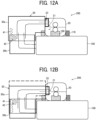
- FIGS. 12A and 12B are schematic views of a laminating system 200 according to an embodiment of the present disclosure.
- FIG. 12A is a schematic front view of a conveyor 30 before the adjustment of the vertical position.
- FIG. 12B is a schematic front view of the conveyor 30 after the adjustment of the vertical position.
- the conveyor 30 is divided into an upper conveyor part 30a and a lower conveyor part 30b, and is extendable in the vertical direction.
- the upper conveyor part 30a is provided with a vertical adjusting rack 41.
- the lower conveyor part 30b is provided with a pinion 42 meshed with the vertical adjusting rack 41 and a vertical adjusting knob coupled to the pinion 42.
- the vertical adjusting knob is located outside the conveyor 30 and can be operated by a user.
- the vertical adjusting knob When the vertical adjusting knob is turned, the upper conveyor part 30a is moved up and down with respect to the lower conveyor part 30b by the meshing of the vertical adjusting rack 41 and the pinion 42. Accordingly, for example, when the height of an inlet 21 serving as a film insertion port (or a sheet insertion port) of the lamination fixing device 20 is different from the height of an ejection port 33 of the conveyor 30 ( FIG. 12A ), the vertical adjusting knob can be turned to align the ejection port 33 of the conveyor 30 with the inlet 21 of the lamination fixing device 20 and adjust the height of the inlet 21 with the height of the ejection port 33 ( FIG. 12B ). In other words, the vertical misalignment between the lamination fixing device 20 and the conveyance guide plate can be corrected.
- Such height adjustment allows a plurality of types of lamination fixing devices 20, which are different in the height of the inlet 21, to be installed to the sheet separation device 100.
- the user can select, as the lamination fixing device 20, any other suitable lamination fixing device than the one provided as a default, and quality defects due to delivery failure of the sheet Sp to the inlet 21 can be reduced.
- FIGS. 13A and 13B are schematic views of a laminating system 200 according to an embodiment of the present disclosure.
- FIG. 13A illustrates the laminating system 200 with the ejection angle of an ejection port 33 oriented upward.
- FIG. 13B illustrates the laminating system 200 with the ejection angle of the ejection port 33 oriented downward.
- the angle of the ejection port 33 of the conveyor 30 can be adjusted to cope with various distances. Adjusting the angle of the ejection port 33 allows the sheet Sp sent from the sheet separation device 100 to be guided to the nip portion of the lamination fixing device 20 and reliably delivered to the lamination fixing device 20.
- multiple types of lamination fixing devices 20 can be installed, the user can select a lamination fixing device 20 from the multiple types of lamination fixing devices 20, and the sheet Sp is reliably delivered to the inlet 21 of the lamination fixing device 20, thus achieving the effect of enhancing the quality.
- FIG. 14 is a schematic perspective view of the conveyor 30 with an ejection-angle adjusting lever 43.
- the ejection-angle adjusting lever 43 is disposed on a side surface of the conveyor 30, and the user can move the ejection-angle adjusting lever 43 vertically to adjust the ejection angle of the ejection port 33 vertically.
- FIG. 15 illustrates a schematic plan view of a laminating system 200 according to an embodiment of the present disclosure.
- a conveyor 30 is not illustrated in FIG. 15 .
- a mark 45 indicating the direction of installation of the lamination fixing device is disposed on an upper surface of a sheet separation device 100. If the direction of installation of the lamination fixing device 20 is wrong, a conveyance failure occurs between the conveyor 30 and the lamination fixing device 20.
- the mark 45 allows the user to align the conveyance direction of the lamination fixing device 20 with (the direction of) the mark 45, thus preventing the user from misinstalling the lamination fixing device 20.
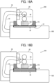
- FIGS. 16A and 16B are schematic views of a laminating system 200 according to an embodiment of the present disclosure.
- FIG. 16A illustrates the laminating system 200 with the vertical positions of a lamination fixing device 20 and a conveyor 30 shifted from each other.
- FIG. 16B illustrates the laminating system 200 with the vertical positions aligned with each other.
- the internal configuration of the sheet separation device 100 and sheet trays are omitted in FIGS. 16A and 16B .
- a height adjustment mechanism 50 serving as a vertical adjustment mechanism for the lamination fixing device 20 is disposed in the sheet separation device 100.
- the height adjustment mechanism 50 has a stage 51 movable in the vertical direction. First positioners 160, second positioners 170, the lamination fixing device 20, and other components are mounted on a stage 51.
- the stage 51 is operated to align the conveyance path 48 of the lamination fixing device 20 with the conveyance-path extension line 47 of the conveyor 30 ( FIG. 16B ), thus preventing the occurrence of quality defects.
- the alignment of the conveyance path 48 of the lamination fixing device 20 with the conveyance-path extension line 47 of the conveyor 30 can be performed through the success or failure of the attachment of the conveyor 30 to the laminating system 200 and the occurrence of quality defects.
- the stage 51 allows the laminating system 200 to be adapted to various lamination fixing devices 20.
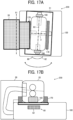
- FIGS. 17A and 17B are schematic views of a laminating system 200 according to an embodiment of the present disclosure.
- FIG. 17A is a schematic plan view of the laminating system 200 according to the present embodiment.
- FIG. 17B is a schematic front view of the laminating system 200 illustrated in FIG. 17A .
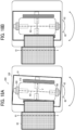
- FIGS. 18A and 18B are schematic plan views of the laminating system 200 before and after parallelism adjustment.
- FIG. 18A illustrates the laminating system 200 before the parallelism adjustment.
- FIG. 18B illustrates the laminating system 200 after the parallelism adjustment.
- the laminating system 200 has a parallelism adjustment mechanism 60 that adjusts the parallelism of the lamination fixing device 20 with respect to a conveyor 30. Accordingly, the parallelism of the lamination fixing device 20 with respect to an orthogonal line 61 to the conveyance center of the conveyor 30 can be adjusted, thus preventing the occurrence of, for example, wrinkles.
- the parallelism means the parallelism between the orthogonal line 61 with respect to the conveyance center of the conveyor 30 and an orthogonal line 63 with respect to a conveyance center V of the lamination fixing device 20.
- the stage 51, first positioners 160, and second positioners 170 are attached to and integrated with the sheet separation device 100.
- the parallelism adjustment mechanism 60 has the stage 51 and a parallelism adjustment knob 62. The user can rotate the parallelism adjustment knob 62 in the direction indicated by double arrow in FIG. 17A to move the stage 51, and can align the orthogonal line 63 with respect to the conveyance center V of the lamination fixing device 20 mounted on the stage 51 with the orthogonal line 61 with respect to the conveyance center of the conveyor 30.
- the positioning of a lamination fixing device 20 by positioners may be insufficient depending on the exterior shape.
- the parallelism adjustment mechanism 60 can adjust the stage 51 integrated with the first positioners 160 and the second positioners 170 in the lateral direction.
- the orthogonal line 63 with respect to the conveyance center V of the lamination fixing device 20 can be finely adjusted, and the occurrence of quality defects caused by conveyance failure can be prevented.
- Such adjustment can be performed through the success or failure of the attachment of the conveyor 30 to the laminating system 200 and the presence or absence of the occurrence of quality defects.
- a laminating system includes: a sheet separation device to separate a two-ply sheet to form the two-ply sheet having an inner sheet inserted therein.
- the sheet separation device has an upper surface on which a lamination fixing device is to be installed.
- the sheet separation device includes a plurality of first positioners to restrict a position of the lamination fixing device in a direction orthogonal to a conveyance direction of the two-ply sheet. Each of the first positioners is movable in the direction orthogonal to the conveyance direction of the two-ply sheet.
- the sheet separation device includes a second positioner to restrict a position of the lamination fixing device in the conveyance direction of the two-ply sheet.
- the second positioner is movable in the conveyance direction of the two-ply sheet.
- the laminating system further includes a conveyor to convey the two-ply sheet from the sheet separation device to the lamination fixing device.
- the conveyor is detachably attached to the lamination fixing device.
- the conveyor contacts the lamination fixing device to restrict movement of the lamination fixing device.
- the conveyor has a rotatable roller.
- the conveyor is extendable in a vertical direction.
- an angle of an ejection port of the conveyor is adjustable.
- the sheet separation device has a mark on an upper surface of the sheet separation device, and the mark indicates a direction of installation of the lamination fixing device.
- the sheet separation device includes a vertical adjustment mechanism to adjust the lamination fixing device in a vertical direction.
- the laminating system according to any one of the first to ninth aspects further includes a parallelism adjustment mechanism to adjust parallelism of the lamination fixing device with respect to the conveyor.
Landscapes
- Engineering & Computer Science (AREA)
- Mechanical Engineering (AREA)
- Sheets, Magazines, And Separation Thereof (AREA)
Abstract
Description
- Embodiments of the present disclosure relate to a sheet separation device and a laminating system.
- A lamination technology is known that inserts an inner sheet (e.g., sheet of paper or photo) between a two-ply lamination sheet or lamination film (e.g., a lamination pouch or lamination folder) and applies heat and pressure to the two-ply lamination sheet to bond the two-ply lamination sheet. The two-ply sheet is made of two sheets (plies) bonded (sealed) on one side as if one sheet is folded.
- In the laminating process, since a series of operations have been performed manually by a user, a great deal of time and labor are required when a large number of sheets are laminated.
- For this reason, a sheet separation device has been proposed in which two sheets of a two-ply sheet are separated off by winding the two-ply sheet around a rotating member and generating a difference in the circumferential length of the winding between a sheet on the inner circumferential side and a sheet on the outer circumferential side from a geometric relationship (see
Japanese Unexamined Patent Application Publication No. 2020-121868 - Further, for the purpose of automating the laminating process, a structure in which a laminating apparatus is connected in series to an apparatus that separates two sheets of film has also been proposed (see
Japanese Unexamined Patent Application Publication No. 2011-68115 - However, in the configuration of
Japanese Unexamined Patent Application Publication No. 2011-68115 - In addition, since the user removes laminated sheets one by one, the workability of the user may deteriorate when the laminating process is performed on a large number of sheets.
- In the case of a laminating process of inserting a printed matter into a laminated film and applying heat and pressure to adhere the laminated film and the printed matter, the printed matter such as a bulletin board or a menu table is sandwiched between sheets of the film, thus increasing the strength of the printed matter and protecting the printed matter from contamination. However, the laminating process requires a user to manually separate off the film, sandwich the printed matter to be sandwiched at an accurate position, and then perform the laminating process by a laminating machine, which is a time-consuming work.
- For this reason,
Japanese Unexamined Patent Application Publication No. 2020-121868 - In order to automatically perform laminating with a smaller installation space of the laminator, the laminator may be placed on the sheet separation device and couple to the sheet separation device. However, in such a configuration, a guide path for guiding the output material conveyed from the sheet separation device is needed. In order to convey the output of the sheet separation device to the laminator, the position of the laminator needs to be aligned with the conveyance path of the output material from the sheet separation device.
- However, since various laminators are commercially available, the center of the conveyance roller of the sheet separation device in the longitudinal direction may not be aligned with the center of the outer periphery of the laminator. Alternatively, the distance from the outer periphery of the laminator to the sheet insertion port differs for each laminator in the transverse direction, or the distance from the installation surface of the laminator to the sheet insertion port differs for each laminator in the vertical direction. Accordingly, the positioning of the laminator cannot be easily performed.
- Accordingly, an object of the present disclosure is to provide a sheet separation device that can be coupled to a lamination fixing device and that can collect ejected laminated sheets at once without increasing the lateral width (footprint) of the entire device.
- According to an embodiment of the present disclosure, there is provided a sheet separation device for separating two sheets of a two-ply sheet, in which the two sheets are overlapped and a part of the two sheets are joined, and inserting at least one sheet medium between the two sheets. The sheet separation device includes an upper surface, an ejection tray, and a conveyor. A lamination fixing device that laminates the two-ply sheet including the at least one sheet medium inserted between the two sheets is to be mounted on the upper surface. The ejection tray is disposed on the upper surface. The two-ply sheet laminated by the lamination fixing device and ejected from an ejection port of the lamination fixing device is to be stacked on the ejection tray. The conveyor is coupled to the lamination fixing device to convey the two-ply sheet including the at least one sheet medium inserted between the two sheets from the sheet separation device to the lamination fixing device.
- The sheet separation device according to an embodiment of the present disclosure can mount the lamination fixing device on the upper surface thereof. Thus, a series of laminating processes can be performed without increasing the lateral width (footprint) of the entire apparatus. The ejected laminated sheets can be collected at once by the sheet ejection tray disposed on the upper surface of the sheet separation device. Accordingly, the workability can be enhanced.
- In addition, in light of the above-described circumstances, an object of the present disclosure is to save the time and effort in laminating using a sheet separation device and a commercially-available lamination fixing device and simplify the positioning of the lamination fixing device in mounting the lamination fixing device onto the sheet separation device in order to reduce the installation space.
- In order to solve the problem, according to an embodiment of the present disclosure, a laminating system includes a sheet separation device. The sheet separation device separates a two-ply sheet to form the two-ply sheet having an inner sheet inserted in the two-ply sheet. The sheet separation device has an upper surface on which a lamination fixing device is to be installed. The sheet separation device includes a plurality of first positioners to restrict a position of the lamination fixing device in a direction orthogonal to a conveyance direction of the two-ply sheet. Each one of the first positioners is movable in the direction orthogonal to the conveyance direction of the two-ply sheet.
- In the laminating system according to an embodiment of the present disclosure, the time and effort in laminating using the sheet separation device and a commercially-available lamination fixing device can be saved, and the positioning of the lamination fixing device in mounting the lamination fixing device onto the sheet separation device can be simplified in order to reduce the installation space.
- A more complete appreciation of embodiments of the present disclosure and many of the attendant advantages and features thereof can be readily obtained and understood from the following detailed description with reference to the accompanying drawings, wherein:
-
FIG. 1 is a front view of a sheet separation device according to an embodiment of the present disclosure; -
FIG. 2 is a top plan view of the sheet separation device ofFIG. 1 ; -
FIG. 3A is a front view of a height adjustment mechanism before adjustment of the height of a lamination fixing device; -
FIG. 3B is a front view of the height adjustment mechanism ofFIG. 3A after the adjustment of the height of the lamination fixing device; -
FIG. 4A is a front view of a position adjustment mechanism before adjustment of the position of a sheet ejection tray; -
FIG. 4B is a front view of the position adjustment mechanism ofFIG. 4A after the adjustment of the position of the sheet ejection tray; -
FIG. 5A is a top plan view of an overall configuration of a laminating system according to an embodiment of the present disclosure; -
FIG. 5B is a front view of the overall configuration of the laminating system ofFIG. 5A ; -
FIGS. 6A and 6B are schematic views of the laminating system illustrated inFIGS. 5A and 5B ; -
FIGS. 7A and 7B are schematic plan views of the laminating system illustrated inFIGS. 5A and 5B ; -
FIG. 8 is a schematic view of a laminating system according to an embodiment of the present disclosure; -
FIG. 9 is a schematic view of a laminating system according to an embodiment of the present disclosure; -
FIG. 10 is a schematic perspective view of a conveyor as viewed in a direction indicated by arrow C inFIG. 8 ; -
FIGS. 11A and 11B are schematic views of a laminating system according to an embodiment of the present disclosure; -
FIGS. 12A and 12B are schematic views of a laminating system according to an embodiment of the present disclosure; -
FIGS. 13A and 13B are schematic views of a laminating system according to an embodiment of the present disclosure; -
FIG. 14 is a schematic perspective view of a conveyor with an ejection-angle adjusting lever; -
Figure 15 is a schematic plan view of a laminating system according to an embodiment of the present disclosure; -
FIGS. 16A and 16B are schematic views of a laminating system according to an embodiment of the present disclosure; -
FIGS. 17A and 17B are schematic views of a laminating system according to an embodiment of the present disclosure; and -
FIGS. 18A and 18B are schematic plan views of a laminating system before and after parallelism adjustment. - The accompanying drawings are intended to depict embodiments of the present disclosure and should not be interpreted to limit the scope thereof. The accompanying drawings are not to be considered as drawn to scale unless explicitly noted. Also, identical or similar reference numerals designate identical or similar components throughout the several views.
- In describing embodiments illustrated in the drawings, specific terminology is employed for the sake of clarity. However, the disclosure of this specification is not intended to be limited to the specific terminology so selected and it is to be understood that each specific element includes all technical equivalents that have a similar function, operate in a similar manner, and achieve a similar result.
- Referring now to the drawings, embodiments of the present disclosure are described below. As used herein, the singular forms "a," "an," and "the" are intended to include the plural forms as well, unless the context clearly indicates otherwise.
- A description is given below of an embodiment of the present disclosure.
-
FIG. 1 is a front view of asheet separation device 100 according to an embodiment of the present disclosure.FIG. 2 is a top plan view of thesheet separation device 100 ofFIG. 1 . Thesheet separation device 100 according to the present embodiment separates two sheets (plies) of a two-ply sheet, which is referred to as a lamination sheet S in the following description, to insert and sandwich an inner sheet P between the separated sheets of the lamination sheet S. - The lamination sheet S is a two-ply sheet in which two sheets are overlapped and bonded together at a portion (or a side) of the two-ply sheet. For example, there is a two-ply sheet in which a first side as a transparent sheet such as a transparent polyester sheet and a second side facing the first side as a transparent or opaque sheet are bonded at one side of the two-ply sheet. Examples of the two-ply sheet also include a lamination film.
- The inner sheet P is an example of the sheet medium (sheet-shaped medium) that is inserted into the two-ply sheet. Examples of the sheet medium include thick paper, postcards, envelopes, plain paper, thin paper, coated paper, art paper, tracing paper, and overhead projector (OHP) transparencies.
- The
sheet separation device 100 according to the present embodiment is provided with alamination fixing device 20 and asheet ejection tray 40 on anupper surface 100a of thesheet separation device 100. Thelamination fixing device 20 laminates a lamination sheet S with an inner sheet P inserted and sandwiched between the two sheets of the lamination sheet S, which is referred to as a sheet Sp in the following description. The sheet Sp that has been laminated by thelamination fixing device 20 is stacked on thesheet ejection tray 40. Thesheet separation device 100 further includes aconveyor 30 to be coupled to thelamination fixing device 20 and convey the sheet Sp from thesheet separation device 100 to thelamination fixing device 20. - The
lamination fixing device 20 can be detachably mounted on theupper surface 100a of thesheet separation device 100. Thelamination fixing device 20 may have a separate housing (as a laminator or a laminating device), which is provided separately from a housing of thesheet separation device 100. Thesheet ejection tray 40 is disposed downstream from thelamination fixing device 20 in a sheet ejection direction in which the sheet Sp is ejected, and stacks the sheets Sp ejected from anejection port 23 of thelamination fixing device 20. - The
conveyor 30 is disposed downstream from thesheet separation device 100 in a sheet conveyance direction A, which is indicated by arrow A inFIG. 1 , and has aconveyance passage 32 through which the sheet Sp is, while being reversed by 180°, conveyed to thelamination fixing device 20. A sheet conveyance direction C in thelamination fixing device 20, which is indicated by arrow C inFIG. 1 , is a direction opposite to the sheet conveyance direction A in thesheet separation device 100. - A description is given below of a series of operations of feeding the lamination sheet S, separating two sheets of the lamination sheet S, inserting the inner sheet P into the lamination sheet S, and laminating the lamination sheet S enclosing the inner sheet P by application of heat and pressure, performed by the
sheet separation device 100 according to the present embodiment. - The present applicant has already filed a patent application for a technique of separating a lamination sheet S (by winding a two-ply sheet (lamination sheet S) around a rotating member into two sheets and generating a difference in the circumferential length between a sheet on the inner circumferential side and a sheet on the outer circumferential side from a geometrical relationship to separate two sheets of the two-ply sheet, as
Japanese Unexamined Patent Application Publication No. 2020-121868 sheet separation device 100 according to an embodiment of the present disclosure. - The
sheet separation device 100 includes asheet tray 102, apickup roller 105, and anentrance roller pair 108. Thesheet tray 102 stacks lamination sheets S thereon. Thepickup roller 105 feeds a lamination sheet S from thesheet tray 102. Thesheet separation device 100 further includes asheet tray 103 and apickup roller 106. Thesheet tray 103 stacks inner sheets P thereon. Thepickup roller 106 feeds an inner sheet P from thesheet tray 103. - The
sheet separation device 100 further includes theentrance roller pair 108, a roller pair including a windingroller 109 and a drivenroller 110, and anexit roller pair 113. Theentrance roller pair 108 is disposed downstream from thepickup roller 105 and thepickup roller 106 in the sheet conveyance direction. The windingroller 109 serves as a rotary member. - As illustrated in
FIG. 1 , thesheet separation device 100 according to the present embodiment loads the lamination sheet S and the inner sheet P on separate trays. In the present embodiment, the lamination sheet S is stacked on thesheet tray 102 such that a part of the lamination sheet S in which two sheets are bonded is positioned on the downstream side in the sheet feed direction (sheet conveyance direction) in which the lamination sheet S is fed by thepickup roller 105. - In the
sheet separation device 100, thepickup roller 105 picks up a lamination sheet S, the roller pair including the windingroller 109 and the drivenroller 110 conveys the lamination sheet S in the sheet conveyance direction A, which is indicated by arrow A inFIG. 1 , to send the lamination sheet S to theexit roller pair 113. - Then, the
exit roller pair 113 and the windingroller 109 rotate in reverse to convey the lamination sheet S in a direction indicated by arrow B inFIG. 1 . The lamination sheet S conveyed in the direction indicated by arrow B inFIG. 1 is wound around the windingroller 109. As the lamination sheet S is wound around the windingroller 109 for more than one round, the leading end of the lamination sheet S in the sheet conveyance direction (i.e., the side where the two sheets of the lamination sheet S are overlapped but not bonded) is fixed to the windingroller 109. - When the lamination sheet S is further wound around the winding
roller 109, a difference is created in the circumferential length between the two sheets of the lamination sheet S, to be more specific, the sheet on the inner circumference side and the sheet on the outer circumference side of the lamination sheet S. In other words, a difference in the amount of winding of the lamination sheet S around the circumference of the windingroller 109 is created between the two sheets. Due to the difference, the two sheets of the lamination sheet S start separating from each other between theexit roller pair 113 and the windingroller 109. - Then, the slack of the sheet on the inner circumference side is collected between the
exit roller pair 113 and the windingroller 109, which can create a gap (space) between the sheet on the inner circumference side and the sheet on the outer circumference side. - Then, the
sheet separation device 100 causes separation plates to be inserted into the gap created in the lamination sheet S from both lateral sides of the lamination sheet S. As the lamination sheet S is continuously conveyed, the lamination sheet S widely opens. - The
sheet separation device 100 then rotates theentrance roller pair 108 to convey an inner sheet P conveyed from thesheet tray 102 toward theexit roller pair 113 in the sheet conveyance direction A. The inner sheet P is conveyed between the two sheets of the lamination sheet S such that the inner sheet P contacts the bonded portion of the lamination sheet S. Thesheet separation device 100 then rotates theexit roller pair 113 in the clockwise direction to cause the lamination sheet S and the inner sheet P to meet to enclose the inner sheet P in the lamination sheet S that is open. - The lamination sheet S enclosing the inner sheet P (i.e., the sheet Sp) is conveyed through an
exit port 115 of thesheet separation device 100 to thelamination fixing device 20 via theconveyance passage 32 in theconveyor 30. - For a detailed description of a series of operations of the sheet separation device 100 (operations from the separation of the lamination sheet S to the insertion of the inner sheet P), see
Japanese Unexamined Patent Application Publication No. 2020-121868 - The
lamination fixing device 20 includes aninlet 21 and a thermalpressure roller pair 22. Theinlet 21 is an inlet port of a sheet to be laminated, in other words, a sheet to be thermally fixed. The thermalpressure roller pair 22 includes a heater. The thermalpressure roller pair 22 heats and presses (laminates) the sheet Sp. - In the case where the two-ply sheet is a lamination film, when the adhesive (made of, e.g., ethylene vinyl acetate (EVA)) applied to the inner side of the lamination film reaches the melting point, the adhesive melts and the two sheets of the two-ply sheet are bonded to each other. The sheet Sp laminated in this manner is ejected from the
lamination fixing device 20 through an ejection roller. - The
lamination fixing device 20 is a separate unit having a housing different from a housing of thesheet separation device 100. Thelamination fixing device 20 may be a commercially-available lamination device (a lamination device already available on the market). Further, various lamination devices are on the market from various manufacturers and have different sizes, different lamination (fixing) processing speeds, or both. Such lamination devices typically employ a processing speed of, for example, one to three sheets per minute. - The laminated sheet Sp ejected from the
lamination fixing device 20 is stacked on thesheet ejection tray 40. Thesheet ejection tray 40 can continuously stack a large number of laminated sheets Sp. Thus, unlike typical laminating devices, the user does not need to remove the ejected sheets one by one, and the workability can be enhanced. - As described above, the
sheet separation device 100 according to the present embodiment can automatically perform a series of operations including feeding of the lamination sheet S, separation of the lamination sheet S, insertion of the inner sheet P, bonding by heat and pressure, and stacking of the laminated sheets without manual intervention, thus enhancing the workability of the user. - In addition, the
sheet separation device 100 according to the present embodiment is advantageous in that the lateral width (footprint) of the entire device is not increased since thelamination fixing device 20 can be mounted on the upper surface of thesheet separation device 100. - An advantageous structure of an embodiment of the present disclosure will be described below.
-
FIGS. 3A and 3B illustrate a height adjustment mechanism that adjusts the height of a lamination fixing device, according to an embodiment of the present disclosure.FIG. 3A is a front view of the height adjustment mechanism before adjustment of the height of the lamination fixing device.FIG. 3B is a front view of the height adjustment mechanism after the adjustment of the height of the lamination fixing device. InFIGS. 3A and 3B , the same reference numerals as those inFIG. 1 denote the same components, and detailed description thereof may be omitted below. - Although an already-available lamination fixing device (laminator) can be mounted on a
sheet separation device 100, the height of thesheet separation device 100 may not match and a lamination sheet S from thesheet separation device 100 may not be received depending on the model of the already-available lamination fixing device. - For example, if the height of the outlet of a
conveyance passage 32 of theconveyor 30 is different from the height of aninlet 21 of alamination fixing device 20a, a sheet Sp from theconveyor 30 is not conveyed into thelamination fixing device 20a (seeFIG. 3A ). - In such a case, the height of the
lamination fixing device 20a (the inlet 21) with respect to anupper surface 100a of thesheet separation device 100 is adjusted by aheight adjustment mechanism 50 disposed on theupper surface 100a of the sheet separation device 100 (seeFIG. 3B ). - The
height adjustment mechanism 50 is, for example, a mechanism by which adevice holder 54 can be moved in the vertical direction along aheight adjustment rail 52. Thelamination fixing device 20a is held on thedevice holder 54 and the height is adjusted between theinlet 21 of thelamination fixing device 20a and the outlet of theconveyance passage 32 of theconveyor 30. Thus, the sheet Sp can be stably conveyed. - As an example of the
height adjustment mechanism 50, a rack and pinion may be used. For example, theheight adjustment rail 52 may be formed of a rack, and thedevice holder 54 may be provided with a pinion gear. The pinion gear is rotated, either manually or by a motor drive, to move thedevice holder 54 along theheight adjustment rail 52. -
FIGS. 4A and 4B illustrate a position adjustment mechanism that adjusts the position of a sheet ejection tray, according to an embodiment of the present disclosure.FIG. 4A is a front view of the position adjustment mechanism before adjustment of the position of the sheet ejection tray.FIG. 4B is a front view of the position adjustment mechanism after the adjustment of the position of the sheet ejection tray. InFIGS. 4A and 4B , the same reference numerals as those inFIG. 1 denote the same components, and detailed description thereof may be omitted below. - As illustrated in
FIG. 4A , when alamination fixing device 20b mounted on asheet separation device 100 is long in the horizontal direction, an inserted lamination sheet having been laminated may not be appropriately stacked on asheet ejection tray 40. This may occur even when a lamination fixing device is short in the horizontal direction. - In such a case, as illustrated in
FIG. 4B , aposition adjustment mechanism 56 disposed on anupper surface 100a of thesheet separation device 100 moves thesheet ejection tray 40 in a sheet ejection direction (or a direction opposite to the sheet ejection direction), and adjusts the position of thelamination fixing device 20b with respect to theejection port 23. - The
position adjustment mechanism 56 is a mechanism that has a supporting member such as a rail, supports thesheet ejection tray 40, and can move thesheet ejection tray 40 in the horizontal direction. - Thus, the laminated sheet Sp can be stably ejected to the
sheet ejection tray 40. Further, since the laminated sheets Sp can be stacked without receiving unnecessary external force, the occurrence of curling in the stacked sheets can be reduced and the quality can be stabilized. - Some embodiments of the present disclosure have been described in detail above. The above-described embodiments are examples and can be modified within the scope not departing from the gist of the present disclosure. For example, the above-described configurations (e.g., Part 1 and Part 2) may be combined with each other.
- Before describing further embodiments of the present disclosure, preliminary matters for facilitating understanding of the further embodiments will be described below.
- For example, a laminating apparatus in the related art has a relatively large lateral width (footprint) because a heat pressure member (e.g., a fixing device) is horizontally disposed downstream from a sheet separation device in a sheet conveyance direction (see FIG. 26 of
Japanese Unexamined Patent Application Publication No. 2020-121868 - Then, to reduce the occupied area of a laminating apparatus and make effective use of an already-available laminator, the inventors have conceived of a configuration in which an already-available laminator (e.g., a lamination fixing device) is placed on a sheet separation device and a two-ply sheet is conveyed between the laminator and the sheet separation device through a sheet conveyance passage.
- In this configuration, an already-available laminator is employed to automatically perform a series of laminating processes at low cost.
- Such already-available laminators are manufactured and sold as lamination apparatuses by various manufacturers. Such lamination apparatuses have various sizes and lamination processing capabilities (such as the conveyance speeds). For this reason, if the conveyances speed is different between a sheet separation device and a laminator coupled to each other, wrinkles or skew (inclined conveyance) are generated in a lamination sheet. Accordingly, it is unlikely that the thermal fixing is appropriately performed.
- In this case, another laminator may be employed or the sheet conveyance passage may be adjusted (redesigned) in accordance with the specification of the laminator, which impairs the convenience.
- In the following embodiments, a description is given of a laminating system that can absorb the difference in the conveyance speed between a sheet separation device and a lamination fixing device to prevent the occurrence of wrinkles or skew of a two-ply sheet enclosing a sheet medium.
- A first embodiment is described below.
- A description is given of an overall configuration of a laminating system according to an embodiment of the present disclosure, with reference to
FIGS. 5A and 5B. FIG. 5A is a top plan view of a laminating system according to an embodiment of the present disclosure.FIG. 5B is a front view of the laminating system ofFIG. 5A . Thelaminating system 200 performs a series of operations of feeding a lamination sheet S (i.e., a two-ply sheet), separating two sheets of the lamination sheet S, inserting an inner sheet P into the lamination sheet S, and laminating the lamination sheet S enclosing the inner sheet P, by application of heat and pressure, on a stand-alone basis. This series of operations is carried out automatically without any aid of a user. For this reason, thelaminating system 200 can enhance and provide the convenience better than a laminating system in the related art. - The lamination sheet S is a two-ply sheet in which two sheets are overlapped and bonded together at a portion (or a side) of the two-ply sheet. For example, there is a two-ply sheet in which a first side as a transparent sheet such as a transparent polyester sheet and a second side facing the first side as a transparent or opaque sheet are bonded at one side of the two-ply sheet. Examples of the two-ply sheet also include a lamination film.
- The inner sheet P is an example of the sheet medium (sheet-shaped medium) that is inserted into the two-ply sheet. Examples of the sheet medium include thick paper, postcards, envelopes, plain paper, thin paper, coated paper, art paper, tracing paper, and overhead projector (OHP) transparencies.
- As illustrated in
FIGS. 5A and 5B , thelaminating system 200 includes asheet separation device 100 that separates off two sheets of the lamination sheet S and sandwiches the inner sheet P between the two sheets of the lamination sheet S and has an upper surface on which alamination fixing device 20 is to be mounted. Thelamination fixing device 20 is a commercially-available device selected by the user according to the user's preference and having a housing provided separately from a housing of thesheet separation device 100, and is mounted on the upper surface of thesheet separation device 100. Thelamination fixing device 20 can heat and press the lamination sheet S enclosing the inner sheet P, which may also be referred to as an inserted lamination sheet Sp. Thelaminating system 200 further includes aconveyor 30 that conveys the sheet Sp from theexit port 115 of thesheet separation device 100 to theinlet 21 of thelamination fixing device 20. - As described above, in the
laminating system 200 according to the present embodiment, thelamination fixing device 20 is disposed above thesheet separation device 100. Theconveyor 30 is disposed downstream from thesheet separation device 100 in a sheet conveyance direction A, which is indicated by arrow A inFIG. 5B , and has aconveyance passage 32 through which the sheet Sp is inverted by 180 degrees and is conveyed to thelamination fixing device 20. A sheet conveyance direction C in thelamination fixing device 20, which is indicated by arrow C inFIG. 5B , is a direction opposite to the sheet conveyance direction A in thesheet separation device 100. - A description is given of a series of operations of feeding the lamination sheet S, separating two sheets of the lamination sheet S, inserting the inner sheet P into the lamination sheet S, and laminating the lamination sheet S enclosing the inner sheet P by application of heat and pressure, performed by the
laminating system 200 according to the present embodiment. - The present applicant has already filed a patent application for a technique of separating a lamination sheet S (by winding a two-ply sheet (lamination sheet S) around a rotating member into two sheets and generating a difference in the circumferential length between a sheet on the inner circumferential side and a sheet on the outer circumferential side from a geometrical relationship to separate two sheets of the two-ply sheet, as
Japanese Unexamined Patent Application Publication No. 2020-121868 sheet separation device 100 according to an embodiment of the present disclosure. - The
sheet separation device 100 includes asheet tray 102, apickup roller 105, and anentrance roller pair 108. Thesheet tray 102 stacks lamination sheets S thereon. Thepickup roller 105 feeds a lamination sheet S from thesheet tray 102. Thesheet separation device 100 further includes asheet tray 103 and apickup roller 106. Thesheet tray 103 stacks inner sheets P thereon. Thepickup roller 106 feeds an inner sheet P from thesheet tray 103. - The
sheet separation device 100 further includes anentrance roller pair 108, a roller pair including a windingroller 109 and a drivenroller 110, and anexit roller pair 113. Theentrance roller pair 108 is disposed downstream from thepickup roller 105 and thepickup roller 106 in the sheet conveyance direction. The windingroller 109 serves as a rotary member. - As illustrated in
FIG. 5B , thesheet separation device 100 according to the present embodiment loads the lamination sheet S and the inner sheet P on separate trays. In the present embodiment, the lamination sheet S is stacked on thesheet tray 102 such that a part of the lamination sheet S in which two sheets are bonded is positioned on the downstream side in the sheet feed direction (sheet conveyance direction) in which the lamination sheet S is fed by thepickup roller 105. - In the
sheet separation device 100, thepickup roller 105 picks up a lamination sheet S, the roller pair including the windingroller 109 and the drivenroller 110 conveys the lamination sheet S in the sheet conveyance direction A, which is indicated by arrow A inFIG. 5B , to send the lamination sheet S to theexit roller pair 113. - Then, the
exit roller pair 113 and the windingroller 109 rotate in reverse to convey the lamination sheet S in a direction indicated by arrow B inFIG. 5B . The lamination sheet S conveyed in the direction indicated by arrow B inFIG. 5B is wound around the windingroller 109. As the lamination sheet S is wound around the windingroller 109 for more than one round, the leading end of the lamination sheet S in the sheet conveyance direction (i.e., the side where the two sheets of the lamination sheet S are overlapped but not bonded) is fixed to the windingroller 109. - When the lamination sheet S is further wound around the winding
roller 109, a difference is created in the circumferential length between the two sheets of the lamination sheet S, to be more specific, the sheet on the inner circumference side and the sheet on the outer circumference side of the lamination sheet S. In other words, a difference in the amount of winding of the lamination sheet S around the circumference of the windingroller 109 is created between the two sheets. Due to the difference, the two sheets of the lamination sheet S start separating from each other between theexit roller pair 113 and the windingroller 109. - Then, the slack of the sheet on the inner circumference side is collected between the
exit roller pair 113 and the windingroller 109, which can create a gap (space) between the sheet on the inner circumference side and the sheet on the outer circumference side. - Then, the
sheet separation device 100 causes separation plates to be inserted into the gap created in the lamination sheet S from both lateral sides of the lamination sheet S. As the lamination sheet S is continuously conveyed, the lamination sheet S widely opens. For a detailed description of the winding process, seeJapanese Unexamined Patent Application Publication No. 2020-121868 - The
sheet separation device 100 then rotates theentrance roller pair 108 to convey an inner sheet P conveyed from thesheet tray 102 toward theexit roller pair 113 in the sheet conveyance direction A. The inner sheet P is conveyed between the two sheets of the lamination sheet S such that the inner sheet P contacts the bonded portion of the lamination sheet S. Thesheet separation device 100 then rotates theexit roller pair 113 in the clockwise direction to cause the lamination sheet S and the inner sheet P to meet to enclose the inner sheet P in the lamination sheet S that is open. - The lamination sheet S enclosing the inner sheet P (i.e., the sheet Sp) is conveyed through an
exit port 115 of thesheet separation device 100 to thelamination fixing device 20 via theconveyance passage 32 in theconveyor 30. - The
laminating system 200 illustrated inFIGS. 5A and 5B includes thesheet separation device 100 that separates a two-ply sheet to form a sheet Sp, which is a lamination sheet S having an inner sheet P inserted therein, and thelamination fixing device 20 disposed on the upper surface of thesheet separation device 100. Thesheet separation device 100 has, on the upper surface thereof, afirst positioner 160 that restricts the position of thelamination fixing device 20 in the direction orthogonal to the sheet conveyance direction, which may be referred to as the position of thelamination fixing device 20 in the orthogonal direction as appropriate, and asecond positioner 170 that restricts the position of thelamination fixing device 20 in the sheet conveyance direction, which may be referred to as the position of thelamination fixing device 20 in the conveyance direction as appropriate. Thesheet separation device 100 includes a plurality offirst positioners 160, each of which is movable in the direction orthogonal to the conveyance direction of the sheet Sp. Each of thefirst positioners 160 may be movable in a direction obliquely intersecting the conveyance direction of the sheet Sp. Thesheet separation device 100 includes a plurality ofsecond positioners 170, each of which is movable in the conveyance direction of the sheet Sp. Each of thesecond positioners 170 may be movable in a direction obliquely intersecting the conveyance direction of the sheet Sp. - If the position of the
lamination fixing device 20 in the conveyance direction is not fixed, the sheet Sp conveyed from thesheet separation device 100 may not be stably delivered to thelamination fixing device 20. For this reason, thefirst positioners 160 that restrict the position of thelamination fixing device 20 in the orthogonal direction are disposed on the upper surface of thesheet separation device 100 such that thefirst positioners 160 are movable in the direction orthogonal to the conveyance direction of the sheet Sp. Such a configuration allows the user to position thelamination fixing device 20 with respect to thesheet separation device 100, and the sheet Sp from thesheet separation device 100 can be stably delivered to thelamination fixing device 20 through theconveyor 30 positioned in thesheet separation device 100. Thus, the time and effort for performing a laminating process using a sheet separation device and a commercially-available lamination device can be saved, and the positioning of the lamination device on the sheet separation device can be simplified in order to reduce the installation space. - The
second positioners 170 that restrict the position of thelamination fixing device 20 in the sheet conveyance direction are disposed such that the second positioners are movable in the conveyance direction of the sheet Sp. As the position of thelamination fixing device 20 is restricted in the direction different from thefirst positioners 160 by thesecond positioners 170, thelamination fixing device 20 can be stably mounted on the upper surface of thesheet separation device 100. Further, even when the distance (corresponding to the distance X illustrated inFIG. 5B ) from the outer periphery of thelamination fixing device 20 to theinlet 21 serving as a film insertion port (sheet insertion port) is not constant among commercially-available lamination devices, the position of theconveyor 30 can be adjusted to be properly installed. Thus, the process from the separation of the film to the completion of the laminating can be automated. -
FIG. 5A illustrates a conveyance center V of thelamination fixing device 20 and a conveyance center W of thesheet separation device 100 in a direction orthogonal to the conveyance direction of thelamination fixing device 20. - In
FIG. 5B , the position of thelamination fixing device 20 in the conveyance direction of thelamination fixing device 20 is aligned with theconveyor 30 by thesecond positioner 170. - In the
laminating system 200 illustrated inFIGS. 5A and 5B , thelamination fixing device 20 is mounted on thesheet separation device 100. Thelamination fixing device 20 includes aninlet 21 and a thermalpressure roller pair 22. Theinlet 21 is an inlet port of a sheet to be laminated, in other words, a sheet to be thermally fixed. The thermalpressure roller pair 22 includes a heater. Thelamination fixing device 20 is a separate unit having a housing different from a housing of thesheet separation device 100. Thelamination fixing device 20 may be a commercially-available lamination device (a lamination device already available on the market). - Various lamination devices are on the market from various manufacturers and have different sizes, different lamination (fixing) processing speeds, or both. Such lamination devices typically employ a processing speed of, for example, one to three sheets per minute.
-
FIGS. 6A and 6B are schematic views of thelaminating system 200. Theconveyor 30, the internal configuration of thesheet separation device 100, and thesheet trays FIGS. 5A and 5B are omitted inFIGS. 6A and 6B. FIG. 6A is a plan view of thelaminating system 200.FIG. 6B is a front view of thelaminating system 200. -
First rails 181 extending in a direction orthogonal to the sheet conveyance direction andsecond rails 182 extending in the sheet conveyance direction are disposed on the upper portion of thesheet separation device 100. Thefirst positioners 160 and thesecond positioners 170 are disposed on thefirst rails 181 and thesecond rails 182, respectively. Thefirst positioner 160 is movable along thefirst rail 181 and the position of thefirst positioner 160 can be fixed on thefirst rail 181. Thesecond positioner 170 is movable along thesecond rail 182 and the position of thesecond positioner 170 can be fixed on thesecond rail 182. - A method of aligning the
lamination fixing device 20 using the above-described members is described below. - The user places the
lamination fixing device 20 on the top surface of thesheet separation device 100, moves thefirst positioners 160 along thefirst rails 181 to bring thefirst positioners 160 into contact with the outer periphery of thelamination fixing device 20, and fixes thefirst positioners 160 at th positions at which thefirst positioners 160 contact the outer periphery of thelamination fixing device 20. Thus, the position of thelamination fixing device 20 in the orthogonal position can be fixed. Then, the user moves thesecond positioners 170 along thesecond rails 182, brings the second positioners 172 into contact with the outer periphery of thelamination fixing device 20, and fixes the second positioners 172 at the positions at which the second positioners 172 contact the outer periphery of thelamination fixing device 20. Thus, the position of thelamination fixing device 20 in the conveyance direction can also be fixed, and thelamination fixing device 20 can be positioned with respect to thesheet separation device 100. - When a sheet is conveyed in the state where the
conveyor 30 is attached with thelamination fixing device 20 positioned with respect to thesheet separation device 100, the positions at which thefirst positioners 160 and thesecond positioners 170 are fixed can be adjusted such that a conveyance failure does not occur. -
FIGS. 7A and 7B are schematic plan views of thelaminating system 200. Theconveyor 30, the internal configuration of thesheet separation device 100, and thesheet trays FIGS. 5A and 5B are omitted inFIGS. 6A and 6B .FIG. 7A illustrates thelaminating system 200 before alignment of the conveyance center V of thelamination fixing device 20 and the conveyance center W of thesheet separation device 100 using thefirst positioners 160 and thesecond positioners 170.FIG. 7B illustrates thelaminating system 200 after the alignment of the conveyance center V and the conveyance center W. - As illustrated in
FIGS. 6A and 6B , since thefirst positioners 160 are movable along thefirst rails 181, thelamination fixing device 20 can be fixed to thesheet separation device 100 at any position in the orthogonal direction. As illustrated inFIG. 7A , an example of a failure that possibly occurs when the conveyance center V of thelamination fixing device 20 and the conveyance center W of thesheet separation device 100 are shifted from each other is a quality defect in which the sheet Sp fed from thesheet separation device 100 is fed to the outside of the width of the fixing roller of thelamination fixing device 20 and an end of the sheet Sp is completely laminated. However, as illustrated inFIG. 7B , according to the present embodiment, the conveyance center V of thelamination fixing device 20 and the conveyance center W of thesheet separation device 100 can be adjusted, so that the occurrence of such a quality defect can be prevented. In this way, the fixing positions of thefirst positioners 160 can be adjusted while checking whether a quality defect has occurred. -
FIGS. 8, 9 , and10 are schematic views of the configuration of theconveyor 30 that is attachable to and detachable from thelamination fixing device 20 and guides a sheet Sp from theexit port 115 of thesheet separation device 100 to theinlet 21 of thelamination fixing device 20. - In the embodiment illustrated in
FIG. 8 , theconveyor 30 has arotation fulcrum 34 that is rotatable relative to thelamination fixing device 20. The rotation fulcrum 34 disposed between thesheet separation device 100 and theconveyor 30 allows theconveyor 30 to rotate in the direction indicated by arrow Y inFIG. 8 around therotation fulcrum 34. Thus, theconveyor 30 can be attached to and detached from thelamination fixing device 20. The attachable and detachable configuration allows theconveyor 30 to be used in accordance with a variety oflamination fixing devices 20. Further, for a user who needs only thesheet separation device 100, the number of components can be reduced, thus reducing the size and cost of the device. - In the embodiment illustrated in
FIG. 9 , theconveyor 30 has on a mountingsurface 35 to attach to thesheet separation device 100 andpositioning bosses 36 on the mountingsurface 35. Thesheet separation device 100 has insertion holes 37 corresponding to thepositioning bosses 36. Thepositioning bosses 36 of theconveyor 30 can be inserted into and removed from the insertion holes 37 of thesheet separation device 100. Accordingly, theconveyor 30 can be attached to and detached from thesheet separation device 100 in the horizontal direction indicated by arrow Z inFIG. 9 , and thus can be attached to and detached from thelamination fixing device 20. -
FIG. 10 is a schematic perspective view of theconveyor 30 as viewed in the direction indicated by arrow C inFIG. 8 . In the embodiment illustrated inFIG. 10 , theconveyor 30 has anaccommodating region 38 to accommodate asecond positioner 170, thus avoiding the interference between thesecond positioner 170 and theconveyor 30 when theconveyor 30 is mounted. This configuration is illustrated inFIGS. 11A and 11B . As illustrated inFIG. 10 , theaccommodating region 38 is formed as a recess. As illustrated inFIGS. 11A and 11B , theaccommodating region 38 can accommodate thesecond positioner 170 when theconveyor 30 is mounted. Aninsertion port 31 for the sheet Sp is disposed in a lower portion of theconveyor 30, and anejection port 33 for the sheet Sp is disposed in an upper portion of theconveyor 30. - Since the
conveyor 30 is attachable to and detachable from thelamination fixing device 20, thelamination fixing device 20 can be easily installed to thesheet separation device 100 and can be easily replaced. The sheet Sp can be easily removed even when the sheet Sp is jammed. Further, for a user who needs only thesheet separation device 100, the number of components can be reduced, thus reducing the size and cost of the device. - In any of the embodiments illustrated in
FIGS. 5A and 5B ,8, and 9 , theconveyor 30 is brought into contact with thelamination fixing device 20 when theconveyor 30 is mounted. Thus, the movement of thelamination fixing device 20 is restricted. Since theconveyor 30 has the function of positioning thelamination fixing device 20, the number of components is reduced, and thus the size and cost of the device can be reduced. -
FIGS. 11A and 11B are schematic views of alaminating system 200 according to an embodiment of the present disclosure.FIG. 11A is a schematic plan view of thelaminating system 200 according to the present embodiment.FIG. 11B is a schematic front view of thelaminating system 200 illustrated inFIG. 11A . - In the present embodiment, a
pre-lamination roller 39 that corrects the inclination of a sheet Sp is disposed in a downstream portion of aconveyance passage 32 of aconveyor 30 in a conveyance direction of the sheet Sp. The conveying forces of conveyance rollers, such as anentrance roller pair 108 and anexit roller pair 113, in thesheet separation device 100 are deviated in the longitudinal direction of the conveyance rollers due to variations such as differences in the outer diameter among the conveyance rollers. Such deviation of the conveying force may cause a difference in conveying speed of a sheet Sp in the longitudinal direction, and the output material may be conveyed with an inclination with respect to the longitudinal direction of the conveyance rollers. If the inclination of the sheet Sp is large when the sheet Sp is fed from thesheet separation device 100 to thelamination fixing device 20, the sheet Sp may be clogged, resulting in a quality defect. - For this reason, the
pre-lamination roller 39 that corrects the inclination of the sheet Sp is disposed in theconveyance passage 32. Thepre-lamination roller 39 is rotatable by the power supplied from a driving source disposed in the device. When the sheet Sp impinges thepre-lamination roller 39, the leading end of the sheet Sp is aligned with thelamination fixing device 20 before entering thelamination fixing device 20, that is, the skew of the sheet Sp is corrected. Accordingly, the occurrence of quality defects caused by conveyance failure can be prevented. -
FIGS. 12A and 12B are schematic views of alaminating system 200 according to an embodiment of the present disclosure.FIG. 12A is a schematic front view of aconveyor 30 before the adjustment of the vertical position.FIG. 12B is a schematic front view of theconveyor 30 after the adjustment of the vertical position. - In the present embodiment, the
conveyor 30 is divided into anupper conveyor part 30a and alower conveyor part 30b, and is extendable in the vertical direction. Theupper conveyor part 30a is provided with avertical adjusting rack 41. Thelower conveyor part 30b is provided with apinion 42 meshed with thevertical adjusting rack 41 and a vertical adjusting knob coupled to thepinion 42. The vertical adjusting knob is located outside theconveyor 30 and can be operated by a user. - When the vertical adjusting knob is turned, the
upper conveyor part 30a is moved up and down with respect to thelower conveyor part 30b by the meshing of thevertical adjusting rack 41 and thepinion 42. Accordingly, for example, when the height of aninlet 21 serving as a film insertion port (or a sheet insertion port) of thelamination fixing device 20 is different from the height of anejection port 33 of the conveyor 30 (FIG. 12A ), the vertical adjusting knob can be turned to align theejection port 33 of theconveyor 30 with theinlet 21 of thelamination fixing device 20 and adjust the height of theinlet 21 with the height of the ejection port 33 (FIG. 12B ). In other words, the vertical misalignment between thelamination fixing device 20 and the conveyance guide plate can be corrected. Such height adjustment allows a plurality of types oflamination fixing devices 20, which are different in the height of theinlet 21, to be installed to thesheet separation device 100. Thus, the user can select, as thelamination fixing device 20, any other suitable lamination fixing device than the one provided as a default, and quality defects due to delivery failure of the sheet Sp to theinlet 21 can be reduced. -
FIGS. 13A and 13B are schematic views of alaminating system 200 according to an embodiment of the present disclosure.FIG. 13A illustrates thelaminating system 200 with the ejection angle of anejection port 33 oriented upward.FIG. 13B illustrates thelaminating system 200 with the ejection angle of theejection port 33 oriented downward. - Commercially-available
lamination fixing devices 20 have various distances from the installation surface thereof to a nip portion between a thermalpressure roller pair 22. For this reason, in the present embodiment, the angle of theejection port 33 of theconveyor 30 can be adjusted to cope with various distances. Adjusting the angle of theejection port 33 allows the sheet Sp sent from thesheet separation device 100 to be guided to the nip portion of thelamination fixing device 20 and reliably delivered to thelamination fixing device 20. Thus, multiple types oflamination fixing devices 20 can be installed, the user can select alamination fixing device 20 from the multiple types oflamination fixing devices 20, and the sheet Sp is reliably delivered to theinlet 21 of thelamination fixing device 20, thus achieving the effect of enhancing the quality. -
FIG. 14 is a schematic perspective view of theconveyor 30 with an ejection-angle adjusting lever 43. - The ejection-
angle adjusting lever 43 is disposed on a side surface of theconveyor 30, and the user can move the ejection-angle adjusting lever 43 vertically to adjust the ejection angle of theejection port 33 vertically. -
FIG. 15 illustrates a schematic plan view of alaminating system 200 according to an embodiment of the present disclosure. Aconveyor 30 is not illustrated inFIG. 15 . - In the present embodiment, a
mark 45 indicating the direction of installation of the lamination fixing device is disposed on an upper surface of asheet separation device 100. If the direction of installation of thelamination fixing device 20 is wrong, a conveyance failure occurs between theconveyor 30 and thelamination fixing device 20. Themark 45 allows the user to align the conveyance direction of thelamination fixing device 20 with (the direction of) themark 45, thus preventing the user from misinstalling thelamination fixing device 20. -
FIGS. 16A and 16B are schematic views of alaminating system 200 according to an embodiment of the present disclosure.FIG. 16A illustrates thelaminating system 200 with the vertical positions of alamination fixing device 20 and aconveyor 30 shifted from each other.FIG. 16B illustrates thelaminating system 200 with the vertical positions aligned with each other. The internal configuration of thesheet separation device 100 and sheet trays are omitted inFIGS. 16A and 16B . - In the present embodiment, a
height adjustment mechanism 50 serving as a vertical adjustment mechanism for thelamination fixing device 20 is disposed in thesheet separation device 100. Theheight adjustment mechanism 50 has astage 51 movable in the vertical direction.First positioners 160,second positioners 170, thelamination fixing device 20, and other components are mounted on astage 51. When a vertical gap U occurs between a conveyance-path extension line 47 of theconveyor 30 and aconveyance path 48 of the lamination fixing device 20 (FIG. 16A ), thestage 51 is operated to align theconveyance path 48 of thelamination fixing device 20 with the conveyance-path extension line 47 of the conveyor 30 (FIG. 16B ), thus preventing the occurrence of quality defects. The alignment of theconveyance path 48 of thelamination fixing device 20 with the conveyance-path extension line 47 of theconveyor 30 can be performed through the success or failure of the attachment of theconveyor 30 to thelaminating system 200 and the occurrence of quality defects. Thestage 51 allows thelaminating system 200 to be adapted to variouslamination fixing devices 20. -
FIGS. 17A and 17B are schematic views of alaminating system 200 according to an embodiment of the present disclosure.FIG. 17A is a schematic plan view of thelaminating system 200 according to the present embodiment.FIG. 17B is a schematic front view of thelaminating system 200 illustrated inFIG. 17A . -
FIGS. 18A and 18B are schematic plan views of thelaminating system 200 before and after parallelism adjustment.FIG. 18A illustrates thelaminating system 200 before the parallelism adjustment.FIG. 18B illustrates thelaminating system 200 after the parallelism adjustment. - In
FIGS. 17A and 17B , thelaminating system 200 has aparallelism adjustment mechanism 60 that adjusts the parallelism of thelamination fixing device 20 with respect to aconveyor 30. Accordingly, the parallelism of thelamination fixing device 20 with respect to anorthogonal line 61 to the conveyance center of theconveyor 30 can be adjusted, thus preventing the occurrence of, for example, wrinkles. With reference toFIG. 17A , the parallelism means the parallelism between theorthogonal line 61 with respect to the conveyance center of theconveyor 30 and anorthogonal line 63 with respect to a conveyance center V of thelamination fixing device 20. - The
stage 51,first positioners 160, andsecond positioners 170 are attached to and integrated with thesheet separation device 100. Theparallelism adjustment mechanism 60 has thestage 51 and aparallelism adjustment knob 62. The user can rotate theparallelism adjustment knob 62 in the direction indicated by double arrow inFIG. 17A to move thestage 51, and can align theorthogonal line 63 with respect to the conveyance center V of thelamination fixing device 20 mounted on thestage 51 with theorthogonal line 61 with respect to the conveyance center of theconveyor 30. - Since commercially-available
lamination fixing devices 20 have various exterior shapes, the positioning of alamination fixing device 20 by positioners may be insufficient depending on the exterior shape. However, theparallelism adjustment mechanism 60 can adjust thestage 51 integrated with thefirst positioners 160 and thesecond positioners 170 in the lateral direction. Thus, theorthogonal line 63 with respect to the conveyance center V of thelamination fixing device 20 can be finely adjusted, and the occurrence of quality defects caused by conveyance failure can be prevented. Such adjustment can be performed through the success or failure of the attachment of theconveyor 30 to thelaminating system 200 and the presence or absence of the occurrence of quality defects. - A description is given below of some aspects of the present disclosure.
- A laminating system includes: a sheet separation device to separate a two-ply sheet to form the two-ply sheet having an inner sheet inserted therein. The sheet separation device has an upper surface on which a lamination fixing device is to be installed. The sheet separation device includes a plurality of first positioners to restrict a position of the lamination fixing device in a direction orthogonal to a conveyance direction of the two-ply sheet. Each of the first positioners is movable in the direction orthogonal to the conveyance direction of the two-ply sheet.
- In the laminating system according to the first aspect, the sheet separation device includes a second positioner to restrict a position of the lamination fixing device in the conveyance direction of the two-ply sheet. The second positioner is movable in the conveyance direction of the two-ply sheet.
- The laminating system according to the first or second aspect further includes a conveyor to convey the two-ply sheet from the sheet separation device to the lamination fixing device. The conveyor is detachably attached to the lamination fixing device.
- In the laminating system according to the third aspect, the conveyor contacts the lamination fixing device to restrict movement of the lamination fixing device.
- In the laminating system according to the third or fourth aspect, the conveyor has a rotatable roller.
- In the laminating system according to any one of the third to fifth aspects, the conveyor is extendable in a vertical direction.
- In the laminating system according to any one of the third to sixth aspects, an angle of an ejection port of the conveyor is adjustable.
- In the laminating system according to any one of the first to seventh aspects, the sheet separation device has a mark on an upper surface of the sheet separation device, and the mark indicates a direction of installation of the lamination fixing device.
- In the laminating system according to any one of the first to eighth aspects, the sheet separation device includes a vertical adjustment mechanism to adjust the lamination fixing device in a vertical direction.
- The laminating system according to any one of the first to ninth aspects further includes a parallelism adjustment mechanism to adjust parallelism of the lamination fixing device with respect to the conveyor.
Claims (14)
- A sheet separation device (100) for separating two sheets of a two-ply sheet, in which the two sheets are overlapped and a part of the two sheets are j oined, and inserting at least one sheet medium between the two sheets, the sheet separation device comprising:an upper surface (100a) on which a lamination fixing device (20) that laminates the two-ply sheet including the at least one sheet medium inserted between the two sheets is to be mounted;an ejection tray (40) disposed on the upper surface, on which the two-ply sheet laminated by the lamination fixing device and ejected from an ejection port of the lamination fixing device is to be stacked; anda conveyor (30) coupled to the lamination fixing device to convey the two-ply sheet including the at least one sheet medium inserted between the two sheets from the sheet separation device to the lamination fixing device.
- The sheet separation device according to claim 1, further comprising a height adjustment mechanism (50) to adjust a height of the lamination fixing device with respect to the upper surface of the sheet separation device.
- The sheet separation device according to claim 1 or 2, further comprising a position adjustment mechanism (56) to adjust a position of the ejection tray in a sheet ejection direction with respect to the ejection port of the lamination fixing device.
- The sheet separation device according to any one of claims 1 to 3,
wherein the lamination fixing device (20) is detachably mounted on the upper surface of the sheet separation device. - A laminating system (200), comprising:a sheet separation device (100) to separate a two-ply sheet to form the two-ply sheet having an inner sheet inserted therein, the sheet separation device having an upper surface on which a lamination fixing device is to be installed,the sheet separation device including a plurality of first positioners (160) to restrict a position of the lamination fixing device in a direction orthogonal to a conveyance direction of the two-ply sheet,each one of the first positioners being movable in the direction orthogonal to the conveyance direction of the two-ply sheet.
- The laminating system according to claim 5,
wherein the sheet separation device includes a plurality of second positioners (170) to restrict a position of the lamination fixing device in the conveyance direction of the two-ply sheet, and each one of the plurality of second positioners is movable. - The laminating system according to claim 5 or 6, further comprising a conveyor (30) to convey the two-ply sheet from the sheet separation device to the lamination fixing device, wherein the conveyor is detachably attached to the lamination fixing device.
- The laminating system according to claim 7,
wherein the conveyor contacts the lamination fixing device to restrict movement of the lamination fixing device. - The laminating system according to claim 7 or 8,
wherein the conveyor has a rotatable roller (39). - The laminating system according to any one of claims 7 to 9,
wherein the conveyor is extendable in a vertical direction. - The laminating system according to any one of claims 7 to 10,
wherein an angle of an ejection port (33) of the conveyor is adjustable. - The laminating system according to any one of claims 5 to 11,
wherein the sheet separation device (100) has a mark (45) on the upper surface of the sheet separation device, and the mark indicates a direction of installation of the lamination fixing device. - The laminating system according to any one of claims 5 to 12,
wherein the sheet separation device includes a vertical adjustment mechanism (50) to adjust the lamination fixing device in a vertical direction. - The laminating system according to any one of claims 7 to 11, further comprising a parallelism adjustment mechanism (60) to adjust parallelism of the lamination fixing device with respect to the conveyor.
Applications Claiming Priority (2)
| Application Number | Priority Date | Filing Date | Title |
|---|---|---|---|
| JP2023008707A JP2024104481A (en) | 2023-01-24 | 2023-01-24 | Lamination Processing System |
| JP2023012002A JP2024107852A (en) | 2023-01-30 | 2023-01-30 | Sheet Peeling Device |
Publications (3)
| Publication Number | Publication Date |
|---|---|
| EP4417421A2 true EP4417421A2 (en) | 2024-08-21 |
| EP4417421A3 EP4417421A3 (en) | 2024-10-16 |
| EP4417421B1 EP4417421B1 (en) | 2026-04-29 |
Family
ID=89663549
Family Applications (1)
| Application Number | Title | Priority Date | Filing Date |
|---|---|---|---|
| EP24153102.9A Active EP4417421B1 (en) | 2023-01-24 | 2024-01-22 | Sheet separation device |
Country Status (2)
| Country | Link |
|---|---|
| US (1) | US20240246329A1 (en) |
| EP (1) | EP4417421B1 (en) |
Citations (2)
| Publication number | Priority date | Publication date | Assignee | Title |
|---|---|---|---|---|
| JP2011068115A (en) | 2009-09-25 | 2011-04-07 | Primax Electronics Ltd | Automatic sheet laminating apparatus and automatic sheet laminating method |
| JP2020121868A (en) | 2019-01-31 | 2020-08-13 | 株式会社リコー | Sheet peeling apparatus, laminating processing apparatus, image forming apparatus and image forming system |
Family Cites Families (16)
| Publication number | Priority date | Publication date | Assignee | Title |
|---|---|---|---|---|
| US5160399A (en) * | 1989-09-25 | 1992-11-03 | Canon Kabushiki Kaisha | Laminating apparatus |
| US20040033095A1 (en) * | 2001-02-27 | 2004-02-19 | International Game Technology. | Thermal printer with dual head-audit trail |
| US6830244B2 (en) * | 2001-09-11 | 2004-12-14 | Nisca Corporation | Sheet feeding apparatus |
| JP4153342B2 (en) * | 2003-03-27 | 2008-09-24 | 日本サーボ株式会社 | Double-sided laminator device |
| US7101332B2 (en) * | 2003-10-09 | 2006-09-05 | Hewlett-Packard Development Company, L.P. | Sheet folding and trimming apparatus |
| JP4486373B2 (en) * | 2004-02-10 | 2010-06-23 | カシオマイクロニクス株式会社 | LAMINATING METHOD AND LAMINATING APPARATUS USING THE METHOD |
| JP2009286517A (en) * | 2008-05-27 | 2009-12-10 | Kyocera Mita Corp | Paper feeding device, document conveying device mounted with the same device and image forming device |
| JP2011230923A (en) * | 2010-04-07 | 2011-11-17 | Ricoh Co Ltd | Sheet conveying device, sheet post-processing device and image forming apparatus |
| JP6188493B2 (en) * | 2012-08-30 | 2017-08-30 | キヤノン株式会社 | Feeding device and recording device |
| JP2016161744A (en) * | 2015-03-02 | 2016-09-05 | カシオ計算機株式会社 | Laminate device and image forming apparatus |
| US20170021603A1 (en) * | 2015-07-22 | 2017-01-26 | Kabushiki Kaisha Toshiba | Sheet processing apparatus and lamination method |
| JP6829813B2 (en) * | 2017-03-08 | 2021-02-17 | 株式会社リコー | Binding device and image forming device |
| US11053090B1 (en) * | 2018-03-06 | 2021-07-06 | Imaging Business Machines Llc | Document scanner with envelope discrimination and detection |
| JP7205369B2 (en) * | 2019-04-25 | 2023-01-17 | 株式会社リコー | Sheet peeling device, lamination processing device, image forming device and image forming system |
| JP7459684B2 (en) * | 2020-06-29 | 2024-04-02 | 株式会社リコー | Lamination processing device, image forming device, and image forming system |
| JP7625908B2 (en) * | 2021-03-11 | 2025-02-04 | 株式会社リコー | SHEET PROCESSING APPARATUS, LAMINATING APPARATUS, IMAGE FORMING APPARATUS, AND IMAGE FORMING SYSTEM |
-
2024
- 2024-01-22 US US18/418,961 patent/US20240246329A1/en active Pending
- 2024-01-22 EP EP24153102.9A patent/EP4417421B1/en active Active
Patent Citations (2)
| Publication number | Priority date | Publication date | Assignee | Title |
|---|---|---|---|---|
| JP2011068115A (en) | 2009-09-25 | 2011-04-07 | Primax Electronics Ltd | Automatic sheet laminating apparatus and automatic sheet laminating method |
| JP2020121868A (en) | 2019-01-31 | 2020-08-13 | 株式会社リコー | Sheet peeling apparatus, laminating processing apparatus, image forming apparatus and image forming system |
Also Published As
| Publication number | Publication date |
|---|---|
| US20240246329A1 (en) | 2024-07-25 |
| EP4417421B1 (en) | 2026-04-29 |
| EP4417421A3 (en) | 2024-10-16 |
Similar Documents
| Publication | Publication Date | Title |
|---|---|---|
| JP5522851B2 (en) | Polar plate packaging equipment | |
| US8348817B2 (en) | Inspection model and folder gluer having an inspection module | |
| KR20140003617A (en) | Separator conveyance device and separator conveyance method | |
| KR20140002016A (en) | Method for producing and device for producing bagged electrode | |
| US20210387467A1 (en) | Image forming system, image forming apparatus, and sheet processing device | |
| KR20130137229A (en) | Position detection device and position detection method | |
| US11899389B2 (en) | Sheet processing apparatus, laminator, image forming apparatus, and image forming system | |
| EP2397429B1 (en) | Sheet medium processing device | |
| CN214174765U (en) | Full-automatic multi-station soft-to-hard attaching equipment | |
| EP4417421B1 (en) | Sheet separation device | |
| JP2024104481A (en) | Lamination Processing System | |
| EP4382295B1 (en) | Laminating system | |
| WO2013077395A1 (en) | Apparatus for bonding film material | |
| KR101561974B1 (en) | sheet laminator | |
| JP5827027B2 (en) | Separator transport apparatus and separator transport method | |
| JP2015196214A (en) | Cutting apparatus and bookbinding apparatus | |
| JP2021169346A (en) | Paper folding device | |
| US20230373185A1 (en) | Gluer apparatus, and conveyance assist device for gluer apparatus | |
| CN216309822U (en) | Paper detection device of printing machine | |
| CN221948451U (en) | A large-scale precision double-sided adhesive copper bonding equipment | |
| JP2017141110A (en) | Laminate processing automatic feeder | |
| JP6251497B2 (en) | Sealing device and sealed sealing device | |
| US12539696B2 (en) | Lamination processing system | |
| JP7630788B2 (en) | Paper transport device | |
| JP4135923B2 (en) | Paper machine |
Legal Events
| Date | Code | Title | Description |
|---|---|---|---|
| PUAI | Public reference made under article 153(3) epc to a published international application that has entered the european phase |
Free format text: ORIGINAL CODE: 0009012 |
|
| STAA | Information on the status of an ep patent application or granted ep patent |
Free format text: STATUS: REQUEST FOR EXAMINATION WAS MADE |
|
| 17P | Request for examination filed |
Effective date: 20240122 |
|
| AK | Designated contracting states |
Kind code of ref document: A2 Designated state(s): AL AT BE BG CH CY CZ DE DK EE ES FI FR GB GR HR HU IE IS IT LI LT LU LV MC ME MK MT NL NO PL PT RO RS SE SI SK SM TR |
|
| PUAL | Search report despatched |
Free format text: ORIGINAL CODE: 0009013 |
|
| AK | Designated contracting states |
Kind code of ref document: A3 Designated state(s): AL AT BE BG CH CY CZ DE DK EE ES FI FR GB GR HR HU IE IS IT LI LT LU LV MC ME MK MT NL NO PL PT RO RS SE SI SK SM TR |
|
| RIC1 | Information provided on ipc code assigned before grant |
Ipc: B32B 37/18 20060101ALI20240911BHEP Ipc: B32B 37/00 20060101AFI20240911BHEP |
|
| GRAP | Despatch of communication of intention to grant a patent |
Free format text: ORIGINAL CODE: EPIDOSNIGR1 |
|
| STAA | Information on the status of an ep patent application or granted ep patent |
Free format text: STATUS: GRANT OF PATENT IS INTENDED |
|
| RIC1 | Information provided on ipc code assigned before grant |
Ipc: B32B 37/00 20060101AFI20251209BHEP Ipc: B32B 37/18 20060101ALI20251209BHEP Ipc: B32B 37/14 20060101ALI20251209BHEP Ipc: B32B 38/10 20060101ALI20251209BHEP Ipc: B32B 38/18 20060101ALI20251209BHEP Ipc: B32B 41/00 20060101ALI20251209BHEP Ipc: B32B 43/00 20060101ALI20251209BHEP |
|
| INTG | Intention to grant announced |
Effective date: 20251217 |
|
| GRAS | Grant fee paid |
Free format text: ORIGINAL CODE: EPIDOSNIGR3 |
|
| GRAA | (expected) grant |
Free format text: ORIGINAL CODE: 0009210 |
|
| STAA | Information on the status of an ep patent application or granted ep patent |
Free format text: STATUS: THE PATENT HAS BEEN GRANTED |
|
| P01 | Opt-out of the competence of the unified patent court (upc) registered |
Free format text: CASE NUMBER: UPC_APP_0010124_4417421/2026 Effective date: 20260317 |
|
| AK | Designated contracting states |
Kind code of ref document: B1 Designated state(s): AL AT BE BG CH CY CZ DE DK EE ES FI FR GB GR HR HU IE IS IT LI LT LU LV MC ME MK MT NL NO PL PT RO RS SE SI SK SM TR |
|
| REG | Reference to a national code |
Ref country code: CH Ref legal event code: F10 Free format text: ST27 STATUS EVENT CODE: U-0-0-F10-F00 (AS PROVIDED BY THE NATIONAL OFFICE) Effective date: 20260429 Ref country code: GB Ref legal event code: FG4D |