EP4417391A1 - Mould of a forming tool, forming tool and method - Google Patents
Mould of a forming tool, forming tool and method Download PDFInfo
- Publication number
- EP4417391A1 EP4417391A1 EP23157344.5A EP23157344A EP4417391A1 EP 4417391 A1 EP4417391 A1 EP 4417391A1 EP 23157344 A EP23157344 A EP 23157344A EP 4417391 A1 EP4417391 A1 EP 4417391A1
- Authority
- EP
- European Patent Office
- Prior art keywords
- mould
- forming tool
- surface section
- support element
- demoulding
- Prior art date
- Legal status (The legal status is an assumption and is not a legal conclusion. Google has not performed a legal analysis and makes no representation as to the accuracy of the status listed.)
- Pending
Links
- 238000000034 method Methods 0.000 title claims abstract description 30
- 230000008569 process Effects 0.000 claims abstract description 19
- 238000009745 resin transfer moulding Methods 0.000 claims abstract description 14
- 238000000465 moulding Methods 0.000 claims abstract description 8
- 239000000463 material Substances 0.000 claims description 13
- 239000012528 membrane Substances 0.000 abstract description 12
- 238000004519 manufacturing process Methods 0.000 description 13
- 239000011347 resin Substances 0.000 description 9
- 229920005989 resin Polymers 0.000 description 9
- 238000009423 ventilation Methods 0.000 description 5
- 229920002430 Fibre-reinforced plastic Polymers 0.000 description 4
- 230000008878 coupling Effects 0.000 description 4
- 238000010168 coupling process Methods 0.000 description 4
- 238000005859 coupling reaction Methods 0.000 description 4
- 239000011151 fibre-reinforced plastic Substances 0.000 description 4
- 238000001746 injection moulding Methods 0.000 description 3
- 239000002184 metal Substances 0.000 description 3
- 239000004033 plastic Substances 0.000 description 3
- 229920003023 plastic Polymers 0.000 description 3
- 238000005516 engineering process Methods 0.000 description 2
- 239000010720 hydraulic oil Substances 0.000 description 2
- 238000002347 injection Methods 0.000 description 2
- 239000007924 injection Substances 0.000 description 2
- 238000003801 milling Methods 0.000 description 2
- 230000009467 reduction Effects 0.000 description 2
- 238000007789 sealing Methods 0.000 description 2
- 230000007704 transition Effects 0.000 description 2
- 229910000831 Steel Inorganic materials 0.000 description 1
- 239000000853 adhesive Substances 0.000 description 1
- 230000001070 adhesive effect Effects 0.000 description 1
- 239000011324 bead Substances 0.000 description 1
- 238000005452 bending Methods 0.000 description 1
- 230000008901 benefit Effects 0.000 description 1
- 230000005540 biological transmission Effects 0.000 description 1
- 230000000903 blocking effect Effects 0.000 description 1
- 238000004364 calculation method Methods 0.000 description 1
- 230000001419 dependent effect Effects 0.000 description 1
- 229920001971 elastomer Polymers 0.000 description 1
- 239000000806 elastomer Substances 0.000 description 1
- 239000002360 explosive Substances 0.000 description 1
- 230000010354 integration Effects 0.000 description 1
- 235000021190 leftovers Nutrition 0.000 description 1
- 239000007769 metal material Substances 0.000 description 1
- 239000010959 steel Substances 0.000 description 1
Images


Classifications
-
- B—PERFORMING OPERATIONS; TRANSPORTING
- B29—WORKING OF PLASTICS; WORKING OF SUBSTANCES IN A PLASTIC STATE IN GENERAL
- B29C—SHAPING OR JOINING OF PLASTICS; SHAPING OF MATERIAL IN A PLASTIC STATE, NOT OTHERWISE PROVIDED FOR; AFTER-TREATMENT OF THE SHAPED PRODUCTS, e.g. REPAIRING
- B29C45/00—Injection moulding, i.e. forcing the required volume of moulding material through a nozzle into a closed mould; Apparatus therefor
- B29C45/17—Component parts, details or accessories; Auxiliary operations
- B29C45/40—Removing or ejecting moulded articles
-
- B—PERFORMING OPERATIONS; TRANSPORTING
- B29—WORKING OF PLASTICS; WORKING OF SUBSTANCES IN A PLASTIC STATE IN GENERAL
- B29C—SHAPING OR JOINING OF PLASTICS; SHAPING OF MATERIAL IN A PLASTIC STATE, NOT OTHERWISE PROVIDED FOR; AFTER-TREATMENT OF THE SHAPED PRODUCTS, e.g. REPAIRING
- B29C45/00—Injection moulding, i.e. forcing the required volume of moulding material through a nozzle into a closed mould; Apparatus therefor
- B29C45/17—Component parts, details or accessories; Auxiliary operations
- B29C45/40—Removing or ejecting moulded articles
- B29C45/4005—Ejector constructions; Ejector operating mechanisms
-
- B—PERFORMING OPERATIONS; TRANSPORTING
- B29—WORKING OF PLASTICS; WORKING OF SUBSTANCES IN A PLASTIC STATE IN GENERAL
- B29C—SHAPING OR JOINING OF PLASTICS; SHAPING OF MATERIAL IN A PLASTIC STATE, NOT OTHERWISE PROVIDED FOR; AFTER-TREATMENT OF THE SHAPED PRODUCTS, e.g. REPAIRING
- B29C45/00—Injection moulding, i.e. forcing the required volume of moulding material through a nozzle into a closed mould; Apparatus therefor
- B29C45/02—Transfer moulding, i.e. transferring the required volume of moulding material by a plunger from a "shot" cavity into a mould cavity
-
- B—PERFORMING OPERATIONS; TRANSPORTING
- B29—WORKING OF PLASTICS; WORKING OF SUBSTANCES IN A PLASTIC STATE IN GENERAL
- B29C—SHAPING OR JOINING OF PLASTICS; SHAPING OF MATERIAL IN A PLASTIC STATE, NOT OTHERWISE PROVIDED FOR; AFTER-TREATMENT OF THE SHAPED PRODUCTS, e.g. REPAIRING
- B29C45/00—Injection moulding, i.e. forcing the required volume of moulding material through a nozzle into a closed mould; Apparatus therefor
- B29C45/17—Component parts, details or accessories; Auxiliary operations
- B29C45/26—Moulds
- B29C45/2602—Mould construction elements
-
- B—PERFORMING OPERATIONS; TRANSPORTING
- B29—WORKING OF PLASTICS; WORKING OF SUBSTANCES IN A PLASTIC STATE IN GENERAL
- B29C—SHAPING OR JOINING OF PLASTICS; SHAPING OF MATERIAL IN A PLASTIC STATE, NOT OTHERWISE PROVIDED FOR; AFTER-TREATMENT OF THE SHAPED PRODUCTS, e.g. REPAIRING
- B29C45/00—Injection moulding, i.e. forcing the required volume of moulding material through a nozzle into a closed mould; Apparatus therefor
- B29C45/17—Component parts, details or accessories; Auxiliary operations
- B29C45/40—Removing or ejecting moulded articles
- B29C45/4005—Ejector constructions; Ejector operating mechanisms
- B29C45/401—Ejector pin constructions or mountings
-
- B—PERFORMING OPERATIONS; TRANSPORTING
- B29—WORKING OF PLASTICS; WORKING OF SUBSTANCES IN A PLASTIC STATE IN GENERAL
- B29C—SHAPING OR JOINING OF PLASTICS; SHAPING OF MATERIAL IN A PLASTIC STATE, NOT OTHERWISE PROVIDED FOR; AFTER-TREATMENT OF THE SHAPED PRODUCTS, e.g. REPAIRING
- B29C45/00—Injection moulding, i.e. forcing the required volume of moulding material through a nozzle into a closed mould; Apparatus therefor
- B29C45/17—Component parts, details or accessories; Auxiliary operations
- B29C45/40—Removing or ejecting moulded articles
- B29C45/4005—Ejector constructions; Ejector operating mechanisms
- B29C45/401—Ejector pin constructions or mountings
- B29C2045/4021—Adjustable ejector pins
-
- B—PERFORMING OPERATIONS; TRANSPORTING
- B29—WORKING OF PLASTICS; WORKING OF SUBSTANCES IN A PLASTIC STATE IN GENERAL
- B29C—SHAPING OR JOINING OF PLASTICS; SHAPING OF MATERIAL IN A PLASTIC STATE, NOT OTHERWISE PROVIDED FOR; AFTER-TREATMENT OF THE SHAPED PRODUCTS, e.g. REPAIRING
- B29C45/00—Injection moulding, i.e. forcing the required volume of moulding material through a nozzle into a closed mould; Apparatus therefor
- B29C45/17—Component parts, details or accessories; Auxiliary operations
- B29C45/40—Removing or ejecting moulded articles
- B29C2045/4057—Removing or ejecting moulded articles the ejecting surface being large with regard to the surface of the article
-
- B—PERFORMING OPERATIONS; TRANSPORTING
- B29—WORKING OF PLASTICS; WORKING OF SUBSTANCES IN A PLASTIC STATE IN GENERAL
- B29C—SHAPING OR JOINING OF PLASTICS; SHAPING OF MATERIAL IN A PLASTIC STATE, NOT OTHERWISE PROVIDED FOR; AFTER-TREATMENT OF THE SHAPED PRODUCTS, e.g. REPAIRING
- B29C45/00—Injection moulding, i.e. forcing the required volume of moulding material through a nozzle into a closed mould; Apparatus therefor
- B29C45/17—Component parts, details or accessories; Auxiliary operations
- B29C45/40—Removing or ejecting moulded articles
- B29C2045/4068—Removing or ejecting moulded articles using an auxiliary mould part carrying the moulded article and removing it from the mould
Definitions
- the present invention concerns a mould of a forming tool, in particular for a forming tool capable to be used for resin transfer moulding processes or for injection moulding processes according to the preamble of claim 1, such a forming tool and a method for demoulding, in particular for demoulding a fabricated product from a mould of a forming tool.
- Knowing forming tools for resin transfer moulding processes (RTM) or for injection moulding processes comprise in general a lower mould and an upper mould.
- the moulds define a cavity prepared for receiving a product to be produced.
- the cavity can be opened by lifted up the upper mould from the lower mould.
- at least one ejector means is provided in the lower mould.
- the ejector means comprises a plurality of metallic pistons which can be moved upwards so that the fabricated product is lifted up and thus pushed of the lower mould.
- the pistons are positioned in holes of the lower mould in such a way that their front surfaces form a surface section of an inner surface of the lower mould that defines a bottom of the cavity. In a retracted state their front surfaces are flush with adjacent surface areas of the inner surface. In order to avoid any turning of the pistons in the holes, they are locked against turning.
- DE 10 2013 207 668 A1 shows forming tool whose at least one metallic ejector piston is guided in a ventilation hole of a lower mould.
- the ventilation hole is opened to an inner surface of the lower mould and connected to a ventilation line.
- a mould of a forming tool in particular for a forming tool capable to be used for resin transfer moulding processes or injecting moulding processes, is provided.
- the mould is adapted to act together with another mould of the forming tool in order to form a cavity for a product to be fabricated, wherein by its inner surface the mould limits on one side the cavity.
- the inner surface of the mould has an integral surface section which is adapted be moved relatively to adjacent surface areas in a demoulding direction.
- the mould is adapted to form a bottom of the cavity by its inner surface. If the inventive mould is an upper mould, the mould is adapted to form a ceiling of the cavity by its inner surface.
- the integral surface section is not a separate part that has been produced separately from the mould and connected to it later after its production.
- the integral, preferable seamless transition between the movable surface section and the surrounding inner surface areas avoids any beading or surface unevenness. Looking at the inner surface of the mould from the top, the integral surface section is basically not visible. Thus, the production of a Class A surface is possible. In addition, thermal problems do not occur as the movable surface section and the surrounding inner surface areas consists of the same material.
- the inventive mould can be implemented in large forming tools for the production of fibre reinforced plastics using low viscous resin enabling a class A surface without markings due to the inventive demoulding.
- the inventive mould is not limited to any size of a forming tool. It can also be used for small or middle-sized forming tools.
- the integral surface section is material reduced compared to the adjacent surface areas in demoulding direction.
- the surface section acts as a metallic membrane that is thin enough to show elastic behaviour.
- the shape of the surface section is not limited to a rectangular shape. Alternative shapes such as circular shapes, oval shape, star shape etc are also applicable.
- the shape of the surface section is orientated to the shape of the mould.
- a support element can be provided under the surface section in order to support the surface section during processing. Otherwise the surface section could deform in the counter direction and the mould could't maintain its designated geometry.
- the support element has the same size as a pocket under the surface section, which was created by removing the material in order to create the surface section (membrane).
- the surface section rests with its entire extension on the support element.
- the support element and the integral surface are made from the same metallic material, thus a material's behaviour with respect to heat transfer is as uniform as possible.
- the integral surface section (membrane) is moved in demoulding direction by at least one ejector means.
- a recess can be provided in the support element.
- the ejector means can be driven hydraulically, pneumatically or mechanically, for instance.
- the support element fulfils two main functions: First, it supports the thin surface section during processing, and second, it houses and guides the at least one ejector means.
- the support element itself can be moved in demoulding direction and thus acting as ejector means. In its retracted state, the ejector means is flush with a support surface of the support element.
- the ejector means When the ejector means is actuated in demoulding direction, it pushes against the surface section (membrane). As a consequence of the demoulding stroke, the metal membrane deforms elastically and pushes the product out of the mould to such an extent that any adhesive connection to the inner surface of the mould surface is detached and demoulding is facilitated.
- the at least ejector means can be moved about 5-6mm in demoulding direction.
- the maximum demoulding stroke depends on the thickness, the size and the shape of the surface section.
- the maximum stroke is influenced by the position of the ejector means in relation to the surface section, that means where the ejector means contacts the surface section from the back.
- the upper recess is positioned in such a manner in the support element that it can be positioned in the middle (centre) of the surface section. If only one support element is provided in the mould, the surface section is positioned in the middle (centre) of the inner surface of the mould. If a plurality of surface sections is provided, they are distributed evenly over the entire inner surface of the mould.
- the at least one ejector means needs energy to be activated.
- supply lines for instance a hydraulic line, are provided. Therefore, it is preferred if the support element has in addition to at least one support portion at least one supply portion.
- the supply portion provides internally all required supply lines. The required supply lines extend between the upper recess in the support portion and an outer supply connection area (coupling area) of the supply element.
- a recess In order to position the support element adequately in the mould, in a bottom side of the mould a recess can be provided.
- the recess is adapted to receive the supply portion of the support element and has the same or almost the same length as the supply portion, so that the outer supply connection area is at least almost flush with a side wall of the mould.
- no supply lines are needed in the mould itself as all required supply lines for the at least ejector means run through the support element.
- the coupling can be easily repaired as it accessible from the outside.
- a forming tool in particular a forming tool capable to be used for resin transfer moulding processes or injecting moulding processes comprises an inventive mould.
- the forming tool can be used for the production of fibre reinforced plastics using low viscous resin enabling a class A surface without markings due to the demoulding technology, for instance.
- a method for demoulding in particular for detaching a fabricated product out of a mould of a forming tool, in particular a forming tool capable to be used for resin transfer moulding processes or injecting moulding processes, wherein an inner surface of the mould limits on one side a cavity in which the product is fabricated, comprises the step that an integral surface section of the inner surface of the mould is moved relatively to adjacent surface areas in demoulding direction by a force acting from the back on the integral surface section.
- the method takes advantage of the fact that even a metallic surface section can be deformed elastically if it has a membrane-line thickness. Thereby, the elastic character depends on the thickness, the material and the size of the surface section.
- the method can be implemented in large as well as in small and medium forming tools for the production of fibre reinforced plastics using low viscous resin enabling a class A surface without markings due to the inventive demoulding. It is used at the end of a RTM production process when the product needs to be pushed out of the mould.
- FIG 1 a preferred embodiment of an inventive forming tool 1 is shown.
- the forming tool 1 can be used for the production of fibre reinforced plastics using low viscous resin enabling a class A surface without markings due to the inventive demoulding technology.
- An exemplary production method is resin transfer moulding (RTM).
- the forming tool 1 comprises at least an inventive lower mould 4 that acts together with an upper mould 6. Both moulds 4, 6 are orientated horizontally (in general) and define a cavity in which the product 2 is fabricated. In the shown embodiment, the product 2 is a spineboard.
- the cavity is limited by inner surfaces 8, 10 of the lower mould 2 and the upper mould 4.
- the inner surfaces 8, 10 are facing each other so that the inner surface 8 of the lower mould 4 forms a bottom of the cavity and the inner surface 10 of the upper mould 6 forms a ceiling of the cavity.
- the cavity can be opened and closed by moving the upper mould 6 upwards in vertical direction.
- the forming tool 1 has a lower base plate 12, a sprue block 14, and an upper base plate 16.
- the positioning and usage of these elements are common, so that a detailed description can be omitted.
- the forming tool 1, in particular their elements (4, 6, 12, 14, 16) comprise known supply lines such as, resin injection lines, evacuation lines, ventilation lines, sealings, etc. which are necessary for RTM-processing.
- the inner surface 8 of the lower mould 4 has an integral surface section 18 which is adapted be moved relatively to adjacent surface areas 20 in a demoulding direction z, which is in the shown embodiment in vertical direction from bottom to top.
- the integral surface section 18 is highlighted by a dash circle, as it is not visible from the top.
- lifting direction z is also used for "demoulding direction z".
- the term "lifting direction z" will also be adequate, as then the demoulding movement of the product 2 will show away from the inner surface 10 of the upper mould 6, in particular downwards, so that the product 2 will be “lifted down” and pushed out of the upper mould 6.
- a support element 22, shown in figure 2 is positioned below the integral surface section 18, a support element 22, shown in figure 2 .
- the support element 22 acts as a rest block and avoids any deformation of the integral surface section 18 caused by stress and pressure acting on the product 2 during fabrication.
- the support element 22 houses an ejector piston 24 shown in figure 3 .
- the ejector piston 24 is adapted to push the integral surface section 18 in lifting direction z during demoulding.
- the integral surface section 18 has a rectangular shape. It is positioned in the middle of the lower mould 4 so that lifting forces are acting evenly on the product 2 to be demoulded.
- the integral surface section 18 is made by material reduction of the lower mould 4 such that a pocket 26 is established which is opened to the bottom side 28 (outer surface which is opposite to the inner surface 8) of the lower mould 4 but closed to upper side (inner surface 8) of the lower mould 4 by the surface sections 18.
- the material reduction can be released by milling.
- the surface section 18 is integrally formed with the surrounding areas 20 of the inner surface 8. This means that the surface section 18 is seamless integrated into the inner surface 8. Looking form above on the lower mould 4, the surface section 18 cannot be seen due to their seamless integration.
- the surface section 18 consists of the same material as the surrounding surfaces 20. The only difference between the surface section 18 and the surrounding surface areas 20 is that the surface section 18 is material reduced from the back in such a manner that it (the surface section 18) shows elastics characteristics enabling its lifting up relatively to the rigid surrounding surface areas 20.
- the integral surface section 18 forms an elastic (flexible), seamless integrated membrane that consists of the same material as its surrounding surface areas 20.
- the membrane 18 deforms only on an elastic basis of the metal when the ejector piston 24 executes a lifting stroke (demoulding stroke).
- a lifting stroke the surface section 18 only stretches to that extend that the elasticity remains securely within its elastic range.
- a channel 30 is provided in the bottom side 28 of the lower mould 4 .
- the channel 30 is opened at its ends and over its entire length to the bottom side 28. It extends between the pocket 26 and a side wall 32 of the lower mould 4.
- the channel 30 has a straight shape and has a smaller height than the pocket 26. It is a kind of straight recess which can be manufactured by milling as well.
- the exemplary support element 22 is shown in more detail.
- the support element 22 is made of the same material as the lower mould 4. It has a support portion 34 and a supply portion 36.
- the support portion 34 provides the support surface 29 and has a rectangular shape. In particular, the dimensions are such that it fits perfectly in the pocket 26 of the lower mould 4 (see figure 6 ). That means, the surface section 18 is fully supported by the support portion 34 during fabrication so that any deformation of the surface section 18 to the underside of the lower mould 4 caused by stress or pressure acting on the product 2 is prevented.
- the height of the support element 22 is equal to the height of the lower pocket 26, so that height compensation is not necessary if the support element 18 is introduced and the lower mould 4 rests on the lower base plate 12.
- an upper recess 38 is provided in the middle of the support surface 29 of the support portion 34 .
- the upper recess 38 is used for housing and guiding the ejector piston 24.
- the upper recess 38 has a circular shape that correspondence to the outer shape of the ejector piston 24. It is opened to the support surface 29 and at its bottom opened to a supply line 40.
- the ejector piston 24 will be positioned in the middle (centre) of the surface section 18 so that a lifting force is distributed evenly over the surface section 18. If as in the shown embodiment the surface section 18 is in the middle of the lower mould 4, the lifting force will be distributed not only evenly with respect to the surface section 18, but also with respect to the entire product 2.
- the supply portion 36 of the support element 22 has a longitudinal arm-like shape. Looking from the side, both portions 34, 36 has the same bottom line 39, whereas the supply portion 36 has a smaller height than the support portion 34.
- the shape of the supply portion 36 corresponds to the shape of the channel 30 so that it fits perfectly in it (see figure 6 ). In particular both the supply portion 36 and the channel 30 has almost the same length.
- the supply portion 36 provides the at least one supply line 40 that extends from the upper recess 38 to an outer connection area 41 in order to connect the at least one supply line to an energy source. If the ejector piston 24 is a hydraulic piston, for instance, the at least supply line 40 is used to feed hydraulic oil provided by an hydraulic system to the ejector piston 24 in order to lift the surface section 18 and to return the hydraulic oil back to the hydraulic system.
- FIGS 7a and 7b an exemplary ejector piston 24 is shown.
- the piston has basically a cylindrical shape with a shaft 42 and a head 44 which is radially enlarged compared to the shaft 42. Its outer shape fits perfectly to the upper recess 38 of the support portion 34 of the support element 22.
- the front of the head 44 has a middle surface 46 which is slightly convexed outward and surrounded by a flat annular surface 48.
- the ejector piston 24 is pushed upwards by the hydraulic pressure acting on its back side 50.
- at least one not shown seal ring is inserted in an annular groove 52 of the shaft 42.
- the integral surface section 18 of the inner surface 8 of the lower mould 4 is moved relatively to the adjacent surface areas 20 in lifting direction by a lifting force acting from below on the integral surface section 18.
- the lifting force and in particular the stroke is applied in such a manner that the integral surface section 18 deforms only elastically, so that after the stroke is terminated, the surface section 18 goes back in its initial position, where it in surface contact with the support portion 34 of the support element 22.
- a mould of a forming tool in particular for a forming tool capable to be used for resin transfer moulding processes or injecting moulding processes, wherein an inner surface of the mould which (the inner surface) is adapted to limit on one side a forming tool cavity for a product to be fabricated has an integral surface section which is adapted be moved relatively to adjacent surface areas in a demoulding direction, forming tool having such a mould and a method for demoulding, wherein an integral inner surface section acts as membrane and is moved inside the cavity to push the product out of the mould.
Landscapes
- Engineering & Computer Science (AREA)
- Manufacturing & Machinery (AREA)
- Mechanical Engineering (AREA)
- Moulds For Moulding Plastics Or The Like (AREA)
Abstract
Disclosed are a mould of a forming tool, in particular for a forming tool capable to be used for resin transfer moulding processes or injecting moulding processes, wherein an inner surface of the mould which (the inner surface) is adapted to limit on one side a forming tool cavity for a product to be fabricated has an integral surface section which is adapted be moved relatively to adjacent surface areas in a demoulding direction, forming tool having such a mould and a method for demoulding, wherein an integral inner surface section acts as membrane and is moved inside the cavity to push the product out of the mould.
Description
- The present invention concerns a mould of a forming tool, in particular for a forming tool capable to be used for resin transfer moulding processes or for injection moulding processes according to the preamble of
claim 1, such a forming tool and a method for demoulding, in particular for demoulding a fabricated product from a mould of a forming tool. - Knowing forming tools for resin transfer moulding processes (RTM) or for injection moulding processes comprise in general a lower mould and an upper mould. The moulds define a cavity prepared for receiving a product to be produced. In order to put parts such as preforms which are needed for the fabrication of the product in the cavity and in order to release the fabricated product out of the cavity, the cavity can be opened by lifted up the upper mould from the lower mould. For demoulding, in particular to overcome (loose) any adhesion between the lower mould and the fabricated product, at least one ejector means is provided in the lower mould. As shown in
DE 10 2011 050 976 A1 -
DE 10 2013 207 668 A1 shows forming tool whose at least one metallic ejector piston is guided in a ventilation hole of a lower mould. The ventilation hole is opened to an inner surface of the lower mould and connected to a ventilation line. By moving the piston, a fabricated product can be lifted and in addition, the piston can be used for blocking the ventilation line. - In order to avoid that resin gets between the retracted piston and the tool, the pistons are sealed. With low-viscous resin a small amount of resin will always pass this sealing and over time the piston will get stuck due to cured resin leftovers.
- In
DE 10 2014 005 629 B4 a forming tool is shown using an elastomeric membrane that is inserted into the lower mould. However, the transitions from the membrane to the lower mould can create an unavoidable bead in the product which prevents production of a so-called class A surface. In addition, an elastomer has a worse and uneven thermal conductivity compared to metallic ejector means. - It is an object of the present invention to provide a simplified alternative mould of a forming tool, in particular for a forming tool capable to be used for resin transfer moulding processes or for injection moulding processes, to propose an improved forming tool and to propose an improved method for demoulding.
- The object is achieved by a mould with the features of
claim 1, by a forming with the features of claim 9 and by a method with the features of claim 9. Advantageous embodiments are disclosed in the dependent claims, the description and the figures. - According to the invention, a mould of a forming tool, in particular for a forming tool capable to be used for resin transfer moulding processes or injecting moulding processes, is provided. The mould is adapted to act together with another mould of the forming tool in order to form a cavity for a product to be fabricated, wherein by its inner surface the mould limits on one side the cavity. The inner surface of the mould has an integral surface section which is adapted be moved relatively to adjacent surface areas in a demoulding direction.
- If the inventive mould is a lower mould of the forming tool, the mould is adapted to form a bottom of the cavity by its inner surface. If the inventive mould is an upper mould, the mould is adapted to form a ceiling of the cavity by its inner surface. The integral surface section is not a separate part that has been produced separately from the mould and connected to it later after its production. The integral, preferable seamless transition between the movable surface section and the surrounding inner surface areas avoids any beading or surface unevenness. Looking at the inner surface of the mould from the top, the integral surface section is basically not visible. Thus, the production of a Class A surface is possible. In addition, thermal problems do not occur as the movable surface section and the surrounding inner surface areas consists of the same material. In particular, the inventive mould can be implemented in large forming tools for the production of fibre reinforced plastics using low viscous resin enabling a class A surface without markings due to the inventive demoulding. However, the inventive mould is not limited to any size of a forming tool. It can also be used for small or middle-sized forming tools.
- Preferably, the integral surface section is material reduced compared to the adjacent surface areas in demoulding direction. The surface section acts as a metallic membrane that is thin enough to show elastic behaviour. For instance, when the surface section has a rectangular shape with the dimensions of 1mm × 208mm × 104mm (thickness × long_side × short_side) and consists of metal (steel), it can roughly be lifted elastically up to 6,5mm, without showing any plastic deformation. It is noted that the shape of the surface section is not limited to a rectangular shape. Alternative shapes such as circular shapes, oval shape, star shape etc are also applicable. Preferably, the shape of the surface section is orientated to the shape of the mould.
- In order to avoid any bending in a counter direction of the surface section due to stress caused by injection pressure during processing of the product, a support element can be provided under the surface section in order to support the surface section during processing. Otherwise the surface section could deform in the counter direction and the mould couldn't maintain its designated geometry. Preferably, the support element has the same size as a pocket under the surface section, which was created by removing the material in order to create the surface section (membrane). Thus, in a not detached state, the surface section rests with its entire extension on the support element. In addition, it is preferred if the support element and the integral surface are made from the same metallic material, thus a material's behaviour with respect to heat transfer is as uniform as possible.
- Preferably, the integral surface section (membrane) is moved in demoulding direction by at least one ejector means. In order to position the ejector means, for instance a piston, a recess can be provided in the support element. The ejector means can be driven hydraulically, pneumatically or mechanically, for instance. Thus, the support element fulfils two main functions: First, it supports the thin surface section during processing, and second, it houses and guides the at least one ejector means. Alternatively, the support element itself can be moved in demoulding direction and thus acting as ejector means. In its retracted state, the ejector means is flush with a support surface of the support element. When the ejector means is actuated in demoulding direction, it pushes against the surface section (membrane). As a consequence of the demoulding stroke, the metal membrane deforms elastically and pushes the product out of the mould to such an extent that any adhesive connection to the inner surface of the mould surface is detached and demoulding is facilitated. In one example, the at least ejector means can be moved about 5-6mm in demoulding direction. In general, the maximum demoulding stroke depends on the thickness, the size and the shape of the surface section. In addition, the maximum stroke is influenced by the position of the ejector means in relation to the surface section, that means where the ejector means contacts the surface section from the back.
- In order to distribute evenly the pressure force (force needed to move the surface section in the demoulding direction), it is preferred if the upper recess is positioned in such a manner in the support element that it can be positioned in the middle (centre) of the surface section. If only one support element is provided in the mould, the surface section is positioned in the middle (centre) of the inner surface of the mould. If a plurality of surface sections is provided, they are distributed evenly over the entire inner surface of the mould.
- The at least one ejector means needs energy to be activated. Thus, supply lines, for instance a hydraulic line, are provided. Therefore, it is preferred if the support element has in addition to at least one support portion at least one supply portion. The supply portion provides internally all required supply lines. The required supply lines extend between the upper recess in the support portion and an outer supply connection area (coupling area) of the supply element.
- In order to position the support element adequately in the mould, in a bottom side of the mould a recess can be provided. The recess is adapted to receive the supply portion of the support element and has the same or almost the same length as the supply portion, so that the outer supply connection area is at least almost flush with a side wall of the mould. By means of this, no supply lines are needed in the mould itself as all required supply lines for the at least ejector means run through the support element. In particular, in the unlikely event of a damage of the coupling between the connection area and an external coupling member, the coupling can be easily repaired as it accessible from the outside. However, it is also possible to provide the connecting area at the support portion. In such a case, pipes or tubes could be used as necessary supply lines.
- According to the invention, a forming tool in particular a forming tool capable to be used for resin transfer moulding processes or injecting moulding processes comprises an inventive mould.
- The forming tool can be used for the production of fibre reinforced plastics using low viscous resin enabling a class A surface without markings due to the demoulding technology, for instance.
- According to the invention, a method for demoulding, in particular for detaching a fabricated product out of a mould of a forming tool, in particular a forming tool capable to be used for resin transfer moulding processes or injecting moulding processes, wherein an inner surface of the mould limits on one side a cavity in which the product is fabricated, comprises the step that an integral surface section of the inner surface of the mould is moved relatively to adjacent surface areas in demoulding direction by a force acting from the back on the integral surface section.
- The method takes advantage of the fact that even a metallic surface section can be deformed elastically if it has a membrane-line thickness. Thereby, the elastic character depends on the thickness, the material and the size of the surface section. The method can be implemented in large as well as in small and medium forming tools for the production of fibre reinforced plastics using low viscous resin enabling a class A surface without markings due to the inventive demoulding. It is used at the end of a RTM production process when the product needs to be pushed out of the mould.
- In what follows, a preferred embodiment of the present invention is explained with respect to the accompanying drawings. As is to be understood, the various elements, components and geometrical structures are depicted as examples only, may be facultative and/or combined on a manner different than depicted. Reference signs for related elements are used comprehensively and not defined again for each figure. Shown is schematically in
- Figure 1:
- explosive of an exemplary forming tool according to the invention;
- Figure 2:
- a perspective view of an inventive support element;
- Figure 3:
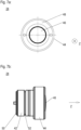
- a perspective view of an inventive ejector piston;
- Figures 4a and 4b:
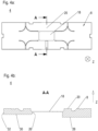
- detailed views of an inventive mould shown in
figure 1 ; - Figures 5a and 5b:
- detailed views of the support element shown in
figure 2 ; - Figures 6:
- a cross-section of the assembled mould; and
- Figures 7a and 7b:
- detailed views of the ejector piston shown in
figure 3 ; - In
figure 1 a preferred embodiment of an inventive formingtool 1 is shown. The formingtool 1 can be used for the production of fibre reinforced plastics using low viscous resin enabling a class A surface without markings due to the inventive demoulding technology. An exemplary production method is resin transfer moulding (RTM). - The forming
tool 1 comprises at least an inventivelower mould 4 that acts together with an upper mould 6. Both moulds 4, 6 are orientated horizontally (in general) and define a cavity in which the product 2 is fabricated. In the shown embodiment, the product 2 is a spineboard. - The cavity is limited by
inner surfaces upper mould 4. Theinner surfaces inner surface 8 of thelower mould 4 forms a bottom of the cavity and theinner surface 10 of the upper mould 6 forms a ceiling of the cavity. The cavity can be opened and closed by moving the upper mould 6 upwards in vertical direction. - Further on, in the shown embodiment the forming
tool 1 has alower base plate 12, asprue block 14, and anupper base plate 16. The positioning and usage of these elements are common, so that a detailed description can be omitted. Further on, the formingtool 1, in particular their elements (4, 6, 12, 14, 16) comprise known supply lines such as, resin injection lines, evacuation lines, ventilation lines, sealings, etc. which are necessary for RTM-processing. - According to the invention the
inner surface 8 of thelower mould 4 has anintegral surface section 18 which is adapted be moved relatively toadjacent surface areas 20 in a demoulding direction z, which is in the shown embodiment in vertical direction from bottom to top. Infigure 1 , theintegral surface section 18 is highlighted by a dash circle, as it is not visible from the top. In the following the term "lifting direction z" is also used for "demoulding direction z". By means of pushing theintegral surface section 18 upwards, any adhesion between the fabricated product 2 and theinner surface 8 is released such that the fabricated product 2 can be taken out easily of the opened cavity from thelower mould 4. If the inventive mould is the upper mould 6, the term "lifting direction z" will also be adequate, as then the demoulding movement of the product 2 will show away from theinner surface 10 of the upper mould 6, in particular downwards, so that the product 2 will be "lifted down" and pushed out of the upper mould 6. - Below the
integral surface section 18, asupport element 22, shown infigure 2 , is positioned. Thesupport element 22 acts as a rest block and avoids any deformation of theintegral surface section 18 caused by stress and pressure acting on the product 2 during fabrication. In addition, thesupport element 22 houses anejector piston 24 shown infigure 3 . - The
ejector piston 24 is adapted to push theintegral surface section 18 in lifting direction z during demoulding. - The
integral surface section 18, thesupport element 22 and thepiston 24 will be descripted in more detailed in the following figures. - As exemplary shown in the bottom view of the
lower mould 4 according tofigure 4a and in the cross-section according tofigure 4b , theintegral surface section 18 has a rectangular shape. It is positioned in the middle of thelower mould 4 so that lifting forces are acting evenly on the product 2 to be demoulded. - The
integral surface section 18 is made by material reduction of thelower mould 4 such that apocket 26 is established which is opened to the bottom side 28 (outer surface which is opposite to the inner surface 8) of thelower mould 4 but closed to upper side (inner surface 8) of thelower mould 4 by thesurface sections 18. In a preferred embodiment, when thelower mould 4 is metallic, the material reduction can be released by milling. - The
surface section 18 is integrally formed with the surroundingareas 20 of theinner surface 8. This means that thesurface section 18 is seamless integrated into theinner surface 8. Looking form above on thelower mould 4, thesurface section 18 cannot be seen due to their seamless integration. Thesurface section 18 consists of the same material as the surrounding surfaces 20. The only difference between thesurface section 18 and the surroundingsurface areas 20 is that thesurface section 18 is material reduced from the back in such a manner that it (the surface section 18) shows elastics characteristics enabling its lifting up relatively to the rigid surroundingsurface areas 20. In other words, theintegral surface section 18 forms an elastic (flexible), seamless integrated membrane that consists of the same material as its surroundingsurface areas 20. - It is important that the
membrane 18 deforms only on an elastic basis of the metal when theejector piston 24 executes a lifting stroke (demoulding stroke). During the lifting stroke, thesurface section 18 only stretches to that extend that the elasticity remains securely within its elastic range. - The maximum lifting stroke, which is the lifting stroke after which plastic deformation of the
surface section 18 occurs, can be calculated by Hooke's calculation
surface section 18, it is recommended to select anejector piston 24 having a smaller maximum lifting stroke if positioned in thesupport element 22 and measured from surface 29 (support surface of thesupport element 22, shown infigures 5a, 5b and 6 ) on which thesurface section 18 rests during fabrication. - In addition, in the
bottom side 28 of the lower mould 4 achannel 30 is provided. Thechannel 30 is opened at its ends and over its entire length to thebottom side 28. It extends between thepocket 26 and aside wall 32 of thelower mould 4. - The
channel 30 has a straight shape and has a smaller height than thepocket 26. It is a kind of straight recess which can be manufactured by milling as well. - In
figures 5a and 5b theexemplary support element 22 is shown in more detail. Preferably, thesupport element 22 is made of the same material as thelower mould 4. It has asupport portion 34 and asupply portion 36. Thesupport portion 34 provides thesupport surface 29 and has a rectangular shape. In particular, the dimensions are such that it fits perfectly in thepocket 26 of the lower mould 4 (seefigure 6 ). That means, thesurface section 18 is fully supported by thesupport portion 34 during fabrication so that any deformation of thesurface section 18 to the underside of thelower mould 4 caused by stress or pressure acting on the product 2 is prevented. The height of thesupport element 22 is equal to the height of thelower pocket 26, so that height compensation is not necessary if thesupport element 18 is introduced and thelower mould 4 rests on thelower base plate 12. - In the middle of the
support surface 29 of thesupport portion 34 anupper recess 38 is provided. Theupper recess 38 is used for housing and guiding theejector piston 24. Theupper recess 38 has a circular shape that correspondence to the outer shape of theejector piston 24. It is opened to thesupport surface 29 and at its bottom opened to asupply line 40. As theupper recess 38 is positioned in the middle of thesupport surface 29, theejector piston 24 will be positioned in the middle (centre) of thesurface section 18 so that a lifting force is distributed evenly over thesurface section 18. If as in the shown embodiment thesurface section 18 is in the middle of thelower mould 4, the lifting force will be distributed not only evenly with respect to thesurface section 18, but also with respect to the entire product 2. - The
supply portion 36 of thesupport element 22 has a longitudinal arm-like shape. Looking from the side, bothportions bottom line 39, whereas thesupply portion 36 has a smaller height than thesupport portion 34. The shape of thesupply portion 36 corresponds to the shape of thechannel 30 so that it fits perfectly in it (seefigure 6 ). In particular both thesupply portion 36 and thechannel 30 has almost the same length. - The
supply portion 36 provides the at least onesupply line 40 that extends from theupper recess 38 to anouter connection area 41 in order to connect the at least one supply line to an energy source. If theejector piston 24 is a hydraulic piston, for instance, the at leastsupply line 40 is used to feed hydraulic oil provided by an hydraulic system to theejector piston 24 in order to lift thesurface section 18 and to return the hydraulic oil back to the hydraulic system. - In
figures 7a and 7b anexemplary ejector piston 24 is shown. The piston has basically a cylindrical shape with ashaft 42 and ahead 44 which is radially enlarged compared to theshaft 42. Its outer shape fits perfectly to theupper recess 38 of thesupport portion 34 of thesupport element 22. In order to optimise the transmission of the lifting force into theintegral surface section 18, the front of thehead 44 has amiddle surface 46 which is slightly convexed outward and surrounded by a flatannular surface 48. - The
ejector piston 24 is pushed upwards by the hydraulic pressure acting on itsback side 50. In order to avoid any leakage, at least one not shown seal ring is inserted in anannular groove 52 of theshaft 42. - According to an inventive method, in order to demould a fabricated product 2, the
integral surface section 18 of theinner surface 8 of thelower mould 4 is moved relatively to theadjacent surface areas 20 in lifting direction by a lifting force acting from below on theintegral surface section 18. The lifting force and in particular the stroke is applied in such a manner that theintegral surface section 18 deforms only elastically, so that after the stroke is terminated, thesurface section 18 goes back in its initial position, where it in surface contact with thesupport portion 34 of thesupport element 22. - Disclosed are a mould of a forming tool, in particular for a forming tool capable to be used for resin transfer moulding processes or injecting moulding processes, wherein an inner surface of the mould which (the inner surface) is adapted to limit on one side a forming tool cavity for a product to be fabricated has an integral surface section which is adapted be moved relatively to adjacent surface areas in a demoulding direction, forming tool having such a mould and a method for demoulding, wherein an integral inner surface section acts as membrane and is moved inside the cavity to push the product out of the mould.
-
- 1
- forming tool
- 2
- product
- 4
- lower mould
- 6
- upper mould
- 8
- inner surface of the lower mould
- 10
- inner surface of the upper mould
- 12
- lower base plate
- 14
- sprue block
- 16
- upper base plate
- 18
- integral surface section (membrane)
- 20
- adjacent / surrounding surface areas
- 22
- support element
- 24
- ejector piston
- 26
- 28
- bottom side
- 29
- support surface
- 30
- channel
- 32
- side wall of the lower mould
- 34
- support portion
- 36
- supply portion
- 38
- upper recess
- 39
- bottom line
- 40
- supply line
- 41
- outer connection area
- 42
- shaft
- 44
- head
- 46
- middle surface
- 48
- annular surface
- 50
- back side
- 52
- annular groove
- z
- demoulding / lifting direction
Claims (9)
- Mould (4) of a forming tool (1), in particular for a forming tool capable to be used for resin transfer moulding processes or injecting moulding processes,
wherein• the mould (4) is adapted to act together with another mould (6) of the forming tool (1) in order to form a cavity for a product (2) to be fabricated,
and wherein• the mould (4) limits on one side the cavity by its inner surface(8),
characterised in that• the inner surface (8) has an integral surface section (18) which is adapted be moved relatively to adjacent surface areas (20) in a demoulding direction (z). - Mould according to claim 1, wherein in the demoulding direction (z) the surface section (18) is material reduced compared to the adjacent surface areas (20).
- Mould according to claim 1 or 2, wherein a support element (22) is provided adapted to be positioned under the surface section (18) in order to support the surface section (18) during processing.
- Mould according to claim 3, wherein the support element (22) has an upper recess (38) for an ejector means (24).
- Mould according to claim 4, wherein the upper recess (38) is positioned such in the support element (22) that it can be positioned in the middle of the surface section (6).
- Mould according to claims 4 or 5, wherein the support element (22) has at least one support portion (34) and at least one supply portion (36), which is material reduced compart to the support portion (34) and in which all required supply lines (40) are provided internally extending between the upper recess (38) in the support portion (34) and an outer supply connection area (4) of the support element (22).
- Mould according to claim 6, wherein in the mould (4) a channel (30) is provided adapted to receive the supply portion (36) of the support element (22) and having the same or almost the same length as the supply portion (36).
- Forming tool (1), in particular a forming tool (1) capable to be used for resin transfer moulding processes or injecting moulding processes, comprising a mould (4) according to any of the preceding claims 1 to 8.
- Method for demoulding, in particular for demoulding a fabricated product (2) from a mould (4) of a forming tool (1), in particular a forming tool capable to be used for resin transfer moulding processes or injecting moulding processes, wherein an inner surface (6) of the mould (4) limits on one side a cavity in which the product (2) is fabricated,
comprising the step:• moving an integral surface section (18) of the inner surface (8) of the mould (4) relatively to adjacent surface areas (20) in demoulding direction (z) by a force acting from the back on the integral surface section (18).
Priority Applications (2)
| Application Number | Priority Date | Filing Date | Title |
|---|---|---|---|
| EP23157344.5A EP4417391A1 (en) | 2023-02-17 | 2023-02-17 | Mould of a forming tool, forming tool and method |
| US18/437,573 US20240278467A1 (en) | 2023-02-17 | 2024-02-09 | Mold of a forming tool, forming tool, and method for demolding |
Applications Claiming Priority (1)
| Application Number | Priority Date | Filing Date | Title |
|---|---|---|---|
| EP23157344.5A EP4417391A1 (en) | 2023-02-17 | 2023-02-17 | Mould of a forming tool, forming tool and method |
Publications (1)
| Publication Number | Publication Date |
|---|---|
| EP4417391A1 true EP4417391A1 (en) | 2024-08-21 |
Family
ID=85283718
Family Applications (1)
| Application Number | Title | Priority Date | Filing Date |
|---|---|---|---|
| EP23157344.5A Pending EP4417391A1 (en) | 2023-02-17 | 2023-02-17 | Mould of a forming tool, forming tool and method |
Country Status (2)
| Country | Link |
|---|---|
| US (1) | US20240278467A1 (en) |
| EP (1) | EP4417391A1 (en) |
Citations (4)
| Publication number | Priority date | Publication date | Assignee | Title |
|---|---|---|---|---|
| FR2846592A1 (en) * | 2002-10-30 | 2004-05-07 | Jean Pierre Duval | Adjustable ejector for plastic or metal component from injection mould has wedge rod connected to threaded dowel for adjusting its length |
| DE102011050976A1 (en) | 2011-06-09 | 2012-12-13 | Georg Fritzmeier Gmbh & Co. Kg | Ejection device for ejecting mold e.g. sheet molding compound (SMC) mold, has ejector pin which is provided in transverse direction with respect to longitudinal axis for ejecting mold |
| DE102013207668A1 (en) | 2013-04-26 | 2014-10-30 | Bayerische Motoren Werke Aktiengesellschaft | Tool for producing a fiber-plastic composite component with at least one vent hole and arranged therein Auswerferstift |
| FR3016824A1 (en) * | 2014-01-29 | 2015-07-31 | Snecma | MOLD, IN PARTICULAR INJECTION MOLD, AND INJECTION MOLDING METHOD USING SUCH A MOLD |
Family Cites Families (3)
| Publication number | Priority date | Publication date | Assignee | Title |
|---|---|---|---|---|
| US3174189A (en) * | 1963-06-17 | 1965-03-23 | Robert W Cutler | Plastic injection mold |
| US6638467B1 (en) * | 1999-08-16 | 2003-10-28 | Green Tokai Co., Ltd. | Molding ejector plate structure and method of ejecting molded articles from mold cavity therewith |
| CN113878803B (en) * | 2021-08-19 | 2025-03-07 | 太仓雅沃汽车科技有限公司 | A vertical injection mold |
-
2023
- 2023-02-17 EP EP23157344.5A patent/EP4417391A1/en active Pending
-
2024
- 2024-02-09 US US18/437,573 patent/US20240278467A1/en active Pending
Patent Citations (4)
| Publication number | Priority date | Publication date | Assignee | Title |
|---|---|---|---|---|
| FR2846592A1 (en) * | 2002-10-30 | 2004-05-07 | Jean Pierre Duval | Adjustable ejector for plastic or metal component from injection mould has wedge rod connected to threaded dowel for adjusting its length |
| DE102011050976A1 (en) | 2011-06-09 | 2012-12-13 | Georg Fritzmeier Gmbh & Co. Kg | Ejection device for ejecting mold e.g. sheet molding compound (SMC) mold, has ejector pin which is provided in transverse direction with respect to longitudinal axis for ejecting mold |
| DE102013207668A1 (en) | 2013-04-26 | 2014-10-30 | Bayerische Motoren Werke Aktiengesellschaft | Tool for producing a fiber-plastic composite component with at least one vent hole and arranged therein Auswerferstift |
| FR3016824A1 (en) * | 2014-01-29 | 2015-07-31 | Snecma | MOLD, IN PARTICULAR INJECTION MOLD, AND INJECTION MOLDING METHOD USING SUCH A MOLD |
Also Published As
| Publication number | Publication date |
|---|---|
| US20240278467A1 (en) | 2024-08-22 |
Similar Documents
| Publication | Publication Date | Title |
|---|---|---|
| US6394779B1 (en) | Molding tool for molding with cylindrical core | |
| CN102537001B (en) | Be attached to functional element and the component assembly of plastic member | |
| CZ303737B6 (en) | Sealing ring | |
| CN101932422A (en) | Coating mold for in-mold molded product and method of forming coating of in-mold molded product | |
| US6689303B2 (en) | Injection molding method using a stacked mold | |
| US20240278467A1 (en) | Mold of a forming tool, forming tool, and method for demolding | |
| CN112517816B (en) | Bidirectional intermittent differential upsetting composite extrusion forming method for outer longitudinal rib cylindrical part | |
| CN112517657B (en) | Two-way differential extrusion forming method of outer longitudinal rib cylindrical parts | |
| CN120921625B (en) | An embedded injection mold | |
| CN109676000B (en) | A viscous medium external pressure forming device for large curvature thin-walled components | |
| CN112517658B (en) | Bidirectional differential extrusion forming die for external longitudinal rib cylindrical part | |
| US20210018047A1 (en) | Constant velocity universal joint boot | |
| KR20100009729A (en) | Press mold | |
| US3519280A (en) | Piston bearing and sealing means | |
| US20050287246A1 (en) | Molding machine and locking mechanism for securing tie bars | |
| CS223857B2 (en) | Method of casting and facility for executing the same | |
| CN219727051U (en) | One-time forming die for plastic pipe fitting and injection molding system | |
| US20130171290A1 (en) | Mold-Tool System having Actuator Assembly Including Piston Assembly and Flexible Diaphragm Assembly | |
| CN211941892U (en) | Novel valve needle structure for pouring gate sealing glue | |
| CN112122638B (en) | Sealing piston for a hydraulic expansion clamping device and expansion clamping device | |
| CN212072820U (en) | Novel ejection mechanism of TPE flexible glue mould capable of realizing mass production | |
| CN221417146U (en) | Barrel-type prepreg forming die | |
| CN223671687U (en) | A sealing ring grasping and implantation device | |
| CN219427379U (en) | Ejection structure of die product | |
| CN120902206B (en) | Mold and injection molding apparatus |
Legal Events
| Date | Code | Title | Description |
|---|---|---|---|
| PUAI | Public reference made under article 153(3) epc to a published international application that has entered the european phase |
Free format text: ORIGINAL CODE: 0009012 |
|
| STAA | Information on the status of an ep patent application or granted ep patent |
Free format text: STATUS: THE APPLICATION HAS BEEN PUBLISHED |
|
| AK | Designated contracting states |
Kind code of ref document: A1 Designated state(s): AL AT BE BG CH CY CZ DE DK EE ES FI FR GB GR HR HU IE IS IT LI LT LU LV MC ME MK MT NL NO PL PT RO RS SE SI SK SM TR |
|
| STAA | Information on the status of an ep patent application or granted ep patent |
Free format text: STATUS: REQUEST FOR EXAMINATION WAS MADE |
|
| 17P | Request for examination filed |
Effective date: 20250221 |