EP4417352A1 - Band saw blade and manufacturing method for band saw blade - Google Patents
Band saw blade and manufacturing method for band saw blade Download PDFInfo
- Publication number
- EP4417352A1 EP4417352A1 EP22880727.7A EP22880727A EP4417352A1 EP 4417352 A1 EP4417352 A1 EP 4417352A1 EP 22880727 A EP22880727 A EP 22880727A EP 4417352 A1 EP4417352 A1 EP 4417352A1
- Authority
- EP
- European Patent Office
- Prior art keywords
- tooth
- coat layer
- saw blade
- band saw
- teeth
- Prior art date
- Legal status (The legal status is an assumption and is not a legal conclusion. Google has not performed a legal analysis and makes no representation as to the accuracy of the status listed.)
- Granted
Links
Images





Classifications
-
- B—PERFORMING OPERATIONS; TRANSPORTING
- B23—MACHINE TOOLS; METAL-WORKING NOT OTHERWISE PROVIDED FOR
- B23D—PLANING; SLOTTING; SHEARING; BROACHING; SAWING; FILING; SCRAPING; LIKE OPERATIONS FOR WORKING METAL BY REMOVING MATERIAL, NOT OTHERWISE PROVIDED FOR
- B23D61/00—Tools for sawing machines or sawing devices; Clamping devices for these tools
- B23D61/12—Straight saw blades; Strap saw blades
- B23D61/127—Straight saw blades; Strap saw blades of special material
-
- B—PERFORMING OPERATIONS; TRANSPORTING
- B23—MACHINE TOOLS; METAL-WORKING NOT OTHERWISE PROVIDED FOR
- B23D—PLANING; SLOTTING; SHEARING; BROACHING; SAWING; FILING; SCRAPING; LIKE OPERATIONS FOR WORKING METAL BY REMOVING MATERIAL, NOT OTHERWISE PROVIDED FOR
- B23D61/00—Tools for sawing machines or sawing devices; Clamping devices for these tools
- B23D61/12—Straight saw blades; Strap saw blades
-
- B—PERFORMING OPERATIONS; TRANSPORTING
- B23—MACHINE TOOLS; METAL-WORKING NOT OTHERWISE PROVIDED FOR
- B23D—PLANING; SLOTTING; SHEARING; BROACHING; SAWING; FILING; SCRAPING; LIKE OPERATIONS FOR WORKING METAL BY REMOVING MATERIAL, NOT OTHERWISE PROVIDED FOR
- B23D65/00—Making tools for sawing machines or sawing devices for use in cutting any kind of material
Definitions
- the present disclosure relates to a band saw blade and a method for manufacturing the band saw blade.
- Patent Literature 1 discloses a method for coating a band saw blade in a coating device by winding the band saw blade into a spiral coil shape in order to coat a hard material on the tooth group of the band saw blade.
- Patent Literature 1 Japanese Patent NO. 5174467
- Patent Literature 1 is a general coating method for coating a band saw blade, and is performed at the final stage of the manufacturing process for the band saw blade.
- this method when the band saw blade is wound into a spiral coil shape, a band-like spacer is lapped and wound together with the band saw blade in order to form a gap between the adjacent tooth groups in a radial direction. Since this gap is formed, it is possible to perform coating on the tooth groups well.
- the tooth groups of the band saw blade have set teeth which are set in the left-right direction which is the thickness direction
- the straight teeth are processed into the set teeth by set processing, and then coating on the tooth groups is performed.
- An aspect of the present disclosure is a band saw blade comprising: a body portion having a band-like and an endless shape; a tooth portion in which a tooth group, which is a set of a predetermined number of teeth including a set tooth, is repeatedly formed on one edge side of the body portion; and a coat layer which is formed on a surface of the teeth of the tooth portion, wherein the set tooth has a first indentation portion as a recessed portion in the coat layer on an outer surface in a set direction, and thickness of the coat layer in the recessed portion of the first indentation portion is thinner than that of the coat layer in portions other than the recessed portion.
- the coat layer is formed prior to set processing of the set tooth, and thus there is no uneven thickness of the coat layer in the set tooth.
- An aspect of the present disclosure is a method for manufacturing a band saw blade which is provided with a body portion having a band-like and an endless shape; a tooth portion in which a tooth group, which is a set of a predetermined number of teeth including a set tooth, is repeatedly formed on one edge side of the body portion; and a coat layer which is formed on a surface of the teeth of the tooth portion, the method comprising: performing a coat layer formation step of forming a coat layer on the teeth of an intermediate blade in which the teeth are all straight teeth, and then performing set processing of setting and forming a predetermined tooth into the set tooth.
- an effect is obtained in which there is no uneven thickness of the coat layer in the teeth of the band saw blade, especially in the set teeth.
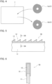
- FIG. 1A is a two-directional view illustrating a side surface and an upper surface of a first intermediate blade 1A used for manufacturing a band saw blade 1 according to a present embodiment.
- FIG. 1B is a two-directional view illustrating a side surface and an upper surface of a spacer 2 used for manufacturing the band saw blade 1 according to the present embodiment.
- the band saw blade 1 is made of a long band-shaped first intermediate blade 1A, and passes through a second intermediate blade 1B and a third intermediate blade 1C, which are intermediate bodies obtained as the manufacturing process progresses, and then is formed by endlessly joining the third intermediate blade 1C which is cut into pieces having a predetermined length.
- FIG. 2 is a plan view illustrating a coil body C in which the first intermediate blade 1A and the spacer 2 are lapped and wound.
- FIG. 3 is an enlarged view of F3 region in FIG. 2 .
- FIG. 4 is a schematic diagram for explaining coating processing performed on the coil body C by a coating device 7.
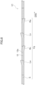
- FIG. 5 is a side view illustrating a second intermediate blade 1B in which a coat layer 13 is formed on a tooth portion 12.
- FIG. 6 is a cross-sectional view at position S6-S6 in FIG. 5 .
- FIG. 7A is a diagram for explaining set processing for the second intermediate blade 1B, and is a cross-sectional view illustrating a state immediately before the processing.
- FIG. 7B is a diagram for explaining the set processing for the second intermediate blade 1B, and is a cross-sectional view illustrating a state during the processing.
- FIG. 8 is a top view illustrating a third intermediate blade 1C in which the second intermediate blade 1B is subjected to set processing.
- FIG. 9 is a diagram for explaining a joining process in which the third intermediate blade 1C is endlessly joined to form the band saw blade 1.
- a first intermediate blade 1A having a predetermined length is prepared as a material and a spacer 2 having a length equivalent to that of the first intermediate blade 1A is prepared as a manufacturing jig.
- the first intermediate blade 1A includes a long band-shaped body portion 11, and a tooth portion 12 formed on one edge side (upper edge side) of the body portion 11.
- the tooth portion 12 has a plurality of teeth 12a formed continuously in the longitudinal direction of the body portion 11.
- the teeth 12a are straight teeth.
- the spacer 2 is a long band-shaped member made of metal.
- the spacer 2 is slightly smaller in width than the body portion 11 of the first intermediate blade 1A, and the thickness thereof is illustrated as a thickness L2.
- the first intermediate blade 1A and the spacer 2 are lapped with edge portions on the opposite side of the tooth portion 12 aligned, and the coil body C is formed by lapping and winding the first intermediate blade 1A and the spacer 2 into a spiral coil shape.
- the first intermediate blade 1A is illustrated as a solid line
- the spacer 2 is illustrated as a dash-dotted line.
- the coil body C is lapped and wound into a spiral coil shape with the spacers 2 interposed between the adjacent first intermediate blades 1A in the radial direction. Since the teeth 12a of the first intermediate blades 1A are all straight teeth, the smallest gap La between the adjacent first intermediate blades 1A in the radial direction is a gap between the body portions 11, and is the thickness L2 of the spacer 2.
- the coil body C is put into the coating device 7 to perform coating processing.
- the coil body C before the coating processing is referred to as a pre-processed coil body Ca
- the coil body C after the coating processing is referred to as a post-processed coil body Cb.
- a method of coating processing is performed by a PVD (physical vapor deposition) method; however, the method is not limited thereto.
- a method of the coating processing may be performed by a CVD (chemical vapor deposition) method.
- a range of the coating processing in the first intermediate blade 1A is the surface of the tooth portion 12, which is the portion of the preprocess coil body Ca which is not in contact with the spacer 2.
- a difference in the thickness of the deposited layer is generated between the shadowed portion and the unshadowed portion, resulting in the formation of unevenness.
- the post-processed coil body Cb is taken out to unwind the winding of the coil body Cb.
- the second intermediate blade 1B is obtained in which the coating processing is performed on the tooth portion 12 of the first intermediate blade 1A.
- a coat layer 13 (a halftone dot portion) is formed, by coating processing, in such a way as to straddle the tooth portion 12 with which the spacer 2 is not in contact and the edge portion on the tooth portion 12 side in the body portion 11.
- the coat layer 13 may be, for example, a layer of titanium nitride (TiN) or titanium aluminum nitride (TiAlN), or a layer of carbon nitride (TiCN) or chromium nitride (CrN), or a combination thereof.
- set processing is performed in which predetermined teeth among the teeth 12a, which are a plurality of straight teeth of the second intermediate blade 1B, are set to the left or right using a set tooth machine 8 to form set teeth.
- the set tooth machine 8 has a fixing unit 81 for pinching and supporting the second intermediate blade 1B in the thickness direction, and a processing unit 82 for locally hitting the side surface of the tooth 12a and pushing the tooth 12a in the thickness direction indicated by an arrow DR1.
- the fixing unit 81 of the set tooth machine 8 pinches and fixes the body portion 11 such that the tooth portion 12 of the second intermediate blade 1B protrudes and is exposed from the fixing unit 81. Thereafter, as illustrated in FIG. 7B , the processing unit 82 pushes one side of the tooth 12a in the thickness direction, bends and sets the tooth 12a to the other side as illustrated by an arrow DR2.
- This set processing is performed in either the left direction or the right direction on predetermined teeth of the second intermediate blade 1B by the set tooth machine 8, thereby obtaining the third intermediate blade 1C illustrated in FIG. 8 .
- the tooth portion 12 of the third intermediate blade 1C is formed such that a set of five teeth which are formed continuously constitutes one tooth group TG and the tooth group TG is repeatedly formed in the longitudinal direction.
- the tooth group TG illustrated in FIG. 8 is a set of a predetermined number of teeth including set teeth.
- the tooth group TG is a set of five teeth: a right set tooth Rw, a left set tooth Ln, a right set tooth Rn, a left set tooth Lw, and a straight tooth S when seen from the cutting direction (arrow DR3) side.
- the set value of the left set tooth Lw and the right set tooth Rw is greater than that of the left set tooth Ln and the right set tooth Rn.
- the tooth group TG is not limited to the configuration illustrated in FIG. 8 .
- both ends of the body portion 11 are welded at the joint portion Pm where both ends of the body portion 11 are abutted against each other in the third intermediate blade 1C.
- the band saw blade 1 having a band-like and an endless shape is obtained.
- the coating processing is performed on all of the straight teeth. Accordingly, unlike in the case where the coating processing is performed on the set teeth, there is no difference in the thickness of the coat layer between the inner surface which is a shadow in the set direction and the outer surface which is a front surface in the set direction, resulting in the formation of no unevenness. That is, according to the method for manufacturing the band saw blade 1, the coat layer 13 becomes uniform in thickness in the coating range.
- the band saw blade 1 is manufactured by set processing subsequent to forming the coat layer 13 on the surface of the teeth 12a. For this reason, in the set processing, the fixing unit 81 and the processing unit 82 of the set tooth machine 8 are pushed from the top of the coat layer 13, and thus an characteristic indentation portion, which is different from the conventional one, is formed at the edge portions of the processing unit 82 and the fixing unit 81.
- the indentation portion will be described with reference to FIG. 10A, FIG. 10B , FIG. 11A, FIG. 11B and FIG. 11C , using the right set tooth Rw which is set in the right direction as an example.
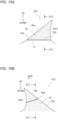
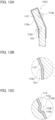
- FIG. 10A is a right side view illustrating a surface state of the tooth 12a in the band saw blade 1
- FIG. 10B is a left side view illustrating the surface state of the tooth 12a in the band saw blade 1.
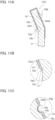
- FIG. 11A is a cross-sectional view illustrating a cross section of the tooth 12a in the band saw blade 1.
- FIG. 11B is an enlarged view of an indentation portion T81 in FIG. 11A
- FIG. 11C is an enlarged view of an indentation portion T82 in FIG. 11A .
- the indentation portion T81 (the second indentation portion T81) by means of the fixing unit 81 is formed at the root portion of the right side surface which is an inner surface 12a1 of the tooth 12a of the right set tooth Rw in the set direction.
- the indentation portion T81 is clearly and visually recognized over the entire longitudinal direction of the tooth 12a in a straight line extending in the longitudinal direction of the body portion 11.
- the indentation portion T82 (first indentation portion T82) by means of the processing unit 82 is formed at the center portion of the left side surface in the tooth height direction (up-down direction) which is an outer surface 12a2 of the tooth 12a of the right set tooth Rw in the set direction.
- the indentation portion T82 is clearly and visually recognized over the entire longitudinal direction of the tooth 12a in a straight line inclined in such a way that the cutting direction AR3 side faces downward.
- the indentation portion T81, the indentation portion T82, and the coat layer 13 have the following characteristics (A), (B), and (C) by performing a coat layer forming process for forming the coat layer 13 on the tooth 12a, and then performing a set processing step for performing the set processing .
- the coat layer 13 a portion of the region on the surface of the tooth 12a from the bent portion 12c to the body portion 11 side is peeled off due to friction with the fixing unit 81 or the like, and thus the formation density of the coat layer 13 is in a low state (In FIG. 10A, FIG. 10B , FIG.
- a halftone dot portion in the coat layer 13 is not illustrated) . That is, the coat layer 13 has a different density between the tooth tip side and the body portion side with the indentation portion T81 as a boundary. The indentation portion T81 formed on the surface of the tooth 12a is clearly and visually recognized by pushing the processing unit 82 against the coat layer 13 in addition to this difference.
- a recessed portion 12b is formed by the processing unit 82. For this reason, the coat layer 13b of the recessed portion 12b is compressed and is smaller in thickness (is thinner) than the other portions of the coat layer 13 (the portions other than the recessed portion).
- the recessed portion 12b is formed by the processing unit 82. For this reason, the indentation portion T82 visually recognized clearly on the surface of the coat layer 13 is formed.
- the indentation portions T181 and T182 formed on a band saw blade 101 of a comparative example are those illustrated in FIG. 12A, FIG. 12B , FIG. 13A, FIG. 13B, and FIG. 13C .
- the band saw blade 101 of the comparative example is manufactured by a conventional manufacturing method in which coating processing is performed on set teeth after forming the set teeth.
- FIG. 12A is a right side view illustrating a surface state of the tooth 112a in the band saw blade 101 of the comparative example
- FIG. 12B is a left side view illustrating the surface state of the tooth 112a in the band saw blade 101 of the comparative example.
- FIG. 12A is a right side view illustrating a surface state of the tooth 112a in the band saw blade 101 of the comparative example
- FIG. 12B is a left side view illustrating the surface state of the tooth 112a in the band saw blade 101 of the comparative example.
- FIG. 13A is a cross-sectional view illustrating a cross section of the tooth 112a in the band saw blade 101 of the comparative example
- FIG. 13B is an enlarged view of the indentation portion T181 in FIG. 13A
- FIG. 13C is an enlarged view of the indentation portion T182 in FIG. 13A .
- the indentation portion T181 by means of the fixing unit 81 is formed at the root portion of the right side surface of the tooth 112a of the right set tooth Rw.
- the indentation portion T181 is visually recognized slightly on a portion of the tooth 112a in some cases, in a straight line extending in the longitudinal direction of the body portion 11.
- the indentation portion T182 by means of the processing unit 82 is formed at the center portion of the left side surface of the tooth 112a of the right set tooth Rw in the tooth height direction (up-down direction).
- the indentation portion T182 is visually recognized, in some cases, slightly on a portion of the tooth 112a, in a straight line inclined in such a way that the cutting direction AR3 side faces downward.
- the indentation portion T181, the indentation portion T182, and the coat layer 113 have the following characteristics (D), (E), and (F) by forming the coat layer 113 on the tooth 112a, and then performing the set processing.
- D The coat layer 113 is formed after a bent portion 112c is formed on the surface of the tooth 112a by the fixing unit 81. For this reason, the formation density of the coat layer 113 is almost the same on the blade edge side and the body portion side with the bent portion 112c as a boundary.
- the coat layer 113 is formed.
- the coat layer 13b of the recessed portion 112b has almost the same thickness as that of the other portions of the coat layer 113.
- the coat layer 113 is formed so as to cover the bent portion 112c and the recessed portion 112b. For this reason, the bent portion 112c and the recessed portion 112b are hidden in the coat layer 113, and the indentation portions T181 and T182 are partially difficult or impossible to be visually recognized in some cases.
- the band saw blade 1 of the present embodiment has a characteristic structure different from that of the conventional product, even in the manufactured product itself, by performing the set processing after forming the coat layer 13. That is, (A), (B), and (C), which are characteristics of the band saw blade 1, are differences corresponding to (D), (E), and (F) of the band saw blade 101 of the comparative example, respectively, and the band saw blade 1 can be distinguished from other band saw blades by recognizing such differences as characteristic structures unique to the band saw blade 1.
- a band saw blade 1 of the present embodiment includes: a body portion 11 having a band-like and an endless shape; a tooth portion 12 in which a tooth group TG, which is a set of a predetermined number of teeth 12a including a set tooth Rw, is repeatedly formed on one edge side of the body portion 11; and a coat layer 13 which is formed on a surface of the teeth 12a of the tooth portion 12, in which the set tooth Rw has a first indentation portion T82 as a recessed portion 12b in the coat layer 13 on an outer surface 12a2 in a set direction, and thickness of the coat layer 13 in the recessed portion 12b of the first indentation portion T82 is thinner than that of the coat layer 13 in portions other than the recessed portion 12b.
- the set tooth Rw may have a second indentation portion T81 as a bent portion 12c in the coat layer 13 on an inner surface 12a1 in the set direction, and the coat layer 13 may have a lower formation density on a body portion 11 side than on a tooth tip side with the second indentation portion T81 as a boundary.
- the coat layer 13 of uniform thickness is formed on a portion necessary for cutting by coating processing in a manufacturing process.
- a method for manufacturing a band saw blade according to the present embodiment which is provided with a looped body portion 11 having a band-like shape; a tooth portion 12 in which a tooth group TG, which is a set of a predetermined number of teeth 12a including a set tooth Rw, is repeatedly formed on one edge side of the body portion 11; and a coat layer 13 which is formed on a surface of the teeth 12a of the tooth portion 12, the method includes: performing a coat layer formation step of forming a coat layer 13 on the teeth 12a of an intermediate blade 1A in which the teeth 12a are all straight teeth S, and then performing set processing of setting and forming a predetermined tooth 12a into the set tooth Rw.
- the coating processing which is a coat layer formation step is performed only on the straight teeth. This makes it possible to form a coat layer of uniform thickness.
- the method for manufacturing the band saw blade of one aspect may have the coat layer formation step in which the intermediate blade 1A and the band-like spacer 2 are lapped and wound so as to expose the tooth portion 12, thereby forming a coil body C having a spiral coil shape, and the formed coil body C is put into the coating device 7 to form the coat layer 13.
- the set teeth and the straight teeth in the tooth group TG of the band saw blade 1 are not limited to the structure of the present embodiment.
- the material and formation method of the coat layer 13 are not limited to the ones of the present embodiment.
- the thickness of the spacer 2 can be set as small as possible within the range in which it is possible to obtain a coat layer 13 of good quality according to the type of the band saw blade 1 and the conditions of the coating processing thereof. This makes it possible to increase the length of the saw blade which can form the coat layer in one coating processing.
Landscapes
- Engineering & Computer Science (AREA)
- Mechanical Engineering (AREA)
- Bending Of Plates, Rods, And Pipes (AREA)
Abstract
Description
- The present disclosure relates to a band saw blade and a method for manufacturing the band saw blade.
-
Patent Literature 1 discloses a method for coating a band saw blade in a coating device by winding the band saw blade into a spiral coil shape in order to coat a hard material on the tooth group of the band saw blade. - [Patent Literature 1]
Japanese Patent NO. 5174467 - The method described in
Patent Literature 1 is a general coating method for coating a band saw blade, and is performed at the final stage of the manufacturing process for the band saw blade. In this method, when the band saw blade is wound into a spiral coil shape, a band-like spacer is lapped and wound together with the band saw blade in order to form a gap between the adjacent tooth groups in a radial direction. Since this gap is formed, it is possible to perform coating on the tooth groups well. - Meanwhile, conventionally, when the tooth groups of the band saw blade have set teeth which are set in the left-right direction which is the thickness direction, the straight teeth are processed into the set teeth by set processing, and then coating on the tooth groups is performed. In this case, there may be a difference in the thickness of a coat layer formed by coating between the inner surface, which is the inner side of the set teeth in the set direction, and the outer surface, which is the outer side of the set teeth in the set direction. That is, since the inner surface is a shadow of the inclination in the set direction, the coat layer formed on the inner surface tends to be smaller in thickness than the coat layer formed on the outer surface which is a front side of the inclination in the set direction. Therefore, an uneven thickness of the coat layer is generated in the teeth of the band saw blade, especially in the set teeth. Therefore, a band saw blade and a method for manufacturing the band saw blade without an uneven thickness of the coat layer have been desired even if the band saw blade has set teeth.
- An aspect of the present disclosure is a band saw blade comprising: a body portion having a band-like and an endless shape; a tooth portion in which a tooth group, which is a set of a predetermined number of teeth including a set tooth, is repeatedly formed on one edge side of the body portion; and a coat layer which is formed on a surface of the teeth of the tooth portion, wherein the set tooth has a first indentation portion as a recessed portion in the coat layer on an outer surface in a set direction, and thickness of the coat layer in the recessed portion of the first indentation portion is thinner than that of the coat layer in portions other than the recessed portion.
- According to an aspect of the present disclosure, it is apparent that the coat layer is formed prior to set processing of the set tooth, and thus there is no uneven thickness of the coat layer in the set tooth.
- An aspect of the present disclosure is a method for manufacturing a band saw blade which is provided with a body portion having a band-like and an endless shape; a tooth portion in which a tooth group, which is a set of a predetermined number of teeth including a set tooth, is repeatedly formed on one edge side of the body portion; and a coat layer which is formed on a surface of the teeth of the tooth portion, the method comprising: performing a coat layer formation step of forming a coat layer on the teeth of an intermediate blade in which the teeth are all straight teeth, and then performing set processing of setting and forming a predetermined tooth into the set tooth.
- According to an aspect of the present disclosure, since the coat layer is formed prior to set processing of the set tooth, there is no uneven thickness of the coat layer in the set tooth.
- According to an aspect of the present disclosure, an effect is obtained in which there is no uneven thickness of the coat layer in the teeth of the band saw blade, especially in the set teeth.
-
- [
FIG. 1A] FIG. 1A is a two-directional view illustrating a side surface and an upper surface of a firstintermediate blade 1A used for manufacturing aband saw blade 1 according to a present embodiment. - [
FIG. 1B] FIG. 1B is a two-directional view illustrating a side surface and an upper surface of aspacer 2 used for manufacturing theband saw blade 1 according to the present embodiment. - [
FIG. 2] FIG. 2 is a plan view illustrating a coil body C in which the firstintermediate blade 1A and thespacer 2 are lapped and wound. - [
FIG. 3] FIG. 3 is an enlarged view of F3 region inFIG. 2 . - [
FIG. 4] FIG. 4 is a schematic diagram for explaining coating processing performed on the coil body C by acoating device 7. - [
FIG. 5] FIG. 5 is a side view illustrating a secondintermediate blade 1B in which acoat layer 13 is formed on atooth portion 12. - [
FIG. 6] FIG. 6 is a cross-sectional view at position S6-S6 inFIG. 5 . - [
FIG. 7A] FIG. 7A is a diagram for explaining set processing for the secondintermediate blade 1B, and is a cross-sectional view illustrating a state immediately before the processing. - [
FIG. 7B] FIG. 7B is a diagram for explaining the set processing for the secondintermediate blade 1B, and is a cross-sectional view illustrating a state during the processing. - [
FIG. 8] FIG. 8 is a top view illustrating a thirdintermediate blade 1C in which the secondintermediate blade 1B is subjected to set processing. - [
FIG. 9] FIG. 9 is a diagram for explaining a joining process in which the thirdintermediate blade 1C is joined into a loop shape to form theband saw blade 1. - [
FIG. 10A] FIG. 10A is a right side view illustrating a surface state of a main portion of atooth 12a in theband saw blade 1. - [
FIG. 10B] FIG. 10B is a left side view illustrating a surface state of thetooth 12a in theband saw blade 1. - [
FIG. 11A] FIG. 11A is a cross-sectional view illustrating a cross section of thetooth 12a in theband saw blade 1. - [
FIG. 11B] FIG. 11B is an enlarged view of an indentation portion T81 inFIG. 11A . - [
FIG. 11C] FIG. 11C is an enlarged view of an indentation portion T82 inFIG. 11A . - [
FIG. 12A] FIG. 12A is a right side view illustrating a surface state of atooth 112a in aband saw blade 101 of a comparative example. - [
FIG. 12B] FIG. 12B is a left side view illustrating the surface state of thetooth 112a in the band sawblade 101 of the comparative example. - [
FIG. 13A] FIG. 13A is a cross-sectional view illustrating a cross section of thetooth 112a in theband saw blade 101 of the comparative example. - [
FIG. 13B] FIG. 13B is an enlarged view of an indentation portion T181 inFIG. 13A . - [
FIG. 13C] FIG. 13C is an enlarged view of an indentation portion T182 inFIG. 13A . -
FIG. 1A is a two-directional view illustrating a side surface and an upper surface of a firstintermediate blade 1A used for manufacturing aband saw blade 1 according to a present embodiment.FIG. 1B is a two-directional view illustrating a side surface and an upper surface of aspacer 2 used for manufacturing the band sawblade 1 according to the present embodiment. The band sawblade 1 is made of a long band-shaped firstintermediate blade 1A, and passes through a secondintermediate blade 1B and a thirdintermediate blade 1C, which are intermediate bodies obtained as the manufacturing process progresses, and then is formed by endlessly joining the thirdintermediate blade 1C which is cut into pieces having a predetermined length. - First, a method for manufacturing the band saw
blade 1 will be described with reference toFIG. 1 andFIGS. 2 to 9 .FIG. 2 is a plan view illustrating a coil body C in which the firstintermediate blade 1A and thespacer 2 are lapped and wound.FIG. 3 is an enlarged view of F3 region inFIG. 2 .FIG. 4 is a schematic diagram for explaining coating processing performed on the coil body C by acoating device 7.FIG. 5 is a side view illustrating a secondintermediate blade 1B in which acoat layer 13 is formed on atooth portion 12.FIG. 6 is a cross-sectional view at position S6-S6 inFIG. 5 .FIG. 7A is a diagram for explaining set processing for the secondintermediate blade 1B, and is a cross-sectional view illustrating a state immediately before the processing.FIG. 7B is a diagram for explaining the set processing for the secondintermediate blade 1B, and is a cross-sectional view illustrating a state during the processing.FIG. 8 is a top view illustrating a thirdintermediate blade 1C in which the secondintermediate blade 1B is subjected to set processing.FIG. 9 is a diagram for explaining a joining process in which the thirdintermediate blade 1C is endlessly joined to form the band sawblade 1. - First, a first
intermediate blade 1A having a predetermined length is prepared as a material and aspacer 2 having a length equivalent to that of the firstintermediate blade 1A is prepared as a manufacturing jig. As illustrated inFIG. 1A , the firstintermediate blade 1A includes a long band-shapedbody portion 11, and atooth portion 12 formed on one edge side (upper edge side) of thebody portion 11. Thetooth portion 12 has a plurality ofteeth 12a formed continuously in the longitudinal direction of thebody portion 11. Theteeth 12a are straight teeth. As illustrated in FIG. 2B, thespacer 2 is a long band-shaped member made of metal. Thespacer 2 is slightly smaller in width than thebody portion 11 of the firstintermediate blade 1A, and the thickness thereof is illustrated as a thickness L2. - Next, as illustrated in
FIG. 2 , the firstintermediate blade 1A and thespacer 2 are lapped with edge portions on the opposite side of thetooth portion 12 aligned, and the coil body C is formed by lapping and winding the firstintermediate blade 1A and thespacer 2 into a spiral coil shape. InFIG. 2 , for the sake of simplification, the firstintermediate blade 1A is illustrated as a solid line, and thespacer 2 is illustrated as a dash-dotted line. As illustrated inFIG. 3 , the coil body C is lapped and wound into a spiral coil shape with thespacers 2 interposed between the adjacent firstintermediate blades 1A in the radial direction. Since theteeth 12a of the firstintermediate blades 1A are all straight teeth, the smallest gap La between the adjacent firstintermediate blades 1A in the radial direction is a gap between thebody portions 11, and is the thickness L2 of thespacer 2. - As illustrated in
FIG. 4 , the coil body C is put into thecoating device 7 to perform coating processing. Hereinafter, the coil body C before the coating processing is referred to as a pre-processed coil body Ca, and the coil body C after the coating processing is referred to as a post-processed coil body Cb. - A method of coating processing is performed by a PVD (physical vapor deposition) method; however, the method is not limited thereto. For example, a method of the coating processing may be performed by a CVD (chemical vapor deposition) method. At least, a range of the coating processing in the first
intermediate blade 1A is the surface of thetooth portion 12, which is the portion of the preprocess coil body Ca which is not in contact with thespacer 2. In addition, in the range of the coating processing, a difference in the thickness of the deposited layer is generated between the shadowed portion and the unshadowed portion, resulting in the formation of unevenness. - After the coating processing is performed under predetermined conditions, the post-processed coil body Cb is taken out to unwind the winding of the coil body Cb. From the post-processed coil body Cb, the second
intermediate blade 1B is obtained in which the coating processing is performed on thetooth portion 12 of the firstintermediate blade 1A. - As illustrated in
FIGS. 5 and 6 , in the secondintermediate blade 1B, a coat layer 13 (a halftone dot portion) is formed, by coating processing, in such a way as to straddle thetooth portion 12 with which thespacer 2 is not in contact and the edge portion on thetooth portion 12 side in thebody portion 11. The coat layer 13 (seeFIG. 5 ) may be, for example, a layer of titanium nitride (TiN) or titanium aluminum nitride (TiAlN), or a layer of carbon nitride (TiCN) or chromium nitride (CrN), or a combination thereof. - Next, set processing is performed in which predetermined teeth among the
teeth 12a, which are a plurality of straight teeth of the secondintermediate blade 1B, are set to the left or right using aset tooth machine 8 to form set teeth. As illustrated inFIG. 7A , theset tooth machine 8 has a fixingunit 81 for pinching and supporting the secondintermediate blade 1B in the thickness direction, and aprocessing unit 82 for locally hitting the side surface of thetooth 12a and pushing thetooth 12a in the thickness direction indicated by an arrow DR1. - The fixing
unit 81 of theset tooth machine 8 pinches and fixes thebody portion 11 such that thetooth portion 12 of the secondintermediate blade 1B protrudes and is exposed from the fixingunit 81. Thereafter, as illustrated inFIG. 7B , theprocessing unit 82 pushes one side of thetooth 12a in the thickness direction, bends and sets thetooth 12a to the other side as illustrated by an arrow DR2. - This set processing is performed in either the left direction or the right direction on predetermined teeth of the second
intermediate blade 1B by theset tooth machine 8, thereby obtaining the thirdintermediate blade 1C illustrated inFIG. 8 . For example, thetooth portion 12 of the thirdintermediate blade 1C is formed such that a set of five teeth which are formed continuously constitutes one tooth group TG and the tooth group TG is repeatedly formed in the longitudinal direction. The tooth group TG illustrated inFIG. 8 is a set of a predetermined number of teeth including set teeth. Specifically, the tooth group TG is a set of five teeth: a right set tooth Rw, a left set tooth Ln, a right set tooth Rn, a left set tooth Lw, and a straight tooth S when seen from the cutting direction (arrow DR3) side. The set value of the left set tooth Lw and the right set tooth Rw is greater than that of the left set tooth Ln and the right set tooth Rn. The tooth group TG is not limited to the configuration illustrated inFIG. 8 . - Next, as illustrated in
FIG. 9 , both ends of thebody portion 11 are welded at the joint portion Pm where both ends of thebody portion 11 are abutted against each other in the thirdintermediate blade 1C. As a result, the band sawblade 1 having a band-like and an endless shape is obtained. - In the method for manufacturing the band saw
blade 1 described above, all theteeth 12a of thetooth portion 12 are straight teeth at the time of coating processing. After the coating processing, the set processing is performed to form the predetermined straight teeth into the set teeth. For this reason, thespacer 2 to be lapped and wound by the coil body C has the thickness L2. In this way, in the method for manufacturing the band sawblade 1, the coating processing is performed on all of the straight teeth. Accordingly, unlike in the case where the coating processing is performed on the set teeth, there is no difference in the thickness of the coat layer between the inner surface which is a shadow in the set direction and the outer surface which is a front surface in the set direction, resulting in the formation of no unevenness. That is, according to the method for manufacturing the band sawblade 1, thecoat layer 13 becomes uniform in thickness in the coating range. - As described above, the band saw
blade 1 is manufactured by set processing subsequent to forming thecoat layer 13 on the surface of theteeth 12a. For this reason, in the set processing, the fixingunit 81 and theprocessing unit 82 of theset tooth machine 8 are pushed from the top of thecoat layer 13, and thus an characteristic indentation portion, which is different from the conventional one, is formed at the edge portions of theprocessing unit 82 and the fixingunit 81. The indentation portion will be described with reference toFIG. 10A, FIG. 10B ,FIG. 11A, FIG. 11B and FIG. 11C , using the right set tooth Rw which is set in the right direction as an example. -
FIG. 10A is a right side view illustrating a surface state of thetooth 12a in the band sawblade 1, andFIG. 10B is a left side view illustrating the surface state of thetooth 12a in the band sawblade 1.FIG. 11A is a cross-sectional view illustrating a cross section of thetooth 12a in the band sawblade 1.FIG. 11B is an enlarged view of an indentation portion T81 inFIG. 11A, and FIG. 11C is an enlarged view of an indentation portion T82 inFIG. 11A . - As illustrated in
FIG. 10A ,FIG. 11A, and FIG. 11B , the indentation portion T81 (the second indentation portion T81) by means of the fixingunit 81 is formed at the root portion of the right side surface which is an inner surface 12a1 of thetooth 12a of the right set tooth Rw in the set direction. The indentation portion T81 is clearly and visually recognized over the entire longitudinal direction of thetooth 12a in a straight line extending in the longitudinal direction of thebody portion 11. As illustrated inFIG. 10B ,FIG. 11A, and FIG. 11C , the indentation portion T82 (first indentation portion T82) by means of theprocessing unit 82 is formed at the center portion of the left side surface in the tooth height direction (up-down direction) which is an outer surface 12a2 of thetooth 12a of the right set tooth Rw in the set direction. The indentation portion T82 is clearly and visually recognized over the entire longitudinal direction of thetooth 12a in a straight line inclined in such a way that the cutting direction AR3 side faces downward. - That is, in the band saw
blade 1, the indentation portion T81, the indentation portion T82, and thecoat layer 13 have the following characteristics (A), (B), and (C) by performing a coat layer forming process for forming thecoat layer 13 on thetooth 12a, and then performing a set processing step for performing the set processing . (A) After thecoat layer 13 is formed, abent portion 12c is formed by the fixingunit 81. For this reason, in thecoat layer 13, a portion of the region on the surface of thetooth 12a from thebent portion 12c to thebody portion 11 side is peeled off due to friction with the fixingunit 81 or the like, and thus the formation density of thecoat layer 13 is in a low state (InFIG. 10A, FIG. 10B ,FIG. 11A, FIG. 11B, and FIG. 11C , a halftone dot portion in thecoat layer 13 is not illustrated) . That is, thecoat layer 13 has a different density between the tooth tip side and the body portion side with the indentation portion T81 as a boundary. The indentation portion T81 formed on the surface of thetooth 12a is clearly and visually recognized by pushing theprocessing unit 82 against thecoat layer 13 in addition to this difference. (B) After thecoat layer 13 is formed, a recessedportion 12b is formed by theprocessing unit 82. For this reason, thecoat layer 13b of the recessedportion 12b is compressed and is smaller in thickness (is thinner) than the other portions of the coat layer 13 (the portions other than the recessed portion). (C) After thecoat layer 13 is formed, the recessedportion 12b is formed by theprocessing unit 82. For this reason, the indentation portion T82 visually recognized clearly on the surface of thecoat layer 13 is formed. - In contrast, the indentation portions T181 and T182 formed on a
band saw blade 101 of a comparative example are those illustrated inFIG. 12A, FIG. 12B ,FIG. 13A, FIG. 13B, and FIG. 13C . The band sawblade 101 of the comparative example is manufactured by a conventional manufacturing method in which coating processing is performed on set teeth after forming the set teeth.FIG. 12A is a right side view illustrating a surface state of thetooth 112a in theband saw blade 101 of the comparative example, andFIG. 12B is a left side view illustrating the surface state of thetooth 112a in theband saw blade 101 of the comparative example.FIG. 13A is a cross-sectional view illustrating a cross section of thetooth 112a in theband saw blade 101 of the comparative example,FIG. 13B is an enlarged view of the indentation portion T181 inFIG. 13A, and FIG. 13C is an enlarged view of the indentation portion T182 inFIG. 13A . - As illustrated in
FIGS. 12A ,FIG. 13A, and FIG. 13B , the indentation portion T181 by means of the fixingunit 81 is formed at the root portion of the right side surface of thetooth 112a of the right set tooth Rw. The indentation portion T181 is visually recognized slightly on a portion of thetooth 112a in some cases, in a straight line extending in the longitudinal direction of thebody portion 11. As illustrated inFIG. 12B ,FIG. 13A, and FIG. 13C , the indentation portion T182 by means of theprocessing unit 82 is formed at the center portion of the left side surface of thetooth 112a of the right set tooth Rw in the tooth height direction (up-down direction). The indentation portion T182 is visually recognized, in some cases, slightly on a portion of thetooth 112a, in a straight line inclined in such a way that the cutting direction AR3 side faces downward. - In the
band saw blade 101 of the comparative example, the indentation portion T181, the indentation portion T182, and thecoat layer 113 have the following characteristics (D), (E), and (F) by forming thecoat layer 113 on thetooth 112a, and then performing the set processing. (D) Thecoat layer 113 is formed after a bent portion 112c is formed on the surface of thetooth 112a by the fixingunit 81. For this reason, the formation density of thecoat layer 113 is almost the same on the blade edge side and the body portion side with the bent portion 112c as a boundary. (E) After a recessedportion 112b is formed by theprocessing unit 82, thecoat layer 113 is formed. For this reason, thecoat layer 13b of the recessedportion 112b has almost the same thickness as that of the other portions of thecoat layer 113. (F) After the bent portion 112c and the recessedportion 112b are formed, thecoat layer 113 is formed so as to cover the bent portion 112c and the recessedportion 112b. For this reason, the bent portion 112c and the recessedportion 112b are hidden in thecoat layer 113, and the indentation portions T181 and T182 are partially difficult or impossible to be visually recognized in some cases. - As described above, the band saw
blade 1 of the present embodiment has a characteristic structure different from that of the conventional product, even in the manufactured product itself, by performing the set processing after forming thecoat layer 13. That is, (A), (B), and (C), which are characteristics of the band sawblade 1, are differences corresponding to (D), (E), and (F) of theband saw blade 101 of the comparative example, respectively, and the band sawblade 1 can be distinguished from other band saw blades by recognizing such differences as characteristic structures unique to the band sawblade 1. - As described above, a
band saw blade 1 of the present embodiment includes: abody portion 11 having a band-like and an endless shape; atooth portion 12 in which a tooth group TG, which is a set of a predetermined number ofteeth 12a including a set tooth Rw, is repeatedly formed on one edge side of thebody portion 11; and acoat layer 13 which is formed on a surface of theteeth 12a of thetooth portion 12, in which the set tooth Rw has a first indentation portion T82 as a recessedportion 12b in thecoat layer 13 on an outer surface 12a2 in a set direction, and thickness of thecoat layer 13 in the recessedportion 12b of the first indentation portion T82 is thinner than that of thecoat layer 13 in portions other than the recessedportion 12b. - Further, in the band saw
blade 1, the set tooth Rw may have a second indentation portion T81 as abent portion 12c in thecoat layer 13 on an inner surface 12a1 in the set direction, and thecoat layer 13 may have a lower formation density on abody portion 11 side than on a tooth tip side with the second indentation portion T81 as a boundary. - In the band saw
blade 1 having these characteristic points, thecoat layer 13 of uniform thickness is formed on a portion necessary for cutting by coating processing in a manufacturing process. - Further, as described above, a method for manufacturing a band saw blade according to the present embodiment which is provided with a looped
body portion 11 having a band-like shape; atooth portion 12 in which a tooth group TG, which is a set of a predetermined number ofteeth 12a including a set tooth Rw, is repeatedly formed on one edge side of thebody portion 11; and acoat layer 13 which is formed on a surface of theteeth 12a of thetooth portion 12, the method includes: performing a coat layer formation step of forming acoat layer 13 on theteeth 12a of anintermediate blade 1A in which theteeth 12a are all straight teeth S, and then performing set processing of setting and forming apredetermined tooth 12a into the set tooth Rw. - In the method for manufacturing the band saw blade of one aspect, the coating processing which is a coat layer formation step is performed only on the straight teeth. This makes it possible to form a coat layer of uniform thickness.
- Further, the method for manufacturing the band saw blade of one aspect may have the coat layer formation step in which the
intermediate blade 1A and the band-like spacer 2 are lapped and wound so as to expose thetooth portion 12, thereby forming a coil body C having a spiral coil shape, and the formed coil body C is put into thecoating device 7 to form thecoat layer 13. - The present embodiment is not limited to the configuration described above, and various modifications can be made to the extent not departing from the gist of the present disclosure.
- The set teeth and the straight teeth in the tooth group TG of the band saw
blade 1 are not limited to the structure of the present embodiment. The material and formation method of thecoat layer 13 are not limited to the ones of the present embodiment. The thickness of thespacer 2 can be set as small as possible within the range in which it is possible to obtain acoat layer 13 of good quality according to the type of the band sawblade 1 and the conditions of the coating processing thereof. This makes it possible to increase the length of the saw blade which can form the coat layer in one coating processing. - The disclosure of the present application relates to the subject matters described in
Japanese Patent Application No. 2021-168801 filed on October 14, 2021
Claims (4)
- A band saw blade comprising:a body portion having a band-like and an endless shape;a tooth portion in which a tooth group, which is a set of a predetermined number of teeth including a set tooth, is repeatedly formed on one edge side of the body portion; anda coat layer which is formed on a surface of the teeth of the tooth portion, whereinthe set tooth has a first indentation portion as a recessed portion in the coat layer on an outer surface in a set direction, andthickness of the coat layer in the recessed portion of the first indentation portion is thinner than that of the coat layer in portions other than the recessed portion.
- The band saw blade according to claim 1, whereinthe set tooth has a second indentation portion as a bent portion in the coat layer on an inner surface in the set direction,the coat layer has a lower formation density on a body portion side than on a tooth tip side with the second indentation portion as a boundary.
- A method for manufacturing a band saw blade which is provided with a body portion having a band-like and an endless shape; a tooth portion in which a tooth group, which is a set of a predetermined number of teeth including a set tooth, is repeatedly formed on one edge side of the body portion; and a coat layer which is formed on a surface of the teeth of the tooth portion, the method comprising:
performing a coat layer formation step of forming the coat layer on the teeth of an intermediate blade in which the teeth are all straight teeth, and then performing set processing of setting and forming a predetermined tooth into the set tooth. - The method for manufacturing a band saw blade according to claim 3, wherein
in the coat layer formation step, the intermediate blade and a band-like spacer are lapped and wound so as to expose the tooth portion, thereby forming a coil body having a spiral coil shape, and the formed coil body is put into a coating device to form the coat layer.
Applications Claiming Priority (2)
| Application Number | Priority Date | Filing Date | Title |
|---|---|---|---|
| JP2021168801A JP7728141B2 (en) | 2021-10-14 | 2021-10-14 | Band saw blade and method of manufacturing the band saw blade |
| PCT/JP2022/034997 WO2023063031A1 (en) | 2021-10-14 | 2022-09-20 | Band saw blade and manufacturing method for band saw blade |
Publications (3)
| Publication Number | Publication Date |
|---|---|
| EP4417352A1 true EP4417352A1 (en) | 2024-08-21 |
| EP4417352A4 EP4417352A4 (en) | 2025-03-12 |
| EP4417352B1 EP4417352B1 (en) | 2025-10-29 |
Family
ID=85987678
Family Applications (1)
| Application Number | Title | Priority Date | Filing Date |
|---|---|---|---|
| EP22880727.7A Active EP4417352B1 (en) | 2021-10-14 | 2022-09-20 | Band saw blade and manufacturing method for band saw blade |
Country Status (5)
| Country | Link |
|---|---|
| US (1) | US20240316663A1 (en) |
| EP (1) | EP4417352B1 (en) |
| JP (1) | JP7728141B2 (en) |
| CN (1) | CN118103164A (en) |
| WO (1) | WO2023063031A1 (en) |
Family Cites Families (20)
| Publication number | Priority date | Publication date | Assignee | Title |
|---|---|---|---|---|
| US3615309A (en) * | 1968-02-08 | 1971-10-26 | Remington Arms Co Inc | Armored metal tools |
| US3988955A (en) * | 1972-12-14 | 1976-11-02 | Engel Niels N | Coated steel product and process of producing the same |
| CA1041881A (en) * | 1974-09-11 | 1978-11-07 | Niels N. Engel | Coated steel product and process of producing the same |
| JPS5453383A (en) * | 1977-10-05 | 1979-04-26 | Fuji Seikiyo Kk | Method of working hand saw |
| JPH0430908A (en) * | 1990-05-25 | 1992-02-03 | Toyo Tokushu Kinzoku Kogyo Kk | Saw tooth |
| JP2565650B2 (en) * | 1993-10-27 | 1996-12-18 | ロマテック株式会社 | Mechanical saw blade strengthening processing device |
| DE19820430B4 (en) * | 1997-05-08 | 2009-04-09 | Amada Co., Ltd., Isehara | band saw blade |
| SE518755C2 (en) * | 2001-02-19 | 2002-11-19 | Kapman Ab | Cutting blade for saw blade |
| JP3710435B2 (en) * | 2002-06-25 | 2005-10-26 | 辰夫 下古谷 | Band saw, band saw processing apparatus and band saw manufacturing method |
| KR101277667B1 (en) * | 2005-02-24 | 2013-06-21 | 오를리콘 트레이딩 아크티엔게젤샤프트, 트뤼프바흐 | Saw band and method for the production of a saw band |
| US20060213342A1 (en) * | 2005-03-22 | 2006-09-28 | Fisher-Barton Llc | Wear resistant cutting blade |
| JP4662257B2 (en) * | 2005-08-31 | 2011-03-30 | 株式会社不二越 | Band saw blade |
| CN201086163Y (en) * | 2007-05-23 | 2008-07-16 | 陈永龙 | Bimetallic strip saw band with titanium and gold coating |
| JP5173670B2 (en) * | 2008-08-20 | 2013-04-03 | 株式会社アマダ | Saw blade and manufacturing method thereof |
| JP5328494B2 (en) * | 2009-06-03 | 2013-10-30 | 株式会社アマダ | Band saw blade and manufacturing method thereof |
| US20140150620A1 (en) * | 2012-11-30 | 2014-06-05 | Irwin Industrial Tool Company | Saw Blade Having Different Material Teeth and Method of Manufacture |
| CN106061662A (en) * | 2014-01-09 | 2016-10-26 | 西蒙兹锯有限责任公司 | Saw blade having compound angled tips |
| EP3117943B1 (en) * | 2015-07-15 | 2018-12-05 | C4 Carbides Limited | Tool blades and their manufacture |
| CN109894675A (en) * | 2019-04-19 | 2019-06-18 | 江苏锋菱超硬工具有限公司 | It is brazed particle alloy woodworking saw blade and its production method |
| JP2021168801A (en) | 2020-04-15 | 2021-10-28 | 株式会社三洋物産 | Pachinko machine |
-
2021
- 2021-10-14 JP JP2021168801A patent/JP7728141B2/en active Active
-
2022
- 2022-09-20 CN CN202280068944.5A patent/CN118103164A/en active Pending
- 2022-09-20 WO PCT/JP2022/034997 patent/WO2023063031A1/en not_active Ceased
- 2022-09-20 US US18/698,842 patent/US20240316663A1/en active Pending
- 2022-09-20 EP EP22880727.7A patent/EP4417352B1/en active Active
Also Published As
| Publication number | Publication date |
|---|---|
| JP2023058962A (en) | 2023-04-26 |
| EP4417352B1 (en) | 2025-10-29 |
| JP7728141B2 (en) | 2025-08-22 |
| US20240316663A1 (en) | 2024-09-26 |
| CN118103164A (en) | 2024-05-28 |
| EP4417352A4 (en) | 2025-03-12 |
| WO2023063031A1 (en) | 2023-04-20 |
Similar Documents
| Publication | Publication Date | Title |
|---|---|---|
| KR20110050628A (en) | Steel fiber manufacturing method | |
| EP3351748A1 (en) | Turbine rotor disc repairing method and welding method | |
| EP2604792A1 (en) | Method for repairing a component of a gas turbine engine and associated repaired component | |
| EP4417352B1 (en) | Band saw blade and manufacturing method for band saw blade | |
| EP3479938A1 (en) | Cutting tool | |
| EP1940568B1 (en) | Method for manufacturing razor blades | |
| JP2008167813A (en) | Knife | |
| JPH02107806A (en) | Thrust sliding bearing composed of layer material and manufacture thereof | |
| US8607667B2 (en) | Manufacturing razor blades | |
| EP0061273B1 (en) | Manufacture of springs of fibre reinforced composite material | |
| FR2601221A1 (en) | CUTTING BLADE FOR HARVESTER, RESISTANT TO SHOCK AND BENDING, TREATED BY TEMPERING BY SUCCESSIVE STEPS AND METHOD FOR ITS IMPLEMENTATION. | |
| TWI921203B (en) | Cutting device and multilayer material | |
| JP3598584B2 (en) | Method for manufacturing disc-shaped ring having irregularities on inner periphery | |
| EP0486320B1 (en) | Method of manufacturing a side rail of combined oil ring | |
| JPH0639540A (en) | Channel material manufacturing method | |
| JP5356964B2 (en) | Manufacturing method of rolled core material | |
| JPH08289984A (en) | Blade and method for manufacturing the same | |
| KR102862332B1 (en) | Method for coating the teeth of a cutting tool | |
| KR20260050048A (en) | Plated steel sheet and method for manufacturing the same | |
| JP2003028299A (en) | Spacer expander and method for manufacturing the same | |
| US11179863B2 (en) | Slicer and method for its layout | |
| KR0144703B1 (en) | The manufacture method of multi-metal having middle connection ring | |
| KR20260070722A (en) | Plated steel sheet and method for manufacturing the same | |
| CN101330993B (en) | Method for forming a carrying ring of a push belt for a continuously variable transmission | |
| JP2001047153A (en) | Expanded metal with ribs |
Legal Events
| Date | Code | Title | Description |
|---|---|---|---|
| STAA | Information on the status of an ep patent application or granted ep patent |
Free format text: STATUS: THE INTERNATIONAL PUBLICATION HAS BEEN MADE |
|
| PUAI | Public reference made under article 153(3) epc to a published international application that has entered the european phase |
Free format text: ORIGINAL CODE: 0009012 |
|
| STAA | Information on the status of an ep patent application or granted ep patent |
Free format text: STATUS: REQUEST FOR EXAMINATION WAS MADE |
|
| 17P | Request for examination filed |
Effective date: 20240410 |
|
| AK | Designated contracting states |
Kind code of ref document: A1 Designated state(s): AL AT BE BG CH CY CZ DE DK EE ES FI FR GB GR HR HU IE IS IT LI LT LU LV MC MK MT NL NO PL PT RO RS SE SI SK SM TR |
|
| DAV | Request for validation of the european patent (deleted) | ||
| DAX | Request for extension of the european patent (deleted) | ||
| A4 | Supplementary search report drawn up and despatched |
Effective date: 20250212 |
|
| RIC1 | Information provided on ipc code assigned before grant |
Ipc: B23D 65/00 20060101ALI20250206BHEP Ipc: B23D 61/12 20060101AFI20250206BHEP |
|
| GRAP | Despatch of communication of intention to grant a patent |
Free format text: ORIGINAL CODE: EPIDOSNIGR1 |
|
| STAA | Information on the status of an ep patent application or granted ep patent |
Free format text: STATUS: GRANT OF PATENT IS INTENDED |
|
| INTG | Intention to grant announced |
Effective date: 20250603 |
|
| GRAS | Grant fee paid |
Free format text: ORIGINAL CODE: EPIDOSNIGR3 |
|
| GRAA | (expected) grant |
Free format text: ORIGINAL CODE: 0009210 |
|
| STAA | Information on the status of an ep patent application or granted ep patent |
Free format text: STATUS: THE PATENT HAS BEEN GRANTED |
|
| AK | Designated contracting states |
Kind code of ref document: B1 Designated state(s): AL AT BE BG CH CY CZ DE DK EE ES FI FR GB GR HR HU IE IS IT LI LT LU LV MC MK MT NL NO PL PT RO RS SE SI SK SM TR |
|
| REG | Reference to a national code |
Ref country code: CH Ref legal event code: F10 Free format text: ST27 STATUS EVENT CODE: U-0-0-F10-F00 (AS PROVIDED BY THE NATIONAL OFFICE) Effective date: 20251029 Ref country code: GB Ref legal event code: FG4D |
|
| REG | Reference to a national code |
Ref country code: DE Ref legal event code: R096 Ref document number: 602022024185 Country of ref document: DE |
|
| REG | Reference to a national code |
Ref country code: IE Ref legal event code: FG4D |
|
| P01 | Opt-out of the competence of the unified patent court (upc) registered |
Free format text: CASE NUMBER: UPC_APP_0012983_4417352/2025 Effective date: 20251112 |
|
| REG | Reference to a national code |
Ref country code: NL Ref legal event code: MP Effective date: 20251029 |
|
| PG25 | Lapsed in a contracting state [announced via postgrant information from national office to epo] |
Ref country code: ES Free format text: LAPSE BECAUSE OF FAILURE TO SUBMIT A TRANSLATION OF THE DESCRIPTION OR TO PAY THE FEE WITHIN THE PRESCRIBED TIME-LIMIT Effective date: 20251029 |
|
| REG | Reference to a national code |
Ref country code: LT Ref legal event code: MG9D |
|
| PG25 | Lapsed in a contracting state [announced via postgrant information from national office to epo] |
Ref country code: NO Free format text: LAPSE BECAUSE OF FAILURE TO SUBMIT A TRANSLATION OF THE DESCRIPTION OR TO PAY THE FEE WITHIN THE PRESCRIBED TIME-LIMIT Effective date: 20260129 |
|
| PG25 | Lapsed in a contracting state [announced via postgrant information from national office to epo] |
Ref country code: AT Free format text: LAPSE BECAUSE OF FAILURE TO SUBMIT A TRANSLATION OF THE DESCRIPTION OR TO PAY THE FEE WITHIN THE PRESCRIBED TIME-LIMIT Effective date: 20251029 Ref country code: FI Free format text: LAPSE BECAUSE OF FAILURE TO SUBMIT A TRANSLATION OF THE DESCRIPTION OR TO PAY THE FEE WITHIN THE PRESCRIBED TIME-LIMIT Effective date: 20251029 Ref country code: HR Free format text: LAPSE BECAUSE OF FAILURE TO SUBMIT A TRANSLATION OF THE DESCRIPTION OR TO PAY THE FEE WITHIN THE PRESCRIBED TIME-LIMIT Effective date: 20251029 |
|
| REG | Reference to a national code |
Ref country code: AT Ref legal event code: MK05 Ref document number: 1851045 Country of ref document: AT Kind code of ref document: T Effective date: 20251029 |
|
| PG25 | Lapsed in a contracting state [announced via postgrant information from national office to epo] |
Ref country code: NL Free format text: LAPSE BECAUSE OF FAILURE TO SUBMIT A TRANSLATION OF THE DESCRIPTION OR TO PAY THE FEE WITHIN THE PRESCRIBED TIME-LIMIT Effective date: 20251029 |
|
| PG25 | Lapsed in a contracting state [announced via postgrant information from national office to epo] |
Ref country code: RS Free format text: LAPSE BECAUSE OF FAILURE TO SUBMIT A TRANSLATION OF THE DESCRIPTION OR TO PAY THE FEE WITHIN THE PRESCRIBED TIME-LIMIT Effective date: 20260129 |
|
| PG25 | Lapsed in a contracting state [announced via postgrant information from national office to epo] |
Ref country code: IS Free format text: LAPSE BECAUSE OF FAILURE TO SUBMIT A TRANSLATION OF THE DESCRIPTION OR TO PAY THE FEE WITHIN THE PRESCRIBED TIME-LIMIT Effective date: 20260228 |
|
| PG25 | Lapsed in a contracting state [announced via postgrant information from national office to epo] |
Ref country code: PT Free format text: LAPSE BECAUSE OF FAILURE TO SUBMIT A TRANSLATION OF THE DESCRIPTION OR TO PAY THE FEE WITHIN THE PRESCRIBED TIME-LIMIT Effective date: 20260302 |
|
| PG25 | Lapsed in a contracting state [announced via postgrant information from national office to epo] |
Ref country code: PL Free format text: LAPSE BECAUSE OF FAILURE TO SUBMIT A TRANSLATION OF THE DESCRIPTION OR TO PAY THE FEE WITHIN THE PRESCRIBED TIME-LIMIT Effective date: 20251029 |
|
| PG25 | Lapsed in a contracting state [announced via postgrant information from national office to epo] |
Ref country code: LV Free format text: LAPSE BECAUSE OF FAILURE TO SUBMIT A TRANSLATION OF THE DESCRIPTION OR TO PAY THE FEE WITHIN THE PRESCRIBED TIME-LIMIT Effective date: 20251029 |
|
| PG25 | Lapsed in a contracting state [announced via postgrant information from national office to epo] |
Ref country code: BG Free format text: LAPSE BECAUSE OF FAILURE TO SUBMIT A TRANSLATION OF THE DESCRIPTION OR TO PAY THE FEE WITHIN THE PRESCRIBED TIME-LIMIT Effective date: 20251029 |
|
| PG25 | Lapsed in a contracting state [announced via postgrant information from national office to epo] |
Ref country code: LT Free format text: LAPSE BECAUSE OF FAILURE TO SUBMIT A TRANSLATION OF THE DESCRIPTION OR TO PAY THE FEE WITHIN THE PRESCRIBED TIME-LIMIT Effective date: 20251029 |
|
| PG25 | Lapsed in a contracting state [announced via postgrant information from national office to epo] |
Ref country code: SM Free format text: LAPSE BECAUSE OF FAILURE TO SUBMIT A TRANSLATION OF THE DESCRIPTION OR TO PAY THE FEE WITHIN THE PRESCRIBED TIME-LIMIT Effective date: 20251029 |
|
| PG25 | Lapsed in a contracting state [announced via postgrant information from national office to epo] |
Ref country code: DK Free format text: LAPSE BECAUSE OF FAILURE TO SUBMIT A TRANSLATION OF THE DESCRIPTION OR TO PAY THE FEE WITHIN THE PRESCRIBED TIME-LIMIT Effective date: 20251029 |
|
| PG25 | Lapsed in a contracting state [announced via postgrant information from national office to epo] |
Ref country code: IT Free format text: LAPSE BECAUSE OF FAILURE TO SUBMIT A TRANSLATION OF THE DESCRIPTION OR TO PAY THE FEE WITHIN THE PRESCRIBED TIME-LIMIT Effective date: 20251029 |
|
| PG25 | Lapsed in a contracting state [announced via postgrant information from national office to epo] |
Ref country code: EE Free format text: LAPSE BECAUSE OF FAILURE TO SUBMIT A TRANSLATION OF THE DESCRIPTION OR TO PAY THE FEE WITHIN THE PRESCRIBED TIME-LIMIT Effective date: 20251029 |
|
| PG25 | Lapsed in a contracting state [announced via postgrant information from national office to epo] |
Ref country code: CZ Free format text: LAPSE BECAUSE OF FAILURE TO SUBMIT A TRANSLATION OF THE DESCRIPTION OR TO PAY THE FEE WITHIN THE PRESCRIBED TIME-LIMIT Effective date: 20251029 |
|
| PG25 | Lapsed in a contracting state [announced via postgrant information from national office to epo] |
Ref country code: SK Free format text: LAPSE BECAUSE OF FAILURE TO SUBMIT A TRANSLATION OF THE DESCRIPTION OR TO PAY THE FEE WITHIN THE PRESCRIBED TIME-LIMIT Effective date: 20251029 |
|
| PG25 | Lapsed in a contracting state [announced via postgrant information from national office to epo] |
Ref country code: SE Free format text: LAPSE BECAUSE OF FAILURE TO SUBMIT A TRANSLATION OF THE DESCRIPTION OR TO PAY THE FEE WITHIN THE PRESCRIBED TIME-LIMIT Effective date: 20251029 |