EP4417269A1 - Beam anchor and method of use - Google Patents
Beam anchor and method of use Download PDFInfo
- Publication number
- EP4417269A1 EP4417269A1 EP24154823.9A EP24154823A EP4417269A1 EP 4417269 A1 EP4417269 A1 EP 4417269A1 EP 24154823 A EP24154823 A EP 24154823A EP 4417269 A1 EP4417269 A1 EP 4417269A1
- Authority
- EP
- European Patent Office
- Prior art keywords
- arm
- slotted
- jaw
- torque
- pin
- Prior art date
- Legal status (The legal status is an assumption and is not a legal conclusion. Google has not performed a legal analysis and makes no representation as to the accuracy of the status listed.)
- Granted
Links
Images







Classifications
-
- A—HUMAN NECESSITIES
- A62—LIFE-SAVING; FIRE-FIGHTING
- A62B—DEVICES, APPARATUS OR METHODS FOR LIFE-SAVING
- A62B35/00—Safety belts or body harnesses; Similar equipment for limiting displacement of the human body, especially in case of sudden changes of motion
- A62B35/0043—Lifelines, lanyards, and anchors therefore
- A62B35/0068—Anchors
-
- F—MECHANICAL ENGINEERING; LIGHTING; HEATING; WEAPONS; BLASTING
- F16—ENGINEERING ELEMENTS AND UNITS; GENERAL MEASURES FOR PRODUCING AND MAINTAINING EFFECTIVE FUNCTIONING OF MACHINES OR INSTALLATIONS; THERMAL INSULATION IN GENERAL
- F16M—FRAMES, CASINGS OR BEDS OF ENGINES, MACHINES OR APPARATUS, NOT SPECIFIC TO ENGINES, MACHINES OR APPARATUS PROVIDED FOR ELSEWHERE; STANDS; SUPPORTS
- F16M13/00—Other supports for positioning apparatus or articles; Means for steadying hand-held apparatus or articles
- F16M13/02—Other supports for positioning apparatus or articles; Means for steadying hand-held apparatus or articles for supporting on, or attaching to, an object, e.g. tree, gate, window-frame, cycle
- F16M13/022—Other supports for positioning apparatus or articles; Means for steadying hand-held apparatus or articles for supporting on, or attaching to, an object, e.g. tree, gate, window-frame, cycle repositionable
-
- A—HUMAN NECESSITIES
- A62—LIFE-SAVING; FIRE-FIGHTING
- A62B—DEVICES, APPARATUS OR METHODS FOR LIFE-SAVING
- A62B35/00—Safety belts or body harnesses; Similar equipment for limiting displacement of the human body, especially in case of sudden changes of motion
-
- E—FIXED CONSTRUCTIONS
- E04—BUILDING
- E04G—SCAFFOLDING; FORMS; SHUTTERING; BUILDING IMPLEMENTS OR AIDS, OR THEIR USE; HANDLING BUILDING MATERIALS ON THE SITE; REPAIRING, BREAKING-UP OR OTHER WORK ON EXISTING BUILDINGS
- E04G21/00—Preparing, conveying, or working-up building materials or building elements in situ; Other devices or measures for constructional work
- E04G21/32—Safety or protective measures for persons during the construction of buildings
- E04G21/3261—Safety-nets; Safety mattresses; Arrangements on buildings for connecting safety-lines
- E04G21/3266—Safety nets
Definitions
- the present disclosure relates generally to fall protection systems and, more particularly, to a beam anchor configured to be removably coupled to a beam.
- Fall protection systems are commonly used in industrial settings to provide protection from falling, including safely arresting the fall of a person. Included among the various types of fall protection systems are beam anchors configured to be secured to an I-beam. Conventional beam anchors require the use of two hands for installation on an I-beam. If the installer is using a ladder to gain access to the I-beam, the installer must let go of the ladder with both hands while installing and removing the conventional beam anchors. Furthermore, the installation of some beam anchors requires the time-consuming process of manually tightening levers or clamps or manipulating hardware in order to secure the beam anchors to the I-beam.
- the above-noted needs associated with conventional fall protection systems are specifically addressed and alleviated by the present disclosure, which provides a beam anchor for mounting on a beam having a web and a flange oriented perpendicular to the web.
- the beam anchor includes a pair of braces positionable in parallel relation to each other.
- the beam anchor includes a first arm assembly and a second arm assembly, each comprising a torque arm having a jaw portion, and a slotted arm having a slotted portion containing an arm slot.
- the first and second arm assemblies are positionable between the braces such that the jaw portions oppose each other, the slotted portions are side-by-side, and the torque arm and the slotted arm of the first and second arm assemblies are coupled to the braces respectively at a pair of pivot joints on opposite sides of the beam anchor.
- the beam anchor also includes a locking mechanism, movable between a locked position in which the torque arm of one of the first or second arm assemblies is locked to the slotted arm of the same one of the first or second arm assemblies, and an unlocked position in which the torque arm is freely pivotable relative to the slotted arm.
- the beam anchor includes a connector pin configured to extend into both arm slots.
- the beam anchor is configured such that when mounted on the beam and with the locking mechanism in the locked position, a load applied to the connector pin causes the slotted arms to pivot away from each other as the connector pin slides along the arm slots, and the torque arms pivot toward each other until the jaw portions engage the web of the beam.
- the fall protection system includes one or more beam anchors, each configured for clamping onto a beam having a web and a flange perpendicular to the web.
- Each beam anchor includes a pair of braces, positionable in parallel relation to each other.
- each beam anchor includes a pair of arm assemblies, each comprising a torque arm having a jaw portion, and a slotted arm having a slotted portion containing an arm slot, and positionable between the braces such that the jaw portions oppose each other, the slotted portions are side-by-side, and the torque arm and the slotted arm of the pair of arm assemblies are coupled to the braces respectively at a pair of pivot joints on opposite sides of the beam anchor.
- the beam anchor further includes at least one locking mechanism, movable between a locked position in which the torque arm of one of the arm assemblies is non-pivotably locked to the slotted arm of the same one of the arm assemblies, and an unlocked position in which the torque arm is freely pivotable.
- the beam anchor includes a connector pin, configured to extend into both arm slots.
- the fall protection system includes a safety net attached to the one or more beam anchors.
- Each beam anchor is configured such that when mounted on a beam and with the locking mechanism in the locked position, a load on the safety net is transferred to the connector pin, causing the slotted arms to pivot away from each other as the connector pin slides along the arm slots, and causing the torque arms to pivot toward each other until the jaw portions engage the web of the beam.
- the method includes providing a beam anchor comprising a pair of braces parallel to each other, and a first arm assembly and a second arm assembly, each comprising a torque arm having a jaw portion, and a slotted arm having a slotted portion containing an arm slot.
- the first and second arm assemblies are positioned between the braces such that the jaw portions oppose each other, the slotted portions are side-by-side, and the torque arm and the slotted arm of the first and second arm assemblies are coupled to the braces respectively at a pair of pivot joints on opposite sides of the beam anchor.
- the beam anchor includes a connector pin extending into both arm slots.
- the method includes pivoting the torque arm of the first arm assembly into an open position that provides a jaw gap between the jaw portions that is at least as wide as the flange of the beam.
- the method includes mounting the beam anchor on the beam by moving the beam anchor such that the flange passes through the jaw gap, and resting the jaw portion of the second arm assembly on the flange.
- the method includes pivoting the torque arm of the first arm assembly into a closed position that provides a jaw gap that is narrower that the flange of the beam.
- the method includes locking the torque arm of the first arm assembly in the closed position.
- “configured to” means various parts or components may be described or claimed as “configured to” perform a task or tasks.
- “configured to” is used to connote structure by indicating that the parts or components include structure that performs those task or tasks during operation. As such, the parts or components can be said to be configured to perform the task even when the specified part or component is not currently operational (e.g., is not on).
- the phrase "at least one of,” when used with a list of items, means different combinations of one or more of the listed items may be used, and only one of each item in the list may be needed. In other words, "at least one of' means any combination of items and number of items may be used from the list, but not all of the items in the list are required.
- the item may be a particular object, a thing, or a category.
- a beam anchor 100 configured to be removably coupled to a beam 426 ( Figure 11 ) having a web 430 ( Figure 11 ) and at least one flange 432.
- the beam anchor 100 can be part of a fall protection system 110 ( Figures 18-20 ) configured to provide protection from fall hazards, including safely arresting the fall of a person.
- a plurality of the beam anchors 100 can be coupled to an arrangement of beams 426 ( Figure 9 ), and any one of a variety of different types of fall protection devices can be secured to the beam anchors 100, such as safety harnesses (not shown), or safety nets 400 as shown in Figures 17-19 and described below.
- the beam anchor 100 is capable of being installed on a beam 426 using only one hand.
- the beam anchor 100 does not require the tightening or manipulating of levers, clamps, or other hardware in order to secure the beam anchor 100 to a beam 426.
- the beam anchor 100 can be installed on a beam 426 having a vertical web 430 and at least one horizontal flange 432.
- the beam anchor 100 is removably installed on an I-beam.
- the I-beam has an I-shaped cross section having upper and lower horizontal flanges 432 interconnected by a vertical web 430.
- the vertical web 430 is centered on the upper and lower horizontal flanges 432.
- the beam anchor 100 can be installed on a beam 426 having a T-shaped cross section having a single lower horizontal flange 432 and a vertical web 430.
- the beam anchor 100 can be sized for mounting on beams 426 of any size.
- the beam anchor 100 can be sized for mounting on a beam 426 having a flange 432 width of up to several inches or more, and/or on a beam 426 in which the vertical web 430 has a thickness of up to 1 inch or more.
- the beam anchor 100 includes a pair of braces 102 arranged in spaced and parallel relation to each other. Each brace 102 has opposing brace ends 104.
- the beam anchor 100 additionally includes a first arm assembly 120 and a second arm assembly 122.
- Each of the first and second arm assemblies 120, 122 includes a torque arm 124 and a slotted arm 146.
- Each torque arm 124 has a jaw portion 130 and a torque arm pivot end 126.
- Each slotted arm 146 has a slotted arm pivot end 148 and a slotted portion 152 containing an arm slot 154 extending in a lengthwise direction of the slotted portion 152.
- the torque arm 124 and the slotted arm 146 of the first and second arm assemblies 120, 122 are positionable in side-by-side and parallel relation to each other between the pair of braces 102.
- the torque arm 124 and the slotted arm 146 of the first and second arm assemblies 120, 122 are coupled to the braces 102 respectively at a pair of pivot joints 160 respectively on first and second sides 106, 108 (i.e., opposite sides) of the beam anchor 100.
- the torque arm pivot end 126 of the torque arm 124 and the slotted arm pivot end 148 of the slotted arm 146 of the first arm assembly 120 are pivotally coupled to the brace ends 104 of the pair of braces 102 at the pivot joint 160 on the first side 106 of the beam anchor 100.
- the torque arm pivot end 126 of the torque arm 124 and the slotted arm pivot end 148 of the slotted arm 146 of the second arm assembly 122 are pivotally coupled to the brace ends 104 at the pivot joint 160 on the second side 108 of the beam anchor 100.
- the pivot joint 160 on each of the first and second sides 106, 108 of the beam anchor 100 includes a pivot pin 158 coupling the slotted arm pivot end 148 and the torque arm pivot end 126 to the brace ends 104 at the pivot joint 160.
- each pivot pin 158 is a mechanical fastener 164 in the form of a bolt 166 secured on its end by one or more nuts 168.
- the pivot pins 158 may be provided in any one of a variety of alternative configurations, and are not limited to bolts 166.
- the slotted arm 146, the torque arm 124, and the brace 102 on each of the first and second sides 106, 108 of the beam anchor 100 can be pivotably coupled in any manner, and are not limited to being pivotably coupled by pivot pins 158.
- each pivot joint 160 can include a spacer between the brace 102 and the slotted arm 146, and a spacer between the brace 102 and the torque arm 124.
- the first and second arm assemblies 120, 122 are positioned between the pair of braces 102 in a manner such that the jaw portions 130 oppose each other, and define a jaw gap 140 between the opposing jaw portions 130.
- the first and second arm assemblies 120, 122 are positioned between the pair of braces 102 such that the slotted portions 152 are in side-by-side and overlapping relation with each other, and are spaced apart to define a slotted arm gap 156, as shown in Figure 3 .
- the first and second arm assemblies 120, 122 each have a dedicated locking mechanism 170 for locking and unlocking the torque arm 124 to the slotted arm 146 of the respective first and second arm assemblies 120, 122.
- Each locking mechanism 170 is movable between a locked position 190 ( Figure 4 ) and an unlocked position 192 ( Figure 5 ).
- the locking mechanism 170 of the first or second arm assembly 122 is in the locked position 190, the respective torque arm 124 is locked to the slotted arm 146, thereby preventing the torque arm 124 from pivoting relative to the slotted arm 146.
- the torque arm 124 of the first or second arm assembly 122 is locked to the respective slotted arm 146, the torque arm 124 is in a closed position 142.
- the beam anchor 100 is sized and configured such that when the torque arms 124 of both the first and second arm assemblies 120, 122 are in the closed position 142, the jaw gap 140 ( Figures 11 and 14 ) between the jaw portions 130 is narrower than the width of the flange 432 of the beam 426 on which the beam anchor 100 is to be installed.
- the locking mechanism 170 is typically placed in the locked position 190 after the beam anchor 100 has been installed on a beam 426, as shown in Figure 14 and described below.
- the respective torque arm 124 When the locking mechanism 170 of the first or second arm assembly 122 is in the unlocked position 192 ( Figures 12-13 ), the respective torque arm 124 is freely pivotable relative to the slotted arm 146. In the unlocked position 192, the respective torque arm 124 can be pivoted into an open position 144 (e.g., Figures 12-13 ) that provides a jaw gap 140 enabling the installation or removal of the beam anchor 100 from the beam 426, as shown in Figures 13-14 and described below. More specifically, the beam anchor 100 is sized and configured such that when the torque arm 124 of at least one of the first and second arm assemblies 120, 122 is in the open position 144, the jaw gap 140 between the pair of jaw portions 130 is at least as wide as the flange 432 of the beam 426.
- each locking mechanism 170 comprises a locking pin 172 that is axially movable within pin bores 128 in the respective torque arm 124 and slotted arm 146.
- the locking pin 172 is movable between the locked position 190 and the unlocked position 192.
- the pin bore 128 in each torque arm 124 is located between the torque arm pivot end 126 and the jaw portion 130.
- the pin bore 128 in each slotted arm 146 is located in a pin tab 150 protruding from an upper side of the slotted arm 146 near the slotted arm pivot end 148.
- the pin tab 150 can be formed at any one of a variety of other locations on the torque arm 124.
- each first and second arm assembly 120, 122 is configured such that when the locking pin 172 is in the locked position 190, the locking pin 172 extends through the pin bores 128 of both the torque arm 124 and the slotted arm 146 in a manner such that the torque arm 124 is locked to the slotted arm 146.
- the locking pin 172 is in the unlocked position 192, the locking pin 172 extends through only one of the pin bores 128 (e.g., the pin bore 128 of the torque arm 124), thereby allowing the torque arm 124 to pivot relative to the slotted arm 146.
- the locking mechanism 170 has a locking pin 172 that is axially slidable within a pin sleeve 182 in the torque arm 124.
- the pin sleeve 182 has a threaded portion 178 which is threadably installed in the pin bore 128 in the torque arm 124.
- the pin sleeve 182 also has a hex portion 180 located adjacent to the threaded portion 178 and which protrudes out of the torque arm 124.
- the hex portion 180 facilitates the installation (e.g., via a wrench) of the threaded portion 178 into the torque arm 124.
- the locking mechanism 170 of Figures 4-5 includes a pin shaft 174 extending from the locking pin 172. Although not shown, one end of the pin shaft 174 can be threaded, and the locking pin 172 can be threadably engaged to the threaded end of the pin shaft 174. On an opposite end, the pin shaft 174 has a pin handle 176 protruding laterally out of a pin slot 186 formed in the hex portion 180, as shown in Figure 3 . The pin handle 176 is configured to move within the pin slot 186 when the pin handle 176 is manually grasped for moving the locking pin 172 between the locked position 190 and the unlocked position 192.
- the locking pin 172 can be biased (e.g., spring-loaded) toward the locked position 190.
- the locking mechanism 170 can include a coil spring 184 captured inside the pin sleeve 182 and surrounding the pin shaft 174.
- the locking pin 172 is aligned with the pin bore 128 (e.g., the pin receptacle 188) in the slotted arm 146 and when the clocking of the pin handle 176 matches the clocking of the pin slot 186 in the hex portion 180, the locking pin 172 is urged by the coil spring 184 into the pin bore 128, thereby locking the torque arm 124 to the slotted arm 146.
- the locking pin 172 can be temporarily fixed in the unlocked position 192 by pulling the pin handle 176 along the pin slot 186 until the pin handle 176 clears the end of the hex portion 180, and then rotating the pin handle 176 out of alignment with the pin slot 186 so that the pin handle 176 bears against the end surface of the hex portion 180.
- the locking pin 172 can be moved back toward the locked position 190 by rotating the pin handle 176 until aligned with the pin slot 186, after which the coil spring 184 will urge the locking pin 172 into the locked position 190 when the locking pin 172 is aligned with the pin bore 128 in the slotted arm 146.
- the present example of the beam anchor 100 includes a dedicated locking mechanism 170 for each of the first and second arm assemblies 120, 122
- only the first arm assembly 120 includes a locking mechanism 170 that allows its torque arm 124 to pivot into an open position 144 allowing for installation and removal of the beam anchor 100 on a beam 426.
- the second arm assembly 122 is devoid of a locking mechanism 170, and the torque arm 124 and the slotted arm 146 of the second arm assembly 122 can be fixedly coupled to each other.
- the beam anchor 100 includes a loading mechanism 200 for loading the beam anchor 100 when mounted to a beam 426.
- the loading mechanism 200 includes a connector pin 206 ( Figures 5 and seven) that extends across the slotted arm gap 156 and into both arm slots 154 of the slotted arms 146, as shown in Figures 3 and 6 .
- the loading mechanism 200 includes a loading member 202 coupled to the connector pin 206 and extending out of the slotted arm gap 156 ( Figure 3 ).
- the connector pin 206 has shoulders 208 on opposite sides of the loading member 202 to restrict axial motion of the connector pin 206.
- the connector pin 206 is centered within the beam anchor 100 to ensure that loads are centered on the beam 426.
- the loading member 202 can be provide as a shaft-like member extending perpendicularly from the connector pin 206, such as the eye bolt 204 (i.e., a closed-ring hook bolt) shown in the figures.
- the eye bolt 204 has a threaded portion 178 that extends through the connector pin 206, and is secured via a lock nut 168.
- the loading member 202 e.g., the eye bolt 204
- the connector pin 206 can be a unitary structure (e.g., welded together).
- the beam anchor 100 is configured such that when mounted on a beam 426 with the locking mechanisms 170 in the locked position 190, a load 300 on the connector pin 206 causes the slotted arms 146 to pivot away from each other, and the torque arms 124 to pivot toward each other. More specifically, the load 300 on the connector pin 206 is the result of a tensile load (e.g., a downward load) on the loading member 202 (e.g., the eye bolt 204).
- a tensile load e.g., a downward load
- the connector pin 206 transfers the tensile load to the slotted arms 146, causing the connector pin 206 to urge the slotted arms 146 to pivot away from each other about the pivot pins 158 respectively on the first and second sides 106, 108 as the connector pin 206 slides along the arm slots 154.
- the torque arms 124 pivot toward each other, causing the jaw portions 130 to engage the web 430 of the beam 426.
- the jaw portions 130 apply a clamping force 302 to the web 430 as shown in Figure 21 .
- the clamping force 302 locks the beam anchor 100 to the beam 426, and prevents movement of the beam anchor 100 relative to the beam 426.
- the load 300 on the loading member 202 can be caused by the weight of equipment (e.g., tools, materials, etc.) or a person falling on a safety harness (not shown) or a safety net 400 that is attached to beam anchors 100 that are mounted to beams 426 (e.g., Figures 17-18 ).
- a plurality of beam anchors 100 can be mounted to floor beams 428 of a barrel section 424 of an aircraft 420 ( Figures 8-9 ) in preparation for the manual placement of floorboards 434 on the floor beams 428, as shown in Figures 8-16 and described below.
- safety nets 400 can be attached to the beam anchors 100, as shown in Figure 17-19 and described below.
- An example safety net 400 can be comprised of elastic webbing arranged in a cross pattern.
- the safety net 400 can attached to the loading members 202 (e.g., eye bolts 204) of the beam anchors 100 using attachment clips 402, such as locking D-ring carabiners, or other attachment devices.
- the beam anchor 100 includes a pair of jaw blocks 132 on opposite sides of the jaw portion 130 of the torque arm 124 of each of the first and second arm assemblies 120, 122.
- the jaw blocks 132 are configured to distribute forces on the beam 426.
- the jaw blocks 132 are configured to distribute forces on the web 430 when the jaw portions 130 engage the web 430, and apply a clamping force 302 ( Figure 21 ) on the web 430.
- the jaw blocks 132 are attached to opposite sides of the jaw portion 130 using mechanical fasteners 164.
- the jaw blocks 132 of each torque arm 124 can be integral with the jaw portion 130.
- the beam anchor 100 further includes a jaw pad 134 covering the jaw portion 130 and the jaw blocks 132 on each of the first and second arm assemblies 120, 122.
- each jaw pad 134 has a web-bearing face 136 ( Figure 20 ) and a flange-bearing face 138 ( Figure 20 ) configured to respectively bear against a vertically oriented web 430 and a horizontally oriented flange 432 of the beam 426.
- the jaw pads 134 can be mechanically coupled to the jaw blocks 132 and jaw portion 130 using the above-described mechanical fasteners 164 ( Figure 20 ).
- Each jaw pad 134 can be formed of a material that is softer than the material of the beam 426 to which the beam anchor 100 is to be mounted.
- the jaw pads 134 are configured to protect the beam 426 from scratching, indentations, dents, scrapes, and other types of damage.
- the jaw pads 134 can be formed of impact resistant polyurethane, although the jaw pads 134 can be formed of any one of a variety of materials.
- the hardware of the beam anchor 100 is preferably formed of metallic material, such as steel.
- the locking mechanism 170 including the locking pins 172, the pin sleeves 182, the pin handles 176, the pin receptacles 188, the pivot pins 158, and the loading mechanism 200 (e.g., the connector pin 206 and the eye bolt 204) can be formed of metallic material.
- any one or more of the above-described hardware components can be formed of high-strength polymeric material.
- any one or more of the non-hardware components of the beam anchor 100 are preferably formed of a non-metallic material, such as polymeric material.
- the braces 102, the torque arms 124 and slotted arms 146 of the first and second arm assemblies 120, 122, the jaw blocks 132, and the jaw pads 134 can be formed of a thermoplastic material, such as carbon fiber polyether ether ketone (PEEK).
- PEEK carbon fiber polyether ether ketone
- the above-mentioned components can be formed using additive manufacturing (e.g., 3D printing), injection molding, or other suitable manufacturing techniques.
- carbon fiber PEEK has favorable mechanical properties at elevated temperatures including low mass (i.e., lightweight), excellent chemical resistance, a low coefficient of thermal expansion, and low moisture absorption.
- first and second arm assemblies 120, 122 of the above-described beam anchor 100 are identical in size, shape, and material, as are the braces 102, which can reduce manufacturing costs.
- FIG. 22 shown is a flowchart of operations included in a method 500 of installing a beam anchor 100 on a beam 426.
- the method 500 is described in the context of installing a beam anchor 100 on a floor beam 428 of a barrel section 424 of an aircraft 420 fuselage 422, as shown in Figures 8-9 .
- the beam 426 has a web 430 and at least one flange 432 oriented perpendicular to the web 430, as shown in Figure 10 .
- Step 502 of the method 500 includes providing a beam anchor 100, an example of which is shown in Figures 1-9 and described above.
- the beam anchor 100 comprises a pair of braces 102, and first and second arm assemblies 120, 122, each of which comprises a torque arm 124 having a jaw portion 130, and a slotted arm 146 having a slotted portion 152 containing an arm slot 154.
- the first and second arm assemblies 120, 122 are positioned between the braces 102 such that the jaw portions 130 oppose each other, the slotted portions 152 are side-by-side, and the torque arm 124 and the slotted arm 146 of the first and second arm assemblies 120, 122 are coupled to the braces 102 respectively at a pair of pivot joints 160 respectively on the first and second sides 106, 108 of the beam anchor 100.
- the beam anchor 100 also includes a connector pin 206 which extends across the slotted arm gap 156 and into both arm slots 154, and a loading member 202 (e.g., eye bolt 204) is coupled to the connector pin 206 for loading the beam anchor 100 as described below.
- step 504 of the method 500 includes pivoting the torque arm 124 of the first arm assembly 120 into an open position 144 that provides a jaw gap 140 between the jaw portions 130 that is at least as wide as the flange 432 of the beam 426.
- the locking mechanism 170 of the first arm assembly 120 is moved to the unlocked position 192 (e.g., Figure 5 ) to allow the torque arm 124 to pivot.
- the method includes placing the locking mechanism 170 in the unlocked position 192 by manually pulling the pin handle 176 along the pin slot 186 until the pin handle 176 clears the end of the hex portion 180, and then rotating the pin handle 176 out of alignment with the pin slot 186 so that the pin handle 176 is held against the end surface of the hex portion 180 under the biasing force of the coil spring 184.
- the locking mechanism 170 of the second arm assembly 122 is already in the locked position 190 (e.g., Figure 4 ), thereby maintaining the torque arm 124 of the second arm assembly 122 in the closed position 142.
- Step 506 of the method 500 includes mounting the beam anchor 100 on the beam 426.
- step 506 comprises mounting the beam anchor 100 to one of the floor beams 428 of the barrel section 424.
- Beam anchors can be mounted to an aircraft 420 at any time, including when the aircraft 420 is under construction, or when the aircraft 420 is undergoing maintenance, refurbishment, or repair.
- Step 506 of the mounting the beam anchor 100 includes moving the beam anchor 100 upwardly (e.g., with one hand) until the flange 432 passes through the jaw gap 140 as shown in Figure 12 , followed by moving the beam anchor 100 laterally (e.g., in a sideways direction), and resting the jaw portion 130 of the second arm assembly 122 on the flange 432, as shown in Figure 13 .
- Step 508 of the method 500 includes pivoting the torque arm 124 of the first arm assembly 120 from the open position 144 ( Figure 13 ) to the closed position 142 as shown in Figure 14 .
- the torque arm 124 on the first arm assembly 120 can be manually pivoted into the closed position 142 using one hand.
- step 510 of the method 500 includes locking the torque arm 124 of the first arm assembly 120 in the closed position 142, which can also be performed using one hand.
- step 510 comprises axially sliding the locking pin 172 of the torque arm 124 into the pin bore 128 (e.g., the pin receptacle 188) in the slotted arm 146, thereby moving the locking pin 172 from the unlocked position 192 ( Figure 5 ) to the locked position 190 ( Figure 4 ), and locking the torque arm 124 in the closed position 142.
- the method includes biasing the locking pin 172 toward the locked position 190, such that when the locking pin 172 is aligned with the pin bore 128 in the slotted arm 146, the locking pin 172 is automatically urged into the pin bore 128.
- the locking mechanism 170 includes the coil spring 184 ( Figures 4-5 ), and the locking pin 172 can be moved to the locked position 190 by rotating the pin handle 176 until aligned with the pin slot 186, after which the coil spring 184 urges the locking pin 172 into the pin bore 128 when aligned with the locking pin 172.
- Figures 15-16 show the beam anchor 100 mounted to the beam 426, with both locking mechanisms 170 in the locked position 190.
- the method 500 further includes applying a load 300 to the connector pin 206 in a manner causing the slotted arms 146 to pivot away from each other as the connector pin 206 slides along the arm slots 154, and the torque arms 124 pivot toward each other until the jaw portions 130 engage the web 430 of the beam 426, as shown in Figures 20-21 .
- the step of applying a load 300 to the connector pin 206 can result from a load 300 applied to the loading member 202 of the loading mechanism 200.
- the step of applying the load 300 to the connector pin 206 comprises applying a tensile load to a loading member 202, which is coupled to the connector pin 206 as shown in Figure 3 and described above.
- the loading member 202 is an eye bolt 204 that extends out of the slotted arm gap 156 between the slotted arms 146 as shown in Figure 19 .
- the step of applying the tensile load to the loading member 202 comprises attaching a safety net 400 or a safety tether (not shown) to the loading member 202, and subjecting the safety net or safety tether to a load 300 (e.g., due to a falling object or person).
- the method 500 further includes distributing, via a pair of jaw blocks 132 on opposite sides of the jaw portions 130 of the first and second arm assemblies 120, 122, forces on the web 430 when clamping the web 430 between the jaw portions 130 of the first and second arm assemblies 120, 122.
- the jaw portions 130 apply a clamping force 302 on the web 430 when a load 300 (e.g., a downward load) is applied to the connector pin 206 via the loading member 202 (e.g., the eye bolt 204).
- the jaw blocks 132 distribute the clamping force 302 on the web 430 and thereby prevent potential damage that may otherwise occur due to concentrated clamping forces applied by the jaw portions 130 alone.
- the method 500 includes protecting the beam 426 with jaw pads 134 covering the jaw blocks 132 and jaw portions 130 of the first and second arm assemblies 120, 122 against damage from the jaw portions 130 when engaging the beam 426 and apply clamping force 302 to the web 430.
- the first and second arm assemblies 120, 122 can each include a jaw pad 134 covering the jaw portion 130 and jaw blocks 132, and which can be formed of a material that is softer than the beam 426, to thereby prevent damage to the beam 426.
- the method 500 can further include removing the beam anchor 100 from the beam 426 by unlocking the torque arm 124 of the first arm assembly 120 (e.g., using one hand), and pivoting the torque arm 124 (e.g., using one hand) into the open position 144.
- the method includes removing the beam anchor 100 from the beam 426 by moving the beam anchor 100 downwardly (e.g., using one hand) until the flange 432 of the beam 426 passes through the jaw gap 140 between the opposing jaw portions 130 of the beam anchor 100.
- the process of removing the beam anchor 100 from the beam 426 is a reversal of the above-described process of installing the beam anchor 100.
Landscapes
- Engineering & Computer Science (AREA)
- Architecture (AREA)
- Mechanical Engineering (AREA)
- General Engineering & Computer Science (AREA)
- Health & Medical Sciences (AREA)
- General Health & Medical Sciences (AREA)
- Business, Economics & Management (AREA)
- Emergency Management (AREA)
- Civil Engineering (AREA)
- Structural Engineering (AREA)
- Emergency Lowering Means (AREA)
- Clamps And Clips (AREA)
Abstract
Description
- The present disclosure relates generally to fall protection systems and, more particularly, to a beam anchor configured to be removably coupled to a beam.
- Fall protection systems are commonly used in industrial settings to provide protection from falling, including safely arresting the fall of a person. Included among the various types of fall protection systems are beam anchors configured to be secured to an I-beam. Conventional beam anchors require the use of two hands for installation on an I-beam. If the installer is using a ladder to gain access to the I-beam, the installer must let go of the ladder with both hands while installing and removing the conventional beam anchors. Furthermore, the installation of some beam anchors requires the time-consuming process of manually tightening levers or clamps or manipulating hardware in order to secure the beam anchors to the I-beam.
- As can be seen, there exists a need in the art for a beam anchor that avoids the above-noted drawbacks associated with conventional beam anchors.
- The above-noted needs associated with conventional fall protection systems are specifically addressed and alleviated by the present disclosure, which provides a beam anchor for mounting on a beam having a web and a flange oriented perpendicular to the web. The beam anchor includes a pair of braces positionable in parallel relation to each other. In addition, the beam anchor includes a first arm assembly and a second arm assembly, each comprising a torque arm having a jaw portion, and a slotted arm having a slotted portion containing an arm slot. The first and second arm assemblies are positionable between the braces such that the jaw portions oppose each other, the slotted portions are side-by-side, and the torque arm and the slotted arm of the first and second arm assemblies are coupled to the braces respectively at a pair of pivot joints on opposite sides of the beam anchor. The beam anchor also includes a locking mechanism, movable between a locked position in which the torque arm of one of the first or second arm assemblies is locked to the slotted arm of the same one of the first or second arm assemblies, and an unlocked position in which the torque arm is freely pivotable relative to the slotted arm. Additionally, the beam anchor includes a connector pin configured to extend into both arm slots. The beam anchor is configured such that when mounted on the beam and with the locking mechanism in the locked position, a load applied to the connector pin causes the slotted arms to pivot away from each other as the connector pin slides along the arm slots, and the torque arms pivot toward each other until the jaw portions engage the web of the beam.
- Also disclosed is a fall protection system. The fall protection system includes one or more beam anchors, each configured for clamping onto a beam having a web and a flange perpendicular to the web. Each beam anchor includes a pair of braces, positionable in parallel relation to each other. In addition, each beam anchor includes a pair of arm assemblies, each comprising a torque arm having a jaw portion, and a slotted arm having a slotted portion containing an arm slot, and positionable between the braces such that the jaw portions oppose each other, the slotted portions are side-by-side, and the torque arm and the slotted arm of the pair of arm assemblies are coupled to the braces respectively at a pair of pivot joints on opposite sides of the beam anchor. The beam anchor further includes at least one locking mechanism, movable between a locked position in which the torque arm of one of the arm assemblies is non-pivotably locked to the slotted arm of the same one of the arm assemblies, and an unlocked position in which the torque arm is freely pivotable. Additionally, the beam anchor includes a connector pin, configured to extend into both arm slots. In addition to the plurality of beam anchors, the fall protection system includes a safety net attached to the one or more beam anchors. Each beam anchor is configured such that when mounted on a beam and with the locking mechanism in the locked position, a load on the safety net is transferred to the connector pin, causing the slotted arms to pivot away from each other as the connector pin slides along the arm slots, and causing the torque arms to pivot toward each other until the jaw portions engage the web of the beam.
- Also disclosed is a method of installing a beam anchor on a beam. The method includes providing a beam anchor comprising a pair of braces parallel to each other, and a first arm assembly and a second arm assembly, each comprising a torque arm having a jaw portion, and a slotted arm having a slotted portion containing an arm slot. The first and second arm assemblies are positioned between the braces such that the jaw portions oppose each other, the slotted portions are side-by-side, and the torque arm and the slotted arm of the first and second arm assemblies are coupled to the braces respectively at a pair of pivot joints on opposite sides of the beam anchor. Additionally, the beam anchor includes a connector pin extending into both arm slots. The method includes pivoting the torque arm of the first arm assembly into an open position that provides a jaw gap between the jaw portions that is at least as wide as the flange of the beam. In addition, the method includes mounting the beam anchor on the beam by moving the beam anchor such that the flange passes through the jaw gap, and resting the jaw portion of the second arm assembly on the flange. In addition, the method includes pivoting the torque arm of the first arm assembly into a closed position that provides a jaw gap that is narrower that the flange of the beam. Furthermore, the method includes locking the torque arm of the first arm assembly in the closed position.
- The features, functions and advantages that have been discussed can be achieved independently in various embodiments of the present disclosure or may be combined in yet other embodiments, further details of which can be seen with reference to the following description and drawings below.
- These and other features of the present disclosure will become more apparent upon reference to the drawings wherein like numbers refer to like parts throughout and wherein:
-
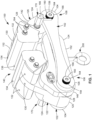
Figure 1 is a perspective view of an example of a beam anchor, illustrating a pair of arm assemblies located between a pair of braces, and further illustrating a torque arm and a slotted arm of each arm assembly; -
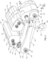
Figure 2 is a further perspective view of the beam anchor ofFigure 1 ; -
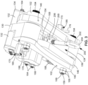
Figure 3 is a view of the underside of the beam anchor taken along line 3 ofFigure 2 illustrating a loading mechanism having a loading member (e.g., eye bolt) protruding out of a slotted arm gap between the slotted arms of the arm assemblies; -
Figure 4 is a cross-sectional view of the beam anchor taken along line 4-4 ofFigure 5 , and illustrating an example of a locking mechanism in a locked position for locking the torque arm to the slotted arm of one of the arm assemblies; -
Figure 5 is a cross-sectional view of the locking mechanism ofFigure 4 moved to an unlocked position allowing the torque arm to freely pivot relative to the slotted arm; -
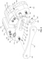
Figure 6 is a partially exploded view of the beam anchor ofFigures 1-5 in which one of the braces is separated away to illustrate one of the slotted arms; -
Figure 7 is an exploded view of the beam anchor; -
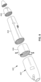
Figure 8 is an exploded view of an aircraft fuselage comprising a series of barrel sections; -
Figure 9 is a perspective view of one of the barrel sections ofFigure 8 , illustrating a network of floor beams for supporting a plurality of floorboards; -
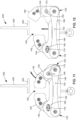
Figure 10 is a view of the underside of the floor beams taken alongline 10 ofFigure 9 ; -
Figure 11 is a front view of the beam anchor, and a cross-sectional view of a beam upon which the beam anchor is to be installed; -
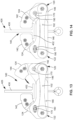
Figure 12 shows one of the torque arms of the beam anchor pivoted into an open position to provide a jaw gap allowing the installation of the beam anchor onto the beam; -
Figure 13 shows the beam anchor mounted on the beam after moving the beam anchor outwardly until the beam flange passes through the jaw gap; -
Figure 14 shows the torque arm pivoted into a closed position and locked in position to thereby secure the beam anchor onto the beam; -
Figure 15 is a bottom-up perspective view of the beam anchor mounted to the beam; -
Figure 16 is a top-down perspective view of the beam anchor mounted to the beam; -
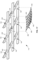
Figure 17 is a bottom-up perspective view of a floor beam network showing a plurality of the anchors mounted to the beams; -
Figure 18 shows a safety net secured to the beam anchors ofFigure 17 ; -
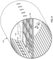
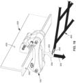
Figure 19 is a magnified view of the portion of the safety net installation identified byreference numeral 19 ofFigure 18 ; -
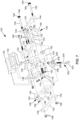
Figure 20 is a front view of the beam anchor installed on a beam, with one of the braces removed to illustrate a connector pin extending into each of the arm slots respectively formed in the slotted arms; -
Figure 21 illustrates the application of a tensile load to the connector pin, causing the slotted arms to pivot away from each other, and the jaw portions to clamp onto the web of the beam; -
Figure 22 is a flowchart of operations included in a method of installing a beam anchor on a beam. - Disclosed examples or versions will now be described more fully hereinafter with reference to the accompanying drawings, in which some, but not all of the disclosed examples or versions are shown. Indeed, several different examples or versions may be provided, and should not be construed as limited to the examples or versions set forth herein. Rather, these examples or versions are provided so that this disclosure will be thorough and fully convey the scope of the disclosure to those skilled in the art.
- This specification includes references to "some examples," "one example," or "an example." Instances of the phrases "some examples," "one example" or "an example" do not necessarily refer to the same example. Particular features, structures, or characteristics may be combined in any suitable manner consistent with this disclosure.
- As used herein, "comprising" is an open-ended term, and as used in the claims, this term does not foreclose additional structures or steps.
- As used herein, "configured to" means various parts or components may be described or claimed as "configured to" perform a task or tasks. In such contexts, "configured to" is used to connote structure by indicating that the parts or components include structure that performs those task or tasks during operation. As such, the parts or components can be said to be configured to perform the task even when the specified part or component is not currently operational (e.g., is not on).
- As used herein, an element or step recited in the singular and preceded by the word "a" or "an" should be understood as not necessarily excluding the plural of the elements or steps.
- As used herein, the phrase "at least one of," when used with a list of items, means different combinations of one or more of the listed items may be used, and only one of each item in the list may be needed. In other words, "at least one of' means any combination of items and number of items may be used from the list, but not all of the items in the list are required. The item may be a particular object, a thing, or a category.
- Referring to
Figures 1-7 , shown is an example of abeam anchor 100 configured to be removably coupled to a beam 426 (Figure 11 ) having a web 430 (Figure 11 ) and at least oneflange 432. Thebeam anchor 100 can be part of a fall protection system 110 (Figures 18-20 ) configured to provide protection from fall hazards, including safely arresting the fall of a person. In one example, a plurality of the beam anchors 100 can be coupled to an arrangement of beams 426 (Figure 9 ), and any one of a variety of different types of fall protection devices can be secured to the beam anchors 100, such as safety harnesses (not shown), orsafety nets 400 as shown inFigures 17-19 and described below. Advantageously, thebeam anchor 100 is capable of being installed on abeam 426 using only one hand. In addition, thebeam anchor 100 does not require the tightening or manipulating of levers, clamps, or other hardware in order to secure thebeam anchor 100 to abeam 426. - As mentioned above, the
beam anchor 100 can be installed on abeam 426 having avertical web 430 and at least onehorizontal flange 432. In the example ofFigures 9-16 described below, thebeam anchor 100 is removably installed on an I-beam. The I-beam has an I-shaped cross section having upper and lowerhorizontal flanges 432 interconnected by avertical web 430. Thevertical web 430 is centered on the upper and lowerhorizontal flanges 432. In another example, thebeam anchor 100 can be installed on abeam 426 having a T-shaped cross section having a single lowerhorizontal flange 432 and avertical web 430. Thebeam anchor 100 can be sized for mounting onbeams 426 of any size. For example, thebeam anchor 100 can be sized for mounting on abeam 426 having aflange 432 width of up to several inches or more, and/or on abeam 426 in which thevertical web 430 has a thickness of up to 1 inch or more. - As shown in
Figures 1-3 and6-7 , thebeam anchor 100 includes a pair ofbraces 102 arranged in spaced and parallel relation to each other. Eachbrace 102 has opposing brace ends 104. Thebeam anchor 100 additionally includes afirst arm assembly 120 and asecond arm assembly 122. Each of the first andsecond arm assemblies torque arm 124 and a slottedarm 146. Eachtorque arm 124 has ajaw portion 130 and a torquearm pivot end 126. Each slottedarm 146 has a slottedarm pivot end 148 and a slottedportion 152 containing anarm slot 154 extending in a lengthwise direction of the slottedportion 152. - The
torque arm 124 and the slottedarm 146 of the first andsecond arm assemblies braces 102. In addition, thetorque arm 124 and the slottedarm 146 of the first andsecond arm assemblies braces 102 respectively at a pair ofpivot joints 160 respectively on first andsecond sides 106, 108 (i.e., opposite sides) of thebeam anchor 100. More specifically, the torquearm pivot end 126 of thetorque arm 124 and the slottedarm pivot end 148 of the slottedarm 146 of thefirst arm assembly 120 are pivotally coupled to the brace ends 104 of the pair ofbraces 102 at the pivot joint 160 on thefirst side 106 of thebeam anchor 100. Similarly, the torquearm pivot end 126 of thetorque arm 124 and the slottedarm pivot end 148 of the slottedarm 146 of thesecond arm assembly 122 are pivotally coupled to the brace ends 104 at the pivot joint 160 on thesecond side 108 of thebeam anchor 100. - In the
example beam anchor 100 ofFigures 1-7 , the pivot joint 160 on each of the first andsecond sides beam anchor 100 includes apivot pin 158 coupling the slottedarm pivot end 148 and the torquearm pivot end 126 to the brace ends 104 at thepivot joint 160. In the example shown, eachpivot pin 158 is amechanical fastener 164 in the form of abolt 166 secured on its end by one or more nuts 168. However, the pivot pins 158 may be provided in any one of a variety of alternative configurations, and are not limited tobolts 166. Further in this regard, the slottedarm 146, thetorque arm 124, and thebrace 102 on each of the first andsecond sides beam anchor 100 can be pivotably coupled in any manner, and are not limited to being pivotably coupled by pivot pins 158. - The
torque arm 124 and the slottedarm 146 of each of the first andsecond arm assemblies Figure 7 . Alternatively, thetorque arm 124 and the slottedarm 146 of each of the first andsecond arm assemblies brace 102 and the slottedarm 146, and a spacer between thebrace 102 and thetorque arm 124. - As shown in
Figures 1-3 and6 , the first andsecond arm assemblies braces 102 in a manner such that thejaw portions 130 oppose each other, and define ajaw gap 140 between the opposingjaw portions 130. In addition, the first andsecond arm assemblies braces 102 such that the slottedportions 152 are in side-by-side and overlapping relation with each other, and are spaced apart to define a slottedarm gap 156, as shown inFigure 3 . - In the example of
Figures 1-7 , the first andsecond arm assemblies dedicated locking mechanism 170 for locking and unlocking thetorque arm 124 to the slottedarm 146 of the respective first andsecond arm assemblies locking mechanism 170 is movable between a locked position 190 (Figure 4 ) and an unlocked position 192 (Figure 5 ). When thelocking mechanism 170 of the first orsecond arm assembly 122 is in the lockedposition 190, therespective torque arm 124 is locked to the slottedarm 146, thereby preventing thetorque arm 124 from pivoting relative to the slottedarm 146. When thetorque arm 124 of the first orsecond arm assembly 122 is locked to the respective slottedarm 146, thetorque arm 124 is in aclosed position 142. Thebeam anchor 100 is sized and configured such that when thetorque arms 124 of both the first andsecond arm assemblies closed position 142, the jaw gap 140 (Figures 11 and14 ) between thejaw portions 130 is narrower than the width of theflange 432 of thebeam 426 on which thebeam anchor 100 is to be installed. Thelocking mechanism 170 is typically placed in the lockedposition 190 after thebeam anchor 100 has been installed on abeam 426, as shown inFigure 14 and described below. - When the
locking mechanism 170 of the first orsecond arm assembly 122 is in the unlocked position 192 (Figures 12-13 ), therespective torque arm 124 is freely pivotable relative to the slottedarm 146. In theunlocked position 192, therespective torque arm 124 can be pivoted into an open position 144 (e.g.,Figures 12-13 ) that provides ajaw gap 140 enabling the installation or removal of thebeam anchor 100 from thebeam 426, as shown inFigures 13-14 and described below. More specifically, thebeam anchor 100 is sized and configured such that when thetorque arm 124 of at least one of the first andsecond arm assemblies open position 144, thejaw gap 140 between the pair ofjaw portions 130 is at least as wide as theflange 432 of thebeam 426. - Referring to
Figures 4-5 , in one example of thebeam anchor 100, eachlocking mechanism 170 comprises alocking pin 172 that is axially movable within pin bores 128 in therespective torque arm 124 and slottedarm 146. Thelocking pin 172 is movable between the lockedposition 190 and theunlocked position 192. The pin bore 128 in eachtorque arm 124 is located between the torquearm pivot end 126 and thejaw portion 130. The pin bore 128 in each slottedarm 146 is located in apin tab 150 protruding from an upper side of the slottedarm 146 near the slottedarm pivot end 148. However, in other examples not shown, thepin tab 150 can be formed at any one of a variety of other locations on thetorque arm 124. Thelocking mechanism 170 of each first andsecond arm assembly locking pin 172 is in the lockedposition 190, the lockingpin 172 extends through the pin bores 128 of both thetorque arm 124 and the slottedarm 146 in a manner such that thetorque arm 124 is locked to the slottedarm 146. When thelocking pin 172 is in theunlocked position 192, the lockingpin 172 extends through only one of the pin bores 128 (e.g., the pin bore 128 of the torque arm 124), thereby allowing thetorque arm 124 to pivot relative to the slottedarm 146. - Referring to
Figures 4-5 , thelocking mechanism 170 has alocking pin 172 that is axially slidable within apin sleeve 182 in thetorque arm 124. Thepin sleeve 182 has a threadedportion 178 which is threadably installed in the pin bore 128 in thetorque arm 124. Thepin sleeve 182 also has ahex portion 180 located adjacent to the threadedportion 178 and which protrudes out of thetorque arm 124. Thehex portion 180 facilitates the installation (e.g., via a wrench) of the threadedportion 178 into thetorque arm 124. - The
locking mechanism 170 ofFigures 4-5 includes apin shaft 174 extending from the lockingpin 172. Although not shown, one end of thepin shaft 174 can be threaded, and thelocking pin 172 can be threadably engaged to the threaded end of thepin shaft 174. On an opposite end, thepin shaft 174 has apin handle 176 protruding laterally out of apin slot 186 formed in thehex portion 180, as shown inFigure 3 . The pin handle 176 is configured to move within thepin slot 186 when thepin handle 176 is manually grasped for moving thelocking pin 172 between the lockedposition 190 and theunlocked position 192. When thelocking pin 172 is moved to the lockedposition 190 as shown inFigure 4 , the free end of thelocking pin 172 is received within apin receptacle 188 affixed to the pin bore 128 in the slottedarm 146. When thelocking pin 172 is moved to theunlocked position 192 as shown inFigure 5 , the free end of thelocking pin 172 is retracted inside thepin sleeve 182 in thetorque arm 124. - In some examples, the locking
pin 172 can be biased (e.g., spring-loaded) toward the lockedposition 190. For example, as shown inFigures 4-5 , thelocking mechanism 170 can include acoil spring 184 captured inside thepin sleeve 182 and surrounding thepin shaft 174. When thelocking pin 172 is aligned with the pin bore 128 (e.g., the pin receptacle 188) in the slottedarm 146 and when the clocking of the pin handle 176 matches the clocking of thepin slot 186 in thehex portion 180, the lockingpin 172 is urged by thecoil spring 184 into the pin bore 128, thereby locking thetorque arm 124 to the slottedarm 146. Thelocking pin 172 can be temporarily fixed in theunlocked position 192 by pulling the pin handle 176 along thepin slot 186 until thepin handle 176 clears the end of thehex portion 180, and then rotating the pin handle 176 out of alignment with thepin slot 186 so that the pin handle 176 bears against the end surface of thehex portion 180. Thelocking pin 172 can be moved back toward the lockedposition 190 by rotating the pin handle 176 until aligned with thepin slot 186, after which thecoil spring 184 will urge thelocking pin 172 into the lockedposition 190 when thelocking pin 172 is aligned with the pin bore 128 in the slottedarm 146. - Although the present example of the
beam anchor 100 includes adedicated locking mechanism 170 for each of the first andsecond arm assemblies first arm assembly 120 includes alocking mechanism 170 that allows itstorque arm 124 to pivot into anopen position 144 allowing for installation and removal of thebeam anchor 100 on abeam 426. In such an alternative example, thesecond arm assembly 122 is devoid of alocking mechanism 170, and thetorque arm 124 and the slottedarm 146 of thesecond arm assembly 122 can be fixedly coupled to each other. - Referring to
Figures 1-3 and6-7 , thebeam anchor 100 includes aloading mechanism 200 for loading thebeam anchor 100 when mounted to abeam 426. Theloading mechanism 200 includes a connector pin 206 (Figures 5 and seven) that extends across the slottedarm gap 156 and into botharm slots 154 of the slottedarms 146, as shown inFigures 3 and6 . Theloading mechanism 200 includes aloading member 202 coupled to theconnector pin 206 and extending out of the slotted arm gap 156 (Figure 3 ). Theconnector pin 206 hasshoulders 208 on opposite sides of theloading member 202 to restrict axial motion of theconnector pin 206. Theconnector pin 206 is centered within thebeam anchor 100 to ensure that loads are centered on thebeam 426. - The
loading member 202 can be provide as a shaft-like member extending perpendicularly from theconnector pin 206, such as the eye bolt 204 (i.e., a closed-ring hook bolt) shown in the figures. In the example shown, theeye bolt 204 has a threadedportion 178 that extends through theconnector pin 206, and is secured via alock nut 168. However, in an alternative configuration, the loading member 202 (e.g., the eye bolt 204) and theconnector pin 206 can be a unitary structure (e.g., welded together). - As shown in
Figures 20-21 , thebeam anchor 100 is configured such that when mounted on abeam 426 with the lockingmechanisms 170 in the lockedposition 190, aload 300 on theconnector pin 206 causes the slottedarms 146 to pivot away from each other, and thetorque arms 124 to pivot toward each other. More specifically, theload 300 on theconnector pin 206 is the result of a tensile load (e.g., a downward load) on the loading member 202 (e.g., the eye bolt 204). Theconnector pin 206 transfers the tensile load to the slottedarms 146, causing theconnector pin 206 to urge the slottedarms 146 to pivot away from each other about the pivot pins 158 respectively on the first andsecond sides connector pin 206 slides along thearm slots 154. Simultaneously, thetorque arms 124 pivot toward each other, causing thejaw portions 130 to engage theweb 430 of thebeam 426. In this regard, thejaw portions 130 apply a clampingforce 302 to theweb 430 as shown inFigure 21 . The clampingforce 302 locks thebeam anchor 100 to thebeam 426, and prevents movement of thebeam anchor 100 relative to thebeam 426. - The
load 300 on theloading member 202 can be caused by the weight of equipment (e.g., tools, materials, etc.) or a person falling on a safety harness (not shown) or asafety net 400 that is attached to beam anchors 100 that are mounted to beams 426 (e.g.,Figures 17-18 ). For example, a plurality of beam anchors 100 can be mounted tofloor beams 428 of abarrel section 424 of an aircraft 420 (Figures 8-9 ) in preparation for the manual placement offloorboards 434 on the floor beams 428, as shown inFigures 8-16 and described below. Following the mounting of the beam anchors 100 to the floor beams 428,safety nets 400 can be attached to the beam anchors 100, as shown inFigure 17-19 and described below. Anexample safety net 400 can be comprised of elastic webbing arranged in a cross pattern. Thesafety net 400 can attached to the loading members 202 (e.g., eye bolts 204) of the beam anchors 100 using attachment clips 402, such as locking D-ring carabiners, or other attachment devices. - Referring to the example of
Figures 1-3 and6-7 , thebeam anchor 100 includes a pair of jaw blocks 132 on opposite sides of thejaw portion 130 of thetorque arm 124 of each of the first andsecond arm assemblies beam 426. For example, the jaw blocks 132 are configured to distribute forces on theweb 430 when thejaw portions 130 engage theweb 430, and apply a clamping force 302 (Figure 21 ) on theweb 430. In the example shown, the jaw blocks 132 are attached to opposite sides of thejaw portion 130 usingmechanical fasteners 164. In another example not shown, the jaw blocks 132 of eachtorque arm 124 can be integral with thejaw portion 130. - In
Figures 1-3 and6-7 , thebeam anchor 100 further includes ajaw pad 134 covering thejaw portion 130 and the jaw blocks 132 on each of the first andsecond arm assemblies jaw pad 134 has a web-bearing face 136 (Figure 20 ) and a flange-bearing face 138 (Figure 20 ) configured to respectively bear against a vertically orientedweb 430 and a horizontally orientedflange 432 of thebeam 426. Thejaw pads 134 can be mechanically coupled to the jaw blocks 132 andjaw portion 130 using the above-described mechanical fasteners 164 (Figure 20 ). Eachjaw pad 134 can be formed of a material that is softer than the material of thebeam 426 to which thebeam anchor 100 is to be mounted. Thejaw pads 134 are configured to protect thebeam 426 from scratching, indentations, dents, scrapes, and other types of damage. In one example, thejaw pads 134 can be formed of impact resistant polyurethane, although thejaw pads 134 can be formed of any one of a variety of materials. - The hardware of the
beam anchor 100 is preferably formed of metallic material, such as steel. For example, thelocking mechanism 170 including the locking pins 172, thepin sleeves 182, the pin handles 176, thepin receptacles 188, the pivot pins 158, and the loading mechanism 200 (e.g., theconnector pin 206 and the eye bolt 204) can be formed of metallic material. However, any one or more of the above-described hardware components can be formed of high-strength polymeric material. - Any one or more of the non-hardware components of the
beam anchor 100 are preferably formed of a non-metallic material, such as polymeric material. For example, thebraces 102, thetorque arms 124 and slottedarms 146 of the first andsecond arm assemblies jaw pads 134 can be formed of a thermoplastic material, such as carbon fiber polyether ether ketone (PEEK). The above-mentioned components can be formed using additive manufacturing (e.g., 3D printing), injection molding, or other suitable manufacturing techniques. Advantageously, carbon fiber PEEK has favorable mechanical properties at elevated temperatures including low mass (i.e., lightweight), excellent chemical resistance, a low coefficient of thermal expansion, and low moisture absorption. Although PEEK is a preferred material for forming the above-mentioned components, any suitable metallic and/or non-metallic material can be used. Advantageously, the first andsecond arm assemblies beam anchor 100 are identical in size, shape, and material, as are thebraces 102, which can reduce manufacturing costs. - Referring to
Figure 22 , shown is a flowchart of operations included in amethod 500 of installing abeam anchor 100 on abeam 426. Themethod 500 is described in the context of installing abeam anchor 100 on afloor beam 428 of abarrel section 424 of anaircraft 420fuselage 422, as shown inFigures 8-9 . As described above, thebeam 426 has aweb 430 and at least oneflange 432 oriented perpendicular to theweb 430, as shown inFigure 10 . - Step 502 of the
method 500 includes providing abeam anchor 100, an example of which is shown inFigures 1-9 and described above. As noted above, thebeam anchor 100 comprises a pair ofbraces 102, and first andsecond arm assemblies torque arm 124 having ajaw portion 130, and a slottedarm 146 having a slottedportion 152 containing anarm slot 154. The first andsecond arm assemblies braces 102 such that thejaw portions 130 oppose each other, the slottedportions 152 are side-by-side, and thetorque arm 124 and the slottedarm 146 of the first andsecond arm assemblies braces 102 respectively at a pair ofpivot joints 160 respectively on the first andsecond sides beam anchor 100. Thebeam anchor 100 also includes aconnector pin 206 which extends across the slottedarm gap 156 and into botharm slots 154, and a loading member 202 (e.g., eye bolt 204) is coupled to theconnector pin 206 for loading thebeam anchor 100 as described below. - Referring to
Figures 11-12 ,step 504 of themethod 500 includes pivoting thetorque arm 124 of thefirst arm assembly 120 into anopen position 144 that provides ajaw gap 140 between thejaw portions 130 that is at least as wide as theflange 432 of thebeam 426. Prior to pivoting thetorque arm 124, thelocking mechanism 170 of thefirst arm assembly 120 is moved to the unlocked position 192 (e.g.,Figure 5 ) to allow thetorque arm 124 to pivot. In the above-described example ofFigures 4-5 in which thelocking mechanism 170 includes acoil spring 184, the method includes placing thelocking mechanism 170 in theunlocked position 192 by manually pulling the pin handle 176 along thepin slot 186 until thepin handle 176 clears the end of thehex portion 180, and then rotating the pin handle 176 out of alignment with thepin slot 186 so that thepin handle 176 is held against the end surface of thehex portion 180 under the biasing force of thecoil spring 184. As shown inFigures 11-12 , thelocking mechanism 170 of thesecond arm assembly 122 is already in the locked position 190 (e.g.,Figure 4 ), thereby maintaining thetorque arm 124 of thesecond arm assembly 122 in theclosed position 142. - Step 506 of the
method 500 includes mounting thebeam anchor 100 on thebeam 426. In the context ofFigures 12-13 ,step 506 comprises mounting thebeam anchor 100 to one of the floor beams 428 of thebarrel section 424. Beam anchors can be mounted to anaircraft 420 at any time, including when theaircraft 420 is under construction, or when theaircraft 420 is undergoing maintenance, refurbishment, or repair. Step 506 of the mounting thebeam anchor 100 includes moving thebeam anchor 100 upwardly (e.g., with one hand) until theflange 432 passes through thejaw gap 140 as shown inFigure 12 , followed by moving thebeam anchor 100 laterally (e.g., in a sideways direction), and resting thejaw portion 130 of thesecond arm assembly 122 on theflange 432, as shown inFigure 13 . - Step 508 of the
method 500 includes pivoting thetorque arm 124 of thefirst arm assembly 120 from the open position 144 (Figure 13 ) to theclosed position 142 as shown inFigure 14 . With the weight of thebeam anchor 100 supported by thejaw portion 130 of thesecond arm assembly 122 resting on theflange 432 of thebeam 426, thetorque arm 124 on thefirst arm assembly 120 can be manually pivoted into theclosed position 142 using one hand. - After pivoting the
torque arm 124 of thefirst arm assembly 120 into theclosed position 142, step 510 of themethod 500 includes locking thetorque arm 124 of thefirst arm assembly 120 in theclosed position 142, which can also be performed using one hand. For the above-described example in which thelocking mechanism 170 of thefirst arm assembly 120 comprises thelocking pin 172,step 510 comprises axially sliding thelocking pin 172 of thetorque arm 124 into the pin bore 128 (e.g., the pin receptacle 188) in the slottedarm 146, thereby moving thelocking pin 172 from the unlocked position 192 (Figure 5 ) to the locked position 190 (Figure 4 ), and locking thetorque arm 124 in theclosed position 142. For some examples of thelocking mechanism 170, the method includes biasing thelocking pin 172 toward the lockedposition 190, such that when thelocking pin 172 is aligned with the pin bore 128 in the slottedarm 146, the lockingpin 172 is automatically urged into the pin bore 128. In the above-described example, thelocking mechanism 170 includes the coil spring 184 (Figures 4-5 ), and thelocking pin 172 can be moved to the lockedposition 190 by rotating the pin handle 176 until aligned with thepin slot 186, after which thecoil spring 184 urges thelocking pin 172 into the pin bore 128 when aligned with thelocking pin 172.Figures 15-16 show thebeam anchor 100 mounted to thebeam 426, with both lockingmechanisms 170 in the lockedposition 190. - The
method 500 further includes applying aload 300 to theconnector pin 206 in a manner causing the slottedarms 146 to pivot away from each other as theconnector pin 206 slides along thearm slots 154, and thetorque arms 124 pivot toward each other until thejaw portions 130 engage theweb 430 of thebeam 426, as shown inFigures 20-21 . InFigures 17-19 , the step of applying aload 300 to theconnector pin 206 can result from aload 300 applied to theloading member 202 of theloading mechanism 200. In the example shown, the step of applying theload 300 to theconnector pin 206 comprises applying a tensile load to aloading member 202, which is coupled to theconnector pin 206 as shown inFigure 3 and described above. In the example shown, theloading member 202 is aneye bolt 204 that extends out of the slottedarm gap 156 between the slottedarms 146 as shown inFigure 19 . The step of applying the tensile load to theloading member 202 comprises attaching asafety net 400 or a safety tether (not shown) to theloading member 202, and subjecting the safety net or safety tether to a load 300 (e.g., due to a falling object or person). - The
method 500 further includes distributing, via a pair of jaw blocks 132 on opposite sides of thejaw portions 130 of the first andsecond arm assemblies web 430 when clamping theweb 430 between thejaw portions 130 of the first andsecond arm assemblies Figure 21 , thejaw portions 130 apply a clampingforce 302 on theweb 430 when a load 300 (e.g., a downward load) is applied to theconnector pin 206 via the loading member 202 (e.g., the eye bolt 204). The jaw blocks 132 distribute the clampingforce 302 on theweb 430 and thereby prevent potential damage that may otherwise occur due to concentrated clamping forces applied by thejaw portions 130 alone. - Further in this regard, the
method 500 includes protecting thebeam 426 withjaw pads 134 covering the jaw blocks 132 andjaw portions 130 of the first andsecond arm assemblies jaw portions 130 when engaging thebeam 426 and apply clampingforce 302 to theweb 430. As described above, the first andsecond arm assemblies jaw pad 134 covering thejaw portion 130 and jaw blocks 132, and which can be formed of a material that is softer than thebeam 426, to thereby prevent damage to thebeam 426. - The
method 500 can further include removing thebeam anchor 100 from thebeam 426 by unlocking thetorque arm 124 of the first arm assembly 120 (e.g., using one hand), and pivoting the torque arm 124 (e.g., using one hand) into theopen position 144. With thetorque arm 124 in theopen position 144, the method includes removing thebeam anchor 100 from thebeam 426 by moving thebeam anchor 100 downwardly (e.g., using one hand) until theflange 432 of thebeam 426 passes through thejaw gap 140 between the opposingjaw portions 130 of thebeam anchor 100. The process of removing thebeam anchor 100 from thebeam 426 is a reversal of the above-described process of installing thebeam anchor 100. - Many modifications and other configurations of the disclosure will come to mind to one skilled in the art, to which this disclosure pertains, having the benefit of the teachings presented in the foregoing descriptions and the associated drawings. The configurations described herein are meant to be illustrative and are not intended to be limiting or exhaustive. Although specific terms are employed herein, they are used in a generic and descriptive sense only and not for purposes of limitation.
Claims (15)
- A beam anchor (100) for mounting on a beam (426) having a web (430) and a flange (432) oriented perpendicular to the web (430), the beam anchor (100) comprising:a pair of braces (102) positionable in parallel relation to each other;a first arm assembly (120) and a second arm assembly (122), each comprising a torque arm (124) having a jaw portion (130), and a slotted arm (146) having a slotted portion (152) containing an arm slot (154), and the first and second arm assemblies (120, 122) are positionable between the braces (102) such that:the jaw portions (130) oppose each other;the slotted portions (152) are side-by-side;the torque arm (124) and the slotted arm (146) of the first and second arm assemblies (120, 122) are coupled to the braces (102) respectively at a pair of pivot joints (160) on opposite sides of the beam anchor (100);a locking mechanism (170), movable between a locked position (190) in which the torque arm (124) of one of the first or second arm assemblies (120, 122) is locked to the slotted arm (146) of the same one of the first or second arm assemblies (120, 122), and an unlocked position (192) in which the torque arm (124) is freely pivotable relative to the slotted arm (146);a connector pin (206) configured to extend into both of the arm slots (154); andwherein the beam anchor (100) is configured such that when mounted on the beam (426) and with the locking mechanism (170) in the locked position (190), a load (300) applied to the connector pin (206) causes the slotted arms (146) to pivot away from each other as the connector pin (206) slides along the arm slots (154), and the torque arms (124) pivot toward each other until the jaw portions (130) engage the web (430) of the beam (426).
- The beam anchor (100) of any preceding Claim, wherein:the slotted portions (152) are spaced apart to define a slotted arm gap (156);the connector pin (206) is coupled to a loading member (202) extending out of the slotted arm gap (156); andthe load (300) on the connector pin (206) results from a tensile load (300) on the loading member (202).
- The beam anchor (100) of any preceding Claim, wherein:
the locking mechanism (170) comprises a locking pin (172) insertable into a pin bore (128) in one of the torque arm (124) or the slotted arm (146), and the locking pin (172) is axially movable between the locked position (190) and the unlocked position (192); and optionally wherein:
the locking pin (172) is biased toward the locked position (190), such that when the locking pin (172) is aligned with the pin bore (128), the locking pin (172) is urged into the pin bore (128), thereby locking the torque arm (124) to the slotted arm (146). - The beam anchor (100) of any preceding Claim, wherein:
the first and second arm assemblies (120, 122) each have a dedicated locking mechanism (170) for locking and unlocking pivoting motion of the respective torque arm (124) relative to the respective slotted arm (146). - The beam anchor (100) of any preceding Claim, wherein:
each torque arm (124) has a pair of jaw blocks (132) on opposite sides of the jaw portion (130), for distributing forces applied to the web (430) of the beam (426). - The beam anchor (100) of Claim 5, wherein:
the first and second arm assemblies (120, 122) each include a jaw pad (134) covering the jaw portion (130) and extending across the jaw blocks (132); and optionally wherein:
each jaw pad (134) has a web-bearing face (136) and a flange-bearing face (138) configured to respectively bear against the web (430) and the flange (432) of the beam (426). - The beam anchor (100) of any preceding Claim, wherein:
the first and second arm assemblies (120, 122) are identical in size and shape. - A fall protection system (110), comprising:
one or more beam anchors (100) of any preceding claim, each configured for clamping onto a beam (426) having a web (430) and a flange (432) perpendicular to the web (430), each beam anchor (100) comprising:a pair of braces (102), positionable in parallel relation to each other;a pair of arm assemblies, each comprising a torque arm (124) having a jaw portion (130), and a slotted arm (146) having a slotted portion (152) containing an arm slot (154), and positionable between the braces (102) such that:the jaw portions (130) oppose each other;the slotted portions (152) are side-by-side;the torque arm (124) and the slotted arm (146) of the pair of arm assemblies are coupled to the braces (102) respectively at a pair of pivot joints (160) on opposite sides of the beam anchor (100);at least one locking mechanism (170), movable between a locked position (190) in which the torque arm (124) of one of the arm assemblies is non-pivotably locked to the slotted arm (146) of the same one of the arm assemblies, and an unlocked position (192) in which the torque arm (124) is freely pivotable;a connector pin (206), configured to extend into both of the arm slots (154);a safety net (400) attached to the one or more beam anchors (100); andwherein each beam anchor (100) is configured such that when mounted on a beam (426) and with the locking mechanism (170) in the locked position (190), a load (300) on the safety net (400) is transferred to the connector pin (206), causing the slotted arms (146) to pivot away from each other as the connector pin (206) slides along the arm slots (154), and causing the torque arms (124) to pivot toward each other until the jaw portions (130) engage the web (430) of the beam (426). - A method (500) of installing a beam anchor (100) on a beam (426) having a web (430) and a flange (432) perpendicular to the web (430), comprising:providing a beam anchor (100), comprising:a pair of braces (102) parallel to each other;a first arm assembly (120) and a second arm assembly (122), each comprising a torque arm (124) having a jaw portion (130), and a slotted arm (146) having a slotted portion (152) containing an arm slot (154), the first and second arm assemblies (120, 122) are positioned between the braces (102) such that:the jaw portions (130) oppose each other;the slotted portions (152) are side-by-side;the torque arm (124) and the slotted arm (146) of the first and second arm assemblies (120, 122) are coupled to the braces (102) respectively at a pair of pivot joints (160) on opposite sides of the beam anchor (100);a connector pin (206) extending into both of the arm slots (154);pivoting the torque arm (124) of the first arm assembly (120) into an open position (144) that provides a jaw gap (140) between the jaw portions (130) that is at least as wide as the flange (432) of the beam (426);mounting the beam anchor (100) on the beam (426) by moving the beam anchor (100) such that the flange (432) passes through the jaw gap (140), and resting the jaw portion (130) of the second arm assembly (122) on the flange (432);pivoting the torque arm (124) of the first arm assembly (120) into a closed position (142) that provides a jaw gap (140) that is narrower that the flange (432) of the beam (426); andlocking the torque arm (124) of the first arm assembly (120) in the closed position (142).
- The method (500) of Claim 9, further comprising:
applying a load (300) to the connector pin (206) in a manner causing the slotted arms (146) to pivot away from each other as the connector pin (206) slides along the arm slots (154), and the torque arms (124) pivot toward each other until the jaw portions (130) engage the web (430) of the beam (426). - The method (500) of Claim 10, wherein applying a load (300) to the connector pin (206) comprises:
applying a tensile load (300) to a loading member (202) coupled to the connector pin (206) and extending out of a slotted arm gap (156) between the slotted arms (146). - The method (500) of Claim 11, wherein applying a tensile load (300) to the loading member (202) comprises:
applying the load (300) to a safety net (400) or a safety tether attached to the loading member (202). - The method (500) of any of Claims 10 to 12, further comprising:
distributing, via a pair of jaw blocks (132) on opposite sides of the jaw portions (130) of each of the first and second arm assemblies (120, 122), clamping forces on the web (430) when the jaw portions (130) engage the web (430) as a result of the load (300) on the connector pin (206); and optionally
protecting the beam (426) with jaw pads (134) covering the jaw blocks (132) and jaw portions (130) respectively of the first and second arm assemblies (120, 122). - The method (500) of Claim 9, wherein locking the torque arm (124) in the closed position (142) comprises:
axially sliding a locking pin (172) of one of the torque arm (124) or the slotted arm (146) of the first arm assembly (120), into a pin bore (128) formed in a remaining one of the torque arm (124) or the slotted arm (146) of the first arm assembly (120); and optionally further comprising:
biasing the locking pin (172) toward the locked position (190), such that when the locking pin (172) is aligned with the pin bore (128), the locking pin (172) is urged into the pin bore (128). - The method (500) of Claim 9, further comprising removing the beam anchor (100) by performing the following:unlocking the torque arm (124) of the first arm assembly (120);pivoting the torque arm (124) of the first arm assembly (120) into the open position (144); and
removing the beam anchor (100) from the beam (426) by moving the beam anchor (100) such that the flange (432) of the beam (426) passes through the jaw gap (140); and/or wherein mounting the beam anchor (100) on the beam (426) comprises:mounting the beam anchor (100) on a floor beam (428).
Applications Claiming Priority (1)
| Application Number | Priority Date | Filing Date | Title |
|---|---|---|---|
| US18/167,850 US12422091B2 (en) | 2023-02-11 | 2023-02-11 | Beam anchor and method of use |
Publications (2)
| Publication Number | Publication Date |
|---|---|
| EP4417269A1 true EP4417269A1 (en) | 2024-08-21 |
| EP4417269B1 EP4417269B1 (en) | 2025-10-22 |
Family
ID=89772179
Family Applications (1)
| Application Number | Title | Priority Date | Filing Date |
|---|---|---|---|
| EP24154823.9A Active EP4417269B1 (en) | 2023-02-11 | 2024-01-30 | Beam anchor and method of use |
Country Status (5)
| Country | Link |
|---|---|
| US (1) | US12422091B2 (en) |
| EP (1) | EP4417269B1 (en) |
| JP (1) | JP2024125267A (en) |
| CN (1) | CN118477267A (en) |
| AU (1) | AU2023282279A1 (en) |
Families Citing this family (1)
| Publication number | Priority date | Publication date | Assignee | Title |
|---|---|---|---|---|
| US20250345640A1 (en) * | 2024-05-09 | 2025-11-13 | RIG Fall Protection, LLC | Portable industrial anchor system |
Citations (4)
| Publication number | Priority date | Publication date | Assignee | Title |
|---|---|---|---|---|
| US415689A (en) * | 1889-11-19 | williams | ||
| US2765139A (en) * | 1953-12-29 | 1956-10-02 | White Claude | Beam clamp |
| DE1096288B (en) * | 1958-09-11 | 1960-12-29 | Demag Zug Gmbh | Clamp for attaching the hanging rods of hanging railways to the lower chord of I-beams |
| DE4334635A1 (en) * | 1993-10-06 | 1995-04-13 | Ver Energiewerke Ag | Rope fixture for fastening a carrying rope |
Family Cites Families (5)
| Publication number | Priority date | Publication date | Assignee | Title |
|---|---|---|---|---|
| US4062519A (en) * | 1976-10-21 | 1977-12-13 | Plastic Products, Inc. | Pulley lift assembly and curtain system employing same |
| US4371203A (en) * | 1981-07-13 | 1983-02-01 | Munro Donald C | Universal beam clamp |
| US6962234B1 (en) * | 2002-07-13 | 2005-11-08 | Reeves Eric W | Sliding anchorage device |
| US10060146B2 (en) * | 2014-04-07 | 2018-08-28 | Conxtech, Inc. | I-beam-attachable lifeline system |
| US20220249888A1 (en) | 2021-02-11 | 2022-08-11 | The Boeing Company | Multiple Self-Retracting Lanyard, Single Brake Fall Protection Systems and Methods |
-
2023
- 2023-02-11 US US18/167,850 patent/US12422091B2/en active Active
- 2023-12-14 AU AU2023282279A patent/AU2023282279A1/en active Pending
- 2023-12-27 CN CN202311823394.6A patent/CN118477267A/en active Pending
-
2024
- 2024-01-30 EP EP24154823.9A patent/EP4417269B1/en active Active
- 2024-02-08 JP JP2024017590A patent/JP2024125267A/en active Pending
Patent Citations (4)
| Publication number | Priority date | Publication date | Assignee | Title |
|---|---|---|---|---|
| US415689A (en) * | 1889-11-19 | williams | ||
| US2765139A (en) * | 1953-12-29 | 1956-10-02 | White Claude | Beam clamp |
| DE1096288B (en) * | 1958-09-11 | 1960-12-29 | Demag Zug Gmbh | Clamp for attaching the hanging rods of hanging railways to the lower chord of I-beams |
| DE4334635A1 (en) * | 1993-10-06 | 1995-04-13 | Ver Energiewerke Ag | Rope fixture for fastening a carrying rope |
Also Published As
| Publication number | Publication date |
|---|---|
| JP2024125267A (en) | 2024-09-18 |
| CN118477267A (en) | 2024-08-13 |
| US20240271747A1 (en) | 2024-08-15 |
| AU2023282279A1 (en) | 2024-08-29 |
| EP4417269B1 (en) | 2025-10-22 |
| US12422091B2 (en) | 2025-09-23 |
Similar Documents
| Publication | Publication Date | Title |
|---|---|---|
| US5934626A (en) | Adjustable pipe roll and support mechanism | |
| US20240359043A1 (en) | Fall arrest system | |
| DE102009018487B4 (en) | Method and device for securing cargo in an aircraft | |
| US10322475B2 (en) | Adjustable pipe roll and support mechanism | |
| EP4417269B1 (en) | Beam anchor and method of use | |
| US7785053B2 (en) | Single tough locking seat fittings and methods | |
| US5259477A (en) | Collapsible scaffold bracket | |
| US6425458B1 (en) | Falling safeguard device | |
| US12146368B2 (en) | Parapet descent apparatus | |
| US9022376B2 (en) | Reconfigurable clamping system | |
| DK2812514T3 (en) | Suspension connection system configured for use with suspended scaffolding and associated methods | |
| US20040195479A1 (en) | Top & bottom mount, heavy load supporting, girder clamp system | |
| US20050189171A1 (en) | Safety system and method of use for high workers | |
| CA2514752A1 (en) | Stanchion for a horizontal lifeline system | |
| DE102016106533A1 (en) | backup column | |
| JP4058383B2 (en) | Scaffolding / curing unit and method of use | |
| US9162271B2 (en) | Deck leverage anchor with spaced-apart body portions | |
| KR102639574B1 (en) | safety system | |
| BR102023025872A2 (en) | BEAM ANCHOR FOR MOUNTING ON A BEAM, FALL PROTECTION SYSTEM, AND, METHOD FOR INSTALLING A BEAM ANCHOR ON A BEAM | |
| US11850721B2 (en) | System and method to install and remove an anchoring member on an anchorage structure in an overhead area | |
| AU2010100802A4 (en) | A lock | |
| CA2601849C (en) | System, apparatus and method for decoupling a railcar restraint | |
| WO2021089998A1 (en) | Anchor device | |
| JP7141419B2 (en) | Device for stretching main rope for container and method for stretching main rope for container | |
| US10099074B2 (en) | Fall protection device and systems and methods for use thereof |
Legal Events
| Date | Code | Title | Description |
|---|---|---|---|
| PUAI | Public reference made under article 153(3) epc to a published international application that has entered the european phase |
Free format text: ORIGINAL CODE: 0009012 |
|
| STAA | Information on the status of an ep patent application or granted ep patent |
Free format text: STATUS: THE APPLICATION HAS BEEN PUBLISHED |
|
| AK | Designated contracting states |
Kind code of ref document: A1 Designated state(s): AL AT BE BG CH CY CZ DE DK EE ES FI FR GB GR HR HU IE IS IT LI LT LU LV MC ME MK MT NL NO PL PT RO RS SE SI SK SM TR |
|
| STAA | Information on the status of an ep patent application or granted ep patent |
Free format text: STATUS: REQUEST FOR EXAMINATION WAS MADE |
|
| 17P | Request for examination filed |
Effective date: 20250214 |
|
| GRAP | Despatch of communication of intention to grant a patent |
Free format text: ORIGINAL CODE: EPIDOSNIGR1 |
|
| STAA | Information on the status of an ep patent application or granted ep patent |
Free format text: STATUS: GRANT OF PATENT IS INTENDED |
|
| INTG | Intention to grant announced |
Effective date: 20250704 |
|
| GRAS | Grant fee paid |
Free format text: ORIGINAL CODE: EPIDOSNIGR3 |
|
| GRAA | (expected) grant |
Free format text: ORIGINAL CODE: 0009210 |
|
| STAA | Information on the status of an ep patent application or granted ep patent |
Free format text: STATUS: THE PATENT HAS BEEN GRANTED |
|
| AK | Designated contracting states |
Kind code of ref document: B1 Designated state(s): AL AT BE BG CH CY CZ DE DK EE ES FI FR GB GR HR HU IE IS IT LI LT LU LV MC ME MK MT NL NO PL PT RO RS SE SI SK SM TR |
|
| REG | Reference to a national code |
Ref country code: CH Ref legal event code: F10 Free format text: ST27 STATUS EVENT CODE: U-0-0-F10-F00 (AS PROVIDED BY THE NATIONAL OFFICE) Effective date: 20251022 Ref country code: GB Ref legal event code: FG4D |
|
| REG | Reference to a national code |
Ref country code: DE Ref legal event code: R096 Ref document number: 602024000972 Country of ref document: DE |
|
| REG | Reference to a national code |
Ref country code: IE Ref legal event code: FG4D |
|
| P01 | Opt-out of the competence of the unified patent court (upc) registered |
Free format text: CASE NUMBER: UPC_APP_0010321_4417269/2025 Effective date: 20251020 |
|
| REG | Reference to a national code |
Ref country code: NL Ref legal event code: MP Effective date: 20251022 |
|
| PG25 | Lapsed in a contracting state [announced via postgrant information from national office to epo] |
Ref country code: NL Free format text: LAPSE BECAUSE OF FAILURE TO SUBMIT A TRANSLATION OF THE DESCRIPTION OR TO PAY THE FEE WITHIN THE PRESCRIBED TIME-LIMIT Effective date: 20251022 |
|
| PG25 | Lapsed in a contracting state [announced via postgrant information from national office to epo] |
Ref country code: ES Free format text: LAPSE BECAUSE OF FAILURE TO SUBMIT A TRANSLATION OF THE DESCRIPTION OR TO PAY THE FEE WITHIN THE PRESCRIBED TIME-LIMIT Effective date: 20251022 |
|
| REG | Reference to a national code |
Ref country code: LT Ref legal event code: MG9D |
|
| PG25 | Lapsed in a contracting state [announced via postgrant information from national office to epo] |
Ref country code: NO Free format text: LAPSE BECAUSE OF FAILURE TO SUBMIT A TRANSLATION OF THE DESCRIPTION OR TO PAY THE FEE WITHIN THE PRESCRIBED TIME-LIMIT Effective date: 20260122 |
|
| PGFP | Annual fee paid to national office [announced via postgrant information from national office to epo] |
Ref country code: DE Payment date: 20260128 Year of fee payment: 3 |
|
| PG25 | Lapsed in a contracting state [announced via postgrant information from national office to epo] |
Ref country code: AT Free format text: LAPSE BECAUSE OF FAILURE TO SUBMIT A TRANSLATION OF THE DESCRIPTION OR TO PAY THE FEE WITHIN THE PRESCRIBED TIME-LIMIT Effective date: 20251022 Ref country code: FI Free format text: LAPSE BECAUSE OF FAILURE TO SUBMIT A TRANSLATION OF THE DESCRIPTION OR TO PAY THE FEE WITHIN THE PRESCRIBED TIME-LIMIT Effective date: 20251022 Ref country code: HR Free format text: LAPSE BECAUSE OF FAILURE TO SUBMIT A TRANSLATION OF THE DESCRIPTION OR TO PAY THE FEE WITHIN THE PRESCRIBED TIME-LIMIT Effective date: 20251022 |
|
| PGFP | Annual fee paid to national office [announced via postgrant information from national office to epo] |
Ref country code: AT Payment date: 20260301 Year of fee payment: 3 |
|
| REG | Reference to a national code |
Ref country code: AT Ref legal event code: MK05 Ref document number: 1848670 Country of ref document: AT Kind code of ref document: T Effective date: 20251022 |
|
| PG25 | Lapsed in a contracting state [announced via postgrant information from national office to epo] |
Ref country code: RS Free format text: LAPSE BECAUSE OF FAILURE TO SUBMIT A TRANSLATION OF THE DESCRIPTION OR TO PAY THE FEE WITHIN THE PRESCRIBED TIME-LIMIT Effective date: 20260122 |
|
| PG25 | Lapsed in a contracting state [announced via postgrant information from national office to epo] |
Ref country code: IS Free format text: LAPSE BECAUSE OF FAILURE TO SUBMIT A TRANSLATION OF THE DESCRIPTION OR TO PAY THE FEE WITHIN THE PRESCRIBED TIME-LIMIT Effective date: 20260222 |
|
| PGFP | Annual fee paid to national office [announced via postgrant information from national office to epo] |
Ref country code: FR Payment date: 20260126 Year of fee payment: 3 |
|
| PG25 | Lapsed in a contracting state [announced via postgrant information from national office to epo] |
Ref country code: PT Free format text: LAPSE BECAUSE OF FAILURE TO SUBMIT A TRANSLATION OF THE DESCRIPTION OR TO PAY THE FEE WITHIN THE PRESCRIBED TIME-LIMIT Effective date: 20260223 |
|
| PG25 | Lapsed in a contracting state [announced via postgrant information from national office to epo] |
Ref country code: PL Free format text: LAPSE BECAUSE OF FAILURE TO SUBMIT A TRANSLATION OF THE DESCRIPTION OR TO PAY THE FEE WITHIN THE PRESCRIBED TIME-LIMIT Effective date: 20251022 |
|
| PG25 | Lapsed in a contracting state [announced via postgrant information from national office to epo] |
Ref country code: LV Free format text: LAPSE BECAUSE OF FAILURE TO SUBMIT A TRANSLATION OF THE DESCRIPTION OR TO PAY THE FEE WITHIN THE PRESCRIBED TIME-LIMIT Effective date: 20251022 |
|
| PG25 | Lapsed in a contracting state [announced via postgrant information from national office to epo] |
Ref country code: BG Free format text: LAPSE BECAUSE OF FAILURE TO SUBMIT A TRANSLATION OF THE DESCRIPTION OR TO PAY THE FEE WITHIN THE PRESCRIBED TIME-LIMIT Effective date: 20251022 |