EP4417165A2 - Iris-style crimpers for medical devices - Google Patents
Iris-style crimpers for medical devices Download PDFInfo
- Publication number
- EP4417165A2 EP4417165A2 EP24186296.0A EP24186296A EP4417165A2 EP 4417165 A2 EP4417165 A2 EP 4417165A2 EP 24186296 A EP24186296 A EP 24186296A EP 4417165 A2 EP4417165 A2 EP 4417165A2
- Authority
- EP
- European Patent Office
- Prior art keywords
- crimper
- medical device
- longitudinal portion
- elements
- implantable medical
- Prior art date
- Legal status (The legal status is an assumption and is not a legal conclusion. Google has not performed a legal analysis and makes no representation as to the accuracy of the status listed.)
- Pending
Links
Images





































Classifications
-
- A—HUMAN NECESSITIES
- A61—MEDICAL OR VETERINARY SCIENCE; HYGIENE
- A61F—FILTERS IMPLANTABLE INTO BLOOD VESSELS; PROSTHESES; DEVICES PROVIDING PATENCY TO, OR PREVENTING COLLAPSING OF, TUBULAR STRUCTURES OF THE BODY, e.g. STENTS; ORTHOPAEDIC, NURSING OR CONTRACEPTIVE DEVICES; FOMENTATION; TREATMENT OR PROTECTION OF EYES OR EARS; BANDAGES, DRESSINGS OR ABSORBENT PADS; FIRST-AID KITS
- A61F2/00—Filters implantable into blood vessels; Prostheses, i.e. artificial substitutes or replacements for parts of the body; Appliances for connecting them with the body; Devices providing patency to, or preventing collapsing of, tubular structures of the body, e.g. stents
- A61F2/95—Instruments specially adapted for placement or removal of stents or stent-grafts
- A61F2/9522—Means for mounting a stent or stent-graft onto or into a placement instrument
- A61F2/9524—Iris-type crimpers
-
- A—HUMAN NECESSITIES
- A61—MEDICAL OR VETERINARY SCIENCE; HYGIENE
- A61F—FILTERS IMPLANTABLE INTO BLOOD VESSELS; PROSTHESES; DEVICES PROVIDING PATENCY TO, OR PREVENTING COLLAPSING OF, TUBULAR STRUCTURES OF THE BODY, e.g. STENTS; ORTHOPAEDIC, NURSING OR CONTRACEPTIVE DEVICES; FOMENTATION; TREATMENT OR PROTECTION OF EYES OR EARS; BANDAGES, DRESSINGS OR ABSORBENT PADS; FIRST-AID KITS
- A61F2/00—Filters implantable into blood vessels; Prostheses, i.e. artificial substitutes or replacements for parts of the body; Appliances for connecting them with the body; Devices providing patency to, or preventing collapsing of, tubular structures of the body, e.g. stents
- A61F2/02—Prostheses implantable into the body
- A61F2/24—Heart valves ; Vascular valves, e.g. venous valves; Heart implants, e.g. passive devices for improving the function of the native valve or the heart muscle; Transmyocardial revascularisation [TMR] devices; Valves implantable in the body
- A61F2/2412—Heart valves ; Vascular valves, e.g. venous valves; Heart implants, e.g. passive devices for improving the function of the native valve or the heart muscle; Transmyocardial revascularisation [TMR] devices; Valves implantable in the body with soft flexible valve members, e.g. tissue valves shaped like natural valves
- A61F2/2418—Scaffolds therefor, e.g. support stents
Definitions
- the present application is generally related to devices for crimping stents, prosthetic heart valves and other implantable vascular medical devices.
- expandable implantable medical devices that include a stent structure and organic tissue, e.g ., bovine and porcine, such as prosthetic valves and other cardiac intervention devices, require onsite crimping onto a delivery device at the implantation site, e.g. , a catheterization laboratory ("cath lab"). This is due to the need to store the implantable devices in conditions specific to preserve the organic tissue.
- a catheterization laboratory e.g., a catheterization laboratory
- iris-style crimpers are utilized in the crimping processes.
- Current iris-style crimpers experience limitations due to side loading that leads to the difficulty in accurately placing medical devices relative to the delivery device inside of side loading crimpers.
- the techniques of this disclosure generally relate to crimpers for loading an implantable medical device onto a delivery device and converting the implantable medical device from an expanded state to a compressed state.
- the present disclosure provides a clamshell crimper for altering an expandable medical device from an uncompressed state to a compressed state.
- the crimper includes a top shell comprising a first plurality of crimper elements, the first plurality of crimper elements defining a top channel and a base shell comprising a second plurality of crimper elements, the second plurality of crimper elements defining a bottom channel.
- the top shell and the base shell are coupled at a pivot connection.
- the top shell is configured to rotate about the pivot connection relative to the base shell from an open state to a closed state.
- the crimper When in the open state, the second channel is exposed for loading the expandable medical device, and when in the closed state, the top channel and the bottom channel define a crimper chamber.
- the crimper also includes a handle configured to operate the clamshell crimper, one or more cams coupled to the handle, and one or more rods coupled to the one or more cams, the first plurality of crimper elements, and the second plurality of crimper elements.
- movement of the handle rotates the one or more cams thereby displacing the first plurality of crimper elements and the second plurality of crimper elements via the rods.
- the displacement of the first plurality of crimper elements and the second plurality of crimper elements decreases a volume of the crimper chamber to transition the expandable medical device from the uncompressed state to the compressed state.
- the disclosure provides that the top shell or the base shell comprises a first housing and a second housing.
- Each of the first plurality of crimper elements is movably coupled within the first housing and the second housing.
- one of the first housing or the second housing includes a side plate comprising an interior surface and an exterior surface.
- One or more crimper channels are formed within the interior surface of the side plate, and the one or more crimper channels are configured to allow the displacement of the first plurality of crimper elements or the second plurality of crimper elements.
- a crimper element from the first plurality of crimper elements or the second plurality of crimper elements includes a crimper lobe, wherein a portion of the crimper lobe forms a portion of the crimper chamber, and a first leg and a second leg coupled to the crimper lobe.
- a rod from the one or more rods is coupled to the crimper element between the first leg and second leg.
- the disclosure provides that the crimper lobe includes a crimper space defined by one or more ramps, and at least one of the one or more ramps contacts an adjacent crimper lobe from an adjacent crimper element from the first plurality of crimper elements or the second plurality of crimper elements.
- the disclosure provides that the handle includes a handle bar and a connection member coupled to the handle bar and configured to couple at least one of the one or more cams.
- the disclosure provides that the base shell includes one or more base surfaces for supporting the clamshell crimper.
- the disclosure provides that the top shell further comprises a first locking mechanism.
- the first locking mechanism prevents movement of the handle to enable movement of the top shell from the closed state to the open state.
- the disclosure provides that at least one of the top shell or the base shell further comprises a second locking mechanism that locks the top shell and the base shell into the closed state.
- the disclosure provides that the crimper further includes one or more stops that limit the movement of the handle.
- the present disclosure provides a crimper for altering an expandable medical device from an uncompressed state to a compressed state.
- the crimper includes a crimper housing comprising a plurality of crimper elements which define a crimper channel, a handle configured to operate the crimper, one or more cams coupled to the handle, and one or more rods coupled to the one or more cams and the plurality of crimper elements. Movement of the handle rotates the one or more cams thereby displacing the first plurality of crimper elements and the second plurality of crimper elements via the rods. The displacement of the plurality of crimper elements decreases a volume of the crimper chamber to transition the expandable medical device from the uncompressed state to the compressed state.
- the disclosure provides that the crimper housing comprises a first side and a second side, and each of the plurality of crimper elements is movably coupled within the first side and the second side.
- one of the first side or the second side includes one or more crimper channels formed within an interior surface of the first side or the second side.
- the one or more crimper channels are configured to allow the displacement of the plurality of crimper elements.
- the disclosure provides that the crimper element from the first plurality of crimper elements or the second plurality of crimper elements includes a crimper lobe, a portion of the crimper lobe forming a portion of the crimper chamber, and a first leg and a second leg coupled to the crimper lobe.
- a rod from the one or more rods is coupled to the crimper element between the first leg and second leg.
- the disclosure provides that the crimper lobe includes a crimper space defined by one or more ramps. At least one of the one or more ramps contacts an adjacent crimper lobe from an adjacent crimper element from the first plurality of crimper elements or the second plurality of crimper elements.
- the disclosure provides that the handle includes a handle bar and a connection member coupled to the handle bar and configured to couple at least one of the one or more cams.
- the disclosure provides that the handle includes a handle bar and a handle cam configured to engage with the one or more cams and to translate the movement of the handle bar to the one or more cams.
- the disclosure provides that the one or more cams include a first cam coupled to a first portion of the handle and a second cam coupled to a first portion of the handle.
- the one or more rods are coupled between the first cam and the second cam at one end.
- each of the one or more rods includes a bar and a first leg and a second leg coupled to the bar.
- the one or more cams is coupled to each of the one or more rods between the first leg and the second leg.
- the disclosure provides that the crimper further includes a base coupled to the crimper housing for supporting the crimper.
- the disclosure provides that the crimper further includes one or more stops that limit the movement of the handle.
- the present disclosure provides a method for altering an expandable medical device from an uncompressed state to a compressed state.
- a clamshell crimper is placed in an open state, the clamshell crimper comprising a top iris shell and a base iris shell connected by a pivot connection.
- a base iris channel of the base iris shell is exposed for loading the expandable medical device.
- the expandable medical device is loaded into the iris channel of the base iris shell.
- the crimper is transitioned from the open state to a closed state.
- a top iris channel of the top iris shell and the base iris channel of the base iris shell define a crimper chamber.
- a handle of the clamshell crimper is actuated to decrease a volume of the crimper chamber to transition the expandable medical device from the uncompressed state to the compressed state.
- the present disclosure provides a clamshell crimper for altering an implantable medical device from an uncompressed state to a compressed state.
- the crimper includes a top shell including a top cam, a top crimper element housing, and a first plurality of crimper elements, the first plurality of crimper elements defining a top channel.
- the crimper also includes a base shell including a base cam, a base crimper element housing, and a second plurality of crimper elements, the second plurality of crimper elements defining a bottom channel.
- the top shell and the base shell are coupled at a pivot connection.
- the top shell is configured to rotate about the pivot connection relative to the base shell from an open state to a closed state.
- the second channel is exposed for loading the expandable medical device.
- the top channel and the bottom channel define a crimper chamber.
- the crimper includes a handle configured to operate the clamshell crimper and coupled to at least the top cam of the top shell.
- the disclosure provides that the first plurality of crimper elements is movably coupled within the top crimper element housing and the base crimper element housing.
- one of the top crimper element housing or the base crimper element housing includes a side plate comprising an interior surface and an exterior surface, one or more crimper channels are formed within the interior surface of the side plate, and the one or more crimper channels are configured to allow the displacement of the first plurality of crimper elements or the second plurality of crimper elements.
- a crimper element from the first plurality of crimper element or the second plurality of crimper elements includes a crimper lobe, wherein a surface of the crimper lobe forms a portion of the crimper chamber, a crimper body coupled to the crimper lobe, and at least one pin coupled to the crimper body.
- the at least one pin is configured to moveably couple the crimper element one of the top cam or the base cam.
- the disclosure provides that the at least one pin comprises two pin positioned on opposing sides of the crimper body.
- the disclosure provides that the crimper lobe comprises a crimper space defined by one or more ramps. At least one of the one or more ramps contacts an adjacent crimper lobe from an adjacent crimper element from the first plurality of crimper elements or the second plurality of crimper elements.
- the disclosure provides that at least one of the top cam or the base cam includes at least one pin channel formed within a surface of the top cam or the base cam.
- the pin channel is configured to receive the at least one pin of the crimper element.
- the disclosure provides that the at least one pin channel comprises a plurality of pin channel formed in a spiral pattern.
- the disclosure provides that the handle includes a handle bar and a handle base coupled to the handle bar and configured to couple at least one of the top cam or base cam.
- the disclosure provides that the base shell comprises comprise one or more base surfaces for supporting the clamshell crimper.
- the disclosure provides that the top shell further comprises a first locking mechanism.
- the first locking mechanism prevents movement of the handle to enable movement of the top shell from the closed state to the open state.
- the disclosure provides that at least one of the top shell or the base shell further comprises a second locking mechanism.
- the second locking mechanism locks the top shell and the base shell into the closed state.
- the disclosure provides that the crimper further includes one or more stops that limit the movement of the handle.
- the present disclosure provides a clamshell crimper for altering an implantable medical device from an uncompressed state to a compressed state.
- the crimper includes a top iris shell comprising a first plurality of crimper elements that define a top iris channel.
- the crimper also includes a base iris shell coupled to the top iris shell at a pivot connection, the base iris shell including a second plurality of crimper elements that define a base iris channel.
- the top iris shell is configured to rotate about the pivot connection relative to the base shell from an open state to a closed state. When in the open state, the base iris channel is exposed for loading the expandable medical device.
- the top iris channel and the base iris channel define a crimper chamber.
- the crimper also includes a handle configured to operate the clamshell crimper. Actuation of the handle decreases a volume of the crimper chamber to transition the implantable medical device from the uncompressed state to the compressed state.
- the disclosure provides that the first plurality of crimper elements is movably coupled within the top iris shell and the second plurality of crimper elements are movably coupled within the base iris shell.
- the disclosure provides that the crimper element from the first plurality of crimper element or the second plurality of crimper elements includes a crimper lobe, wherein a surface of the crimper lobe forms a portion of the crimper chamber, a crimper body coupled to the crimper lobe, and at least one pin coupled to the crimper body.
- the at least one pin is configured to moveably couple the crimper element one of at least one cam of the top iris shell or the base iris shell.
- the disclosure provides that the at least one pin comprises two pin positioned on opposing sides of the crimper body.
- the disclosure provides that the crimper lobe comprises a crimper space defined by one or more ramps. At least one of the one or more ramps contacts an adjacent crimper lobe from an adjacent crimper element from the first plurality of crimper elements or the second plurality of crimper elements.
- the disclosure provides that the at least one cam includes at least one pin channel formed within a surface of the at least one cam.
- the at least one pin channel is configured to receive the at least one pin of the crimper element.
- the disclosure provides that the at least one pin channel comprises a plurality of pin channel formed in a spiral pattern.
- the disclosure provides that the base iris shell comprises comprise one or more base surfaces for supporting the clamshell crimper.
- the disclosure provides that the top iris shell further comprises a first locking mechanism that prevents movement of the handle to enable movement of the top iris shell from the closed state to the open state.
- the disclosure provides that at least one of the top iris shell or the base iris shell further comprises a second locking mechanism that locks the top iris shell and the base iris shell into the closed state.
- the disclosure provides that the crimper further includes one or more stops that limit the movement of the handle.
- the present disclosure provides a method for altering an expandable medical device from an uncompressed state to a compressed state.
- the method includes placing a clamshell crimper in an open state, the clamshell crimper including a top iris shell and a base iris shell connected by a pivot connection. Wherein, when in the open state, a base iris channel of the base iris shell is exposed for loading the expandable medical device.
- the method also includes loading the expandable medical device into the iris channel of the base iris shell. Further, the method includes transitioning the crimper from the open state to a closed state.
- a top iris channel of the top iris shell and the base iris channel of the base iris shell define a crimper chamber.
- the method includes actuating a handle of the clamshell crimper, wherein actuation of the handle decreases a volume of the crimper chamber to transition the expandable medical device from the uncompressed state to the compressed state.
- the present disclosure provides a crimper for altering an implantable medical device from an uncompressed state to a compressed state.
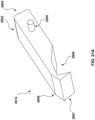
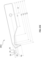
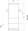
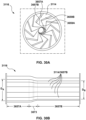
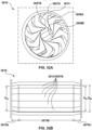
- the crimper includes a plurality of crimper elements that define a crimper channel, each of the crimper elements including a non-planar surface that forms a portion of the crimper channel. Each non-planar surface is configured to apply non-uniform radial compression along a length of the implantable medical device during operation of the crimper when altering the implantable medical device from the uncompressed state to the compressed state.
- the crimper also includes handle configured to operate the crimper. Actuation of the handle decreases a volume of the crimper chamber to transition the implantable medical device from the uncompressed state to the compressed state.
- each crimper element includes a crimper lobe, wherein the crimper lobe includes the non-planar surface, a crimper body coupled to the crimper lobe, and at least one pin coupled to the crimper body.
- the disclosure provides that the crimper lobe comprises a crimper space defined by one or more ramps. At least one of the one or more ramps contacts an adjacent crimper lobe from an adjacent crimper element from the plurality of crimper elements.
- the disclosure provides that the non-planar surface includes a first longitudinal portion and a second longitudinal portion, the second longitudinal portion being disposed closer to a centerline of the crimper chamber than the first longitudinal portion such that the second longitudinal portion is configured to apply a higher radial force onto the implantable medical device than the first longitudinal portion.
- the disclosure provides that the first longitudinal portion extends between 35% and 45% of a total length of the crimper chamber and the second longitudinal portion 3675B extends between 55% and 65% of the total length of the crimper chamber.
- the non-planar surface includes a first longitudinal portion, a second longitudinal portion, and a third longitudinal portion, the second longitudinal portion being disposed between the first and third longitudinal portions, the first and third longitudinal portions being disposed closer to a centerline of the crimper chamber than the second longitudinal portion such that the first and third longitudinal portions are configured to apply a higher radial force onto the implantable medical device than the second longitudinal portion.
- each of the first and third longitudinal portions taper along its length to the second longitudinal portion.
- each of the first and third longitudinal portions extend between 5% and 15% of a total length of the crimper chamber.
- the disclosure provides that the first longitudinal portion extends between 55% and 65% of a total length of the crimper chamber, the second longitudinal portion extends between 25% and 35% of the total length of the crimper chamber and the third longitudinal portion extends between 5% and 15% of the total length of the crimper chamber.
- the disclosure provides that the third longitudinal portion tapers along its length to the second longitudinal portion.
- the non-planar surface includes a first longitudinal portion, a second longitudinal portion, a third longitudinal portion, and a fourth longitudinal portion, the second longitudinal portion being disposed between the first and third longitudinal portions and the third longitudinal portion being disposed between the second and fourth longitudinal portions, the first and fourth longitudinal portions being disposed closer to a centerline of the crimper chamber than each of the second and third longitudinal portions such that the first and fourth longitudinal portions are configured to apply a higher radial force onto the implantable medical device than each of the second and third longitudinal portions, and the second longitudinal portion being disposed closer to the centerline of the crimper chamber than the third longitudinal portion such that the second longitudinal portion is configured to apply a higher radial force onto the implantable medical device than the third longitudinal portion.
- the disclosure provides that the first longitudinal portion tapers along its length to the second longitudinal portion and the fourth longitudinal portion tapers along its length to the third longitudinal portion.
- the disclosure provides that the first longitudinal portion extends between 2% and 8% of a total length of the crimper chamber, the second longitudinal portion extends between 50% and 60% of the total length of the crimper chamber, the third longitudinal portion extends between 25% and 35% of the total length of the crimper chamber, and the fourth longitudinal portion extends between 5% and 15% of the total length of the crimper chamber.
- the present disclosure provides a method for altering an expandable medical device from an uncompressed state to a compressed state.
- the method includes loading the expandable medical device into a crimper chamber of a crimper, actuating a handle of the crimper to operate the crimper.
- the crimper chamber is defined by a plurality of crimper elements, each of the crimper elements including a non-planar surface that forms a portion of the crimper channel.
- Actuation of the handle decreases a volume of the crimper chamber to transition the expandable medical device from the uncompressed state to the compressed state, and each non-planar surface applies non-uniform radial compression along a length of the implantable medical device during operation of the crimper.
- the disclosure provides that a first radial force is applied onto a first section of the implantable medical device by a first longitudinal portion of the non-planar surface and a second radial force is applied onto a second section of the implantable medical device by a second longitudinal portion of the non-planar surface, the second radial force being greater than the first radial force.
- the disclosure provides that the second section of the implantable medical device is denser than the first section of the implantable medical device.
- the disclosure provides that the second section of the implantable medical device includes a valve
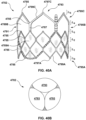
- the disclosure provides that the first section of the implantable medical device includes a plurality of openings formed in a stent of the implantable medical device, the plurality of openings being configured to allow for coronary access when implanted in situ.
- the disclosure provides that the implantable medical device has a substantially uniform profile in the compressed state.
- the disclosure provides that the second section of the implantable medical device is one of an inflow end of the implantable medical device and an outflow end of the implantable medical device.
- the disclosure provides that the non-planar surface includes a first longitudinal portion and a second longitudinal portion, the second longitudinal portion being disposed closer to a centerline of the crimper chamber than the first longitudinal portion such that the second longitudinal portion is configured to apply a higher radial force onto the implantable medical device than the first longitudinal portion.
- the disclosure provides that the first longitudinal portion extends between 35% and 45% of a total length of the crimper chamber and the second longitudinal portion extends between 55% and 65% of the total length of the crimper chamber.
- the non-planar surface includes a first longitudinal portion, a second longitudinal portion, and a third longitudinal portion, the second longitudinal portion being disposed between the first and third longitudinal portions, the first and third longitudinal portions being disposed closer to a centerline of the crimper chamber than the second longitudinal portion such that the first and third longitudinal portions are configured to apply a higher radial force onto the implantable medical device than the second longitudinal portion.
- each of the first and third longitudinal portions taper along its length to the second longitudinal portion.
- each of the first and third longitudinal portions extend between 5% and 15% of a total length of the crimper chamber.
- the disclosure provides that the first longitudinal portion extends between 55% and 65% of a total length of the crimper chamber, the second longitudinal portion extends between 25% and 35% of the total length of the crimper chamber and the third longitudinal portion extends between 5% and 15% of the total length of the crimper chamber.
- the disclosure provides that the third longitudinal portion tapers along its length to the second longitudinal portion.
- the non-planar surface includes a first longitudinal portion, a second longitudinal portion, a third longitudinal portion, and a fourth longitudinal portion, the second longitudinal portion being disposed between the first and third longitudinal portions and the third longitudinal portion being disposed between the second and fourth longitudinal portions, the first and fourth longitudinal portions being disposed closer to a centerline of the crimper chamber than each of the second and third longitudinal portions such that the first and fourth longitudinal portions are configured to apply a higher radial force onto the implantable medical device than each of the second and third longitudinal portions, and the second longitudinal portion being disposed closer to the centerline of the crimper chamber than the third longitudinal portion such that the second longitudinal portion is configured to apply a higher radial force onto the implantable medical device than the third longitudinal portion.
- the disclosure provides that the first longitudinal portion tapers along its length to the second longitudinal portion and the fourth longitudinal portion tapers along its length to the third longitudinal portion.
- the disclosure provides that the first longitudinal portion extends between 2% and 8% of a total length of the crimper chamber, the second longitudinal portion extends between 50% and 60% of the total length of the crimper chamber, the third longitudinal portion extends between 25% and 35% of the total length of the crimper chamber, and the fourth longitudinal portion extends between 5% and 15% of the total length of the crimper chamber.
- a clamshell crimper includes a top iris shell and a base iris shell.
- the top iris shell can be rotated away from the base iris shell to expose a channel for loading and positioning the implantable medical device and the delivery device.
- the channel of the base iris shell and a corresponding channel in the top iris shell form a crimper chamber around the expandable medical device.
- the clamshell crimper can then be actuated to decrease the volume of the crimper chamber though the process of iris-style displacement of lobes.
- a crimper To decrease the volume of the crimper chamber, a crimper includes a plurality of crimper elements.
- the plurality of crimper elements form the crimper chamber around the expandable medical device.
- the crimper can be actuated to decrease the volume of the crimper chamber though the process of iris-style displacement of crimper elements.
- the displacement of the crimper elements is controlled by a handle that actuates a cam.
- the cam includes a plurality of spiral channel that are configured to receive connection pin of the crimper elements. The cam operates to translate the rotation motion of the cam to approximate linear motion of the crimper elements.
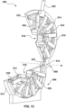
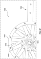
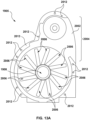
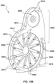
- FIGS. 1A-1E illustrate an example of a clamshell crimper 800 in accordance with an embodiment hereof.
- FIGS. 1A-1E illustrate one example of a crimper and that existing components illustrated in FIGS. 1A-1E may be removed and/or additional components may be added to the clamshell crimper 800.
- FIG. 1A is a side view of a first side of the clamshell crimper 800.
- the clamshell crimper 800 includes a handle 802, a top shell 804 (or top iris shell), and a base shell 806 (or base iris shell).
- the top shell 804 includes a first housing 810
- the base shell 806 includes a first housing 812.
- the top shell 804 and the base shell 806 are coupled at a pivot connection 808.
- the pivot connection 808 allows an angle, 0 , between the top shell 804 and the base shell 806 to be increased or decreased by rotating the top shell 804 away from the base shell about an axis of rotation, R, (illustrated in FIG. 1C ) located at the pivot connection 808.
- the pivot connection 808 is configured to allow the top shell 804 and the base shell 806 to move relative to each other from an open state (as illustrated in FIGS. 1A-1C ) to a closed state (as illustrated in FIG. 7 ). While not illustrated, the clamshell crimper 800 can be coupled to a base or other structure to provide support to the clamshell crimper 800
- an open state for the clamshell crimper 800 defines any angle, ⁇ , between the top shell 804 and the base shell 806 that allows a user to insert an implantable medical device and/or delivery device in the clamshell crimper 800 and that allows a user to view the insertion to properly align the implantable medical device and the delivery device.
- the closed state defines any angle, ⁇ , between the top shell 804 and the base shell 806 in which the clamshell crimper 800 is operating to compress the implantable medical device and to crimp or load the implantable medical device onto a delivery device.
- the angle, ⁇ between the top shell 804 and the base shell 806, when in the open state, can range from approximately 45 degrees to approximately 180 degrees.
- the angle, ⁇ between the top shell 804 and the base shell 806, when in closed state, can be approximately 0 degrees.
- FIG. 1B illustrates a side of a second side of the clamshell crimper 800 that is opposite the first side.
- housings of the second side of the clamshell crimper 800 are removed to illustrate internal components of the clamshell crimper 800.
- the top shell 804 includes the first housing 810 and a second housing (removed in this illustration).
- the base shell 806 includes the first housing 812 and a second housing (removed in this illustration).
- the top shell 804 and the base shell 806 include a plurality of crimper elements 814. As further illustrated in FIG.
- FIG. 1C which is an enlarged perspective view of the top shell 804 and the base shell 806, the crimper elements 814 of the top shell 804 form a top crimper channel 816.
- the crimper elements 814 of the base shell 806 for a bottom crimper channel 818.
- the top crimper channel 816 and the bottom crimper channel 818 form a crimper chamber 820, as illustrated in FIG. 7 , which is a perspective view of the clamshell crimper 800 in the closed state.
- the pivot connection 808 can be any type of mechanical joint or electro-mechanical joint that allows the top shell 804 and the base shell 806 to move relative to each other.
- the pivot connection 808 can include one or more of a hinge, a tab, a rivet, a pivot pin, a pivot joint, an axle, a living hinge, etc.
- the pivot connection 808 can include a movement assistance device to provide a force that assists in the movement of the top shell 804 and the base shell 806 relative to each other.
- the pivot connection 808 can include a spring, a motor, etc.
- the first housing 810 of the top shell 804 can include a tab 819 that extends from a rear portion of the first housing 810.
- the tab 819 includes a pivot connection hole 821 (as illustrated in FIG. 2A discussed below).
- the first housing 812 of the base shell 806 can include a tab 822 that extends from rear potion of the first housing 812.
- the tab 822 includes a pivot connection hole 823 (as illustrated in FIG. 2B discussed below).
- the pivot connection hole 821 and the pivot connection hole 823 can form a concentric hole that operates as the pivot connection 808 when a pin, rivet, bolt, screw or other connecting mechanism is inserted in the concentric hole.
- the pivot connection 808 can include a pin that is positioned in the corresponding concentric hole formed by the pivot connection hole 821 of the first housing 810, the pivot connection hole 823 in the first housing 812, and the pivot connections of the second housing of the top shell 804 and the base shell 806.
- the pin can be a dowel pin, a bolt, and the like. The pin can be formed to a diameter to maintain the corresponding circular openings and cause the pin to operate as a fulcrum.
- the top shell 804 and the base shell 806 can be separate components that can be removably attached at the pivot connection 808 to form the clamshell crimper 800.
- the top shell 804 and the base shell 806 can be part of a single component that fold towards each other, for instance, via a living hinge therebetween, to form an integrated clamshell crimper 800.
- the top shell 804 and the base shell 806 can be formed of any suitable material such as, but not limited to aluminum, stainless steel, or a polymeric material. While the clamshell crimper 800 is described as pivoting at the pivot connection 808, one skilled in the art will realize that top shell 804 and the base shell 806 can move relative to one another using other type of processes and mechanically connections.
- the crimper elements 814 are arranged to partially overlap between the top shell 804 and the base shell 806, respectively, in a first direction.
- the crimper elements 814 of the top shell 804 are arranged to partially overlap to form the top crimper channel 816 at distal ends of the crimper (e.g., described below with reference to FIG. 3A-3D ).
- the crimper elements 814 of the base shell 806 are arranged to partially overlap to form the bottom crimper channel 818 at distal ends of the crimper elements 814 ( e.g ., described below with reference to FIGS. 3A-3D ).
- the top crimper channel 816 and the bottom crimper channel 818 define the crimper chamber 820. That is, when in the closed state, the crimper elements 814 of the top shell 804 and the crimper elements 814 of the base shell 806 form a cylindrical surface of overlapping ends of the crimper elements 814 with a cylindrically-shaped cavity passing through the center, defining the crimper chamber 820.
- the crimper elements 814 can be removable from the top shell 804 and/or base shell 806. As such, the crimper elements 814 may be interchangable with other types of crimper elements configured to accommodate different dimensions and/or configurations of implantable medical devices and/or delivery devices.
- the crimper elements 814 may be formed of any suitable material such as, but not limited to aluminum, stainless steel, or a polymeric material.
- the first housing 810 of the top shell 804 includes a top cam 824.
- the handle 802 is coupled the top cam 824 as further described below with reference to FIGS. 5A and 6A-6C .
- the top cam 824 is also coupled to the crimper elements 814 by rods 826. Each of the rods 826 extends from the top cam 824 to a middle region of one of the crimper elements 814, as described below with reference to FIGS. 3A-3D and 4 .
- the top cam 824 operates to translate the rotational movement of the handle 802 to the crimper elements 814 via the rods 826.
- the first housing 812 of the base shell 806 includes a bottom cam 828.
- the bottom cam 828 is also coupled to the crimper elements 814 by the rods 826.
- Each of the rods 826 extends from the bottom cam 828 to a middle region of one of the crimper elements 814, as described below with reference to FIGS. 3A-3D and 4 .
- the bottom cam 828 operates to translate the movement of the handle 802 (through movement of the top cam 824) to the crimper elements 814 via the rods 826.
- the bottom cam 828 When in the closed state, the bottom cam 828 is coupled to the top cam 824 such that the top cam 824 and the base cam 828 rotate together and function as a single cam. That is, when coupled, the top cam 824 and the bottom cam 828 from a cylindrical ring within the interior of the clamshell crimper 800. Examples of the top cam 824 and bottom cam 828 are described in further detail below with reference to FIGS. 5A and 5B .
- the crimper elements 814 When in the closed state, the crimper elements 814 are displaced by the movement of the handle 802. That is, as the handle 802 is moved, the top cam 824 and the bottom cam 828 rotate and function to translate the rotational motion of the handle 802 into linear motion of the crimper elements 814 via the rods 826, as described below in further detail. As such, the crimper elements 814 of the top shell 804 and the base shell 806 function as an iris to decrease or increase the volume of the crimper chamber 820 through the movement of the handle 802. As illustrated in FIG. 7 , when in a closed state, the crimper chamber 820 can define a volume that approximates a cylinder.
- crimper chamber 820 is described above as defining a cylindrically shaped volume, one skilled in the art will realize that the shape and dimension of the crimper elements 814 can be changed to create a differently shaped volume as required by the implantable medical device being compressed and positioned.
- the clamshell crimper 800 operates to convert an implantable medical device from its uncompressed state to its compressed state. Likewise, the clamshell crimper 800 operates to crimp or load the implantable medical device onto a delivery device.
- the implantable medical device is loaded into the bottom crimper channel 818 and positioned in a direction that is parallel to the axis of rotation, R, of the top shell 804 and the base shell 806.
- the delivery device can also be positioned and aligned relative to the implantable medical device. That is, the implantable medical device can be disposed around the delivery device.
- the clamshell crimper 800 is then moved from the open state to the closed state, and the handle 802 is actuated to convert the implantable medical device from its uncompressed state to its compressed state and load the implantable medical device onto the delivery device.
- a force can be applied to the handle 802 in the direction of the base shell 806.
- the top cam 824 and the bottom cam 828 rotate in the direction that the force is applied to the handle 802.
- the rotation of the top cam 824 and the bottom cam 828 cause the rods 826 to displace inward.
- the inward motion of the rods 826 cause the crimper elements 814 of the top shell 804 and the base shell 806 to displace inward thereby generating the iris effect. That is, the inward motion of the rods 826 is translated to the crimper elements 814 thereby causing the crimper elements to displace inward, as described in further detail below.
- the volume of the crimper chamber 820 decreases and the crimper elements 814 apply a compression force to external surfaces of the implantable medical device to crimp the expandable medical device from its uncompressed state to its compressed state.
- the crimper elements 814 apply a force on the surface of the implantable medical device from various directions as force is applied to the handle 802 thereby compressing the implantable medical device.
- the clamshell crimper 800 can be utilized on any type of implantable medical device that requires a conversion from an uncompressed state to a compressed state.
- the crimper can be applied to any implantable medical device that requires onsite crimping of the implanted medical device onto a catheter, e.g., organic tissue containing valve repair devices.
- the crimper 800 can be used with balloon-expandable medical devices and/or mechanically expandable medical devices.
- the clamshell crimper 800 can be utilized on implantable medical devices that are to be delivered transluminally, e.g ., via a catheter, and need to be loaded onto or into a catheter.
- the implantable medical device can include a heart valve prosthesis, which includes a stent or frame, and a prosthetic valve attached to the interior of the frame.
- the stent/frame may be crimped to have a low profile such that the prosthesis can be delivered through the vessels to a target location in a compressed state, and then expanded at the target location, by a balloon of the delivery device, for instance, to replace the native heart valve.
- a user can properly locate and position such a heart valve prosthesis with respect to the catheter. For example, when a balloon catheter with a non-crimped stent/frame of a heart valve prosthesis is placed within the clamshell crimper 800, a user can visually ensure that the prosthesis is properly located over the balloon of the catheter before proceeding with the crimping operation.
- the open, top loading design of the clamshell crimper 800 provides increased visibility in loading and aligning the implantable medical device and the delivery device as well as rapid fine adjustments.
- the clamshell crimper 800 can be opened to provide easy access to the implantable medical device and the delivery device, the relative alignment of the implantable medical device and the delivery device can be monitored and adjusted without removing the implantable medical device and the delivery device from the clamshell crimper 800.
- a heart valve prosthesis is typically loaded onto a delivery device or catheter at the time of the implantation procedure, e.g ., at the hospital by hospital staff.
- the prosthesis needs to be properly aligned and loaded onto the delivery catheter because, if there is an error, the improperly aligned prosthesis may need to be discarded, which is wasteful and costly.
- the clamshell crimper 800 provides a straightforward and accurate procedure to crimp such a heart valve prosthesis onto a balloon catheter at the hospital. Moreover, the clamshell crimper 800 eliminates complex geometry and machining that normally defines iris crimpers.
- the handle 802 can be formed as a separate component that is attached to the top cam 824. In other embodiments, the handle 802 can be integrated with the top cam 824 to form a single component. In embodiments, the handle 802 can be shaped, sized, designed, and/or configured to accommodate different crimping operations. For example, the handle 802 can be extended and include a pivot point to add more leverage during crimping operations. Likewise, the handle 802 can include a foot pedal that assists in pulling down the handle 802.
- the handle 802 can be formed of any suitable material such as, but not limited to aluminum, stainless steel, or a polymeric material.
- the top shell 804 can include a handle lock mechanism that locks the handle 802 into at a position where the crimper chamber 820 in an open position, e.g., the crimper chamber 820 being open to a maximum diameter.
- the top shell 804 and/or the base shell 806 can include a shell locking mechanism that locks the top shell 804 and the base shell 806 together in a closed state, e.g ., the top shell 804 and base shell 806 being together.
- the clamshell crimper 800 can be moved into an open state, e.g ., the top crimper channel 816 and the bottom crimper channel 818 being separated, by pivoting the top shell 804 away from the base shell 806.
- the top shell 804 can be closed, for example, using the handle 802, and the top shell 804 and the base shell 806 can be locked into the closed state, e.g ., the top shell 804 and base shell 806 being together.
- the handle 802 can then be unlocked by disengaging the handle lock mechanism to perform crimping operations.
- the dual locking can prevent either the top crimper channel 816 the top shell 804 or bottom crimper channel 818 of the base shell 806 from moving to the closed position while the other half is in the open position.
- the clamshell crimper 800 can also include one or more stops that operate to physically stop the crimper handle 802 at one or more predetermined positions that correspond to one or more predetermine diameters to which the implantable medical device may be crimped or compressed.
- the clamshell crimper 800 can include a first stop and a second stop, such as a first stop 1950 and a second stop 1952 as illustrated in FIG. 12B and discussed in detail below.
- the first stop and the second stop provide a surface that stop the movement of the handle 802 in the downward direction.
- the first stop and the second stop provide a stop position of the handle 802 that corresponding to a predetermined diameter of the crimper chamber 820.
- the first stop and the second stop operate a physically stops to allow an implantable medical device to be compressed to a predetermined diameter or compression.
- the first stop can operate to allow an implantable medical device to be partially compressed.
- the second stop can operate to allow an implantable medical device to be fully compressed.
- the first stop and the second stop can be removably coupled to the top shell 804 and/or base shell 806. As such, the first top and/or the second stop can be added and/or removed to allow an implantable medical device to be compressed to predetermined diameters
- the components of the clamshell crimper 800 are described above with relative terms “first,” “second,” “proximal,” and “distal,” one skilled in the art will realize that the use of these terms is intended only to identify components of the clamshell crimper 800 and do not define any preferred or ordinal arrangement of the components of the crimper 800.
- the implantable medical device is described as being positioned in the bottom crimper channel 818 during operation, in an embodiment, the implantable medical device can be positioned in the top crimper channel 816.
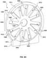
- FIG. 2A illustrates a detailed view of components of the first housing 810 of the top shell 804.
- FIG. 2A illustrates one example of a housing of the top shell 804 and that existing components illustrated in FIG. 2A may be removed and/or additional components may be added to the first housing 810.
- top shell 804 includes a second housing that may include the same components as illustrated in FIG. 2A .
- the second housing may be formed as a "mirror" of the first housing 810 and can be coupled to the first housing 810 to form the top shell 804.
- the first housing 810 includes a side plate 902 with an interior surface 903 and an exterior surface (not shown) opposite the interior surface.
- the side plate 902 can be constructed as a semi-cylindrical plate with a semi-cylindrical opening 908.
- the semi-cylindrical opening 908 allows access to the top crimper channel 816 formed by the crimper elements 814.
- Crimper element channels 904 are formed in the interior surface 903 of the side plate 902.
- the crimper element channels 904 can each be formed as a rectangular groove or channel that extends inward from an outer radius of the side plate 902 towards the semi-cylindrical opening 908.
- the crimper element channels 904 can be positioned in an arc, at equal distances, along the interior surface 903 of the side plate 902.
- the crimper element channels 904 are coupled to a center cavity 906 formed in the interior surface 903 of the side plate 902.
- the center cavity 906 can be formed as a semi-circular cavity having the approximately same depth as the crimper element channels 904.
- the side plate 902 also includes a cam channel 910 formed within the interior surface 903 of the side plate 902.
- the cam channel 910 can extend in a semi-circular arc from a bottom surface 911 of the side plate 902.
- the cam channel 910 can be configured to receive and retain the top cam 824 and configured to allow the top cam 824 to move ( e.g ., rotate) within the top shell 804.
- the cam channel 910 can be formed to a depth that is less than the crimper element channel 904.
- the cam channel 910 can be formed to a width that accommodates the top cam 824.
- the side plate 902 also include a handle stop 912 that extends from the interior surface 901 of the side plate 902.
- the handle stop 912 can extend in an arc partially around the circumference of the side plate 902 from the tab 819 to a stop position, thereby defining a handling opening 905.
- the handle stop 912 can operate as a stop from the handle 802 when the handle 802 is moved.
- the side plate 902 also includes the tab 819 that extends from a side surface of the side plate 902. While FIG. 2A illustrates the tab 819 being formed as a unitary component with the side plate 902, one skilled in the art will realize that the tab 819 can be a separate component that is coupled to the side plate 902.
- FIG. 2B illustrates a detailed view of components of the first housing 812 of the base shell 806.
- FIG. 2B illustrates one example of a housing of the base shell 806 and that existing components illustrated in FIG. 2B may be removed and/or additional components may be added to the first housing 812.
- base shell 806 includes a second housing that may include the same components as illustrated in FIG. 2B .
- the second housing may be formed as a "mirror" of the first housing 812 and can be coupled to the first housing 812 to form the base shell 806.
- the first housing 812 includes a side plate 952 with an interior surface 953 and an exterior surface (not shown).
- the side plate 952 can be constructed as a semi-cylindrical plate with a semi-cylindrical opening 958.
- the semi-cylindrical opening 958 allows access to the bottom crimper channel 818 formed by the crimper elements 814.
- Crimper element channels 954 are formed in the interior surface 953 of the side plate 952.
- Each of the crimper element channels 954 can be formed as a rectangular groove or channel that extends inward from an outer radius of the side plate 952 towards the semi-cylindrical opening 958.
- the crimper element channels 954 can be positioned in an arc, at equal distances, along the interior surface 953 of the side plate 952.
- the crimper element channels 954 are coupled to a center cavity 956 formed in the interior surface 953 of the side plate 952.
- the center cavity 956 can be formed as a semi-circular cavity having approximately the same depth as the crimper element channels 954.
- the side plate 952 also includes a cam channel 960 formed within the interior surface 953 of the side plate 952.
- the cam channel 960 can extend in a semi-circular arc from a top surface 961 of the side plate 952.
- the cam channel 960 can be configured to receive and retain the bottom cam 828 and configured to allow the bottom cam 828 to move ( e.g ., rotate) within the base shell 806.
- the cam channel 960 can be formed to a depth that is less than the crimper element channels 954.
- the cam channel 960 can be formed to a width that accommodates the bottom cam 828.
- the side plate 952 also includes the tab 822 that extends from a side surface of the side plate 952. While FIG. 2B illustrates the tab 822 being formed as a unitary component with the side plate 952, one skilled in the art will realize that the tab 822 can be a separate component that is coupled to the side plate 952.
- FIG. 2C illustrates an enlarged perspective view of the crimper element channels 904 and a portion of the center cavity 906, according to an embodiment hereof. While the configuration and dimensions of the side plate 902 of the top shell 802 are described with reference to FIG. 2C , one skilled in the art will realize that the configuration described in FIG. 2C can also be applied to the configuration of the side plate 952 of the base shell 806
- the side plate 902 is formed having a radius that extends from a center point 980 of the semi-cylindrical opening 908 to a side surface 982 of the side plate 902.
- the radius can be formed to a length that accommodates the crimper elements 814 and allows for movement of the crimper elements within the top shell 804
- the radius can be formed to a length of approximately 112.5 mm.
- the crimper element channels 904 of the side plate 902 are formed to a width and depth to accommodate the crimper elements 814 when the side plate 902 of the first housing 810 is mated with a side plate of the second housing of the top shell 804.
- the crimper element channels 804 of the side plate 902 are formed to a length and the center cavity 906 is formed to a radius that allows the crimper elements 814 move and perform the crimping operations of the clamshell crimper 800.
- the crimper element channels 904 can be formed to a width of approximately 15.0 mm.
- the crimper element channels 904 can be formed to a depth of approximately 8.5 mm, from the interior surface 903 of the side plate 902.
- the crimper element channels 904 can be formed to a length of approximately 60.5 mm.
- the center cavity can be formed having a radius of approximately 40.0 mm from the center point 980 to the distal end of the crimper element channel 904.
- each of the crimper element channels 904 are formed in an arc around the side plate 902.
- each of the crimper element channels 904 are spaced in the arc at an angle, ⁇ , from an adjacent crimper element channel 904.
- each of the crimper element channels 904 are spaced at an angle, ⁇ , of approximately 30 degrees.
- each of the crimper element channels 904 can be aligned to be offset relative to the Radius of the side plate 902 by an angle, ⁇ . For example, as illustrated in FIG.
- the angle, ⁇ can be defined as an angle between the Radius and a sidewall 984 of a crimper element channel 904, when measured at an intersection 986 of the Radius and the sidewall 984.
- the offset can cause the crimper elements 814 to move in a direction that is offset from the center point 980.
- the crimper element channels 906 can be offset by an angle, ⁇ , that is approximately 15 degrees.
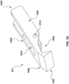
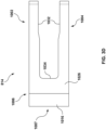
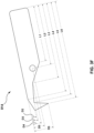
- FIGS. 3A-3D illustrate detailed views of a crimper element 814, according to an embodiment hereof.
- FIGS. 3A-3D illustrate one example of a crimper element and that existing components illustrated in FIGS. 3A-3D may be removed and/or additional components may be added to the crimper element 814. While only one crimper element 814 is discussed, one skilled in the art will realize that the crimper elements 814 of the top shell 804 and the base shell 806 may have the same configuration and include the same components as the crimper element 814 described in FIGS. 3A-3D .
- the crimper element 814 has a first leg 1002, a second leg 1004, and a crimper lobe 1006 coupled to the first leg 1002 and the second leg 1004.
- the first leg 1002 and the second leg 1004 extend, parallel to a long axis of the crimper element 814, from a proximal end 1005 of the crimper element 814 to the crimper lobe 1006.
- the first leg 1002 and the second leg 1004 are spaced apart and define a rod channel 1010.
- the crimper lobe 1006 extends from the first leg 1002 and the second leg 1004 to a distal end 1007 of the crimper element 814.
- the crimper lobe 1006 is configured to define a crimper space 1008.
- the crimper space 1008 is configured to accommodate an adjacent crimper element 814.
- the crimper element 814 includes a top surface 1026, a bottom surface 1028, and a distal surface 1030 formed at the ends of the first leg 1002 and the second leg 1004.
- the crimper lobe 1006 includes a first exterior ramp 1014 and a second exterior ramp 1016.
- the crimper lobe 1006 also includes a first interior ramp 1018 and a second interior ramp 1020.
- the intersection of the first leg 1002 and the crimper lobe 1006 and the intersection of the second leg 1004 and the crimper lobe 1006 form a sloped edge 1022.
- FIG. 3B which is a bottom view
- the first interior ramp 1018, the second interior ramp 1020, and the sloped edge 1022 define the crimper space 1008.
- the first exterior ramp 1014 and the second exterior ramp 1016 form a surface between the top surface 1026 and the distal end 1007 and the bottom surface 1028.
- the first exterior ramp 1014 and the second exterior ramp 1016 can be formed at angles relative to the top surface 1026 and the bottom surface 1028.
- the first interior ramp 1018 and the second interior ramp 1020 can be formed at angles relative to the top surface 1026 and the bottom surface 1028.
- the intersection of the first leg 1002 and the crimper lobe 1006 and the intersection of the second leg 1004 and the crimper lobe 1006 form a sloped edge 1022.
- the first leg 1002 and second leg 1004 include interior surfaces 1032 and 1033 and a sloped edge 1036 between the interior surface 1032, 1033.
- a rod channel 1010 is defined by the interior surfaces 1032 and 1033, the sloped edge 1036, and a proximal end 1034 of the crimper lobe 1006.
- the rod channel 1010 is configured to accommodate one of the rods 826.
- the crimper elements 814 also includes connection holes 1012.
- the connection holes 1012 are formed in the first leg 1002 and the second leg 1004.
- the crimper elements 814 can include two connection holes 1012 that are positioned at opposing locations on the first leg 1002 and the second leg 1004.
- connection holes 1012 can be configured to receive a pin that passes through the two connection holes and a connection hole of the rod 826.
- the pin can be a dowel pin, a bolt, and the like.
- the pin can be formed to a diameter to maintain the corresponding circular openings and cause the pin to operate as a fulcrum.
- the connection holes 1012 operate to moveably couple the crimper elements 814 to the rods 826.
- the rods 826 are coupled within the rod channel 1010.
- the rod channels 1010 allow the rods 826 to rotate relative to the crimper elements 814 during operation of the clamshell crimper 800.
- the crimper element 814 are configured to work in combination to produce the iris effect of the clamshell crimper 800.
- FIG. 3E is an enlarged side view of several crimper element 814 in which the crimper elements 814 are positioned in a fully open position. As illustrated, a first exterior ramp 1014 of a first crimper element 814 rests against a first interior ramp 1018 of a second crimper element 814, forming an overlap. The overlap of the crimper elements 814 defines the crimper chamber 820.
- the handle 802 is actuated in a downward motion (counter-clockwise direction as illustrated in FIG.
- the cam (the top cam 824 illustrated in FIG. 3E ) thereby causing the cam (the top cam 824 illustrated in FIG. 3E ) to rotate.
- the rotation of the top cam 824 forces the rods 826 inward.
- the motion of the rods 826 forces the crimper elements 814 inward.
- the crimper elements 814 move inward generally towards the center of the crimper chamber 820.
- the space available for the crimper elements 814 to occupy is reduced.
- the space between the crimper elements 814 is reduced.
- the first exterior ramp 1014 of the first crimper element 814 slides against the first interior ramp 1018 of the second crimper element 814.
- the area of the crimper chamber 820 is reduced.
- each crimper element 814 can range from approximately 25mm to approximately 50mm and the length of each crimper element 514 can range from approximately 1 mm to approximately 40mm.
- the slope of the first exterior ramp 1014 and the second exterior ramp 1016 (angle relative to the top surface 1026 and the bottom surface 1028) can depend on the number of crimper elements included in the clamshell crimper 800.
- the slope of the first interior ramp 1018, the second interior ramp 1020, and the sloped edge 1022 can depend on the number of crimper elements included in the clamshell crimper 800.
- the slope can be determined by dividing 360 degrees by the number of crimper elements 814 in the clamshell crimper 800. In an embodiment, the number of crimper elements can range from 10 to 12.
- the first interior ramp 1018, the second interior ramp 1020, and the sloped edge 1022 are configured to contact a neighboring crimper element and generate the iris effect when the crimper elements are displaced.
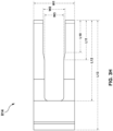
- FIGS. 3F-3H illustrates examples of dimensions for a crimper element 814 having a 30mm configuration, according to an embodiment hereof.
- reference numbers for the crimper element 814 have been omitted and can be found in FIGS. 3A-3D .
- Table 1 below describes the dimension illustrated in FIGS. 3F-3H and provides example values for the dimensions.
- the values for the dimension are one example, and the crimper element 814 can have different values for the dimension based on the particular configuration of the clamshell crimper 800 and the crimping application.
- FIG. 4 illustrates an example of the rod 826.
- the rod 826 is formed as a rectangular bar 1102 with connection holes 1104.
- the rectangular bar 1102 can include rounded ends 1106 that are formed in a semi-cylindrical shape.
- One of the connection holes 1104 operates to moveably couple the crimper elements 814 to the rod 826.
- a first of the connection holes 1104 align with the connection holes 1012 of the crimper element 814.
- the first of the connection holes 1104 can be configured to receive a pin that passes through the two connection holes 1012 of the crimper element 814.
- the pin can be a dowel pin, a bolt, and the like.
- the pin can be formed to a diameter to maintain the corresponding circular openings and cause the pin to operate as a fulcrum.
- a second of the connection holes 1104 aligns with a connection hole of the top cam 824 or bottom cam 828, described below.
- the second of the connection holes 1104 can be configured to receive a pin that passes through the connection holes of the top cam 824 or bottom cam 828.
- the pin can be a dowel pin, a bolt, and the like.
- the pin can be formed to a diameter to maintain the corresponding circular openings and cause the pin to operate as a fulcrum.
- the combination of the pin and the connection hole 1104 allow the rod 826 to rotate about the pin.
- FIG. 5A illustrates a side view of the top cam 824, according to an embodiment hereof.
- FIG. 5A illustrates one example of a cam and that existing components illustrated in FIG. 5A may be removed and/or additional components may be added to the top cam 824.
- the top cam 824 includes a semi-circular ring 1202.
- the semi-circular ring 1202 includes a handle support 1204, rod connection holes 1206, and handle connection holes 1208.
- a second of the connection holes 1104 of a rod 826 aligns with a connection hole 1206 of the top cam 824 or bottom cam 828, described below.
- the second of the connection holes 1104 can be configured to receive a pin that passes through the connection holes 1206 of the top cam 824 or bottom cam 828, whether directly or through a connection member of the handle 802.
- the pin can be a dowel pin, a bolt, and the like.
- the semi-circular ring 1202 is formed to a width that is slightly smaller than the cam channel 910.
- top cam 824 This allows the top cam 824 to move within the cam channel 910 when a force is applied to the handle 802, thereby translating the force to the semi-circular ring 1202 and causing the top cam 824 to rotate clockwise or counter-clockwise (depending on the direction of the force applied to the handle 802).
- FIG. 5B illustrates a side view of the bottom cam 828, according to an embodiment hereof.
- FIG. 5B illustrates one example of a cam and that existing components illustrated in FIG. 5B may be removed and/or additional components may be added to the bottom cam 828.
- the bottom cam 828 includes a semi-circular ring 1252.
- the semi-circular ring 1252 includes rod connection holes 1206 and a cam connection member 1253 with connection holes 1254.
- the rod connection holes 1206 can be configured to receive a pin that passes through a second of the connection holes 1104 of a rod 826.
- the semi-circular ring 1252 is formed to a width that is slightly smaller than the cam channel 960. This allows the bottom cam 828 to move within the cam channel 960 when a force is applied to the handle 802 and thereby translated to the semi-circular ring 1252 via the top cam 824.
- the cam connection member 1253 operates to couple the bottom cam 828 to the top cam 824.
- the connection holes 1254 are configured to receive a connection device to couple the cam connection member 1252 to the bottom cam 828
- the connection device can be any type of device to couple the cam connection member 1253 to the bottom cam 828 such as a bolt, screw, pin, etc.
- the cam connection member 1253 can be integrated with the bottom cam 828 as a single component.
- FIGS. 6A-6C illustrate detailed views of the handle 802, according to an embodiment hereof.
- FIGS. 6A-6C illustrate one example of a handle and that existing components illustrated in FIGS. 6A-6C may be removed and/or additional components may be added to the handle 802.
- the handle 802 includes a handle bar 1301 and a handle base 1302.
- the handle base 1302 includes a handle bar connection member 1304 and a top cam connection member 1306.
- the handle bar connection member 1304 include a connection hole for receiving a portion of the handle bar 1301.
- the top cam connection member 1306 includes connection holes 1310 for coupling the handle base 1302 to the top cam 824.
- the connection holes 1310 are configured to receive a connection device to couple the top cam connection member 1306 to the top cam 824.
- the connection device can be any type of device to couple the top cam connection member 1306 to the top cam 824 such as a bolt, screw, pin, etc.
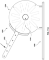
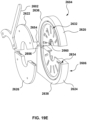
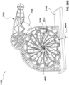
- FIGS. 8A-8F illustrate an example of a crimper 1500 in accordance with an embodiment hereof.
- FIGS. 8A-8F illustrate one example of a crimper and that existing components illustrated in FIGS. 8A-8F may be removed and/or additional components may be added to the crimper 1500.
- FIG. 8A is a first side view of a first side of the crimper 1500.
- the crimper 1500 includes a handle 1502, a crimper housing 1504, and a base 1506.
- the crimper housing 1504 includes a first side 1503 as illustrated in FIG. 8A and a second side 1505 positioned opposite the first side 1503 as illustrated in FIG. 8B , which is a second side view of the crimper 1500.
- the first side 1503 of the crimper housing 1504 can be coupled to the second side 1505 of the crimper housing 1504 by one or more connectors 1507.
- the connectors 1507 can be any type of device to couple the first side 1503 of the crimper housing 1504 to the second side 1505 of the crimper housing 1504 such as a bolt, screw, pin, etc.
- the crimper housing 1504 includes an opening 1508 from a first side 1503 of the crimper housing 1504 to a second side 1505 of the crimper housing 1504.
- the opening 1508 can be formed in an approximate circular cross-sectional shape.
- the opening 1508 can allow access to a crimper chamber 1516 of the crimper 1500 as described in further detail below.
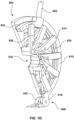
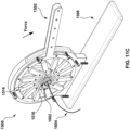
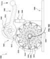
- FIGS. 8C and FIG. 8D illustrate a perspective view and a side view of the crimper 1500, respectively, in which the second side 1505 of the crimper housing 1504 has been removed to illustrate internal components of the crimper 1500.
- the handle 1502 extends into the crimper housing 1504 and includes two cams 1512.
- the cams 1512 are coupled to a plurality of crimper elements 1514 by rods 1518.
- the crimper elements 1514 form the crimper chamber 1516.
- Each of the rods 1518 extends from the two cams 1512 to a middle region of one of the crimper elements 1514, as explained in further details with reference to FIGS. 10A and 10B .
- Each of the cams 1512 can be formed as a circular ring in which the rods 1518 are movably coupled between the two cams 1512. That is, when the two cams 1512 rotate in response to movement of the handle 1512, the rods 1518 are allowed to rotate relative to the two cams 1512. Likewise, the rods 1518 are rotatably coupled to the crimper elements 1514.
- the crimper element 1514 can be configured and include components similar to those described above in FIGS. 3A-3D .
- the rods 1518 can be configured and can include components similar to those described above in FIG. 4 .
- the two cams 1512 operate to translate the rotational movement of the handle 1502 to the crimper elements 1514 via the rods 1518.
- the crimper elements 1514 are displaced by the movement of the handle 1502. That is, as the handle 1502 is moved, the two cams 1512 rotate and the rods 1518 function to translate the rotational motion of the two cams 1512 into linear motion of the crimper elements 1514.
- the crimper elements 1514 of the crimper housing 1504 function as an iris to decrease or increase the volume of the crimper chamber 1516 through the movement of the handle 1502, as described below in further detail.
- the crimper chamber 1516 can define a volume that approximates a cylinder.
- crimper chamber 1516 is described above as defining a cylindrically shaped volume, one skilled in the art will realize that the shape and dimension of the lobes can be changed to create a differently shaped volume as required by the implantable medical device being compressed and positioned.
- the base 1506 of the crimper 1500 can be formed as a rectangular plate.
- the base 1506 can be formed to a width and length that extends beyond the length and width of the crimper housing 1504 and the handle 1502.
- the base 1506 provides a stable platform for operating the crimper 1500 during crimping procedures.
- the crimper housing 1504 is coupled to the base 1506 by one or more connectors 1510.
- the connectors 1510 can be any type of device to couple the crimper housing 1504 to the base 1506 such as a bolt, screw, pin, etc.
- the crimper 1500 operates to convert an implantable medical device from its uncompressed state to its compressed state.
- the implantable medical device is loaded into the crimper chamber 1516 and positioned in a direction that is parallel to the long axis of the base 1506.
- the delivery device can also be positioned and aligned relative to the implantable medical device. That is, the implantable medical device can be disposed around the delivery device.
- the handle 1502 is actuated to convert the implantable medical device from its uncompressed state to its compressed state and load the implantable medical device onto the delivery device.
- a force can be applied to the handle 1502 in the direction of the base 1506.
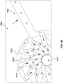
- FIG. 8E an enlarged view of the crimper 1500 with the crimper housing 1504 removed
- the two cams 1512 rotate in the direction that the force is applied to the handle 1502.
- the rotational movement of the two cams 1512 is translated to approximate linear motion by the rods 1518 and transferred to the crimper elements 1514.
- the overlap of the crimper elements 1514 define the crimper chamber 1516.
- each rod 1518 is fixed at one end to the cams 1512 and at the opposite end to one of the crimper elements 1514 (rotation is allowed), when the cams 1512 are rotated, the distance between the connection of the rod 1518 to the cams 1512 and the connection of the rod 1518 to the crimper element 1514 must remain the same. However, as the cams 1512 are rotated, that distance can only remain the same if the crimper element 1514 is pushed radially inward by the rods 1518, as shown by comparing FIG. 8E to FIG.
- the crimper elements 1514 are displaced inward generating the iris effect. As such, the volume of the crimper chamber 1516 decreases and the crimper elements 1514 apply a compression force to external surfaces of the implantable medical device to crimp the expandable medical device from its uncompressed state to its compressed state. For example, if the implantable medical device is round or cylindrical in shape, the crimper elements apply a force on the surface of the implantable medical device from various directions as force is applied to the handle 1502 thereby compressing the implantable medical device.
- the crimper 1500 can be utilized on any type of implantable medical device that requires a conversion from an uncompressed state to a compressed state.
- the crimper can be applied to any implantable medical device that requires onsite crimping of the implanted medical device onto a catheter, e.g ., organic tissue containing valve repair devices.
- the crimper 1500 can be used with balloon-expandable medical devices and/or mechanically expandable medical devices.
- the crimper 1500 can be utilized on implantable medical devices that are to be delivered transluminally, e.g ., via a catheter, and need to be loaded onto or into a catheter.
- the implantable medical device can include a heart valve prosthesis, which includes a stent or frame, and a prosthetic valve attached to the interior of the frame.
- the stent/frame may be crimped to have a low profile such that the prosthesis can be delivered through the vessels to a target location in a compressed state, and then expanded at the target location, by a balloon of the delivery device, for instance, to replace the native heart valve.
- a heart valve prosthesis is typically loaded onto a delivery device or catheter at the time of the implantation procedure, e.g ., at the hospital by hospital staff.
- crimper 1500 While the components of the crimper 1500 are described above with relative terms “first,” “second,” “proximal,” and “distal,” one skilled in the art will realize that the use of these terms is intended only to identify components of the crimper 1500 and do not define any preferred or ordinal arrangement of the components of the crimper 1500.
- FIGS. 9A and 9B illustrate detailed views of components of the second side 1505 of the crimper housing 1504.
- FIGS. 9A and 9B illustrate one example of a side of the crimper housing 1504 and that existing components illustrated in FIGS. 9A and 9B may be removed and/or additional components may be added to the second side 1505.
- the second side 1505 of the crimper housing 1504 is only discussed below, one skilled in the art will realize that crimper housing 1504 includes a first side that may include the same components as illustrated in FIGS. 9A and 9B .
- the first side 1503 of the crimper housing 1504 may be formed as a "mirror" of the second side 1505 of the crimper housing 1504 and can be coupled to the second side 1505 to form the crimper housing 1504.
- the second side 1505 of the crimper housing 1504 includes an interior surface 1602 and an exterior surface (not shown).
- the second side 1505 can be constructed as a cylindrical plate with a base portion 1610 that is formed in an approximate partial rectangle shape.
- the second side 1505 can include the opening 1508.
- the cylindrical opening 1508 allows access to the crimper chamber 1516 formed by the crimper elements 1514.
- the second side 1505 also includes a handle opening 1604 that is formed by a handle stop 1613 that extends from the interior surface 1602 of the second side 1505.
- the handle stop 1613 can extend in an arc partially around the circumference of the interior surface 1602 of the second side 1505 thereby forming the handle opening 1604.
- the handle stop 1613 can operate as a stop in both the clockwise and counter-clockwise direction for the handle 1502 when the handle 1502 is moved.
- Crimper element channels 1606 are formed in the interior surface 1602 of the second side 1505.
- the crimper element channels 1606 can be formed as a rectangular groove or channel that extends from inward from an outer radius of the second side 1505 towards the opening 1508.
- the crimper element channels 1606 can be positioned in an arc, at equal distances, along the interior surface 1602 of the second side 1505.
- the crimper element channels 1606 are coupled to a center cavity 1608 formed in the interior surface 1602 of the second side 1505.
- the center cavity 1608 can be formed as a circular cavity having approximately the same depth as the crimper element channels 1606.
- the crimper element channels 1606 and the center cavity 1608 can be configured to moveably secure the crimper elements 1514 within the crimper housing 1504.
- FIG. 9B which is an enlarged perspective view of the crimper element channels 1606 and a portion of the center cavity 1608, the crimper element channels 1606 of the second side 1505 are formed to a width and depth to accommodate the crimper elements 1514 when the second side 1505 of the crimper housing 1504 is mated with the first side 1503 of the crimper housing 1504.
- the second side 1505 of the crimper housing 1504 can be formed to a configuration and dimensions as described above with reference to FIGS. 2A-2C .
- FIGS. 10A and 10B illustrate detailed views of the handle 1502, according to an embodiment hereof.
- FIGS. 10A and 10B illustrate one example of a handle and that existing components illustrated in FIGS. 10A and 10B may be removed and/or additional components may be added to the handle 1502.
- the handle 1502 includes a handle bar 1702 that is coupled to the two cams 1512.
- the handle bar 1702 can be formed as an integrated extension of the cams 1512.
- the handle bar 1702 can include a spacer member 1703 that is coupled between the sides of the handle bar 1702.
- the two cams 1512 can be coupled by spacers 1704 and pins 1706.
- the spacers 1704 and pins 1706 serve as a connection point for the rods 1518.
- the spacers 1704 and pins 1706 can pass through a second of the connection holes 1104 of a rod 1518, as similarly described above with reference to a rod 826.
- a pin 1706 can be a dowel pin, a bolt, and the like.
- a spacer 1704 can be a hollow cylindrical tube and the like.
- the handle bar 1702 can include connection holes 1716.
- the connection holes 1716 can be configured to receive pins that couple the spacer member 1703 between the sides of the handle bar 1702.
- the cam 1512 can also include connection holes 1718 for receiving the pins 1706. Additionally, while one of the cams 1512 is discussed below with reference to FIG. 10B , one skilled in the art will realize that both cams 1512 may include the same components as illustrated in FIG. 10 .
- FIGS. 11A-11D illustrate an example of the operation of the crimper 1500 in accordance with an embodiment hereof.
- FIGS. 11A-11D illustrate one example of the operation of the crimper 1500 and that existing components illustrated in FIGS. 11A-11D may be removed and/or additional components may be added to the crimper 1500 without departing from the scope of the present invention.
- FIGS. 11A-11D illustrate only a few operating states in order to illustrate the operation of the crimper 1500, and will realize that the crimper 1500 can assume other operational states without departing from the scope of the present invention.
- an implantable medical device 1802 and a delivery device 1804 can be loaded into the crimper chamber 1516 of the crimper housing 1504.
- an implantable medical device 1802 can be placed in crimper chamber 1516 of the crimper housing 1504.
- the delivery device 1804 can be positioned relative to the implantable medical device 1802.
- the crimper elements 1514 form the crimper chamber 1516.
- a force is applied to the handle 1102 in the direction of the base 1106.
- the two cams 1512 rotate in a clockwise direction.
- force is applied to the crimper elements 1514 through the rods 1518.
- the crimper elements 1514 displace inward, e.g ., each crimper element 1514 slides along the interior ramps of a neighboring crimper element 1514.
- the displacement of the crimper elements 1514 inward creates an iris effect thereby decreasing the volume of the crimper chamber 1516.
- the crimper elements 1514 apply a compression force to external surfaces of the medical device 1802 to crimp alter the medical device 1802 from its uncompressed state to its compressed state.
- FIGS. 12A and 12B illustrate another example of a crimper 1900 in accordance with an embodiment hereof.
- FIGS. 12A and 12B illustrate one example of a crimper and that existing components illustrated in FIGS. 12A and 12B may be removed and/or additional components may be added to the crimper 1900.
- FIG. 12A is a perspective view of the crimper 1900.
- the crimper 1900 includes a handle 1902, a crimper housing 1904, and a base 1906.
- the crimper housing 1904 includes a first side 1903 and a second side 1905 positioned opposite the first side 1903.
- the first side 1903 of the crimper housing 1904 can be coupled to the second side 1905 of the crimper housing 1904 by one or more connectors 1907.
- the connectors 1907 can be any type of device to couple the first side 1903 of the crimper housing 1904 to the second side 1905 of the crimper housing 1904 such as a bolt, screw, pin, etc.
- the crimper housing 1904 includes an opening 1908 from a first side 1903 of the crimper housing 1904 to a second side 1905 of the crimper housing 1904.
- the opening 1908 can be formed in an approximate circular cross-sectional shape.
- the opening 1908 can allow access to a crimper chamber 1916 of the crimper 1900 as described in further detail below.
- FIG. 12B illustrates a perspective view of the crimper 1900 in which the first side 1903 of the crimper housing 1904 has been removed to illustrate internal components of the crimper 1900.
- the crimper 1500 includes a cam 1910.
- the handle 1902 extends into the crimper housing 1904 and includes a gear 1912.
- the gear 1912 is coupled to the cam 1910 at a gear portion 1913 of the cam 1910.
- the gear 1912 of the handle 1902 includes teeth that mate with teeth of the gear portion 1013 of the cam 1910.
- the crimper housing 1904 also includes a plurality of crimper elements 1914.
- the cam 1910 is coupled to a plurality of crimper element 1914 by rods 1918.
- the crimper elements 1914 form the crimper chamber 1916.
- Each of the rods 1918 extends from the cam 1910 to a middle region of one of the crimper elements 1914, as explained in further detail with reference to FIGS. 15A , 15B , and 16A-16D .
- the cam 1910 can be formed as a circular ring to which the rods 1918 are rotatably coupled. That is, when the cam 1910 rotates in response to movement of the handle 1912, the rods 1918 are allowed to rotate relative to the cam 1910.
- the rods 1918 are rotatably coupled to the crimper elements 1914. That is, when the rods 1918 move in response to the rotation of the cam 1910, the crimper elements 1914 are allowed to rotate relative to the rods 1918.
- the crimper elements 1914 can be configured and can include components similar to those described above in FIGS. 3A-3D .
- the rods 1918 can be configured and can include components similar to those described above in FIG. 4 .
- the crimper elements 1914 can be configured and can include components as described below in FIGS. 16A-16D .
- the rods 1918 can be configured and can include components as described below in FIGS. 15A and 15B
- the cam 1910 operates to translate the rotational movement of the handle 1902 to the crimper elements 1914 via the rods 1918.
- the crimper elements 1914 are displaced by the movement of the handle 1902. That is, as the handle 1902 is moved, the cam 1910 rotates and functions to translate the rotational motion of the handle 1902 into linear motion of the crimper elements 1914 via the rods 1918.
- the crimper elements 1914 of the crimper housing 1904 function as an iris to decrease or increase the volume of the crimper chamber 1916 through the movement of the handle 1902, as described below in further detail.
- the crimper chamber 1916 can define a volume that approximates a cylinder.
- crimper chamber 1916 is described above as defining a cylindrical shaped volume, one skilled in the art will realize that the shape and dimension of the lobes can be changed to create a differently shaped volume as required by the implantable medical device being compressed and positioned.
- the base 1906 of the crimper 1900 can be formed as a rectangular plate.
- the base 1906 can be formed to a width and length that extends beyond the length and width of the crimper housing 1904 and the handle 1902.
- the base 1906 provides a stable platform for operating the crimper 1500 during crimping procedures.
- the crimper housing 1904 is coupled to the base 1906 by one or more connection devices 1920.
- the connection devices 1920 can be any type of device to couple the crimper housing 1904 to the base 1906 such as a bolt, screw, pin, etc.
- the crimper 1900 operates to convert an implantable medical device from its uncompressed state to its compressed state.
- the implantable medical device is loaded into the crimper chamber 1916 and positioned in a direction that is parallel to the long axis of the base 1906.
- the delivery device can also be positioned and aligned relative to the implantable medical device.
- the crimper 1900 is then moved from the open state to the closed state, and the handle 1902 is actuated to convert the implantable medical device from its uncompressed state to its compressed state and load the implantable medical device onto the delivery device.
- a force can be applied to the handle 1902 in the direction of the base 1906.
- the cam 1910 rotate in the direction that is opposite to the force is applied to the handle 1902.
- the handle 1902 can be actuated in a downward motion thereby causing the cam 1912 to rotate in a clockwise direction.
- causing the cam 1910 to rotate in a clockwise direction because each rod 1918 is fixed at one end to the cam 1910 and at the opposite end to one of the crimper elements 1914 (rotation is allowed), when the cam 1910 is rotated, the distance between the connection of the rod 1918 to the cam 1910 and the connection of the rod 1918 to the crimper element 1914 must remain the same. However, as the cam 1910 is rotated, that distance can only remain the same if the crimper element 1914 is pushed radially inward by the rods 1918. Thus, rotation of the cam 1910 forces the crimper elements 1914 inward via the rods 1918 inward. In particular, the crimper elements 1914 move inward generally towards the center of the crimper chamber 1516.
- the crimper elements 1914 move inward, the space available for the crimper elements 1914 to occupy is reduced. As such, the space between the crimper elements 1914 is reduced. As such, the volume of the crimper chamber 1916 decreases and the crimper elements 1914 apply a compression force to external surfaces of the implantable medical device to crimp the expandable medical device from its uncompressed state to its compressed state. For example, if the implantable medical device is round or cylindrical in shape, the crimper elements apply a force on the surface of the implantable medical device from various directions as force is applied to the handle 1902 thereby compressing the implantable medical device. The operation of the crimper 1900 is explained in further detail below with reference to FIGS. 17A-17D .
- the crimper 1900 can be utilized on any type of implantable medical device that requires a conversion from an uncompressed state to a compressed state.
- the crimper can be applied to any implantable medical device that requires onsite crimping of the implanted medical device onto a catheter, e.g ., organic tissue containing valve repair devices.
- the crimper 1900 can be used with balloon-expandable medical devices and/or mechanically expandable medical devices.
- the clamshell crimper 1900 can be utilized on implantable medical devices that are to be delivered transluminally, e.g ., via a catheter, and need to be loaded onto or into a catheter.
- the implantable medical device can include a heart valve prosthesis, which includes a stent or frame, and a prosthetic valve attached to the interior of the frame.
- the stent/frame may be crimped to have a low profile such that the prosthesis can be delivery through the vessels to a target location in a compressed state, and then expanded at the target location, by a balloon of the delivery device, for instance, to replace the native heart valve.
- the crimper 1900 also include a first stop 1950 and a second stop 1952.
- the first stop 1950 and the second stop 1952 provide a surface that stop the movement of the handle 1902 in the downward direction.
- the first stop 1950 and the second stop 1952 provide a stop position of the handle 1902 that corresponding to a predetermined diameter of the crimper chamber 1916. That is, the first stop 1950 and the second stop 1952 operate a physically stops to allow an implantable medical device to be compressed to a predetermined diameter or compression.
- the first stop 1950 can operate to allow an implantable medical device to be partially compressed.
- the second stop 1952 can operate to allow an implantable medical device to be fully compressed.
- the first stop 1950 and the second stop 1952 can be removably coupled to the crimper housing 1904. As such, the first top 1950 and/or the second stop 1952 can be added and/or removed to allow an implantable medical device to be compressed to predetermined diameters.
- FIGS. 13A-13D illustrate a detailed view of components of the second side 1905 of the crimper housing 1904.
- 13A-13D illustrate one example of a side of the crimper housing 1904 and that existing components illustrated in FIGS. 13A-13D may be removed and/or additional components may be added to the second side 1905.
- the second side 1905 of the crimper housing 1904 is only discussed below, one skilled in the art will realize that crimper housing 1904 includes a first side that may include the same components as illustrated in FIGS. 13A-13D .
- the first side 1903 of the crimper housing 1904 may be formed as a "mirror" of the second side 1905 of the crimper housing 1904 and can be coupled to the second side 1905 to from the crimper housing 1904.
- the second side 1905 of the crimper housing 1904 includes an interior surface 2002 and an exterior surface (not shown).
- the second side 1905 can be constructed as a cylindrical plate with a base portion 2010 that is formed in an approximate square shape.
- the second side 1905 can include the opening 1908.
- the cylindrical opening 1908 allows access to the crimper chamber 1916 formed by the crimper elements 1914.
- the second side 1905 also includes a handle opening 2004 that is formed by a handle stop 2013 that extends from the interior surface 2002 of the second side 1905.
- the handle stop 2013 can extend partially around the perimeter of the interior surface 2002 of the second side 1905 thereby forming the handle opening 2004.
- the handle stop 2013 can operate as a stop in both the clockwise and counter-clockwise direction for the handle 1902 when the handle 1902 is moved.
- the handle opening 2004 is also configured to receive the first stop 1950 and the second stop 1952.
- Crimper element channels 2006 are formed in the interior surface 2002 of the second side 1905.
- the crimper element channels 2006 can be formed as a rectangular groove or channel that extends from inward from an outer radius of the second side 1905 towards the opening 1908.
- the crimper element channels 2006 can be positioned in an arc, at equal distances, along the interior surface 2002 of the second side 1905.
- the crimper element channels 2006 are coupled to a center cavity 2008 formed in the interior surface 2002 of the second side 1905.
- the center cavity 2008 can be formed as a circular cavity having the approximately same depth as the crimper element channel 2006.
- the crimper element channels 2006 and the center cavity 2008 can be configured to moveably secure the crimper elements 1914 within the crimper housing 1904.
- FIG. 13C which is an enlarged perspective view of the crimper element channels 2006 and a portion of the center cavity 2008
- the crimper element channels 2006 of the second side 1905 are formed to a width and depth to accommodate the crimper elements 1914 when the second side 1905 of the crimper housing 1904 is mated with the first side 1903 of the crimper housing 1904.
- the side plate 1902 is formed having a radius that extends from a center point 2080 of the opening 1908 to a side surface 2082 of the second side 1905.
- the radius can be formed to a length that accommodates the crimper elements 1914 and allows for movement of the crimper elements 1914 within the crimper housing 1904.
- the crimper element channels 2006 of the second side 1905 are formed to a width and depth to accommodate the crimper elements 1914 when the second side 1905 of the crimper housing 1904 is mated with the first side of the crimper housing 1904.
- the crimper element channels 2006 of the second side 1905 are formed to a length and the center cavity 2008 is formed to a radius that allows the crimper elements 1914 to move and perform the crimping operations of the crimper 1900.
- the crimper element channels 2006 are formed in an arc around the second side 1905.
- each of the crimper element channels 2006 are spaced in the arc at an angle, ⁇ , from an adjacent crimper element channel 2006.
- each of the crimper element channels 2006 can be aligned to be offset relative to the radius of the second side 1905 by an angle, ⁇ .
- the offset can cause the crimper elements 1914 to move in a direction that is offset from the center point 2080.
- the angle, ⁇ can range between approximately 0 degrees and 30 degrees.
- FIGS. 14A and 14B illustrate a detailed view of the cam 1910, according to an embodiment hereof.
- FIGS. 14A and 14B illustrate one example of a cam and that existing components illustrated in FIGS. 14A and 14B may be removed and/or additional components may be added to the cam 1910.
- the cam 1910 include one or more rod channels 2102.
- Each of the rod channels 2102 include a connection hole 2106.
- the connection hole 2106 is configured to receive a pin that couples the cam 1910 to connections holes of a rod 1918.
- the connection hole 2106 can be configured to receive a pin that passes through the connection holes of the rod 1918.
- the pin can be a dowel pin, a bolt, and the like.
- the rod channel 2102 can also be configured to limit rotational movement of the rods 1918.
- the cam 1910 also include the gear 1913 that is configured to engage with the gear 1912 of the handle 1902.
- FIGS. 15A and 15B illustrates an example of a rod 1918.
- the rod 1918 is formed as a rectangular bar 2202 that is coupled to two parallel legs 2204.
- the rectangular bar 2202 include a connection hole 2206.
- the rectangular bar 2202 can include rounded ends 1106 that are formed in a semi-cylindrical shape.
- the connection hole 2206 operates to moveably couple the crimper elements 1914 to the rod 1918.
- the connection hole 2206 aligns with the connection holes of the crimper element 1914.
- the connection hole 2206 can be configured to receive a pin that passes through two connection holes of the crimper element 1914.
- the pin can be a dowel pin, a bolt, and the like.
- the pin can be formed to a diameter to maintain the corresponding circular openings and cause the pin to operate as a fulcrum.
- the legs 2204 can each include a connection hole 2208.
- the connection holes 2208 align with a connection hole 2106 of the cam 1910, described above.
- the connection holes 2208 can be configured to receive a pin that passes through the connection hole 2106 of the cam 1910.
- the pin can be a dowel pin, a bolt, and the like.
- the pin can be formed to a diameter to maintain the corresponding circular openings and cause the pin to operate as a fulcrum.
- cam 1910 rotates clockwise or counter-clockwise, the combination of the pin and the connection holes 2208 allow the rod 1918 to rotate about the pin, as limited by the rod channel 2102.
- FIGS. 16A-16D illustrate a detailed view of a crimper element 1914, according to an embodiment hereof.
- FIGS. 16A-16D illustrate one example of a crimper element and that existing components illustrated in FIGS. 16A-16D may be removed and/or additional components may be added to the crimper element 1914. While only one crimper element 1914 is discussed, one skilled in the art will realize that the any of the crimper elements 1914 of the crimper 1900 may have the same configuration and include the same components as the crimper element 1914 described in FIGS. 16A-16D .
- the crimper element 1914 has a first leg 2302, a second leg 2304, and a crimper lobe 2306 coupled to the first leg 2302 and the second leg 2304.
- the first leg 2302 and the second leg 2304 extend, parallel to a long axis of the crimper element 2314, from a proximal end 2305 of the crimper element 1914 to the crimper lobe 2306.
- the first leg 2302 and the second leg 2304 are spaced apart and define a rod channel 2310.
- the crimper lobe 2306 extends from the first leg 2302 and the second leg 2304 to a distal end 2307 of the crimper element 1914.
- the crimper lobe 2306 is configured to define a crimper space 2308.
- the crimper space 2308 is configured to accommodate an adjacent crimper element 1914.
- the crimper element 1914 includes a top surface 2326, a bottom surface 2328, and a distal surface 2330 formed at the ends of the first leg 2302 and the second leg 2304.
- the crimper lobe 2306 includes a first exterior ramp 2314 and a second exterior ramp 2316.
- the crimper lobe 2306 also include a first interior ramp 2318 and a second interior ramp 2320.
- the intersection of the first leg 2302 and the crimper lobe 2306 and the intersection of the second leg 2304 and the crimper lobe 2306 form a sloped edge 2322.
- FIG. 16B and 16C which is a bottom view
- the first interior ramp 2318, the second interior ramp 2320, and the sloped edge 2322 define the crimper space 2308.
- the first exterior ramp 2314 and the second exterior ramp 2316 from a plane between the top surface 2326 and the distal end 2307 and the bottom surface 2328.
- the first exterior ramp 2314 and the second exterior ramp 2316 can be formed at angles relative to the top surface 2326 and the bottom surface 2328.
- the first interior ramp 2318 and the second interior ramp 2320 can be formed at angles relative to the top surface 2326 and the bottom surface 2328.
- the intersection of the first leg 2302 and the crimper lobe 2306 and the intersection of the second leg 2304 and the crimper lobe 2306 form a sloped edge 2322.
- the dimensions of the crimper element 1914 can be governed by a size of the object being crimped.
- the width of the crimper element 1914 can range from approximately 25mm to approximately 50mm and the length of the crimper element 1914 can range from approximately 1 mm to approximately 40mm.
- the slope of the first exterior ramp 2314 and the second exterior ramp 2316 (angle relative to the top surface 2326 and the bottom surface 2328) can depend on the crimper elements included in the clamshell crimper 1900.
- the slope of the first interior ramp 2318, the second interior ramp 2320, and the sloped edge 2322 can depend on the crimper elements included in the clamshell crimper 1900.
- the slope can be determined by dividing 360 degrees by the number of crimper elements 1914 in the clamshell crimper 1900. In an embodiment, the number of crimper elements can range from 10 to 12.
- the first interior ramp 2318, the second interior ramp 2320, and the sloped edge 2322 are configured to contact a neighboring crimper element and generate the iris effect when the crimper elements are displaced.
- the crimper elements 1914 also includes connection holes 2312.
- the connection holes 2312 are formed in the first leg 2302 and the second leg 2304.
- the crimper elements 1914 can include two connection holes 12312 that are positioned at opposing location on the first leg 2302 and the second leg 2304.
- the connection holes 1912 can be configured to receive a pin that passes through the two connection holes and a connection hole of the rod 1926.
- the pin can be a dowel pin, a bolt, and the like.
- the pin can be formed to a diameter to maintain the corresponding circular openings and cause the pin to operate as a fulcrum.
- the connection holes 2312 operate to moveably couple the crimper elements 1914 to the rod 1918.
- the rods 1918 are coupled within the rod channel 2310.
- the rod channel 2310 allows the rods 1918 to rotate relative to the crimper elements 1914 during operation of the clamshell crimper 1900.
- the crimper element 1914 can include two sloped shoulders 2350 formed on an exterior surface of the first leg 2302 and the second leg 2304, respectively.
- the sloped shoulders 2350 can operate to maintain the first leg 2302 and the second leg 2304 in one of the channels 2006. That is, the sloped shoulders 2350 extend from the first leg 2302 and the second leg 2304 to extend a width of the crimper element 1914 thereby engaging one or the channel 2006.
- a width of the exterior ramp 2314 can be specific to a size of the implantable medical device being crimped. As such, the exterior shoulder 2350 may vary in size based on a size of the implantable medical device being crimped.
- the crimper element 1914 having a 30mm configuration can be defined by dimensions similar to the dimensions described above with reference to FIGS. 3F-3H .
- Table 2 below describes the dimensions, as defined by FIGS. 3F-3H , and provides example values for the dimensions for a crimper element 1914.
- the values for the dimension are one example, and the crimper element 1914 can have different values for the dimension based on the particular configuration of the crimper 1900 and the crimping application.
- FIGS. 17A-17E illustrate detailed views of the handle 1902, according to an embodiment hereof.
- FIGS. 17A-17E illustrate one example of a handle and that existing components illustrated in FIGS. 17A-17E may be removed and/or additional components may be added to the handle 1902.
- the handle 1902 includes a handle bar 2402 and the cam 1912.
- the handle bar 2402 includes a handle bar end 2406.
- the can 1912 can include teeth 2408 and a connection member 2412.
- the connection member 2412 can be formed as a tab that is configured to engage connection channel 2054 formed by the circular ridge 2052 in the cam channel 2050 of the crimper housing 1904.
- the teeth 2408 are configured to engage teeth of the cam 1910.
- the handle bar 2402 can include a curve or bend 2420.
- the curve or bend 2420 provide leverage when a user operates the handle 1902.
- the curve or bend 2420 may be removed from the handle bar 2402.
- FIGS. 18A-18D illustrate an example of the operation of the crimper 1900 in accordance with an embodiment hereof.
- FIGS. 18A-18D illustrate one example of the operation of the crimper 1900 and that existing components illustrated in FIGS. 18A-18D may be removed and/or additional components may be added to the crimper 1900 without departing from the scope of the present invention.
- FIGS. 18A-18D illustrate only a few operating states in order to illustrate the operation of the crimper 1900, and will realize that the crimper 1900 can assume other operational states without departing from the scope of the present invention.
- an implantable medical device 2502 and a delivery device 2504 can be loaded into the crimper chamber 1916 of the crimper housing 1904.
- an implantable medical device 2502 can be placed in the crimper chamber 1916 of the crimper housing 1904.
- the delivery device 2504 can be positioned relative to the implantable medical device 2502.
- the crimper elements 1914 form the crimper chamber 1916.
- a force can be applied to the handle 1902 in the direction of the base 1906.
- the cam 1910 rotate in the direction that is opposite to the force is applied to the handle 1902.
- the handle 1902 can be actuated in a downward motion thereby causing the cam 1912 to rotate in a clockwise direction.
- causing the cam 1910 to rotate in a clockwise direction can be applied to the handle 1902 in the direction of the base 1906.
- each rod 1918 is fixed at one end to the cam 1910 and at the opposite end to one of the crimper elements 1914 (rotation is allowed), when the cam 1910 is rotated, the distance between the connection of the rod 1918 to the cam 1910 and the connection of the rod 1918 to the crimper element 1914 must remain the same. However, as the cam 1910 is rotated, that distance can only remain the same if the crimper element 1914 is pushed radially inward by the rods 1918. Thus, rotation of the cam 1910 forces the crimper elements 1914 inward via the rods 1918 inward. In particular, the crimper elements 1914 move inward generally towards the center of the crimper chamber 1516.
- the crimper elements 1914 move inward, the space available for the crimper elements 1914 to occupy is reduced. As such, the space between the crimper elements 1914 is reduced. As such, the volume of the crimper chamber 1916 decreases and the crimper elements 1914 apply a compression force to external surfaces of the implantable medical device to crimp the expandable medical device from its uncompressed state to its compressed state. For example, if the implantable medical device is round or cylindrical in shape, the crimper elements apply a force on the surface of the implantable medical device from various directions as force is applied to the handle 1902 thereby compressing the implantable medical device.
- the handle 1902 can be moved downward until the handle 1902 abuts the first stop 1950, thereby partially compressing the implantable medical device 2502 to a predetermined diameter. If the implantable medical device 2502 requires only a partial compression, the handle 1902 can be moved upward and the implantable medical device 2502 removed. As illustrated in FIGS. 18D and 18E , if the implantable medical device 2502, the stop 1950 can be removed, and the handle 1902 can be further moved downward until the handle 1902 abuts the second stop 1952. The further movement of the handle 1902 causes additional compression of the implantable medical device 2502.
- FIGS. 19A-19G illustrate another example of a clamshell crimper 2600 in accordance with an embodiment hereof.
- FIGS. 19A-19G illustrate one example of a crimper and that existing components illustrated in FIGS. 19A-19G may be removed and/or additional components may be added to the clamshell crimper 2600.
- FIG. 19A is a side view of a first side 2601 of the clamshell crimper 2600.
- the clamshell crimper 2600 includes a handle 2602, a top shell 2604 (or top iris shell), and a base shell 2606 (or base iris shell).
- the top shell 2604 includes a first exterior housing 2610
- the base shell 2606 includes a first exterior housing 2612.
- the top shell 2604 and the base shell 2606 are coupled at a pivot connection 2608.
- the pivot connection 2608 allows an angle, ⁇ , between the top shell 2604 and the base shell 2606 to be increased or decreased by rotating the top shell 2604 away from the base shell about an axis of rotation, R, (illustrated in FIG.
- the clamshell crimper 2600 can include the first side 2601 and a second side 2603 coupled to the first side 2601.
- the second side 2603 can include the components of the first side 2601, as disclosed below in further detail.
- the clamshell crimper 2600 can be coupled to a base 2607 or other structure to provide support to the clamshell crimper 2600.
- an open state for the clamshell crimper 2600 defines any angle, ⁇ , between the top shell 2604 and the base shell 2606 that allows a user to insert an implantable medical device and/or delivery device in the clamshell crimper 2600 and that allows a user to view the insertion to properly align the implantable medical device and the delivery device.
- the closed state defines any angle, ⁇ , between the top shell 2604 and the base shell 2606 in which the clamshell crimper 2600 is operating to compress the implantable medical device and to crimp or load the implantable medical device onto a delivery device.
- the angle, ⁇ between the top shell 2604 and the base shell 2606, when in the open state, can range from approximately 45 degrees to approximately 180 degrees.
- the angle, ⁇ between the top shell 2604 and the base shell 2606, when in closed state, can be approximately 0 degrees.
- FIG. 19B illustrates different view of the first side 2601 of the clamshell crimper 2600 that is opposite the first side.
- housings of the second side 2603 of the clamshell crimper 2600 are removed to illustrate internal components of the clamshell crimper 2600.
- the top shell 2604 includes the first exterior housing 2610 and a second exterior housing (removed in this illustration).
- the base shell 2606 includes the first housing 2612 and a second exterior housing (removed in this illustration).
- the top shell 2604 and the base shell 2606 include a plurality of crimper elements 2614. As further illustrated in FIG.
- FIG. 19C which is an enlarged perspective view of the top shell 2604 and the base shell 2606
- the crimper elements 2614 of the top shell 2604 form a top crimper channel 2616.
- the crimper elements 2614 of the base shell 2606 for a bottom crimper channel 2618.
- the top crimper channel 2616 and the bottom crimper channel 2618 form a crimper chamber 2619, as illustrated in FIG. 19F , which is a perspective view of the clamshell crimper 2600 in the closed state.
- the pivot connection 2608 can be any type of mechanical joint or electro-mechanical joint that allows the top shell 2604 and the base shell 2606 to move relative to each other.
- the pivot connection 2608 can include one or more of a hinge, a tab, a rivet, a pivot pin, a pivot joint, an axle, a living hinge, etc.
- the pivot connection 2608 can include a movement assistance device to provide a force that assists in the movement of the top shell 2604 and the base shell 2606 relative to each other.
- the pivot connection 2608 can include a spring, a motor, etc.
- the first exterior housing 2610 of the top shell 2604 (which has been removed) can include a top crimper element housing 2620 and a top cam 2622.
- the handle 2602 is coupled the top cam 2622 as further described below with reference to FIGS. 19E .
- the first exterior housing 2610 of the base shell 2606 can include a base crimper element housing 2624 and a base cam 2626.
- the top crimper element housing 2620 and the base crimper element housing 2624 can be configured to moveably hold the crimper element 2614 within crimper element channels 2630 of the top crimper element housing 2620 and the base crimper element housing 2624, as discussed below in further detail with reference to FIGS. 20A and 20B .
- the second side 2603 can include a top cam, bottom cam and handle, which is coupled to the handle 2602 by a handle bar 2605 as illustrated in FIG. 19G .
- each of the crimper elements 2614 can include pins 2680. As shown in FIGS. 19D and 19E , each of the crimper elements 2614 can include two pins 2680 that are formed on opposing sides of each of the crimper elements 2614.
- the top cam 2622 and the base cam 2626 can be coupled to the crimper elements 2614 by pins 2680. That is, the top cam 2622 and the base cam 2626 includes a number of pin channels 2670, as illustrated in FIG. 19D .
- the top cam and bottom cam of the second side 2603 can be coupled to the crimper elements 2614 by pins 2608 positioned on an opposite surface of the crimper elements 2614.
- Each of the pins 2680 extends from a middle region of one of the crimper elements 2614 to one of the pin channels 2670 of the top cam 2622 or the base cam 2626, as described below with reference to FIGS. 21A-21G .
- the top cam 2624 operates to translate the rotational movement of the handle 2602 to the crimper elements 2614 via one of the pins 2680 that is moveably coupled to the top cam 2624.
- the base cam 2626 operates to translate the movement of the handle 2602 (through movement of the top cam 2622) to the crimper elements 2614 via one of the pins 2680 that is coupled to the base cam 2626.
- the base cam 2626 When in the closed state, the base cam 2626 is coupled to the top cam 2622 such that the top cam 2622 and the base cam 2626 rotate together and function as a single cam. That is, when coupled, the top cam 2622 and the base cam 2626 from a cylindrical ring within the interior of the clamshell crimper 2600.
- An example of the top cam 2622 and base cam 2626 is described in further detail below with reference to FIGS. 22A and 22B.
- the top cam 2622 is configured to be moveably held within a top cam channel 2632 formed in the top crimper element housing 2620.
- the base cam 2626 is configured to be moveably held within a base cam channel 2634 formed in the base crimper element housing 2624.
- the top cam channel 2632 can be a semi-circular channel formed around an exterior surface 2636 of the top crimper element housing 2620.
- the base cam channel 2634 can be a semi-circular channel formed around an exterior surface 2638 of the base crimper element housing 2624.
- the top cam channel 2632 and the base cam channel 2634 can form a circular channel that receives a top cam tab 2640 of the top cam 2622 and a base cam tab 2642 of the base cam 2624.
- the top cam tab 2640 and the base cam tab 2642 can be configured to move within the top cam channel 2632 and the base cam channel 2634 to allow the top cam 2622 and the base cam 2626 to rotate relative to the top crimper element housing 2620 and the base crimper element housing 2624, as described below in further detail.
- the top crimper element housing 2620 of the top shell 2604 can include a tab 2650 that extends from a rear portion of the top crimper element housing 2620.
- the tab 2650 includes a pivot connection hole 2652.
- the base crimper element housing 2624 of the base shell 2606 can include a tab 2654 that extends from rear potion of the base crimper element housing 2624.
- the tab 2654 includes a pivot connection hole 2626.
- the pivot connection hole 2652 and the pivot connection hole 2656 can form a concentric hole that operates as the pivot connection 2608 when a pin, rivet, bolt, screw or other connecting mechanism is inserted in the concentric hole.
- the pivot connection 2608 can include a pin that is positioned corresponding concentric hole formed by the pivot connection hole 2652 of the top crimper element housing 2656 and the pivot connection hole 2656 in the base crimper element housing 2624.
- the pin can be a dowel pin, a bolt, and the like. The pin can be formed to a diameter to maintain the corresponding circular openings and cause the pin to operate as a fulcrum.
- the top shell 2604 and the base shell 2606 can be separate components that can be removably attached at the pivot connection 2608 to form the clamshell crimper 2600.
- the top shell 2604 and the base shell 2606 can be a single component that fold towards each other, for instance, via a living hinge therebetween, to form an integrated clamshell crimper 2600.
- the top shell 2604 and the base shell 2606 can be formed of any suitable material such as, but not limited to aluminum, stainless steel, or a polymeric material. While the clamshell crimper 2600 is described as pivoting at the pivot connection 2608, one skilled in the art will realize that top shell 2604 and the base shell 2606 can move relative to one another using other type of processes and mechanically connections.
- the crimper elements 2614 are arranged to partially overlap between the top shell 2604 and the base shell 2606, respectively, in a first direction.
- the crimper elements 2614 of the top shell 2604 are arranged to partially overlap to form the top crimper channel 2616 at distal ends of the crimper (e.g., described below with reference to FIGS. 21A-21G ).
- the crimper elements 2614 of the base shell 2606 are arranged to partially overlap to form the bottom crimper channel 2618 at distal ends of the crimper elements 2616.
- the top crimper channel 2616 and the bottom crimper channel 2618 define the crimper chamber 2619. That is, when in the closed state, the crimper elements 2614 of the top shell 2604 and the crimper elements 2614 of the base shell 2606 form a cylinder of overlapping ends of the crimper elements 2614 with a cylindrical-shaped cavity passing through the center, defining the crimper chamber 2619.
- the clamshell crimper 2600 can operate similar to the clamshell crimper 800, as discussed above. That is, when in the closed state, the crimper elements 2614 are displaced by the movement of the handle 2602. When the force is applied, the top cam 2622 and the base cam 2626 rotate in the direction that the force is applied to the handle 2602.
- the pin channels 2670 are formed in a spiral pattern on the top cam 2622 and the base cam 2626. That is, each of the pin channels 2670 is formed as an arc where a distance from each of the pin channels 2670 to the crimper chamber 2619 decreases in a first direction.
- the crimper elements 2614 are moveably held within the crimper element channels 2630 of the top crimper element housing 2620 and the base crimper element housing 2624.
- the crimper element channels 2630 the crimper elements 2614 to move inward towards the crimper chamber 2619.
- the rotation of the top cam 2622 and the base cam 2626 apply a force to the pins 2680 thereby causing the pins 2680 to displace inward as the pins 2680 travel within the pin channels 2670 that have a decreasing distance from the crimper chamber 2619.
- the inward motion of the pins 2680 cause the crimper elements 2614 of the top shell 2604 and the base shell 2606 to displace inward within the crimper element channels 2630 thereby generating the iris effect. That is, the inward motion of the pins 2680 is translated to the crimper elements 2614 thereby causing the crimper elements 2614 to displace inward, as described in further detail below.
- the volume of the crimper chamber 2619 decreases and the crimper elements 2614 apply a compression force to external surfaces of the implantable medical device to crimp the expandable medical device from its uncompressed state to its compressed state.
- the crimper elements 2614 apply a force on the surface of the implantable medical device from various directions as force is applied to the handle 2602 thereby compressing the implantable medical device. That is, when in the closed state, the crimper elements 2614 are displaced by the movement of the handle 2602. As the handle 2602 is moved, the top cam 2622 and the base cam 2626 rotate and function to translate the rotational motion of the handle 2602 into linear motion of the crimper elements 2614 via the pins 2680. As such, the crimper elements 2614 of the top shell 2604 and the base shell 2606 function as an iris to decrease or increase the volume of the crimper chamber 2619 through the movement of the handle 2602.
- the implantable medical device is loaded into the bottom crimper channel 2618 and positioned in a direction that is parallel to the axis of rotation, R, of the top shell 2604 and the base shell 2606.
- the delivery device can also be positioned and aligned relative to the implantable medical device. That is, the implantable medical device can be disposed around the delivery device.
- the volume of the crimper chamber 2619 decreases and the crimper elements 2614 apply a compression force to external surfaces of the implantable medical device to crimp the expandable medical device from its uncompressed state to its compressed state.
- the crimper elements 2614 apply a force on the surface of the implantable medical device from various directions as force is applied to the handle 2602 thereby compressing the implantable medical device.
- the crimper chamber 2619 when in a closed state, can define a volume that approximates a cylinder. While the crimper chamber 2619 is described above as defining a cylindrical shaped volume, one skilled in the art will realize that the shape and dimension of the crimper elements 2614 can be changed to create a differently shaped volume as required by the implantable medical device being compressed and positioned.
- the clamshell crimper 2600 is configured to receive an implantable medical device and alter the implantable medical device from an uncompressed state to a compressed state by the crimper elements 2614, which causes the decrease of the volume of the crimper chamber 2619.
- the clamshell crimper 2600 is configured to crimp or load the implantable medical device onto a delivery device.
- the crimper elements 2614 can be removable from the top shell 2604 and/or base shell 2606.
- the crimper elements 2614 may be interchangeable with other types of crimper elements configured to accommodate different dimensions and/or configurations of implantable medical devices and/or delivery devices.
- the crimper elements 2614 may be formed of any suitable material such as, but not limited to aluminum, stainless steel, or a polymeric material.
- the clamshell crimper 2600 can be utilized on any type of implantable medical device that requires a conversion from an uncompressed state to a compressed state.
- the crimper can be applied to any implantable medical device that requires onsite crimping of the implanted medical device onto a catheter, e.g., organic tissue containing valve repair devices.
- the crimper 2600 can be used with balloon-expandable medical devices and/or mechanically expandable medical devices.
- the clamshell crimper 2600 can be utilized on implantable medical devices that are to be delivered transluminally, e.g., via a catheter, and need to be loaded onto or into a catheter.
- the implantable medical device can include a heart valve prosthesis, which includes a stent or frame, and a prosthetic valve attached to the interior of the frame.
- the stent/frame may be crimped to have a low profile such that the prosthesis can be delivered through the vessels to a target location in a compressed state, and then expanded at the target location, by a balloon of the delivery device, for instance, to replace the native heart valve.
- a user can properly locate and position such a heart valve prosthesis with respect to the catheter. For example, when a balloon catheter with a non-crimped stent/frame of a heart valve prosthesis is placed within the clamshell crimper 2600, a user can visually ensure that the prosthesis is properly located over the balloon of the catheter before proceeding with the crimping operation.
- the open, top loading design of the clamshell crimper 2600 provides increased visibility in loading and aligning the implantable medical device and the delivery device as well as rapid fine adjustments.
- the clamshell crimper 2600 can be opened to provide easy access to the implantable medical device and the delivery device, the relative alignment of the implantable medical device and the delivery device can be monitored and adjusted without removing the implantable medical device and the delivery device from the clamshell crimper 2600.
- a heart valve prosthesis is typically loaded onto a delivery device or catheter at the time of the implantation procedure, e.g., at the hospital by hospital staff.
- the prosthesis needs to be properly aligned and loaded onto the delivery catheter because, if there is an error, the improperly aligned prosthesis may need to be discarded, which is wasteful and costly.
- the clamshell crimper 2600 provides a straightforward and accurate procedure to crimp such a heart valve prosthesis onto a balloon catheter at the hospital. Moreover, the clamshell crimper 2600 eliminates complex geometry and machining that normally defines iris crimpers.
- the handle 2602 can be formed as a separate component that is attached to the top cam 2622. In other embodiments, the handle 2602 can be integrated as a one piece handle with the top cam 2622. In embodiments, the handle 2602 can be shape, size, design, and/or configuration to accommodate different crimping operations. For example, the handle 2602 can be extended and include a pivot point to add more leverage during crimping operations. Likewise, the handle 2602 can include one or more attachments that assists in pulling down the handle 2602, for example, a handle extension that can be operated by a user's foot. The handle 2602 can be formed of any suitable material such as, but not limited to aluminum, stainless steel, or a polymeric material.
- the top shell 2604 can include a handle lock mechanism that locks the handle 2602 into at a position where the crimper chamber 2619 in an open position, e.g., the crimper chamber 2619 being open to a maximum diameter.
- the top shell 2604 and/or the base shell 2606 can include a shell locking mechanism that locks the top shell 2604 and the base shell 2606 together in a closed state, e.g., the top shell 2604 and base shell 2606 being together.
- the clamshell crimper 2600 can be moved into an open state, e.g., the top crimper channel 816 and the bottom crimper channel 2618 being separated, by pivoting the top shell 2604 away from the base shell 2606.
- the top shell 2604 can be closed, for example, using the handle 2602, and the top shell 2604 and the base shell 2606 can be locked into the closed state, e.g., the top shell 2604 and base shell 2606 being together.
- the handle 802 can then be unlocked by disengaging the handle lock mechanism to perform crimping operations.
- the dual locking can prevent either the top crimper channel 2616 the top shell 2604 or bottom crimper channel 2618 of the base shell 2606 from moving to the closed position while the other half is in the open position.
- the clamshell crimper 2600 can also include one or more stops, for example, stop 2609 that operate to physically stop the crimper handle 2602 (and crimper handle of the second side 2603) at one or more predetermined positions that correspond to one or more predetermine diameters to which the implantable medical device may be crimped or compressed.
- the clamshell crimper 2600 can include a first stop and a second stop. The first stop and the second stop provide a surface that stop the movement of the handle 2602 in the downward direction. The first stop and the second stop provide a stop position of the handle 2602 that corresponding to a predetermined diameter of the crimper chamber 2619.
- the first stop and the second stop operate a physically stops to allow an implantable medical device to be compressed to a predetermined diameter or compression.
- the first stop can operate to allow an implantable medical device to be partially compressed.
- the second stop can operate to allow an implantable medical device to be fully compressed.
- the first stop and the second stop can be removably coupled to the top shell 2604, base shell 2606, and/or a base of the clamshell crimper 2600. As such, the first top and/or the second stop can be added and/or removed to allow an implantable medical device to be compressed to predetermined diameters.
- the components of the clamshell crimper 2600 are described above with relative terms “first,” “second,” “proximal,” and “distal,” one skilled in the art will realize that the use of these terms is intended only to identify components of the clamshell crimper 2600 and do not define any preferred or ordinal arrangement of the components of the crimper 2600.
- the implantable medical device is described as being positioned in the bottom crimper channel 2618 during operation, in an embodiment, the implantable medical device can be positioned in the top crimper channel 2616.
- FIG. 20A illustrates a detailed view of components of the top crimper element housing 2620 of the top shell 2604.
- FIG. 20A illustrates one example of an element housing of the top shell 2604 and that existing components illustrated in FIG. 20A may be removed and/or additional components may be added to the top crimper element housing 2620.
- the top crimper element housing 2620 is only discussed below, one skilled in the art will realize that, in some embodiments, the top shell 2604 includes a second housing that may include the same components as illustrated in FIG. 20A .
- the second housing may be formed as a "mirror" of the top crimper element housing 2620 and can be coupled to the top crimper element housing 2620 to form the top shell 2604.
- the second side of the top shell 2604 may include pin channels that mirror the pin channels 2670 of the top cam 2622.
- the top crimper element housing 2620 includes a side plate 2702 with an interior surface 2703 and an exterior surface (not shown) opposite the interior surface.
- the side plate 2702 can be constructed as a semi-cylindrical plate with a semi-cylindrical opening 2708.
- the semi-cylindrical opening 2708 allows access to the top crimper channel 2616 formed by the crimper elements 2614.
- the crimper element channels 2630 are formed in the interior surface 2703 of the side plate 2702.
- the crimper element channels 2630 can be formed as a rectangular groove or channel that extends inward from an outer radius of the side plate 2702 towards the semi-cylindrical opening 2708.
- the crimper element channels 2630 can be positioned in an arc, at equal distances, along the interior surface 2703 of the side plate 2702.
- the crimper element channels 2654 are coupled to a center cavity 2706 formed in the interior surface 2703 of the side plate 2702.
- the center cavity 2706 can be formed as a semi-circular cavity having the approximately same depth as the crimper element channels 2630.
- Each of the crimper element channels 2630 includes a pin slot 2720.
- the pin slot 2720 is configured to allow a pin 2680 of a crimper element 2614 to pass through the side plate 2702 and engage with the top cam 2622.
- the side plate 2702 also includes the cam channel 2632 formed within the exterior surface of the side plate 2702.
- the cam channel 2632 can extend in a semi-circular arc from a bottom surface 2711 of the side plate 2702.
- the cam channel 2632 can be configured to receive and retain the top cam 2622 via the tab 2640 and configured to allow the top cam 2622 to move ( e.g. , rotate) within the top shell 2604.
- FIG. 20B illustrates a detailed view of components of the base crimper element housing 2624 of the base shell 2606.
- FIG. 20B illustrates one example of a housing of the base shell 2606 and that existing components illustrated in FIG. 20B may be removed and/or additional components may be added to the base crimper element housing 2624.
- the base shell 2506 includes a second housing that may include the same components as illustrated in FIG. 20B .
- the second housing may be formed as a "mirror" of the base crimper element housing 2624 and can be coupled to the base crimper element housing 2624 to form the base shell 2606.
- the second side of the base shell 2506 may include pin channels that mirror the pin channels 2670 of the top cam 2626.
- the base crimper element housing 2624 includes a side plate 2752 with an interior surface 2753 and an exterior surface (not shown).
- the side plate 2752 can be constructed as a semi-cylindrical plate with a semi-cylindrical opening 2758.
- the semi-cylindrical opening 2758 allows access to the bottom crimper channel 2618 formed by the crimper elements 2614.
- the crimper element channels 2630 are formed in the interior surface 2753 of the side plate 2752.
- the crimper element channels 2630 can be formed as a rectangular groove or channel that extends inward from an outer radius of the side plate 2752 towards the semi-cylindrical opening 2758.
- the crimper element channels 2630 can be positioned in an arc, at equal distances, along the interior surface 2753 of the side plate 2752.
- the crimper element channels 2654 are coupled to a center cavity 2756 formed in the interior surface 2753 of the side plate 2752.
- the center cavity 2756 can be formed as a semi-circular cavity having the approximately same depth as the crimper element channels 2630.
- Each of the crimper element channels 2630 includes a pin slot 2770.
- the pin slot 2770 is configured to allow a pin 2680 of a crimper element 2614 to pass through the side plate 2752 and engage with the base cam 2626.
- the side plate 2752 also includes the cam channel 2632 formed within the exterior surface of the side plate 2752.
- the cam channel 2638 can extend in a semi-circular arc from a top surface 2761 of the side plate 2752.
- the cam channel 2632 can be configured to receive and retain the base cam 2626 via the tab 2642 and configured to allow the base cam 2626 to move (e.g., rotate) within the base shell 2606.
- the crimper element channels 2630 and the center cavity 2706 can be configured to moveably secure the crimper elements 2614 within the top shell 2604. Likewise, the crimper element channels 2630 and the center cavity 2756 can be configured to moveably secure the crimper element 2614 within the base shell 2606.
- FIG. 20C illustrates enlarged perspective view of the crimper element channels 2630 and a portion of the center cavity 2706, according to an embodiment hereof. While the configuration and dimensions of the side plate 2702 of the top shell 2604 are described with reference to FIG. 20C , one skilled in the art will realize that the configuration described in FIG. 20C can also be applied to the configuration of the side plate 2752 of the base shell 2606.
- the side plate 2702 is formed having a radius that extends from a center point 2780 of the semi-cylindrical opening 2708 to a side surface 2782 of the side plate 2702.
- the radius can be formed to a length that accommodates the crimper elements 2614 and allows for movement of the crimper elements within the top shell 2604.
- the crimper element channels 2630 of the side plate 2702 are formed to a width and depth to accommodate the crimper elements 2614 when the side plate 2602.
- the crimper element channels 2630 of the side plate 2702 are formed to a length and the center cavity 2706 is formed to a radius that the crimper elements 2614 move and perform the crimping operations of the clamshell crimper 2600.
- the pin slots 2720 can have a slot length.
- each of the crimper element channels 2630 are formed in an arc around the side plate 2702.
- each of the crimper element channels 2630 are spaced in the arc at an angle, ⁇ , from an adjacent crimper element channel 2630.
- each of the crimper element channels 2630 can be spaced at an angle, ⁇ , of approximately 30 degrees.
- each of the crimper element channels 2630 can be aligned to be offset relative to the Radius of the side plate 2702 by an angle, ⁇ . For example, as illustrated in FIG.
- the angle, ⁇ can be defined as an angle between the Radius and a sidewall 2784 of a crimper element channel 2630, when measured at an intersection 2786 of the radius and the sidewall 2784.
- the offset can cause the crimper elements 2614 to move in a direction that is offset from the center point 2780.
- the crimper element channels 2630 can be offset by an angle, ⁇ , that is approximately 15 degrees.
- FIGS. 21A-21H illustrate a detailed view of a crimper element 2614, according to an embodiment hereof.
- FIGS. 21A-21H illustrate one example of a crimper element and that existing components illustrated in FIGS. 21A-21H may be removed and/or additional components may be added to the crimper element 2614. While only one crimper element 2614 is discussed, one skilled in the art will realize that the crimper elements 2614 of the top shell 2604 and the base shell 2606 may have the same configuration and include the same components as the crimper element 2614 described in FIGS. 21A-21H .
- the crimper element 2614 has a body 2802 and a crimper lobe 2806 coupled to the body 2802.
- the body 2802 extends parallel to a long axis of the crimper element 2614, from a proximal end 2805 of the crimper element 2614 to the crimper lobe 2806.
- the crimper lobe 2806 extends from the body 2802 to a distal end 2807 of the crimper element 2614.
- the crimper element 2614 includes a top surface 2826, a bottom surface 2828, and a distal surface 2830 formed at the end of the body 2802.
- the crimper lobe 2806 includes a first exterior ramp 2814 and a second exterior ramp 2816.
- the crimper lobe 2806 also include a first interior ramp 2818 and a second interior ramp 2820.
- the intersection of the body 2802 and the crimper lobe 2806 form a sloped edge 2822.
- FIGS. 21B and 21C which is a bottom view
- the first interior ramp 2818, the second interior ramp 2820, and the sloped edge 2822 define the crimper space 2808.
- the first exterior ramp 2814 and the second exterior ramp 2816 from a plane between the top surface 2826 and the distal end 2807 and the bottom surface 2828.
- the first exterior ramp 2814 and the second exterior ramp 2816 can be formed at angles relative to the top surface 2826 and the bottom surface 2828.
- the first interior ramp 2818 and the second interior ramp 2820 can be formed at angles relative to the top surface 2826 and the bottom surface 2828.
- the intersection of the body 2802 and the crimper lobe 2806 form a sloped edge 2822.
- the crimper element 2614 also includes pins 2680.
- the pins 2680 are formed in the first side and the second side of the body 2802.
- the crimper elements 2614 can include two pins 2680 that are positioned at opposing location on the first side and the second side of the body 2802.
- the pins 2680 can be configured to moveably coupled to the top cam 2622 and the base cam 2626.
- the pins 2680 can be a dowel pin, a bolt, and the like.
- the pin can be formed to a diameter to maintain the corresponding pin channels 2670 and cause the pin to move within the pin channels.
- the pins 2680 operate to moveably couple the top cam 2622 and the base cam 2626 to the crimper elements 2614.
- the pins 2680 allow the crimper elements 2614 to move relative to the rotation of the top cam 2622 and the base cam 2626 during operation of the clamshell crimper 2600.
- the width of the crimper element 2614 can range from approximately 25mm to approximately 50mm and the length of the crimper element 2614 can range from approximately 1 mm to approximately 40mm.
- the slope of the first exterior ramp 2814 and the second exterior ramp 2816 (angle relative to the top surface 2826 and the bottom surface 2828) can depend on the crimper elements included in the clamshell crimper 2600.
- the slope of the first interior ramp 2818, the second interior ramp 2820, and the sloped edge 2822 can depend on the crimper elements included in the clamshell crimper 2600.
- the slope can be determined by dividing 360 degrees by the number of crimper elements 2614 in the clamshell crimper 2600. In an embodiment, the number of crimper elements can range from 10 to 12.
- the first interior ramp 2818, the second interior ramp 2820, and the sloped edge 2822 are configured to contact a neighboring crimper element and generate the iris effect when the crimper elements are displaced.
- FIGS. 21E-21G illustrates examples of dimensions for a crimper element 2614 having a 30mm configuration, according to an embodiment hereof.
- reference numbers for the crimper element 2614 have been omitted and can be found in FIGS. 21A-21D .
- Table 1 below describes the dimension illustrated in FIGS. 21E-21G and provides example values for the dimensions.
- the values for the dimension are one example, and the crimper element 2614 can have different values for the dimension based on the particular configuration of the clamshell crimper 2600 and the crimping application.
- the crimper elements 2614 are configured to work in combination to produce the iris effect of the clamshell crimper 2600.
- FIG. 21H is an enlarged side view of several crimper elements 2614 in which the crimper elements 2614 are positioned in a fully open position. As illustrated, a first exterior ramp 2814 of a first crimper element 2814 rest against a first interior ramp 2816 of a second crimper element 2614, forming an overlap. The overlap of the crimper elements 2614 define the crimper chamber 2619.
- the handle 2602 is actuated in a downward motion (counter-clockwise direction as illustrated in FIG.
- the cam (the top cam 2622 illustrated in FIG. 21H ) thereby causing the cam (the top cam 2622 illustrated in FIG. 21H ) to rotate.
- the rotation of the top cam 2522 forces the pins 2680 inward.
- the motion of the pins 2680 forces the crimper elements 2614 inward.
- the crimper elements 2614 move inward generally towards the center of the crimper chamber 2619.
- the space available for the crimper elements 2614 to occupy is reduced.
- the space between the crimper elements 2614 is reduced.
- the first exterior ramp 2814 of the first crimper element 2814 slides against the first interior ramp 2816 of the second crimper element 2614.
- the area of the crimper chamber 2619 is reduced.
- FIG. 22 illustrates a side view of the top cam 2622 and the base cam 2626 when in a closed state, according to an embodiment hereof.
- FIG. 22 illustrates one example of a top cam/base cam and that existing components illustrated in FIG. 22 may be removed and/or additional components may be added to the top cam 2622 and the base cam 2626.
- the top cam 2622 includes a semi-circular ring 2902.
- the base cam 2626 includes a semi-circular ring 2952.
- the semi-circular ring 2902 includes a handle connection holes 2904 and the pin channels 2670.
- the semi-circular ring 2952 includes the pin channels 2670.
- the top cam 2622 also includes the tab 2640, and the base cam 2626 includes the tab 2642.
- the tab 2640 is configured to engage with the cam channel 2632, and the tab 2642 is configured to engage with the cam channel 2634.
- top cam 2622 and the base cam 2626 to move relative to the top crimper element housing 2620 and the base crimper element housing 2624 when a force is applied to the handle 2602 and thereby translating the force to the semi-circular rings 2902/2952 and causing the top cam 2622 and the base cam 2626 to rotate clockwise or counter-clockwise (depending on the force applied to the handle 2602).
- the top cam 2622 and the base cam 2626 When the top cam 2622 and the base cam 2626 are in the closed state, the top cam 2622 and the base cam 2626 form the crimper chamber 2619.
- the pin channels 2670 are formed in a spiral pattern on the top cam 2622 and the base cam 2626.
- the pin channels 2670 are formed having a decreasing distance from the crimper chamber 2619.
- the pins 2680 move either inward or outward relative to the crimper chamber 2619.
- the inward motion of the pins 2680 cause the crimper elements 2614 of the top shell 2604 and the base shell 2606 to displace inward within the crimper element channels 2630 thereby generating the iris effect. That is, the inward motion of the pins 2680 is translated to the crimper elements 2614 thereby causing the crimper elements 2614 to displace inward.
- FIG. 23 illustrates a detailed view of the handle 2602, according to an embodiment hereof.
- FIG. 23 illustrate one example of a handle and that existing components illustrated in FIG. 23 may be removed and/or additional components may be added to the handle 2602.
- the handle 2602 includes a handle bar 3001 and a handle base 3002.
- the handle base 3002 includes a top cam connection holes 3006.
- the top cam connection holes 3006 are configured to couple the handle base 3002 to the top cam 2622.
- the top cam connection holes 3006 are configured to receive a connection device to couple handle base 3002 to the top cam 2622.
- the connection device can be any type of device to couple the handle base 3002 to the top cam 2622 such as a bolt, screw, pin, etc.
- FIGS. 24A and 24B illustrate an example of a crimper 3100 in accordance with an embodiment hereof.
- FIGS. 24A and 24B illustrate one example of a crimper and that existing components illustrated in FIGS. 24A and 24B may be removed and/or additional components may be added to the crimper 3100.
- the crimper 3100 includes a plurality of crimper elements that are configured to apply non-uniform radial compression along a length of an implantable medical device.
- the plurality of crimper elements are configured to apply non-uniform radial compression due to the non-uniform shape thereof. More particularly, the force applied by the crimper 3100 is essentially uniform across the length of the crimper chamber 3116 but the non-uniform radial shape created by the assembled crimper elements results in an application of force to the implantable medical device that is variable along the length of the crimper chamber 3116 because the point of contact to the implantable medical device varies.
- the larger diameter of the crimper chamber 3116 applies a lower force than the smaller diameter of the crimper chamber 3116 because the larger diameter of the crimper chamber 3116 does not apply a force until it contacts the implantable medical device whereas the smaller diameter of the crimper chamber 3116 is already compressing the implant.
- the non-uniform radial compression or force that is applied to the implantable medical device varies and is not constant along a length of an implantable medical device to which the force is applied.
- non-uniform radial compression along the length of the implantable medical device is desirable and beneficial.
- One instance is to preferably crimp the ends of the implantable medical device to increase the retention of the implantable medical device on the delivery system.
- Another instance may be to lessen the radial compression in certain portions of the implantable medical device to reduce possible damage from over-crimping a sensitive feature of the implantable medical device.
- the non-uniform radial compression results in a substantially uniform profile in the compressed state of the implantable medical device due to more force being applied over the denser portions of the implantable medical device, i.e., portions of the implantable medical device that have a greater density relative to other portions of the implantable medical device.
- substantially uniform profile includes an implantable medical device having the same diameter in the compressed state along the length of the implantable medical device after being crimped, including normal tolerances permitted during manufacturing processes.
- a non-uniform radial compression can improve implant retention to the delivery system and decrease damage to an implantable medical device caused by excessive crimping of sensitive regions while minimizing the profile.
- crimper 3100 While the components of the crimper 3100 are described herein with relative terms “first,” “second,” “proximal,” and “distal,” one skilled in the art will realize that the use of these terms is intended only to identify components of the crimper 3100 and do not define any preferred or ordinal arrangement of the components of crimper 3100.
- the crimper 3100 may be modified to have a clamshell configuration as described in previous embodiments hereof in which the crimper includes a top iris shell and a base iris shell.
- the top iris shell can be rotated away from the base iris shell to expose a channel for loading and positioning the implantable medical device and the delivery device.
- the channel of the base iris shell and a corresponding channel in the top iris shell form a crimper chamber around the implantable medical device.
- the clamshell crimper can then be actuated to decrease the volume of the crimper chamber though the process of iris-style displacement of crimper elements.
- FIG. 24A is a perspective view of the crimper 3100.
- the crimper 3100 includes a handle 3102, a crimper housing 3104, and a base 3106.
- the crimper housing 3104 includes a first side 3103 and a second side 3105 positioned opposite the first side 3103.
- the first side 3103 of the crimper housing 3104 is coupled to the second side 3105 of the crimper housing 3104 by one or more connectors 3107.
- the connectors 3107 can be any type of device to couple the first side 3103 of the crimper housing 3104 to the second side 3105 of the crimper housing 3104 such as a bolt, screw, pin, snap-fit features, etc.
- the crimper housing 3104 includes an opening 3108 that extends therethrough or from the first side 3103 of the crimper housing 3104 to the second side 3105 of the crimper housing 3104.
- the opening 3108 is formed in an approximate circular cross-sectional shape. The opening 3108 allows access to a crimper chamber 3116 of the crimper 3100 as described in further detail below.
- the base 3106 of the crimper 3100 is formed as a rectangular plate.
- the base 3106 can be formed to a width and length that extends beyond the length and width of the crimper housing 3104 and the handle 3102.
- the base 3106 provides a stable platform for operating the crimper 3100 during crimping procedures.
- the crimper housing 3104 is attached or fixed to the base 3106 by one or more connection devices 3120.
- the connection devices 3120 can be any type of device to couple the crimper housing 3104 to the base 3106 such as a bolt, screw, pin, snap-fit features, etc.
- FIG. 24B illustrates a perspective view of the crimper 3100 in which the first side 3103 of the crimper housing 3104 has been removed to illustrate internal components of the crimper 3100.
- the crimper 3100 includes a cam 3110, a plurality of rods 3118, and a plurality of crimper elements 3114 that form the crimper chamber 3116.
- the handle 3102 is coupled to the cam 3110 via a gear 3112 as will be described in more detail herein.
- the cam 3110 is coupled to the plurality of crimper element 3114 by the plurality of rods 3118.
- a force is applied by a user to the handle 3102 in the direction towards the base 3106.
- the force applied to the handle 3102 causes the gear 3112 to rotate clockwise, which then causes the cam 3110 to rotate in an opposing counter-clockwise direction.
- Rotation of the cam 3110 causes the crimper elements 3112 to move radially inward, as will be described in more detail herein.
- the crimper 3100 operates to convert an implantable medical device from its uncompressed state to its compressed state.
- the implantable medical device is loaded into the crimper chamber 3116.
- the delivery device of the implantable medical device can also be positioned and aligned relative to the implantable medical device.
- the crimper 3100 is then moved from the open state to the closed state via actuation of the handle 3102 to convert the implantable medical device from its uncompressed state to its compressed state and load the implantable medical device onto the delivery device.
- the space available for the crimper elements 3114 to occupy reduces and therefore the space between the crimper elements 3114 reduces.
- the volume of the crimper chamber 3116 decreases and the crimper elements 3114 apply a compression force to external surfaces of the implantable medical device to crimp the implantable medical device from an uncompressed or radially expanded state to a radially compressed state.
- the implantable medical device is generally cylindrical in shape
- the crimper elements 3114 apply a force on the surface of the implantable medical device from various directions as the handle 3102 is actuated, thereby compressing the implantable medical device.
- the crimper elements 3114 are configured to apply non-uniform radial compression along a length of the implantable medical device. The operation of the crimper 3100 is explained in further detail below with reference to FIGS. 39A-39E.
- the crimper 3100 also include a first stop 3150 and a second stop 3152.
- the first stop 3150 and the second stop 3152 provide a surface that stops the movement of the handle 3102 in the downward direction.
- the first stop 3150 and the second stop 3152 provide predetermined stop positions of the handle 3102 that correspond to or result in a predetermined diameter of the crimper chamber 3116. That is, the first stop 3150 and the second stop 3152 are physically stops to cause an implantable medical device to be compressed to a predetermined diameter or compression.
- the first stop 3150 can operate to allow an implantable medical device to be partially compressed.
- the second stop 3152 can operate to allow an implantable medical device to be fully compressed.
- the first stop 3150 and the second stop 3152 can be removably coupled to the crimper housing 3104. As such, the first stop 3150 and/or the second stop 3152 can be added and/or removed to allow an implantable medical device to be compressed to predetermined diameters.
- FIGS. 25A, 25B , and 25C depict perspective, side, and exploded views, respectively, of a subassembly of the handle 3102 and the gear 3112 of the crimper 3100.
- FIGS. 25A-25C illustrate one example of the handle-gear subassembly and that existing components illustrated in FIGS. 25A-25C may be removed and/or additional components may be added to the handle-gear subassembly.
- the handle 3102 is accessible to the user and is coupled to the crimper housing 3104.
- the handle 3102 includes a first side 3102A and a second side 3102B positioned opposite the first side 3102A.
- the first side 3102A of the handle 3102 is formed as a "mirror" of the second side 3102B of the handle 3102 and is coupled to the second side 3102B to collectively form the handle 3102.
- the first side 3102A of the handle 3102 is coupled to the second side 3102B of the handle 3102 by one or more connectors 3102C.
- the connectors 3107 can be any type of device to couple the first side 3103 of the crimper housing 3104 to the second side 3105 of the crimper housing 3104 such as a bolt, screw, pin, etc.
- the first side 3102A of the handle 3102 is coupled to the second side 3102B of the handle 3102 by the gear 3112 as will be described in more detail with respect to FIG. 28C.
- the handle 3102 includes a first end 3121 and a second or opposing end 3123.
- the first end 3121 of the handle 3102 is coupled to the crimper housing 3104, and the second end 3123 is free or unattached to the crimper housing 3104.
- the first side 3102A and the second side 3102B are coupled to the crimper housing 3104 and are coupled to the gear 3112, which is disposed within the crimper housing 3104.
- the first side 3102A and the second side 3102B collectively have a rounded ball configuration for easy handling by the user during manipulation of the handle 3102.
- the first side 3102A and the second side 3102B of the handle 3102 are spaced apart such that a gap is formed therebetween, with the gap being sized and configured to receive the gear 3112.
- a tab or protrusion 3131A extends inward towards the second side 3102B.
- a tab or protrusion 3131B extends inward towards the first side 3102A.
- the tabs 3131A, 3131B are sized and configured to be received within a corresponding recess 3133A, 3133B, respectively, of the gear 3112 to couple the first and second sides 3102A, 3102B to the gear 3112.
- the gear 3112 is a cylindrical component having a plurality of teeth formed on circumferentially around an outer surface thereof. As will be described in more detail below, the gear 3112 is configured to mate with a gear portion 3113 of the cam 3110. In other words, the gear 3112 includes a plurality of teeth on an outer surface thereof that are sized and shaped to mate or mesh with the plurality of teeth of the gear portion 3113 of the cam 3110.
- FIGS. 26A and 26B depict side and perspective views, respectively, of the second side 3105 of the crimper housing 3104.
- FIGS. 26A and 26B illustrates one example of a side of the crimper housing 3104 and that existing components illustrated in FIGS. 26A and 26B may be removed and/or additional components may be added to the second side 3105.
- the second side 3105 of the crimper housing 3104 is only discussed below, one skilled in the art will realize that the first side 3103 of the crimper housing 3104 include the same components as illustrated in FIGS. 26A and 26B .
- the first side 3103 of the crimper housing 3104 is formed as a "mirror" of the second side 3105 of the crimper housing 3104 and is coupled to the second side 3105 to collectively form the crimper housing 3104.
- the second side 3105 of the crimper housing 3104 includes an interior surface 3302 and an opposing or exterior surface (not shown).
- the second side 3105 includes the opening 3108 which allows access to the crimper chamber 3116 formed by the crimper elements 3114.
- the second side 3105 also includes a handle opening 3304 that is formed therethrough and configured to receive the handle 3102 therein.
- the handle opening 3304 is also configured to receive the first stop 3150 and the second stop 3152.
- Crimper element channels 3306 are formed on the interior surface 3302 of the second side 3105. Each crimper element channels 3306 may be formed as a generally rectangular groove or channel that extends inward from a midportion of the second side 3105 towards the opening 3108 in a generally radial direction.
- the crimper element channels 3306 are formed in an arc around the second side 3105 and are disposed at equal, circumferentially spaced-apart increments around the opening 3108.
- a central annular cavity 3306A is a circular groove or channel formed in the interior surface 3302 of the second side 3105 that surrounds or encircles the opening 3108.
- the central annular cavity 3306A has the same depth as the crimper element channels 3306, and the crimper element channels 3306 extend into or terminate at the central annular cavity 3306A.
- the crimper element channels 3306 and the central annular cavity 3306A form a continuous groove or cavity formed in the interior surface 3302 of the second side 3105.
- the crimper element channels 3306 and the central annular cavity 3306A are configured to moveably secure the crimper elements 3114 within the crimper housing 3104.
- the crimper element channels 3306 are formed with a width and depth to accommodate the crimper elements 3114 when the second side 3105 of the crimper housing 3104 is mated with the first side 3103 of the crimper housing 3104.
- the crimper element channels 3306 are formed in an arc around the second side 3105. In embodiments, as described above with respect to crimper element channels 2006 of FIG.
- each of the crimper element channels 3306 are spaced in the arc at an angle, ⁇ , from an adjacent crimper element channel 3306 and each of the crimper element channels 3306 can be aligned to be offset relative to the radius of the second side 3105 by an angle, ⁇ .
- the offset can cause the crimper elements 3114 to move in a direction that is offset from the center point of the second side 3105.
- the angle, ⁇ can range between approximately 0 degrees and 30 degrees.
- the crimper element channels 3306 also function to limit the radially outward motion or travel of the crimper elements 3114 in order to ensure that the crimper chamber 3116 is not inadvertently over-opened. If the radially outward motion or travel of the crimper elements 3114 is not restricted in any way, the crimper chamber 3116 may be continually opened to a size or dimension in which portions of the crimper elements 3114 no longer overlap, thereby resulting in gaps that could pinch and damage the implantable medical device disposed within the crimper chamber 3116. Stated another way, the crimper element channels 3306 are configured to set or limit a maximum diameter of the crimper chamber 3116.
- each crimper element channel 3306 may be sized to limit the travel of the crimper elements 3114 and thereby set or limit a maximum diameter of the crimper chamber 3116.
- at least one crimper element channel 3306 is sized to limit travel of the crimper elements 3114 and thereby set or limit a maximum diameter of the crimper chamber 3116. In such an embodiment, the at least one crimper element channel is shorter than the remaining crimper element channels.
- between two and six crimper element channels 3306 may be sized to limit the travel of the crimper elements 3114 and thereby set or limit a maximum diameter of the crimper chamber 3116. In such an embodiment, the between two and six crimper element channels are shorter than the remaining crimper element channels.
- FIGS. 27A and 27B depict side and perspective views of the cam 3110, according to an embodiment hereof.
- FIGS. 27A and 27B illustrate one example of a cam and that existing components illustrated in FIGS. 27A and 27B may be removed and/or additional components may be added to the cam 3110.
- the cam 3110 is an annular element or circular ring that is disposed within the crimper housing 3104.
- the cam 3110 operates to translate the rotational movement of the handle 3102 to the crimper elements 3114 via the rods 3118. As the handle 3102 moves, the cam 3110 rotates and translates or transforms the rotational motion of the handle 3102 into linear motion of the crimper elements 3114 via the rods 3118.
- the cam 3110 includes an integrated plurality of teeth or gear portion 3113 formed on an outer surface thereon.
- the gear portion 3113 is configured to engage with the gear 3112. More particularly, the plurality of teeth of gear portion 3113 are sized and shaped to mesh or mate with the plurality of teeth of gear 3112 so that rotation of gear 3112 causes rotation of the cam 3110.
- the gear portion 3113 and the gear 3112 have opposing orientations such that rotation of the gear 3112 in a first direction causes rotation of the cam 3110 in a second or opposing direction.
- the cam 3110 is oriented such that gear portion 3113 engages the gear 3112, near the handle opening 3304 of the crimper housing 3104.
- the cam 3110 includes a plurality of rod channels or grooves 3111.
- Each of the rod channels 3111 is configured to receive a rod 3118.
- a connection hole 3406 extends through the cam 3110 and is disposed within each rod channel 3111.
- Each connection hole 3406 is configured to receive a pin (not shown) that couples the cam 3110 to a rod 3118 that is disposed within the rod channel 3111.
- a plurality of pins are utilized to couple the cam 3110 to the rods 3118, with each pin passing through the connection hole 3406 and passing through similar connection holes formed through the rod 3118.
- the pin can be a dowel pin, a bolt, and the like.
- the rod channel 3111 is also configured to limit rotational movement of the rods 3118, as described in more detail herein.
- FIGS. 28A and 28B depict perspective and front views, respectively, of a rod 3118.
- FIGS. 28A-28B illustrate one example of a rod and that existing components illustrated in FIGS. 28A-28B may be removed and/or additional components may be added to the rod 3118. While only one rod 3118 is discussed, one skilled in the art will realize that all of the rods 3118 of the crimper 3100 have the same configuration and include the same components as the rod 3118 described in FIGS. 28A-28B .
- a rod 3118 is disposed within each rod channel 3111, and functions or operates to couple the cam 3110 to the plurality of crimper elements 3114.
- Each rod of the plurality of rods 3118 extends from the cam 3110 to a middle region of one of the crimper elements 3114.
- the rods 3118 are rotatably coupled to the cam 3110. That is, when the cam 3110 rotates in response to movement of the handle 3102, the rods 3118 are allowed to rotate relative to the cam 3110.
- the rods 3118 are rotatably coupled to the crimper elements 3114. That is, when the rods 3118 move in response to the rotation of the cam 3110, the crimper elements 3114 are allowed to rotate relative to the rods 3118.
- the rods 3118 can be configured and can include components similar to those described above in FIG. 4 or FIGS. 15A and 15B .
- the rod 3118 includes a base 3502 and two parallel legs 3504 extending from the base 3502.
- the legs 3504 of the rod 3118 each include a connection hole 3508.
- the connection holes 3508 align with the connection hole 3506 of the cam 3110, described above.
- the connection holes 3508 are similarly sized and shaped to connection holes 3406 of the cam 3110, and are configured to receive a pin (not shown) that couples the cam 3110 to a rod 3118.
- a plurality of pins are utilized to couple the cam 3110 to the rods 3118, with each pin passing through the connection hole 3406 of the cam 3110 and passing through connection holes 3508 of the rods 3118.
- the pin can be a dowel pin, a bolt, and the like.
- the pin can be formed to a diameter to maintain the corresponding circular openings and cause the pin to operate as a fulcrum.
- the cam 3110 rotates clockwise or counter-clockwise, the combination of the pin and the connection holes 3508 allow the rod 3118 to rotate about the pin, with movement of the rod 3118 being limited by the rod channel 3111 of the cam 3110.
- the rod channels 3111 of the cam 3110 are configured to provide clearance and permit rotational movement of the of the rods 3118 relative to the cam 3110.
- the cam 3110 is disposed within the space between the legs 3504 of the rod 3118 and the connection holes 3508 of the legs 3504 are aligned with the connection hole 3406 of the cam 3110.
- the base 3502 may include a rounded end 3506A that is formed in a semi-cylindrical shape.
- the rounded end 3506A includes a connection hole 3506 formed or extending therethrough.
- Each connection hole 3506 is configured to receive a pin (not shown) that couples the rod 3118 to a crimper element 3114.
- a plurality of pins are utilized to couple the rod 3118 to the crimper element 3114, with each pin passing through the connection hole 3506 and passing through a similar connection hole formed through the crimper element 3114
- the pin can be a dowel pin, a bolt, and the like.
- Each rod 3118 is a relatively rigid element with minimal or no bend and/or deformation during operation of the crimper 3100. Because each rod 3118 is fixed at one end to the cam 3110 and at the opposite end to one of the crimper elements 3114, when the cam 3110 is rotated, the distance between the connection of the rod 3118 to the cam 3110 and the connection of the rod 3118 to the crimper element 3114 must remain the same. However, as the cam 3110 is rotated, that distance can only remain the same if the crimper element 3114 is pushed radially inward by the rods 3118. Thus, rotation of the cam 3110 forces the crimper elements 3114 inward via the rods 3118. In particular, the crimper elements 3114 move radially inward generally towards the center of the crimper chamber 3116.
- FIGS. 29A-29C illustrate a different views of a crimper element 3114, according to an embodiment hereof.
- FIGS. 29A-29C illustrate one example of a crimper element and that existing components illustrated in FIGS. 29A-29C may be removed and/or additional components may be added to the crimper element 3114. While only one crimper element 3114 is discussed, one skilled in the art will realize that all of the crimper elements 3114 of the crimper 3100 have the same configuration and include the same components as the crimper element 3114 described in FIGS. 29A-29C . In operation, the crimper elements 3114 are displaced by the movement of the handle 3102.
- the cam 3110 rotates and functions to translate or transform the rotational motion of the handle 3102 into linear motion of the crimper elements 3114 via the rods 3118.
- the crimper elements 3114 function as an iris to decrease or increase the volume of the crimper chamber 3116 through the movement of the handle 3102.
- Each crimper element 3114 has a first leg 3635A, a second leg 3635B, and a crimper lobe 3637 coupled to and extending between the first leg 3635A and the second leg 3635B.
- the first leg 3635A and the second leg 3635B extend parallel to a long axis of the crimper element 3114, from a proximal end 3639 of the crimper element 3114 to the crimper lobe 3637.
- the first leg 3635A and the second leg 3635B are spaced apart and define a rod channel 3641 therebetween.
- a connection hole 3669 is formed in each of the first leg 3635A and the second leg 3635B such that the crimper element 3114 includes a total of two connection holes.
- connection holes 3112 can be configured to receive a pin that passes through the two connection holes 3669 and the connection hole 3506 of the rod 3118.
- the pin can be a dowel pin, a bolt, and the like.
- the pin can be formed to a diameter to maintain the corresponding circular openings and cause the pin to operate as a fulcrum.
- the connection holes 3669 operate to moveably couple the crimper elements 3114 to the rod 3118.
- the rods 3118 are disposed between the legs 3635A, 3635B of the crimper element 3114, within the rod channel 3641 of the crimper element 3114 and with the connection hole 3506 of the rod 3118 aligned with the connection holes 3669 of the crimper element 3114.
- the rod channel 3641 is sized to permit the rods 3118 to rotate relative to the crimper elements 3114 during operation of the crimper 3100.
- the crimper element 3114 can include a sloped shoulder 3663A, 3663B formed on each of the first leg 3635A and the second leg 3635B, respectively, at the intersection of the leg and the crimper lobe 3637.
- the sloped shoulders 3663A, 3663B operate to maintain the first leg 3635A and the second leg 3635B within a corresponding crimper element channel 3306 on the interior surface 3302 of the second side 3105 of the crimper housing 3104. That is, the sloped shoulders 3663A, 3663B are formed on the first leg 3635A and the second leg 3635B to extend a width of the crimper element 3114 thereby engaging one or the corresponding crimper element channel 3306.
- a width of the crimper element 3114 can be specific to a size of the implantable medical device being crimped.
- the sloped shoulders 3663A, 3663B may vary in size based on a size of the implantable medical device being crimped.
- the crimper lobe 3637 extends from the first leg 3635A and the second leg 3635B to a distal end 3643 of the crimper element 3114.
- the crimper lobe 3637 defines a crimper space 3645, or stated another way, includes the crimper space 3645 defined therein.
- the crimper space 3645 is configured to accommodate or receive an adjacent or neighboring crimper element 3114 when the crimper 3100 is operated and the crimper chamber 3116 decreases in size or volume. More particularly, the crimper element 3114 includes a first side or exterior surface 3647 and a second side or interior surface 3649 formed on the opposing side thereof.
- the exterior surface 3647 of a crimper element 3114 When assembled into the crimper 3100, the exterior surface 3647 of a crimper element 3114 is disposed adjacent to the interior surface 3649 of a neighboring crimper element such that the crimper element 3114 is received into the crimper space 3645 of the neighboring crimper element.
- the exterior surface 3647 may include one or more shaped protrusions 3647A that are sized and shaped to be received within one or more corresponding recesses 3649A formed on the interior surface 3649 of the neighboring crimper element.
- the mating protrusions 3647A and recesses 3649A guide or assist the sliding relative motion between the neighboring crimper elements during operation of the crimper 3100.
- the crimper lobe 3637 includes a first exterior ramp 3657A and a second exterior ramp 3657B.
- the first exterior ramp 3657A and the second exterior ramp 3657B are angled surfaces relative to a long axis of the crimper element 3114.
- the crimper lobe 3637 includes a first interior ramp 3659A and a second interior ramp 3659B.
- the first interior ramp 3659A and the second interior ramp 3659B define the crimper space 3645, and thus are configured to contact a neighboring crimper element to generate the iris effect when the crimper elements are displaced.
- the first interior ramp 3659A and the second interior ramp 3659B can be formed at angles to relative to a long axis of the crimper element 3114.
- the dimensions of the crimper element 3114 can be governed by a size of the object being crimped.
- the axial length of the crimper chamber 3116 can range from approximately 20 mm to approximately 50 mm and the diameter thereof can range from approximately 1 mm to approximately 40 mm.
- the angle formed between the second exterior ramp 3657B and the first interior ramp 3659A depends on the crimper elements included in the crimper 3100. More particularly, the angle formed between the second exterior ramp 3657B and the first interior ramp 3659A may be determined by dividing 360 degrees by the number of crimper elements 3114 in the crimper 3100. In an embodiment, the number of crimper elements can range from 8 to 16.
- the number of crimper elements can range from 10 to 12.
- the angle or slope of each of the first exterior ramp 3657A and the second interior ramp 3659B are set or configured to allow the crimper elements 3114 to clear each other during operation of the crimper 3100.
- Crimper elements 3114 are configured to apply non-uniform radial compression along a length of the implantable medical device. More particularly, during operation of the crimper 3100, at least a portion of the second exterior ramp 3657B of the crimper element 3114 contacts the implantable medical device that is disposed within the crimper chamber 3116.
- the second exterior ramp 3657B is a non-planar surface that applies non-uniform radial compression along a length of the implantable medical device.
- non-planar includes a surface that includes two or more integral portions that do not lie in the same plane, with the integral portions being disposed at different distances from a centerline or longitudinal axis of the crimper chamber. In the embodiment of FIGS.
- the second exterior ramp 3657B includes a ridge 3673 formed thereon that effectively segments the second exterior ramp 3657B into a first longitudinal portion 3675A and a second longitudinal portion 3675B.
- the first longitudinal portion 3675A is between 35% and 45% of the total length of the crimper chamber 3116 and the second longitudinal portion 3675B is between 55% and 65% of the total length of the crimper chamber 3116.
- the ridge 3673 is a curved surface extending between the first longitudinal portion 3675A and the second longitudinal portion 3675B such that the first longitudinal portion 3675A and the second longitudinal portion 3675B are disposed at different radial positions within the crimper chamber 3116.
- the second longitudinal portion 3675B is disposed closer to the centerline or longitudinal axis of the crimper chamber 3116 than the first longitudinal portion 3675A.
- the second longitudinal portion 3675B is configured to apply more radial force to the implantable medical device during crimping thereof than the first longitudinal portion 3675A.
- a first radial force is applied onto a first section of the implantable medical device by the first longitudinal portion 3675A of the non-planar surface of the second exterior ramp 3657B and a second radial force is applied onto a second section of the implantable medical device by the second longitudinal portion 3675B of the non-planar surface of the second exterior ramp 3657B, the second radial force being greater than the first radial force.
- FIGS. 30A and 30B depict end and side views of the crimper chamber 3116 formed by the crimper elements 3114.
- the crimper chamber 3116 has a first diameter D A that is formed collectively by the first longitudinal portions 3675A of the crimper elements 3114.
- the crimper chamber 3116 has a second diameter D B that is formed collectively by the second longitudinal portions 3675B of the crimper elements 3114. Due to the different radial positions of the first and second longitudinal portions 3675A, 3675B, the first diameter D ⁇ is greater than the second diameter D B .
- the diameter of the crimper chamber 3116 is larger along the first longitudinal portions 3675A.
- the second longitudinal portions 3675B of the crimper elements 3114 are disposed closer from the centerline or longitudinal axis of the crimper chamber 3116 than the first longitudinal portions 3675A of the crimper elements 3114, the diameter of the crimper chamber 3116 is smaller along the second longitudinal portions 3675B.
- This smaller diameter i.e., second diameter Da
- second diameter Da results in a higher or greater radial force being applied to the implantable medical device along the second longitudinal portions 3675B of the crimper elements 3114 as compared to the radial force being applied to the implantable medical device along the first longitudinal portions 3675A of the crimper elements 3114.
- Application of higher radial force along only a portion of the implantable medical device is beneficial when the implantable medical device includes sections of denser materials, such as the portion of an implantable medical device that includes a valve.
- the non-uniform radial compression results in a substantially uniform profile in the compressed state of the implantable medical device because more radial force is applied by the second longitudinal portions 3675B of the crimper elements 3114 over the denser portions of the implantable medical device. Less radial force is applied by the first longitudinal portions 3675A of the crimper elements 3114 over the less dense, or sensitive, portions of the implantable medical device to avoid damage thereto.
- the implantable medical device has a more uniform or consistent crimped profile along a length thereof as compared to the profile that would be achieved with uniform radial compression.
- FIGS. 31A-31B illustrate a different views of a crimper element 3814, according to another embodiment hereof, that may be utilized in the crimper 3100 or other crimper described herein.
- FIGS. 31A-31B illustrate one example of a crimper element and that existing components illustrated in FIGS. 31A-31B may be removed and/or additional components may be added to the crimper element 3814. While only one crimper element 3814 is discussed, one skilled in the art will realize that all of the crimper elements 3814 of the crimper 3100 have the same configuration and include the same components as the crimper element 3814 described in FIGS. 31A-31B .
- each crimper element 3814 has a first leg 3835A, a second leg 3835B, and a crimper lobe 3837 coupled to and extending between the first leg 3835A and the second leg 3835B.
- the first leg 3835A and the second leg 3835B extend parallel to a long axis of the crimper element 3814, from a proximal end 3839 of the crimper element 3814 to the crimper lobe 3837.
- the crimper lobe 3837 extends from the first leg 3835A and the second leg 3835B to a distal end 3843 of the crimper element 3814.
- the crimper lobe 3837 defines a crimper space 3845, or stated another way, includes the crimper space 3845 defined therein.
- the crimper space 3845 is configured to accommodate or receive an adjacent or neighboring crimper element 3814 when the crimper 3100 is operated and the crimper chamber 3816 decreases in size or volume.
- the crimper element 3814 includes a first side or exterior surface 3847 and a second side or interior surface 3849 formed on the opposing side thereof.
- the exterior surface 3847 of a crimper element 3814 When assembled into the crimper 3100, the exterior surface 3847 of a crimper element 3814 is disposed adj acent to the interior surface 3849 of a neighboring crimper element such that the crimper element 3814 is received into the crimper space 3845 of the neighboring crimper element.
- the first exterior ramp 3857A and the second exterior ramp 3857B are angled surfaces relative to a long axis of the crimper element 3814.
- the crimper lobe 3837 includes a first interior ramp 3859A and a second interior ramp 3859B.
- the first interior ramp 3859A and the second interior ramp 3859B define the crimper space 3845, and thus are configured to contact a neighboring crimper element to generate the iris effect when the crimper elements are displaced.
- the first interior ramp 3859A and the second interior ramp 3859B are angled surfaces relative to a long axis of the crimper element 3814.
- crimper elements 3814 are also configured to apply non-uniform radial compression along a length of the implantable medical device. More particularly, during operation of the crimper 3100, at least a portion of the second exterior ramp 3857B of the crimper element 3814 contacts the implantable medical device that is disposed within the crimper chamber 3816.
- the second exterior ramp 3857B is a non-planar surface that applies non-uniform radial compression along a length of the implantable medical device. In the embodiment of FIGS.
- the second exterior ramp 3857B includes three longitudinal portions disposed at different radial positions within the crimper chamber 3816, particularly a first longitudinal portion 3875A, a second longitudinal portion 3875B, and a third longitudinal portion 3875C.
- the second longitudinal portion 3875B is disposed between the first and third longitudinal portions 3875A, 3875C.
- each of the first and third longitudinal portions 3875A, 3875C taper along its length to the second longitudinal portion 3875B.
- Each of the first and third longitudinal portions 3875A, 3875C is disposed closer to the centerline or longitudinal axis of the crimper chamber 3816 than the second longitudinal portion 3875B.
- the first and third longitudinal portions 3875A, 3875C are configured to apply more radial force to the implantable medical device during crimping thereof than the second longitudinal portion 3875B.
- FIGS. 32A and 32B depict end and side views of the crimper chamber 3816 formed by the crimper elements 3814.
- the crimper chamber 3816 has a first diameter D A that is formed collectively by the first longitudinal portions 3875A of the crimper elements 3814.
- the crimper chamber 3816 also has the diameter D A that is formed collectively by the third longitudinal portions 3875C of the crimper elements 3814.
- the crimper chamber 3816 has a second diameter D B that is formed collectively by the second longitudinal portions 3875B of the crimper elements 3814. Due to the different radial positions of the first, second, and third longitudinal portions 3875A, 3875B, 3875C, the first diameter D A is less than the second diameter D B .
- the diameter of the crimper chamber 3816 is larger along the second longitudinal portions 3875B.
- the first and third longitudinal portions 3875A, C of the crimper elements 3814 are disposed closer from the centerline or longitudinal axis of the crimper chamber 3816 than the second longitudinal portions 3875B of the crimper elements 3814, the diameter of the crimper chamber 3816 is smaller along the first and third longitudinal portions 3875A, C.
- This smaller diameter i.e., the first diameter D A
- Application of higher radial force along only the ends of the implantable medical device is beneficial to increase the retention of the implantable medical device on the delivery system. More radial force is applied to the end portions of the implantable medical device to preferably crimp the ends of the implantable medical device on the delivery system.
- FIGS. 33A-33B illustrate a different views of a crimper element 4014, according to another embodiment hereof, that may be utilized in the crimper 3100 or other crimper described herein.
- FIGS. 33A-33B illustrate one example of a crimper element and that existing components illustrated in FIGS. 33A-33B may be removed and/or additional components may be added to the crimper element 4014. While only one crimper element 4014 is discussed, one skilled in the art will realize that all of the crimper elements 4014 of the crimper 3100 have the same configuration and include the same components as the crimper element 4014 described in FIGS. 33A-33B .
- each crimper element 4014 has a first leg 4035A, a second leg 4035B, and a crimper lobe 4037 coupled to and extending between the first leg 4035A and the second leg 4035B.
- the first leg 4035A and the second leg 4035B extend parallel to a long axis of the crimper element 4014, from a proximal end 4039 of the crimper element 4014 to the crimper lobe 4037.
- the crimper lobe 4037 extends from the first leg 4035A and the second leg 4035B to a distal end 4043 of the crimper element 4014.
- the crimper lobe 4037 defines a crimper space 4045, or stated another way, includes the crimper space 4045 defined therein.
- the crimper space 4045 is configured to accommodate or receive an adjacent or neighboring crimper element 4014 when the crimper 3100 is operated and the crimper chamber 4016 decreases in size or volume. More particularly, the crimper element 4014 includes a first side or exterior surface 4047 and a second side or interior surface 4049 formed on the opposing side thereof.
- the exterior surface 4047 of a crimper element 4014 When assembled into the crimper 3100, the exterior surface 4047 of a crimper element 4014 is disposed adjacent to the interior surface 4049 of a neighboring crimper element such that the crimper element 4014 is received into the crimper space 4045 of the neighboring crimper element.
- the first exterior ramp 4057A and the second exterior ramp 4057B are angled surfaces relative to a long axis of the crimper element 4014.
- the crimper lobe 4037 includes a first interior ramp 4059A and a second interior ramp 4059B.
- the first interior ramp 4059A and the second interior ramp 4059B define the crimper space 4045, and thus are configured to contact a neighboring crimper element to generate the iris effect when the crimper elements are displaced.
- the first interior ramp 4059A and the second interior ramp 4059B are angled surfaces relative to a long axis of the crimper element 4014.
- crimper elements 4014 are also configured to apply non-uniform radial compression along a length of the implantable medical device. More particularly, during operation of the crimper 3100, at least a portion of the second exterior ramp 4057B of the crimper element 4014 contacts the implantable medical device that is disposed within the crimper chamber 4016.
- the second exterior ramp 4057B is a non-planar surface that applies non-uniform radial compression along a length of the implantable medical device. In the embodiment of FIGS.
- the second exterior ramp 4057B includes three longitudinal portions disposed at different radial positions within the crimper chamber 4016, particularly a first longitudinal portion 4075A, a second longitudinal portion 4075B, and a third longitudinal portion 4075C.
- the second longitudinal portion 4075B is disposed between the first and third longitudinal portions 4075A, 4075C.
- the second exterior ramp 4057B includes a first ridge 4073A formed thereon that bridges or extends between the first longitudinal portion 4075A and the second longitudinal portion 4075B and a second ridge 4073B formed thereon that bridges or extends between the second longitudinal portion 4075B and the third longitudinal portion 4075C.
- Each of the first and second ridges 4073A, 4073B is a curved surface extending between the respective longitudinal portions such that the respective longitudinal portions are disposed at different radial positions within the crimper chamber 4016.
- FIGS. 34A and 34B depict end and side views of the crimper chamber 4016 formed by the crimper elements 4014.
- the crimper chamber 4016 has a first diameter D A that is formed collectively by the first longitudinal portions 4075A of the crimper elements 4014.
- the crimper chamber 4016 also has the diameter D A that is formed collectively by the third longitudinal portions 4075C of the crimper elements 4014.
- the crimper chamber 4016 has a second diameter D B that is formed collectively by the second longitudinal portions 4075B of the crimper elements 4014.
- the first diameter D A is less than the second diameter D B . Since the second longitudinal portions 4075B of the crimper elements 4014 are disposed further away from the centerline or longitudinal axis of the crimper chamber 4016 than the first and third longitudinal portions 4075A, 4075C of the crimper elements 4014, the diameter of the crimper chamber 4016 is larger along the second longitudinal portions 4075B.
- the diameter of the crimper chamber 4016 is smaller along the first and third longitudinal portions 4075A, 4075C.
- This smaller diameter i.e., the first diameter D A
- the first longitudinal portion 4075A is the longest longitudinal portion and extends between 55-65% of the total length of the crimper chamber 4016.
- the second longitudinal portion 4075B extends between 25-35% of the total length of the crimper chamber 4016 and the third longitudinal portion 4075C extends between 5-15% of the total length of the crimper chamber 4016.
- the first longitudinal portion 4075A is configured to contact level L 0 of nodes 4785, level L 1 of nodes 4785, level L 2 of nodes 4785, and level L 3 of nodes 4785 of the prosthetic heart valve 4702.
- the second longitudinal portion 4075B is configured to contact level L 4 of nodes 4785 of the prosthetic heart valve 4702
- the third longitudinal portion 4075C is configured to contact level L 5 of nodes 4785 of the prosthetic heart valve 4702.
- each of the first and third longitudinal portions 4075A, 4075C is disposed closer to the centerline or longitudinal axis of the crimper chamber 4016 than the second longitudinal portion 3675B.
- the first and third longitudinal portions 4075A, 4075C are configured to apply more radial force to the implantable medical device during crimping thereof than the second longitudinal portion 4075B.
- level L 4 of nodes 4785 of the prosthetic heart valve 4702 It is desirable to apply less radial force to level L 4 of nodes 4785 of the prosthetic heart valve 4702 because level L 4 of nodes 4785 is positioned adjacent to endmost outflow side openings 4789B, which are less dense compared to other portions of the prosthetic heart valve 4702 and do not require as much radial force applied thereto in order to achieve a desired crimped profile.
- the first longitudinal portions 4075A of the crimper elements 4014 are configured to apply a higher radial force along a section of the prosthetic heart valve 4702 of denser materials.
- the non-uniform radial compression results in a substantially uniform profile in the compressed state of the implantable medical device because more radial force is applied by the first longitudinal portions 3675A of the crimper elements 3114 over the denser portions of the prosthetic heart valve 4702. Less radial force is applied by the second longitudinal portions 3675B of the crimper elements 3114 over the less dense, or sensitive, portions of the prosthetic heart valve 4702 to avoid damage thereto.
- the implantable medical device has a more uniform or consistent crimped profile along a length thereof as compared to the profile that would be achieved with uniform radial compression.
- the third longitudinal portions 4075C of the crimper elements 4014 are configured to apply a higher radial force at the outflow end of the prosthetic heart valve 4702 to increase the retention of the prosthetic heart valve 4702 on the delivery system at the outflow end
- FIGS. 35A-35B illustrate a different views of a crimper element 4214, according to another embodiment hereof, that may be utilized in the crimper 3100 or other crimper described herein.
- FIGS. 35A-35B illustrate one example of a crimper element and that existing components illustrated in FIGS. 35A-35B may be removed and/or additional components may be added to the crimper element 4214. While only one crimper element 4214 is discussed, one skilled in the art will realize that all of the crimper elements 4214 of the crimper 3100 have the same configuration and include the same components as the crimper element 4214 described in FIGS. 35A-35B .
- each crimper element 4214 has a first leg 4235A, a second leg 4235B, and a crimper lobe 4237 coupled to and extending between the first leg 4235A and the second leg 4235B.
- the first leg 4235A and the second leg 4235B extend parallel to a long axis of the crimper element 4214, from a proximal end 4239 of the crimper element 4214 to the crimper lobe 4237.
- the crimper lobe 4237 extends from the first leg 4235A and the second leg 4235B to a distal end 4243 of the crimper element 4214.
- the crimper lobe 4237 defines a crimper space 4245, or stated another way, includes the crimper space 4245 defined therein.
- the crimper space 4245 is configured to accommodate or receive an adjacent or neighboring crimper element 4214 when the crimper 3100 is operated and the crimper chamber 4216 decreases in size or volume. More particularly, the crimper element 4214 includes a first side or exterior surface 4247 and a second side or interior surface 4249 formed on the opposing side thereof.
- the exterior surface 4247 of a crimper element 4214 When assembled into the crimper 3100, the exterior surface 4247 of a crimper element 4214 is disposed adj acent to the interior surface 4249 of a neighboring crimper element such that the crimper element 4214 is received into the crimper space 4245 of the neighboring crimper element.
- the crimper lobe 4237 Along the exterior surface 4247 of the crimper lobe 4237, the crimper lobe 4237 includes a first exterior ramp 4257A and a second exterior ramp 4257B.
- the first exterior ramp 4257A and the second exterior ramp 4257B are angled surfaces relative to a long axis of the crimper element 4214.
- the crimper lobe 4237 includes a first interior ramp 4259A and a second interior ramp 4259B.
- the first interior ramp 4259A and the second interior ramp 4259B define the crimper space 4245, and thus are configured to contact a neighboring crimper element to generate the iris effect when the crimper elements are displaced.
- the first interior ramp 4259A and the second interior ramp 4259B are angled surfaces relative to a long axis of the crimper element 4214.
- crimper elements 4214 are also configured to apply non-uniform radial compression along a length of the implantable medical device. More particularly, during operation of the crimper 3100, at least a portion of the second exterior ramp 4257B of the crimper element 4214 contacts the implantable medical device that is disposed within the crimper chamber 4216.
- the second exterior ramp 4257B is a non-planar surface that applies non-uniform radial compression along a length of the implantable medical device. In the embodiment of FIGS.
- the second exterior ramp 4257B includes three longitudinal portions disposed at different radial positions within the crimper chamber 4216, particularly a first longitudinal portion 4275A, a second longitudinal portion 4275B, and a third longitudinal portion 4275C.
- the second longitudinal portion 4275B is disposed between the first and third longitudinal portions 4275A, 4275C.
- the second exterior ramp 4257B includes a ridge 4273 formed thereon that bridges or extends between the first longitudinal portion 4275A and the second longitudinal portion 4275B.
- the ridge 4273 is a curved surface extending between the first longitudinal portion 4275A and the second longitudinal portion 4275B such that the respective longitudinal portions are disposed at different radial positions within the crimper chamber 4216.
- the third longitudinal portion 4275C tapers along its length to the second longitudinal portion 4275B.
- FIGS. 36A and 36B depict end and side views of the crimper chamber 4216 formed by the crimper elements 4214.
- the crimper chamber 4216 has a first diameter D A that is formed collectively by the first longitudinal portions 4275A of the crimper elements 4214.
- the crimper chamber 4216 also has the diameter D A that is formed collectively by the third longitudinal portions 4275C of the crimper elements 4214.
- the crimper chamber 4216 has a second diameter D B that is formed collectively by the second longitudinal portions 4275B of the crimper elements 4214.
- the first diameter D A is less than the second diameter D B . Since the second longitudinal portions 4275B of the crimper elements 4214 are disposed further away from the centerline or longitudinal axis of the crimper chamber 4216 than the first and third longitudinal portions 4275A, 4275C of the crimper elements 4214, the diameter of the crimper chamber 4216 is larger along the second longitudinal portions 4275B.
- first and third longitudinal portions 4275A, C of the crimper elements 4214 are disposed closer from the centerline or longitudinal axis of the crimper chamber 4216 than the second longitudinal portions 4275B of the crimper elements 4214, the diameter of the crimper chamber 4216 is smaller along the first and third longitudinal portions 4275A, C.
- This smaller diameter i.e., first diameter D A , results in a higher or greater radial force being applied to the implantable medical device along the first and third longitudinal portions 4275A, C of the crimper elements 4214 as compared to the radial force being applied to the implantable medical device along the second longitudinal portions 4275B of the crimper elements 4214.
- the diameter of the crimper chamber 4216 tapers from the first diameter D A at the end of the crimper chamber 4216 to the second diameter D B at the point of intersection between the first and second longitudinal sections 4275A, 4275B.
- the first longitudinal portion 4275A is the longest longitudinal portion and extends between 55-65% of the total length of the crimper chamber 4216.
- the second longitudinal portion 4275B extends between 25-35% of the total length of the crimper chamber 4216 and the third longitudinal portion 4275C extends between 5-15% of the total length of the crimper chamber 4216.
- the first longitudinal portion 4275A is configured to contact level L 0 of nodes 4785, level L 1 of nodes 4785, level L 2 of nodes 4785, and level L 3 of nodes 4785 of the prosthetic heart valve 4702.
- the second longitudinal portion 4275B is configured to contact level L 4 of nodes 4785 of the prosthetic heart valve 4702
- the third longitudinal portion 4275C is configured to contact level L 5 of nodes 4785 of the prosthetic heart valve 4702.
- each of the first and third longitudinal portions 4275A, 4275C is disposed closer to the centerline or longitudinal axis of the crimper chamber 4216 than the second longitudinal portion 3675B.
- the first and third longitudinal portions 4275A, 4275C are configured to apply more radial force to the implantable medical device during crimping thereof than the second longitudinal portion 4275B.
- the first longitudinal portions 4275A of the crimper elements 4214 are configured to apply a higher radial force along a section of denser materials, such as the portion of an implantable medical device that includes a valve.
- the non-uniform radial compression results in a substantially uniform profile in the compressed state of the implantable medical device because more radial force is applied by the first longitudinal portions 4275A of the crimper elements 4214 over the denser portions of the prosthetic heart valve 4702. Less radial force is applied by the second longitudinal portions 4275B of the crimper elements 4214 over the less dense, or sensitive, portions of the prosthetic heart valve 4702 to avoid damage thereto.
- the implantable medical device has a more uniform or consistent crimped profile along a length thereof as compared to the profile that would be achieved with uniform radial compression.
- the third longitudinal portions 4275C of the crimper elements 4214 are configured to apply a higher radial force at the outflow end of the prosthetic heart valve 4702 to increase the retention of the prosthetic heart valve 4702 on the delivery system at the outflow end. Due to the tapering diameter along the third longitudinal sections 4275C of the crimper elements 4214, the profile of the implantable medical device is tapered at the outflow end thereof.
- FIGS. 37A-37B illustrate a different views of a crimper element 4414, according to another embodiment hereof, that may be utilized in the crimper 3100 or other crimper described herein.
- FIGS. 37A-37B illustrate one example of a crimper element and that existing components illustrated in FIGS. 37A-37B may be removed and/or additional components may be added to the crimper element 4414. While only one crimper element 4414 is discussed, one skilled in the art will realize that all of the crimper elements 4414 of the crimper 4400 have the same configuration and include the same components as the crimper element 4414 described in FIGS. 37A-37B .
- each crimper element 4414 has a first leg 4435A, a second leg 4435B, and a crimper lobe 4437 coupled to and extending between the first leg 4435A and the second leg 4435B.
- the first leg 4435A and the second leg 4435B extend parallel to a long axis of the crimper element 4414, from a proximal end 4439 of the crimper element 4414 to the crimper lobe 4437.
- the crimper lobe 4437 extends from the first leg 4435A and the second leg 4435B to a distal end 4443 of the crimper element 4414.
- the crimper lobe 4437 defines a crimper space 4445, or stated another way, includes the crimper space 4445 defined therein.
- the crimper space 4445 is configured to accommodate or receive an adjacent or neighboring crimper element 4414 when the crimper 4400 is operated and the crimper chamber 4416 decreases in size or volume. More particularly, the crimper element 4414 includes a first side or exterior surface 4447 and a second side or interior surface 4449 formed on the opposing side thereof.
- the exterior surface 4447 of a crimper element 4414 When assembled into the crimper 4400, the exterior surface 4447 of a crimper element 4414 is disposed adjacent to the interior surface 4449 of a neighboring crimper element such that the crimper element 4414 is received into the crimper space 4445 of the neighboring crimper element.
- the crimper lobe 4437 Along the exterior surface 4447 of the crimper lobe 4437, the crimper lobe 4437 includes a first exterior ramp 4457A and a second exterior ramp 4457B.
- the first exterior ramp 4457A and the second exterior ramp 4457B are angled surfaces relative to a long axis of the crimper element 4414.
- the crimper lobe 4437 includes a first interior ramp 4459A and a second interior ramp 4459B.
- the first interior ramp 4459A and the second interior ramp 4459B define the crimper space 4445, and thus are configured to contact a neighboring crimper element to generate the iris effect when the crimper elements are displaced.
- the first interior ramp 4459A and the second interior ramp 4459B are angled surfaces relative to a long axis of the crimper element 4414.
- crimper elements 4414 are also configured to apply non-uniform radial compression along a length of the implantable medical device. More particularly, during operation of the crimper 3100, at least a portion of the second exterior ramp 4457B of the crimper element 4414 contacts the implantable medical device that is disposed within the crimper chamber 4416.
- the second exterior ramp 4457B is a non-planar surface that applies non-uniform radial compression along a length of the implantable medical device. In the embodiment of FIGS.
- the second exterior ramp 4457B includes four longitudinal portions disposed at different radial positions within the crimper chamber 4416, particularly a first longitudinal portion 4475A, a second longitudinal portion 4475B, a third longitudinal portion 4475C, and a fourth longitudinal portion 4475D.
- the second longitudinal portion 4475B is disposed between the first and third longitudinal portions 4475A, 4475C.
- the third longitudinal portion 4475C is disposed between the second and fourth longitudinal portions 4475B, 4475D.
- the second exterior ramp 4457B includes a ridge 4473 formed thereon that bridges or extends between the second longitudinal portion 4475B and the third longitudinal portion 4475C.
- the ridge 4473 is a curved surface extending between the second longitudinal portion 4475B and the third longitudinal portion 4475C such that the respective longitudinal portions are disposed at different radial positions within the crimper chamber 4416.
- the first longitudinal portion 4475A tapers along its length to the second longitudinal portion 4275B and the fourth longitudinal portion 4475D tapers along its length to the third longitudinal portion 4275C.
- FIGS. 38A and 38B depict end and side views of the crimper chamber 4416 formed by the crimper elements 4414.
- the crimper chamber 4416 has a first diameter D A that is formed collectively by the first longitudinal portions 4475A of the crimper elements 4414.
- the crimper chamber 4416 also has the diameter D A that is formed collectively by the fourth longitudinal portions 4475D of the crimper elements 4414.
- the crimper chamber 4416 has a second diameter D B that is formed collectively by the second longitudinal portions 4475B of the crimper elements 4414.
- the crimper chamber 4416 has a third diameter D C that is formed collectively by the third longitudinal portions 4475C of the crimper elements 4414. Due to the different radial positions of the first, second, third, and fourth longitudinal portions 4475A, 4475B, 4475C, 4475D, the first diameter D A is less than each of the second diameter D B and the third diameter De. Further, due to the different radial positions of the second and third longitudinal portions 4475B, 4475C, the second diameter D B is less than the third diameter De.
- the diameter of the crimper chamber 4416 is largest along the third longitudinal portions 4475C.
- the diameter of the crimper chamber 4416 is smallest along the first and fourth longitudinal portions 4475A, 4475D.
- first diameter D A This smallest diameter, i.e., first diameter D A , results in a highest or greatest radial force being applied to the implantable medical device along the first and fourth longitudinal portions 4475A, 4475D of the crimper elements 4414 as compared to the radial force being applied to the implantable medical device along the second and third longitudinal portions 4475B, 4475C of the crimper elements 4414.
- the diameter of the crimper chamber 4416 tapers from the first diameter D A at the end of the crimper chamber 4416 to the second diameter D B at the point of intersection between the first and second longitudinal sections 4475A, 4475B.
- the diameter of the crimper chamber 4416 tapers from the first diameter D A at the end of the crimper chamber 4416 to the third diameter D C at the point of intersection between the fourth and third longitudinal sections 4475D, 4475C.
- the second longitudinal portion 4475B is the longest longitudinal portion and extends between 50-60% of the total length of the crimper chamber 4416.
- the first longitudinal portion 4475 extends between 2-8% of the total length of the crimper chamber 4416
- the third longitudinal portion 4475C extends between 25-35% of the total length of the crimper chamber 4416
- the fourth longitudinal portion 4475D extends between 5-15% of the total length of the crimper chamber 4416.
- the first longitudinal portion 4475A is configured to contact level L 0 of nodes 4785 of the prosthetic heart valve 4702, while the second longitudinal portion 4475B is configured to contact level L 1 of nodes 4785, level L 2 of nodes 4785, and level L 3 of nodes 4785 of the prosthetic heart valve 4702.
- the third longitudinal portion 4475C is configured to contact level L 4 of nodes 4785 of the prosthetic heart valve 4702, and the fourth longitudinal portion 4475D is configured to contact level L 5 of nodes 4785 of the prosthetic heart valve 4702.
- Each of the first and fourth longitudinal portions 4475A, 4475D is disposed closer to the centerline or longitudinal axis of the crimper chamber 4416 than the second and third longitudinal portions 4475B, 4475C. Further, the second longitudinal portions 4475B are disposed closer to the centerline or longitudinal axis of the crimper chamber 4416 than the third longitudinal portions 4475C. As a result of the different radial positions, the first and fourth longitudinal portions 4475A, 4475D are configured to apply more radial force to the implantable medical device during crimping thereof than the second and third longitudinal portions 4475B, 4475C.
- the second longitudinal portions 4475B are configured to apply more radial force to the implantable medical device during crimping thereof than the third longitudinal portions 4475C.
- the highest amount of radial force is applied to level L 0 of nodes 4785 at the inflow end of the prosthetic heart valve 4702 and level L 5 of nodes 4785 at the outflow end of the prosthetic heart valve.
- relatively more radial force is applied to level L 1 of nodes 4785, level L 2 of nodes 4785, and level L 3 of nodes 4785, via the second longitudinal portions 4475B while less radial force is applied to level L 4 of nodes 4785 of the prosthetic heart valve 4702 via the third longitudinal portions 4475C.
- level L 4 of nodes 4785 of the prosthetic heart valve 4702 It is desirable to apply less radial force to level L 4 of nodes 4785 of the prosthetic heart valve 4702 because level L 4 of nodes 4785 is positioned adjacent to endmost outflow side openings 4789B, which are less dense compared to other portions of the prosthetic heart valve 4702 and do not require as much radial force applied thereto in order to achieve a desired crimped profile.
- the second longitudinal portions 4475B of the crimper elements 4414 are configured to apply a higher radial force along a section of the prosthetic heart valve 4702 of denser materials as compared to the third longitudinal portions 4475C of the crimper elements 4414.
- the non-uniform radial compression results in a substantially uniform profile in the compressed state of the implantable medical device because more radial force is applied by the second longitudinal portions 3675B of the crimper elements 4414 over the denser portions of the prosthetic heart valve 4702. Less radial force is applied by the third longitudinal portions 4475C of the crimper elements 4414 over the less dense, or sensitive, portions of the prosthetic heart valve 4702 to avoid damage thereto.
- the implantable medical device has a more uniform or consistent crimped profile along a length thereof as compared to the profile that would be achieved with uniform radial compression.
- each of the first and fourth longitudinal portions 4475A, 4475D of the crimper elements 4414 are configured to apply a higher radial force at the inflow and outflow ends, respectively, of the prosthetic heart valve 4702 to increase the retention of the prosthetic heart valve 4702 on the delivery system at the outflow end. Due to the tapering diameter along the first and fourth longitudinal sections 4475A, 4475D of the crimper elements 4414, the profile of the implantable medical device is tapered at the inflow and outflow ends thereof.
- FIGS. 39A-39D illustrate an example of the operation of the crimper 3100 in accordance with an embodiment hereof.
- FIGS. 39A-39D illustrate only a few operating states in order to illustrate the operation of the crimper 3100, and will realize that the crimper 3100 can assume other operational states without departing from the scope of the present invention.
- an implantable medical device 4602 and a delivery device 4604 is loaded or placed into the crimper chamber 3116 of the crimper housing 3104.
- the crimper elements 3114 form the crimper chamber 3116.
- FIG. 39C-39D to compress the implantable medical device 4602, a force is applied to the handle 3102 in the direction of the base 3106 in a clockwise direction.
- the force applied to the handle 3102 is transferred to the cam 3110 via the gear 3112, and the cam 3110 rotates in an opposing direction from the handle 3102, i.e., a counter-clockwise direction.
- Rotation of the cam 3110 causes the crimper elements 3112 to move radially inward via the rods 3118. More particularly, as described above, as the handle 3102 moves, the cam 3110 rotates and translates or transforms the rotational motion of the handle 3102 into linear motion of the crimper elements 3114 via the rods 3118.
- the crimper elements 3114 move radially inward, the space available for the crimper elements 3114 to occupy is reduced. As such, the volume of the crimper chamber 3116 decreases and the crimper elements 3114 apply a compression force to external surfaces of the implantable medical device 4602 to crimp the implantable medical device 4602 from an uncompressed or radially expanded state to a radially compressed state.
- the implantable medical device 4602 is generally cylindrical in shape
- the crimper elements apply a force on the surface of the implantable medical device from various directions as force is applied to the handle 3102 thereby compressing the implantable medical device.
- the handle 3102 can be moved downward until the handle 3102 abuts the first stop 3150, thereby partially compressing the implantable medical device 4602 to a predetermined diameter. If the implantable medical device 4602 requires only a partial compression, the handle 3102 can be moved upward and the implantable medical device 4602 removed from the crimper chamber 3116.
- the first stop 3150 is removed from the crimper 3104 and the handle 3102 is further actuated or moved until the handle 3102 abuts the second stop 3152 as illustrated in FIG. 39D .
- the further movement of the handle 3102 causes additional radial compression of the implantable medical device 4602.
- Crimper elements 3114 are configured to apply non-uniform radial compression along a length of the implantable medical device. As described above, the second longitudinal portions 3675B of the crimper elements 3114 are configured to apply more radial force to the implantable medical device during crimping thereof than the first longitudinal portions 3675A of the crimper elements 3114. In an embodiment in which the implantable medical device 4602 includes a valve disposed thereon, the second longitudinal portions 3675B of the crimper elements 3114 are configured to be disposed over a first portion of the implantable medical device 4602 including the valve while the first longitudinal portions 3675A of the crimper elements 3114 are configured to be disposed over a second portion of the implantable medical device 4602 which does not include the valve.
- the non-uniform radial compression of the results in a substantially uniform profile in the compressed state of the implantable medical device because more radial force is applied by the second longitudinal portions 3675B of the crimper elements 3114 over the denser portions of the implantable medical device. Less radial force is applied by the first longitudinal portions 3675A of the crimper elements 3114 over the less dense, or sensitive, portions of the implantable medical device to avoid damage thereto.
- the implantable medical device has a more uniform or consistent crimped profile along a length thereof as compared to the profile that would be achieved with uniform radial compression.
- the implantable medical device 4602 does not include a valve and the density thereof is generally uniform along a length thereof.
- the crimped profile of the implantable medical device 4602 is stepped such that a first longitudinal portion thereof, which is crimped by the second longitudinal portions 3675B, has a smaller crimped diameter than a second longitudinal portion thereof, which is crimped by the first longitudinal portions 3675A.
- the crimper 3100 can be utilized on any type of implantable medical device that requires a conversion from an uncompressed state to a compressed state.
- the crimper can be applied to any implantable medical device that requires onsite crimping of the implanted medical device onto a catheter, e.g ., organic tissue containing valve repair devices.
- the crimper 3100 can be used with balloon-expandable medical devices and/or mechanically expandable medical devices.
- the crimper 3100 can be utilized on implantable medical devices that are to be delivered transluminally, e.g., via a catheter, and need to be loaded onto or into a catheter.
- the implantable medical device can include a heart valve prosthesis, which includes a stent or frame, and a prosthetic valve attached to the interior of the frame.
- the stent/frame may be crimped to have a low profile such that the prosthesis can be delivery through the vessels to a target location in a compressed state, and then expanded at the target location, by a balloon of the delivery device, for instance, to replace the native heart valve.
- FIGS. 40A and 40B An exemplary implantable medical device including a valve disposed therein for use with the crimper 3100 is shown in FIGS. 40A and 40B.
- FIGS. 40A and 40B illustrate a prosthetic heart valve 4702 having a radially-expandable stent 4791 and a prosthetic valve 4793.
- the prosthetic heart valve 4702 is only exemplary, and it will be apparent to one of ordinary skill in the art that the crimper 3100 may be utilized any type of radially compressible implantable medical device.
- the prosthetic heart valve 4702 is more fully described in U.S. Patent App. No. 17/186,485, filed February 26, 2021 , which is herein incorporated by reference in its entirety.
- the stent 4791 of the prosthetic heart valve 4702 is a unitary frame or scaffold that supports the prosthetic valve 4793 including one or more valve leaflets within the interior of the stent 4791.
- the prosthetic valve 4793 is capable of blocking flow in one direction to regulate flow there-through via the valve leaflets that may form a bicuspid or tricuspid replacement valve.
- the stent 4791 includes an inflow portion 4795A, an outflow portion 4795C, and a transition portion 4795B bridging, connecting, or otherwise extending between the inflow portion 4795A and the outflow portion 4795C.
- the inflow portion 4795A includes a plurality of crowns 4797A and a plurality of struts 4799A with each crown 4797A being formed between a pair of opposing struts 4799A.
- Each crown 4797A is a curved segment or bend extending between opposing struts 4799A.
- the inflow portion 4795A is tubular, with a plurality of side openings 4789A being defined by the plurality of crowns 4797A and the plurality of struts 4799A.
- the plurality of side openings 4789A may be diamond-shaped.
- the outflow portion 4795C includes a plurality of crowns 4797C and a plurality of struts 4799C with each crown 4797C being formed between a pair of opposing struts 4799C.
- Each crown 4797C is a curved segment or bend extending between opposing struts 4799C.
- the outflow portion 4795C can be configured in a shape that forms a central lumen or passageway, for example, a ring.
- the three leaflets of the prosthetic valve 4793 are attached to the stent 4791 along a margin of attachment that follows struts 4799A and nodes 4785 of the inflow portion 4795A of the stent 4791.
- a node 4785 is defined as a region where two crowns of the plurality of crowns 4797A within the inflow portion 4795A connect or where two crowns of the plurality of crowns 4797C within the outflow portion 4795C connect. As shown on FIG.
- the prosthetic heart valve 4702 includes five levels of nodes, i.e., level L 0 of nodes 4785 at the inflow end of the prosthetic valve device 4702, level L 1 of nodes 4785 directly adjacent to level L 0 , level L 2 of nodes 4785 directly adjacent to level L 1 , level L 3 of nodes 4785 directly adjacent to level L 2 , level L 4 of nodes 4785 directly adjacent to level L 3 , and level L 5 of nodes 4785 at the outflow end of the prosthetic valve device 4702.
- the transition portion 4795B bridges. connects, or otherwise extends between the inflow portion 4795A and the outflow portion 4795C.
- the transition portion 4795B includes a total of six axial frame members 4787, each axial frame member 4787 extending between a crown 4797C of the outflow portion 4795C and a crown 4797A of the inflow portion 4795A.
- the axial frame members 4787 are substantially parallel to the central longitudinal axis of the stent 4791.
- Three of the six axial frame members 4787 are commissure posts and aligned with and attached to a respective commissure of the three leaflets of the prosthetic valve 4793.
- Three of the axial frame members 4787 are axial struts and are disposed between adjacent commissure posts.
- the stent 4791 includes a plurality of endmost outflow side openings or cells 4789B.
- the endmost outflow side openings 4789B of the outflow portion 4795C are relatively larger than the plurality of side openings 4789A of the inflow portion 4795A to improve access to the coronary arteries. More particularly, the endmost outflow side openings 4789B of the outflow portion 4795C are configured to be of sufficient size to be easily crossed with a coronary guide catheter into either the right coronary artery or the left main coronary artery once the prosthetic heart valve 4702 is deployed in situ.
- the non-planar surfaces of the crimper elements 3114, 3814, 4014, 4214, 4414 may be incorporated into the crimper elements of the crimpers 800, 1500, 1900, 2600 described herein to apply non-uniform radial compression to an implantable medical device.
Landscapes
- Health & Medical Sciences (AREA)
- Engineering & Computer Science (AREA)
- Biomedical Technology (AREA)
- Cardiology (AREA)
- Oral & Maxillofacial Surgery (AREA)
- Transplantation (AREA)
- Heart & Thoracic Surgery (AREA)
- Vascular Medicine (AREA)
- Life Sciences & Earth Sciences (AREA)
- Animal Behavior & Ethology (AREA)
- General Health & Medical Sciences (AREA)
- Public Health (AREA)
- Veterinary Medicine (AREA)
- Prostheses (AREA)
- Measuring And Recording Apparatus For Diagnosis (AREA)
Abstract
Description
- This application claims the benefit of
U.S. Non-Provisional Patent Application Serial No. 17/394,025, filed August 4, 2021 U.S. Provisional Patent Application Serial No. 63/228,208, filed August 2, 2021 U.S. Provisional Patent Application Serial No. 63/080,978, filed September 21, 2020 U.S. Provisional Patent Application Serial No. 63/061,874, filed August 6, 2020 - The present application is generally related to devices for crimping stents, prosthetic heart valves and other implantable vascular medical devices.
- Currently, expandable implantable medical devices that include a stent structure and organic tissue, e.g., bovine and porcine, such as prosthetic valves and other cardiac intervention devices, require onsite crimping onto a delivery device at the implantation site, e.g., a catheterization laboratory ("cath lab"). This is due to the need to store the implantable devices in conditions specific to preserve the organic tissue. Typically, iris-style crimpers are utilized in the crimping processes. Current iris-style crimpers experience limitations due to side loading that leads to the difficulty in accurately placing medical devices relative to the delivery device inside of side loading crimpers. With tissue containing implantable devices that need to be crimped by medical personnel immediately before implantation, this difficulty can lead to time delays and damage to the devices by operators not experienced in the processes for crimping the medical device. Given the cost of such devices, the possibility of destroying or damaging such devices can be significant.
- The techniques of this disclosure generally relate to crimpers for loading an implantable medical device onto a delivery device and converting the implantable medical device from an expanded state to a compressed state.
- According to a first embodiment hereof, the present disclosure provides a clamshell crimper for altering an expandable medical device from an uncompressed state to a compressed state. The crimper includes a top shell comprising a first plurality of crimper elements, the first plurality of crimper elements defining a top channel and a base shell comprising a second plurality of crimper elements, the second plurality of crimper elements defining a bottom channel. The top shell and the base shell are coupled at a pivot connection. The top shell is configured to rotate about the pivot connection relative to the base shell from an open state to a closed state. When in the open state, the second channel is exposed for loading the expandable medical device, and when in the closed state, the top channel and the bottom channel define a crimper chamber. The crimper also includes a handle configured to operate the clamshell crimper, one or more cams coupled to the handle, and one or more rods coupled to the one or more cams, the first plurality of crimper elements, and the second plurality of crimper elements. When in the closed state, movement of the handle rotates the one or more cams thereby displacing the first plurality of crimper elements and the second plurality of crimper elements via the rods. The displacement of the first plurality of crimper elements and the second plurality of crimper elements decreases a volume of the crimper chamber to transition the expandable medical device from the uncompressed state to the compressed state.
- In an aspect of the first embodiment, and in combination with any other aspects herein, the disclosure provides that the top shell or the base shell comprises a first housing and a second housing. Each of the first plurality of crimper elements is movably coupled within the first housing and the second housing.
- In an aspect of the first embodiment, and in combination with any other aspects herein, the disclosure provides that one of the first housing or the second housing includes a side plate comprising an interior surface and an exterior surface. One or more crimper channels are formed within the interior surface of the side plate, and the one or more crimper channels are configured to allow the displacement of the first plurality of crimper elements or the second plurality of crimper elements.
- In an aspect of the first embodiment, and in combination with any other aspects herein, the disclosure provides that a crimper element from the first plurality of crimper elements or the second plurality of crimper elements includes a crimper lobe, wherein a portion of the crimper lobe forms a portion of the crimper chamber, and a first leg and a second leg coupled to the crimper lobe. A rod from the one or more rods is coupled to the crimper element between the first leg and second leg.
- In an aspect of the first embodiment, and in combination with any other aspects herein, the disclosure provides that the crimper lobe includes a crimper space defined by one or more ramps, and at least one of the one or more ramps contacts an adjacent crimper lobe from an adjacent crimper element from the first plurality of crimper elements or the second plurality of crimper elements.
- In an aspect of the first embodiment, and in combination with any other aspects herein, the disclosure provides that the handle includes a handle bar and a connection member coupled to the handle bar and configured to couple at least one of the one or more cams.
- In an aspect of the first embodiment, and in combination with any other aspects herein, the disclosure provides that the base shell includes one or more base surfaces for supporting the clamshell crimper.
- In an aspect of the first embodiment, and in combination with any other aspects herein, the disclosure provides that the top shell further comprises a first locking mechanism. The first locking mechanism prevents movement of the handle to enable movement of the top shell from the closed state to the open state.
- In an aspect of the first embodiment, and in combination with any other aspects herein, the disclosure provides that at least one of the top shell or the base shell further comprises a second locking mechanism that locks the top shell and the base shell into the closed state.
- In an aspect of the first embodiment, and in combination with any other aspects herein, the disclosure provides that the crimper further includes one or more stops that limit the movement of the handle.
- According to a second embodiment hereof, the present disclosure provides a crimper for altering an expandable medical device from an uncompressed state to a compressed state. The crimper includes a crimper housing comprising a plurality of crimper elements which define a crimper channel, a handle configured to operate the crimper, one or more cams coupled to the handle, and one or more rods coupled to the one or more cams and the plurality of crimper elements. Movement of the handle rotates the one or more cams thereby displacing the first plurality of crimper elements and the second plurality of crimper elements via the rods. The displacement of the plurality of crimper elements decreases a volume of the crimper chamber to transition the expandable medical device from the uncompressed state to the compressed state.
- In an aspect of the second embodiment, and in combination with any other aspects herein, the disclosure provides that the crimper housing comprises a first side and a second side, and each of the plurality of crimper elements is movably coupled within the first side and the second side.
- In an aspect of the second embodiment, and in combination with any other aspects herein, the disclosure provides that one of the first side or the second side includes one or more crimper channels formed within an interior surface of the first side or the second side. The one or more crimper channels are configured to allow the displacement of the plurality of crimper elements.
- In an aspect of the second embodiment, and in combination with any other aspects herein, the disclosure provides that the crimper element from the first plurality of crimper elements or the second plurality of crimper elements includes a crimper lobe, a portion of the crimper lobe forming a portion of the crimper chamber, and a first leg and a second leg coupled to the crimper lobe. A rod from the one or more rods is coupled to the crimper element between the first leg and second leg.
- In an aspect of the second embodiment, and in combination with any other aspects herein, the disclosure provides that the crimper lobe includes a crimper space defined by one or more ramps. At least one of the one or more ramps contacts an adjacent crimper lobe from an adjacent crimper element from the first plurality of crimper elements or the second plurality of crimper elements.
- In an aspect of the second embodiment, and in combination with any other aspects herein, the disclosure provides that the handle includes a handle bar and a connection member coupled to the handle bar and configured to couple at least one of the one or more cams.
- In an aspect of the second embodiment, and in combination with any other aspects herein, the disclosure provides that the handle includes a handle bar and a handle cam configured to engage with the one or more cams and to translate the movement of the handle bar to the one or more cams.
- In an aspect of the second embodiment, and in combination with any other aspects herein, the disclosure provides that the one or more cams include a first cam coupled to a first portion of the handle and a second cam coupled to a first portion of the handle. The one or more rods are coupled between the first cam and the second cam at one end.
- In an aspect of the second embodiment, and in combination with any other aspects herein, the disclosure provides that each of the one or more rods includes a bar and a first leg and a second leg coupled to the bar. The one or more cams is coupled to each of the one or more rods between the first leg and the second leg.
- In an aspect of the second embodiment, and in combination with any other aspects herein, the disclosure provides that the crimper further includes a base coupled to the crimper housing for supporting the crimper.
- In an aspect of the second embodiment, and in combination with any other aspects herein, the disclosure provides that the crimper further includes one or more stops that limit the movement of the handle.
- According to a third embodiment hereof, the present disclosure provides a method for altering an expandable medical device from an uncompressed state to a compressed state. A clamshell crimper is placed in an open state, the clamshell crimper comprising a top iris shell and a base iris shell connected by a pivot connection. When in the open state, a base iris channel of the base iris shell is exposed for loading the expandable medical device. The expandable medical device is loaded into the iris channel of the base iris shell. The crimper is transitioned from the open state to a closed state. When in the closed state, a top iris channel of the top iris shell and the base iris channel of the base iris shell define a crimper chamber. A handle of the clamshell crimper is actuated to decrease a volume of the crimper chamber to transition the expandable medical device from the uncompressed state to the compressed state.
- According to a fourth embodiment hereof, the present disclosure provides a clamshell crimper for altering an implantable medical device from an uncompressed state to a compressed state. The crimper includes a top shell including a top cam, a top crimper element housing, and a first plurality of crimper elements, the first plurality of crimper elements defining a top channel. The crimper also includes a base shell including a base cam, a base crimper element housing, and a second plurality of crimper elements, the second plurality of crimper elements defining a bottom channel. The top shell and the base shell are coupled at a pivot connection. The top shell is configured to rotate about the pivot connection relative to the base shell from an open state to a closed state. When in the open state, the second channel is exposed for loading the expandable medical device. When in the closed state, the top channel and the bottom channel define a crimper chamber. The crimper includes a handle configured to operate the clamshell crimper and coupled to at least the top cam of the top shell. When in the closed state, movement of the handle rotates the top cam and the base cam thereby displacing the first plurality of crimper elements and the second plurality of crimper elements, and the displacement of the first plurality of crimper elements and the second plurality of crimper elements decreases a volume of the crimper chamber to transition the implantable medical device from the uncompressed state to the compressed state.
- In an aspect of the fourth embodiment, and in combination with any other aspects herein, the disclosure provides that the first plurality of crimper elements is movably coupled within the top crimper element housing and the base crimper element housing.
- In an aspect of the fourth embodiment, and in combination with any other aspects herein, the disclosure provides that one of the top crimper element housing or the base crimper element housing includes a side plate comprising an interior surface and an exterior surface, one or more crimper channels are formed within the interior surface of the side plate, and the one or more crimper channels are configured to allow the displacement of the first plurality of crimper elements or the second plurality of crimper elements.
- In an aspect of the fourth embodiment, and in combination with any other aspects herein, the disclosure provides that a crimper element from the first plurality of crimper element or the second plurality of crimper elements includes a crimper lobe, wherein a surface of the crimper lobe forms a portion of the crimper chamber, a crimper body coupled to the crimper lobe, and at least one pin coupled to the crimper body. The at least one pin is configured to moveably couple the crimper element one of the top cam or the base cam.
- In an aspect of the fourth embodiment, and in combination with any other aspects herein, the disclosure provides that the at least one pin comprises two pin positioned on opposing sides of the crimper body.
- In an aspect of the fourth embodiment, and in combination with any other aspects herein, the disclosure provides that the crimper lobe comprises a crimper space defined by one or more ramps. At least one of the one or more ramps contacts an adjacent crimper lobe from an adjacent crimper element from the first plurality of crimper elements or the second plurality of crimper elements.
- In an aspect of the fourth embodiment, and in combination with any other aspects herein, the disclosure provides that at least one of the top cam or the base cam includes at least one pin channel formed within a surface of the top cam or the base cam. The pin channel is configured to receive the at least one pin of the crimper element.
- In an aspect of the fourth embodiment, and in combination with any other aspects herein, the disclosure provides that the at least one pin channel comprises a plurality of pin channel formed in a spiral pattern.
- In an aspect of the fourth embodiment, and in combination with any other aspects herein, the disclosure provides that the handle includes a handle bar and a handle base coupled to the handle bar and configured to couple at least one of the top cam or base cam.
- In an aspect of the fourth embodiment, and in combination with any other aspects herein, the disclosure provides that the base shell comprises comprise one or more base surfaces for supporting the clamshell crimper.
- In an aspect of the fourth embodiment, and in combination with any other aspects herein, the disclosure provides that the top shell further comprises a first locking mechanism. The first locking mechanism prevents movement of the handle to enable movement of the top shell from the closed state to the open state.
- In an aspect of the fourth embodiment, and in combination with any other aspects herein, the disclosure provides that at least one of the top shell or the base shell further comprises a second locking mechanism. The second locking mechanism locks the top shell and the base shell into the closed state.
- In an aspect of the fourth embodiment, and in combination with any other aspects herein, the disclosure provides that the crimper further includes one or more stops that limit the movement of the handle.
- According to a fifth embodiment hereof, the present disclosure provides a clamshell crimper for altering an implantable medical device from an uncompressed state to a compressed state. The crimper includes a top iris shell comprising a first plurality of crimper elements that define a top iris channel. The crimper also includes a base iris shell coupled to the top iris shell at a pivot connection, the base iris shell including a second plurality of crimper elements that define a base iris channel. The top iris shell is configured to rotate about the pivot connection relative to the base shell from an open state to a closed state. When in the open state, the base iris channel is exposed for loading the expandable medical device. When in the closed state, the top iris channel and the base iris channel define a crimper chamber. The crimper also includes a handle configured to operate the clamshell crimper. Actuation of the handle decreases a volume of the crimper chamber to transition the implantable medical device from the uncompressed state to the compressed state.
- In an aspect of the fifth embodiment, and in combination with any other aspects herein, the disclosure provides that the first plurality of crimper elements is movably coupled within the top iris shell and the second plurality of crimper elements are movably coupled within the base iris shell.
- In an aspect of the fifth embodiment, and in combination with any other aspects herein, the disclosure provides that the crimper element from the first plurality of crimper element or the second plurality of crimper elements includes a crimper lobe, wherein a surface of the crimper lobe forms a portion of the crimper chamber, a crimper body coupled to the crimper lobe, and at least one pin coupled to the crimper body. The at least one pin is configured to moveably couple the crimper element one of at least one cam of the top iris shell or the base iris shell.
- In an aspect of the fifth embodiment, and in combination with any other aspects herein, the disclosure provides that the at least one pin comprises two pin positioned on opposing sides of the crimper body.
- In an aspect of the fifth embodiment, and in combination with any other aspects herein, the disclosure provides that the crimper lobe comprises a crimper space defined by one or more ramps. At least one of the one or more ramps contacts an adjacent crimper lobe from an adjacent crimper element from the first plurality of crimper elements or the second plurality of crimper elements.
- In an aspect of the fifth embodiment, and in combination with any other aspects herein, the disclosure provides that the at least one cam includes at least one pin channel formed within a surface of the at least one cam. The at least one pin channel is configured to receive the at least one pin of the crimper element.
- In an aspect of the fifth embodiment, and in combination with any other aspects herein, the disclosure provides that the at least one pin channel comprises a plurality of pin channel formed in a spiral pattern.
- In an aspect of the fifth embodiment, and in combination with any other aspects herein, the disclosure provides that the base iris shell comprises comprise one or more base surfaces for supporting the clamshell crimper.
- In an aspect of the fifth embodiment, and in combination with any other aspects herein, the disclosure provides that the top iris shell further comprises a first locking mechanism that prevents movement of the handle to enable movement of the top iris shell from the closed state to the open state.
- In an aspect of the fifth embodiment, and in combination with any other aspects herein, the disclosure provides that at least one of the top iris shell or the base iris shell further comprises a second locking mechanism that locks the top iris shell and the base iris shell into the closed state.
- In an aspect of the fifth embodiment, and in combination with any other aspects herein, the disclosure provides that the crimper further includes one or more stops that limit the movement of the handle.
- According to a sixth embodiment hereof, the present disclosure provides a method for altering an expandable medical device from an uncompressed state to a compressed state. The method includes placing a clamshell crimper in an open state, the clamshell crimper including a top iris shell and a base iris shell connected by a pivot connection. Wherein, when in the open state, a base iris channel of the base iris shell is exposed for loading the expandable medical device. The method also includes loading the expandable medical device into the iris channel of the base iris shell. Further, the method includes transitioning the crimper from the open state to a closed state. When in the closed state, a top iris channel of the top iris shell and the base iris channel of the base iris shell define a crimper chamber. The method includes actuating a handle of the clamshell crimper, wherein actuation of the handle decreases a volume of the crimper chamber to transition the expandable medical device from the uncompressed state to the compressed state.
- According to a seventh embodiment hereof, the present disclosure provides a crimper for altering an implantable medical device from an uncompressed state to a compressed state. The crimper includes a plurality of crimper elements that define a crimper channel, each of the crimper elements including a non-planar surface that forms a portion of the crimper channel. Each non-planar surface is configured to apply non-uniform radial compression along a length of the implantable medical device during operation of the crimper when altering the implantable medical device from the uncompressed state to the compressed state. The crimper also includes handle configured to operate the crimper. Actuation of the handle decreases a volume of the crimper chamber to transition the implantable medical device from the uncompressed state to the compressed state.
- In an aspect of the seventh embodiment, and in combination with any other aspects herein, the disclosure provides that each crimper element includes a crimper lobe, wherein the crimper lobe includes the non-planar surface, a crimper body coupled to the crimper lobe, and at least one pin coupled to the crimper body.
- In an aspect of the seventh embodiment, and in combination with any other aspects herein, the disclosure provides that the crimper lobe comprises a crimper space defined by one or more ramps. At least one of the one or more ramps contacts an adjacent crimper lobe from an adjacent crimper element from the plurality of crimper elements.
- In an aspect of the seventh embodiment, and in combination with any other aspects herein, the disclosure provides that the non-planar surface includes a first longitudinal portion and a second longitudinal portion, the second longitudinal portion being disposed closer to a centerline of the crimper chamber than the first longitudinal portion such that the second longitudinal portion is configured to apply a higher radial force onto the implantable medical device than the first longitudinal portion.
- In an aspect of the seventh embodiment, and in combination with any other aspects herein, the disclosure provides that the first longitudinal portion extends between 35% and 45% of a total length of the crimper chamber and the second
longitudinal portion 3675B extends between 55% and 65% of the total length of the crimper chamber. - In an aspect of the seventh embodiment, and in combination with any other aspects herein, the disclosure provides that the non-planar surface includes a first longitudinal portion, a second longitudinal portion, and a third longitudinal portion, the second longitudinal portion being disposed between the first and third longitudinal portions, the first and third longitudinal portions being disposed closer to a centerline of the crimper chamber than the second longitudinal portion such that the first and third longitudinal portions are configured to apply a higher radial force onto the implantable medical device than the second longitudinal portion.
- In an aspect of the seventh embodiment, and in combination with any other aspects herein, the disclosure provides that each of the first and third longitudinal portions taper along its length to the second longitudinal portion.
- In an aspect of the seventh embodiment, and in combination with any other aspects herein, the disclosure provides that each of the first and third longitudinal portions extend between 5% and 15% of a total length of the crimper chamber.
- In an aspect of the seventh embodiment, and in combination with any other aspects herein, the disclosure provides that the first longitudinal portion extends between 55% and 65% of a total length of the crimper chamber, the second longitudinal portion extends between 25% and 35% of the total length of the crimper chamber and the third longitudinal portion extends between 5% and 15% of the total length of the crimper chamber.
- In an aspect of the seventh embodiment, and in combination with any other aspects herein, the disclosure provides that the third longitudinal portion tapers along its length to the second longitudinal portion.
- In an aspect of the seventh embodiment, and in combination with any other aspects herein, the disclosure provides that the non-planar surface includes a first longitudinal portion, a second longitudinal portion, a third longitudinal portion, and a fourth longitudinal portion, the second longitudinal portion being disposed between the first and third longitudinal portions and the third longitudinal portion being disposed between the second and fourth longitudinal portions, the first and fourth longitudinal portions being disposed closer to a centerline of the crimper chamber than each of the second and third longitudinal portions such that the first and fourth longitudinal portions are configured to apply a higher radial force onto the implantable medical device than each of the second and third longitudinal portions, and the second longitudinal portion being disposed closer to the centerline of the crimper chamber than the third longitudinal portion such that the second longitudinal portion is configured to apply a higher radial force onto the implantable medical device than the third longitudinal portion.
- In an aspect of the seventh embodiment, and in combination with any other aspects herein, the disclosure provides that the first longitudinal portion tapers along its length to the second longitudinal portion and the fourth longitudinal portion tapers along its length to the third longitudinal portion.
- In an aspect of the seventh embodiment, and in combination with any other aspects herein, the disclosure provides that the first longitudinal portion extends between 2% and 8% of a total length of the crimper chamber, the second longitudinal portion extends between 50% and 60% of the total length of the crimper chamber, the third longitudinal portion extends between 25% and 35% of the total length of the crimper chamber, and the fourth longitudinal portion extends between 5% and 15% of the total length of the crimper chamber.
- According to an eighth embodiment hereof, the present disclosure provides a method for altering an expandable medical device from an uncompressed state to a compressed state. The method includes loading the expandable medical device into a crimper chamber of a crimper, actuating a handle of the crimper to operate the crimper. The crimper chamber is defined by a plurality of crimper elements, each of the crimper elements including a non-planar surface that forms a portion of the crimper channel. Actuation of the handle decreases a volume of the crimper chamber to transition the expandable medical device from the uncompressed state to the compressed state, and each non-planar surface applies non-uniform radial compression along a length of the implantable medical device during operation of the crimper.
- In an aspect of the eighth embodiment, and in combination with any other aspects herein, the disclosure provides that a first radial force is applied onto a first section of the implantable medical device by a first longitudinal portion of the non-planar surface and a second radial force is applied onto a second section of the implantable medical device by a second longitudinal portion of the non-planar surface, the second radial force being greater than the first radial force.
- In an aspect of the eighth embodiment, and in combination with any other aspects herein, the disclosure provides that the second section of the implantable medical device is denser than the first section of the implantable medical device.
- In an aspect of the eighth embodiment, and in combination with any other aspects herein, the disclosure provides that the second section of the implantable medical device includes a valve
- In an aspect of the eighth embodiment, and in combination with any other aspects herein, the disclosure provides that the first section of the implantable medical device includes a plurality of openings formed in a stent of the implantable medical device, the plurality of openings being configured to allow for coronary access when implanted in situ.
- In an aspect of the eighth embodiment, and in combination with any other aspects herein, the disclosure provides that the implantable medical device has a substantially uniform profile in the compressed state.
- In an aspect of the eighth embodiment, and in combination with any other aspects herein, the disclosure provides that the second section of the implantable medical device is one of an inflow end of the implantable medical device and an outflow end of the implantable medical device.
- In an aspect of the eighth embodiment, and in combination with any other aspects herein, the disclosure provides that the non-planar surface includes a first longitudinal portion and a second longitudinal portion, the second longitudinal portion being disposed closer to a centerline of the crimper chamber than the first longitudinal portion such that the second longitudinal portion is configured to apply a higher radial force onto the implantable medical device than the first longitudinal portion.
- In an aspect of the eighth embodiment, and in combination with any other aspects herein, the disclosure provides that the first longitudinal portion extends between 35% and 45% of a total length of the crimper chamber and the second longitudinal portion extends between 55% and 65% of the total length of the crimper chamber.
- In an aspect of the eighth embodiment, and in combination with any other aspects herein, the disclosure provides that the non-planar surface includes a first longitudinal portion, a second longitudinal portion, and a third longitudinal portion, the second longitudinal portion being disposed between the first and third longitudinal portions, the first and third longitudinal portions being disposed closer to a centerline of the crimper chamber than the second longitudinal portion such that the first and third longitudinal portions are configured to apply a higher radial force onto the implantable medical device than the second longitudinal portion.
- In an aspect of the eighth embodiment, and in combination with any other aspects herein, the disclosure provides that each of the first and third longitudinal portions taper along its length to the second longitudinal portion.
- In an aspect of the eighth embodiment, and in combination with any other aspects herein, the disclosure provides that each of the first and third longitudinal portions extend between 5% and 15% of a total length of the crimper chamber.
- In an aspect of the eighth embodiment, and in combination with any other aspects herein, the disclosure provides that the first longitudinal portion extends between 55% and 65% of a total length of the crimper chamber, the second longitudinal portion extends between 25% and 35% of the total length of the crimper chamber and the third longitudinal portion extends between 5% and 15% of the total length of the crimper chamber.
- In an aspect of the eighth embodiment, and in combination with any other aspects herein, the disclosure provides that the third longitudinal portion tapers along its length to the second longitudinal portion.
- In an aspect of the eighth embodiment, and in combination with any other aspects herein, the disclosure provides that the non-planar surface includes a first longitudinal portion, a second longitudinal portion, a third longitudinal portion, and a fourth longitudinal portion, the second longitudinal portion being disposed between the first and third longitudinal portions and the third longitudinal portion being disposed between the second and fourth longitudinal portions, the first and fourth longitudinal portions being disposed closer to a centerline of the crimper chamber than each of the second and third longitudinal portions such that the first and fourth longitudinal portions are configured to apply a higher radial force onto the implantable medical device than each of the second and third longitudinal portions, and the second longitudinal portion being disposed closer to the centerline of the crimper chamber than the third longitudinal portion such that the second longitudinal portion is configured to apply a higher radial force onto the implantable medical device than the third longitudinal portion.
- In an aspect of the eighth embodiment, and in combination with any other aspects herein, the disclosure provides that the first longitudinal portion tapers along its length to the second longitudinal portion and the fourth longitudinal portion tapers along its length to the third longitudinal portion.
- In an aspect of the eighth embodiment, and in combination with any other aspects herein, the disclosure provides that the first longitudinal portion extends between 2% and 8% of a total length of the crimper chamber, the second longitudinal portion extends between 50% and 60% of the total length of the crimper chamber, the third longitudinal portion extends between 25% and 35% of the total length of the crimper chamber, and the fourth longitudinal portion extends between 5% and 15% of the total length of the crimper chamber.
- The details of one or more aspects of the disclosure are set forth in the accompanying drawings and the description below. Other features, objects, and advantages of the techniques described in this disclosure will be apparent from the description and drawings, and from the claims.
- The foregoing and other features and advantages of the present disclosure will be apparent from the following description of embodiments hereof as illustrated in the accompanying drawings. The accompanying drawings, which are incorporated herein and form a part of the specification, further serve to explain the principles of the present disclosure and to enable a person skilled in the pertinent art to make and use the embodiments of the present disclosure. The drawings are not to scale.
-
FIGS. 1A-1E depict different views of another example of a clamshell crimper for use with a medical device, according to an embodiment hereof. -
FIG. 1A depicts a perspective illustration of a side of a top shell of the crimper ofFIGS. 1A-1E , according to an embodiment hereof. -
FIG. 2B depicts a perspective illustration of a side of a base shell of the crimper ofFIGS. 1A-1E , according to an embodiment hereof. -
FIG. 2C depicts an enlarged portion of the perspective illustration of a side of a top shell of the crimper ofFIGS. 2A , according to an embodiment hereof. -
FIG. 3A-3H depict several views of a crimper element ofFIGS. 1A-1E , according to an embodiment hereof. -
FIG. 4 depicts a perspective illustration of a rod ofFIGS. 1A-1E , according to embodiment hereof. -
FIG. 5A depicts a perspective illustration of a top cam of the crimper ofFIGS. 1A-1E , according to an embodiment hereof. -
FIG. 5B depicts a perspective illustration of a bottom cam of the crimper ofFIGS. 1A-1E , according to an embodiment hereof. -
FIG. 6A-6C depict several views of a handle of the crimper ofFIGS. 1A-1E , according to an embodiment hereof. -
FIG. 7 depicts an operation of the crimper ofFIGS. 1A-1E , according to an embodiment hereof. -
FIGS. 8A-8F depict different views of another example of a crimper for use with a medical device, according to an embodiment hereof. -
FIG. 9A depicts a perspective illustration of a side of a housing of the crimper ofFIGS. 8A-8F , according to an embodiment hereof. -
FIG. 9B depicts an enlarged portion of the perspective illustration of the side of the housingFIGS. 9A , according to an embodiment hereof. -
FIG. 10A and10B depict several views of a handle of the crimper ofFIGS. 8A-8F , according to an embodiment hereof. -
FIGS. 11A-11D depict an operation of the crimper ofFIGS. 8A-8F , according to an embodiment hereof. -
FIGS. 12A and12B depict different views of another example of a crimper for use with a medical device, according to an embodiment hereof. -
FIGS. 13A and13B depict perspective illustrations of a side of a housing of the crimper ofFIGS. 12A and12B , according to an embodiment hereof. -
FIGS. 13C and13D depict enlarged portions of the perspective illustration of the side of the housingFIGS. 13A and13B , according to an embodiment hereof. -
FIGS. 14A and14B depict several views of a cam of the crimper ofFIGS. 12A and12B , according to an embodiment hereof. -
FIGS. 15A and15B depicts a several views of a rod ofFIGS. 12A and12B , according to embodiment hereof. -
FIG. 16A-16D depict several views of a crimper element ofFIGS. 12A and12B , according to an embodiment hereof. -
FIG. 17A-17D depict several views of a handle of the crimper ofFIGS. 12A and12B , according to an embodiment hereof. -
FIGS. 18A-18E depict an operation of the crimper ofFIGS. 12A and12B , according to an embodiment hereof. -
FIGS. 19A-19G depict different views of another example of a clamshell crimper for use with a medical device, according to an embodiment hereof. -
FIG. 20A depicts a perspective illustration of a side of a top shell of the crimper ofFIGS. 19A-19G , according to an embodiment hereof. -
FIG. 20B depicts a perspective illustration of a side of a base shell of the crimper ofFIGS. 19A-19G , according to an embodiment hereof. -
FIG. 21A-21G depict several views of a crimper element ofFIGS. 19A-19G , according to an embodiment hereof. -
FIG. 22 depicts a side view a top cam and a base cam of the crimper ofFIGS. 19A-19G , according to an embodiment hereof. -
FIG. 23 depicts of a handle of the crimper ofFIGS. 19A-19G , according to an embodiment hereof. -
FIGS. 24A and24B depict different views of another example of a crimper for use with a medical device, according to an embodiment hereof. -
FIGS. 25A, 25B , and25C depict perspective, side, and exploded views, respectively, of a handle and gear subassembly of the crimper ofFIGS. 24A and24B , according to an embodiment hereof. -
FIGS. 26A and26B depict side and perspective views, respectively, of a side of a housing of the crimper ofFIGS. 24A and24B , according to an embodiment hereof. -
FIGS. 27A and 27B depict side and perspective views, respectively, of a cam of the crimper ofFIGS. 24A and24B , according to an embodiment hereof. -
FIGS. 28A and 28B depict perspective and front views, respectively, of a rod ofFIGS. 24A and24B , according to embodiment hereof. -
FIGS. 29A, 29B , and29C depict different views of a crimper element of the crimper ofFIGS. 24A and24B , according to an embodiment hereof. -
FIGS. 30A and 30B depict end and side views of a crimper chamber formed by the crimper elements ofFIGS. 29A, 29B , and29C , according to an embodiment hereof. -
FIGS. 31A and 31B depict perspective and front views of a crimper element for use in the crimper ofFIGS. 24A and24B , according to another embodiment hereof. -
FIGS. 32A and 32B depict end and side views of a crimper chamber formed by the crimper elements ofFIGS. 31A and 31B , according to an embodiment hereof. -
FIGS. 33A and 33B depict perspective and front views of a crimper element for use in the crimper ofFIGS. 24A and24B , according to another embodiment hereof. -
FIGS. 34A and 34B depict end and side views of a crimper chamber formed by the crimper elements ofFIGS. 33A and 33B , according to an embodiment hereof. -
FIGS. 35A and 35B depict perspective and front views of a crimper element for use in the crimper ofFIGS. 24A and24B , according to another embodiment hereof. -
FIGS. 36A and 36B depict end and side views of a crimper chamber formed by the crimper elements of FIGS. 42A and 42B, according to an embodiment hereof. -
FIGS. 37A and 37B depict perspective and front views of a crimper element for use in the crimper ofFIGS. 24A and24B , according to another embodiment hereof. -
FIGS. 38A and 38B depict end and side views of a crimper chamber formed by the crimper elements of FIGS. 44A and 44B, according to an embodiment hereof. -
FIGS. 39A-39D depict an operation of the crimper ofFIGS. 24A and24B , according to an embodiment hereof. -
FIG. 40A depicts a side view of a prosthetic heart valve for use with the crimper ofFIGS. 24A and24B , according to an embodiment hereof. -
FIG. 40B depicts a top view of the prosthetic heart valve ofFIG. 40A . - Specific embodiments of the present disclosure are now described with reference to the figures. The following detailed description describes examples of embodiments and is not intended to limit the present technology or the application and uses of the present technology. Although the description of embodiments hereof is in the context of a crimper, the present technology may also be used in other devices. Furthermore, there is no intention to be bound by any expressed or implied theory presented in the preceding technical field, background, brief summary or the following detailed description.
- Embodiments disclosed herein are directed to crimpers for loading an implantable medical device onto a delivery device and converting the implantable medical device from an expanded state to a compressed state. In some embodiments, a clamshell crimper includes a top iris shell and a base iris shell. The top iris shell can be rotated away from the base iris shell to expose a channel for loading and positioning the implantable medical device and the delivery device. When closed, the channel of the base iris shell and a corresponding channel in the top iris shell form a crimper chamber around the expandable medical device. The clamshell crimper can then be actuated to decrease the volume of the crimper chamber though the process of iris-style displacement of lobes. To decrease the volume of the crimper chamber, a crimper includes a plurality of crimper elements. The plurality of crimper elements form the crimper chamber around the expandable medical device. The crimper can be actuated to decrease the volume of the crimper chamber though the process of iris-style displacement of crimper elements. The displacement of the crimper elements is controlled by a handle that actuates a cam. The cam includes a plurality of spiral channel that are configured to receive connection pin of the crimper elements. The cam operates to translate the rotation motion of the cam to approximate linear motion of the crimper elements.
-
FIGS. 1A-1E illustrate an example of aclamshell crimper 800 in accordance with an embodiment hereof. One skilled in the art will realize thatFIGS. 1A-1E illustrate one example of a crimper and that existing components illustrated inFIGS. 1A-1E may be removed and/or additional components may be added to theclamshell crimper 800. -
FIG. 1A is a side view of a first side of theclamshell crimper 800. As illustrated inFIG. 1A , theclamshell crimper 800 includes ahandle 802, a top shell 804 (or top iris shell), and a base shell 806 (or base iris shell). Thetop shell 804 includes afirst housing 810, and thebase shell 806 includes afirst housing 812. Thetop shell 804 and thebase shell 806 are coupled at apivot connection 808. Thepivot connection 808 allows an angle, 0, between thetop shell 804 and thebase shell 806 to be increased or decreased by rotating thetop shell 804 away from the base shell about an axis of rotation, R, (illustrated inFIG. 1C ) located at thepivot connection 808. Thepivot connection 808 is configured to allow thetop shell 804 and thebase shell 806 to move relative to each other from an open state (as illustrated inFIGS. 1A-1C ) to a closed state (as illustrated inFIG. 7 ). While not illustrated, theclamshell crimper 800 can be coupled to a base or other structure to provide support to theclamshell crimper 800 - As described herein, an open state for the
clamshell crimper 800 defines any angle, θ, between thetop shell 804 and thebase shell 806 that allows a user to insert an implantable medical device and/or delivery device in theclamshell crimper 800 and that allows a user to view the insertion to properly align the implantable medical device and the delivery device. Likewise, as described herein, the closed state defines any angle, θ, between thetop shell 804 and thebase shell 806 in which theclamshell crimper 800 is operating to compress the implantable medical device and to crimp or load the implantable medical device onto a delivery device. For example, in an embodiment, the angle, θ, between thetop shell 804 and thebase shell 806, when in the open state, can range from approximately 45 degrees to approximately 180 degrees. Likewise, for example, in an embodiment, the angle, θ, between thetop shell 804 and thebase shell 806, when in closed state, can be approximately 0 degrees. -
FIG. 1B illustrates a side of a second side of theclamshell crimper 800 that is opposite the first side. In the view ofFIG. 1B , housings of the second side of theclamshell crimper 800 are removed to illustrate internal components of theclamshell crimper 800. As illustrated, thetop shell 804 includes thefirst housing 810 and a second housing (removed in this illustration). Thebase shell 806 includes thefirst housing 812 and a second housing (removed in this illustration). Thetop shell 804 and thebase shell 806 include a plurality ofcrimper elements 814. As further illustrated inFIG. 1C , which is an enlarged perspective view of thetop shell 804 and thebase shell 806, thecrimper elements 814 of thetop shell 804 form atop crimper channel 816. Thecrimper elements 814 of thebase shell 806 for abottom crimper channel 818. When the closed state, thetop crimper channel 816 and thebottom crimper channel 818 form acrimper chamber 820, as illustrated inFIG. 7 , which is a perspective view of theclamshell crimper 800 in the closed state. - In embodiments, the
pivot connection 808 can be any type of mechanical joint or electro-mechanical joint that allows thetop shell 804 and thebase shell 806 to move relative to each other. For example, thepivot connection 808 can include one or more of a hinge, a tab, a rivet, a pivot pin, a pivot joint, an axle, a living hinge, etc. In an embodiment, thepivot connection 808 can include a movement assistance device to provide a force that assists in the movement of thetop shell 804 and thebase shell 806 relative to each other. For example, thepivot connection 808 can include a spring, a motor, etc. - In some embodiments, as illustrated in
FIG. 1C , thefirst housing 810 of thetop shell 804 can include atab 819 that extends from a rear portion of thefirst housing 810. Thetab 819 includes a pivot connection hole 821 (as illustrated inFIG. 2A discussed below). Thefirst housing 812 of thebase shell 806 can include atab 822 that extends from rear potion of thefirst housing 812. Thetab 822 includes a pivot connection hole 823 (as illustrated inFIG. 2B discussed below). When thetab 819 and the tab 822 (and tabs of the second housing of thetop shell 804 and the base shell 806) are mated, thepivot connection hole 821 and thepivot connection hole 823 can form a concentric hole that operates as thepivot connection 808 when a pin, rivet, bolt, screw or other connecting mechanism is inserted in the concentric hole. For example, as described in further detail below, thepivot connection 808 can include a pin that is positioned in the corresponding concentric hole formed by thepivot connection hole 821 of thefirst housing 810, thepivot connection hole 823 in thefirst housing 812, and the pivot connections of the second housing of thetop shell 804 and thebase shell 806. For example, the pin can be a dowel pin, a bolt, and the like. The pin can be formed to a diameter to maintain the corresponding circular openings and cause the pin to operate as a fulcrum. - In an embodiment, the
top shell 804 and thebase shell 806 can be separate components that can be removably attached at thepivot connection 808 to form theclamshell crimper 800. In another embodiment, thetop shell 804 and thebase shell 806 can be part of a single component that fold towards each other, for instance, via a living hinge therebetween, to form anintegrated clamshell crimper 800. Thetop shell 804 and thebase shell 806 can be formed of any suitable material such as, but not limited to aluminum, stainless steel, or a polymeric material. While theclamshell crimper 800 is described as pivoting at thepivot connection 808, one skilled in the art will realize thattop shell 804 and thebase shell 806 can move relative to one another using other type of processes and mechanically connections. - As illustrated in
FIG. 1C , thecrimper elements 814 are arranged to partially overlap between thetop shell 804 and thebase shell 806, respectively, in a first direction. In an embodiment, thecrimper elements 814 of thetop shell 804 are arranged to partially overlap to form thetop crimper channel 816 at distal ends of the crimper (e.g., described below with reference toFIG. 3A-3D ). Thecrimper elements 814 of thebase shell 806 are arranged to partially overlap to form thebottom crimper channel 818 at distal ends of the crimper elements 814 (e.g., described below with reference toFIGS. 3A-3D ). When theclamshell crimper 800 is in the closed state, thetop crimper channel 816 and thebottom crimper channel 818 define thecrimper chamber 820. That is, when in the closed state, thecrimper elements 814 of thetop shell 804 and thecrimper elements 814 of thebase shell 806 form a cylindrical surface of overlapping ends of thecrimper elements 814 with a cylindrically-shaped cavity passing through the center, defining thecrimper chamber 820. - In an embodiment, the
crimper elements 814 can be removable from thetop shell 804 and/orbase shell 806. As such, thecrimper elements 814 may be interchangable with other types of crimper elements configured to accommodate different dimensions and/or configurations of implantable medical devices and/or delivery devices. Thecrimper elements 814 may be formed of any suitable material such as, but not limited to aluminum, stainless steel, or a polymeric material. - As illustrated in
FIG. 1D , which is an enlarged perspective view of thetop shell 804, thefirst housing 810 of thetop shell 804 includes atop cam 824. Thehandle 802 is coupled thetop cam 824 as further described below with reference toFIGS. 5A and6A-6C . Thetop cam 824 is also coupled to thecrimper elements 814 byrods 826. Each of therods 826 extends from thetop cam 824 to a middle region of one of thecrimper elements 814, as described below with reference toFIGS. 3A-3D and4 . Thetop cam 824 operates to translate the rotational movement of thehandle 802 to thecrimper elements 814 via therods 826. - As illustrated in
FIG. 1E , which is an enlarged perspective view of thebase shell 806, thefirst housing 812 of thebase shell 806 includes abottom cam 828. Thebottom cam 828 is also coupled to thecrimper elements 814 by therods 826. Each of therods 826 extends from thebottom cam 828 to a middle region of one of thecrimper elements 814, as described below with reference toFIGS. 3A-3D and4 . Thebottom cam 828 operates to translate the movement of the handle 802 (through movement of the top cam 824) to thecrimper elements 814 via therods 826. When in the closed state, thebottom cam 828 is coupled to thetop cam 824 such that thetop cam 824 and thebase cam 828 rotate together and function as a single cam. That is, when coupled, thetop cam 824 and thebottom cam 828 from a cylindrical ring within the interior of theclamshell crimper 800. Examples of thetop cam 824 andbottom cam 828 are described in further detail below with reference toFIGS. 5A and5B . - When in the closed state, the
crimper elements 814 are displaced by the movement of thehandle 802. That is, as thehandle 802 is moved, thetop cam 824 and thebottom cam 828 rotate and function to translate the rotational motion of thehandle 802 into linear motion of thecrimper elements 814 via therods 826, as described below in further detail. As such, thecrimper elements 814 of thetop shell 804 and thebase shell 806 function as an iris to decrease or increase the volume of thecrimper chamber 820 through the movement of thehandle 802. As illustrated inFIG. 7 , when in a closed state, thecrimper chamber 820 can define a volume that approximates a cylinder. While thecrimper chamber 820 is described above as defining a cylindrically shaped volume, one skilled in the art will realize that the shape and dimension of thecrimper elements 814 can be changed to create a differently shaped volume as required by the implantable medical device being compressed and positioned. - In embodiments, the
clamshell crimper 800 operates to convert an implantable medical device from its uncompressed state to its compressed state. Likewise, theclamshell crimper 800 operates to crimp or load the implantable medical device onto a delivery device. In operation, the implantable medical device is loaded into thebottom crimper channel 818 and positioned in a direction that is parallel to the axis of rotation, R, of thetop shell 804 and thebase shell 806. The delivery device can also be positioned and aligned relative to the implantable medical device. That is, the implantable medical device can be disposed around the delivery device. Theclamshell crimper 800 is then moved from the open state to the closed state, and thehandle 802 is actuated to convert the implantable medical device from its uncompressed state to its compressed state and load the implantable medical device onto the delivery device. - To operate the
clamshell crimper 800, a force can be applied to thehandle 802 in the direction of thebase shell 806. When the force is applied, thetop cam 824 and thebottom cam 828 rotate in the direction that the force is applied to thehandle 802. The rotation of thetop cam 824 and thebottom cam 828 cause therods 826 to displace inward. The inward motion of therods 826 cause thecrimper elements 814 of thetop shell 804 and thebase shell 806 to displace inward thereby generating the iris effect. That is, the inward motion of therods 826 is translated to thecrimper elements 814 thereby causing the crimper elements to displace inward, as described in further detail below. As such, the volume of thecrimper chamber 820 decreases and thecrimper elements 814 apply a compression force to external surfaces of the implantable medical device to crimp the expandable medical device from its uncompressed state to its compressed state. For example, if the implantable medical device is round or cylindrical in shape, thecrimper elements 814 apply a force on the surface of the implantable medical device from various directions as force is applied to thehandle 802 thereby compressing the implantable medical device. - The
clamshell crimper 800 can be utilized on any type of implantable medical device that requires a conversion from an uncompressed state to a compressed state. In an embodiment, the crimper can be applied to any implantable medical device that requires onsite crimping of the implanted medical device onto a catheter, e.g., organic tissue containing valve repair devices. In an embodiment, thecrimper 800 can be used with balloon-expandable medical devices and/or mechanically expandable medical devices. For example, theclamshell crimper 800 can be utilized on implantable medical devices that are to be delivered transluminally, e.g., via a catheter, and need to be loaded onto or into a catheter. In this example, the implantable medical device can include a heart valve prosthesis, which includes a stent or frame, and a prosthetic valve attached to the interior of the frame. The stent/frame may be crimped to have a low profile such that the prosthesis can be delivered through the vessels to a target location in a compressed state, and then expanded at the target location, by a balloon of the delivery device, for instance, to replace the native heart valve. - By having the
clamshell crimper 800 open at an angle large enough to view thebottom crimper channel 818, a user can properly locate and position such a heart valve prosthesis with respect to the catheter. For example, when a balloon catheter with a non-crimped stent/frame of a heart valve prosthesis is placed within theclamshell crimper 800, a user can visually ensure that the prosthesis is properly located over the balloon of the catheter before proceeding with the crimping operation. The open, top loading design of theclamshell crimper 800 provides increased visibility in loading and aligning the implantable medical device and the delivery device as well as rapid fine adjustments. That is, because theclamshell crimper 800 can be opened to provide easy access to the implantable medical device and the delivery device, the relative alignment of the implantable medical device and the delivery device can be monitored and adjusted without removing the implantable medical device and the delivery device from theclamshell crimper 800. For example, a heart valve prosthesis is typically loaded onto a delivery device or catheter at the time of the implantation procedure, e.g., at the hospital by hospital staff. The prosthesis needs to be properly aligned and loaded onto the delivery catheter because, if there is an error, the improperly aligned prosthesis may need to be discarded, which is wasteful and costly. Theclamshell crimper 800 provides a straightforward and accurate procedure to crimp such a heart valve prosthesis onto a balloon catheter at the hospital. Moreover, theclamshell crimper 800 eliminates complex geometry and machining that normally defines iris crimpers. - Returning to
FIGS. 1C and1D , thehandle 802 can be formed as a separate component that is attached to thetop cam 824. In other embodiments, thehandle 802 can be integrated with thetop cam 824 to form a single component. In embodiments, thehandle 802 can be shaped, sized, designed, and/or configured to accommodate different crimping operations. For example, thehandle 802 can be extended and include a pivot point to add more leverage during crimping operations. Likewise, thehandle 802 can include a foot pedal that assists in pulling down thehandle 802. Thehandle 802 can be formed of any suitable material such as, but not limited to aluminum, stainless steel, or a polymeric material. - In embodiments, the
top shell 804 can include a handle lock mechanism that locks thehandle 802 into at a position where thecrimper chamber 820 in an open position, e.g., thecrimper chamber 820 being open to a maximum diameter. Thetop shell 804 and/or thebase shell 806 can include a shell locking mechanism that locks thetop shell 804 and thebase shell 806 together in a closed state, e.g., thetop shell 804 andbase shell 806 being together. When thehandle 802 is locked by the handle lock mechanism, theclamshell crimper 800 can be moved into an open state, e.g., thetop crimper channel 816 and thebottom crimper channel 818 being separated, by pivoting thetop shell 804 away from thebase shell 806. During crimping operations, thetop shell 804 can be closed, for example, using thehandle 802, and thetop shell 804 and thebase shell 806 can be locked into the closed state, e.g., thetop shell 804 andbase shell 806 being together. Thehandle 802 can then be unlocked by disengaging the handle lock mechanism to perform crimping operations. The dual locking can prevent either thetop crimper channel 816 thetop shell 804 orbottom crimper channel 818 of thebase shell 806 from moving to the closed position while the other half is in the open position. - In embodiments, the
clamshell crimper 800 can also include one or more stops that operate to physically stop the crimper handle 802 at one or more predetermined positions that correspond to one or more predetermine diameters to which the implantable medical device may be crimped or compressed. In some embodiments, theclamshell crimper 800 can include a first stop and a second stop, such as afirst stop 1950 and asecond stop 1952 as illustrated inFIG. 12B and discussed in detail below. The first stop and the second stop provide a surface that stop the movement of thehandle 802 in the downward direction. The first stop and the second stop provide a stop position of thehandle 802 that corresponding to a predetermined diameter of thecrimper chamber 820. That is, the first stop and the second stop operate a physically stops to allow an implantable medical device to be compressed to a predetermined diameter or compression. For example, the first stop can operate to allow an implantable medical device to be partially compressed. Likewise, for example, the second stop can operate to allow an implantable medical device to be fully compressed. The first stop and the second stop can be removably coupled to thetop shell 804 and/orbase shell 806. As such, the first top and/or the second stop can be added and/or removed to allow an implantable medical device to be compressed to predetermined diameters - While the components of the
clamshell crimper 800 are described above with relative terms "first," "second," "proximal," and "distal," one skilled in the art will realize that the use of these terms is intended only to identify components of theclamshell crimper 800 and do not define any preferred or ordinal arrangement of the components of thecrimper 800. Likewise, for example, while the implantable medical device is described as being positioned in thebottom crimper channel 818 during operation, in an embodiment, the implantable medical device can be positioned in thetop crimper channel 816. -
FIG. 2A illustrates a detailed view of components of thefirst housing 810 of thetop shell 804. One skilled in the art will realize thatFIG. 2A illustrates one example of a housing of thetop shell 804 and that existing components illustrated inFIG. 2A may be removed and/or additional components may be added to thefirst housing 810. Additionally, while thefirst housing 810 is only discussed below, one skilled in the art will realize thattop shell 804 includes a second housing that may include the same components as illustrated inFIG. 2A . For example, the second housing may be formed as a "mirror" of thefirst housing 810 and can be coupled to thefirst housing 810 to form thetop shell 804. - As illustrated in
FIG. 2A , thefirst housing 810 includes aside plate 902 with aninterior surface 903 and an exterior surface (not shown) opposite the interior surface. In an embodiment, theside plate 902 can be constructed as a semi-cylindrical plate with asemi-cylindrical opening 908. Thesemi-cylindrical opening 908 allows access to thetop crimper channel 816 formed by thecrimper elements 814.Crimper element channels 904 are formed in theinterior surface 903 of theside plate 902. Thecrimper element channels 904 can each be formed as a rectangular groove or channel that extends inward from an outer radius of theside plate 902 towards thesemi-cylindrical opening 908. Thecrimper element channels 904 can be positioned in an arc, at equal distances, along theinterior surface 903 of theside plate 902. Thecrimper element channels 904 are coupled to acenter cavity 906 formed in theinterior surface 903 of theside plate 902. Thecenter cavity 906 can be formed as a semi-circular cavity having the approximately same depth as thecrimper element channels 904. - The
side plate 902 also includes acam channel 910 formed within theinterior surface 903 of theside plate 902. Thecam channel 910 can extend in a semi-circular arc from abottom surface 911 of theside plate 902. Thecam channel 910 can be configured to receive and retain thetop cam 824 and configured to allow thetop cam 824 to move (e.g., rotate) within thetop shell 804. Thecam channel 910 can be formed to a depth that is less than thecrimper element channel 904. Thecam channel 910 can be formed to a width that accommodates thetop cam 824. - The
side plate 902 also include ahandle stop 912 that extends from the interior surface 901 of theside plate 902. Thehandle stop 912 can extend in an arc partially around the circumference of theside plate 902 from thetab 819 to a stop position, thereby defining ahandling opening 905. Thehandle stop 912 can operate as a stop from thehandle 802 when thehandle 802 is moved. Theside plate 902 also includes thetab 819 that extends from a side surface of theside plate 902. WhileFIG. 2A illustrates thetab 819 being formed as a unitary component with theside plate 902, one skilled in the art will realize that thetab 819 can be a separate component that is coupled to theside plate 902. -
FIG. 2B illustrates a detailed view of components of thefirst housing 812 of thebase shell 806. One skilled in the art will realize thatFIG. 2B illustrates one example of a housing of thebase shell 806 and that existing components illustrated inFIG. 2B may be removed and/or additional components may be added to thefirst housing 812. Additionally, while thefirst housing 812 is only discussed below, one skilled in the art will realize thatbase shell 806 includes a second housing that may include the same components as illustrated inFIG. 2B . For example, the second housing may be formed as a "mirror" of thefirst housing 812 and can be coupled to thefirst housing 812 to form thebase shell 806. - As illustrated in
FIG. 2B , thefirst housing 812 includes aside plate 952 with aninterior surface 953 and an exterior surface (not shown). In an embodiment, theside plate 952 can be constructed as a semi-cylindrical plate with asemi-cylindrical opening 958. Thesemi-cylindrical opening 958 allows access to thebottom crimper channel 818 formed by thecrimper elements 814.Crimper element channels 954 are formed in theinterior surface 953 of theside plate 952. Each of thecrimper element channels 954 can be formed as a rectangular groove or channel that extends inward from an outer radius of theside plate 952 towards thesemi-cylindrical opening 958. Thecrimper element channels 954 can be positioned in an arc, at equal distances, along theinterior surface 953 of theside plate 952. Thecrimper element channels 954 are coupled to acenter cavity 956 formed in theinterior surface 953 of theside plate 952. Thecenter cavity 956 can be formed as a semi-circular cavity having approximately the same depth as thecrimper element channels 954. - The
side plate 952 also includes acam channel 960 formed within theinterior surface 953 of theside plate 952. Thecam channel 960 can extend in a semi-circular arc from atop surface 961 of theside plate 952. Thecam channel 960 can be configured to receive and retain thebottom cam 828 and configured to allow thebottom cam 828 to move (e.g., rotate) within thebase shell 806. Thecam channel 960 can be formed to a depth that is less than thecrimper element channels 954. Thecam channel 960 can be formed to a width that accommodates thebottom cam 828. Theside plate 952 also includes thetab 822 that extends from a side surface of theside plate 952. WhileFIG. 2B illustrates thetab 822 being formed as a unitary component with theside plate 952, one skilled in the art will realize that thetab 822 can be a separate component that is coupled to theside plate 952. - The
crimper element channels 904 and thecenter cavity 906 can be configured to moveably secure thecrimper elements 814 within thetop shell 904. Likewise, thecrimper element channels 954 and thecenter cavity 956 can be configured to moveably secure thecrimper elements 814 within thebase shell 906.FIG. 2C illustrates an enlarged perspective view of thecrimper element channels 904 and a portion of thecenter cavity 906, according to an embodiment hereof. While the configuration and dimensions of theside plate 902 of thetop shell 802 are described with reference toFIG. 2C , one skilled in the art will realize that the configuration described inFIG. 2C can also be applied to the configuration of theside plate 952 of thebase shell 806 - As illustrated in
FIG. 2C , theside plate 902 is formed having a radius that extends from acenter point 980 of thesemi-cylindrical opening 908 to aside surface 982 of theside plate 902. In embodiments, the radius can be formed to a length that accommodates thecrimper elements 814 and allows for movement of the crimper elements within thetop shell 804 For example, the radius can be formed to a length of approximately 112.5 mm. In embodiments, thecrimper element channels 904 of theside plate 902 are formed to a width and depth to accommodate thecrimper elements 814 when theside plate 902 of thefirst housing 810 is mated with a side plate of the second housing of thetop shell 804. Likewise, thecrimper element channels 804 of theside plate 902 are formed to a length and thecenter cavity 906 is formed to a radius that allows thecrimper elements 814 move and perform the crimping operations of theclamshell crimper 800. For example, thecrimper element channels 904 can be formed to a width of approximately 15.0 mm. Thecrimper element channels 904 can be formed to a depth of approximately 8.5 mm, from theinterior surface 903 of theside plate 902. Thecrimper element channels 904 can be formed to a length of approximately 60.5 mm. The center cavity can be formed having a radius of approximately 40.0 mm from thecenter point 980 to the distal end of thecrimper element channel 904. - As noted above, the
crimper element channels 904 are formed in an arc around theside plate 902. In embodiments, each of thecrimper element channels 904 are spaced in the arc at an angle, δ, from an adjacentcrimper element channel 904. For example, each of thecrimper element channels 904 are spaced at an angle, δ, of approximately 30 degrees. In embodiments, each of thecrimper element channels 904 can be aligned to be offset relative to the Radius of theside plate 902 by an angle, ϕ. For example, as illustrated inFIG. 2C , the angle, ϕ, can be defined as an angle between the Radius and a sidewall 984 of acrimper element channel 904, when measured at anintersection 986 of the Radius and the sidewall 984. The offset can cause thecrimper elements 814 to move in a direction that is offset from thecenter point 980. For example, thecrimper element channels 906 can be offset by an angle, ϕ, that is approximately 15 degrees. -
FIGS. 3A-3D illustrate detailed views of acrimper element 814, according to an embodiment hereof. One skilled in the art will realize thatFIGS. 3A-3D illustrate one example of a crimper element and that existing components illustrated inFIGS. 3A-3D may be removed and/or additional components may be added to thecrimper element 814. While only onecrimper element 814 is discussed, one skilled in the art will realize that thecrimper elements 814 of thetop shell 804 and thebase shell 806 may have the same configuration and include the same components as thecrimper element 814 described inFIGS. 3A-3D . - As illustrated in
FIG. 3A , which is a perspective view, thecrimper element 814 has afirst leg 1002, asecond leg 1004, and acrimper lobe 1006 coupled to thefirst leg 1002 and thesecond leg 1004. Thefirst leg 1002 and thesecond leg 1004 extend, parallel to a long axis of thecrimper element 814, from aproximal end 1005 of thecrimper element 814 to thecrimper lobe 1006. Thefirst leg 1002 and thesecond leg 1004 are spaced apart and define arod channel 1010. Thecrimper lobe 1006 extends from thefirst leg 1002 and thesecond leg 1004 to adistal end 1007 of thecrimper element 814. Thecrimper lobe 1006 is configured to define acrimper space 1008. Thecrimper space 1008 is configured to accommodate anadjacent crimper element 814. - As illustrated in
FIG. 3B , which is a side view, thecrimper element 814 includes atop surface 1026, abottom surface 1028, and adistal surface 1030 formed at the ends of thefirst leg 1002 and thesecond leg 1004. Thecrimper lobe 1006 includes afirst exterior ramp 1014 and asecond exterior ramp 1016. Thecrimper lobe 1006 also includes a firstinterior ramp 1018 and a secondinterior ramp 1020. The intersection of thefirst leg 1002 and thecrimper lobe 1006 and the intersection of thesecond leg 1004 and thecrimper lobe 1006 form asloped edge 1022. As inFIG. 3B , which is a bottom view, the firstinterior ramp 1018, the secondinterior ramp 1020, and the slopededge 1022 define thecrimper space 1008. - As illustrated in
FIG. 3D , which is a top view, thefirst exterior ramp 1014 and thesecond exterior ramp 1016 form a surface between thetop surface 1026 and thedistal end 1007 and thebottom surface 1028. Thefirst exterior ramp 1014 and thesecond exterior ramp 1016 can be formed at angles relative to thetop surface 1026 and thebottom surface 1028. Likewise, the firstinterior ramp 1018 and the secondinterior ramp 1020 can be formed at angles relative to thetop surface 1026 and thebottom surface 1028. The intersection of thefirst leg 1002 and thecrimper lobe 1006 and the intersection of thesecond leg 1004 and thecrimper lobe 1006 form asloped edge 1022. - In embodiments, the
first leg 1002 andsecond leg 1004 includeinterior surfaces sloped edge 1036 between theinterior surface rod channel 1010 is defined by theinterior surfaces edge 1036, and aproximal end 1034 of thecrimper lobe 1006. Therod channel 1010 is configured to accommodate one of therods 826. Thecrimper elements 814 also includes connection holes 1012. The connection holes 1012 are formed in thefirst leg 1002 and thesecond leg 1004. In an embodiment, thecrimper elements 814 can include twoconnection holes 1012 that are positioned at opposing locations on thefirst leg 1002 and thesecond leg 1004. In embodiments, the connection holes 1012 can be configured to receive a pin that passes through the two connection holes and a connection hole of therod 826. For example, the pin can be a dowel pin, a bolt, and the like. The pin can be formed to a diameter to maintain the corresponding circular openings and cause the pin to operate as a fulcrum. The connection holes 1012 operate to moveably couple thecrimper elements 814 to therods 826. Therods 826 are coupled within therod channel 1010. Therod channels 1010 allow therods 826 to rotate relative to thecrimper elements 814 during operation of theclamshell crimper 800. - In embodiments, the
crimper element 814 are configured to work in combination to produce the iris effect of theclamshell crimper 800.FIG. 3E is an enlarged side view ofseveral crimper element 814 in which thecrimper elements 814 are positioned in a fully open position. As illustrated, afirst exterior ramp 1014 of afirst crimper element 814 rests against a firstinterior ramp 1018 of asecond crimper element 814, forming an overlap. The overlap of thecrimper elements 814 defines thecrimper chamber 820. During operation, for example, thehandle 802 is actuated in a downward motion (counter-clockwise direction as illustrated inFIG. 3E ) thereby causing the cam (thetop cam 824 illustrated inFIG. 3E ) to rotate. The rotation of thetop cam 824 forces therods 826 inward. The motion of therods 826 forces thecrimper elements 814 inward. In particular, thecrimper elements 814 move inward generally towards the center of thecrimper chamber 820. As thecrimper elements 814 move inward, the space available for thecrimper elements 814 to occupy is reduced. As such, the space between thecrimper elements 814 is reduced. As such, thefirst exterior ramp 1014 of thefirst crimper element 814 slides against the firstinterior ramp 1018 of thesecond crimper element 814. In response, the area of thecrimper chamber 820 is reduced. - In an embodiment, the width of each
crimper element 814 can range from approximately 25mm to approximately 50mm and the length of each crimper element 514 can range from approximately 1 mm to approximately 40mm. The slope of thefirst exterior ramp 1014 and the second exterior ramp 1016 (angle relative to thetop surface 1026 and the bottom surface 1028) can depend on the number of crimper elements included in theclamshell crimper 800. Likewise, the slope of the firstinterior ramp 1018, the secondinterior ramp 1020, and the sloped edge 1022 (angle relative to thetop surface 1026 and the bottom surface 1028) can depend on the number of crimper elements included in theclamshell crimper 800. In an embodiment, the slope can be determined by dividing 360 degrees by the number ofcrimper elements 814 in theclamshell crimper 800. In an embodiment, the number of crimper elements can range from 10 to 12. The firstinterior ramp 1018, the secondinterior ramp 1020, and the slopededge 1022 are configured to contact a neighboring crimper element and generate the iris effect when the crimper elements are displaced. -
FIGS. 3F-3H illustrates examples of dimensions for acrimper element 814 having a 30mm configuration, according to an embodiment hereof. For clarity in illustrating the dimension, reference numbers for thecrimper element 814 have been omitted and can be found inFIGS. 3A-3D . Table 1 below describes the dimension illustrated inFIGS. 3F-3H and provides example values for the dimensions. One skilled in the art will realize that the values for the dimension are one example, and thecrimper element 814 can have different values for the dimension based on the particular configuration of theclamshell crimper 800 and the crimping application.Table 1 Dimension Description ∼Value L1 Proximal End 1005 to beginning of Sloped Edge 1022 44.0 mm L2 Proximal End 1005 to midpoint of Connection Hole 1012 47.50 mm L3 Proximal End 1005 to end of Sloped Edge 1022 58.7 mm L4 Proximal End 1005 to beginning of Exterior ramp 1016 70.5 mm L5 Proximal End 1005 to end of Interior Ramp 1020 74.1 mm L6 Proximal End 1005 to end of Interior Ramp 1018 77.04 mm L10 Proximal End 1005 to beginning of Sloped Edge 1036 23.8 mm L11 Proximal End 1005 to end of Sloped Edge 1036 29.4 mm L12 Proximal End 1005 to Proximal End 1034 of Crimper Lobe 1006 58.7 mm L13 Proximal End 1005 to Distal End 1007 80.04 mm D1 Top Surface 1026 to Bottom Surface 1028 14.85 mm D2 Top Surface 1026 to end of Exterior Ramp 1016 3.69 mm D3 Top Surface 1026 to end of Interior Ramp 1020 4.0 mm D4 Top Surface 1026 to beginning of Interior Ramp 1020 6.3 mm D5 Top Surface 1026 to midpoint of Connection Hole 1012 8.63 mm D6 Top Surface 1026 to beginning of Exterior Ramp 1014 14.90 mm W1 Exterior Surface 1036 of Legs 30.0 mm W2 Width of Rod Channel 1010 between Interior Surfaces 1032 16.0 mm W3 Width of Rod Channel 1010 between Interior Surfaces 1033 14.0 mm A1 Angle between Top Surface 1026 and Sloped Edge 1022 30 degrees A2 Angle between Top Surface 1026 and Interior Ramp 1018 105 degrees A3 Angle between Top Surface 1026 and Exterior Ramp 1014 75 degrees -
FIG. 4 illustrates an example of therod 826. As illustrated, therod 826 is formed as arectangular bar 1102 with connection holes 1104. Therectangular bar 1102 can include rounded ends 1106 that are formed in a semi-cylindrical shape. One of the connection holes 1104 operates to moveably couple thecrimper elements 814 to therod 826. In embodiments, a first of the connection holes 1104 align with the connection holes 1012 of thecrimper element 814. As described above, the first of the connection holes 1104 can be configured to receive a pin that passes through the twoconnection holes 1012 of thecrimper element 814. For example, the pin can be a dowel pin, a bolt, and the like. The pin can be formed to a diameter to maintain the corresponding circular openings and cause the pin to operate as a fulcrum. - In embodiments, a second of the connection holes 1104 aligns with a connection hole of the
top cam 824 orbottom cam 828, described below. The second of the connection holes 1104 can be configured to receive a pin that passes through the connection holes of thetop cam 824 orbottom cam 828. For example, the pin can be a dowel pin, a bolt, and the like. The pin can be formed to a diameter to maintain the corresponding circular openings and cause the pin to operate as a fulcrum. When thetop cam 824 orbottom cam 828 rotate clockwise or counter-clockwise, the combination of the pin and theconnection hole 1104 allow therod 826 to rotate about the pin. -
FIG. 5A illustrates a side view of thetop cam 824, according to an embodiment hereof. One skilled in the art will realize thatFIG. 5A illustrates one example of a cam and that existing components illustrated inFIG. 5A may be removed and/or additional components may be added to thetop cam 824. - As illustrated, the
top cam 824 includes asemi-circular ring 1202. Thesemi-circular ring 1202 includes ahandle support 1204, rod connection holes 1206, and handle connection holes 1208. As discussed above, a second of the connection holes 1104 of arod 826 aligns with aconnection hole 1206 of thetop cam 824 orbottom cam 828, described below. The second of the connection holes 1104 can be configured to receive a pin that passes through the connection holes 1206 of thetop cam 824 orbottom cam 828, whether directly or through a connection member of thehandle 802. For example, the pin can be a dowel pin, a bolt, and the like. Thesemi-circular ring 1202 is formed to a width that is slightly smaller than thecam channel 910. This allows thetop cam 824 to move within thecam channel 910 when a force is applied to thehandle 802, thereby translating the force to thesemi-circular ring 1202 and causing thetop cam 824 to rotate clockwise or counter-clockwise (depending on the direction of the force applied to the handle 802). -
FIG. 5B illustrates a side view of thebottom cam 828, according to an embodiment hereof. One skilled in the art will realize thatFIG. 5B illustrates one example of a cam and that existing components illustrated inFIG. 5B may be removed and/or additional components may be added to thebottom cam 828. - As illustrated, the
bottom cam 828 includes asemi-circular ring 1252. Thesemi-circular ring 1252 includes rod connection holes 1206 and acam connection member 1253 with connection holes 1254. As described above, the rod connection holes 1206 can be configured to receive a pin that passes through a second of the connection holes 1104 of arod 826. Thesemi-circular ring 1252 is formed to a width that is slightly smaller than thecam channel 960. This allows thebottom cam 828 to move within thecam channel 960 when a force is applied to thehandle 802 and thereby translated to thesemi-circular ring 1252 via thetop cam 824. - The
cam connection member 1253 operates to couple thebottom cam 828 to thetop cam 824. The connection holes 1254 are configured to receive a connection device to couple thecam connection member 1252 to thebottom cam 828 The connection device can be any type of device to couple thecam connection member 1253 to thebottom cam 828 such as a bolt, screw, pin, etc. In some embodiments, thecam connection member 1253 can be integrated with thebottom cam 828 as a single component. -
FIGS. 6A-6C illustrate detailed views of thehandle 802, according to an embodiment hereof. One skilled in the art will realize thatFIGS. 6A-6C illustrate one example of a handle and that existing components illustrated inFIGS. 6A-6C may be removed and/or additional components may be added to thehandle 802. - As illustrated
FIGS. 6A and6B , which are a perspective view and a side view respectively, thehandle 802 includes ahandle bar 1301 and ahandle base 1302. Thehandle base 1302 includes a handlebar connection member 1304 and a topcam connection member 1306. As illustrated inFIG. 3C , which is another perspective view of thehandle 802, the handlebar connection member 1304 include a connection hole for receiving a portion of thehandle bar 1301. - The top
cam connection member 1306 includesconnection holes 1310 for coupling thehandle base 1302 to thetop cam 824. The connection holes 1310 are configured to receive a connection device to couple the topcam connection member 1306 to thetop cam 824. The connection device can be any type of device to couple the topcam connection member 1306 to thetop cam 824 such as a bolt, screw, pin, etc. -
FIGS. 8A-8F illustrate an example of acrimper 1500 in accordance with an embodiment hereof. One skilled in the art will realize thatFIGS. 8A-8F illustrate one example of a crimper and that existing components illustrated inFIGS. 8A-8F may be removed and/or additional components may be added to thecrimper 1500. -
FIG. 8A is a first side view of a first side of thecrimper 1500. As illustrated inFIG. 8A , thecrimper 1500 includes ahandle 1502, acrimper housing 1504, and abase 1506. Thecrimper housing 1504 includes afirst side 1503 as illustrated inFIG. 8A and asecond side 1505 positioned opposite thefirst side 1503 as illustrated inFIG. 8B , which is a second side view of thecrimper 1500. Thefirst side 1503 of thecrimper housing 1504 can be coupled to thesecond side 1505 of thecrimper housing 1504 by one ormore connectors 1507. Theconnectors 1507 can be any type of device to couple thefirst side 1503 of thecrimper housing 1504 to thesecond side 1505 of thecrimper housing 1504 such as a bolt, screw, pin, etc. - The
crimper housing 1504 includes anopening 1508 from afirst side 1503 of thecrimper housing 1504 to asecond side 1505 of thecrimper housing 1504. Theopening 1508 can be formed in an approximate circular cross-sectional shape. Theopening 1508 can allow access to acrimper chamber 1516 of thecrimper 1500 as described in further detail below. -
FIGS. 8C andFIG. 8D illustrate a perspective view and a side view of thecrimper 1500, respectively, in which thesecond side 1505 of thecrimper housing 1504 has been removed to illustrate internal components of thecrimper 1500. As illustrated, thehandle 1502 extends into thecrimper housing 1504 and includes twocams 1512. Thecams 1512 are coupled to a plurality ofcrimper elements 1514 byrods 1518. Thecrimper elements 1514 form thecrimper chamber 1516. - Each of the
rods 1518 extends from the twocams 1512 to a middle region of one of thecrimper elements 1514, as explained in further details with reference toFIGS. 10A and10B . Each of thecams 1512 can be formed as a circular ring in which therods 1518 are movably coupled between the twocams 1512. That is, when the twocams 1512 rotate in response to movement of thehandle 1512, therods 1518 are allowed to rotate relative to the twocams 1512. Likewise, therods 1518 are rotatably coupled to thecrimper elements 1514. That is, when therods 1518 move in response to the rotation of the twocams 1512, the motion of therods 1518 are translated to thecrimper elements 1514, thereby causes linear motion of thecrimper elements 1514. In embodiments, thecrimper element 1514 can be configured and include components similar to those described above inFIGS. 3A-3D . Likewise, in embodiments, therods 1518 can be configured and can include components similar to those described above inFIG. 4 . - The two
cams 1512 operate to translate the rotational movement of thehandle 1502 to thecrimper elements 1514 via therods 1518. In operation, thecrimper elements 1514 are displaced by the movement of thehandle 1502. That is, as thehandle 1502 is moved, the twocams 1512 rotate and therods 1518 function to translate the rotational motion of the twocams 1512 into linear motion of thecrimper elements 1514. As such, thecrimper elements 1514 of thecrimper housing 1504 function as an iris to decrease or increase the volume of thecrimper chamber 1516 through the movement of thehandle 1502, as described below in further detail. As illustrated inFIG. 8C , thecrimper chamber 1516 can define a volume that approximates a cylinder. While thecrimper chamber 1516 is described above as defining a cylindrically shaped volume, one skilled in the art will realize that the shape and dimension of the lobes can be changed to create a differently shaped volume as required by the implantable medical device being compressed and positioned. - As illustrated in any of
FIGS. 8A-8D , thebase 1506 of thecrimper 1500 can be formed as a rectangular plate. Thebase 1506 can be formed to a width and length that extends beyond the length and width of thecrimper housing 1504 and thehandle 1502. Thebase 1506 provides a stable platform for operating thecrimper 1500 during crimping procedures. As illustrated inFIG. 8C and8D , thecrimper housing 1504 is coupled to thebase 1506 by one ormore connectors 1510. Theconnectors 1510 can be any type of device to couple thecrimper housing 1504 to thebase 1506 such as a bolt, screw, pin, etc. - In embodiments, the
crimper 1500 operates to convert an implantable medical device from its uncompressed state to its compressed state. In operation, the implantable medical device is loaded into thecrimper chamber 1516 and positioned in a direction that is parallel to the long axis of thebase 1506. The delivery device can also be positioned and aligned relative to the implantable medical device. That is, the implantable medical device can be disposed around the delivery device. Thehandle 1502 is actuated to convert the implantable medical device from its uncompressed state to its compressed state and load the implantable medical device onto the delivery device. - To operate the
crimper 1500, a force can be applied to thehandle 1502 in the direction of thebase 1506. As illustrated inFIG. 8E (an enlarged view of thecrimper 1500 with thecrimper housing 1504 removed), when the force is applied, the twocams 1512 rotate in the direction that the force is applied to thehandle 1502. Once the twocams 1512 rotate, the rotational movement of the twocams 1512 is translated to approximate linear motion by therods 1518 and transferred to thecrimper elements 1514. As illustrated inFIG. 8E , the overlap of thecrimper elements 1514 define thecrimper chamber 1516. During operation, for example, thehandle 1502 being actuated in a downward motion (clockwise direction as illustrated inFIG. 8E ) thereby causing thecams 1512 to rotate in a clockwise direction. Because eachrod 1518 is fixed at one end to thecams 1512 and at the opposite end to one of the crimper elements 1514 (rotation is allowed), when thecams 1512 are rotated, the distance between the connection of therod 1518 to thecams 1512 and the connection of therod 1518 to thecrimper element 1514 must remain the same. However, as thecams 1512 are rotated, that distance can only remain the same if thecrimper element 1514 is pushed radially inward by therods 1518, as shown by comparingFIG. 8E to FIG. 8F Thus, rotation ofcams 1512 forces thecrimper elements 1514 inward via therods 1518 inward. In particular, thecrimper elements 1514 move inward generally towards the center of thecrimper chamber 1516. As thecrimper elements 1514 move inward, the space available for thecrimper elements 1514 to occupy is reduced. As such, the space between thecrimper elements 1514 is reduced, as described in further detail above with reference toFIG. 3E . - The
crimper elements 1514 are displaced inward generating the iris effect. As such, the volume of thecrimper chamber 1516 decreases and thecrimper elements 1514 apply a compression force to external surfaces of the implantable medical device to crimp the expandable medical device from its uncompressed state to its compressed state. For example, if the implantable medical device is round or cylindrical in shape, the crimper elements apply a force on the surface of the implantable medical device from various directions as force is applied to thehandle 1502 thereby compressing the implantable medical device. - The
crimper 1500 can be utilized on any type of implantable medical device that requires a conversion from an uncompressed state to a compressed state. In an embodiment, the crimper can be applied to any implantable medical device that requires onsite crimping of the implanted medical device onto a catheter, e.g., organic tissue containing valve repair devices. In an embodiment, thecrimper 1500 can be used with balloon-expandable medical devices and/or mechanically expandable medical devices. - For example, the
crimper 1500 can be utilized on implantable medical devices that are to be delivered transluminally, e.g., via a catheter, and need to be loaded onto or into a catheter. In this example, the implantable medical device can include a heart valve prosthesis, which includes a stent or frame, and a prosthetic valve attached to the interior of the frame. The stent/frame may be crimped to have a low profile such that the prosthesis can be delivered through the vessels to a target location in a compressed state, and then expanded at the target location, by a balloon of the delivery device, for instance, to replace the native heart valve. For example, a heart valve prosthesis is typically loaded onto a delivery device or catheter at the time of the implantation procedure, e.g., at the hospital by hospital staff. - While the components of the
crimper 1500 are described above with relative terms "first," "second," "proximal," and "distal," one skilled in the art will realize that the use of these terms is intended only to identify components of thecrimper 1500 and do not define any preferred or ordinal arrangement of the components of thecrimper 1500. -
FIGS. 9A and9B illustrate detailed views of components of thesecond side 1505 of thecrimper housing 1504. One skilled in the art will realize thatFIGS. 9A and9B illustrate one example of a side of thecrimper housing 1504 and that existing components illustrated inFIGS. 9A and9B may be removed and/or additional components may be added to thesecond side 1505. Additionally, while thesecond side 1505 of thecrimper housing 1504 is only discussed below, one skilled in the art will realize thatcrimper housing 1504 includes a first side that may include the same components as illustrated inFIGS. 9A and9B . For example, thefirst side 1503 of thecrimper housing 1504 may be formed as a "mirror" of thesecond side 1505 of thecrimper housing 1504 and can be coupled to thesecond side 1505 to form thecrimper housing 1504. - As illustrated in
FIG. 9A , which is a perspective view, thesecond side 1505 of thecrimper housing 1504 includes aninterior surface 1602 and an exterior surface (not shown). In an embodiment, thesecond side 1505 can be constructed as a cylindrical plate with abase portion 1610 that is formed in an approximate partial rectangle shape. Thesecond side 1505 can include theopening 1508. Thecylindrical opening 1508 allows access to thecrimper chamber 1516 formed by thecrimper elements 1514. Thesecond side 1505 also includes a handle opening 1604 that is formed by ahandle stop 1613 that extends from theinterior surface 1602 of thesecond side 1505. Thehandle stop 1613 can extend in an arc partially around the circumference of theinterior surface 1602 of thesecond side 1505 thereby forming the handle opening 1604. Thehandle stop 1613 can operate as a stop in both the clockwise and counter-clockwise direction for thehandle 1502 when thehandle 1502 is moved. -
Crimper element channels 1606 are formed in theinterior surface 1602 of thesecond side 1505. Thecrimper element channels 1606 can be formed as a rectangular groove or channel that extends from inward from an outer radius of thesecond side 1505 towards theopening 1508. Thecrimper element channels 1606 can be positioned in an arc, at equal distances, along theinterior surface 1602 of thesecond side 1505. Thecrimper element channels 1606 are coupled to acenter cavity 1608 formed in theinterior surface 1602 of thesecond side 1505. Thecenter cavity 1608 can be formed as a circular cavity having approximately the same depth as thecrimper element channels 1606. - The
crimper element channels 1606 and thecenter cavity 1608 can be configured to moveably secure thecrimper elements 1514 within thecrimper housing 1504. As illustrated inFIG. 9B , which is an enlarged perspective view of thecrimper element channels 1606 and a portion of thecenter cavity 1608, thecrimper element channels 1606 of thesecond side 1505 are formed to a width and depth to accommodate thecrimper elements 1514 when thesecond side 1505 of thecrimper housing 1504 is mated with thefirst side 1503 of thecrimper housing 1504. In embodiments, thesecond side 1505 of thecrimper housing 1504 can be formed to a configuration and dimensions as described above with reference toFIGS. 2A-2C . -
FIGS. 10A and10B illustrate detailed views of thehandle 1502, according to an embodiment hereof. One skilled in the art will realize thatFIGS. 10A and10B illustrate one example of a handle and that existing components illustrated inFIGS. 10A and10B may be removed and/or additional components may be added to thehandle 1502. - As illustrated in
FIG. 10A , which is a perspective view of thehandle 1502, thehandle 1502 includes ahandle bar 1702 that is coupled to the twocams 1512. In embodiment, thehandle bar 1702 can be formed as an integrated extension of thecams 1512. Thehandle bar 1702 can include aspacer member 1703 that is coupled between the sides of thehandle bar 1702. Likewise, the twocams 1512 can be coupled byspacers 1704 and pins 1706. Thespacers 1704 andpins 1706 serve as a connection point for therods 1518. For example, thespacers 1704 andpins 1706 can pass through a second of the connection holes 1104 of arod 1518, as similarly described above with reference to arod 826. In some embodiments, apin 1706 can be a dowel pin, a bolt, and the like. In some embodiments, aspacer 1704 can be a hollow cylindrical tube and the like. - As illustrated in
FIG. 10B , which is a side view of one of thecams 1512 and handlebar 1702, thehandle bar 1702 can include connection holes 1716. The connection holes 1716 can be configured to receive pins that couple thespacer member 1703 between the sides of thehandle bar 1702. Thecam 1512 can also includeconnection holes 1718 for receiving thepins 1706. Additionally, while one of thecams 1512 is discussed below with reference toFIG. 10B , one skilled in the art will realize that bothcams 1512 may include the same components as illustrated inFIG. 10 . -
FIGS. 11A-11D illustrate an example of the operation of thecrimper 1500 in accordance with an embodiment hereof. One skilled in the art will realize thatFIGS. 11A-11D illustrate one example of the operation of thecrimper 1500 and that existing components illustrated inFIGS. 11A-11D may be removed and/or additional components may be added to thecrimper 1500 without departing from the scope of the present invention. Additionally, one skilled in the art will realize thatFIGS. 11A-11D illustrate only a few operating states in order to illustrate the operation of thecrimper 1500, and will realize that thecrimper 1500 can assume other operational states without departing from the scope of the present invention. - As illustrated in
FIG. 11A , which is a side view, andFIG. 11B , which is a perspective view with thesecond side 1505 removed, an implantablemedical device 1802 and adelivery device 1804 can be loaded into thecrimper chamber 1516 of thecrimper housing 1504. For example, an implantablemedical device 1802 can be placed incrimper chamber 1516 of thecrimper housing 1504. Likewise, thedelivery device 1804 can be positioned relative to the implantablemedical device 1802. - As illustrated in
FIG. 11B , thecrimper elements 1514 form thecrimper chamber 1516. As illustrated inFIG. 11C and11D , to compress themedical device 1802, a force is applied to thehandle 1102 in the direction of thebase 1106. In response, the twocams 1512 rotate in a clockwise direction. As thecam 1512 rotates, force is applied to thecrimper elements 1514 through therods 1518. Due to the shape of the connection channels, thecrimper elements 1514 displace inward, e.g., eachcrimper element 1514 slides along the interior ramps of a neighboringcrimper element 1514. As such, the displacement of thecrimper elements 1514 inward creates an iris effect thereby decreasing the volume of thecrimper chamber 1516. As the volume of thecrimper chamber 1516 decreases, thecrimper elements 1514 apply a compression force to external surfaces of themedical device 1802 to crimp alter themedical device 1802 from its uncompressed state to its compressed state. -
FIGS. 12A and12B illustrate another example of acrimper 1900 in accordance with an embodiment hereof. One skilled in the art will realize thatFIGS. 12A and12B illustrate one example of a crimper and that existing components illustrated inFIGS. 12A and12B may be removed and/or additional components may be added to thecrimper 1900. -
FIG. 12A is a perspective view of thecrimper 1900. As illustrated inFIG. 12A , thecrimper 1900 includes ahandle 1902, acrimper housing 1904, and abase 1906. Thecrimper housing 1904 includes afirst side 1903 and asecond side 1905 positioned opposite thefirst side 1903. Thefirst side 1903 of thecrimper housing 1904 can be coupled to thesecond side 1905 of thecrimper housing 1904 by one or more connectors 1907. The connectors 1907 can be any type of device to couple thefirst side 1903 of thecrimper housing 1904 to thesecond side 1905 of thecrimper housing 1904 such as a bolt, screw, pin, etc. - The
crimper housing 1904 includes anopening 1908 from afirst side 1903 of thecrimper housing 1904 to asecond side 1905 of thecrimper housing 1904. Theopening 1908 can be formed in an approximate circular cross-sectional shape. Theopening 1908 can allow access to acrimper chamber 1916 of thecrimper 1900 as described in further detail below. -
FIG. 12B illustrates a perspective view of thecrimper 1900 in which thefirst side 1903 of thecrimper housing 1904 has been removed to illustrate internal components of thecrimper 1900. As illustrated, thecrimper 1500 includes acam 1910. Thehandle 1902 extends into thecrimper housing 1904 and includes agear 1912. Thegear 1912 is coupled to thecam 1910 at agear portion 1913 of thecam 1910. In other words, thegear 1912 of thehandle 1902 includes teeth that mate with teeth of the gear portion 1013 of thecam 1910. Thecrimper housing 1904 also includes a plurality ofcrimper elements 1914. Thecam 1910 is coupled to a plurality ofcrimper element 1914 byrods 1918. Thecrimper elements 1914 form thecrimper chamber 1916. - Each of the
rods 1918 extends from thecam 1910 to a middle region of one of thecrimper elements 1914, as explained in further detail with reference toFIGS. 15A ,15B , and16A-16D . Thecam 1910 can be formed as a circular ring to which therods 1918 are rotatably coupled. That is, when thecam 1910 rotates in response to movement of thehandle 1912, therods 1918 are allowed to rotate relative to thecam 1910. Likewise, therods 1918 are rotatably coupled to thecrimper elements 1914. That is, when therods 1918 move in response to the rotation of thecam 1910, thecrimper elements 1914 are allowed to rotate relative to therods 1918. In some embodiments, thecrimper elements 1914 can be configured and can include components similar to those described above inFIGS. 3A-3D . In some embodiments, therods 1918 can be configured and can include components similar to those described above inFIG. 4 . In some embodiments, thecrimper elements 1914 can be configured and can include components as described below inFIGS. 16A-16D . Likewise, in some embodiments, therods 1918 can be configured and can include components as described below inFIGS. 15A and15B - The
cam 1910 operates to translate the rotational movement of thehandle 1902 to thecrimper elements 1914 via therods 1918. In operation, thecrimper elements 1914 are displaced by the movement of thehandle 1902. That is, as thehandle 1902 is moved, thecam 1910 rotates and functions to translate the rotational motion of thehandle 1902 into linear motion of thecrimper elements 1914 via therods 1918. As such, thecrimper elements 1914 of thecrimper housing 1904 function as an iris to decrease or increase the volume of thecrimper chamber 1916 through the movement of thehandle 1902, as described below in further detail. As illustrated inFIG. 12B , thecrimper chamber 1916 can define a volume that approximates a cylinder. While thecrimper chamber 1916 is described above as defining a cylindrical shaped volume, one skilled in the art will realize that the shape and dimension of the lobes can be changed to create a differently shaped volume as required by the implantable medical device being compressed and positioned. - As illustrated in
FIGS. 12A and12B , thebase 1906 of thecrimper 1900 can be formed as a rectangular plate. Thebase 1906 can be formed to a width and length that extends beyond the length and width of thecrimper housing 1904 and thehandle 1902. Thebase 1906 provides a stable platform for operating thecrimper 1500 during crimping procedures. Thecrimper housing 1904 is coupled to thebase 1906 by one or more connection devices 1920. The connection devices 1920 can be any type of device to couple thecrimper housing 1904 to thebase 1906 such as a bolt, screw, pin, etc. - In embodiments, the
crimper 1900 operates to convert an implantable medical device from its uncompressed state to its compressed state. In operation, the implantable medical device is loaded into thecrimper chamber 1916 and positioned in a direction that is parallel to the long axis of thebase 1906. The delivery device can also be positioned and aligned relative to the implantable medical device. Thecrimper 1900 is then moved from the open state to the closed state, and thehandle 1902 is actuated to convert the implantable medical device from its uncompressed state to its compressed state and load the implantable medical device onto the delivery device. To operate thecrimper 1900, a force can be applied to thehandle 1902 in the direction of thebase 1906. When the force is applied, thecam 1910 rotate in the direction that is opposite to the force is applied to thehandle 1902. For example, thehandle 1902 can be actuated in a downward motion thereby causing thecam 1912 to rotate in a clockwise direction. In response, causing thecam 1910 to rotate in a clockwise direction. Because eachrod 1918 is fixed at one end to thecam 1910 and at the opposite end to one of the crimper elements 1914 (rotation is allowed), when thecam 1910 is rotated, the distance between the connection of therod 1918 to thecam 1910 and the connection of therod 1918 to thecrimper element 1914 must remain the same. However, as thecam 1910 is rotated, that distance can only remain the same if thecrimper element 1914 is pushed radially inward by therods 1918. Thus, rotation of thecam 1910 forces thecrimper elements 1914 inward via therods 1918 inward. In particular, thecrimper elements 1914 move inward generally towards the center of thecrimper chamber 1516. - As the
crimper elements 1914 move inward, the space available for thecrimper elements 1914 to occupy is reduced. As such, the space between thecrimper elements 1914 is reduced. As such, the volume of thecrimper chamber 1916 decreases and thecrimper elements 1914 apply a compression force to external surfaces of the implantable medical device to crimp the expandable medical device from its uncompressed state to its compressed state. For example, if the implantable medical device is round or cylindrical in shape, the crimper elements apply a force on the surface of the implantable medical device from various directions as force is applied to thehandle 1902 thereby compressing the implantable medical device. The operation of thecrimper 1900 is explained in further detail below with reference toFIGS. 17A-17D . - The
crimper 1900 can be utilized on any type of implantable medical device that requires a conversion from an uncompressed state to a compressed state. In an embodiment, the crimper can be applied to any implantable medical device that requires onsite crimping of the implanted medical device onto a catheter, e.g., organic tissue containing valve repair devices. In an embodiment, thecrimper 1900 can be used with balloon-expandable medical devices and/or mechanically expandable medical devices. For example, theclamshell crimper 1900 can be utilized on implantable medical devices that are to be delivered transluminally, e.g., via a catheter, and need to be loaded onto or into a catheter. In this example, the implantable medical device can include a heart valve prosthesis, which includes a stent or frame, and a prosthetic valve attached to the interior of the frame. The stent/frame may be crimped to have a low profile such that the prosthesis can be delivery through the vessels to a target location in a compressed state, and then expanded at the target location, by a balloon of the delivery device, for instance, to replace the native heart valve. - As illustrated in
FIG. 12B , thecrimper 1900 also include afirst stop 1950 and asecond stop 1952. Thefirst stop 1950 and thesecond stop 1952 provide a surface that stop the movement of thehandle 1902 in the downward direction. Thefirst stop 1950 and thesecond stop 1952 provide a stop position of thehandle 1902 that corresponding to a predetermined diameter of thecrimper chamber 1916. That is, thefirst stop 1950 and thesecond stop 1952 operate a physically stops to allow an implantable medical device to be compressed to a predetermined diameter or compression. For example, thefirst stop 1950 can operate to allow an implantable medical device to be partially compressed. Likewise, for example, thesecond stop 1952 can operate to allow an implantable medical device to be fully compressed. Thefirst stop 1950 and thesecond stop 1952 can be removably coupled to thecrimper housing 1904. As such, the first top 1950 and/or thesecond stop 1952 can be added and/or removed to allow an implantable medical device to be compressed to predetermined diameters. - While the components of the
crimper 1900 are described above with relative terms "first," "second," "proximal," and "distal," one skilled in the art will realize that the use of these terms is intended only to identify components of thecrimper 1900 and do not define any preferred or ordinal arrangement of the components ofcrimper 1900. -
FIGS. 13A-13D illustrate a detailed view of components of thesecond side 1905 of thecrimper housing 1904. One skilled in the art will realize that 13A-13D illustrate one example of a side of thecrimper housing 1904 and that existing components illustrated inFIGS. 13A-13D may be removed and/or additional components may be added to thesecond side 1905. Additionally, while thesecond side 1905 of thecrimper housing 1904 is only discussed below, one skilled in the art will realize thatcrimper housing 1904 includes a first side that may include the same components as illustrated inFIGS. 13A-13D . For example, thefirst side 1903 of thecrimper housing 1904 may be formed as a "mirror" of thesecond side 1905 of thecrimper housing 1904 and can be coupled to thesecond side 1905 to from thecrimper housing 1904. - As illustrated in
FIG. 13A , which is a cross-sectional side view, andFIG. 13B , which is a perspective view, thesecond side 1905 of thecrimper housing 1904 includes aninterior surface 2002 and an exterior surface (not shown). In an embodiment, thesecond side 1905 can be constructed as a cylindrical plate with a base portion 2010 that is formed in an approximate square shape. Thesecond side 1905 can include theopening 1908. Thecylindrical opening 1908 allows access to thecrimper chamber 1916 formed by thecrimper elements 1914. Thesecond side 1905 also includes ahandle opening 2004 that is formed by ahandle stop 2013 that extends from theinterior surface 2002 of thesecond side 1905. Thehandle stop 2013 can extend partially around the perimeter of theinterior surface 2002 of thesecond side 1905 thereby forming thehandle opening 2004. Thehandle stop 2013 can operate as a stop in both the clockwise and counter-clockwise direction for thehandle 1902 when thehandle 1902 is moved. Thehandle opening 2004 is also configured to receive thefirst stop 1950 and thesecond stop 1952. -
Crimper element channels 2006 are formed in theinterior surface 2002 of thesecond side 1905. Thecrimper element channels 2006 can be formed as a rectangular groove or channel that extends from inward from an outer radius of thesecond side 1905 towards theopening 1908. Thecrimper element channels 2006 can be positioned in an arc, at equal distances, along theinterior surface 2002 of thesecond side 1905. Thecrimper element channels 2006 are coupled to a center cavity 2008 formed in theinterior surface 2002 of thesecond side 1905. The center cavity 2008 can be formed as a circular cavity having the approximately same depth as thecrimper element channel 2006. - The
crimper element channels 2006 and the center cavity 2008 can be configured to moveably secure thecrimper elements 1914 within thecrimper housing 1904. As illustrated inFIG. 13C , which is an enlarged perspective view of thecrimper element channels 2006 and a portion of the center cavity 2008, thecrimper element channels 2006 of thesecond side 1905 are formed to a width and depth to accommodate thecrimper elements 1914 when thesecond side 1905 of thecrimper housing 1904 is mated with thefirst side 1903 of thecrimper housing 1904. As illustrated inFIG. 13C , theside plate 1902 is formed having a radius that extends from a center point 2080 of theopening 1908 to aside surface 2082 of thesecond side 1905. - In embodiments, the radius can be formed to a length that accommodates the
crimper elements 1914 and allows for movement of thecrimper elements 1914 within thecrimper housing 1904. In embodiments, thecrimper element channels 2006 of thesecond side 1905 are formed to a width and depth to accommodate thecrimper elements 1914 when thesecond side 1905 of thecrimper housing 1904 is mated with the first side of thecrimper housing 1904. Likewise, thecrimper element channels 2006 of thesecond side 1905 are formed to a length and the center cavity 2008 is formed to a radius that allows thecrimper elements 1914 to move and perform the crimping operations of thecrimper 1900. - As noted above, the
crimper element channels 2006 are formed in an arc around thesecond side 1905. In embodiments, each of thecrimper element channels 2006 are spaced in the arc at an angle, δ, from an adjacentcrimper element channel 2006. In embodiments, each of thecrimper element channels 2006 can be aligned to be offset relative to the radius of thesecond side 1905 by an angle, ϕ. The offset can cause thecrimper elements 1914 to move in a direction that is offset from the center point 2080. In some embodiments, the angle, ϕ, can range between approximately 0 degrees and 30 degrees. -
FIGS. 14A and14B illustrate a detailed view of thecam 1910, according to an embodiment hereof. One skilled in the art will realize thatFIGS. 14A and14B illustrate one example of a cam and that existing components illustrated inFIGS. 14A and14B may be removed and/or additional components may be added to thecam 1910. - As illustrated in
FIG. 14A , which is a perspective view, andFIG. 14B , which is a side view, thecam 1910 include one ormore rod channels 2102. Each of therod channels 2102 include aconnection hole 2106. Theconnection hole 2106 is configured to receive a pin that couples thecam 1910 to connections holes of arod 1918. Theconnection hole 2106 can be configured to receive a pin that passes through the connection holes of therod 1918. For example, the pin can be a dowel pin, a bolt, and the like. Therod channel 2102 can also be configured to limit rotational movement of therods 1918. Thecam 1910 also include thegear 1913 that is configured to engage with thegear 1912 of thehandle 1902. -
FIGS. 15A and15B illustrates an example of arod 1918. As illustrated, therod 1918 is formed as arectangular bar 2202 that is coupled to twoparallel legs 2204. Therectangular bar 2202 include aconnection hole 2206. Therectangular bar 2202 can include rounded ends 1106 that are formed in a semi-cylindrical shape. Theconnection hole 2206 operates to moveably couple thecrimper elements 1914 to therod 1918. In embodiments, theconnection hole 2206 aligns with the connection holes of thecrimper element 1914. Theconnection hole 2206 can be configured to receive a pin that passes through two connection holes of thecrimper element 1914. For example, the pin can be a dowel pin, a bolt, and the like. The pin can be formed to a diameter to maintain the corresponding circular openings and cause the pin to operate as a fulcrum. - In embodiments, the
legs 2204 can each include aconnection hole 2208. The connection holes 2208 align with aconnection hole 2106 of thecam 1910, described above. The connection holes 2208 can be configured to receive a pin that passes through theconnection hole 2106 of thecam 1910. For example, the pin can be a dowel pin, a bolt, and the like. The pin can be formed to a diameter to maintain the corresponding circular openings and cause the pin to operate as a fulcrum. Whencam 1910 rotates clockwise or counter-clockwise, the combination of the pin and the connection holes 2208 allow therod 1918 to rotate about the pin, as limited by therod channel 2102. -
FIGS. 16A-16D illustrate a detailed view of acrimper element 1914, according to an embodiment hereof. One skilled in the art will realize thatFIGS. 16A-16D illustrate one example of a crimper element and that existing components illustrated inFIGS. 16A-16D may be removed and/or additional components may be added to thecrimper element 1914. While only onecrimper element 1914 is discussed, one skilled in the art will realize that the any of thecrimper elements 1914 of thecrimper 1900 may have the same configuration and include the same components as thecrimper element 1914 described inFIGS. 16A-16D . - As illustrated in
FIG. 16A , which is a perspective view, thecrimper element 1914 has afirst leg 2302, asecond leg 2304, and acrimper lobe 2306 coupled to thefirst leg 2302 and thesecond leg 2304. Thefirst leg 2302 and thesecond leg 2304 extend, parallel to a long axis of thecrimper element 2314, from aproximal end 2305 of thecrimper element 1914 to thecrimper lobe 2306. Thefirst leg 2302 and thesecond leg 2304 are spaced apart and define arod channel 2310. Thecrimper lobe 2306 extends from thefirst leg 2302 and thesecond leg 2304 to adistal end 2307 of thecrimper element 1914. Thecrimper lobe 2306 is configured to define acrimper space 2308. Thecrimper space 2308 is configured to accommodate anadjacent crimper element 1914. - As illustrated in
FIG. 16B , which is a side view, thecrimper element 1914 includes atop surface 2326, abottom surface 2328, and adistal surface 2330 formed at the ends of thefirst leg 2302 and thesecond leg 2304. Thecrimper lobe 2306 includes afirst exterior ramp 2314 and asecond exterior ramp 2316. Thecrimper lobe 2306 also include a firstinterior ramp 2318 and a secondinterior ramp 2320. The intersection of thefirst leg 2302 and thecrimper lobe 2306 and the intersection of thesecond leg 2304 and thecrimper lobe 2306 form asloped edge 2322. As inFIG. 16B and16C , which is a bottom view, the firstinterior ramp 2318, the secondinterior ramp 2320, and the slopededge 2322 define thecrimper space 2308. - As illustrated in
FIG. 16D , which is a top view, thefirst exterior ramp 2314 and thesecond exterior ramp 2316 from a plane between thetop surface 2326 and thedistal end 2307 and thebottom surface 2328. Thefirst exterior ramp 2314 and thesecond exterior ramp 2316 can be formed at angles relative to thetop surface 2326 and thebottom surface 2328. Likewise, the firstinterior ramp 2318 and the secondinterior ramp 2320 can be formed at angles relative to thetop surface 2326 and thebottom surface 2328. The intersection of thefirst leg 2302 and thecrimper lobe 2306 and the intersection of thesecond leg 2304 and thecrimper lobe 2306 form asloped edge 2322. - The dimensions of the
crimper element 1914 can be governed by a size of the object being crimped. In an embodiment, the width of thecrimper element 1914 can range from approximately 25mm to approximately 50mm and the length of thecrimper element 1914 can range from approximately 1 mm to approximately 40mm. The slope of thefirst exterior ramp 2314 and the second exterior ramp 2316 (angle relative to thetop surface 2326 and the bottom surface 2328) can depend on the crimper elements included in theclamshell crimper 1900. Likewise, the slope of the firstinterior ramp 2318, the secondinterior ramp 2320, and the sloped edge 2322 (angle relative to thetop surface 2326 and the bottom surface 2328) can depend on the crimper elements included in theclamshell crimper 1900. In an embodiment, the slope can be determined by dividing 360 degrees by the number ofcrimper elements 1914 in theclamshell crimper 1900. In an embodiment, the number of crimper elements can range from 10 to 12. The firstinterior ramp 2318, the secondinterior ramp 2320, and the slopededge 2322 are configured to contact a neighboring crimper element and generate the iris effect when the crimper elements are displaced. - The
crimper elements 1914 also includes connection holes 2312. The connection holes 2312 are formed in thefirst leg 2302 and thesecond leg 2304. In an embodiment, thecrimper elements 1914 can include two connection holes 12312 that are positioned at opposing location on thefirst leg 2302 and thesecond leg 2304. In embodiments, the connection holes 1912 can be configured to receive a pin that passes through the two connection holes and a connection hole of the rod 1926. For example, the pin can be a dowel pin, a bolt, and the like. The pin can be formed to a diameter to maintain the corresponding circular openings and cause the pin to operate as a fulcrum. The connection holes 2312 operate to moveably couple thecrimper elements 1914 to therod 1918. Therods 1918 are coupled within therod channel 2310. Therod channel 2310 allows therods 1918 to rotate relative to thecrimper elements 1914 during operation of theclamshell crimper 1900. - In embodiment, the
crimper element 1914 can include twosloped shoulders 2350 formed on an exterior surface of thefirst leg 2302 and thesecond leg 2304, respectively. Thesloped shoulders 2350 can operate to maintain thefirst leg 2302 and thesecond leg 2304 in one of thechannels 2006. That is, thesloped shoulders 2350 extend from thefirst leg 2302 and thesecond leg 2304 to extend a width of thecrimper element 1914 thereby engaging one or thechannel 2006. In an embodiment, a width of theexterior ramp 2314 can be specific to a size of the implantable medical device being crimped. As such, theexterior shoulder 2350 may vary in size based on a size of the implantable medical device being crimped. - In embodiment, the
crimper element 1914 having a 30mm configuration can be defined by dimensions similar to the dimensions described above with reference toFIGS. 3F-3H . Table 2 below describes the dimensions, as defined byFIGS. 3F-3H , and provides example values for the dimensions for acrimper element 1914. One skilled in the art will realize that the values for the dimension are one example, and thecrimper element 1914 can have different values for the dimension based on the particular configuration of thecrimper 1900 and the crimping application.Table 2 Dimension Description ∼Value L1 Proximal End 2305 to beginning of Sloped Edge 2322 37.5 mm L2 Proximal End 2305 to midpoint of Connection Hole 2312 39.88 mm L3 Proximal End 2305 to end of Sloped Edge 2322 45.6 mm L4 Proximal End 2305 to beginning of Exterior ramp 2316 52.0 mm L5 Proximal End 2305 to end of Interior Ramp 2320 53.0 mm L6 Proximal End 2305 to end of Interior Ramp 2318 56.79 mm L10 Proximal End 2305 to beginning of Sloped Edge 2336 22.2 mm L11 Proximal End 2305 to end of Sloped Edge 2336 31.2 mm L12 Proximal End 2305 to Proximal End 2334 of Crimper Lobe 2306 46.4 mm L13 Proximal End 2305 to Distal End 2307 59.7 mm D1 Top Surface 2326 to Bottom Surface 2328 9.85 mm D3 Top Surface 2326 to end of Interior Ramp 2320 3.5 mm D4 Top Surface 2326 to beginning of Interior Ramp 2320 5.0 mm D5 Top Surface 2326 to midpoint of Connection Hole 2312 4.35 mm D6 Top Surface 2326 to beginning of Exterior Ramp 2314 14.42 mm W1 Exterior Surface 2336 of Legs 30.0 mm W2 Width of Rod Channel 2310 between Interior Surfaces 2332 18.0 mm W3 Width of Rod Channel 2310 between Interior Surfaces 2333 9.3 mm A1 Angle between Top Surface 2326 and Sloped Edge 2322 30 degrees A2 Angle between Top Surface 2326 and Interior Ramp 2318 105 degrees A3 Angle between Top Surface 2326 and Exterior Ramp 2314 75 degrees - FIGS. 17A-17E illustrate detailed views of the
handle 1902, according to an embodiment hereof. One skilled in the art will realize that FIGS. 17A-17E illustrate one example of a handle and that existing components illustrated in FIGS. 17A-17E may be removed and/or additional components may be added to thehandle 1902. - As illustrated
FIGS. 17A and17B , which are a perspective view and a side view respectively, thehandle 1902 includes ahandle bar 2402 and thecam 1912. Thehandle bar 2402 includes ahandle bar end 2406. Thecan 1912 can includeteeth 2408 and aconnection member 2412. Theconnection member 2412 can be formed as a tab that is configured to engageconnection channel 2054 formed by thecircular ridge 2052 in thecam channel 2050 of thecrimper housing 1904. Theteeth 2408 are configured to engage teeth of thecam 1910. - As illustrated in
FIGS. 17A and17B , thehandle bar 2402 can include a curve orbend 2420. The curve orbend 2420 provide leverage when a user operates thehandle 1902. As illustrated inFIG. 17C and17D , the curve orbend 2420 may be removed from thehandle bar 2402. -
FIGS. 18A-18D illustrate an example of the operation of thecrimper 1900 in accordance with an embodiment hereof. One skilled in the art will realize thatFIGS. 18A-18D illustrate one example of the operation of thecrimper 1900 and that existing components illustrated inFIGS. 18A-18D may be removed and/or additional components may be added to thecrimper 1900 without departing from the scope of the present invention. Additionally, one skilled in the art will realize thatFIGS. 18A-18D illustrate only a few operating states in order to illustrate the operation of thecrimper 1900, and will realize that thecrimper 1900 can assume other operational states without departing from the scope of the present invention. - As illustrated in
FIG. 18A , which is a side view, andFIG. 18B , which is a perspective view with thefirst side 1903 removed, an implantablemedical device 2502 and adelivery device 2504 can be loaded into thecrimper chamber 1916 of thecrimper housing 1904. For example, an implantablemedical device 2502 can be placed in thecrimper chamber 1916 of thecrimper housing 1904. Likewise, thedelivery device 2504 can be positioned relative to the implantablemedical device 2502. - As illustrated in
FIG. 18B , thecrimper elements 1914 form thecrimper chamber 1916. As illustrated inFIG. 18C-18E , to compress themedical device 2502, To operate thecrimper 1900, a force can be applied to thehandle 1902 in the direction of thebase 1906. When the force is applied, thecam 1910 rotate in the direction that is opposite to the force is applied to thehandle 1902. For example, thehandle 1902 can be actuated in a downward motion thereby causing thecam 1912 to rotate in a clockwise direction. In response, causing thecam 1910 to rotate in a clockwise direction. Because eachrod 1918 is fixed at one end to thecam 1910 and at the opposite end to one of the crimper elements 1914 (rotation is allowed), when thecam 1910 is rotated, the distance between the connection of therod 1918 to thecam 1910 and the connection of therod 1918 to thecrimper element 1914 must remain the same. However, as thecam 1910 is rotated, that distance can only remain the same if thecrimper element 1914 is pushed radially inward by therods 1918. Thus, rotation of thecam 1910 forces thecrimper elements 1914 inward via therods 1918 inward. In particular, thecrimper elements 1914 move inward generally towards the center of thecrimper chamber 1516. - As the
crimper elements 1914 move inward, the space available for thecrimper elements 1914 to occupy is reduced. As such, the space between thecrimper elements 1914 is reduced. As such, the volume of thecrimper chamber 1916 decreases and thecrimper elements 1914 apply a compression force to external surfaces of the implantable medical device to crimp the expandable medical device from its uncompressed state to its compressed state. For example, if the implantable medical device is round or cylindrical in shape, the crimper elements apply a force on the surface of the implantable medical device from various directions as force is applied to thehandle 1902 thereby compressing the implantable medical device. - As illustrated in
FIG. 18C , thehandle 1902 can be moved downward until thehandle 1902 abuts thefirst stop 1950, thereby partially compressing the implantablemedical device 2502 to a predetermined diameter. If the implantablemedical device 2502 requires only a partial compression, thehandle 1902 can be moved upward and the implantablemedical device 2502 removed. As illustrated inFIGS. 18D and18E , if the implantablemedical device 2502, thestop 1950 can be removed, and thehandle 1902 can be further moved downward until thehandle 1902 abuts thesecond stop 1952. The further movement of thehandle 1902 causes additional compression of the implantablemedical device 2502. -
FIGS. 19A-19G illustrate another example of aclamshell crimper 2600 in accordance with an embodiment hereof. One skilled in the art will realize thatFIGS. 19A-19G illustrate one example of a crimper and that existing components illustrated inFIGS. 19A-19G may be removed and/or additional components may be added to theclamshell crimper 2600. -
FIG. 19A is a side view of afirst side 2601 of theclamshell crimper 2600. As illustrated inFIG. 19A , theclamshell crimper 2600 includes ahandle 2602, a top shell 2604 (or top iris shell), and a base shell 2606 (or base iris shell). Thetop shell 2604 includes a firstexterior housing 2610, and thebase shell 2606 includes a firstexterior housing 2612. Thetop shell 2604 and thebase shell 2606 are coupled at apivot connection 2608. Thepivot connection 2608 allows an angle, θ, between thetop shell 2604 and thebase shell 2606 to be increased or decreased by rotating thetop shell 2604 away from the base shell about an axis of rotation, R, (illustrated inFIG. 19C ) located at thepivot connection 2608. Thepivot connection 2608 is configured to allow thetop shell 2604 and thebase shell 2606 to move relative to each other from an open state (as illustrated inFIGS. 19A-19C ) to a closed state (as illustrated inFIG. 19F ). As illustrated inFIG. 19G , which is a perspective view, theclamshell crimper 2600 can include thefirst side 2601 and asecond side 2603 coupled to thefirst side 2601. In embodiments, thesecond side 2603 can include the components of thefirst side 2601, as disclosed below in further detail. Theclamshell crimper 2600 can be coupled to abase 2607 or other structure to provide support to theclamshell crimper 2600. - As discussed above, an open state for the
clamshell crimper 2600 defines any angle, θ, between thetop shell 2604 and thebase shell 2606 that allows a user to insert an implantable medical device and/or delivery device in theclamshell crimper 2600 and that allows a user to view the insertion to properly align the implantable medical device and the delivery device. Likewise, as noted above, the closed state defines any angle, θ, between thetop shell 2604 and thebase shell 2606 in which theclamshell crimper 2600 is operating to compress the implantable medical device and to crimp or load the implantable medical device onto a delivery device. For example, in an embodiment, the angle, θ, between thetop shell 2604 and thebase shell 2606, when in the open state, can range from approximately 45 degrees to approximately 180 degrees. Likewise, for example, in an embodiment, the angle, θ, between thetop shell 2604 and thebase shell 2606, when in closed state, can be approximately 0 degrees. -
FIG. 19B illustrates different view of thefirst side 2601 of theclamshell crimper 2600 that is opposite the first side. In the view ofFIG. 19B , housings of thesecond side 2603 of theclamshell crimper 2600 are removed to illustrate internal components of theclamshell crimper 2600. As illustrated, thetop shell 2604 includes thefirst exterior housing 2610 and a second exterior housing (removed in this illustration). Thebase shell 2606 includes thefirst housing 2612 and a second exterior housing (removed in this illustration). Thetop shell 2604 and thebase shell 2606 include a plurality ofcrimper elements 2614. As further illustrated inFIG. 19C , which is an enlarged perspective view of thetop shell 2604 and thebase shell 2606, thecrimper elements 2614 of thetop shell 2604 form atop crimper channel 2616. Thecrimper elements 2614 of thebase shell 2606 for abottom crimper channel 2618. When the closed state, thetop crimper channel 2616 and thebottom crimper channel 2618 form acrimper chamber 2619, as illustrated inFIG. 19F , which is a perspective view of theclamshell crimper 2600 in the closed state. - In embodiments, the
pivot connection 2608 can be any type of mechanical joint or electro-mechanical joint that allows thetop shell 2604 and thebase shell 2606 to move relative to each other. For example, thepivot connection 2608 can include one or more of a hinge, a tab, a rivet, a pivot pin, a pivot joint, an axle, a living hinge, etc. In an embodiment, thepivot connection 2608 can include a movement assistance device to provide a force that assists in the movement of thetop shell 2604 and thebase shell 2606 relative to each other. For example, thepivot connection 2608 can include a spring, a motor, etc. - As illustrated in
FIGS. 19D and19E , which are exploded views of the internal components of thecrimper 2600, thefirst exterior housing 2610 of the top shell 2604 (which has been removed) can include a topcrimper element housing 2620 and atop cam 2622. Thehandle 2602 is coupled thetop cam 2622 as further described below with reference toFIGS. 19E . Thefirst exterior housing 2610 of thebase shell 2606 can include a basecrimper element housing 2624 and abase cam 2626. The topcrimper element housing 2620 and the basecrimper element housing 2624 can be configured to moveably hold thecrimper element 2614 withincrimper element channels 2630 of the topcrimper element housing 2620 and the basecrimper element housing 2624, as discussed below in further detail with reference toFIGS. 20A and20B . In embodiments, thesecond side 2603 can include a top cam, bottom cam and handle, which is coupled to thehandle 2602 by ahandle bar 2605 as illustrated inFIG. 19G . - In embodiments, each of the
crimper elements 2614 can include pins 2680. As shown inFIGS. 19D and19E , each of thecrimper elements 2614 can include twopins 2680 that are formed on opposing sides of each of thecrimper elements 2614. Thetop cam 2622 and thebase cam 2626 can be coupled to thecrimper elements 2614 bypins 2680. That is, thetop cam 2622 and thebase cam 2626 includes a number ofpin channels 2670, as illustrated inFIG. 19D . Likewise, the top cam and bottom cam of thesecond side 2603 can be coupled to thecrimper elements 2614 bypins 2608 positioned on an opposite surface of thecrimper elements 2614. Each of thepins 2680 extends from a middle region of one of thecrimper elements 2614 to one of thepin channels 2670 of thetop cam 2622 or thebase cam 2626, as described below with reference toFIGS. 21A-21G . Thetop cam 2624 operates to translate the rotational movement of thehandle 2602 to thecrimper elements 2614 via one of thepins 2680 that is moveably coupled to thetop cam 2624. Thebase cam 2626 operates to translate the movement of the handle 2602 (through movement of the top cam 2622) to thecrimper elements 2614 via one of thepins 2680 that is coupled to thebase cam 2626. When in the closed state, thebase cam 2626 is coupled to thetop cam 2622 such that thetop cam 2622 and thebase cam 2626 rotate together and function as a single cam. That is, when coupled, thetop cam 2622 and thebase cam 2626 from a cylindrical ring within the interior of theclamshell crimper 2600. An example of thetop cam 2622 andbase cam 2626 is described in further detail below with reference to FIGS. 22A and 22B. - As illustrated in
FIG. 19E , thetop cam 2622 is configured to be moveably held within atop cam channel 2632 formed in the topcrimper element housing 2620. Likewise, thebase cam 2626 is configured to be moveably held within abase cam channel 2634 formed in the basecrimper element housing 2624. Thetop cam channel 2632 can be a semi-circular channel formed around anexterior surface 2636 of the topcrimper element housing 2620. Thebase cam channel 2634 can be a semi-circular channel formed around anexterior surface 2638 of the basecrimper element housing 2624. When theclamshell crimper 2600 is in a closed state, thetop cam channel 2632 and thebase cam channel 2634 can form a circular channel that receives atop cam tab 2640 of thetop cam 2622 and abase cam tab 2642 of thebase cam 2624. Thetop cam tab 2640 and thebase cam tab 2642 can be configured to move within thetop cam channel 2632 and thebase cam channel 2634 to allow thetop cam 2622 and thebase cam 2626 to rotate relative to the topcrimper element housing 2620 and the basecrimper element housing 2624, as described below in further detail. - In some embodiments, as illustrated in
FIG. 19D , the topcrimper element housing 2620 of thetop shell 2604 can include atab 2650 that extends from a rear portion of the topcrimper element housing 2620. Thetab 2650 includes apivot connection hole 2652. As illustrated inFIG. 19E , the basecrimper element housing 2624 of thebase shell 2606 can include atab 2654 that extends from rear potion of the basecrimper element housing 2624. Thetab 2654 includes apivot connection hole 2626. When thetab 2650 and thetab 2654 are mated, thepivot connection hole 2652 and thepivot connection hole 2656 can form a concentric hole that operates as thepivot connection 2608 when a pin, rivet, bolt, screw or other connecting mechanism is inserted in the concentric hole. For example, thepivot connection 2608 can include a pin that is positioned corresponding concentric hole formed by thepivot connection hole 2652 of the topcrimper element housing 2656 and thepivot connection hole 2656 in the basecrimper element housing 2624. For example, the pin can be a dowel pin, a bolt, and the like. The pin can be formed to a diameter to maintain the corresponding circular openings and cause the pin to operate as a fulcrum. - In an embodiment, the
top shell 2604 and thebase shell 2606 can be separate components that can be removably attached at thepivot connection 2608 to form theclamshell crimper 2600. In another embodiment, thetop shell 2604 and thebase shell 2606 can be a single component that fold towards each other, for instance, via a living hinge therebetween, to form anintegrated clamshell crimper 2600. Thetop shell 2604 and thebase shell 2606 can be formed of any suitable material such as, but not limited to aluminum, stainless steel, or a polymeric material. While theclamshell crimper 2600 is described as pivoting at thepivot connection 2608, one skilled in the art will realize thattop shell 2604 and thebase shell 2606 can move relative to one another using other type of processes and mechanically connections. - As illustrated in
FIG. 19C and19D , thecrimper elements 2614 are arranged to partially overlap between thetop shell 2604 and thebase shell 2606, respectively, in a first direction. In an embodiment, thecrimper elements 2614 of thetop shell 2604 are arranged to partially overlap to form thetop crimper channel 2616 at distal ends of the crimper (e.g., described below with reference toFIGS. 21A-21G ). Thecrimper elements 2614 of thebase shell 2606 are arranged to partially overlap to form thebottom crimper channel 2618 at distal ends of thecrimper elements 2616. When theclamshell crimper 2600 is in the closed state, thetop crimper channel 2616 and thebottom crimper channel 2618 define thecrimper chamber 2619. That is, when in the closed state, thecrimper elements 2614 of thetop shell 2604 and thecrimper elements 2614 of thebase shell 2606 form a cylinder of overlapping ends of thecrimper elements 2614 with a cylindrical-shaped cavity passing through the center, defining thecrimper chamber 2619. - In embodiments, the
clamshell crimper 2600 can operate similar to theclamshell crimper 800, as discussed above. That is, when in the closed state, thecrimper elements 2614 are displaced by the movement of thehandle 2602. When the force is applied, thetop cam 2622 and thebase cam 2626 rotate in the direction that the force is applied to thehandle 2602. In embodiments, thepin channels 2670 are formed in a spiral pattern on thetop cam 2622 and thebase cam 2626. That is, each of thepin channels 2670 is formed as an arc where a distance from each of thepin channels 2670 to thecrimper chamber 2619 decreases in a first direction. During rotation of thehandle 2602, thecrimper elements 2614 are moveably held within thecrimper element channels 2630 of the topcrimper element housing 2620 and the basecrimper element housing 2624. Thecrimper element channels 2630 thecrimper elements 2614 to move inward towards thecrimper chamber 2619. - When the
handle 2602 is moved, the rotation of thetop cam 2622 and thebase cam 2626 apply a force to thepins 2680 thereby causing thepins 2680 to displace inward as thepins 2680 travel within thepin channels 2670 that have a decreasing distance from thecrimper chamber 2619. The inward motion of thepins 2680 cause thecrimper elements 2614 of thetop shell 2604 and thebase shell 2606 to displace inward within thecrimper element channels 2630 thereby generating the iris effect. That is, the inward motion of thepins 2680 is translated to thecrimper elements 2614 thereby causing thecrimper elements 2614 to displace inward, as described in further detail below. As such, the volume of thecrimper chamber 2619 decreases and thecrimper elements 2614 apply a compression force to external surfaces of the implantable medical device to crimp the expandable medical device from its uncompressed state to its compressed state. - For example, if the implantable medical device is round or cylindrical in shape, the
crimper elements 2614 apply a force on the surface of the implantable medical device from various directions as force is applied to thehandle 2602 thereby compressing the implantable medical device. That is, when in the closed state, thecrimper elements 2614 are displaced by the movement of thehandle 2602. As thehandle 2602 is moved, thetop cam 2622 and thebase cam 2626 rotate and function to translate the rotational motion of thehandle 2602 into linear motion of thecrimper elements 2614 via thepins 2680. As such, thecrimper elements 2614 of thetop shell 2604 and thebase shell 2606 function as an iris to decrease or increase the volume of thecrimper chamber 2619 through the movement of thehandle 2602. In operation, the implantable medical device is loaded into thebottom crimper channel 2618 and positioned in a direction that is parallel to the axis of rotation, R, of thetop shell 2604 and thebase shell 2606. The delivery device can also be positioned and aligned relative to the implantable medical device. That is, the implantable medical device can be disposed around the delivery device. As such, the volume of thecrimper chamber 2619 decreases and thecrimper elements 2614 apply a compression force to external surfaces of the implantable medical device to crimp the expandable medical device from its uncompressed state to its compressed state. For example, if the implantable medical device is round or cylindrical in shape, thecrimper elements 2614 apply a force on the surface of the implantable medical device from various directions as force is applied to thehandle 2602 thereby compressing the implantable medical device. - As illustrated in
FIG. 19F , when in a closed state, thecrimper chamber 2619 can define a volume that approximates a cylinder. While thecrimper chamber 2619 is described above as defining a cylindrical shaped volume, one skilled in the art will realize that the shape and dimension of thecrimper elements 2614 can be changed to create a differently shaped volume as required by the implantable medical device being compressed and positioned. Theclamshell crimper 2600 is configured to receive an implantable medical device and alter the implantable medical device from an uncompressed state to a compressed state by thecrimper elements 2614, which causes the decrease of the volume of thecrimper chamber 2619. Additionally, theclamshell crimper 2600 is configured to crimp or load the implantable medical device onto a delivery device. In an embodiment, thecrimper elements 2614 can be removable from thetop shell 2604 and/orbase shell 2606. As such, thecrimper elements 2614 may be interchangeable with other types of crimper elements configured to accommodate different dimensions and/or configurations of implantable medical devices and/or delivery devices. Thecrimper elements 2614 may be formed of any suitable material such as, but not limited to aluminum, stainless steel, or a polymeric material. - The
clamshell crimper 2600 can be utilized on any type of implantable medical device that requires a conversion from an uncompressed state to a compressed state. In an embodiment, the crimper can be applied to any implantable medical device that requires onsite crimping of the implanted medical device onto a catheter, e.g., organic tissue containing valve repair devices. In an embodiment, thecrimper 2600 can be used with balloon-expandable medical devices and/or mechanically expandable medical devices. For example, theclamshell crimper 2600 can be utilized on implantable medical devices that are to be delivered transluminally, e.g., via a catheter, and need to be loaded onto or into a catheter. In this example, the implantable medical device can include a heart valve prosthesis, which includes a stent or frame, and a prosthetic valve attached to the interior of the frame. The stent/frame may be crimped to have a low profile such that the prosthesis can be delivered through the vessels to a target location in a compressed state, and then expanded at the target location, by a balloon of the delivery device, for instance, to replace the native heart valve. - By having the
clamshell crimper 2600 open at an angle large enough to view thebottom crimper channel 2618, a user can properly locate and position such a heart valve prosthesis with respect to the catheter. For example, when a balloon catheter with a non-crimped stent/frame of a heart valve prosthesis is placed within theclamshell crimper 2600, a user can visually ensure that the prosthesis is properly located over the balloon of the catheter before proceeding with the crimping operation. The open, top loading design of theclamshell crimper 2600 provides increased visibility in loading and aligning the implantable medical device and the delivery device as well as rapid fine adjustments. That is, because theclamshell crimper 2600 can be opened to provide easy access to the implantable medical device and the delivery device, the relative alignment of the implantable medical device and the delivery device can be monitored and adjusted without removing the implantable medical device and the delivery device from theclamshell crimper 2600. For example, a heart valve prosthesis is typically loaded onto a delivery device or catheter at the time of the implantation procedure, e.g., at the hospital by hospital staff. The prosthesis needs to be properly aligned and loaded onto the delivery catheter because, if there is an error, the improperly aligned prosthesis may need to be discarded, which is wasteful and costly. Theclamshell crimper 2600 provides a straightforward and accurate procedure to crimp such a heart valve prosthesis onto a balloon catheter at the hospital. Moreover, theclamshell crimper 2600 eliminates complex geometry and machining that normally defines iris crimpers. - Returning to
FIGS. 19D and19E , thehandle 2602 can be formed as a separate component that is attached to thetop cam 2622. In other embodiments, thehandle 2602 can be integrated as a one piece handle with thetop cam 2622. In embodiments, thehandle 2602 can be shape, size, design, and/or configuration to accommodate different crimping operations. For example, thehandle 2602 can be extended and include a pivot point to add more leverage during crimping operations. Likewise, thehandle 2602 can include one or more attachments that assists in pulling down thehandle 2602, for example, a handle extension that can be operated by a user's foot. Thehandle 2602 can be formed of any suitable material such as, but not limited to aluminum, stainless steel, or a polymeric material. - In embodiments, the
top shell 2604 can include a handle lock mechanism that locks thehandle 2602 into at a position where thecrimper chamber 2619 in an open position, e.g., thecrimper chamber 2619 being open to a maximum diameter. Thetop shell 2604 and/or thebase shell 2606 can include a shell locking mechanism that locks thetop shell 2604 and thebase shell 2606 together in a closed state, e.g., thetop shell 2604 andbase shell 2606 being together. When thehandle 2602 is locked by the handle lock mechanism, theclamshell crimper 2600 can be moved into an open state, e.g., thetop crimper channel 816 and thebottom crimper channel 2618 being separated, by pivoting thetop shell 2604 away from thebase shell 2606. During crimping operations, thetop shell 2604 can be closed, for example, using thehandle 2602, and thetop shell 2604 and thebase shell 2606 can be locked into the closed state, e.g., thetop shell 2604 andbase shell 2606 being together. Thehandle 802 can then be unlocked by disengaging the handle lock mechanism to perform crimping operations. The dual locking can prevent either thetop crimper channel 2616 thetop shell 2604 orbottom crimper channel 2618 of thebase shell 2606 from moving to the closed position while the other half is in the open position. - In embodiments, the
clamshell crimper 2600 can also include one or more stops, for example, stop 2609 that operate to physically stop the crimper handle 2602 (and crimper handle of the second side 2603) at one or more predetermined positions that correspond to one or more predetermine diameters to which the implantable medical device may be crimped or compressed. While not illustrated, in some embodiments, theclamshell crimper 2600 can include a first stop and a second stop. The first stop and the second stop provide a surface that stop the movement of thehandle 2602 in the downward direction. The first stop and the second stop provide a stop position of thehandle 2602 that corresponding to a predetermined diameter of thecrimper chamber 2619. That is, the first stop and the second stop operate a physically stops to allow an implantable medical device to be compressed to a predetermined diameter or compression. For example, the first stop can operate to allow an implantable medical device to be partially compressed. Likewise, for example, the second stop can operate to allow an implantable medical device to be fully compressed. The first stop and the second stop can be removably coupled to thetop shell 2604,base shell 2606, and/or a base of theclamshell crimper 2600. As such, the first top and/or the second stop can be added and/or removed to allow an implantable medical device to be compressed to predetermined diameters. - While the components of the
clamshell crimper 2600 are described above with relative terms "first," "second," "proximal," and "distal," one skilled in the art will realize that the use of these terms is intended only to identify components of theclamshell crimper 2600 and do not define any preferred or ordinal arrangement of the components of thecrimper 2600. Likewise, for example, while the implantable medical device is described as being positioned in thebottom crimper channel 2618 during operation, in an embodiment, the implantable medical device can be positioned in thetop crimper channel 2616. -
FIG. 20A illustrates a detailed view of components of the topcrimper element housing 2620 of thetop shell 2604. One skilled in the art will realize thatFIG. 20A illustrates one example of an element housing of thetop shell 2604 and that existing components illustrated inFIG. 20A may be removed and/or additional components may be added to the topcrimper element housing 2620. Additionally, while the topcrimper element housing 2620 is only discussed below, one skilled in the art will realize that, in some embodiments, thetop shell 2604 includes a second housing that may include the same components as illustrated inFIG. 20A . For example, the second housing may be formed as a "mirror" of the topcrimper element housing 2620 and can be coupled to the topcrimper element housing 2620 to form thetop shell 2604. Alternatively, in some embodiments, the second side of thetop shell 2604 may include pin channels that mirror thepin channels 2670 of thetop cam 2622. - As illustrated in
FIG. 20A , the topcrimper element housing 2620 includes aside plate 2702 with aninterior surface 2703 and an exterior surface (not shown) opposite the interior surface. In an embodiment, theside plate 2702 can be constructed as a semi-cylindrical plate with asemi-cylindrical opening 2708. Thesemi-cylindrical opening 2708 allows access to thetop crimper channel 2616 formed by thecrimper elements 2614. Thecrimper element channels 2630 are formed in theinterior surface 2703 of theside plate 2702. Thecrimper element channels 2630 can be formed as a rectangular groove or channel that extends inward from an outer radius of theside plate 2702 towards thesemi-cylindrical opening 2708. Thecrimper element channels 2630 can be positioned in an arc, at equal distances, along theinterior surface 2703 of theside plate 2702. Thecrimper element channels 2654 are coupled to acenter cavity 2706 formed in theinterior surface 2703 of theside plate 2702. Thecenter cavity 2706 can be formed as a semi-circular cavity having the approximately same depth as thecrimper element channels 2630. - Each of the
crimper element channels 2630 includes apin slot 2720. Thepin slot 2720 is configured to allow apin 2680 of acrimper element 2614 to pass through theside plate 2702 and engage with thetop cam 2622. Theside plate 2702 also includes thecam channel 2632 formed within the exterior surface of theside plate 2702. Thecam channel 2632 can extend in a semi-circular arc from abottom surface 2711 of theside plate 2702. Thecam channel 2632 can be configured to receive and retain thetop cam 2622 via thetab 2640 and configured to allow thetop cam 2622 to move (e.g., rotate) within thetop shell 2604. -
FIG. 20B illustrates a detailed view of components of the basecrimper element housing 2624 of thebase shell 2606. One skilled in the art will realize thatFIG. 20B illustrates one example of a housing of thebase shell 2606 and that existing components illustrated inFIG. 20B may be removed and/or additional components may be added to the basecrimper element housing 2624. Additionally, while the basecrimper element housing 2624 is only discussed below, one skilled in the art will realize that the base shell 2506 includes a second housing that may include the same components as illustrated inFIG. 20B . For example, the second housing may be formed as a "mirror" of the basecrimper element housing 2624 and can be coupled to the basecrimper element housing 2624 to form thebase shell 2606. Alternatively, in some embodiments, the second side of the base shell 2506 may include pin channels that mirror thepin channels 2670 of thetop cam 2626. - As illustrated in
FIG. 20B , the basecrimper element housing 2624 includes aside plate 2752 with aninterior surface 2753 and an exterior surface (not shown). In an embodiment, theside plate 2752 can be constructed as a semi-cylindrical plate with asemi-cylindrical opening 2758. Thesemi-cylindrical opening 2758 allows access to thebottom crimper channel 2618 formed by thecrimper elements 2614. Thecrimper element channels 2630 are formed in theinterior surface 2753 of theside plate 2752. Thecrimper element channels 2630 can be formed as a rectangular groove or channel that extends inward from an outer radius of theside plate 2752 towards thesemi-cylindrical opening 2758. Thecrimper element channels 2630 can be positioned in an arc, at equal distances, along theinterior surface 2753 of theside plate 2752. Thecrimper element channels 2654 are coupled to acenter cavity 2756 formed in theinterior surface 2753 of theside plate 2752. Thecenter cavity 2756 can be formed as a semi-circular cavity having the approximately same depth as thecrimper element channels 2630. - Each of the
crimper element channels 2630 includes apin slot 2770. Thepin slot 2770 is configured to allow apin 2680 of acrimper element 2614 to pass through theside plate 2752 and engage with thebase cam 2626. Theside plate 2752 also includes thecam channel 2632 formed within the exterior surface of theside plate 2752. Thecam channel 2638 can extend in a semi-circular arc from atop surface 2761 of theside plate 2752. Thecam channel 2632 can be configured to receive and retain thebase cam 2626 via thetab 2642 and configured to allow thebase cam 2626 to move (e.g., rotate) within thebase shell 2606. - The
crimper element channels 2630 and thecenter cavity 2706 can be configured to moveably secure thecrimper elements 2614 within thetop shell 2604. Likewise, thecrimper element channels 2630 and thecenter cavity 2756 can be configured to moveably secure thecrimper element 2614 within thebase shell 2606.FIG. 20C illustrates enlarged perspective view of thecrimper element channels 2630 and a portion of thecenter cavity 2706, according to an embodiment hereof. While the configuration and dimensions of theside plate 2702 of thetop shell 2604 are described with reference toFIG. 20C , one skilled in the art will realize that the configuration described inFIG. 20C can also be applied to the configuration of theside plate 2752 of thebase shell 2606. - As illustrated in
FIG. 20C , theside plate 2702 is formed having a radius that extends from acenter point 2780 of thesemi-cylindrical opening 2708 to aside surface 2782 of theside plate 2702. In embodiments, the radius can be formed to a length that accommodates thecrimper elements 2614 and allows for movement of the crimper elements within thetop shell 2604. In embodiments, thecrimper element channels 2630 of theside plate 2702 are formed to a width and depth to accommodate thecrimper elements 2614 when theside plate 2602. Likewise, thecrimper element channels 2630 of theside plate 2702 are formed to a length and thecenter cavity 2706 is formed to a radius that thecrimper elements 2614 move and perform the crimping operations of theclamshell crimper 2600. Thepin slots 2720 can have a slot length. - As noted above, the
crimper element channels 2630 are formed in an arc around theside plate 2702. In embodiments, each of thecrimper element channels 2630 are spaced in the arc at an angle, δ, from an adjacentcrimper element channel 2630. For example, each of thecrimper element channels 2630 can be spaced at an angle, δ, of approximately 30 degrees. In embodiments, each of thecrimper element channels 2630 can be aligned to be offset relative to the Radius of theside plate 2702 by an angle, ϕ. For example, as illustrated inFIG. 20C , the angle, ϕ, can be defined as an angle between the Radius and asidewall 2784 of acrimper element channel 2630, when measured at anintersection 2786 of the radius and thesidewall 2784. The offset can cause thecrimper elements 2614 to move in a direction that is offset from thecenter point 2780. For example, thecrimper element channels 2630 can be offset by an angle, ϕ, that is approximately 15 degrees. -
FIGS. 21A-21H illustrate a detailed view of acrimper element 2614, according to an embodiment hereof. One skilled in the art will realize thatFIGS. 21A-21H illustrate one example of a crimper element and that existing components illustrated inFIGS. 21A-21H may be removed and/or additional components may be added to thecrimper element 2614. While only onecrimper element 2614 is discussed, one skilled in the art will realize that thecrimper elements 2614 of thetop shell 2604 and thebase shell 2606 may have the same configuration and include the same components as thecrimper element 2614 described inFIGS. 21A-21H . - As illustrated in
FIG. 21A , which is a perspective view, thecrimper element 2614 has abody 2802 and acrimper lobe 2806 coupled to thebody 2802. Thebody 2802 extends parallel to a long axis of thecrimper element 2614, from aproximal end 2805 of thecrimper element 2614 to thecrimper lobe 2806. Thecrimper lobe 2806 extends from thebody 2802 to adistal end 2807 of thecrimper element 2614. - As illustrated in
FIG. 21B , which is a side view, thecrimper element 2614 includes atop surface 2826, abottom surface 2828, and adistal surface 2830 formed at the end of thebody 2802. Thecrimper lobe 2806 includes afirst exterior ramp 2814 and asecond exterior ramp 2816. Thecrimper lobe 2806 also include a firstinterior ramp 2818 and a secondinterior ramp 2820. The intersection of thebody 2802 and thecrimper lobe 2806 form asloped edge 2822. As inFIGS. 21B and21C , which is a bottom view, the firstinterior ramp 2818, the secondinterior ramp 2820, and the slopededge 2822 define thecrimper space 2808. - As illustrated in
FIG. 21D , which is a top view, thefirst exterior ramp 2814 and thesecond exterior ramp 2816 from a plane between thetop surface 2826 and thedistal end 2807 and thebottom surface 2828. Thefirst exterior ramp 2814 and thesecond exterior ramp 2816 can be formed at angles relative to thetop surface 2826 and thebottom surface 2828. Likewise, the firstinterior ramp 2818 and the secondinterior ramp 2820 can be formed at angles relative to thetop surface 2826 and thebottom surface 2828. The intersection of thebody 2802 and thecrimper lobe 2806 form asloped edge 2822. - The
crimper element 2614 also includespins 2680. Thepins 2680 are formed in the first side and the second side of thebody 2802. In an embodiment, thecrimper elements 2614 can include twopins 2680 that are positioned at opposing location on the first side and the second side of thebody 2802. In embodiments, thepins 2680 can be configured to moveably coupled to thetop cam 2622 and thebase cam 2626. For example, thepins 2680 can be a dowel pin, a bolt, and the like. The pin can be formed to a diameter to maintain thecorresponding pin channels 2670 and cause the pin to move within the pin channels. Thepins 2680 operate to moveably couple thetop cam 2622 and thebase cam 2626 to thecrimper elements 2614. Thepins 2680 allow thecrimper elements 2614 to move relative to the rotation of thetop cam 2622 and thebase cam 2626 during operation of theclamshell crimper 2600. - In an embodiment, the width of the
crimper element 2614 can range from approximately 25mm to approximately 50mm and the length of thecrimper element 2614 can range from approximately 1 mm to approximately 40mm. The slope of thefirst exterior ramp 2814 and the second exterior ramp 2816 (angle relative to thetop surface 2826 and the bottom surface 2828) can depend on the crimper elements included in theclamshell crimper 2600. Likewise, the slope of the firstinterior ramp 2818, the secondinterior ramp 2820, and the sloped edge 2822 (angle relative to thetop surface 2826 and the bottom surface 2728) can depend on the crimper elements included in theclamshell crimper 2600. In an embodiment, the slope can be determined by dividing 360 degrees by the number ofcrimper elements 2614 in theclamshell crimper 2600. In an embodiment, the number of crimper elements can range from 10 to 12. The firstinterior ramp 2818, the secondinterior ramp 2820, and the slopededge 2822 are configured to contact a neighboring crimper element and generate the iris effect when the crimper elements are displaced. -
FIGS. 21E-21G illustrates examples of dimensions for acrimper element 2614 having a 30mm configuration, according to an embodiment hereof. For clarity in illustrating the dimension, reference numbers for thecrimper element 2614 have been omitted and can be found inFIGS. 21A-21D . Table 1 below describes the dimension illustrated inFIGS. 21E-21G and provides example values for the dimensions. One skilled in the art will realize that the values for the dimension are one example, and thecrimper element 2614 can have different values for the dimension based on the particular configuration of theclamshell crimper 2600 and the crimping application. One skilled in the art will realize that any examples of dimensions describe herein are approximate values and can vary by, for example, +/- 5.0 %, based on manufacturing tolerances, operating conditions, and/or other factors.Table 1 Dimension Description ∼Value L1 Proximal End 2705 to beginning of Sloped Edge 2722 44 mm L2 Proximal End 2705 to midpoint of a Pin 2528 20-40 mm L3 Proximal End 2705 to end of Sloped Edge 2722 59 mm L4 Proximal End 2705 to beginning of Exterior ramp 2716 70.5 mm L5 Proximal End 2705 to end of Interior Ramp 272074 mm L6 Proximal End 2705 to end of Interior Ramp 2718 77 mm L10 Proximal End 2705 to beginning of Sloped Edge 2736 23.8 mm L11 Proximal End 2705 to end of Sloped Edge 2736 29.4 mm L12 Proximal End 2705 to Proximal End 2734 of Crimper Lobe 280658.8 mm L13 Proximal End 2705 to Distal End 2707 80 mm D1 Top Surface 2726 to Bottom Surface 728 15 mm D2 Top Surface 2726 to end of Exterior Ramp 2716 3.7 mm D3 Top Surface 2726 to end of Interior Ramp 27204 mm D4 Top Surface 2726 to beginning of Interior Ramp 27206.4 mm D5 Top Surface 2726 to midpoint of Pins 2528 8.75 mm D6 Top Surface 2726 to beginning of Exterior Ramp 2714 15 mm W1 Exterior Surface 2736 of Body 280290 mm A1 Angle between Top Surface 2726 and Sloped Edge 2722 30 degrees A2 Angle between Top Surface 2726 and Interior Ramp 2718 105 degrees A3 Angle between Top Surface 2726 and Exterior Ramp 2714 75 degrees - In embodiments, the
crimper elements 2614 are configured to work in combination to produce the iris effect of theclamshell crimper 2600.FIG. 21H is an enlarged side view ofseveral crimper elements 2614 in which thecrimper elements 2614 are positioned in a fully open position. As illustrated, afirst exterior ramp 2814 of afirst crimper element 2814 rest against a firstinterior ramp 2816 of asecond crimper element 2614, forming an overlap. The overlap of thecrimper elements 2614 define thecrimper chamber 2619. During operation, for example, thehandle 2602 is actuated in a downward motion (counter-clockwise direction as illustrated inFIG. 21H ) thereby causing the cam (thetop cam 2622 illustrated inFIG. 21H ) to rotate. The rotation of the top cam 2522 forces thepins 2680 inward. The motion of thepins 2680 forces thecrimper elements 2614 inward. In particular, thecrimper elements 2614 move inward generally towards the center of thecrimper chamber 2619. As thecrimper elements 2614 move inward, the space available for thecrimper elements 2614 to occupy is reduced. As such, the space between thecrimper elements 2614 is reduced. As such, thefirst exterior ramp 2814 of thefirst crimper element 2814 slides against the firstinterior ramp 2816 of thesecond crimper element 2614. In response, the area of thecrimper chamber 2619 is reduced. -
FIG. 22 illustrates a side view of thetop cam 2622 and thebase cam 2626 when in a closed state, according to an embodiment hereof. One skilled in the art will realize thatFIG. 22 illustrates one example of a top cam/base cam and that existing components illustrated inFIG. 22 may be removed and/or additional components may be added to thetop cam 2622 and thebase cam 2626. - As illustrated, the
top cam 2622 includes a semi-circular ring 2902. Likewise, thebase cam 2626 includes a semi-circular ring 2952. The semi-circular ring 2902 includes a handle connection holes 2904 and thepin channels 2670. Likewise, the semi-circular ring 2952 includes thepin channels 2670. Thetop cam 2622 also includes thetab 2640, and thebase cam 2626 includes thetab 2642. Thetab 2640 is configured to engage with thecam channel 2632, and thetab 2642 is configured to engage with thecam channel 2634. This allows thetop cam 2622 and thebase cam 2626 to move relative to the topcrimper element housing 2620 and the basecrimper element housing 2624 when a force is applied to thehandle 2602 and thereby translating the force to the semi-circular rings 2902/2952 and causing thetop cam 2622 and thebase cam 2626 to rotate clockwise or counter-clockwise (depending on the force applied to the handle 2602). - When the
top cam 2622 and thebase cam 2626 are in the closed state, thetop cam 2622 and thebase cam 2626 form thecrimper chamber 2619. As illustrated, thepin channels 2670 are formed in a spiral pattern on thetop cam 2622 and thebase cam 2626. Thepin channels 2670 are formed having a decreasing distance from thecrimper chamber 2619. As such, as thepins 2680 move within thepin channels 2670, thepins 2680 move either inward or outward relative to thecrimper chamber 2619. The inward motion of thepins 2680 cause thecrimper elements 2614 of thetop shell 2604 and thebase shell 2606 to displace inward within thecrimper element channels 2630 thereby generating the iris effect. That is, the inward motion of thepins 2680 is translated to thecrimper elements 2614 thereby causing thecrimper elements 2614 to displace inward. -
FIG. 23 illustrates a detailed view of thehandle 2602, according to an embodiment hereof. One skilled in the art will realize thatFIG. 23 illustrate one example of a handle and that existing components illustrated inFIG. 23 may be removed and/or additional components may be added to thehandle 2602. - As illustrated
FIG. 23 , which is a side view respectively, thehandle 2602 includes ahandle bar 3001 and ahandle base 3002. Thehandle base 3002 includes a top cam connection holes 3006. The top cam connection holes 3006 are configured to couple thehandle base 3002 to thetop cam 2622. The top cam connection holes 3006 are configured to receive a connection device to couplehandle base 3002 to thetop cam 2622. The connection device can be any type of device to couple thehandle base 3002 to thetop cam 2622 such as a bolt, screw, pin, etc. -
FIGS. 24A and24B illustrate an example of acrimper 3100 in accordance with an embodiment hereof. One skilled in the art will realize thatFIGS. 24A and24B illustrate one example of a crimper and that existing components illustrated inFIGS. 24A and24B may be removed and/or additional components may be added to thecrimper 3100. In the embodiment ofFIGS. 24A and24B , as will be described in more detail herein, thecrimper 3100 includes a plurality of crimper elements that are configured to apply non-uniform radial compression along a length of an implantable medical device. As used herein, the plurality of crimper elements are configured to apply non-uniform radial compression due to the non-uniform shape thereof. More particularly, the force applied by thecrimper 3100 is essentially uniform across the length of thecrimper chamber 3116 but the non-uniform radial shape created by the assembled crimper elements results in an application of force to the implantable medical device that is variable along the length of thecrimper chamber 3116 because the point of contact to the implantable medical device varies. For example, the larger diameter of thecrimper chamber 3116 applies a lower force than the smaller diameter of thecrimper chamber 3116 because the larger diameter of thecrimper chamber 3116 does not apply a force until it contacts the implantable medical device whereas the smaller diameter of thecrimper chamber 3116 is already compressing the implant. Thus, the non-uniform radial compression or force that is applied to the implantable medical device varies and is not constant along a length of an implantable medical device to which the force is applied. - There are instances when non-uniform radial compression along the length of the implantable medical device is desirable and beneficial. One instance is to preferably crimp the ends of the implantable medical device to increase the retention of the implantable medical device on the delivery system. Another instance may be to lessen the radial compression in certain portions of the implantable medical device to reduce possible damage from over-crimping a sensitive feature of the implantable medical device. In this instance, the non-uniform radial compression results in a substantially uniform profile in the compressed state of the implantable medical device due to more force being applied over the denser portions of the implantable medical device, i.e., portions of the implantable medical device that have a greater density relative to other portions of the implantable medical device. As used herein, "substantially uniform profile" includes an implantable medical device having the same diameter in the compressed state along the length of the implantable medical device after being crimped, including normal tolerances permitted during manufacturing processes. Thus, a non-uniform radial compression can improve implant retention to the delivery system and decrease damage to an implantable medical device caused by excessive crimping of sensitive regions while minimizing the profile.
- While the components of the
crimper 3100 are described herein with relative terms "first," "second," "proximal," and "distal," one skilled in the art will realize that the use of these terms is intended only to identify components of thecrimper 3100 and do not define any preferred or ordinal arrangement of the components ofcrimper 3100. - In addition, it will be apparent to one of ordinary skill in the art that the
crimper 3100 may be modified to have a clamshell configuration as described in previous embodiments hereof in which the crimper includes a top iris shell and a base iris shell. The top iris shell can be rotated away from the base iris shell to expose a channel for loading and positioning the implantable medical device and the delivery device. When closed, the channel of the base iris shell and a corresponding channel in the top iris shell form a crimper chamber around the implantable medical device. The clamshell crimper can then be actuated to decrease the volume of the crimper chamber though the process of iris-style displacement of crimper elements. -
FIG. 24A is a perspective view of thecrimper 3100. As illustrated inFIG. 24A , thecrimper 3100 includes ahandle 3102, acrimper housing 3104, and abase 3106. Thecrimper housing 3104 includes afirst side 3103 and asecond side 3105 positioned opposite thefirst side 3103. Thefirst side 3103 of thecrimper housing 3104 is coupled to thesecond side 3105 of thecrimper housing 3104 by one ormore connectors 3107. Theconnectors 3107 can be any type of device to couple thefirst side 3103 of thecrimper housing 3104 to thesecond side 3105 of thecrimper housing 3104 such as a bolt, screw, pin, snap-fit features, etc. - The
crimper housing 3104 includes anopening 3108 that extends therethrough or from thefirst side 3103 of thecrimper housing 3104 to thesecond side 3105 of thecrimper housing 3104. In an embodiment, theopening 3108 is formed in an approximate circular cross-sectional shape. Theopening 3108 allows access to acrimper chamber 3116 of thecrimper 3100 as described in further detail below. - The
base 3106 of thecrimper 3100 is formed as a rectangular plate. Thebase 3106 can be formed to a width and length that extends beyond the length and width of thecrimper housing 3104 and thehandle 3102. Thebase 3106 provides a stable platform for operating thecrimper 3100 during crimping procedures. Thecrimper housing 3104 is attached or fixed to thebase 3106 by one ormore connection devices 3120. Theconnection devices 3120 can be any type of device to couple thecrimper housing 3104 to thebase 3106 such as a bolt, screw, pin, snap-fit features, etc. -
FIG. 24B illustrates a perspective view of thecrimper 3100 in which thefirst side 3103 of thecrimper housing 3104 has been removed to illustrate internal components of thecrimper 3100. Thecrimper 3100 includes acam 3110, a plurality ofrods 3118, and a plurality ofcrimper elements 3114 that form thecrimper chamber 3116. Thehandle 3102 is coupled to thecam 3110 via agear 3112 as will be described in more detail herein. Thecam 3110 is coupled to the plurality ofcrimper element 3114 by the plurality ofrods 3118. To operate thecrimper 3100, a force is applied by a user to thehandle 3102 in the direction towards thebase 3106. Via thegear 3112, the force applied to thehandle 3102 causes thegear 3112 to rotate clockwise, which then causes thecam 3110 to rotate in an opposing counter-clockwise direction. Rotation of thecam 3110 causes thecrimper elements 3112 to move radially inward, as will be described in more detail herein. - In embodiments, the
crimper 3100 operates to convert an implantable medical device from its uncompressed state to its compressed state. In operation, the implantable medical device is loaded into thecrimper chamber 3116. One skilled in the art will realize that the dimension of the lobes can be changed to create a different volume as required by the implantable medical device being compressed and positioned. The delivery device of the implantable medical device can also be positioned and aligned relative to the implantable medical device. Thecrimper 3100 is then moved from the open state to the closed state via actuation of thehandle 3102 to convert the implantable medical device from its uncompressed state to its compressed state and load the implantable medical device onto the delivery device. As thecrimper elements 3114 move radially inward, the space available for thecrimper elements 3114 to occupy reduces and therefore the space between thecrimper elements 3114 reduces. As such, the volume of thecrimper chamber 3116 decreases and thecrimper elements 3114 apply a compression force to external surfaces of the implantable medical device to crimp the implantable medical device from an uncompressed or radially expanded state to a radially compressed state. For example, if the implantable medical device is generally cylindrical in shape, thecrimper elements 3114 apply a force on the surface of the implantable medical device from various directions as thehandle 3102 is actuated, thereby compressing the implantable medical device. As will be described in more detail herein with reference toFIGS. 29A-29C , in this embodiment, thecrimper elements 3114 are configured to apply non-uniform radial compression along a length of the implantable medical device. The operation of thecrimper 3100 is explained in further detail below with reference to FIGS. 39A-39E. - The
crimper 3100 also include afirst stop 3150 and asecond stop 3152. Thefirst stop 3150 and thesecond stop 3152 provide a surface that stops the movement of thehandle 3102 in the downward direction. Thefirst stop 3150 and thesecond stop 3152 provide predetermined stop positions of thehandle 3102 that correspond to or result in a predetermined diameter of thecrimper chamber 3116. That is, thefirst stop 3150 and thesecond stop 3152 are physically stops to cause an implantable medical device to be compressed to a predetermined diameter or compression. For example, thefirst stop 3150 can operate to allow an implantable medical device to be partially compressed. Likewise, for example, thesecond stop 3152 can operate to allow an implantable medical device to be fully compressed. Thefirst stop 3150 and thesecond stop 3152 can be removably coupled to thecrimper housing 3104. As such, thefirst stop 3150 and/or thesecond stop 3152 can be added and/or removed to allow an implantable medical device to be compressed to predetermined diameters. - The internal components of the
crimper 3100 and their operation thereof will now be described in more detail herein.FIGS. 25A, 25B , and25C depict perspective, side, and exploded views, respectively, of a subassembly of thehandle 3102 and thegear 3112 of thecrimper 3100. One skilled in the art will realize thatFIGS. 25A-25C illustrate one example of the handle-gear subassembly and that existing components illustrated inFIGS. 25A-25C may be removed and/or additional components may be added to the handle-gear subassembly. - The
handle 3102 is accessible to the user and is coupled to thecrimper housing 3104. Thehandle 3102 includes afirst side 3102A and asecond side 3102B positioned opposite thefirst side 3102A. Thefirst side 3102A of thehandle 3102 is formed as a "mirror" of thesecond side 3102B of thehandle 3102 and is coupled to thesecond side 3102B to collectively form thehandle 3102. Thefirst side 3102A of thehandle 3102 is coupled to thesecond side 3102B of thehandle 3102 by one ormore connectors 3102C. Theconnectors 3107 can be any type of device to couple thefirst side 3103 of thecrimper housing 3104 to thesecond side 3105 of thecrimper housing 3104 such as a bolt, screw, pin, etc. In addition, thefirst side 3102A of thehandle 3102 is coupled to thesecond side 3102B of thehandle 3102 by thegear 3112 as will be described in more detail with respect to FIG. 28C. - The
handle 3102 includes afirst end 3121 and a second or opposingend 3123. Thefirst end 3121 of thehandle 3102 is coupled to thecrimper housing 3104, and thesecond end 3123 is free or unattached to thecrimper housing 3104. At thefirst end 3121 thereof, thefirst side 3102A and thesecond side 3102B are coupled to thecrimper housing 3104 and are coupled to thegear 3112, which is disposed within thecrimper housing 3104. At thesecond end 3123 thereof, thefirst side 3102A and thesecond side 3102B collectively have a rounded ball configuration for easy handling by the user during manipulation of thehandle 3102. Whenhandle 3102 is rotated by the user for operation of thecrimper 3100, the user generally grasps or holds thesecond end 3123 of thehandle 3102. - At the
first end 3121 thereof, thefirst side 3102A and thesecond side 3102B of thehandle 3102 are spaced apart such that a gap is formed therebetween, with the gap being sized and configured to receive thegear 3112. On an interior surface of thefirst side 3102A, a tab orprotrusion 3131A extends inward towards thesecond side 3102B. Similarly, on an interior surface of thesecond side 3102B, a tab orprotrusion 3131B extends inward towards thefirst side 3102A. Thetabs corresponding recess gear 3112 to couple the first andsecond sides gear 3112. By forming thegear 3112 and thehandle 3102 as separate components, the subassembly is stronger and is less prone to breakage. In addition, forming thegear 3112 and thehandle 3102 as separate components simplifies the manufacturing thereof. Thegear 3112 is a cylindrical component having a plurality of teeth formed on circumferentially around an outer surface thereof. As will be described in more detail below, thegear 3112 is configured to mate with agear portion 3113 of thecam 3110. In other words, thegear 3112 includes a plurality of teeth on an outer surface thereof that are sized and shaped to mate or mesh with the plurality of teeth of thegear portion 3113 of thecam 3110. -
FIGS. 26A and26B depict side and perspective views, respectively, of thesecond side 3105 of thecrimper housing 3104. One skilled in the art will realize thatFIGS. 26A and26B illustrates one example of a side of thecrimper housing 3104 and that existing components illustrated inFIGS. 26A and26B may be removed and/or additional components may be added to thesecond side 3105. Additionally, while thesecond side 3105 of thecrimper housing 3104 is only discussed below, one skilled in the art will realize that thefirst side 3103 of thecrimper housing 3104 include the same components as illustrated inFIGS. 26A and26B . For example, thefirst side 3103 of thecrimper housing 3104 is formed as a "mirror" of thesecond side 3105 of thecrimper housing 3104 and is coupled to thesecond side 3105 to collectively form thecrimper housing 3104. - The
second side 3105 of thecrimper housing 3104 includes aninterior surface 3302 and an opposing or exterior surface (not shown). Thesecond side 3105 includes theopening 3108 which allows access to thecrimper chamber 3116 formed by thecrimper elements 3114. Thesecond side 3105 also includes ahandle opening 3304 that is formed therethrough and configured to receive thehandle 3102 therein. Thehandle opening 3304 is also configured to receive thefirst stop 3150 and thesecond stop 3152.Crimper element channels 3306 are formed on theinterior surface 3302 of thesecond side 3105. Eachcrimper element channels 3306 may be formed as a generally rectangular groove or channel that extends inward from a midportion of thesecond side 3105 towards theopening 3108 in a generally radial direction. Thecrimper element channels 3306 are formed in an arc around thesecond side 3105 and are disposed at equal, circumferentially spaced-apart increments around theopening 3108. A centralannular cavity 3306A is a circular groove or channel formed in theinterior surface 3302 of thesecond side 3105 that surrounds or encircles theopening 3108. The centralannular cavity 3306A has the same depth as thecrimper element channels 3306, and thecrimper element channels 3306 extend into or terminate at the centralannular cavity 3306A. Thus, thecrimper element channels 3306 and the centralannular cavity 3306A form a continuous groove or cavity formed in theinterior surface 3302 of thesecond side 3105. - The
crimper element channels 3306 and the centralannular cavity 3306A are configured to moveably secure thecrimper elements 3114 within thecrimper housing 3104. As described above with respect tocrimper element channels 2006 ofFIG. 13C , thecrimper element channels 3306 are formed with a width and depth to accommodate thecrimper elements 3114 when thesecond side 3105 of thecrimper housing 3104 is mated with thefirst side 3103 of thecrimper housing 3104. As noted above, thecrimper element channels 3306 are formed in an arc around thesecond side 3105. In embodiments, as described above with respect tocrimper element channels 2006 ofFIG. 13C , each of thecrimper element channels 3306 are spaced in the arc at an angle, δ, from an adjacentcrimper element channel 3306 and each of thecrimper element channels 3306 can be aligned to be offset relative to the radius of thesecond side 3105 by an angle, ϕ. The offset can cause thecrimper elements 3114 to move in a direction that is offset from the center point of thesecond side 3105. In some embodiments, the angle, ϕ, can range between approximately 0 degrees and 30 degrees. - The
crimper element channels 3306 also function to limit the radially outward motion or travel of thecrimper elements 3114 in order to ensure that thecrimper chamber 3116 is not inadvertently over-opened. If the radially outward motion or travel of thecrimper elements 3114 is not restricted in any way, thecrimper chamber 3116 may be continually opened to a size or dimension in which portions of thecrimper elements 3114 no longer overlap, thereby resulting in gaps that could pinch and damage the implantable medical device disposed within thecrimper chamber 3116. Stated another way, thecrimper element channels 3306 are configured to set or limit a maximum diameter of thecrimper chamber 3116. In an embodiment, eachcrimper element channel 3306 may be sized to limit the travel of thecrimper elements 3114 and thereby set or limit a maximum diameter of thecrimper chamber 3116. In another embodiment, at least onecrimper element channel 3306 is sized to limit travel of thecrimper elements 3114 and thereby set or limit a maximum diameter of thecrimper chamber 3116. In such an embodiment, the at least one crimper element channel is shorter than the remaining crimper element channels. In another embodiment, between two and sixcrimper element channels 3306 may be sized to limit the travel of thecrimper elements 3114 and thereby set or limit a maximum diameter of thecrimper chamber 3116. In such an embodiment, the between two and six crimper element channels are shorter than the remaining crimper element channels. -
FIGS. 27A and 27B depict side and perspective views of thecam 3110, according to an embodiment hereof. One skilled in the art will realize thatFIGS. 27A and 27B illustrate one example of a cam and that existing components illustrated inFIGS. 27A and 27B may be removed and/or additional components may be added to thecam 3110. Thecam 3110 is an annular element or circular ring that is disposed within thecrimper housing 3104. - The
cam 3110 operates to translate the rotational movement of thehandle 3102 to thecrimper elements 3114 via therods 3118. As thehandle 3102 moves, thecam 3110 rotates and translates or transforms the rotational motion of thehandle 3102 into linear motion of thecrimper elements 3114 via therods 3118. Thecam 3110 includes an integrated plurality of teeth orgear portion 3113 formed on an outer surface thereon. Thegear portion 3113 is configured to engage with thegear 3112. More particularly, the plurality of teeth ofgear portion 3113 are sized and shaped to mesh or mate with the plurality of teeth ofgear 3112 so that rotation ofgear 3112 causes rotation of thecam 3110. Thegear portion 3113 and thegear 3112 have opposing orientations such that rotation of thegear 3112 in a first direction causes rotation of thecam 3110 in a second or opposing direction. When disposed within thecrimper housing 3104, thecam 3110 is oriented such thatgear portion 3113 engages thegear 3112, near thehandle opening 3304 of thecrimper housing 3104. - As illustrated in
FIGS. 27A and 27B , thecam 3110 includes a plurality of rod channels orgrooves 3111. Each of therod channels 3111 is configured to receive arod 3118. Aconnection hole 3406 extends through thecam 3110 and is disposed within eachrod channel 3111. Eachconnection hole 3406 is configured to receive a pin (not shown) that couples thecam 3110 to arod 3118 that is disposed within therod channel 3111. Stated another way, a plurality of pins are utilized to couple thecam 3110 to therods 3118, with each pin passing through theconnection hole 3406 and passing through similar connection holes formed through therod 3118. For example, the pin can be a dowel pin, a bolt, and the like. Therod channel 3111 is also configured to limit rotational movement of therods 3118, as described in more detail herein. -
FIGS. 28A and 28B depict perspective and front views, respectively, of arod 3118. One skilled in the art will realize thatFIGS. 28A-28B illustrate one example of a rod and that existing components illustrated inFIGS. 28A-28B may be removed and/or additional components may be added to therod 3118. While only onerod 3118 is discussed, one skilled in the art will realize that all of therods 3118 of thecrimper 3100 have the same configuration and include the same components as therod 3118 described inFIGS. 28A-28B . - A
rod 3118 is disposed within eachrod channel 3111, and functions or operates to couple thecam 3110 to the plurality ofcrimper elements 3114. Each rod of the plurality ofrods 3118 extends from thecam 3110 to a middle region of one of thecrimper elements 3114. Therods 3118 are rotatably coupled to thecam 3110. That is, when thecam 3110 rotates in response to movement of thehandle 3102, therods 3118 are allowed to rotate relative to thecam 3110. Likewise, therods 3118 are rotatably coupled to thecrimper elements 3114. That is, when therods 3118 move in response to the rotation of thecam 3110, thecrimper elements 3114 are allowed to rotate relative to therods 3118. In some embodiments, therods 3118 can be configured and can include components similar to those described above inFIG. 4 orFIGS. 15A and15B . - As illustrated, the
rod 3118 includes abase 3502 and twoparallel legs 3504 extending from thebase 3502. Thelegs 3504 of therod 3118 each include aconnection hole 3508. After assembly, the connection holes 3508 align with theconnection hole 3506 of thecam 3110, described above. The connection holes 3508 are similarly sized and shaped toconnection holes 3406 of thecam 3110, and are configured to receive a pin (not shown) that couples thecam 3110 to arod 3118. Stated another way, a plurality of pins are utilized to couple thecam 3110 to therods 3118, with each pin passing through theconnection hole 3406 of thecam 3110 and passing throughconnection holes 3508 of therods 3118. For example, the pin can be a dowel pin, a bolt, and the like. The pin can be formed to a diameter to maintain the corresponding circular openings and cause the pin to operate as a fulcrum. When thecam 3110 rotates clockwise or counter-clockwise, the combination of the pin and the connection holes 3508 allow therod 3118 to rotate about the pin, with movement of therod 3118 being limited by therod channel 3111 of thecam 3110. Thus, therod channels 3111 of thecam 3110 are configured to provide clearance and permit rotational movement of the of therods 3118 relative to thecam 3110. When assembled to thecam 3110, thecam 3110 is disposed within the space between thelegs 3504 of therod 3118 and the connection holes 3508 of thelegs 3504 are aligned with theconnection hole 3406 of thecam 3110. - The
base 3502 may include arounded end 3506A that is formed in a semi-cylindrical shape. Therounded end 3506A includes aconnection hole 3506 formed or extending therethrough. Eachconnection hole 3506 is configured to receive a pin (not shown) that couples therod 3118 to acrimper element 3114. Stated another way, a plurality of pins are utilized to couple therod 3118 to thecrimper element 3114, with each pin passing through theconnection hole 3506 and passing through a similar connection hole formed through thecrimper element 3114 For example, the pin can be a dowel pin, a bolt, and the like. After assembly, theconnection hole 3506 aligns with the connection holes of thecrimper element 3114 and the aligned connection holes and a pin disposed therethrough operate to moveably couple acrimper element 3114 to arod 3118. - Each
rod 3118 is a relatively rigid element with minimal or no bend and/or deformation during operation of thecrimper 3100. Because eachrod 3118 is fixed at one end to thecam 3110 and at the opposite end to one of thecrimper elements 3114, when thecam 3110 is rotated, the distance between the connection of therod 3118 to thecam 3110 and the connection of therod 3118 to thecrimper element 3114 must remain the same. However, as thecam 3110 is rotated, that distance can only remain the same if thecrimper element 3114 is pushed radially inward by therods 3118. Thus, rotation of thecam 3110 forces thecrimper elements 3114 inward via therods 3118. In particular, thecrimper elements 3114 move radially inward generally towards the center of thecrimper chamber 3116. -
FIGS. 29A-29C illustrate a different views of acrimper element 3114, according to an embodiment hereof. One skilled in the art will realize thatFIGS. 29A-29C illustrate one example of a crimper element and that existing components illustrated inFIGS. 29A-29C may be removed and/or additional components may be added to thecrimper element 3114. While only onecrimper element 3114 is discussed, one skilled in the art will realize that all of thecrimper elements 3114 of thecrimper 3100 have the same configuration and include the same components as thecrimper element 3114 described inFIGS. 29A-29C . In operation, thecrimper elements 3114 are displaced by the movement of thehandle 3102. That is, as thehandle 3102 is moved, thecam 3110 rotates and functions to translate or transform the rotational motion of thehandle 3102 into linear motion of thecrimper elements 3114 via therods 3118. As such, thecrimper elements 3114 function as an iris to decrease or increase the volume of thecrimper chamber 3116 through the movement of thehandle 3102. - Each
crimper element 3114 has afirst leg 3635A, asecond leg 3635B, and acrimper lobe 3637 coupled to and extending between thefirst leg 3635A and thesecond leg 3635B. Thefirst leg 3635A and thesecond leg 3635B extend parallel to a long axis of thecrimper element 3114, from aproximal end 3639 of thecrimper element 3114 to thecrimper lobe 3637. Thefirst leg 3635A and thesecond leg 3635B are spaced apart and define arod channel 3641 therebetween. Aconnection hole 3669 is formed in each of thefirst leg 3635A and thesecond leg 3635B such that thecrimper element 3114 includes a total of two connection holes. In embodiments, the connection holes 3112 can be configured to receive a pin that passes through the twoconnection holes 3669 and theconnection hole 3506 of therod 3118. For example, the pin can be a dowel pin, a bolt, and the like. The pin can be formed to a diameter to maintain the corresponding circular openings and cause the pin to operate as a fulcrum. The connection holes 3669 operate to moveably couple thecrimper elements 3114 to therod 3118. Therods 3118 are disposed between thelegs crimper element 3114, within therod channel 3641 of thecrimper element 3114 and with theconnection hole 3506 of therod 3118 aligned with the connection holes 3669 of thecrimper element 3114. Therod channel 3641 is sized to permit therods 3118 to rotate relative to thecrimper elements 3114 during operation of thecrimper 3100. - In an embodiment, the
crimper element 3114 can include asloped shoulder first leg 3635A and thesecond leg 3635B, respectively, at the intersection of the leg and thecrimper lobe 3637. The sloped shoulders 3663A, 3663B operate to maintain thefirst leg 3635A and thesecond leg 3635B within a correspondingcrimper element channel 3306 on theinterior surface 3302 of thesecond side 3105 of thecrimper housing 3104. That is, the slopedshoulders first leg 3635A and thesecond leg 3635B to extend a width of thecrimper element 3114 thereby engaging one or the correspondingcrimper element channel 3306. In an embodiment, a width of thecrimper element 3114 can be specific to a size of the implantable medical device being crimped. As such, the slopedshoulders - The
crimper lobe 3637 extends from thefirst leg 3635A and thesecond leg 3635B to adistal end 3643 of thecrimper element 3114. Thecrimper lobe 3637 defines acrimper space 3645, or stated another way, includes thecrimper space 3645 defined therein. Thecrimper space 3645 is configured to accommodate or receive an adjacent or neighboringcrimper element 3114 when thecrimper 3100 is operated and thecrimper chamber 3116 decreases in size or volume. More particularly, thecrimper element 3114 includes a first side orexterior surface 3647 and a second side orinterior surface 3649 formed on the opposing side thereof. When assembled into thecrimper 3100, theexterior surface 3647 of acrimper element 3114 is disposed adjacent to theinterior surface 3649 of a neighboring crimper element such that thecrimper element 3114 is received into thecrimper space 3645 of the neighboring crimper element. Theexterior surface 3647 may include one or more shapedprotrusions 3647A that are sized and shaped to be received within one or morecorresponding recesses 3649A formed on theinterior surface 3649 of the neighboring crimper element. Themating protrusions 3647A and recesses 3649A guide or assist the sliding relative motion between the neighboring crimper elements during operation of thecrimper 3100. - Along the
exterior surface 3647 of thecrimper lobe 3637, thecrimper lobe 3637 includes afirst exterior ramp 3657A and asecond exterior ramp 3657B. Thefirst exterior ramp 3657A and thesecond exterior ramp 3657B are angled surfaces relative to a long axis of thecrimper element 3114. Along theinterior surface 3649 of thecrimper lobe 3637, thecrimper lobe 3637 includes a firstinterior ramp 3659A and a secondinterior ramp 3659B. The firstinterior ramp 3659A and the secondinterior ramp 3659B define thecrimper space 3645, and thus are configured to contact a neighboring crimper element to generate the iris effect when the crimper elements are displaced. The firstinterior ramp 3659A and the secondinterior ramp 3659B can be formed at angles to relative to a long axis of thecrimper element 3114. - The dimensions of the
crimper element 3114 can be governed by a size of the object being crimped. In an embodiment, the axial length of thecrimper chamber 3116 can range from approximately 20 mm to approximately 50 mm and the diameter thereof can range from approximately 1 mm to approximately 40 mm. In an embodiment, the angle formed between thesecond exterior ramp 3657B and the firstinterior ramp 3659A depends on the crimper elements included in thecrimper 3100. More particularly, the angle formed between thesecond exterior ramp 3657B and the firstinterior ramp 3659A may be determined by dividing 360 degrees by the number ofcrimper elements 3114 in thecrimper 3100. In an embodiment, the number of crimper elements can range from 8 to 16. In another embodiment, the number of crimper elements can range from 10 to 12. The angle or slope of each of thefirst exterior ramp 3657A and the secondinterior ramp 3659B are set or configured to allow thecrimper elements 3114 to clear each other during operation of thecrimper 3100. -
Crimper elements 3114 are configured to apply non-uniform radial compression along a length of the implantable medical device. More particularly, during operation of thecrimper 3100, at least a portion of thesecond exterior ramp 3657B of thecrimper element 3114 contacts the implantable medical device that is disposed within thecrimper chamber 3116. Thesecond exterior ramp 3657B is a non-planar surface that applies non-uniform radial compression along a length of the implantable medical device. As used herein, "non-planar" includes a surface that includes two or more integral portions that do not lie in the same plane, with the integral portions being disposed at different distances from a centerline or longitudinal axis of the crimper chamber. In the embodiment ofFIGS. 29A-29C , thesecond exterior ramp 3657B includes aridge 3673 formed thereon that effectively segments thesecond exterior ramp 3657B into a firstlongitudinal portion 3675A and a secondlongitudinal portion 3675B. In an embodiment, the firstlongitudinal portion 3675A is between 35% and 45% of the total length of thecrimper chamber 3116 and the secondlongitudinal portion 3675B is between 55% and 65% of the total length of thecrimper chamber 3116. Theridge 3673 is a curved surface extending between the firstlongitudinal portion 3675A and the secondlongitudinal portion 3675B such that the firstlongitudinal portion 3675A and the secondlongitudinal portion 3675B are disposed at different radial positions within thecrimper chamber 3116. In the depicted embodiment, the secondlongitudinal portion 3675B is disposed closer to the centerline or longitudinal axis of thecrimper chamber 3116 than the firstlongitudinal portion 3675A. As a result of the different radial positions, the secondlongitudinal portion 3675B is configured to apply more radial force to the implantable medical device during crimping thereof than the firstlongitudinal portion 3675A. Stated another way, a first radial force is applied onto a first section of the implantable medical device by the firstlongitudinal portion 3675A of the non-planar surface of thesecond exterior ramp 3657B and a second radial force is applied onto a second section of the implantable medical device by the secondlongitudinal portion 3675B of the non-planar surface of thesecond exterior ramp 3657B, the second radial force being greater than the first radial force. -
FIGS. 30A and 30B depict end and side views of thecrimper chamber 3116 formed by thecrimper elements 3114. At a first end of thecrimper chamber 3116, thecrimper chamber 3116 has a first diameter DA that is formed collectively by the firstlongitudinal portions 3675A of thecrimper elements 3114. At a second end of thecrimper chamber 3116, thecrimper chamber 3116 has a second diameter DB that is formed collectively by the secondlongitudinal portions 3675B of thecrimper elements 3114. Due to the different radial positions of the first and secondlongitudinal portions longitudinal portions 3675A of thecrimper elements 3114 are disposed further away from the centerline or longitudinal axis of thecrimper chamber 3116 than the secondlongitudinal portions 3675B of thecrimper elements 3114, the diameter of thecrimper chamber 3116 is larger along the firstlongitudinal portions 3675A. Conversely, since the secondlongitudinal portions 3675B of thecrimper elements 3114 are disposed closer from the centerline or longitudinal axis of thecrimper chamber 3116 than the firstlongitudinal portions 3675A of thecrimper elements 3114, the diameter of thecrimper chamber 3116 is smaller along the secondlongitudinal portions 3675B. This smaller diameter, i.e., second diameter Da, results in a higher or greater radial force being applied to the implantable medical device along the secondlongitudinal portions 3675B of thecrimper elements 3114 as compared to the radial force being applied to the implantable medical device along the firstlongitudinal portions 3675A of thecrimper elements 3114. Application of higher radial force along only a portion of the implantable medical device is beneficial when the implantable medical device includes sections of denser materials, such as the portion of an implantable medical device that includes a valve. In this instance, the non-uniform radial compression results in a substantially uniform profile in the compressed state of the implantable medical device because more radial force is applied by the secondlongitudinal portions 3675B of thecrimper elements 3114 over the denser portions of the implantable medical device. Less radial force is applied by the firstlongitudinal portions 3675A of thecrimper elements 3114 over the less dense, or sensitive, portions of the implantable medical device to avoid damage thereto. Once crimped via non-uniform radial compression applied by thecrimper elements 3114, the implantable medical device has a more uniform or consistent crimped profile along a length thereof as compared to the profile that would be achieved with uniform radial compression. -
FIGS. 31A-31B illustrate a different views of acrimper element 3814, according to another embodiment hereof, that may be utilized in thecrimper 3100 or other crimper described herein. One skilled in the art will realize thatFIGS. 31A-31B illustrate one example of a crimper element and that existing components illustrated inFIGS. 31A-31B may be removed and/or additional components may be added to thecrimper element 3814. While only onecrimper element 3814 is discussed, one skilled in the art will realize that all of thecrimper elements 3814 of thecrimper 3100 have the same configuration and include the same components as thecrimper element 3814 described inFIGS. 31A-31B . - Similar to
crimper elements 3114, eachcrimper element 3814 has afirst leg 3835A, asecond leg 3835B, and acrimper lobe 3837 coupled to and extending between thefirst leg 3835A and thesecond leg 3835B. Thefirst leg 3835A and thesecond leg 3835B extend parallel to a long axis of thecrimper element 3814, from aproximal end 3839 of thecrimper element 3814 to thecrimper lobe 3837. Thecrimper lobe 3837 extends from thefirst leg 3835A and thesecond leg 3835B to adistal end 3843 of thecrimper element 3814. Thecrimper lobe 3837 defines acrimper space 3845, or stated another way, includes thecrimper space 3845 defined therein. Thecrimper space 3845 is configured to accommodate or receive an adjacent or neighboringcrimper element 3814 when thecrimper 3100 is operated and thecrimper chamber 3816 decreases in size or volume. More particularly, thecrimper element 3814 includes a first side orexterior surface 3847 and a second side orinterior surface 3849 formed on the opposing side thereof. When assembled into thecrimper 3100, theexterior surface 3847 of acrimper element 3814 is disposed adj acent to theinterior surface 3849 of a neighboring crimper element such that thecrimper element 3814 is received into thecrimper space 3845 of the neighboring crimper element. Thefirst exterior ramp 3857A and thesecond exterior ramp 3857B are angled surfaces relative to a long axis of thecrimper element 3814. Along theinterior surface 3849 of thecrimper lobe 3837, thecrimper lobe 3837 includes a firstinterior ramp 3859A and a secondinterior ramp 3859B. The firstinterior ramp 3859A and the secondinterior ramp 3859B define thecrimper space 3845, and thus are configured to contact a neighboring crimper element to generate the iris effect when the crimper elements are displaced. The firstinterior ramp 3859A and the secondinterior ramp 3859B are angled surfaces relative to a long axis of thecrimper element 3814. - Similar to
crimper elements 3114,crimper elements 3814 are also configured to apply non-uniform radial compression along a length of the implantable medical device. More particularly, during operation of thecrimper 3100, at least a portion of thesecond exterior ramp 3857B of thecrimper element 3814 contacts the implantable medical device that is disposed within thecrimper chamber 3816. Thesecond exterior ramp 3857B is a non-planar surface that applies non-uniform radial compression along a length of the implantable medical device. In the embodiment ofFIGS. 31A-31B , thesecond exterior ramp 3857B includes three longitudinal portions disposed at different radial positions within thecrimper chamber 3816, particularly a firstlongitudinal portion 3875A, a secondlongitudinal portion 3875B, and a thirdlongitudinal portion 3875C. The secondlongitudinal portion 3875B is disposed between the first and thirdlongitudinal portions longitudinal portions longitudinal portion 3875B. Each of the first and thirdlongitudinal portions crimper chamber 3816 than the secondlongitudinal portion 3875B. As a result of the different radial positions, the first and thirdlongitudinal portions longitudinal portion 3875B. -
FIGS. 32A and 32B depict end and side views of thecrimper chamber 3816 formed by thecrimper elements 3814. At the first end of thecrimper chamber 3816, thecrimper chamber 3816 has a first diameter DA that is formed collectively by the firstlongitudinal portions 3875A of thecrimper elements 3814. Similarly, at the second end of thecrimper chamber 3816, thecrimper chamber 3816 also has the diameter DA that is formed collectively by the thirdlongitudinal portions 3875C of thecrimper elements 3814. At a midportion of thecrimper chamber 3816, along the secondlongitudinal portion 3875B, thecrimper chamber 3816 has a second diameter DB that is formed collectively by the secondlongitudinal portions 3875B of thecrimper elements 3814. Due to the different radial positions of the first, second, and thirdlongitudinal portions longitudinal portions 3875B of thecrimper elements 3814 are disposed further away from the centerline or longitudinal axis of thecrimper chamber 3816 than the first and thirdlongitudinal portions crimper elements 3814, the diameter of thecrimper chamber 3816 is larger along the secondlongitudinal portions 3875B. Conversely, since the first and thirdlongitudinal portions 3875A, C of thecrimper elements 3814 are disposed closer from the centerline or longitudinal axis of thecrimper chamber 3816 than the secondlongitudinal portions 3875B of thecrimper elements 3814, the diameter of thecrimper chamber 3816 is smaller along the first and thirdlongitudinal portions 3875A, C. This smaller diameter, i.e., the first diameter DA, results in a higher or greater radial force being applied to the implantable medical device along the first and thirdlongitudinal portions crimper elements 3814 as compared to the radial force being applied to the implantable medical device along the secondlongitudinal portions 3875B of thecrimper elements 3814. Application of higher radial force along only the ends of the implantable medical device is beneficial to increase the retention of the implantable medical device on the delivery system. More radial force is applied to the end portions of the implantable medical device to preferably crimp the ends of the implantable medical device on the delivery system. -
FIGS. 33A-33B illustrate a different views of acrimper element 4014, according to another embodiment hereof, that may be utilized in thecrimper 3100 or other crimper described herein. One skilled in the art will realize thatFIGS. 33A-33B illustrate one example of a crimper element and that existing components illustrated inFIGS. 33A-33B may be removed and/or additional components may be added to thecrimper element 4014. While only onecrimper element 4014 is discussed, one skilled in the art will realize that all of thecrimper elements 4014 of thecrimper 3100 have the same configuration and include the same components as thecrimper element 4014 described inFIGS. 33A-33B . - Similar to
crimper elements 3114, eachcrimper element 4014 has afirst leg 4035A, asecond leg 4035B, and acrimper lobe 4037 coupled to and extending between thefirst leg 4035A and thesecond leg 4035B. Thefirst leg 4035A and thesecond leg 4035B extend parallel to a long axis of thecrimper element 4014, from aproximal end 4039 of thecrimper element 4014 to thecrimper lobe 4037. Thecrimper lobe 4037 extends from thefirst leg 4035A and thesecond leg 4035B to adistal end 4043 of thecrimper element 4014. Thecrimper lobe 4037 defines acrimper space 4045, or stated another way, includes thecrimper space 4045 defined therein. Thecrimper space 4045 is configured to accommodate or receive an adjacent or neighboringcrimper element 4014 when thecrimper 3100 is operated and thecrimper chamber 4016 decreases in size or volume. More particularly, thecrimper element 4014 includes a first side orexterior surface 4047 and a second side orinterior surface 4049 formed on the opposing side thereof. When assembled into thecrimper 3100, theexterior surface 4047 of acrimper element 4014 is disposed adjacent to theinterior surface 4049 of a neighboring crimper element such that thecrimper element 4014 is received into thecrimper space 4045 of the neighboring crimper element. Thefirst exterior ramp 4057A and thesecond exterior ramp 4057B are angled surfaces relative to a long axis of thecrimper element 4014. Along theinterior surface 4049 of thecrimper lobe 4037, thecrimper lobe 4037 includes a firstinterior ramp 4059A and a secondinterior ramp 4059B. The firstinterior ramp 4059A and the secondinterior ramp 4059B define thecrimper space 4045, and thus are configured to contact a neighboring crimper element to generate the iris effect when the crimper elements are displaced. The firstinterior ramp 4059A and the secondinterior ramp 4059B are angled surfaces relative to a long axis of thecrimper element 4014. - Similar to
crimper elements 3114,crimper elements 4014 are also configured to apply non-uniform radial compression along a length of the implantable medical device. More particularly, during operation of thecrimper 3100, at least a portion of thesecond exterior ramp 4057B of thecrimper element 4014 contacts the implantable medical device that is disposed within thecrimper chamber 4016. Thesecond exterior ramp 4057B is a non-planar surface that applies non-uniform radial compression along a length of the implantable medical device. In the embodiment ofFIGS. 33A-33B , thesecond exterior ramp 4057B includes three longitudinal portions disposed at different radial positions within thecrimper chamber 4016, particularly a firstlongitudinal portion 4075A, a secondlongitudinal portion 4075B, and a thirdlongitudinal portion 4075C. The secondlongitudinal portion 4075B is disposed between the first and thirdlongitudinal portions FIGS. 33A-33B , thesecond exterior ramp 4057B includes afirst ridge 4073A formed thereon that bridges or extends between the firstlongitudinal portion 4075A and the secondlongitudinal portion 4075B and asecond ridge 4073B formed thereon that bridges or extends between the secondlongitudinal portion 4075B and the thirdlongitudinal portion 4075C. Each of the first andsecond ridges crimper chamber 4016. -
FIGS. 34A and 34B depict end and side views of thecrimper chamber 4016 formed by thecrimper elements 4014. At the first end of thecrimper chamber 4016, thecrimper chamber 4016 has a first diameter DA that is formed collectively by the firstlongitudinal portions 4075A of thecrimper elements 4014. Similarly, at the second end of thecrimper chamber 4016, thecrimper chamber 4016 also has the diameter DA that is formed collectively by the thirdlongitudinal portions 4075C of thecrimper elements 4014. Along the secondlongitudinal portion 4075B, thecrimper chamber 4016 has a second diameter DB that is formed collectively by the secondlongitudinal portions 4075B of thecrimper elements 4014. Due to the different radial positions of the first, second, and thirdlongitudinal portions longitudinal portions 4075B of thecrimper elements 4014 are disposed further away from the centerline or longitudinal axis of thecrimper chamber 4016 than the first and thirdlongitudinal portions crimper elements 4014, the diameter of thecrimper chamber 4016 is larger along the secondlongitudinal portions 4075B. Conversely, since the first and thirdlongitudinal portions 4075A, C of thecrimper elements 4014 are disposed closer from the centerline or longitudinal axis of thecrimper chamber 4016 than the secondlongitudinal portions 4075B of thecrimper elements 4014, the diameter of thecrimper chamber 4016 is smaller along the first and thirdlongitudinal portions longitudinal portions 4075A, C of thecrimper elements 4014 as compared to the radial force being applied to the implantable medical device along the secondlongitudinal portions 4075B of thecrimper elements 4014. - In the embodiment of
FIGS. 33A-33B , the firstlongitudinal portion 4075A is the longest longitudinal portion and extends between 55-65% of the total length of thecrimper chamber 4016. The secondlongitudinal portion 4075B extends between 25-35% of the total length of thecrimper chamber 4016 and the thirdlongitudinal portion 4075C extends between 5-15% of the total length of thecrimper chamber 4016. With reference toFIG. 40A , the firstlongitudinal portion 4075A is configured to contact level L0 ofnodes 4785, level L1 ofnodes 4785, level L2 ofnodes 4785, and level L3 ofnodes 4785 of theprosthetic heart valve 4702. The secondlongitudinal portion 4075B is configured to contact level L4 ofnodes 4785 of theprosthetic heart valve 4702, and the thirdlongitudinal portion 4075C is configured to contact level L5 ofnodes 4785 of theprosthetic heart valve 4702. - In the depicted embodiment, each of the first and third
longitudinal portions crimper chamber 4016 than the secondlongitudinal portion 3675B. As a result of the different radial positions, the first and thirdlongitudinal portions longitudinal portion 4075B. Thus, when utilized with theprosthetic heart valve 4702, more radial force is applied to level L0 ofnodes 4785, level L1 ofnodes 4785, level L2 ofnodes 4785, level L3 ofnodes 4785, and level L5 ofnodes 4785 via the first and thirdlongitudinal portions nodes 4785 of theprosthetic heart valve 4702. It is desirable to apply less radial force to level L4 ofnodes 4785 of theprosthetic heart valve 4702 because level L4 ofnodes 4785 is positioned adjacent to endmostoutflow side openings 4789B, which are less dense compared to other portions of theprosthetic heart valve 4702 and do not require as much radial force applied thereto in order to achieve a desired crimped profile. More particularly, the firstlongitudinal portions 4075A of thecrimper elements 4014 are configured to apply a higher radial force along a section of theprosthetic heart valve 4702 of denser materials. In this instance, the non-uniform radial compression results in a substantially uniform profile in the compressed state of the implantable medical device because more radial force is applied by the firstlongitudinal portions 3675A of thecrimper elements 3114 over the denser portions of theprosthetic heart valve 4702. Less radial force is applied by the secondlongitudinal portions 3675B of thecrimper elements 3114 over the less dense, or sensitive, portions of theprosthetic heart valve 4702 to avoid damage thereto. Once crimped via non-uniform radial compression applied by thecrimper elements 3114, the implantable medical device has a more uniform or consistent crimped profile along a length thereof as compared to the profile that would be achieved with uniform radial compression. In this embodiment, the thirdlongitudinal portions 4075C of thecrimper elements 4014 are configured to apply a higher radial force at the outflow end of theprosthetic heart valve 4702 to increase the retention of theprosthetic heart valve 4702 on the delivery system at the outflow end -
FIGS. 35A-35B illustrate a different views of acrimper element 4214, according to another embodiment hereof, that may be utilized in thecrimper 3100 or other crimper described herein. One skilled in the art will realize thatFIGS. 35A-35B illustrate one example of a crimper element and that existing components illustrated inFIGS. 35A-35B may be removed and/or additional components may be added to thecrimper element 4214. While only onecrimper element 4214 is discussed, one skilled in the art will realize that all of thecrimper elements 4214 of thecrimper 3100 have the same configuration and include the same components as thecrimper element 4214 described inFIGS. 35A-35B . - Similar to
crimper elements 3114, eachcrimper element 4214 has afirst leg 4235A, asecond leg 4235B, and acrimper lobe 4237 coupled to and extending between thefirst leg 4235A and thesecond leg 4235B. Thefirst leg 4235A and thesecond leg 4235B extend parallel to a long axis of thecrimper element 4214, from aproximal end 4239 of thecrimper element 4214 to thecrimper lobe 4237. Thecrimper lobe 4237 extends from thefirst leg 4235A and thesecond leg 4235B to adistal end 4243 of thecrimper element 4214. Thecrimper lobe 4237 defines acrimper space 4245, or stated another way, includes thecrimper space 4245 defined therein. Thecrimper space 4245 is configured to accommodate or receive an adjacent or neighboringcrimper element 4214 when thecrimper 3100 is operated and thecrimper chamber 4216 decreases in size or volume. More particularly, thecrimper element 4214 includes a first side orexterior surface 4247 and a second side orinterior surface 4249 formed on the opposing side thereof. When assembled into thecrimper 3100, theexterior surface 4247 of acrimper element 4214 is disposed adj acent to theinterior surface 4249 of a neighboring crimper element such that thecrimper element 4214 is received into thecrimper space 4245 of the neighboring crimper element. Along theexterior surface 4247 of thecrimper lobe 4237, thecrimper lobe 4237 includes afirst exterior ramp 4257A and asecond exterior ramp 4257B. Thefirst exterior ramp 4257A and thesecond exterior ramp 4257B are angled surfaces relative to a long axis of thecrimper element 4214. Along theinterior surface 4249 of thecrimper lobe 4237, thecrimper lobe 4237 includes a firstinterior ramp 4259A and a secondinterior ramp 4259B. The firstinterior ramp 4259A and the secondinterior ramp 4259B define thecrimper space 4245, and thus are configured to contact a neighboring crimper element to generate the iris effect when the crimper elements are displaced. The firstinterior ramp 4259A and the secondinterior ramp 4259B are angled surfaces relative to a long axis of thecrimper element 4214. - Similar to
crimper elements 3114,crimper elements 4214 are also configured to apply non-uniform radial compression along a length of the implantable medical device. More particularly, during operation of thecrimper 3100, at least a portion of thesecond exterior ramp 4257B of thecrimper element 4214 contacts the implantable medical device that is disposed within thecrimper chamber 4216. Thesecond exterior ramp 4257B is a non-planar surface that applies non-uniform radial compression along a length of the implantable medical device. In the embodiment ofFIGS. 35A-35B , thesecond exterior ramp 4257B includes three longitudinal portions disposed at different radial positions within thecrimper chamber 4216, particularly a firstlongitudinal portion 4275A, a secondlongitudinal portion 4275B, and a thirdlongitudinal portion 4275C. The secondlongitudinal portion 4275B is disposed between the first and thirdlongitudinal portions second exterior ramp 4257B includes aridge 4273 formed thereon that bridges or extends between the firstlongitudinal portion 4275A and the secondlongitudinal portion 4275B. Theridge 4273 is a curved surface extending between the firstlongitudinal portion 4275A and the secondlongitudinal portion 4275B such that the respective longitudinal portions are disposed at different radial positions within thecrimper chamber 4216. In this embodiment, the thirdlongitudinal portion 4275C tapers along its length to the secondlongitudinal portion 4275B. -
FIGS. 36A and 36B depict end and side views of thecrimper chamber 4216 formed by thecrimper elements 4214. At the first end of thecrimper chamber 4216, thecrimper chamber 4216 has a first diameter DA that is formed collectively by the firstlongitudinal portions 4275A of thecrimper elements 4214. Similarly, at the second end of thecrimper chamber 4216, thecrimper chamber 4216 also has the diameter DA that is formed collectively by the thirdlongitudinal portions 4275C of thecrimper elements 4214. Along the secondlongitudinal portion 4275B, thecrimper chamber 4216 has a second diameter DB that is formed collectively by the secondlongitudinal portions 4275B of thecrimper elements 4214. Due to the different radial positions of the first, second, and thirdlongitudinal portions longitudinal portions 4275B of thecrimper elements 4214 are disposed further away from the centerline or longitudinal axis of thecrimper chamber 4216 than the first and thirdlongitudinal portions crimper elements 4214, the diameter of thecrimper chamber 4216 is larger along the secondlongitudinal portions 4275B. Conversely, since the first and thirdlongitudinal portions 4275A, C of thecrimper elements 4214 are disposed closer from the centerline or longitudinal axis of thecrimper chamber 4216 than the secondlongitudinal portions 4275B of thecrimper elements 4214, the diameter of thecrimper chamber 4216 is smaller along the first and thirdlongitudinal portions 4275A, C. This smaller diameter, i.e., first diameter DA, results in a higher or greater radial force being applied to the implantable medical device along the first and thirdlongitudinal portions 4275A, C of thecrimper elements 4214 as compared to the radial force being applied to the implantable medical device along the secondlongitudinal portions 4275B of thecrimper elements 4214. In this embodiment, along the thirdlongitudinal section 4275C, the diameter of thecrimper chamber 4216 tapers from the first diameter DA at the end of thecrimper chamber 4216 to the second diameter DB at the point of intersection between the first and secondlongitudinal sections - In the embodiment of
FIGS. 35A-35B , the firstlongitudinal portion 4275A is the longest longitudinal portion and extends between 55-65% of the total length of thecrimper chamber 4216. The secondlongitudinal portion 4275B extends between 25-35% of the total length of thecrimper chamber 4216 and the thirdlongitudinal portion 4275C extends between 5-15% of the total length of thecrimper chamber 4216. With reference toFIG. 40A , the firstlongitudinal portion 4275A is configured to contact level L0 ofnodes 4785, level L1 ofnodes 4785, level L2 ofnodes 4785, and level L3 ofnodes 4785 of theprosthetic heart valve 4702. The secondlongitudinal portion 4275B is configured to contact level L4 ofnodes 4785 of theprosthetic heart valve 4702, and the thirdlongitudinal portion 4275C is configured to contact level L5 ofnodes 4785 of theprosthetic heart valve 4702. - In the depicted embodiment, each of the first and third
longitudinal portions crimper chamber 4216 than the secondlongitudinal portion 3675B. As a result of the different radial positions, the first and thirdlongitudinal portions longitudinal portion 4275B. Thus, when utilized with theprosthetic heart valve 4702, more radial force is applied to level L0 ofnodes 4785, level L1 ofnodes 4785, level L2 ofnodes 4785, level L3 ofnodes 4785, and level L5 ofnodes 4785 via the first and thirdlongitudinal portions nodes 4785 of theprosthetic heart valve 4702. It is desirable to apply less radial force to level L4 ofnodes 4785 of theprosthetic heart valve 4702 because level L4 ofnodes 4785 is positioned adjacent to endmostoutflow side openings 4789B, which are less dense compared to other portions of theprosthetic heart valve 4702 and do not require as much radial force applied thereto in order to achieve a desired crimped profile. More particularly, the firstlongitudinal portions 4275A of thecrimper elements 4214 are configured to apply a higher radial force along a section of denser materials, such as the portion of an implantable medical device that includes a valve. In this instance, the non-uniform radial compression results in a substantially uniform profile in the compressed state of the implantable medical device because more radial force is applied by the firstlongitudinal portions 4275A of thecrimper elements 4214 over the denser portions of theprosthetic heart valve 4702. Less radial force is applied by the secondlongitudinal portions 4275B of thecrimper elements 4214 over the less dense, or sensitive, portions of theprosthetic heart valve 4702 to avoid damage thereto. Once crimped via non-uniform radial compression applied by thecrimper elements 4214, the implantable medical device has a more uniform or consistent crimped profile along a length thereof as compared to the profile that would be achieved with uniform radial compression. In this embodiment, the thirdlongitudinal portions 4275C of thecrimper elements 4214 are configured to apply a higher radial force at the outflow end of theprosthetic heart valve 4702 to increase the retention of theprosthetic heart valve 4702 on the delivery system at the outflow end. Due to the tapering diameter along the thirdlongitudinal sections 4275C of thecrimper elements 4214, the profile of the implantable medical device is tapered at the outflow end thereof. -
FIGS. 37A-37B illustrate a different views of acrimper element 4414, according to another embodiment hereof, that may be utilized in thecrimper 3100 or other crimper described herein. One skilled in the art will realize thatFIGS. 37A-37B illustrate one example of a crimper element and that existing components illustrated inFIGS. 37A-37B may be removed and/or additional components may be added to thecrimper element 4414. While only onecrimper element 4414 is discussed, one skilled in the art will realize that all of thecrimper elements 4414 of the crimper 4400 have the same configuration and include the same components as thecrimper element 4414 described inFIGS. 37A-37B . - Similar to
crimper elements 3114, eachcrimper element 4414 has afirst leg 4435A, asecond leg 4435B, and acrimper lobe 4437 coupled to and extending between thefirst leg 4435A and thesecond leg 4435B. Thefirst leg 4435A and thesecond leg 4435B extend parallel to a long axis of thecrimper element 4414, from aproximal end 4439 of thecrimper element 4414 to thecrimper lobe 4437. Thecrimper lobe 4437 extends from thefirst leg 4435A and thesecond leg 4435B to adistal end 4443 of thecrimper element 4414. Thecrimper lobe 4437 defines acrimper space 4445, or stated another way, includes thecrimper space 4445 defined therein. Thecrimper space 4445 is configured to accommodate or receive an adjacent or neighboringcrimper element 4414 when the crimper 4400 is operated and thecrimper chamber 4416 decreases in size or volume. More particularly, thecrimper element 4414 includes a first side orexterior surface 4447 and a second side orinterior surface 4449 formed on the opposing side thereof. When assembled into the crimper 4400, theexterior surface 4447 of acrimper element 4414 is disposed adjacent to theinterior surface 4449 of a neighboring crimper element such that thecrimper element 4414 is received into thecrimper space 4445 of the neighboring crimper element. Along theexterior surface 4447 of thecrimper lobe 4437, thecrimper lobe 4437 includes afirst exterior ramp 4457A and asecond exterior ramp 4457B. Thefirst exterior ramp 4457A and thesecond exterior ramp 4457B are angled surfaces relative to a long axis of thecrimper element 4414. Along theinterior surface 4449 of thecrimper lobe 4437, thecrimper lobe 4437 includes a firstinterior ramp 4459A and a secondinterior ramp 4459B. The firstinterior ramp 4459A and the secondinterior ramp 4459B define thecrimper space 4445, and thus are configured to contact a neighboring crimper element to generate the iris effect when the crimper elements are displaced. The firstinterior ramp 4459A and the secondinterior ramp 4459B are angled surfaces relative to a long axis of thecrimper element 4414. - Similar to
crimper elements 3114,crimper elements 4414 are also configured to apply non-uniform radial compression along a length of the implantable medical device. More particularly, during operation of thecrimper 3100, at least a portion of thesecond exterior ramp 4457B of thecrimper element 4414 contacts the implantable medical device that is disposed within thecrimper chamber 4416. Thesecond exterior ramp 4457B is a non-planar surface that applies non-uniform radial compression along a length of the implantable medical device. In the embodiment ofFIGS. 37A-37B , thesecond exterior ramp 4457B includes four longitudinal portions disposed at different radial positions within thecrimper chamber 4416, particularly a firstlongitudinal portion 4475A, a secondlongitudinal portion 4475B, a thirdlongitudinal portion 4475C, and a fourthlongitudinal portion 4475D. The secondlongitudinal portion 4475B is disposed between the first and thirdlongitudinal portions longitudinal portion 4475C is disposed between the second and fourthlongitudinal portions second exterior ramp 4457B includes aridge 4473 formed thereon that bridges or extends between the secondlongitudinal portion 4475B and the thirdlongitudinal portion 4475C. Theridge 4473 is a curved surface extending between the secondlongitudinal portion 4475B and the thirdlongitudinal portion 4475C such that the respective longitudinal portions are disposed at different radial positions within thecrimper chamber 4416. In this embodiment, the firstlongitudinal portion 4475A tapers along its length to the secondlongitudinal portion 4275B and the fourthlongitudinal portion 4475D tapers along its length to the thirdlongitudinal portion 4275C. -
FIGS. 38A and 38B depict end and side views of thecrimper chamber 4416 formed by thecrimper elements 4414. At the first end of thecrimper chamber 4416, thecrimper chamber 4416 has a first diameter DA that is formed collectively by the firstlongitudinal portions 4475A of thecrimper elements 4414. Similarly, at the second end of thecrimper chamber 4416, thecrimper chamber 4416 also has the diameter DA that is formed collectively by the fourthlongitudinal portions 4475D of thecrimper elements 4414. Along the secondlongitudinal portion 4475B, thecrimper chamber 4416 has a second diameter DB that is formed collectively by the secondlongitudinal portions 4475B of thecrimper elements 4414. Similarly, along the thirdlongitudinal portion 4475C, thecrimper chamber 4416 has a third diameter DC that is formed collectively by the thirdlongitudinal portions 4475C of thecrimper elements 4414. Due to the different radial positions of the first, second, third, and fourthlongitudinal portions longitudinal portions longitudinal portions 4475C of thecrimper elements 4414 are disposed the furthest away from the centerline or longitudinal axis of thecrimper chamber 4416, the diameter of thecrimper chamber 4416 is largest along the thirdlongitudinal portions 4475C. Conversely, since the first and fourthlongitudinal portions crimper elements 4414 are disposed closest from the centerline or longitudinal axis of thecrimper chamber 4416, the diameter of thecrimper chamber 4416 is smallest along the first and fourthlongitudinal portions longitudinal portions crimper elements 4414 as compared to the radial force being applied to the implantable medical device along the second and thirdlongitudinal portions crimper elements 4414. In this embodiment, along the firstlongitudinal section 4475A, the diameter of thecrimper chamber 4416 tapers from the first diameter DA at the end of thecrimper chamber 4416 to the second diameter DB at the point of intersection between the first and secondlongitudinal sections longitudinal section 4475D, the diameter of thecrimper chamber 4416 tapers from the first diameter DA at the end of thecrimper chamber 4416 to the third diameter DC at the point of intersection between the fourth and thirdlongitudinal sections - In the embodiment of
FIGS. 37A-37B , the secondlongitudinal portion 4475B is the longest longitudinal portion and extends between 50-60% of the total length of thecrimper chamber 4416. The first longitudinal portion 4475 extends between 2-8% of the total length of thecrimper chamber 4416, the thirdlongitudinal portion 4475C extends between 25-35% of the total length of thecrimper chamber 4416 and the fourthlongitudinal portion 4475D extends between 5-15% of the total length of thecrimper chamber 4416. With reference toFIG. 40A , the firstlongitudinal portion 4475A is configured to contact level L0 ofnodes 4785 of theprosthetic heart valve 4702, while the secondlongitudinal portion 4475B is configured to contact level L1 ofnodes 4785, level L2 ofnodes 4785, and level L3 ofnodes 4785 of theprosthetic heart valve 4702. The thirdlongitudinal portion 4475C is configured to contact level L4 ofnodes 4785 of theprosthetic heart valve 4702, and the fourthlongitudinal portion 4475D is configured to contact level L5 ofnodes 4785 of theprosthetic heart valve 4702. - Each of the first and fourth
longitudinal portions crimper chamber 4416 than the second and thirdlongitudinal portions longitudinal portions 4475B are disposed closer to the centerline or longitudinal axis of thecrimper chamber 4416 than the thirdlongitudinal portions 4475C. As a result of the different radial positions, the first and fourthlongitudinal portions longitudinal portions longitudinal portions 4475B are configured to apply more radial force to the implantable medical device during crimping thereof than the thirdlongitudinal portions 4475C. Thus, when utilized with theprosthetic heart valve 4702, the highest amount of radial force is applied to level L0 ofnodes 4785 at the inflow end of theprosthetic heart valve 4702 and level L5 ofnodes 4785 at the outflow end of the prosthetic heart valve. Similarly, relatively more radial force is applied to level L1 ofnodes 4785, level L2 ofnodes 4785, and level L3 ofnodes 4785, via the secondlongitudinal portions 4475B while less radial force is applied to level L4 ofnodes 4785 of theprosthetic heart valve 4702 via the thirdlongitudinal portions 4475C. It is desirable to apply less radial force to level L4 ofnodes 4785 of theprosthetic heart valve 4702 because level L4 ofnodes 4785 is positioned adjacent to endmostoutflow side openings 4789B, which are less dense compared to other portions of theprosthetic heart valve 4702 and do not require as much radial force applied thereto in order to achieve a desired crimped profile. More particularly, the secondlongitudinal portions 4475B of thecrimper elements 4414 are configured to apply a higher radial force along a section of theprosthetic heart valve 4702 of denser materials as compared to the thirdlongitudinal portions 4475C of thecrimper elements 4414. In this instance, the non-uniform radial compression results in a substantially uniform profile in the compressed state of the implantable medical device because more radial force is applied by the secondlongitudinal portions 3675B of thecrimper elements 4414 over the denser portions of theprosthetic heart valve 4702. Less radial force is applied by the thirdlongitudinal portions 4475C of thecrimper elements 4414 over the less dense, or sensitive, portions of theprosthetic heart valve 4702 to avoid damage thereto. Once crimped via non-uniform radial compression applied by thecrimper elements 4414, the implantable medical device has a more uniform or consistent crimped profile along a length thereof as compared to the profile that would be achieved with uniform radial compression. In this embodiment, each of the first and fourthlongitudinal portions crimper elements 4414 are configured to apply a higher radial force at the inflow and outflow ends, respectively, of theprosthetic heart valve 4702 to increase the retention of theprosthetic heart valve 4702 on the delivery system at the outflow end. Due to the tapering diameter along the first and fourthlongitudinal sections crimper elements 4414, the profile of the implantable medical device is tapered at the inflow and outflow ends thereof. -
FIGS. 39A-39D illustrate an example of the operation of thecrimper 3100 in accordance with an embodiment hereof. One skilled in the art will realize thatFIGS. 39A-39D illustrate only a few operating states in order to illustrate the operation of thecrimper 3100, and will realize that thecrimper 3100 can assume other operational states without departing from the scope of the present invention. - As illustrated in
FIG. 39A andFIG. 39B , an implantablemedical device 4602 and adelivery device 4604 is loaded or placed into thecrimper chamber 3116 of thecrimper housing 3104. As described above, thecrimper elements 3114 form thecrimper chamber 3116. As illustrated inFIG. 39C-39D , to compress the implantablemedical device 4602, a force is applied to thehandle 3102 in the direction of the base 3106 in a clockwise direction. The force applied to thehandle 3102 is transferred to thecam 3110 via thegear 3112, and thecam 3110 rotates in an opposing direction from thehandle 3102, i.e., a counter-clockwise direction. Rotation of thecam 3110 causes thecrimper elements 3112 to move radially inward via therods 3118. More particularly, as described above, as thehandle 3102 moves, thecam 3110 rotates and translates or transforms the rotational motion of thehandle 3102 into linear motion of thecrimper elements 3114 via therods 3118. - As the
crimper elements 3114 move radially inward, the space available for thecrimper elements 3114 to occupy is reduced. As such, the volume of thecrimper chamber 3116 decreases and thecrimper elements 3114 apply a compression force to external surfaces of the implantablemedical device 4602 to crimp the implantablemedical device 4602 from an uncompressed or radially expanded state to a radially compressed state. For example, if the implantablemedical device 4602 is generally cylindrical in shape, the crimper elements apply a force on the surface of the implantable medical device from various directions as force is applied to thehandle 3102 thereby compressing the implantable medical device. - As illustrated in
FIG. 39C , thehandle 3102 can be moved downward until thehandle 3102 abuts thefirst stop 3150, thereby partially compressing the implantablemedical device 4602 to a predetermined diameter. If the implantablemedical device 4602 requires only a partial compression, thehandle 3102 can be moved upward and the implantablemedical device 4602 removed from thecrimper chamber 3116. - If the implantable
medical device 4602 is to be fully compressed, thefirst stop 3150 is removed from thecrimper 3104 and thehandle 3102 is further actuated or moved until thehandle 3102 abuts thesecond stop 3152 as illustrated inFIG. 39D . The further movement of thehandle 3102 causes additional radial compression of the implantablemedical device 4602. -
Crimper elements 3114 are configured to apply non-uniform radial compression along a length of the implantable medical device. As described above, the secondlongitudinal portions 3675B of thecrimper elements 3114 are configured to apply more radial force to the implantable medical device during crimping thereof than the firstlongitudinal portions 3675A of thecrimper elements 3114. In an embodiment in which the implantablemedical device 4602 includes a valve disposed thereon, the secondlongitudinal portions 3675B of thecrimper elements 3114 are configured to be disposed over a first portion of the implantablemedical device 4602 including the valve while the firstlongitudinal portions 3675A of thecrimper elements 3114 are configured to be disposed over a second portion of the implantablemedical device 4602 which does not include the valve. In this embodiment, the non-uniform radial compression of the results in a substantially uniform profile in the compressed state of the implantable medical device because more radial force is applied by the secondlongitudinal portions 3675B of thecrimper elements 3114 over the denser portions of the implantable medical device. Less radial force is applied by the firstlongitudinal portions 3675A of thecrimper elements 3114 over the less dense, or sensitive, portions of the implantable medical device to avoid damage thereto. Once crimped via non-uniform radial compression applied by thecrimper elements 3114, the implantable medical device has a more uniform or consistent crimped profile along a length thereof as compared to the profile that would be achieved with uniform radial compression. - In another embodiment hereof, the implantable
medical device 4602 does not include a valve and the density thereof is generally uniform along a length thereof. In this embodiment, the crimped profile of the implantablemedical device 4602 is stepped such that a first longitudinal portion thereof, which is crimped by the secondlongitudinal portions 3675B, has a smaller crimped diameter than a second longitudinal portion thereof, which is crimped by the firstlongitudinal portions 3675A. - The
crimper 3100 can be utilized on any type of implantable medical device that requires a conversion from an uncompressed state to a compressed state. In an embodiment, the crimper can be applied to any implantable medical device that requires onsite crimping of the implanted medical device onto a catheter, e.g., organic tissue containing valve repair devices. In an embodiment, thecrimper 3100 can be used with balloon-expandable medical devices and/or mechanically expandable medical devices. For example, thecrimper 3100 can be utilized on implantable medical devices that are to be delivered transluminally, e.g., via a catheter, and need to be loaded onto or into a catheter. In this example, the implantable medical device can include a heart valve prosthesis, which includes a stent or frame, and a prosthetic valve attached to the interior of the frame. The stent/frame may be crimped to have a low profile such that the prosthesis can be delivery through the vessels to a target location in a compressed state, and then expanded at the target location, by a balloon of the delivery device, for instance, to replace the native heart valve. - An exemplary implantable medical device including a valve disposed therein for use with the
crimper 3100 is shown inFIGS. 40A and 40B. FIGS. 40A and 40B illustrate aprosthetic heart valve 4702 having a radially-expandable stent 4791 and aprosthetic valve 4793. Theprosthetic heart valve 4702 is only exemplary, and it will be apparent to one of ordinary skill in the art that thecrimper 3100 may be utilized any type of radially compressible implantable medical device. Theprosthetic heart valve 4702 is more fully described inU.S. Patent App. No. 17/186,485, filed February 26, 2021 stent 4791 of theprosthetic heart valve 4702 is a unitary frame or scaffold that supports theprosthetic valve 4793 including one or more valve leaflets within the interior of thestent 4791. Theprosthetic valve 4793 is capable of blocking flow in one direction to regulate flow there-through via the valve leaflets that may form a bicuspid or tricuspid replacement valve. Thestent 4791 includes aninflow portion 4795A, anoutflow portion 4795C, and atransition portion 4795B bridging, connecting, or otherwise extending between theinflow portion 4795A and theoutflow portion 4795C. - The
inflow portion 4795A includes a plurality ofcrowns 4797A and a plurality ofstruts 4799A with eachcrown 4797A being formed between a pair of opposingstruts 4799A. Eachcrown 4797A is a curved segment or bend extending between opposingstruts 4799A. Theinflow portion 4795A is tubular, with a plurality ofside openings 4789A being defined by the plurality ofcrowns 4797A and the plurality ofstruts 4799A. In an embodiment, the plurality ofside openings 4789A may be diamond-shaped. - The
outflow portion 4795C includes a plurality ofcrowns 4797C and a plurality ofstruts 4799C with eachcrown 4797C being formed between a pair of opposingstruts 4799C. Eachcrown 4797C is a curved segment or bend extending between opposingstruts 4799C. Theoutflow portion 4795C can be configured in a shape that forms a central lumen or passageway, for example, a ring. - The three leaflets of the
prosthetic valve 4793 are attached to thestent 4791 along a margin of attachment that followsstruts 4799A andnodes 4785 of theinflow portion 4795A of thestent 4791. Anode 4785 is defined as a region where two crowns of the plurality ofcrowns 4797A within theinflow portion 4795A connect or where two crowns of the plurality ofcrowns 4797C within theoutflow portion 4795C connect. As shown onFIG. 40A , theprosthetic heart valve 4702 includes five levels of nodes, i.e., level L0 ofnodes 4785 at the inflow end of theprosthetic valve device 4702, level L1 ofnodes 4785 directly adjacent to level L0, level L2 ofnodes 4785 directly adjacent to level L1, level L3 ofnodes 4785 directly adjacent to level L2, level L4 ofnodes 4785 directly adjacent to level L3, and level L5 ofnodes 4785 at the outflow end of theprosthetic valve device 4702. - The
transition portion 4795B bridges. connects, or otherwise extends between theinflow portion 4795A and theoutflow portion 4795C. Thetransition portion 4795B includes a total of sixaxial frame members 4787, eachaxial frame member 4787 extending between acrown 4797C of theoutflow portion 4795C and acrown 4797A of theinflow portion 4795A. Theaxial frame members 4787 are substantially parallel to the central longitudinal axis of thestent 4791. Three of the sixaxial frame members 4787 are commissure posts and aligned with and attached to a respective commissure of the three leaflets of theprosthetic valve 4793. Three of theaxial frame members 4787 are axial struts and are disposed between adjacent commissure posts. - The
stent 4791 includes a plurality of endmost outflow side openings orcells 4789B. The endmostoutflow side openings 4789B of theoutflow portion 4795C are relatively larger than the plurality ofside openings 4789A of theinflow portion 4795A to improve access to the coronary arteries. More particularly, the endmostoutflow side openings 4789B of theoutflow portion 4795C are configured to be of sufficient size to be easily crossed with a coronary guide catheter into either the right coronary artery or the left main coronary artery once theprosthetic heart valve 4702 is deployed in situ. - Although described herein for use in the
crimper 3100, it will be apparent to one of ordinary skill in the art that the non-planar surfaces of thecrimper elements crimpers - It should be understood that various embodiments disclosed herein may be combined in different combinations than the combinations specifically presented in the description and accompanying drawings. It should also be understood that, depending on the example, certain acts or events of any of the processes or methods described herein may be performed in a different sequence, may be added, merged, or left out altogether (e.g., all described acts or events may not be necessary to carry out the techniques). In addition, while certain aspects of this disclosure are described as being performed by a single device or component for purposes of clarity, it should be understood that the techniques of this disclosure may be performed by a combination of devices or components associated with, for example, a medical device.
- Further disclosed herein is the subject matter of the following clauses:
- 1. A clamshell crimper for altering an implantable medical device from an uncompressed state to a compressed state, the crimper comprising:
- a top shell comprising a top cam, a top crimper element housing, and a first plurality of crimper elements, the first plurality of crimper elements defining a top channel;
- a base shell comprising a base cam, a base crimper element housing, and a second plurality of crimper elements, the second plurality of crimper elements defining a bottom channel, wherein:
- the top shell and the base shell are coupled at a pivot connection,
- the top shell is configured to rotate about the pivot connection relative to the base shell from an open state to a closed state,
- when in the open state, the second channel is exposed for loading the expandable medical device, and
- when in the closed state, the top channel and the bottom channel define a crimper chamber;
- a handle configured to operate the clamshell crimper and coupled to at least the top cam of the top shell;
- when in the closed state, movement of the handle rotates the top cam and the base cam thereby displacing the first plurality of crimper elements and the second plurality of crimper elements, and
- the displacement of the first plurality of crimper elements and the second plurality of crimper elements decreases a volume of the crimper chamber to transition the implantable medical device from the uncompressed state to the compressed state.
- 2. The clamshell crimper of
clause 1, wherein the first plurality of crimper elements is movably coupled within the top crimper element housing and the base crimper element housing. - 3. The clamshell crimper of clause1, wherein a crimper element from the first plurality of crimper element or the second plurality of crimper elements comprises:
- a crimper lobe, wherein a surface of the crimper lobe forms a portion of the crimper chamber,
- a crimper body coupled to the crimper lobe, and
- at least one pin coupled to the crimper body, wherein the at least one pin is configured to moveably couple the crimper element one of the top cam or the base cam.
- 4. The clamshell crimper of clause 3, wherein the crimper lobe comprises a crimper space defined by one or more ramps, and
wherein at least one of the one or more ramps contacts an adjacent crimper lobe from an adjacent crimper element from the first plurality of crimper elements or the second plurality of crimper elements. - 5. The clamshell crimper of clause 4, wherein at least one of the top cam or the base cam comprises:
at least one pin channel formed within a surface of the top cam or the base cam, wherein the pin channel is configured to receive the at least one pin of the crimper element. - 6. The clamshell crimper of clause 5, wherein the at least one pin channel comprises a plurality of pin channel formed in a spiral pattern.
- 7. A clamshell crimper for altering an implantable medical device from an uncompressed state to a compressed state, the crimper comprising:
- a top iris shell comprising a first plurality of crimper elements that define a top iris channel;
- a base iris shell coupled to the top iris shell at a pivot connection, the base iris shell comprising a second plurality of crimper elements that define a base iris channel, wherein:
- the top iris shell is configured to rotate about the pivot connection relative to the base shell from an open state to a closed state,
- when in the open state, the base iris channel is exposed for loading the expandable medical device, and
- when in the closed state, the top iris channel and the base iris channel define a crimper chamber; and
- a handle configured to operate the clamshell crimper, wherein actuation of the handle decreases a volume of the crimper chamber to transition the implantable medical device from the uncompressed state to the compressed state.
- 8. The clamshell crimper of clause 7, wherein a crimper element from the first plurality of crimper element or the second plurality of crimper elements comprises:
- a crimper lobe, wherein a surface of the crimper lobe forms a portion of the crimper chamber,
- a crimper body coupled to the crimper lobe, and
- at least one pin coupled to the crimper body, wherein the at least one pin is configured to moveably couple the crimper element one of at least one cam of the top iris shell or the base iris shell.
- 9. The clamshell crimper of clause 8, wherein the crimper lobe comprises a crimper space defined by one or more ramps, and
wherein at least one of the one or more ramps contacts an adjacent crimper lobe from an adjacent crimper element from the first plurality of crimper elements or the second plurality of crimper elements. - 10. A method for altering an expandable medical device from an uncompressed state to a compressed state, the method comprising:
- loading the expandable medical device into a crimper chamber of a crimper, wherein the crimper chamber is defined by a plurality of crimper elements, each of the crimper elements including a non-planar surface that forms a portion of the crimper channel; and
- actuating a handle of the crimper to operate the crimper, wherein actuation of the handle decreases a volume of the crimper chamber to transition the expandable medical device from the uncompressed state to the compressed state, and wherein each non-planar surface applies non-uniform radial compression along a length of the implantable medical device during operation of the crimper.
- 11. The method of
clause 10, wherein a first radial force is applied onto a first section of the implantable medical device by a first longitudinal portion of the non-planar surface and a second radial force is applied onto a second section of the implantable medical device by a second longitudinal portion of the non-planar surface, the second radial force being greater than the first radial force. - 12. The method of clause 11, wherein the second section of the implantable medical device is denser than the first section of the implantable medical device.
- 13. The method of clause 12, wherein the second section of the implantable medical device includes a valve.
- 14. The method of clause 12, wherein the first section of the implantable medical device includes a plurality of openings formed in a stent of the implantable medical device, the plurality of openings being configured to allow for coronary access when implanted in situ.
- 15. The method of clause 12, wherein the implantable medical device has a substantially uniform profile in the compressed state.
- 16. The method of clause 11, wherein the second section of the implantable medical device is one of an inflow end of the implantable medical device and an outflow end of the implantable medical device.
- 17. The method of
clause 10, wherein the non-planar surface includes a first longitudinal portion and a second longitudinal portion, the second longitudinal portion being disposed closer to a centerline of the crimper chamber than the first longitudinal portion such that the second longitudinal portion is configured to apply a higher radial force onto the implantable medical device than the first longitudinal portion. - 18. The method of clause 17, wherein the first longitudinal portion extends between 35% and 45% of a total length of the crimper chamber and the second longitudinal portion extends between 55% and 65% of the total length of the crimper chamber.
- 19. The method of clause10, wherein the non-planar surface includes a first longitudinal portion, a second longitudinal portion, and a third longitudinal portion, the second longitudinal portion being disposed between the first and third longitudinal portions, the first and third longitudinal portions being disposed closer to a centerline of the crimper chamber than the second longitudinal portion such that the first and third longitudinal portions are configured to apply a higher radial force onto the implantable medical device than the second longitudinal portion.
- 20. The method of
clause 10, wherein the non-planar surface includes a first longitudinal portion, a second longitudinal portion, a third longitudinal portion, and a fourth longitudinal portion, the second longitudinal portion being disposed between the first and third longitudinal portions and the third longitudinal portion being disposed between the second and fourth longitudinal portions, the first and fourth longitudinal portions being disposed closer to a centerline of the crimper chamber than each of the second and third longitudinal portions such that the first and fourth longitudinal portions are configured to apply a higher radial force onto the implantable medical device than each of the second and third longitudinal portions, and the second longitudinal portion being disposed closer to the centerline of the crimper chamber than the third longitudinal portion such that the second longitudinal portion is configured to apply a higher radial force onto the implantable medical device than the third longitudinal portion.
Claims (15)
- A crimper for altering an implantable medical device from an uncompressed state to a compressed state, the crimper including:a plurality of crimper elements that define a crimper channel, each of the crimper elements including a non-planar surface that forms a portion of the crimper channel, wherein each non-planar surface is configured to apply non-uniform radial compression along a length of the implantable medical device during operation of the crimper when altering the implantable medical device from the uncompressed state to the compressed state;a handle configured to operate the crimper, wherein actuation of the handle decreases a volume of the crimper chamber to transition the implantable medical device from the uncompressed state to the compressed state.
- The crimper of claim 1, wherein each crimper element includes a crimper lobe, wherein the crimper lobe includes the non-planar surface, a crimper body coupled to the crimper lobe, and at least one pin coupled to the crimper body.
- The crimper of claim 2, wherein the crimper lobe comprises a crimper space defined by one or more ramps, wherein at least one of the one or more ramps contacts an adjacent crimper lobe from an adjacent crimper element from the plurality of crimper elements.
- The crimper of any preceding claim, wherein the non-planar surface includes a first longitudinal portion and a second longitudinal portion, the second longitudinal portion being disposed closer to a centerline of the crimper chamber than the first longitudinal portion such that the second longitudinal portion is configured to apply a higher radial force onto the implantable medical device than the first longitudinal portion.
- The crimper of claim 4, wherein the first longitudinal portion extends between 35% and 45% of a total length of the crimper chamber and the second longitudinal portion (3675B) extends between 55% and 65% of the total length of the crimper chamber.
- The crimper of any preceding claim, wherein the non-planar surface includes a first longitudinal portion, a second longitudinal portion, and a third longitudinal portion, the second longitudinal portion being disposed between the first and third longitudinal portions, the first and third longitudinal portions being disposed closer to a centerline of the crimper chamber than the second longitudinal portion such that the first and third longitudinal portions are configured to apply a higher radial force onto the implantable medical device than the second longitudinal portion.
- The crimper of claim 6, wherein each of the first and third longitudinal portions taper along its length to the second longitudinal portion.
- The crimper of claim 6 or 7, wherein each of the first and third longitudinal portions extend between 5% and 15% of a total length of the crimper chamber.
- The crimper of any one of claims 6 to 8, wherein the first longitudinal portion extends between 55% and 65% of a total length of the crimper chamber, the second longitudinal portion extends between 25% and 35% of the total length of the crimper chamber and the third longitudinal portion extends between 5% and 15% of the total length of the crimper chamber.
- The crimper of any one of claims 6 to 9, wherein the third longitudinal portion tapers along its length to the second longitudinal portion.
- The crimper of any one of the preceding claims, wherein the non-planar surface includes a first longitudinal portion, a second longitudinal portion, a third longitudinal portion, and a fourth longitudinal portion, the second longitudinal portion being disposed between the first and third longitudinal portions and the third longitudinal portion being disposed between the second and fourth longitudinal portions, the first and fourth longitudinal portions being disposed closer to a centerline of the crimper chamber than each of the second and third longitudinal portions such that the first and fourth longitudinal portions are configured to apply a higher radial force onto the implantable medical device than each of the second and third longitudinal portions, and the second longitudinal portion being disposed closer to the centerline of the crimper chamber than the third longitudinal portion such that the second longitudinal portion is configured to apply a higher radial force onto the implantable medical device than the third longitudinal portion.
- The crimper of claim 11, wherein the first longitudinal portion tapers along its length to the second longitudinal portion and the fourth longitudinal portion tapers along its length to the third longitudinal portion.
- The crimper of claim 11 or 12, wherein the first longitudinal portion extends between 2% and 8% of a total length of the crimper chamber, the second longitudinal portion extends between 50% and 60% of the total length of the crimper chamber, the third longitudinal portion extends between 25% and 35% of the total length of the crimper chamber, and the fourth longitudinal portion extends between 5% and 15% of the total length of the crimper chamber.
- A method for altering an expandable medical device from an uncompressed state to a compressed state, the method including:loading the expandable medical device into a crimper chamber of a crimper, wherein the crimper chamber is defined by a plurality of crimper elements, each of the crimper elements including a non-planar surface that forms a portion of the crimper channel, andactuating a handle of the crimper to operate the crimper, wherein actuation of the handle decreases a volume of the crimper chamber to transition the expandable medical device from the uncompressed state to the compressed state, and each non-planar surface applies non-uniform radial compression along a length of the implantable medical device during operation of the crimper.
- The method of claim 14, wherein a first radial force is applied onto a first section of the implantable medical device by a first longitudinal portion of the non-planar surface and a second radial force is applied onto a second section of the implantable medical device by a second longitudinal portion of the non-planar surface, the second radial force being greater than the first radial force; and/or wherein the second section of the implantable medical device is denser than the first section of the implantable medical device.
Applications Claiming Priority (6)
| Application Number | Priority Date | Filing Date | Title |
|---|---|---|---|
| US202063061874P | 2020-08-06 | 2020-08-06 | |
| US202063080978P | 2020-09-21 | 2020-09-21 | |
| US202163228208P | 2021-08-02 | 2021-08-02 | |
| US17/394,025 US11844713B2 (en) | 2020-08-06 | 2021-08-04 | Iris-style crimpers for medical devices |
| PCT/US2021/044712 WO2022031953A1 (en) | 2020-08-06 | 2021-08-05 | Iris-style crimpers for medical devices |
| EP21770334.7A EP4192400B1 (en) | 2020-08-06 | 2021-08-05 | Iris-style crimpers for medical devices |
Related Parent Applications (2)
| Application Number | Title | Priority Date | Filing Date |
|---|---|---|---|
| EP21770334.7A Division EP4192400B1 (en) | 2020-08-06 | 2021-08-05 | Iris-style crimpers for medical devices |
| EP21770334.7A Division-Into EP4192400B1 (en) | 2020-08-06 | 2021-08-05 | Iris-style crimpers for medical devices |
Publications (2)
| Publication Number | Publication Date |
|---|---|
| EP4417165A2 true EP4417165A2 (en) | 2024-08-21 |
| EP4417165A3 EP4417165A3 (en) | 2024-11-20 |
Family
ID=80114617
Family Applications (2)
| Application Number | Title | Priority Date | Filing Date |
|---|---|---|---|
| EP24186296.0A Pending EP4417165A3 (en) | 2020-08-06 | 2021-08-05 | Iris-style crimpers for medical devices |
| EP21770334.7A Active EP4192400B1 (en) | 2020-08-06 | 2021-08-05 | Iris-style crimpers for medical devices |
Family Applications After (1)
| Application Number | Title | Priority Date | Filing Date |
|---|---|---|---|
| EP21770334.7A Active EP4192400B1 (en) | 2020-08-06 | 2021-08-05 | Iris-style crimpers for medical devices |
Country Status (4)
| Country | Link |
|---|---|
| US (3) | US11844713B2 (en) |
| EP (2) | EP4417165A3 (en) |
| CN (1) | CN116096325A (en) |
| WO (1) | WO2022031953A1 (en) |
Families Citing this family (5)
| Publication number | Priority date | Publication date | Assignee | Title |
|---|---|---|---|---|
| WO2020153965A1 (en) * | 2019-01-24 | 2020-07-30 | Blockwise Engineering Llc | Radial compression machine |
| US12115089B2 (en) * | 2020-03-26 | 2024-10-15 | Medtronic, Inc. | Clamshell iris-style crimper for medical devices |
| US20250134685A1 (en) | 2023-10-27 | 2025-05-01 | Medtronic, Inc. | Systems for dry tissue valves and methods of use thereof |
| WO2025217476A1 (en) * | 2024-04-12 | 2025-10-16 | Legacy Unlimited Llc | Assembly for bending a tab for a container |
| US20260083579A1 (en) * | 2024-09-23 | 2026-03-26 | St. Jude Medical, Cardiology Division, Inc. | Mechanical Crimper |
Family Cites Families (36)
| Publication number | Priority date | Publication date | Assignee | Title |
|---|---|---|---|---|
| US5261263A (en) * | 1992-12-21 | 1993-11-16 | Whitesell Eric J | Crimping pliers with radially opposed jaws |
| US5893867A (en) | 1996-11-06 | 1999-04-13 | Percusurge, Inc. | Stent positioning apparatus and method |
| US7748248B2 (en) | 2005-03-23 | 2010-07-06 | Boston Scientific Scimed, Inc. | Stent crimping mechanisms |
| US6387117B1 (en) | 1999-09-22 | 2002-05-14 | Scimed Life Systems, Inc. | Stent crimping system |
| US6360577B2 (en) | 1999-09-22 | 2002-03-26 | Scimed Life Systems, Inc. | Apparatus for contracting, or crimping stents |
| US6309383B1 (en) | 2000-01-20 | 2001-10-30 | Isostent, Inc. | Stent crimper apparatus with radiation shied |
| US6629350B2 (en) | 2000-06-08 | 2003-10-07 | Tom Motsenbocker | Stent crimping apparatus and method |
| US6889579B1 (en) * | 2004-01-23 | 2005-05-10 | Loggerhead Tools Llc | Adjustable gripping tool |
| US8833209B2 (en) * | 2004-01-23 | 2014-09-16 | Loggerhead Tools, Llc | Adjustable gripping tool |
| US7225518B2 (en) | 2004-02-23 | 2007-06-05 | Boston Scientific Scimed, Inc. | Apparatus for crimping a stent assembly |
| US7207204B2 (en) * | 2004-02-26 | 2007-04-24 | Boston Scientific Scimed, Inc. | Crimper |
| US7389670B1 (en) | 2004-07-26 | 2008-06-24 | Abbott Laboratories | Stent crimping system |
| US8099851B2 (en) | 2005-06-27 | 2012-01-24 | Boston Scientific Scimed, Inc. | Crimping and edge protection elements |
| US7530253B2 (en) * | 2005-09-09 | 2009-05-12 | Edwards Lifesciences Corporation | Prosthetic valve crimping device |
| US8006535B2 (en) * | 2007-07-12 | 2011-08-30 | Sorin Biomedica Cardio S.R.L. | Expandable prosthetic valve crimping device |
| US8151445B1 (en) | 2007-11-06 | 2012-04-10 | Warriner Jeremiah J | Stent loading mechanism |
| US9597214B2 (en) * | 2008-10-10 | 2017-03-21 | Kevin Heraty | Medical device |
| US8539663B2 (en) | 2010-08-23 | 2013-09-24 | Abbott Cardiovascular Systems Inc. | Reducing crimping damage to polymer scaffold |
| JP6189214B2 (en) * | 2010-09-13 | 2017-08-30 | メリル ライフ サイエンシズ ピーブィティ.エルティディ | Stent with thin strut thickness and variable strut shape |
| US8652145B2 (en) * | 2011-12-14 | 2014-02-18 | Edwards Lifesciences Corporation | System and method for crimping a prosthetic valve |
| EP2628469A3 (en) | 2012-02-16 | 2017-07-05 | Biotronik AG | Crimping device and method for mounting a vascular stent |
| US9308569B2 (en) * | 2013-02-01 | 2016-04-12 | Medtronic, Inc. | Devices and methods for crimping and loading a medical device into a delivery system |
| US9757232B2 (en) | 2014-05-22 | 2017-09-12 | Edwards Lifesciences Corporation | Crimping apparatus for crimping prosthetic valve with protruding anchors |
| US10531954B2 (en) | 2015-03-20 | 2020-01-14 | St. Jude Medical, Cardiology Division, Inc. | Mitral valve loading tool |
| US11026788B2 (en) | 2015-08-20 | 2021-06-08 | Edwards Lifesciences Corporation | Loader and retriever for transcatheter heart valve, and methods of crimping transcatheter heart valve |
| WO2017139421A1 (en) | 2016-02-08 | 2017-08-17 | Blockwise Engineering Llc | Radial compression apparatus and method of incrementally compressing an artcle using same |
| US10716691B2 (en) * | 2016-06-24 | 2020-07-21 | Edwards Lifesciences Corporation | Compact crimping device |
| WO2018048693A1 (en) * | 2016-09-12 | 2018-03-15 | Elixir Medical Corporation | Stent delivery systems with shaped expansion balloons |
| US11052521B2 (en) * | 2016-09-28 | 2021-07-06 | Strait Access Technologies Holdings (Pty) Ltd | Crimping device |
| EP3624739A1 (en) * | 2017-05-15 | 2020-03-25 | St. Jude Medical, Cardiology Division, Inc. | Transcatheter delivery system with wheel actuation |
| US10709591B2 (en) * | 2017-06-06 | 2020-07-14 | Twelve, Inc. | Crimping device and method for loading stents and prosthetic heart valves |
| US10568696B2 (en) * | 2017-07-17 | 2020-02-25 | International Business Machines Corporation | Apparatus for supporting personalized coronary stents |
| CN108186164A (en) * | 2018-02-06 | 2018-06-22 | 北京迈迪顶峰医疗科技有限公司 | Valve bracket pressure holds device |
| EP3787561B1 (en) * | 2018-04-30 | 2022-03-16 | Edwards Lifesciences Corporation | Devices for crimping prosthetic implants |
| CN110478095B (en) * | 2019-08-26 | 2025-10-17 | 上海翰凌医疗器械有限公司 | Pressing and holding machine |
| US12115089B2 (en) * | 2020-03-26 | 2024-10-15 | Medtronic, Inc. | Clamshell iris-style crimper for medical devices |
-
2021
- 2021-08-04 US US17/394,025 patent/US11844713B2/en active Active
- 2021-08-05 EP EP24186296.0A patent/EP4417165A3/en active Pending
- 2021-08-05 WO PCT/US2021/044712 patent/WO2022031953A1/en not_active Ceased
- 2021-08-05 CN CN202180057014.5A patent/CN116096325A/en active Pending
- 2021-08-05 EP EP21770334.7A patent/EP4192400B1/en active Active
-
2023
- 2023-10-18 US US18/489,279 patent/US12127959B2/en active Active
-
2024
- 2024-09-18 US US18/888,409 patent/US20250009536A1/en active Pending
Also Published As
| Publication number | Publication date |
|---|---|
| EP4417165A3 (en) | 2024-11-20 |
| US12127959B2 (en) | 2024-10-29 |
| US20220039979A1 (en) | 2022-02-10 |
| EP4192400A1 (en) | 2023-06-14 |
| US20240041624A1 (en) | 2024-02-08 |
| US20250009536A1 (en) | 2025-01-09 |
| CN116096325A (en) | 2023-05-09 |
| EP4192400B1 (en) | 2024-09-25 |
| US11844713B2 (en) | 2023-12-19 |
| WO2022031953A1 (en) | 2022-02-10 |
Similar Documents
| Publication | Publication Date | Title |
|---|---|---|
| EP4192400B1 (en) | Iris-style crimpers for medical devices | |
| US11504236B2 (en) | Delivery device for prosthetic heart valve with capsule adjustment device | |
| EP1928356B1 (en) | Prosthetic valve crimping device | |
| US10327899B2 (en) | Delivery device for prosthetic heart valve with capsule adjustment device | |
| EP3267946B1 (en) | Delivery device for prosthetic heart valve with capsule adjustment device | |
| CN109475413A (en) | Compact crimping device | |
| US9308569B2 (en) | Devices and methods for crimping and loading a medical device into a delivery system | |
| US20140324162A1 (en) | Staged deployment devices and methods for transcatheter heart valve delivery | |
| CN102762170A (en) | Crimping device and method of use | |
| US12582539B2 (en) | Clamshell iris-style crimper for medical devices | |
| EP3944838B1 (en) | Non-uniform loading systems and methods for implantable medical devices | |
| US12514700B2 (en) | Prosthetic heart valves with expansion and locking assemblies | |
| WO2023183249A1 (en) | Delivery apparatus and methods for implanting prosthetic heart valves | |
| WO2023183253A1 (en) | Delivery apparatus and methods for implanting prosthetic heart valves | |
| JP2023503757A (en) | Prosthetic heart valves with non-linear struts | |
| WO2023096897A1 (en) | Delivery apparatus for implanting prosthetic heart valves | |
| KR20240055006A (en) | Radial constriction device and method for medical devices | |
| US20240325148A1 (en) | Delivery apparatus and methods for implanting prosthetic heart valves | |
| JP2026510497A (en) | Method, apparatus, and crimper for crimping implantable devices | |
| WO2026102152A1 (en) | Crimp alignment procedures and devices for prosthetic implants | |
| CN118524818A (en) | Delivery devices for implanting prosthetic heart valves |
Legal Events
| Date | Code | Title | Description |
|---|---|---|---|
| PUAI | Public reference made under article 153(3) epc to a published international application that has entered the european phase |
Free format text: ORIGINAL CODE: 0009012 |
|
| STAA | Information on the status of an ep patent application or granted ep patent |
Free format text: STATUS: REQUEST FOR EXAMINATION WAS MADE |
|
| 17P | Request for examination filed |
Effective date: 20240703 |
|
| AC | Divisional application: reference to earlier application |
Ref document number: 4192400 Country of ref document: EP Kind code of ref document: P |
|
| AK | Designated contracting states |
Kind code of ref document: A2 Designated state(s): AL AT BE BG CH CY CZ DE DK EE ES FI FR GB GR HR HU IE IS IT LI LT LU LV MC MK MT NL NO PL PT RO RS SE SI SK SM TR |
|
| REG | Reference to a national code |
Ref country code: DE Ref legal event code: R079 Free format text: PREVIOUS MAIN CLASS: A61F0002240000 Ipc: A61F0002950000 |
|
| PUAL | Search report despatched |
Free format text: ORIGINAL CODE: 0009013 |
|
| AK | Designated contracting states |
Kind code of ref document: A3 Designated state(s): AL AT BE BG CH CY CZ DE DK EE ES FI FR GB GR HR HU IE IS IT LI LT LU LV MC MK MT NL NO PL PT RO RS SE SI SK SM TR |
|
| RIC1 | Information provided on ipc code assigned before grant |
Ipc: A61F 2/24 20060101ALI20241011BHEP Ipc: A61F 2/95 20130101AFI20241011BHEP |
|
| STAA | Information on the status of an ep patent application or granted ep patent |
Free format text: STATUS: EXAMINATION IS IN PROGRESS |
|
| 17Q | First examination report despatched |
Effective date: 20251107 |