EP4417116A2 - Apparel for physiological telemetry during ahtletics - Google Patents
Apparel for physiological telemetry during ahtletics Download PDFInfo
- Publication number
- EP4417116A2 EP4417116A2 EP24178055.0A EP24178055A EP4417116A2 EP 4417116 A2 EP4417116 A2 EP 4417116A2 EP 24178055 A EP24178055 A EP 24178055A EP 4417116 A2 EP4417116 A2 EP 4417116A2
- Authority
- EP
- European Patent Office
- Prior art keywords
- garment
- transfer layer
- user interface
- interface component
- conductive transfer
- Prior art date
- Legal status (The legal status is an assumption and is not a legal conclusion. Google has not performed a legal analysis and makes no representation as to the accuracy of the status listed.)
- Pending
Links
Images




Classifications
-
- A—HUMAN NECESSITIES
- A61—MEDICAL OR VETERINARY SCIENCE; HYGIENE
- A61B—DIAGNOSIS; SURGERY; IDENTIFICATION
- A61B5/00—Measuring for diagnostic purposes; Identification of persons
- A61B5/68—Arrangements of detecting, measuring or recording means, e.g. sensors, in relation to patient
- A61B5/6801—Arrangements of detecting, measuring or recording means, e.g. sensors, in relation to patient specially adapted to be attached to or worn on the body surface
- A61B5/6802—Sensor mounted on worn items
- A61B5/6804—Garments; Clothes
-
- A—HUMAN NECESSITIES
- A61—MEDICAL OR VETERINARY SCIENCE; HYGIENE
- A61B—DIAGNOSIS; SURGERY; IDENTIFICATION
- A61B5/00—Measuring for diagnostic purposes; Identification of persons
- A61B5/0002—Remote monitoring of patients using telemetry, e.g. transmission of vital signals via a communication network
-
- A—HUMAN NECESSITIES
- A61—MEDICAL OR VETERINARY SCIENCE; HYGIENE
- A61B—DIAGNOSIS; SURGERY; IDENTIFICATION
- A61B5/00—Measuring for diagnostic purposes; Identification of persons
- A61B5/0002—Remote monitoring of patients using telemetry, e.g. transmission of vital signals via a communication network
- A61B5/0004—Remote monitoring of patients using telemetry, e.g. transmission of vital signals via a communication network characterised by the type of physiological signal transmitted
- A61B5/0006—ECG or EEG signals
-
- A—HUMAN NECESSITIES
- A61—MEDICAL OR VETERINARY SCIENCE; HYGIENE
- A61B—DIAGNOSIS; SURGERY; IDENTIFICATION
- A61B5/00—Measuring for diagnostic purposes; Identification of persons
- A61B5/02—Detecting, measuring or recording for evaluating the cardiovascular system, e.g. pulse, heart rate, blood pressure or blood flow
- A61B5/024—Measuring pulse rate or heart rate
- A61B5/02438—Measuring pulse rate or heart rate with portable devices, e.g. worn by the patient
-
- A—HUMAN NECESSITIES
- A61—MEDICAL OR VETERINARY SCIENCE; HYGIENE
- A61B—DIAGNOSIS; SURGERY; IDENTIFICATION
- A61B5/00—Measuring for diagnostic purposes; Identification of persons
- A61B5/02—Detecting, measuring or recording for evaluating the cardiovascular system, e.g. pulse, heart rate, blood pressure or blood flow
- A61B5/024—Measuring pulse rate or heart rate
- A61B5/02444—Details of sensor
-
- A—HUMAN NECESSITIES
- A61—MEDICAL OR VETERINARY SCIENCE; HYGIENE
- A61B—DIAGNOSIS; SURGERY; IDENTIFICATION
- A61B5/00—Measuring for diagnostic purposes; Identification of persons
- A61B5/02—Detecting, measuring or recording for evaluating the cardiovascular system, e.g. pulse, heart rate, blood pressure or blood flow
- A61B5/024—Measuring pulse rate or heart rate
- A61B5/0245—Measuring pulse rate or heart rate by using sensing means generating electric signals, i.e. ECG signals
-
- A—HUMAN NECESSITIES
- A61—MEDICAL OR VETERINARY SCIENCE; HYGIENE
- A61B—DIAGNOSIS; SURGERY; IDENTIFICATION
- A61B5/00—Measuring for diagnostic purposes; Identification of persons
- A61B5/48—Other medical applications
- A61B5/486—Biofeedback
-
- A—HUMAN NECESSITIES
- A61—MEDICAL OR VETERINARY SCIENCE; HYGIENE
- A61B—DIAGNOSIS; SURGERY; IDENTIFICATION
- A61B5/00—Measuring for diagnostic purposes; Identification of persons
- A61B5/68—Arrangements of detecting, measuring or recording means, e.g. sensors, in relation to patient
- A61B5/6801—Arrangements of detecting, measuring or recording means, e.g. sensors, in relation to patient specially adapted to be attached to or worn on the body surface
- A61B5/6802—Sensor mounted on worn items
- A61B5/6804—Garments; Clothes
- A61B5/6805—Vests, e.g. shirts or gowns
Definitions
- the present disclosure relates to telemetry of physiological data.
- physiological parameters of an athlete or other individual may fluctuate. Tracking these physiological parameters can provide important data in the study of athletic performance. Monitoring physiological parameters during exertion can be a useful route to optimizing performance and safeguarding the health of an athlete.
- a conventional heart rate monitor may require a strap encircling the chest of the wearer that some athletes may find uncomfortable or restrictive during training or competition.
- Some types of conventional physiological data collection devices may not be practical to wear during athletic training or competition at all.
- the amount and types of parameters or data that may be monitored or collected with conventional data collection devices may be limited due to the added weight and dimension of additional conventional monitoring devices.
- collecting physiological data during athletic training and/or competition can provide valuable insights to maximize the benefits of training while minimizing the risk of overtraining and injury.
- An apparel telemetry heat transfer device or component is presented herein that is easily integrated into apparel and provides less conspicuous athlete telemetry.
- a system for physiological parameters telemetry comprising at least one user interface component comprising at least one conductive transfer layer having a bottom side and a top side, such that at least a portion of the bottom side of the conductive transfer layer is adapted to contact a user's skin.
- the system also comprises at least one signal receiving unit connected to the top side of the at least one conductive transfer layer and a garment having a back side contacting the user's skin and a face side.
- the garment is adapted to receive the at least one signal receiving unit at the face side and is further adapted to receiving the at least one user interface component on at least one of the face side or the back side.
- the garment may comprise one or more holes exposing the user's skin such that the portion of the bottom side of the user interface component contacts the user's skin at the one or more holes.
- the top side of the user interface component is on the back side of the garment.
- the at least one user interface component of the system may comprise a bottom insulating layer contacting the bottom side and isolating at least a portion of the bottom side of the at least one conductive transfer layer from the face side of the garment.
- the at least one user interface component may also comprise a top insulating layer contacting the top side of the at least one conductive transfer layer.
- the at least one user interface component may comprise an adhesive layer at least in part between the bottom insulating layer and the face side of the garment.
- the garment may be a shirt and the one or more holes may be located at the chest area of the shirt.
- the conductive transfer layer may be an electrically conductive heat transfer layer.
- a user interface component for physiological parameters telemetry comprising at least one conductive transfer layer having a bottom side and a top side and at least a portion of the bottom side is adapted to contact a user's skin through one or more holes in a garment, the garment having a face side and a back side.
- the user interface component may also comprise a bottom insulating layer contacting the bottom side of the at least one conductive transfer layer and isolating at least a portion of the bottom side of the at least one conductive transfer layer from the face side of the garment.
- the user interface component may also comprise a top insulating layer contacting the top side of the at least one conductive transfer layer.
- the user interface component may comprise an adhesive layer at least in part between the bottom insulating layer and the face side of the garment.
- the user interface component may have the bottom insulating layer bonded to the face side of the garment.
- the at least one conductive transfer layer may be an electrically conductive heat transfer layer.
- the at least one conductive transfer layer may comprise a metal or the at least one conductive transfer layer may comprise a carbon material.
- the garment may be a shirt and the one or more holes, through which the portion of the bottom side of the conductive transfer layer contacts a user's skin, may be located at a chest area of the shirt.
- a user interface component for physiological parameters telemetry comprising at least one conductive transfer layer having a bottom side and a top side and at least a portion of the bottom side is adapted to contact a user's skin when attached to a garment worn by the user, the garment having a face side and a back side.
- the user interface component may also comprise a bottom insulating layer contacting the bottom side of the at least one conductive transfer layer and isolating at least a portion of the bottom side of the at least one conductive transfer layer.
- the user interface component may also comprise a top insulating layer contacting the top side of the at least one conductive transfer layer.
- a user interface component may comprise at least one conductive transfer layer 102 and a signal receiving unit 105 connected to the at least one conductive transfer layer 102.
- the conductive transfer layer 102 may have a top side 104 and a bottom side 103. Generally, at least a portion of the bottom side 103 of the at least one conductive transfer layer 102 contacts a user's skin 101. Thermal and/or electrical signals may propagate through the at least one conductive transfer layer 102 and be received by the signal receiving unit 105.
- FIG. 1B illustrates one example of a user interface component 106.
- the "inverted-T" shape of the user interface component 106 is merely exemplary.
- the signal receiving unit 105 transmits the collected physiological parameters data to one or more external recording or computing sources.
- the signal receiving unit 105 may transmit signals in any form using any useful data transfer formats or protocols. For example, signals may be relayed to external sources by radio transmissions and/or cellular telephone transmissions. Signals may utilize 802.11 protocols, Bluetooth, etc.
- the signal receiving unit 105 is connected to a portion of the user interface component.
- the signal receiving unit 105 may also store data for later downloading or transmission through either a wireless or wired connection.
- the signal receiving unit 105 may be removable so that the user interface component may be launderable without compromising electronics within the signal receiving unit 105.
- a conductive transfer layer may use a silver or silver impregnated substrate to provide conductivity of electric and/or thermal signals.
- carbon is used as the conductive material.
- a conducting polymer or other organic material is employed as a conductive portion of the conductive transfer layer.
- electrically conductive fabric or fibers may be incorporated into a conductive transfer layer. It may be advantageous to include a plurality of materials in order to transmit different physiological signals.
- FIG. 2 illustrates one example of a user interface component incorporated into a system for physiological parameters telemetry.
- a system for physiological parameters telemetry may include a shirt 200 or other garment or accessory worn such that at least a portion touches the user's skin.
- a compressive shirt or other compressive garment may be incorporated into a system for physiological parameters telemetry to assure sufficient contact with the user's skin to make measurements.
- the system may be incorporated into a belt or sport bra.
- the example of the shirt 200 includes one or more holes 203, 204 through the fabric of the shirt to provide an area for the conductive transfer layer 205 to contact the user's skin.
- the holes 203, 204 illustrated in FIG. 2 are not necessarily to scale with the shirt 200.
- the holes may be of varying size and location to accommodate the user interface component.
- one or more holes for contact may be in the chest area of a garment and/or the armpit areas of a garment and/or back areas.
- a micro-scale user interface component may be employed, and the contact area to the user's skin provided by the holes may be scaled accordingly.
- the garment itself may use conductive portions to bridge between the user's skin and the user interface component so that direct contact of the user's skin with the user interface component is minimized.
- the signal receiving unit 207 receives thermal and electrical signals collected from the user through the conductive transfer layer and relays them to various external data collection and analysis units.
- the user interface component may be removable from the garment 200 and may include a plurality of materials to provide one or more conductive transfer layers.
- the user interface component may be stitched, bonded, or adhered to the garment to provide stability while being worn by the user.
- the signal receiving unit 207 may also be separated from the system.
- the signal receiving unit may be held in place by any means, including stitching, bonding, apparel closures such as snaps or hook-and-eye closures, or using magnetic closures.
- FIG. 3 illustrates an additional example of user interface component and system for physiological parameters telemetry.
- the user interface component 301 may comprise a conductive transfer layer 303.
- the conductive transfer layer 303 may be an electrically conductive heat transfer layer.
- the conductive transfer layer 303 contacts a portion of the user's skin through one or more holes 304, 305 in a garment 300.
- the conductive transfer layer 303 also contacts at least one signal receiving units 302.
- the user interface component 301 may include a bottom insulating layer 306 contacting the conductive transfer layer 303 on the bottom side and isolating or insulating a portion of the bottom side of the conductive transfer layer 303 from the garment 302.
- the bottom insulating layer 306 also provides an exposed region 307 for the conductive transfer layer to line up with the holes 304, 305 provided in the garment 300 for contacting the user's skin.
- the user interface component 301 may also have a top insulating layer 308 contacting the top side of the conductive transfer layer 303.
- the top insulating layer 308 may protect the conductive transfer layer 303 from environmental contamination and/or damage.
- the top insulating layer 308 may also have a point of contact 309 to expose the conductive transfer layer 303 and allow the signal receiving unit 302 to connect with the conductive transfer layer 303.
- the top insulating layer 308 may possess decorative elements. While the top insulating layer 308, the conductive transfer layer 303, and the bottom insulating layer 306 are illustrated as three separate layers, a plurality of layers may be used for any individual layer.
- the top insulating layer 308 and the bottom insulating layer 306 may be formed of one material and encapsulate the conductive transfer layer 303.
- an adhesive layer 310 on either the garment or on the garment facing side of the bottom insulating layer 306 or directly on the conductive transfer layer 303.
- the adhesive layer 310 and the bottom insulating layer 306 may be the same layer.
- the adhesive layer 310 may be provided to any portion of the user interface component 301.
- the adhesive layer 310 may have glue or other bonding medium to provide robust attachment of the user interface component 301 to the garment 300.
- the adhesive layer 310 may have a reversible or irreversible attachment mechanism.
- conventional apparel fasteners such as hook-and-eye closures, buttons, or snaps, may be employed to attach the user interface component 301 to the garment 300.
- FIG. 4 illustrates a side view of one example of a system for physiological parameters telemetry.
- the user interface component may comprise a conductive transfer layer 404 having a top side 405 and a bottom side 406. A portion of the bottom side 406 may contact the user's skin 401.
- a user's skin 401 is illustrated with a fabric or other garment layer 402.
- the fabric or other garment layer 402 may lie substantially between the user interface component and the user's skin 401.
- the garment or fabric 402 may include at least one hole so that a portion 403 of the conductive transfer layer 404 may contact the user's skin. While FIG.
- FIG. 4 shows direct contact between the conductive transfer layer 404 and the user's skin 401, there may be additional intervening conductive materials or layers.
- a conductive adhesive or lubricant may be applied to the conductive transfer layer or the user's skin.
- the hole in the garment 402 may be supplemented with a conductive polymer impregnated into the fabric so that direct contact of the user's skin can be avoided.
- the garment itself may be wholly or partially constructed of a thermal and/or electrically conductive material, in which case, the user interface component may be connected with the user skin via the bridge provided by the conductive garment.
- the system in FIG. 4 may further comprise a signal receiving unit 409 that contacts 410 the conductive transfer layer 404.
- the garment 402 may have a back side against the user's skin and a face side away from the user's skin.
- the garment may be a compressive shirt and one or more holes may be in the chest area of the compressive shirt.
- the conductive transfer layer may have a bottom side 406 and a top side 405.
- the bottom side of the conductive transfer layer 406 may contact the user's skin.
- the bottom insulating layer 407 may contact at least a portion of the bottom side 406 of the conductive transfer layer 404.
- the bottom insulating layer 407 may protect the bottom side 406 of the conductive transfer layer 404 from the user's body and environment.
- the adhesive layer 411 may allow robust attachment of the bottom insulating layer 407 to the face side of the garment 402.
- the adhesive layer 411 may cover all or a portion of the bottom insulating layer 407.
- the adhesive layer 411 may also be applied to the conductive transfer layer 404 while leaving a portion 403 of the conductive transfer layer 404 exposed to allow contact with the user's skin 401. At least a portion of the conductive transfer layer 404 may be exposed by the bottom insulating layer to allow contact with the user's skin 401.
- the top insulating layer 408 contacts a portion of the top side 405 of conductive transfer layer 404 and may provide protection for the conductive transfer layer 404 from the user's environment.
- the top insulating layer 408 may include a region where the top side 405 of the conductive transfer layer 404 is partially exposed to provide at least one contact point 410 for at least one signal receiving unit 409. While it is illustrated that each layer is in direct contact, the layers may include intervening sublayers and/or other components to bridge the connections or provide other functionality.
- FIG. 5 illustrates one example of a system for physiological parameters telemetry.
- the garment 500 may be a shirt as illustrated but may be any garment or accessory worn in close fit with the user's skin.
- One or more user interface components 501 may be appliqued to the surface of the garment 500. As illustrated, the user interface component 501 is not to scale with the garment.
- the user interface component 501 may have any size ratio in comparison with the garment, which is particularly advantageous as the dimensions of the user interface component 501 may be determined by the physiological parameters to be collected.
- the user interface component 501 is located in a chest area 503 of the garment 500 and the holes 504, 505 in the garment provided for the conductive transfer layer to contact the user's skin are located in the chest area 503.
- a user interface component is located in a chest area
- the user interface component may be located anywhere on the garment.
- any ratio of user interface components to signal receiving units may be utilized in a system for physiological parameters telemetry.
- a single user interface component may transmit a plurality of signals to a plurality of signal receiving units.
- FIG. 6 illustrates an additional example of a system for physiological parameters telemetry in which the user interface component lies next to the user's skin such as on the inside of a garment, such as a compressive shirt or other form-fitting apparel.
- the user interface component may be bonded, stitched, or appliquéd to the back side of a garment.
- Another example might include a system in which the user interface component is embedded within the shirt.
- the user interface component may comprise a conductive transfer layer 604 having a top side 605 and a bottom side 606. A portion of the bottom side 606 may contact the user's skin 601.
- FIG. 6 illustrates an additional example of a system for physiological parameters telemetry in which the user interface component lies next to the user's skin such as on the inside of a garment, such as a compressive shirt or other form-fitting apparel.
- the user interface component may be bonded, stitched, or appliquéd to the back side of a garment.
- Another example might include a system in which the
- FIG. 6 a fabric or other garment layer 602 illustrated with a user interface component that lies substantially between the fabric or other garment layer 602 and the user's skin 601. While FIG. 6 shows direct contact between the conductive transfer layer 604 and the user's skin 601, there may be additional intervening conductive materials or layers. For example, a conductive adhesive or lubricant may be applied to the conductive transfer layer or the user's skin.
- the system in FIG. 6 may further comprise a signal receiving unit 609 that contacts 610 the conductive transfer layer 604.
- the garment 602 may have a back side against the user's skin and a face side away from the user's skin.
- the user interface component may be applied against the user's skin and attached to the back side of the garment 602.
- the garment may be a compressive shirt and one or more holes may be in the chest area of the compressive shirt.
- the conductive transfer layer may have a bottom side 606 and a top side 605.
- the bottom side of the conductive transfer layer 606 may contact the user's skin.
- the bottom insulating layer 607 may contact at least a portion of the bottom side 606 of the conductive transfer layer 604.
- the bottom insulating layer 607 may protect the bottom side 606 of the conductive transfer layer 604 from the user's body
- the top insulating layer 608 contacts a portion of the top side 605 of conductive transfer layer 604 and may lie substantially between the conductive transfer layer 604 and garment 602 or the back side of the garment.
- the top insulating layer 608 may include a region where the top side 605 of the conductive transfer layer 604 is partially exposed to provide at least one contact point 610 for at least one signal receiving unit 609.
- Contact through the face side and the back side of the garment to the user interface component may be provided by small holes or other conductive bridging materials. While it is illustrated that each layer is in direct contact, the layers may include intervening sublayers and/or other components to bridge the connections or provide other functionality
- the adhesive layer 611 may allow robust attachment of the top insulating layer 608 to the back side of the garment 402.
- the adhesive layer 611 may cover all or a portion of the top insulating layer 608.
- the adhesive layer 611 may also be applied to the conductive transfer layer 604 to adhere the conductive transfer layer to the back side of the garment. At least a portion 603 of the conductive transfer layer 604 may be exposed by the top insulating layer 608 to allow contact with the signal receiving unit.
- FIG. 7 illustrates an additional example of user interface component and system for physiological parameters telemetry.
- the user interface component 701 may comprise a conductive transfer layer 703.
- the conductive transfer layer 703 may be an electrically conductive heat transfer layer.
- the conductive transfer layer 703 contacts a portion of the user's skin and lies substantially between the garment and the user's skin.
- the conductive transfer layer 703 also contacts at least one signal receiving units 702.
- the user interface component 701 may include a bottom insulating layer 706 contacting the conductive transfer layer 703 on the bottom side and isolating or insulating a portion of the bottom side of the conductive transfer layer 703 from the user's skin.
- the bottom insulating layer 706 also provides an exposed region 707 for contacting the user's skin.
- the user interface component 701 may also have a top insulating layer 708 contacting the top side of the conductive transfer layer 703.
- the top insulating layer 701 may lie substantially between the garment or fabric and the conductive transfer layer 703.
- the top insulating layer 708 may also have a point of contact 709 to expose the conductive transfer layer 703 and allow the signal receiving unit 702 to connect with the conductive transfer layer 703. While the top insulating layer 708, the conductive transfer layer 703, and the bottom insulating layer 706 are illustrated as three separate layers, a plurality of layers may be used for any individual layer.
- the top insulating layer 708 and the bottom insulating layer 706 may be formed of one material and encapsulate the conductive transfer layer 703.
- an adhesive layer 710 on either the garment or on the garment facing side of the top insulating layer 708 or directly on the top side of the conductive transfer layer 703.
- the adhesive layer 710 and the top insulating layer 708 may be the same layer.
- the adhesive layer 710 may be provided to any portion of the user interface component 701.
- the adhesive layer 710 may have glue or other bonding medium to provide robust attachment of the user interface component 701 to the garment 700.
- the adhesive layer 710 may have a reversible or irreversible attachment mechanism.
- conventional apparel fasteners such as hook-and-eye closures, buttons, or snaps, may be employed to attach the user interface component 701 to the garment 700.
- FIGS. 8A-C illustrates additional examples of garments that are incorporated with a system for physiological parameters telemetry.
- FIG. 8A illustrates a user interface component 801 and signal receiving unit may be attached to a belt 802.
- FIG. 8B illustrates a user interface component and signal receiving unit 803 may be attached to a sport bra.
- FIG. 8C illustrates user interface components 805, 807 attached to a pair of shorts 803, particularly close-fitting bottoms such as undergarments or compressive shorts.
- the general locations illustrated in FIG. 8A-C are merely exemplary and further are not to scale. Locations for user interface components may vary according to the user and the physiological parameters to be monitors. A plurality of user interface components may be applied to areas of several garments to achieve comprehensive physiological telemetry.
- physiological data may be obtained and transmitted by the described systems.
- physiological parameters include: skin temperature, perspiration rate and for content, heart rate, blood pressure, heat flux, muscle contraction, etc.
- skin temperature and/or core body temperature of an athlete at various levels of exertion and in different environments may be monitored.
- An athlete's pulse rate and/or blood pressure may be tracked as well.
- Respiratory rate statistics may be collected.
- the material and construction of the user interface component may be adjusted for the type of data to be collected.
- the user interface component may provide a conductive connection between the signal receiving unit and an additional unit connected with the user's skin. For additional sensing applications, it may be useful to provide a small current from the signal receiving unit having a power source to the user interface component.
Landscapes
- Health & Medical Sciences (AREA)
- Life Sciences & Earth Sciences (AREA)
- Engineering & Computer Science (AREA)
- Medical Informatics (AREA)
- Surgery (AREA)
- Biophysics (AREA)
- Pathology (AREA)
- Veterinary Medicine (AREA)
- Biomedical Technology (AREA)
- Heart & Thoracic Surgery (AREA)
- Public Health (AREA)
- Molecular Biology (AREA)
- Physics & Mathematics (AREA)
- Animal Behavior & Ethology (AREA)
- General Health & Medical Sciences (AREA)
- Cardiology (AREA)
- Physiology (AREA)
- Computer Networks & Wireless Communication (AREA)
- Signal Processing (AREA)
- Biodiversity & Conservation Biology (AREA)
- Measuring And Recording Apparatus For Diagnosis (AREA)
- Measurement And Recording Of Electrical Phenomena And Electrical Characteristics Of The Living Body (AREA)
- Ladders (AREA)
Abstract
Description
- The present disclosure relates to telemetry of physiological data.
- During exercise or activity, physiological parameters of an athlete or other individual may fluctuate. Tracking these physiological parameters can provide important data in the study of athletic performance. Monitoring physiological parameters during exertion can be a useful route to optimizing performance and safeguarding the health of an athlete.
- Accordingly, many approaches to monitoring physiological parameters of an athlete are obtrusive and cumbersome, which can discourage use by athletes and other users. For example, a conventional heart rate monitor may require a strap encircling the chest of the wearer that some athletes may find uncomfortable or restrictive during training or competition. Some types of conventional physiological data collection devices may not be practical to wear during athletic training or competition at all. Moreover the amount and types of parameters or data that may be monitored or collected with conventional data collection devices may be limited due to the added weight and dimension of additional conventional monitoring devices. However, collecting physiological data during athletic training and/or competition can provide valuable insights to maximize the benefits of training while minimizing the risk of overtraining and injury. An apparel telemetry heat transfer device or component is presented herein that is easily integrated into apparel and provides less conspicuous athlete telemetry.
- In one example, a system for physiological parameters telemetry is provided comprising at least one user interface component comprising at least one conductive transfer layer having a bottom side and a top side, such that at least a portion of the bottom side of the conductive transfer layer is adapted to contact a user's skin. The system also comprises at least one signal receiving unit connected to the top side of the at least one conductive transfer layer and a garment having a back side contacting the user's skin and a face side. The garment is adapted to receive the at least one signal receiving unit at the face side and is further adapted to receiving the at least one user interface component on at least one of the face side or the back side. In one example, the garment may comprise one or more holes exposing the user's skin such that the portion of the bottom side of the user interface component contacts the user's skin at the one or more holes. In another example, the top side of the user interface component is on the back side of the garment.
- In additional examples, the at least one user interface component of the system may comprise a bottom insulating layer contacting the bottom side and isolating at least a portion of the bottom side of the at least one conductive transfer layer from the face side of the garment. The at least one user interface component may also comprise a top insulating layer contacting the top side of the at least one conductive transfer layer. The at least one user interface component may comprise an adhesive layer at least in part between the bottom insulating layer and the face side of the garment. In one example, the garment may be a shirt and the one or more holes may be located at the chest area of the shirt. The conductive transfer layer may be an electrically conductive heat transfer layer.
- In another example, a user interface component for physiological parameters telemetry is provided, the component comprising at least one conductive transfer layer having a bottom side and a top side and at least a portion of the bottom side is adapted to contact a user's skin through one or more holes in a garment, the garment having a face side and a back side. The user interface component may also comprise a bottom insulating layer contacting the bottom side of the at least one conductive transfer layer and isolating at least a portion of the bottom side of the at least one conductive transfer layer from the face side of the garment. The user interface component may also comprise a top insulating layer contacting the top side of the at least one conductive transfer layer.
- Additionally, the user interface component may comprise an adhesive layer at least in part between the bottom insulating layer and the face side of the garment. The user interface component may have the bottom insulating layer bonded to the face side of the garment. Furthermore, the at least one conductive transfer layer may be an electrically conductive heat transfer layer. The at least one conductive transfer layer may comprise a metal or the at least one conductive transfer layer may comprise a carbon material. The garment may be a shirt and the one or more holes, through which the portion of the bottom side of the conductive transfer layer contacts a user's skin, may be located at a chest area of the shirt.
- In one example, a user interface component for physiological parameters telemetry is provided, the component comprising at least one conductive transfer layer having a bottom side and a top side and at least a portion of the bottom side is adapted to contact a user's skin when attached to a garment worn by the user, the garment having a face side and a back side. The user interface component may also comprise a bottom insulating layer contacting the bottom side of the at least one conductive transfer layer and isolating at least a portion of the bottom side of the at least one conductive transfer layer. The user interface component may also comprise a top insulating layer contacting the top side of the at least one conductive transfer layer.
- This section provides a general summary of the disclosure, and is not a comprehensive disclosure of its full scope or all of its features. Further areas of applicability will become apparent from the description provided herein. The description and specific examples in this summary are intended for purposes of illustration only and are not intended to limit the scope of the present disclosure.
- The drawings described herein are for illustrative purposes only of selected embodiments and not all possible implementations, and are not intended to limit the scope of the present disclosure.
-
FIGS. 1A- B illustrate different views of one example of a user interface component. -
FIG. 2 illustrates one example of a system for physiological parameters telemetry. -
FIG. 3 illustrates another example of a system for physiological parameters telemetry. -
FIG. 4 illustrates an additional view of a system for physiological parameters telemetry. -
FIG. 5 illustrates a side view example of a physiological parameters telemetry system. -
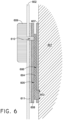
FIG. 6 illustrates a side view example of a physiological parameters telemetry system. -
FIG. 7 illustrates an additional example of a physiological parameters telemetry system. -
FIGS. 8A-C illustrates additional garments incorporated into a physiological parameters telemetry system. - Corresponding reference numerals indicate corresponding parts throughout the several views of the drawings.
- Referring to
FIG. 1A , one example of a user interface component for physiological parameters telemetry is depicted. A user interface component may comprise at least oneconductive transfer layer 102 and asignal receiving unit 105 connected to the at least oneconductive transfer layer 102. Theconductive transfer layer 102 may have atop side 104 and abottom side 103. Generally, at least a portion of thebottom side 103 of the at least oneconductive transfer layer 102 contacts a user'sskin 101. Thermal and/or electrical signals may propagate through the at least oneconductive transfer layer 102 and be received by thesignal receiving unit 105.FIG. 1B illustrates one example of auser interface component 106. The "inverted-T" shape of theuser interface component 106 is merely exemplary. Additional shapes of the user interface component and conductive transfer layers may be employed for various locations of a user's body or to accommodate measurement of varying physiological data. Thesignal receiving unit 105 transmits the collected physiological parameters data to one or more external recording or computing sources. Thesignal receiving unit 105 may transmit signals in any form using any useful data transfer formats or protocols. For example, signals may be relayed to external sources by radio transmissions and/or cellular telephone transmissions. Signals may utilize 802.11 protocols, Bluetooth, etc. In one example, thesignal receiving unit 105 is connected to a portion of the user interface component. Thesignal receiving unit 105 may also store data for later downloading or transmission through either a wireless or wired connection. Furthermore, thesignal receiving unit 105 may be removable so that the user interface component may be launderable without compromising electronics within thesignal receiving unit 105. - One example of a conductive transfer layer may use a silver or silver impregnated substrate to provide conductivity of electric and/or thermal signals. In another example, carbon is used as the conductive material. Alternately or in conjunction, a conducting polymer or other organic material is employed as a conductive portion of the conductive transfer layer. For example, electrically conductive fabric or fibers may be incorporated into a conductive transfer layer. It may be advantageous to include a plurality of materials in order to transmit different physiological signals.
-
FIG. 2 illustrates one example of a user interface component incorporated into a system for physiological parameters telemetry. A system for physiological parameters telemetry may include ashirt 200 or other garment or accessory worn such that at least a portion touches the user's skin. A compressive shirt or other compressive garment may be incorporated into a system for physiological parameters telemetry to assure sufficient contact with the user's skin to make measurements. In another example, the system may be incorporated into a belt or sport bra. The example of theshirt 200 includes one ormore holes conductive transfer layer 205 to contact the user's skin. Theholes FIG. 2 are not necessarily to scale with theshirt 200. The holes may be of varying size and location to accommodate the user interface component. For example, one or more holes for contact may be in the chest area of a garment and/or the armpit areas of a garment and/or back areas. For some applications, a micro-scale user interface component may be employed, and the contact area to the user's skin provided by the holes may be scaled accordingly. In another example, the garment itself may use conductive portions to bridge between the user's skin and the user interface component so that direct contact of the user's skin with the user interface component is minimized. - Returning to
FIG. 2 , a portion of the conductive transfer layer contacts the user's skin throughholes garment 200. Another portion of theconductive transfer layer signal receiving unit 207. Thesignal receiving unit 207 receives thermal and electrical signals collected from the user through the conductive transfer layer and relays them to various external data collection and analysis units. The user interface component may be removable from thegarment 200 and may include a plurality of materials to provide one or more conductive transfer layers. The user interface component may be stitched, bonded, or adhered to the garment to provide stability while being worn by the user. Thesignal receiving unit 207 may also be separated from the system. The signal receiving unit may be held in place by any means, including stitching, bonding, apparel closures such as snaps or hook-and-eye closures, or using magnetic closures. - Examples of electronic modules that may be incorporated into the signal receiving unit or the sensor are illustrated in
U.S. patent application Ser. No. 11/416,458 , published asU.S. Patent Application Publication No. 2007/0260421 , the entirety of which is incorporated by reference herein and made part of hereof. Aspects of the invention may relate toU.S. Patent Application Ser. No. 11/166,351 , published asU.S. Patent Application 2007/0011919 , and alsoU.S. Patent Application Ser. No. 11/848,988 , patented asU.S. Patent No. 7,771,320 , both of which are incorporated by reference herein and made part of hereof. -
FIG. 3 illustrates an additional example of user interface component and system for physiological parameters telemetry. Theuser interface component 301 may comprise aconductive transfer layer 303. Theconductive transfer layer 303 may be an electrically conductive heat transfer layer. Theconductive transfer layer 303 contacts a portion of the user's skin through one ormore holes garment 300. Theconductive transfer layer 303 also contacts at least onesignal receiving units 302. Additionally, theuser interface component 301 may include a bottom insulatinglayer 306 contacting theconductive transfer layer 303 on the bottom side and isolating or insulating a portion of the bottom side of theconductive transfer layer 303 from thegarment 302. The bottom insulatinglayer 306 also provides an exposedregion 307 for the conductive transfer layer to line up with theholes garment 300 for contacting the user's skin. - The
user interface component 301 may also have a top insulatinglayer 308 contacting the top side of theconductive transfer layer 303. The top insulatinglayer 308 may protect theconductive transfer layer 303 from environmental contamination and/or damage. The top insulatinglayer 308 may also have a point ofcontact 309 to expose theconductive transfer layer 303 and allow thesignal receiving unit 302 to connect with theconductive transfer layer 303. The top insulatinglayer 308 may possess decorative elements. While the top insulatinglayer 308, theconductive transfer layer 303, and the bottom insulatinglayer 306 are illustrated as three separate layers, a plurality of layers may be used for any individual layer. In addition, the top insulatinglayer 308 and the bottom insulatinglayer 306 may be formed of one material and encapsulate theconductive transfer layer 303. - There may also be provided an
adhesive layer 310 on either the garment or on the garment facing side of the bottom insulatinglayer 306 or directly on theconductive transfer layer 303. Theadhesive layer 310 and the bottom insulatinglayer 306 may be the same layer. Theadhesive layer 310 may be provided to any portion of theuser interface component 301. Theadhesive layer 310 may have glue or other bonding medium to provide robust attachment of theuser interface component 301 to thegarment 300. Theadhesive layer 310 may have a reversible or irreversible attachment mechanism. Alternately or in conjunction, conventional apparel fasteners, such as hook-and-eye closures, buttons, or snaps, may be employed to attach theuser interface component 301 to thegarment 300. -
FIG. 4 illustrates a side view of one example of a system for physiological parameters telemetry. Generally, the user interface component may comprise aconductive transfer layer 404 having atop side 405 and abottom side 406. A portion of thebottom side 406 may contact the user'sskin 401. InFIG. 4 , a user'sskin 401 is illustrated with a fabric orother garment layer 402. The fabric orother garment layer 402 may lie substantially between the user interface component and the user'sskin 401. However, the garment orfabric 402 may include at least one hole so that aportion 403 of theconductive transfer layer 404 may contact the user's skin. WhileFIG. 4 shows direct contact between theconductive transfer layer 404 and the user'sskin 401, there may be additional intervening conductive materials or layers. For example, a conductive adhesive or lubricant may be applied to the conductive transfer layer or the user's skin. In another example, the hole in thegarment 402 may be supplemented with a conductive polymer impregnated into the fabric so that direct contact of the user's skin can be avoided. The garment itself may be wholly or partially constructed of a thermal and/or electrically conductive material, in which case, the user interface component may be connected with the user skin via the bridge provided by the conductive garment. The system inFIG. 4 may further comprise asignal receiving unit 409 thatcontacts 410 theconductive transfer layer 404. - The
garment 402 may have a back side against the user's skin and a face side away from the user's skin. Thegarment 402 worn by the user with at least onehole 403 provided such that theconductive transfer layer 404 contacts a portion of the user'sskin 401. In one example, the garment may be a compressive shirt and one or more holes may be in the chest area of the compressive shirt. The conductive transfer layer may have abottom side 406 and atop side 405. The bottom side of theconductive transfer layer 406 may contact the user's skin. The bottom insulatinglayer 407 may contact at least a portion of thebottom side 406 of theconductive transfer layer 404. The bottom insulatinglayer 407 may protect thebottom side 406 of theconductive transfer layer 404 from the user's body and environment. Theadhesive layer 411 may allow robust attachment of the bottom insulatinglayer 407 to the face side of thegarment 402. Theadhesive layer 411 may cover all or a portion of the bottom insulatinglayer 407. Theadhesive layer 411 may also be applied to theconductive transfer layer 404 while leaving aportion 403 of theconductive transfer layer 404 exposed to allow contact with the user'sskin 401. At least a portion of theconductive transfer layer 404 may be exposed by the bottom insulating layer to allow contact with the user'sskin 401. - The top insulating
layer 408 contacts a portion of thetop side 405 ofconductive transfer layer 404 and may provide protection for theconductive transfer layer 404 from the user's environment. The top insulatinglayer 408 may include a region where thetop side 405 of theconductive transfer layer 404 is partially exposed to provide at least onecontact point 410 for at least onesignal receiving unit 409. While it is illustrated that each layer is in direct contact, the layers may include intervening sublayers and/or other components to bridge the connections or provide other functionality. -
FIG. 5 illustrates one example of a system for physiological parameters telemetry. Thegarment 500 may be a shirt as illustrated but may be any garment or accessory worn in close fit with the user's skin. One or moreuser interface components 501 may be appliqued to the surface of thegarment 500. As illustrated, theuser interface component 501 is not to scale with the garment. Theuser interface component 501 may have any size ratio in comparison with the garment, which is particularly advantageous as the dimensions of theuser interface component 501 may be determined by the physiological parameters to be collected. InFIG. 5 , theuser interface component 501 is located in achest area 503 of thegarment 500 and theholes chest area 503. While it is illustrated that a user interface component is located in a chest area, the user interface component may be located anywhere on the garment. For example, it may be useful to include user interface component(s) at the armpit and/or back regions. While it is illustrated that there is one user interface component to one signal receiving unit, any ratio of user interface components to signal receiving units may be utilized in a system for physiological parameters telemetry. For example, it may be useful to have multiple user interface components connected to a single signal receiving unit. Alternately or in conjunction, a single user interface component may transmit a plurality of signals to a plurality of signal receiving units. -
FIG. 6 illustrates an additional example of a system for physiological parameters telemetry in which the user interface component lies next to the user's skin such as on the inside of a garment, such as a compressive shirt or other form-fitting apparel. The user interface component may be bonded, stitched, or appliquéd to the back side of a garment. Another example might include a system in which the user interface component is embedded within the shirt. Generally, the user interface component may comprise aconductive transfer layer 604 having atop side 605 and abottom side 606. A portion of thebottom side 606 may contact the user'sskin 601. InFIG. 6 , a fabric orother garment layer 602 illustrated with a user interface component that lies substantially between the fabric orother garment layer 602 and the user'sskin 601. WhileFIG. 6 shows direct contact between theconductive transfer layer 604 and the user'sskin 601, there may be additional intervening conductive materials or layers. For example, a conductive adhesive or lubricant may be applied to the conductive transfer layer or the user's skin. The system inFIG. 6 may further comprise asignal receiving unit 609 thatcontacts 610 theconductive transfer layer 604. - The
garment 602 may have a back side against the user's skin and a face side away from the user's skin. The user interface component may be applied against the user's skin and attached to the back side of thegarment 602. In one example, the garment may be a compressive shirt and one or more holes may be in the chest area of the compressive shirt. The conductive transfer layer may have abottom side 606 and atop side 605. The bottom side of theconductive transfer layer 606 may contact the user's skin. The bottom insulatinglayer 607 may contact at least a portion of thebottom side 606 of theconductive transfer layer 604. The bottom insulatinglayer 607 may protect thebottom side 606 of theconductive transfer layer 604 from the user's body - The top insulating
layer 608 contacts a portion of thetop side 605 ofconductive transfer layer 604 and may lie substantially between theconductive transfer layer 604 andgarment 602 or the back side of the garment. The top insulatinglayer 608 may include a region where thetop side 605 of theconductive transfer layer 604 is partially exposed to provide at least onecontact point 610 for at least onesignal receiving unit 609. Contact through the face side and the back side of the garment to the user interface component may be provided by small holes or other conductive bridging materials. While it is illustrated that each layer is in direct contact, the layers may include intervening sublayers and/or other components to bridge the connections or provide other functionality - The
adhesive layer 611 may allow robust attachment of the top insulatinglayer 608 to the back side of thegarment 402. Theadhesive layer 611 may cover all or a portion of the top insulatinglayer 608. Theadhesive layer 611 may also be applied to theconductive transfer layer 604 to adhere the conductive transfer layer to the back side of the garment. At least aportion 603 of theconductive transfer layer 604 may be exposed by the top insulatinglayer 608 to allow contact with the signal receiving unit. -
FIG. 7 illustrates an additional example of user interface component and system for physiological parameters telemetry. Theuser interface component 701 may comprise aconductive transfer layer 703. Theconductive transfer layer 703 may be an electrically conductive heat transfer layer. Theconductive transfer layer 703 contacts a portion of the user's skin and lies substantially between the garment and the user's skin. Theconductive transfer layer 703 also contacts at least onesignal receiving units 702. Additionally, theuser interface component 701 may include a bottom insulatinglayer 706 contacting theconductive transfer layer 703 on the bottom side and isolating or insulating a portion of the bottom side of theconductive transfer layer 703 from the user's skin. The bottom insulatinglayer 706 also provides an exposedregion 707 for contacting the user's skin. - The
user interface component 701 may also have a top insulatinglayer 708 contacting the top side of theconductive transfer layer 703. The top insulatinglayer 701 may lie substantially between the garment or fabric and theconductive transfer layer 703. The top insulatinglayer 708 may also have a point ofcontact 709 to expose theconductive transfer layer 703 and allow thesignal receiving unit 702 to connect with theconductive transfer layer 703. While the top insulatinglayer 708, theconductive transfer layer 703, and the bottom insulatinglayer 706 are illustrated as three separate layers, a plurality of layers may be used for any individual layer. In addition, the top insulatinglayer 708 and the bottom insulatinglayer 706 may be formed of one material and encapsulate theconductive transfer layer 703. - There may also be provided an
adhesive layer 710 on either the garment or on the garment facing side of the top insulatinglayer 708 or directly on the top side of theconductive transfer layer 703. Theadhesive layer 710 and the top insulatinglayer 708 may be the same layer. Theadhesive layer 710 may be provided to any portion of theuser interface component 701. Theadhesive layer 710 may have glue or other bonding medium to provide robust attachment of theuser interface component 701 to thegarment 700. Theadhesive layer 710 may have a reversible or irreversible attachment mechanism. Alternately or in conjunction, conventional apparel fasteners, such as hook-and-eye closures, buttons, or snaps, may be employed to attach theuser interface component 701 to thegarment 700. -
FIGS. 8A-C illustrates additional examples of garments that are incorporated with a system for physiological parameters telemetry.FIG. 8A illustrates auser interface component 801 and signal receiving unit may be attached to abelt 802.FIG. 8B illustrates a user interface component andsignal receiving unit 803 may be attached to a sport bra.FIG. 8C illustratesuser interface components shorts 803, particularly close-fitting bottoms such as undergarments or compressive shorts. The general locations illustrated inFIG. 8A-C are merely exemplary and further are not to scale. Locations for user interface components may vary according to the user and the physiological parameters to be monitors. A plurality of user interface components may be applied to areas of several garments to achieve comprehensive physiological telemetry. - A variety of physiological data may be obtained and transmitted by the described systems. Non-limiting examples of physiological parameters that may be monitored include: skin temperature, perspiration rate and for content, heart rate, blood pressure, heat flux, muscle contraction, etc. For example, skin temperature and/or core body temperature of an athlete at various levels of exertion and in different environments may be monitored. An athlete's pulse rate and/or blood pressure may be tracked as well. Respiratory rate statistics may be collected. Electrolyte loss via sweat may be monitored. Measurement and collection of different physiological data may include locating one or more user interface components at different areas of an athlete's body. For example, pulse rate may be measured near the carotid artery, the wrist, behind the knee or on the chest. In addition, the material and construction of the user interface component may be adjusted for the type of data to be collected. In an additional example, the user interface component may provide a conductive connection between the signal receiving unit and an additional unit connected with the user's skin. For additional sensing applications, it may be useful to provide a small current from the signal receiving unit having a power source to the user interface component.
- The foregoing description of the embodiments has been provided for purposes of illustration and description. It is not intended to be exhaustive or to limit the invention. Individual elements or features of a particular embodiment are generally not limited to that particular embodiment, but, where applicable, are interchangeable and may be used in a selected embodiment, even if not specifically shown or described.
- Preferred features of the invention are defined in the following clauses:
- 1. A system for physiological parameters telemetry, the system comprising: at least one user interface component comprising at least one conductive transfer layer having a bottom side and a top side, at least a portion of the bottom side is adapted to contact a user's skin; at least one signal receiving unit connected to the top side of the at least one conductive transfer layer; and a garment having a back side contacting the user's skin and a face side and adapted to receive the at least one signal receiving unit at the face side and adapted to receive the at least one user interface component on at least one of the face side or the back side.
- 2. The system of clause 1, the garment comprising one or more holes exposing the user's skin such that the portion of the bottom side of the at least one user interface component contacts the user's skin at the one or more holes.
- 3. The system of clause 1, wherein the top side of the user interface component is on the back side of the garment.
- 4. The system of clause 2, the at least one user interface component further comprising a bottom insulating layer contacting the bottom side and isolating at least a portion of the bottom side of the at least one conductive transfer layer from face side of the garment.
- 5. The system of clause 1, the at least one user interface component further comprising a top insulating layer contacting the top side of the at least one conductive transfer layer.
- 6. The system of clause 4, the at least one user interface component further comprising an adhesive layer at least in part between the bottom insulating layer and the face side of the garment.
- 7. The system of clause 2, wherein the garment is a shirt and the one or more holes is located at a chest area of the shirt.
- 8. The system of clause 1, the at least one conductive transfer layer is an electrically conductive heat transfer layer.
- 9. A user interface component for physiological parameters telemetry worn on a garment, the component comprising: at least one conductive transfer layer having a bottom side and a top side, at least a portion of the bottom side is adapted to contact a user's skin through one or more holes in a garment, the garment having a face side and a back side; a bottom insulating layer contacting the bottom side and isolating at least a portion of the bottom side of the at least one conductive transfer layer from the face side of the garment; and a top insulating layer contacting the top side of the at least one conductive transfer layer.
- 10. The user interface component of clause 9, further comprising an adhesive layer at least in part between the bottom insulating layer and the face side of the garment.
- 11. The user interface component of clause 9, wherein the bottom insulating layer is bonded to the face side of the garment.
- 12. The user interface component of clause 9, the at least one conductive transfer layer is an electrically conductive heat transfer layer.
- 13. The user interface component of clause 9, the at least one conductive transfer layer comprises a metal.
- 14. The user interface component of clause 9, the at least one conductive transfer layer comprises a carbon material.
- 15. The user interface component of clause 9, wherein the garment is a shirt and the one or more holes are located at a chest area of the shirt.
- 16. A user interface component for physiological parameters telemetry worn on a garment, the component comprising: at least one conductive transfer layer having a bottom side and a top side, at least a portion of the bottom side is adapted to contact a user's skin when attached to a garment worn by the user, the garment having a face side and a back side; a bottom insulating layer contacting the bottom side and isolating at least a portion of the bottom side of the at least one conductive transfer layer; and a top insulating layer contacting the top side of the at least one conductive transfer layer.
Claims (6)
- A system for physiological parameters telemetry, the system comprising:at least one user interface component comprising at least one conductive transfer layer having a bottom side and a top side, at least a portion of the bottom side is adapted to contact a user's skin;at least one signal receiving unit removably connected to the top side of the at least one conductive transfer layer; anda garment having a back side contacting the user's skin and a face side and adapted to receive the at least one signal receiving unit at the face side and adapted to receive the at least one user interface component on at least one of the face side or the back side, whereinthe at least one user interface component comprises a bottom insulating layer contacting the bottom side and isolating at least a portion of the bottom side of the at least one conductive transfer layer from face side of the garment; and/or further comprises a top insulating layer contacting the top side of the at least one conductive transfer layer.
- The system of claim 1, the garment comprising one or more holes exposing the user's skin such that the portion of the bottom side of the at least one user interface component contacts the user's skin at the one or more holes.
- The system of claim 1, wherein the top side of the user interface component is on the back side of the garment.
- The system of claim 1, wherein the at least one user interface component further comprising an adhesive layer at least in part between the bottom insulating layer and the face side of the garment.
- The system of claim 2, wherein the garment is a shirt and the one or more holes is located at a chest area of the shirt.
- The system of claim 1, the at least one conductive transfer layer is an electrically conductive heat transfer layer.
Applications Claiming Priority (4)
| Application Number | Priority Date | Filing Date | Title |
|---|---|---|---|
| US13/051,770 US8909318B2 (en) | 2011-03-18 | 2011-03-18 | Apparel for physiological telemetry during athletics |
| PCT/US2012/029448 WO2012129093A2 (en) | 2011-03-18 | 2012-03-16 | Apparel for physiological telemetry during athletics |
| EP17170172.5A EP3228248B1 (en) | 2011-03-18 | 2012-03-16 | Apparel for physiological telemetry during ahtletics |
| EP12761274.5A EP2685893A4 (en) | 2011-03-18 | 2012-03-16 | Apparel for physiological telemetry during athletics |
Related Parent Applications (2)
| Application Number | Title | Priority Date | Filing Date |
|---|---|---|---|
| EP12761274.5A Division EP2685893A4 (en) | 2011-03-18 | 2012-03-16 | Apparel for physiological telemetry during athletics |
| EP17170172.5A Division EP3228248B1 (en) | 2011-03-18 | 2012-03-16 | Apparel for physiological telemetry during ahtletics |
Publications (2)
| Publication Number | Publication Date |
|---|---|
| EP4417116A2 true EP4417116A2 (en) | 2024-08-21 |
| EP4417116A3 EP4417116A3 (en) | 2024-11-13 |
Family
ID=46829017
Family Applications (3)
| Application Number | Title | Priority Date | Filing Date |
|---|---|---|---|
| EP17170172.5A Active EP3228248B1 (en) | 2011-03-18 | 2012-03-16 | Apparel for physiological telemetry during ahtletics |
| EP12761274.5A Withdrawn EP2685893A4 (en) | 2011-03-18 | 2012-03-16 | Apparel for physiological telemetry during athletics |
| EP24178055.0A Pending EP4417116A3 (en) | 2011-03-18 | 2012-03-16 | Apparel for physiological telemetry during ahtletics |
Family Applications Before (2)
| Application Number | Title | Priority Date | Filing Date |
|---|---|---|---|
| EP17170172.5A Active EP3228248B1 (en) | 2011-03-18 | 2012-03-16 | Apparel for physiological telemetry during ahtletics |
| EP12761274.5A Withdrawn EP2685893A4 (en) | 2011-03-18 | 2012-03-16 | Apparel for physiological telemetry during athletics |
Country Status (4)
| Country | Link |
|---|---|
| US (2) | US8909318B2 (en) |
| EP (3) | EP3228248B1 (en) |
| CN (1) | CN103764020B (en) |
| WO (1) | WO2012129093A2 (en) |
Families Citing this family (78)
| Publication number | Priority date | Publication date | Assignee | Title |
|---|---|---|---|---|
| US20120172940A1 (en) * | 2010-11-30 | 2012-07-05 | Wahls Terry L | Therapeutic Garment |
| US9775561B2 (en) * | 2010-12-23 | 2017-10-03 | Covidien Lp | System method and device for monitoring physiological parameters of a person |
| US20130212768A1 (en) * | 2012-02-21 | 2013-08-22 | Timothy C. Robinson | Modular Detoxification Garment |
| DE102012206062B4 (en) | 2012-04-13 | 2019-09-12 | Adidas Ag | SHOE UPPER PART |
| US9498128B2 (en) | 2012-11-14 | 2016-11-22 | MAD Apparel, Inc. | Wearable architecture and methods for performance monitoring, analysis, and feedback |
| US9402429B2 (en) * | 2013-03-14 | 2016-08-02 | Nike, Inc. | Telemetrically enhanced athletic apparel |
| DE102013207156B4 (en) | 2013-04-19 | 2025-12-24 | Adidas Ag | shoe, especially a sports shoe |
| US12250994B2 (en) | 2013-04-19 | 2025-03-18 | Adidas Ag | Shoe |
| DE102013207163B4 (en) | 2013-04-19 | 2022-09-22 | Adidas Ag | shoe upper |
| DE102013207155B4 (en) | 2013-04-19 | 2020-04-23 | Adidas Ag | Shoe upper |
| US11666113B2 (en) | 2013-04-19 | 2023-06-06 | Adidas Ag | Shoe with knitted outer sole |
| KR101449471B1 (en) * | 2013-07-02 | 2014-10-13 | 한국생산기술연구원 | Connecting structure and method of fabric sensor and digital yarn |
| US20150033437A1 (en) * | 2013-08-02 | 2015-02-05 | Douglas D. Hampton | Temperature Adjustable Air-Cooled Undergarment |
| US10624551B2 (en) | 2013-09-25 | 2020-04-21 | Bardy Diagnostics, Inc. | Insertable cardiac monitor for use in performing long term electrocardiographic monitoring |
| US9717433B2 (en) | 2013-09-25 | 2017-08-01 | Bardy Diagnostics, Inc. | Ambulatory electrocardiography monitoring patch optimized for capturing low amplitude cardiac action potential propagation |
| US10806360B2 (en) | 2013-09-25 | 2020-10-20 | Bardy Diagnostics, Inc. | Extended wear ambulatory electrocardiography and physiological sensor monitor |
| US9655538B2 (en) | 2013-09-25 | 2017-05-23 | Bardy Diagnostics, Inc. | Self-authenticating electrocardiography monitoring circuit |
| US10667711B1 (en) | 2013-09-25 | 2020-06-02 | Bardy Diagnostics, Inc. | Contact-activated extended wear electrocardiography and physiological sensor monitor recorder |
| US11213237B2 (en) | 2013-09-25 | 2022-01-04 | Bardy Diagnostics, Inc. | System and method for secure cloud-based physiological data processing and delivery |
| US10165946B2 (en) | 2013-09-25 | 2019-01-01 | Bardy Diagnostics, Inc. | Computer-implemented system and method for providing a personal mobile device-triggered medical intervention |
| US10736531B2 (en) | 2013-09-25 | 2020-08-11 | Bardy Diagnostics, Inc. | Subcutaneous insertable cardiac monitor optimized for long term, low amplitude electrocardiographic data collection |
| US9504423B1 (en) | 2015-10-05 | 2016-11-29 | Bardy Diagnostics, Inc. | Method for addressing medical conditions through a wearable health monitor with the aid of a digital computer |
| US9775536B2 (en) | 2013-09-25 | 2017-10-03 | Bardy Diagnostics, Inc. | Method for constructing a stress-pliant physiological electrode assembly |
| US9655537B2 (en) | 2013-09-25 | 2017-05-23 | Bardy Diagnostics, Inc. | Wearable electrocardiography and physiology monitoring ensemble |
| US9615763B2 (en) | 2013-09-25 | 2017-04-11 | Bardy Diagnostics, Inc. | Ambulatory electrocardiography monitor recorder optimized for capturing low amplitude cardiac action potential propagation |
| US20190167139A1 (en) | 2017-12-05 | 2019-06-06 | Gust H. Bardy | Subcutaneous P-Wave Centric Insertable Cardiac Monitor For Long Term Electrocardiographic Monitoring |
| US10888239B2 (en) | 2013-09-25 | 2021-01-12 | Bardy Diagnostics, Inc. | Remote interfacing electrocardiography patch |
| US9700227B2 (en) | 2013-09-25 | 2017-07-11 | Bardy Diagnostics, Inc. | Ambulatory electrocardiography monitoring patch optimized for capturing low amplitude cardiac action potential propagation |
| US9364155B2 (en) | 2013-09-25 | 2016-06-14 | Bardy Diagnostics, Inc. | Self-contained personal air flow sensing monitor |
| US9619660B1 (en) | 2013-09-25 | 2017-04-11 | Bardy Diagnostics, Inc. | Computer-implemented system for secure physiological data collection and processing |
| US10820801B2 (en) | 2013-09-25 | 2020-11-03 | Bardy Diagnostics, Inc. | Electrocardiography monitor configured for self-optimizing ECG data compression |
| US10736529B2 (en) | 2013-09-25 | 2020-08-11 | Bardy Diagnostics, Inc. | Subcutaneous insertable electrocardiography monitor |
| US10433748B2 (en) | 2013-09-25 | 2019-10-08 | Bardy Diagnostics, Inc. | Extended wear electrocardiography and physiological sensor monitor |
| US9545204B2 (en) | 2013-09-25 | 2017-01-17 | Bardy Diagnostics, Inc. | Extended wear electrocardiography patch |
| US11723575B2 (en) | 2013-09-25 | 2023-08-15 | Bardy Diagnostics, Inc. | Electrocardiography patch |
| US9433367B2 (en) | 2013-09-25 | 2016-09-06 | Bardy Diagnostics, Inc. | Remote interfacing of extended wear electrocardiography and physiological sensor monitor |
| US9408545B2 (en) | 2013-09-25 | 2016-08-09 | Bardy Diagnostics, Inc. | Method for efficiently encoding and compressing ECG data optimized for use in an ambulatory ECG monitor |
| US10463269B2 (en) | 2013-09-25 | 2019-11-05 | Bardy Diagnostics, Inc. | System and method for machine-learning-based atrial fibrillation detection |
| US9737224B2 (en) | 2013-09-25 | 2017-08-22 | Bardy Diagnostics, Inc. | Event alerting through actigraphy embedded within electrocardiographic data |
| US9408551B2 (en) | 2013-11-14 | 2016-08-09 | Bardy Diagnostics, Inc. | System and method for facilitating diagnosis of cardiac rhythm disorders with the aid of a digital computer |
| US10799137B2 (en) | 2013-09-25 | 2020-10-13 | Bardy Diagnostics, Inc. | System and method for facilitating a cardiac rhythm disorder diagnosis with the aid of a digital computer |
| US9717432B2 (en) | 2013-09-25 | 2017-08-01 | Bardy Diagnostics, Inc. | Extended wear electrocardiography patch using interlaced wire electrodes |
| US10433751B2 (en) | 2013-09-25 | 2019-10-08 | Bardy Diagnostics, Inc. | System and method for facilitating a cardiac rhythm disorder diagnosis based on subcutaneous cardiac monitoring data |
| US10251576B2 (en) | 2013-09-25 | 2019-04-09 | Bardy Diagnostics, Inc. | System and method for ECG data classification for use in facilitating diagnosis of cardiac rhythm disorders with the aid of a digital computer |
| WO2015048194A1 (en) | 2013-09-25 | 2015-04-02 | Bardy Diagnostics, Inc. | Self-contained personal air flow sensing monitor |
| US9345414B1 (en) | 2013-09-25 | 2016-05-24 | Bardy Diagnostics, Inc. | Method for providing dynamic gain over electrocardiographic data with the aid of a digital computer |
| JP2015083728A (en) * | 2013-10-25 | 2015-04-30 | セイコーインスツル株式会社 | clothing |
| JP6233804B2 (en) * | 2013-10-25 | 2017-11-22 | セイコーインスツル株式会社 | Portable electronic devices |
| US10292652B2 (en) | 2013-11-23 | 2019-05-21 | MAD Apparel, Inc. | System and method for monitoring biometric signals |
| US10321832B2 (en) | 2013-11-23 | 2019-06-18 | MAD Apparel, Inc. | System and method for monitoring biometric signals |
| US11219396B2 (en) | 2013-11-23 | 2022-01-11 | MAD Apparel, Inc. | System and method for monitoring biometric signals |
| DE102014202432B4 (en) | 2014-02-11 | 2017-07-27 | Adidas Ag | Improved football boot |
| US10617354B2 (en) | 2014-04-29 | 2020-04-14 | MAD Apparel, Inc. | Biometric electrode system and method of manufacture |
| US20150359485A1 (en) * | 2014-06-17 | 2015-12-17 | MAD Apparel, Inc. | Biometric signal conduction system and method of manufacture |
| US10398376B2 (en) | 2014-06-17 | 2019-09-03 | MAD Apparel, Inc. | Garment integrated electrical interface system and method of manufacture |
| DE102014220087B4 (en) | 2014-10-02 | 2016-05-12 | Adidas Ag | Flat knitted shoe top for sports shoes |
| US9913611B2 (en) | 2014-11-10 | 2018-03-13 | MAD Apparel, Inc. | Garment integrated sensing system and method |
| TWI531471B (en) * | 2014-11-26 | 2016-05-01 | 金寶電子工業股份有限公司 | Textile structure |
| US10660382B2 (en) * | 2015-02-27 | 2020-05-26 | Honeywell Safety Products Usa, Inc. | Apparatus, systems and methods for optimizing and masking compression in a biosensing garment |
| US20160278702A1 (en) * | 2015-03-23 | 2016-09-29 | Zentan Technology Co., Ltd. | Physiological signal monitoring belt |
| CN105581793A (en) * | 2016-01-29 | 2016-05-18 | 上海傲意信息科技有限公司 | Human body bioelectricity monitoring garment |
| US10426343B2 (en) | 2016-03-17 | 2019-10-01 | Industrial Technology Research Institute | Physiology detecting garment, physiology detecting monitoring system and manufacturing method of textile antenna |
| US10993635B1 (en) * | 2016-03-22 | 2021-05-04 | Flextronics Ap, Llc | Integrating biosensor to compression shirt textile and interconnect method |
| DE102016118001A1 (en) * | 2016-05-25 | 2017-11-30 | Teiimo Gmbh | Textile product with expandable electrode and / or external contact of the electrode or other sensor, and method for its preparation |
| TW201740828A (en) * | 2016-05-30 | 2017-12-01 | 金鼎聯合科技纖維股份有限公司 | Method of sewing a wire |
| WO2018103817A1 (en) | 2016-12-05 | 2018-06-14 | Vexatec Ag | Garment for measuring physiological data |
| WO2018104329A1 (en) | 2016-12-05 | 2018-06-14 | Vexatec Ag | System for measuring physiological data |
| US10881001B2 (en) | 2017-03-02 | 2020-12-29 | Flex Ltd. | Micro conductive thread interconnect component to make an interconnect between conductive threads in fabrics to PCB, FPC, and rigid-flex circuits |
| US10757800B1 (en) | 2017-06-22 | 2020-08-25 | Flex Ltd. | Stripline transmission lines with cross-hatched pattern return plane, where the striplines do not overlap any intersections in the cross-hatched pattern |
| WO2019068902A1 (en) | 2017-10-06 | 2019-04-11 | Vexatec Ag | Garment for measuring physiological data |
| US10690559B1 (en) | 2018-03-28 | 2020-06-23 | Flex Ltd. | Pressure sensor array and the method of making |
| DE202018105121U1 (en) * | 2018-09-07 | 2018-12-17 | Johann Seidl | Carrier system for a training or therapy system |
| US10985484B1 (en) | 2018-10-01 | 2021-04-20 | Flex Ltd. | Electronic conductive interconnection for bridging across irregular areas in a textile product |
| CN109288501A (en) * | 2018-11-27 | 2019-02-01 | 深圳乐测物联网科技有限公司 | A kind of clothing and wearable device |
| US11696681B2 (en) | 2019-07-03 | 2023-07-11 | Bardy Diagnostics Inc. | Configurable hardware platform for physiological monitoring of a living body |
| US11116451B2 (en) | 2019-07-03 | 2021-09-14 | Bardy Diagnostics, Inc. | Subcutaneous P-wave centric insertable cardiac monitor with energy harvesting capabilities |
| US11096579B2 (en) | 2019-07-03 | 2021-08-24 | Bardy Diagnostics, Inc. | System and method for remote ECG data streaming in real-time |
| GB2594335B (en) * | 2020-04-20 | 2022-07-20 | Prevayl Innovations Ltd | Wearable article and method of making the same |
Citations (3)
| Publication number | Priority date | Publication date | Assignee | Title |
|---|---|---|---|---|
| US20070011919A1 (en) | 2005-06-27 | 2007-01-18 | Case Charles W Jr | Systems for activating and/or authenticating electronic devices for operation with footwear and other uses |
| US20070260421A1 (en) | 2006-05-03 | 2007-11-08 | Nike, Inc. | Athletic or other performance sensing systems |
| US7771320B2 (en) | 2006-09-07 | 2010-08-10 | Nike, Inc. | Athletic performance sensing and/or tracking systems and methods |
Family Cites Families (52)
| Publication number | Priority date | Publication date | Assignee | Title |
|---|---|---|---|---|
| JPH0823095B2 (en) | 1989-06-06 | 1996-03-06 | 東レ株式会社 | Reinforcing fiber fabric |
| US5610877A (en) | 1995-01-20 | 1997-03-11 | Adams; Kathy S. | Fabric attachable timepiece |
| IL115674A (en) * | 1995-10-19 | 2000-10-31 | Tapuz Med Tech Ltd | Electrode apron for ECG |
| WO1998047426A1 (en) | 1997-04-21 | 1998-10-29 | Virtual Technologies, Inc. | Goniometer-based body-tracking device and method |
| US6001749A (en) | 1997-07-30 | 1999-12-14 | Milliken & Company | Patterned conductive textiles |
| US20050096513A1 (en) | 1997-11-11 | 2005-05-05 | Irvine Sensors Corporation | Wearable biomonitor with flexible thinned integrated circuit |
| US20090112078A1 (en) | 2007-10-24 | 2009-04-30 | Joseph Akwo Tabe | Embeded advanced force responsive detection platform for monitoring onfield logistics to physiological change |
| NO311317B1 (en) | 1999-04-30 | 2001-11-12 | Thin Film Electronics Asa | Apparatus comprising electronic and / or optoelectronic circuits and method of realizing and / or integrating circuits of this kind in the apparatus |
| US6895261B1 (en) | 2000-07-13 | 2005-05-17 | Thomas R. Palamides | Portable, wireless communication apparatus integrated with garment |
| US6571115B2 (en) * | 2000-12-26 | 2003-05-27 | Axelgaard Manufacturing Company, Ltd. | Compress garment facilitating the use of medical electrodes |
| FI110915B (en) | 2001-02-19 | 2003-04-30 | Polar Electro Oy | Sensor placed on the skin |
| US6453186B1 (en) * | 2001-04-13 | 2002-09-17 | Ge Medical Systems Information Technologies, Inc. | Electrocardiogram electrode patch |
| CN1283371C (en) * | 2001-06-19 | 2006-11-08 | 奥尔约恩有限责任公司 | UV curable inks for PTF lamination (including flex circuits) |
| US6686038B2 (en) | 2002-02-25 | 2004-02-03 | Koninklijke Philips Electronics N.V. | Conductive fiber |
| US6668380B2 (en) | 2002-02-28 | 2003-12-30 | Koninklijke Philips Electronics N.V. | Selectively detachable and wearable electrode/sensors |
| US20040009731A1 (en) * | 2002-07-11 | 2004-01-15 | Tefron | Garment with discrete integrally-formed, electrically-conductive region and associated blank and method |
| US20040051082A1 (en) | 2002-09-16 | 2004-03-18 | Child Andrew D. | Static dissipative textile and method for producing the same |
| US7320947B2 (en) | 2002-09-16 | 2008-01-22 | Milliken & Company | Static dissipative textile and method for producing the same |
| GB0230361D0 (en) | 2002-12-27 | 2003-02-05 | Koninkl Philips Electronics Nv | Electrode arrangement |
| US20050095406A1 (en) | 2003-10-31 | 2005-05-05 | Gunzel Edward C. | Attachment of cables to flexible fabrics |
| DE102004004852A1 (en) | 2004-01-30 | 2005-08-18 | Falke Kg | garment |
| WO2005089645A1 (en) | 2004-03-24 | 2005-09-29 | Dainippon Sumitomo Pharma Co., Ltd. | Biological information measuring garment having sensor, biological information measuring system and equipment, and control method of equipment |
| KR100592934B1 (en) * | 2004-05-21 | 2006-06-23 | 한국전자통신연구원 | Wearable biosignal detection module and measuring device including the same |
| US7120936B2 (en) | 2004-06-17 | 2006-10-17 | Hassler Consortium, Inc. | Watch cuff |
| DE102004030261A1 (en) | 2004-06-23 | 2006-01-19 | Deutsche Institute für Textil- und Faserforschung (DITF) | Garment with integrated sensors |
| US7124447B2 (en) | 2004-06-29 | 2006-10-24 | Arganese Thomas J | Watch head removably attachable to glove |
| US20070299325A1 (en) | 2004-08-20 | 2007-12-27 | Brian Farrell | Physiological status monitoring system |
| DE102004047650B3 (en) | 2004-09-30 | 2006-04-13 | W.L. Gore & Associates Gmbh | Garment with inductive coupler and inductive garment interface |
| US7793361B2 (en) | 2004-11-12 | 2010-09-14 | Nike, Inc. | Article of apparel incorporating a separable electronic device |
| ITFI20040264A1 (en) | 2004-12-14 | 2005-03-14 | Rossi Danilo Emilio De | DEVICES FOR THE MONITORING OF FORMS OF THREE-DIMENSIONAL OBJECTS, FIELDS OF DEFORMATION OF FLEXIBLE SUBSTRATES (ELASTIC AND NOT) AND THEIR REALIZATION WITH INTEGRATED SENSORIZATION |
| FI20045503L (en) | 2004-12-28 | 2006-06-29 | Polar Electro Oy | Sensor system, accessory and heart rate monitor |
| US20060196093A1 (en) | 2005-03-02 | 2006-09-07 | Sneaker Luxe Llc | Detachable bezel for footwear and the like |
| US20060211937A1 (en) * | 2005-03-17 | 2006-09-21 | Robert Eldridge | Garment to facilitate use of a portable monitor device |
| KR100734986B1 (en) * | 2005-09-23 | 2007-07-06 | 한국전자통신연구원 | Bio signal garment |
| KR100759948B1 (en) * | 2005-12-08 | 2007-09-19 | 한국전자통신연구원 | Garment apparatus for measuring physiological signal |
| DE102006004946B4 (en) | 2005-12-08 | 2010-04-29 | BLüCHER GMBH | Functional item of clothing, in particular ABC protective clothing, with integrated measuring device |
| US7306403B1 (en) | 2006-04-19 | 2007-12-11 | Sanders William M | Heated underwater diving suit |
| US8188868B2 (en) | 2006-04-20 | 2012-05-29 | Nike, Inc. | Systems for activating and/or authenticating electronic devices for operation with apparel |
| FI120482B (en) * | 2006-06-08 | 2009-11-13 | Suunto Oy | The sensor arrangement |
| EP2040616B1 (en) | 2006-07-05 | 2012-10-03 | Philips Intellectual Property & Standards GmbH | Wearable blood pressure monitoring system |
| US7684755B2 (en) | 2006-08-29 | 2010-03-23 | Motorola, Inc. | Garment for controlling an electronic device |
| US20080256691A1 (en) | 2007-04-22 | 2008-10-23 | Jackson Wells White | Article of clothing |
| US8560044B2 (en) | 2007-05-16 | 2013-10-15 | Medicomp, Inc. | Garment accessory with electrocardiogram sensors |
| KR100895300B1 (en) * | 2007-07-20 | 2009-05-07 | 한국전자통신연구원 | Biosignal garments and biosignal processing systems |
| KR100863064B1 (en) | 2007-08-03 | 2008-10-13 | 한국전자통신연구원 | Clothing for measuring bio-signals and its manufacturing method |
| EP2178408A2 (en) | 2007-08-15 | 2010-04-28 | Cupid Foundations, Inc. | Garments having a curable polymer thereon and a system and method for its manufacture |
| US8133826B2 (en) | 2007-08-21 | 2012-03-13 | Ut-Battelle, Llc | Thermal control structure and garment |
| US20090088652A1 (en) * | 2007-09-28 | 2009-04-02 | Kathleen Tremblay | Physiological sensor placement and signal transmission device |
| US20090227857A1 (en) | 2008-03-06 | 2009-09-10 | Chuck Rowe | Biomedical electrode |
| US20100077528A1 (en) | 2008-05-12 | 2010-04-01 | Howard Lind | Clothing and apparel integrated with flexible silicone encased cable systems |
| DE102008051536A1 (en) * | 2008-10-14 | 2010-04-15 | Cairos Technologies Ag | Garment for monitoring physiological properties |
| US9775561B2 (en) * | 2010-12-23 | 2017-10-03 | Covidien Lp | System method and device for monitoring physiological parameters of a person |
-
2011
- 2011-03-18 US US13/051,770 patent/US8909318B2/en active Active
-
2012
- 2012-03-16 EP EP17170172.5A patent/EP3228248B1/en active Active
- 2012-03-16 EP EP12761274.5A patent/EP2685893A4/en not_active Withdrawn
- 2012-03-16 CN CN201280014081.XA patent/CN103764020B/en active Active
- 2012-03-16 EP EP24178055.0A patent/EP4417116A3/en active Pending
- 2012-03-16 WO PCT/US2012/029448 patent/WO2012129093A2/en not_active Ceased
-
2014
- 2014-11-07 US US14/535,958 patent/US9782124B2/en active Active
Patent Citations (3)
| Publication number | Priority date | Publication date | Assignee | Title |
|---|---|---|---|---|
| US20070011919A1 (en) | 2005-06-27 | 2007-01-18 | Case Charles W Jr | Systems for activating and/or authenticating electronic devices for operation with footwear and other uses |
| US20070260421A1 (en) | 2006-05-03 | 2007-11-08 | Nike, Inc. | Athletic or other performance sensing systems |
| US7771320B2 (en) | 2006-09-07 | 2010-08-10 | Nike, Inc. | Athletic performance sensing and/or tracking systems and methods |
Also Published As
| Publication number | Publication date |
|---|---|
| EP2685893A4 (en) | 2014-09-17 |
| EP2685893A2 (en) | 2014-01-22 |
| CN103764020B (en) | 2016-01-20 |
| EP3228248A1 (en) | 2017-10-11 |
| US20120238910A1 (en) | 2012-09-20 |
| WO2012129093A3 (en) | 2013-11-28 |
| US20150065843A1 (en) | 2015-03-05 |
| EP3228248B1 (en) | 2024-06-05 |
| CN103764020A (en) | 2014-04-30 |
| EP4417116A3 (en) | 2024-11-13 |
| US9782124B2 (en) | 2017-10-10 |
| US8909318B2 (en) | 2014-12-09 |
| WO2012129093A2 (en) | 2012-09-27 |
Similar Documents
| Publication | Publication Date | Title |
|---|---|---|
| US9782124B2 (en) | Apparel for physiological telemetry during athletics | |
| US12527371B2 (en) | Wearable items providing physiological, environmental and situational parameter monitoring | |
| US11259580B2 (en) | Health monitoring garment and system | |
| US8886281B2 (en) | Snap and electrode assembly for a heart rate monitor belt | |
| KR100895300B1 (en) | Biosignal garments and biosignal processing systems | |
| US10105098B2 (en) | Garment integrated sensing system and method | |
| EP2803315B1 (en) | Heart activity sensor structure | |
| US9028404B2 (en) | Physiological status monitoring system | |
| US20070299325A1 (en) | Physiological status monitoring system | |
| US7783334B2 (en) | Garment for measuring physiological signal | |
| US9572532B2 (en) | Button sensor | |
| WO2016053731A1 (en) | Electrocardiography device for garments | |
| US9861291B2 (en) | Electrode assembly | |
| AU2019473059B2 (en) | Wearable sensor device | |
| US20130178728A1 (en) | Heart rate monitor having electrostatic discharge protective layer | |
| KR101550410B1 (en) | Digital garment for health care using x-band type | |
| GB2601150A (en) | Electronics module and system | |
| CA3160309C (en) | Wearable sensor device |
Legal Events
| Date | Code | Title | Description |
|---|---|---|---|
| PUAI | Public reference made under article 153(3) epc to a published international application that has entered the european phase |
Free format text: ORIGINAL CODE: 0009012 |
|
| STAA | Information on the status of an ep patent application or granted ep patent |
Free format text: STATUS: THE APPLICATION HAS BEEN PUBLISHED |
|
| AC | Divisional application: reference to earlier application |
Ref document number: 2685893 Country of ref document: EP Kind code of ref document: P Ref document number: 3228248 Country of ref document: EP Kind code of ref document: P |
|
| AK | Designated contracting states |
Kind code of ref document: A2 Designated state(s): AL AT BE BG CH CY CZ DE DK EE ES FI FR GB GR HR HU IE IS IT LI LT LU LV MC MK MT NL NO PL PT RO RS SE SI SK SM TR |
|
| REG | Reference to a national code |
Ref country code: DE Ref legal event code: R079 Free format text: PREVIOUS MAIN CLASS: A61B0005024500 Ipc: A41D0013000000 |
|
| PUAL | Search report despatched |
Free format text: ORIGINAL CODE: 0009013 |
|
| AK | Designated contracting states |
Kind code of ref document: A3 Designated state(s): AL AT BE BG CH CY CZ DE DK EE ES FI FR GB GR HR HU IE IS IT LI LT LU LV MC MK MT NL NO PL PT RO RS SE SI SK SM TR |
|
| RIC1 | Information provided on ipc code assigned before grant |
Ipc: A61B 5/103 20060101ALI20241004BHEP Ipc: A61B 5/0245 20060101ALI20241004BHEP Ipc: A61B 5/024 20060101ALI20241004BHEP Ipc: A61B 5/00 20060101ALI20241004BHEP Ipc: A41D 13/12 20060101ALI20241004BHEP Ipc: A41D 13/00 20060101AFI20241004BHEP |
|
| STAA | Information on the status of an ep patent application or granted ep patent |
Free format text: STATUS: REQUEST FOR EXAMINATION WAS MADE |
|
| 17P | Request for examination filed |
Effective date: 20250507 |
|
| P01 | Opt-out of the competence of the unified patent court (upc) registered |
Free format text: CASE NUMBER: APP_24993/2025 Effective date: 20250526 |
|
| STAA | Information on the status of an ep patent application or granted ep patent |
Free format text: STATUS: EXAMINATION IS IN PROGRESS |
|
| 17Q | First examination report despatched |
Effective date: 20260226 |