EP4417090A1 - Inflatable pad - Google Patents
Inflatable pad Download PDFInfo
- Publication number
- EP4417090A1 EP4417090A1 EP23190999.5A EP23190999A EP4417090A1 EP 4417090 A1 EP4417090 A1 EP 4417090A1 EP 23190999 A EP23190999 A EP 23190999A EP 4417090 A1 EP4417090 A1 EP 4417090A1
- Authority
- EP
- European Patent Office
- Prior art keywords
- welding
- inflatable pad
- piece
- top piece
- pad according
- Prior art date
- Legal status (The legal status is an assumption and is not a legal conclusion. Google has not performed a legal analysis and makes no representation as to the accuracy of the status listed.)
- Granted
Links
Images


Classifications
-
- A—HUMAN NECESSITIES
- A47—FURNITURE; DOMESTIC ARTICLES OR APPLIANCES; COFFEE MILLS; SPICE MILLS; SUCTION CLEANERS IN GENERAL
- A47C—CHAIRS; SOFAS; BEDS
- A47C27/00—Spring, stuffed or fluid mattresses or cushions specially adapted for chairs, beds or sofas
- A47C27/08—Fluid mattresses
- A47C27/081—Fluid mattresses of pneumatic type
-
- A—HUMAN NECESSITIES
- A47—FURNITURE; DOMESTIC ARTICLES OR APPLIANCES; COFFEE MILLS; SPICE MILLS; SUCTION CLEANERS IN GENERAL
- A47G—HOUSEHOLD OR TABLE EQUIPMENT
- A47G9/00—Bed-covers; Counterpanes; Travelling rugs; Sleeping rugs; Sleeping bags; Pillows
- A47G9/06—Travelling rugs; Sleeping rugs
-
- A—HUMAN NECESSITIES
- A47—FURNITURE; DOMESTIC ARTICLES OR APPLIANCES; COFFEE MILLS; SPICE MILLS; SUCTION CLEANERS IN GENERAL
- A47G—HOUSEHOLD OR TABLE EQUIPMENT
- A47G9/00—Bed-covers; Counterpanes; Travelling rugs; Sleeping rugs; Sleeping bags; Pillows
- A47G2009/003—Bed-covers; Counterpanes; Travelling rugs; Sleeping rugs; Sleeping bags; Pillows with inflatable members
Definitions
- Example embodiments relate to inflatable products, and more particularly, to an inflatable pad.
- a simple inflatable pad composed of a top piece of material and a bottom piece of material, wherein an outer periphery of the top piece of material and an outer periphery of the bottom piece of material are welded to each other to form a sealed air chamber, and inner regions of the top piece of material and the bottom piece of material are welded to each other by means of regularly arranged welding points and welding lines, so as to maintain a flat surface in an inflated state, which is convenient for a user to lie on the surface and rest.
- Example embodiments may address at least the above problems and/or disadvantages and other disadvantages not described above. Also, example embodiments are not required to overcome the disadvantages described above, and may not overcome any of the problems described above.
- an inflatable pad comprises: a top piece; a bottom piece comprising an outer periphery welded to an outer periphery of the top piece, thereby defining an inflatable chamber between the top piece and the bottom piece; a plurality of welding points at which the top piece is welded to the bottom piece; and a plurality of welding lines along which the top piece is welded to the bottom piece; wherein one of the plurality of welding points is disposed a predetermined distance from each end of each of the plurality of welding lines.
- the one of the plurality of welding points may be disposed a predetermined distance from each end of each of the plurality of welding lines and may be disposed on an extension line of a corresponding welding line.
- a diameter of each of the plurality of welding points may be greater than a width of each of the plurality of welding lines.
- the predetermined distance may be less than or equal to 3 cm.
- the predetermined distance may be less than or equal to 5 mm.
- Each of the plurality of welding points may have a ring shape.
- the inflatable pad may further comprise a central region, a first edge region disposed at a first side of the central region in the width direction, and a second edge region disposed at a second side of the central region in the width direction, wherein each of the first edge region and the second edge region comprises a plurality of parallel welding lines.
- the central region may comprise a plurality of welding points arranged in a matrix.
- the plurality of welding lines and the plurality of welding points may be arranged such that there is an equal spacing between adjacent ones of the plurality of welding lines, and/or there is an equal spacing between adjacent rows of the plurality of welding points.
- Each of the top piece and the bottom piece may be made of thermoplastic polyurethane elastomer.
- the inflatable pad may further comprise a thermal insulation layer disposed between the top piece and the bottom piece.
- the term "and/or" includes any and all combinations of one or more of the associated listed items. Expressions such as “at least one of,” when preceding a list of elements, modify the entire list of elements and do not modify the individual elements of the list.
- an inflatable pad comprises a top piece 1 and a bottom piece 2 which are each substantially rectangular.
- the top piece 1 and the bottom piece 2 are welded to each other by means of regularly arranged welding points 4 and welding lines 3.
- a lower surface of the top piece and an upper surface of the bottom piece 2 are welded to each other by means of the welding points 4 and the welding lines 3.
- the top piece 1 and the bottom piece 2 are welded to each other along an outer periphery (i.e. an outer periphery welding line 5 shown in FIGs. 3 or 3a ) to form an inflatable chamber.
- One of the welding points 4 is arranged at each end of each of the plurality of welding lines 3, and is spaced therefrom by a predetermined distance.
- a predetermined distance between an end of each welding line 3 and the corresponding welding point 4 may be less than or equal to 3 cm.
- the predetermined distance may be 2 cm or 1 cm.
- the predetermined distance may be less than or equal to 5 mm.
- the predetermined distance may be 4 mm or 3 mm.
- the corresponding welding point 4 may be arranged on an extension line of the welding line 3.
- the diameter of the welding point 4 is greater than the width of the welding line 3. Arranging the welding point 4 in this way may provide added protection to the end of the welding line 3, so as to prevent the end of the welding line 3 from being torn off. Accordingly, the use and service life of the inflatable pad may be improved.
- the welding point 4 may be a ring shape, that is, the center of the welding point 4 may be without welding.
- one or more of the plurality of welding points may be a hollow circle.
- one or more of the plurality of welding points 4 may have any of a variety of other shapes.
- one or more of the plurality of welding points may be a hollow ellipse.
- the top piece 1 and the bottom piece 2 of the inflatable pad can be made of TPU (thermoplastic polyurethane elastomer) composite fabric.
- the top piece 1 and/or the bottom piece 2 can alternatively be made of PVC (polyvinyl chloride) material.
- the inflatable pad comprises, in its width direction, a central region A and two edge regions B1 and B2 located at opposite sides of the central region A in the width direction. Then the central region A and the two edge regions B1 and B2 extend along the longitudinal direction of the inflatable pad.
- the central region A comprises a plurality of welding points 4 arranged in a matrix.
- the two edge regions B1 and B2 each comprise a plurality of welding lines 3 arranged substantially parallel to each other and inclined with respect to a first edge L1 and a second edge L2 of the inflatable pad.
- the two edge regions B1 and B2 may further comprises each at least a row (or a column) of welding points 4. According to an example aspect shown in FIG. 3 , with the exception of the topmost row of welding points 4, opposite sides of each row of welding points 4 may be respectively provided with corresponding welding lines 3.
- Each row of welding points 4 in the central region A may be evenly distributed, and a spacing between two adjacent rows of welding points 4 may be substantially the same. Accordingly, a spacing between two adjacent welding lines 3 in the edge regions B1 and B2 may be substantially the same. Therefore, in an inflated state, the inflatable pad may maintain a flat surface, improving the comfort of use.
- Other arrangements of the welding lines 3 can be possible, for example not parallel one to another but inclined.
- Discrete welding lines 3 may be arranged also between consecutive welding points 4, disposed along the perimeter of the inflatable pad 1 (see figure 3a ), in order to realize a sort of inner periphery welding line, to get reinforce the outer periphery welding line 5.
- an inflation valve 7 disposed in a corner position. Due to the above-described inclined arrangement, the plurality of welding lines 3 may be avoided from intersecting the inflation valve 7, and the aesthetic effect of the inflatable pad may be improved. Preferably, the inflation valve 7 is disposed on the top piece 1.
- the arrangement welding lines 3 and the welding points 4 is not limited to the specific arrangement described herein, and can also be arranged in any of a variety of other regular or irregular distribution forms.
- the central region A may comprise a plurality of welding lines 3 which are substantially parallel to the first edge L1 and the second edge L2 of the inflatable pad, and one of the plurality of welding points 4 may be arranged at a certain distance from each end of each of the plurality of welding lines 3.
- the first edge L1 and the second edge L2 are parallel to each other and may be the longer sides of the inflatable pad or the shorter sides of the inflatable pad.
- the inflatable pad may further comprise a thermal insulation layer 6 disposed between the top piece 1 and the bottom piece 2, and the thermal insulation layer 6 may comprise a heat reflecting material, for example, an aluminized PET (polyethylene terephthalate) film.
- An air chamber formed between the top piece 1 and the bottom piece 2 can also be filled with one or more thermal insulation materials (for example, flocculent polyester fibers) to achieve the purpose of thermal insulation.
- the thickness of the top/bottom sheet is between 0,15 mm ⁇ 0,05mm and 0,3 mm ⁇ 0,05mm, preferably about 0,2 mm ⁇ 0,05mm.
- the height of the pad after being inflated is between 5 cm and 10cm.
- the distance between two adjacent rows of welding points 4 in the central region A is between 5 cm and 12cm.
Landscapes
- Professional, Industrial, Or Sporting Protective Garments (AREA)
- Mattresses And Other Support Structures For Chairs And Beds (AREA)
- Thermotherapy And Cooling Therapy Devices (AREA)
Abstract
Description
- This Application claims priority from Chinese Application
CN202320239954.2 filed February 16, 2023 - Example embodiments relate to inflatable products, and more particularly, to an inflatable pad.
- Existing inflatable pads in the market (such as inflatable pads used for camping) are convenient to inflate and deflate, are lightweight, and are foldable to a small size for easy portability. A simple inflatable pad composed of a top piece of material and a bottom piece of material, wherein an outer periphery of the top piece of material and an outer periphery of the bottom piece of material are welded to each other to form a sealed air chamber, and inner regions of the top piece of material and the bottom piece of material are welded to each other by means of regularly arranged welding points and welding lines, so as to maintain a flat surface in an inflated state, which is convenient for a user to lie on the surface and rest.
- However, the welding of the ends of these welding lines is easily torn off, which affects the flatness of the inflatable pad and further affects the overall use of the inflatable pad.
- Example embodiments may address at least the above problems and/or disadvantages and other disadvantages not described above. Also, example embodiments are not required to overcome the disadvantages described above, and may not overcome any of the problems described above.
- According to an aspect of an example embodiment, an inflatable pad comprises: a top piece; a bottom piece comprising an outer periphery welded to an outer periphery of the top piece, thereby defining an inflatable chamber between the top piece and the bottom piece; a plurality of welding points at which the top piece is welded to the bottom piece; and a plurality of welding lines along which the top piece is welded to the bottom piece; wherein one of the plurality of welding points is disposed a predetermined distance from each end of each of the plurality of welding lines.
- The one of the plurality of welding points may be disposed a predetermined distance from each end of each of the plurality of welding lines and may be disposed on an extension line of a corresponding welding line.
- A diameter of each of the plurality of welding points may be greater than a width of each of the plurality of welding lines.
- The predetermined distance may be less than or equal to 3 cm.
- The predetermined distance may be less than or equal to 5 mm.
- Each of the plurality of welding points may have a ring shape.
- The inflatable pad may further comprise a central region, a first edge region disposed at a first side of the central region in the width direction, and a second edge region disposed at a second side of the central region in the width direction, wherein each of the first edge region and the second edge region comprises a plurality of parallel welding lines.
- The central region may comprise a plurality of welding points arranged in a matrix.
- The plurality of welding lines and the plurality of welding points may be arranged such that there is an equal spacing between adjacent ones of the plurality of welding lines, and/or there is an equal spacing between adjacent rows of the plurality of welding points.
- Each of the top piece and the bottom piece may be made of thermoplastic polyurethane elastomer.
- The inflatable pad may further comprise a thermal insulation layer disposed between the top piece and the bottom piece.
- The above and/or other aspects will become apparent and more readily appreciated from the following description of example embodiments, taken in conjunction with the accompanying drawings, in which:
-
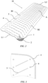
FIG. 1 is a schematic perspective view of an inflatable pad according to an example embodiment; -
FIG. 2 is a schematic structural diagram of the inflatable pad ofFIG. 1 ; -
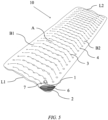
FIGS. 3 and3a are a partially enlarged schematic views of the inflatable pad ofFIG. 1 , according to two different patterns of the welding lines; -
FIG. 4 is a schematic diagram of a cut piece of a top piece of the inflatable pad ofFIG. 1 ; and -
FIG. 5 is a schematic structural diagram of the inflatable pad ofFIG. 1 comprising a thermal insulation layer. - Reference will now be made in detail to example embodiments which are illustrated in the accompanying drawings, wherein like reference numerals refer to like elements throughout. In this regard, the example embodiments may have different forms and may not be construed as being limited to the descriptions set forth herein.
- It will be understood that the terms "include," "including", "comprise, and/or "comprising," when used in this specification, specify the presence of stated features, integers, steps, operations, elements, and/or components, but do not preclude the presence or addition of one or more other features, integers, steps, operations, elements, components, and/or groups thereof.
- It will be further understood that, although the terms "first," "second," "third," etc., may be used herein to describe various elements, components, regions, layers and/or sections, these elements, components, regions, layers and/or sections may not be limited by these terms. These terms are only used to distinguish one element, component, region, layer or section from another element, component, region, layer or section.
- As used herein, the term "and/or" includes any and all combinations of one or more of the associated listed items. Expressions such as "at least one of," when preceding a list of elements, modify the entire list of elements and do not modify the individual elements of the list.
- Various terms are used to refer to particular system components. Different companies may refer to a component by different names - this document does not intend to distinguish between components that differ in name but not function.
- Matters of these example embodiments that are obvious to those of ordinary skill in the technical field to which these example embodiments pertain may not be described here in detail.
- As shown in
FIGs. 1 and2 , an inflatable pad according to an example embodiment comprises atop piece 1 and abottom piece 2 which are each substantially rectangular. Thetop piece 1 and thebottom piece 2 are welded to each other by means of regularly arrangedwelding points 4 andwelding lines 3. Specifically, a lower surface of the top piece and an upper surface of thebottom piece 2 are welded to each other by means of thewelding points 4 and thewelding lines 3. Thetop piece 1 and thebottom piece 2 are welded to each other along an outer periphery (i.e. an outerperiphery welding line 5 shown inFIGs. 3 or3a ) to form an inflatable chamber. One of thewelding points 4 is arranged at each end of each of the plurality ofwelding lines 3, and is spaced therefrom by a predetermined distance. Optionally, a predetermined distance between an end of eachwelding line 3 and thecorresponding welding point 4 may be less than or equal to 3 cm. For example, the predetermined distance may be 2 cm or 1 cm. The predetermined distance may be less than or equal to 5 mm. For example, the predetermined distance may be 4 mm or 3 mm. Optionally, thecorresponding welding point 4 may be arranged on an extension line of thewelding line 3. Furthermore, the diameter of thewelding point 4 is greater than the width of thewelding line 3. Arranging thewelding point 4 in this way may provide added protection to the end of thewelding line 3, so as to prevent the end of thewelding line 3 from being torn off. Accordingly, the use and service life of the inflatable pad may be improved. - As shown in
FIG. 3 , thewelding point 4 may be a ring shape, that is, the center of thewelding point 4 may be without welding. For example, one or more of the plurality of welding points may be a hollow circle. According to other example aspects, one or more of the plurality ofwelding points 4 may have any of a variety of other shapes. For example, one or more of the plurality of welding points may be a hollow ellipse. - The
top piece 1 and thebottom piece 2 of the inflatable pad can be made of TPU (thermoplastic polyurethane elastomer) composite fabric. According to an example aspect, thetop piece 1 and/or thebottom piece 2 can alternatively be made of PVC (polyvinyl chloride) material. - As shown in
FIG. 4 , the inflatable pad comprises, in its width direction, a central region A and two edge regions B1 and B2 located at opposite sides of the central region A in the width direction. Then the central region A and the two edge regions B1 and B2 extend along the longitudinal direction of the inflatable pad. The central region A comprises a plurality ofwelding points 4 arranged in a matrix. The two edge regions B1 and B2 each comprise a plurality ofwelding lines 3 arranged substantially parallel to each other and inclined with respect to a first edge L1 and a second edge L2 of the inflatable pad. The two edge regions B1 and B2 may further comprises each at least a row (or a column) of welding points 4. According to an example aspect shown inFIG. 3 , with the exception of the topmost row ofwelding points 4, opposite sides of each row ofwelding points 4 may be respectively provided withcorresponding welding lines 3. - Each row of
welding points 4 in the central region A may be evenly distributed, and a spacing between two adjacent rows ofwelding points 4 may be substantially the same. Accordingly, a spacing between twoadjacent welding lines 3 in the edge regions B1 and B2 may be substantially the same. Therefore, in an inflated state, the inflatable pad may maintain a flat surface, improving the comfort of use. Other arrangements of thewelding lines 3 can be possible, for example not parallel one to another but inclined.Discrete welding lines 3 may be arranged also betweenconsecutive welding points 4, disposed along the perimeter of the inflatable pad 1 (seefigure 3a ), in order to realize a sort of inner periphery welding line, to get reinforce the outerperiphery welding line 5. - There is an
inflation valve 7 disposed in a corner position. Due to the above-described inclined arrangement, the plurality ofwelding lines 3 may be avoided from intersecting theinflation valve 7, and the aesthetic effect of the inflatable pad may be improved. Preferably, theinflation valve 7 is disposed on thetop piece 1. - According to another example aspect, the
arrangement welding lines 3 and the welding points 4 is not limited to the specific arrangement described herein, and can also be arranged in any of a variety of other regular or irregular distribution forms. For example, the central region A may comprise a plurality ofwelding lines 3 which are substantially parallel to the first edge L1 and the second edge L2 of the inflatable pad, and one of the plurality ofwelding points 4 may be arranged at a certain distance from each end of each of the plurality ofwelding lines 3. The first edge L1 and the second edge L2 are parallel to each other and may be the longer sides of the inflatable pad or the shorter sides of the inflatable pad. - As shown in
FIG. 5 , in order to provide more comfort and warmth when used outdoors, the inflatable pad may further comprise athermal insulation layer 6 disposed between thetop piece 1 and thebottom piece 2, and thethermal insulation layer 6 may comprise a heat reflecting material, for example, an aluminized PET (polyethylene terephthalate) film. An air chamber formed between thetop piece 1 and thebottom piece 2 can also be filled with one or more thermal insulation materials (for example, flocculent polyester fibers) to achieve the purpose of thermal insulation. - Just to give some indications about the dimension of the pad, the thickness of the top/bottom sheet is between 0,15 mm±0,05mm and 0,3 mm±0,05mm, preferably about 0,2 mm±0,05mm. The height of the pad after being inflated is between 5 cm and 10cm. The distance between two adjacent rows of
welding points 4 in the central region A is between 5 cm and 12cm. - It may be understood that the example embodiments described herein may be considered in a descriptive sense only and not for purposes of limitation. Descriptions of features or aspects within each example embodiment may be considered as available for other similar features or aspects in other example embodiments.
- While example embodiments have been described with reference to the figures, it will be understood by those of ordinary skill in the art that various changes in form and details may be made therein without departing from the scope as defined by the following claims.
Claims (11)
- An inflatable pad (10), comprising:a top piece (1);a bottom piece (2) comprising an outer periphery welded to an outer periphery of the top piece (1), thereby defining an inflatable chamber between the top piece (1) and the bottom piece (2);a plurality of welding points (4) at which the top piece (1) is welded to the bottom piece (2); anda plurality of welding lines (3) along which the top piece (1) is welded to the bottom piece (2);wherein one of the plurality of welding points (4) is disposed a predetermined distance from each end of each of the plurality of welding lines (3).
- The inflatable pad according to claim 1, wherein the one of the plurality of welding points (4) disposed a predetermined distance from each end of each of the plurality of welding lines (3) is disposed on an extension line of a corresponding welding line (3).
- The inflatable pad according to claim 1, wherein a diameter of each of the plurality of welding points (4) is greater than a width of each of the plurality of welding lines (3).
- The inflatable pad according to claim 1, wherein the predetermined distance is less than or equal to 3 cm.
- The inflatable pad according to claim 1, wherein the predetermined distance is less than or equal to 5 mm.
- The inflatable pad according to claim 1, wherein each of the plurality of welding points (4) has a ring shape.
- The inflatable pad according to claim 1, wherein the inflatable pad (10) comprises a central region (A), a first edge region (B 1) disposed at a first side of the central region (A) in the width direction, and a second edge region (B2) disposed at a second side of the central region (A) in the width direction, wherein each of the first edge region (B 1) and the second edge region (B2) comprises a plurality of parallel welding lines (3).
- The inflatable pad according to claim 7, where the central region (A) comprises a plurality of welding points (4) arranged in a matrix.
- The inflatable pad according to claim 8, wherein the plurality of welding lines (3) and the plurality of welding points (4) is arranged such that there is an equal spacing between adjacent ones of the plurality of welding lines (3), and/or there is an equal spacing between adjacent rows of the plurality of welding points (4).
- The inflatable pad according to claim 1, wherein each of the top piece (1) and the bottom piece (2) is made of thermoplastic polyurethane elastomer.
- The inflatable pad according to claim 1, further comprising a thermal insulation layer (6) disposed between the top piece (1) and the bottom piece (2).
Applications Claiming Priority (1)
| Application Number | Priority Date | Filing Date | Title |
|---|---|---|---|
| CN202320239954.2U CN219645398U (en) | 2023-02-16 | 2023-02-16 | Inflatable cushion |
Publications (2)
| Publication Number | Publication Date |
|---|---|
| EP4417090A1 true EP4417090A1 (en) | 2024-08-21 |
| EP4417090B1 EP4417090B1 (en) | 2026-03-11 |
Family
ID=87570808
Family Applications (1)
| Application Number | Title | Priority Date | Filing Date |
|---|---|---|---|
| EP23190999.5A Active EP4417090B1 (en) | 2023-02-16 | 2023-08-11 | Inflatable pad |
Country Status (3)
| Country | Link |
|---|---|
| US (1) | US20240277165A1 (en) |
| EP (1) | EP4417090B1 (en) |
| CN (1) | CN219645398U (en) |
Families Citing this family (4)
| Publication number | Priority date | Publication date | Assignee | Title |
|---|---|---|---|---|
| CN220213883U (en) * | 2023-04-26 | 2023-12-22 | 上海荣威塑胶工业有限公司 | Water skiing cloth |
| USD1109554S1 (en) * | 2024-03-13 | 2026-01-20 | Shenzhen Xinpengcheng Outdoor Products Co., Ltd. | Inflatable mattress |
| USD1100545S1 (en) * | 2024-03-13 | 2025-11-04 | Shenzhen Xinpengcheng Outdoor Products Co., Ltd. | Inflatable mattress |
| USD1065880S1 (en) * | 2024-11-20 | 2025-03-11 | Dongguan Xintao Outdoor Products Co., Ltd. | Outdoor inflatable mattress |
Citations (2)
| Publication number | Priority date | Publication date | Assignee | Title |
|---|---|---|---|---|
| US20210030165A1 (en) * | 2019-07-29 | 2021-02-04 | Yiwu Jingtian Outdoor Products Co., Ltd. | Inflatable pad |
| CN113876144A (en) * | 2021-11-18 | 2022-01-04 | 义乌市景田户外用品有限公司 | Inflatable cushion |
-
2023
- 2023-02-16 CN CN202320239954.2U patent/CN219645398U/en active Active
- 2023-08-09 US US18/232,154 patent/US20240277165A1/en active Pending
- 2023-08-11 EP EP23190999.5A patent/EP4417090B1/en active Active
Patent Citations (2)
| Publication number | Priority date | Publication date | Assignee | Title |
|---|---|---|---|---|
| US20210030165A1 (en) * | 2019-07-29 | 2021-02-04 | Yiwu Jingtian Outdoor Products Co., Ltd. | Inflatable pad |
| CN113876144A (en) * | 2021-11-18 | 2022-01-04 | 义乌市景田户外用品有限公司 | Inflatable cushion |
Also Published As
| Publication number | Publication date |
|---|---|
| CN219645398U (en) | 2023-09-08 |
| US20240277165A1 (en) | 2024-08-22 |
| EP4417090B1 (en) | 2026-03-11 |
Similar Documents
| Publication | Publication Date | Title |
|---|---|---|
| EP4417090B1 (en) | Inflatable pad | |
| US5437068A (en) | Body-conforming, multi-foldable, inflatable mattress having phase-shifted sinusoidal seals | |
| US11641948B2 (en) | Inflatable bed | |
| US5708999A (en) | Adjustable therapeutic pillow | |
| US8449968B2 (en) | Cellular cushioning article | |
| EP1315434B1 (en) | Multi-chamber airbed | |
| US4378391A (en) | Advertising novelty | |
| US10136736B2 (en) | Under mattress support | |
| US3618144A (en) | Cushioning assembly | |
| EP2018110A4 (en) | SINGLE PATIENT, PNEUMATIC USE MATTRESS FOR PERSONAL USE WITH SINGLE PERIPHERAL SEWING | |
| EP3490411B1 (en) | Inflatable airbed mattress internal support system | |
| US5053262A (en) | Child's serving mat | |
| US8656540B2 (en) | Air mattress | |
| SE540906C2 (en) | Massage cell arrangement and massage cell system | |
| SE540804C2 (en) | Massage cell arrangement and massage cell system | |
| US20190246805A1 (en) | Inflatable product | |
| JP2016005535A (en) | Mat filled with liquid | |
| US3066928A (en) | Resilient cushion structure | |
| US20050081299A1 (en) | Inflatable bed | |
| US5027458A (en) | Collapsible heat insulating mattress having foam lattice cells and a slit foil sheet covering | |
| KR102167787B1 (en) | A Cool mat for double-sided use | |
| US3255469A (en) | Pneumatic cushion | |
| EP4371818B1 (en) | Pneumatic mat with improved shape | |
| AU2007225427B2 (en) | New and improved tier sheet | |
| KR102096097B1 (en) | a colling neck pillow |
Legal Events
| Date | Code | Title | Description |
|---|---|---|---|
| PUAI | Public reference made under article 153(3) epc to a published international application that has entered the european phase |
Free format text: ORIGINAL CODE: 0009012 |
|
| STAA | Information on the status of an ep patent application or granted ep patent |
Free format text: STATUS: THE APPLICATION HAS BEEN PUBLISHED |
|
| AK | Designated contracting states |
Kind code of ref document: A1 Designated state(s): AL AT BE BG CH CY CZ DE DK EE ES FI FR GB GR HR HU IE IS IT LI LT LU LV MC ME MK MT NL NO PL PT RO RS SE SI SK SM TR |
|
| STAA | Information on the status of an ep patent application or granted ep patent |
Free format text: STATUS: REQUEST FOR EXAMINATION WAS MADE |
|
| 17P | Request for examination filed |
Effective date: 20250121 |
|
| GRAP | Despatch of communication of intention to grant a patent |
Free format text: ORIGINAL CODE: EPIDOSNIGR1 |
|
| STAA | Information on the status of an ep patent application or granted ep patent |
Free format text: STATUS: GRANT OF PATENT IS INTENDED |
|
| INTG | Intention to grant announced |
Effective date: 20251110 |
|
| GRAS | Grant fee paid |
Free format text: ORIGINAL CODE: EPIDOSNIGR3 |
|
| GRAA | (expected) grant |
Free format text: ORIGINAL CODE: 0009210 |
|
| STAA | Information on the status of an ep patent application or granted ep patent |
Free format text: STATUS: THE PATENT HAS BEEN GRANTED |
|
| AK | Designated contracting states |
Kind code of ref document: B1 Designated state(s): AL AT BE BG CH CY CZ DE DK EE ES FI FR GB GR HR HU IE IS IT LI LT LU LV MC ME MK MT NL NO PL PT RO RS SE SI SK SM TR |
|
| REG | Reference to a national code |
Ref country code: CH Ref legal event code: F10 Free format text: ST27 STATUS EVENT CODE: U-0-0-F10-F00 (AS PROVIDED BY THE NATIONAL OFFICE) Effective date: 20260311 Ref country code: GB Ref legal event code: FG4D |
|
| REG | Reference to a national code |
Ref country code: DE Ref legal event code: R096 Ref document number: 602023013257 Country of ref document: DE |
|
| REG | Reference to a national code |
Ref country code: IE Ref legal event code: FG4D |