EP4417085A1 - Content container - Google Patents
Content container Download PDFInfo
- Publication number
- EP4417085A1 EP4417085A1 EP22881280.6A EP22881280A EP4417085A1 EP 4417085 A1 EP4417085 A1 EP 4417085A1 EP 22881280 A EP22881280 A EP 22881280A EP 4417085 A1 EP4417085 A1 EP 4417085A1
- Authority
- EP
- European Patent Office
- Prior art keywords
- protrusion
- content container
- shoulder
- discharge
- communication hole
- Prior art date
- Legal status (The legal status is an assumption and is not a legal conclusion. Google has not performed a legal analysis and makes no representation as to the accuracy of the status listed.)
- Pending
Links
Images



Classifications
-
- B—PERFORMING OPERATIONS; TRANSPORTING
- B65—CONVEYING; PACKING; STORING; HANDLING THIN OR FILAMENTARY MATERIAL
- B65D—CONTAINERS FOR STORAGE OR TRANSPORT OF ARTICLES OR MATERIALS, e.g. BAGS, BARRELS, BOTTLES, BOXES, CANS, CARTONS, CRATES, DRUMS, JARS, TANKS, HOPPERS, FORWARDING CONTAINERS; ACCESSORIES, CLOSURES, OR FITTINGS THEREFOR; PACKAGING ELEMENTS; PACKAGES
- B65D41/00—Caps, e.g. crown caps or crown seals, i.e. members having parts arranged for engagement with the external periphery of a neck or wall defining a pouring opening or discharge aperture; Protective cap-like covers for closure members, e.g. decorative covers of metal foil or paper
- B65D41/02—Caps or cap-like covers without lines of weakness, tearing strips, tags, or like opening or removal devices
- B65D41/04—Threaded or like caps or cap-like covers secured by rotation
-
- B—PERFORMING OPERATIONS; TRANSPORTING
- B65—CONVEYING; PACKING; STORING; HANDLING THIN OR FILAMENTARY MATERIAL
- B65D—CONTAINERS FOR STORAGE OR TRANSPORT OF ARTICLES OR MATERIALS, e.g. BAGS, BARRELS, BOTTLES, BOXES, CANS, CARTONS, CRATES, DRUMS, JARS, TANKS, HOPPERS, FORWARDING CONTAINERS; ACCESSORIES, CLOSURES, OR FITTINGS THEREFOR; PACKAGING ELEMENTS; PACKAGES
- B65D47/00—Closures with filling and discharging, or with discharging, devices
- B65D47/04—Closures with discharging devices other than pumps
- B65D47/06—Closures with discharging devices other than pumps with pouring spouts or tubes; with discharge nozzles or passages
- B65D47/061—Closures with discharging devices other than pumps with pouring spouts or tubes; with discharge nozzles or passages with telescopic, retractable or reversible spouts, tubes or nozzles
-
- A—HUMAN NECESSITIES
- A45—HAND OR TRAVELLING ARTICLES
- A45D—HAIRDRESSING OR SHAVING EQUIPMENT; EQUIPMENT FOR COSMETICS OR COSMETIC TREATMENTS, e.g. FOR MANICURING OR PEDICURING
- A45D34/00—Containers or accessories specially adapted for handling liquid toiletry or cosmetic substances, e.g. perfumes
- A45D34/04—Appliances specially adapted for applying liquid, e.g. using roller or ball
-
- A—HUMAN NECESSITIES
- A45—HAND OR TRAVELLING ARTICLES
- A45D—HAIRDRESSING OR SHAVING EQUIPMENT; EQUIPMENT FOR COSMETICS OR COSMETIC TREATMENTS, e.g. FOR MANICURING OR PEDICURING
- A45D40/00—Casings or accessories specially adapted for storing or handling solid or pasty toiletry or cosmetic substances, e.g. shaving soaps or lipsticks
- A45D40/26—Appliances specially adapted for applying pasty paint, e.g. using roller, using a ball
-
- B—PERFORMING OPERATIONS; TRANSPORTING
- B65—CONVEYING; PACKING; STORING; HANDLING THIN OR FILAMENTARY MATERIAL
- B65D—CONTAINERS FOR STORAGE OR TRANSPORT OF ARTICLES OR MATERIALS, e.g. BAGS, BARRELS, BOTTLES, BOXES, CANS, CARTONS, CRATES, DRUMS, JARS, TANKS, HOPPERS, FORWARDING CONTAINERS; ACCESSORIES, CLOSURES, OR FITTINGS THEREFOR; PACKAGING ELEMENTS; PACKAGES
- B65D43/00—Lids or covers for rigid or semi-rigid containers
- B65D43/02—Removable lids or covers
-
- B—PERFORMING OPERATIONS; TRANSPORTING
- B65—CONVEYING; PACKING; STORING; HANDLING THIN OR FILAMENTARY MATERIAL
- B65D—CONTAINERS FOR STORAGE OR TRANSPORT OF ARTICLES OR MATERIALS, e.g. BAGS, BARRELS, BOTTLES, BOXES, CANS, CARTONS, CRATES, DRUMS, JARS, TANKS, HOPPERS, FORWARDING CONTAINERS; ACCESSORIES, CLOSURES, OR FITTINGS THEREFOR; PACKAGING ELEMENTS; PACKAGES
- B65D47/00—Closures with filling and discharging, or with discharging, devices
- B65D47/04—Closures with discharging devices other than pumps
- B65D47/06—Closures with discharging devices other than pumps with pouring spouts or tubes; with discharge nozzles or passages
-
- B—PERFORMING OPERATIONS; TRANSPORTING
- B65—CONVEYING; PACKING; STORING; HANDLING THIN OR FILAMENTARY MATERIAL
- B65D—CONTAINERS FOR STORAGE OR TRANSPORT OF ARTICLES OR MATERIALS, e.g. BAGS, BARRELS, BOTTLES, BOXES, CANS, CARTONS, CRATES, DRUMS, JARS, TANKS, HOPPERS, FORWARDING CONTAINERS; ACCESSORIES, CLOSURES, OR FITTINGS THEREFOR; PACKAGING ELEMENTS; PACKAGES
- B65D47/00—Closures with filling and discharging, or with discharging, devices
- B65D47/04—Closures with discharging devices other than pumps
- B65D47/06—Closures with discharging devices other than pumps with pouring spouts or tubes; with discharge nozzles or passages
- B65D47/12—Closures with discharging devices other than pumps with pouring spouts or tubes; with discharge nozzles or passages having removable closures
- B65D47/122—Threaded caps
-
- B—PERFORMING OPERATIONS; TRANSPORTING
- B65—CONVEYING; PACKING; STORING; HANDLING THIN OR FILAMENTARY MATERIAL
- B65D—CONTAINERS FOR STORAGE OR TRANSPORT OF ARTICLES OR MATERIALS, e.g. BAGS, BARRELS, BOTTLES, BOXES, CANS, CARTONS, CRATES, DRUMS, JARS, TANKS, HOPPERS, FORWARDING CONTAINERS; ACCESSORIES, CLOSURES, OR FITTINGS THEREFOR; PACKAGING ELEMENTS; PACKAGES
- B65D47/00—Closures with filling and discharging, or with discharging, devices
- B65D47/04—Closures with discharging devices other than pumps
- B65D47/06—Closures with discharging devices other than pumps with pouring spouts or tubes; with discharge nozzles or passages
- B65D47/18—Closures with discharging devices other than pumps with pouring spouts or tubes; with discharge nozzles or passages for discharging drops; Droppers
-
- B—PERFORMING OPERATIONS; TRANSPORTING
- B65—CONVEYING; PACKING; STORING; HANDLING THIN OR FILAMENTARY MATERIAL
- B65D—CONTAINERS FOR STORAGE OR TRANSPORT OF ARTICLES OR MATERIALS, e.g. BAGS, BARRELS, BOTTLES, BOXES, CANS, CARTONS, CRATES, DRUMS, JARS, TANKS, HOPPERS, FORWARDING CONTAINERS; ACCESSORIES, CLOSURES, OR FITTINGS THEREFOR; PACKAGING ELEMENTS; PACKAGES
- B65D47/00—Closures with filling and discharging, or with discharging, devices
- B65D47/04—Closures with discharging devices other than pumps
- B65D47/20—Closures with discharging devices other than pumps comprising hand-operated members for controlling discharge
Definitions
- the present invention relates to a content container, and more specifically, to a content container, which can tightly seal the contents in a locked state and release the locked state by simply rotating an overcap to allow the contents to be discharged.
- a dropper-type cosmetic container is configured to allow a discharge portion having a pipette to be detachably attached to a container.
- a dropper-type cosmetic container in a state in which the pipette is inserted into the container, is implemented to suck and discharge the contents when a user presses a button.
- a tube-type cosmetic container in a state in which a pipette-shaped nozzle is coupled to one end thereof, is implemented to discharge the contents through the nozzle when the user directly presses the container.
- the cosmetic containers can suck and directly discharge a small amount of contents to an application area, and minimize exposure of the contents to the external environment during storage and use, so are widely adopted for containers for functional cosmetics such as serum, essence, and eye cream.
- the dropper-type cosmetic cosmetic containers have a limitation in that it is insufficient to protect the contents from being deteriorated by external environments.
- the present invention has been made in view of the above-mentioned problems occurring in the related art, and it is an objective of the present invention to provide a content container, which can tightly seal the contents in a locked state and release the locked state by simply rotating an overcap to allow the contents to be discharged.
- a content container including: a container body accommodating contents; a neck portion which is formed on the top of the container body and has an opening portion formed therein to communicate with the inside of the container body; and a discharge portion, of which at least a portion is accommodated in the neck portion so as to seal the opening portion, and which has a nozzle portion formed at the upper portion thereof to discharge the contents, wherein the discharge portion has at least one communication hole formed in the bottom of the discharge portion to transfer the contents of the content container to the nozzle portion, and when the discharge portion descends from a first position to a second position by an external force of a user, the communication hole is exposed to the inside of the container body so that the contents in the container body can be transferred to the nozzle portion via the communication hole.
- the communication hole is positioned above the opening portion in the first position of the discharge portion to be blocked from the inside of the content container, and when the discharge portion descends to the second position, the communication hole is positioned below the opening portion to communicate with the inside of the container body.
- At least one first coupling protrusion and at least one second coupling protrusion are respectively formed on the bottom and the top of the communication hole to be spaced apart from each other, and coupling grooves corresponding to the first and second coupling protrusions are formed on the inner surface of the opening portion.
- the first coupling protrusion is coupled to the coupling groove in the first position of the discharge portion such that the communication hole is located above the opening portion
- the second coupling protrusion is coupled to the coupling groove in the second position of the discharge portion such that the communication hole is located below the opening portion.
- the content container further includes a shoulder portion coupled to the outer side of the neck portion to fix the discharge portion to the neck portion, wherein as the shoulder portion rotates in the first direction, the discharge portion descends with the shoulder portion.
- At least one rotation prevention protrusion is formed on the outer surface of the bottom of the neck portion to prevent the shoulder portion from rotating in the second direction opposed to the first direction.
- the content container further includes an overcap coupled to the top of the shoulder portion to cover the nozzle portion to shield the nozzle portion, wherein when the overcap is rotated in the first direction, the shoulder portion rotates with the overcap in the first direction.
- the overcap when the overcap is rotated in the second direction, the overcap is separated from the shoulder portion.
- At least one retaining protrusion is formed on the inner bottom surface of the shoulder portion, and the rotation prevention protrusion forms a slope surface on the outer side as the protrusion height of the rotation prevention protrusion increases in the first direction.
- the retaining protrusion is formed in such a way that the protrusion height of the retaining protrusion increases in the second direction.
- the content container further includes a stopper portion placed between the neck portion and the shoulder portion to cover the neck portion, thereby preventing the descent of the shoulder portion due to the first-direction rotation.
- the content container can prevent leakage and deterioration of the contents by effectively sealing the neck portion and/or the container body through the discharge portion in the locked state.
- the content container can lower the discharge portion just by rotating the overcap in one direction to release the locked state, thereby increasing the convenience of manipulation for the user.
- FIG. 1 is a cross-sectional view of a content container according to an embodiment of the present invention
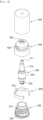
- FIG. 2 is an exploded perspective view of the content container according to the embodiment of the present invention
- FIG. 3 is a perspective view and a cross-sectional view of a neck portion according to the embodiment of the present invention
- FIG. 4 is an exploded perspective view and a cross-sectional view of a discharge portion according to the embodiment of the present invention
- FIG. 5 is a perspective view of a shoulder portion according to the embodiment of the present invention.
- FIG. 1 only the upper part of a container body 100 is illustrated, and in FIG. 2 , the container body 100 is omitted for the convenience of description.
- the content container 1000 may include a container body 100, a neck portion 200, a discharge portion 300, a shoulder portion 400, an overcap 500, and a stopper portion 600.
- the container body 100 is open at the top and sealed at the bottom, and has an inner space for accommodating contents.
- the contents accommodated in the container body 100 can be discharged by a nozzle portion 310 of the discharge portion 300 and can be used by a user.
- the contents may be in liquid or gel form, such as cosmetics, pharmaceuticals, or quasi-drugs like oral care products, but are not limited thereto, and may encompass all types of materials that can be discharged through the nozzle portion 310.
- a tube type container body 100 is desirable, but it is exemplary, and various types of container bodies 100 such as bottles can be applied.
- the neck portion 200 is coupled to the open top of the container body 100, and can connect other components of the content container 1000 to the container body 100.
- the bottom of the neck portion 200 can be inserted into the open top of the container body 100, and can be attached to the inner top surface of the container body 100.
- a first screw coupling portion 210 can be formed on the outer peripheral surface of the neck portion 200.
- the shoulder portion 400 can be detachably coupled to the neck portion 200 through the first screw coupling portion 210.
- the neck portion 200 is open at the top to form an inner accommodation space, and an opening portion 230 can be formed at the inner bottom of the neck portion 200.
- an inner peripheral edge 220 can be formed by extending from a point on the inner side of the neck portion 200 inwardly, and an opening portion 230 penetrating vertically can be formed at the center of the inner peripheral edge 220.
- the opening portion 230 can communicate with the interior of the container body 100.
- a coupling groove 231 can be formed on the inner surface of the opening portion 230.
- the coupling groove 231 can be formed in a ring shape along the inner peripheral surface of the opening portion 230.
- At least one rotation prevention protrusion 240 can be formed on the outer bottom surface of the neck portion 200.
- a plurality of rotation prevention protrusions 240 can be formed along the outer peripheral surface of the bottom of the neck portion 200.
- the rotation prevention protrusion 240 can function to restrict the rotation direction of the shoulder portion 400 to a first direction together with a retaining protrusion 440 of the shoulder portion 400.
- the rotation prevention protrusion 240 may have a slope surface 241 formed on the outer surface thereof as the outward protrusion height increases in the first direction. Accordingly, the shoulder portion 400 can rotate in the first direction. However, when attempting to rotate in the second direction opposed to the first direction, the retaining protrusion 440 of the shoulder portion 400 may engage with the first direction end of the rotation prevention protrusion 240, thereby restricting the rotation in the second direction.
- a cut portion 242 may be formed on one side of the rotation prevention protrusion 240.
- the cut portion 242 can be formed by diagonally cutting the upper portion of the end of the rotation prevention protrusion 240 in the second direction. As will be described with reference to FIG. 6 , due to the cut portion 242, it may be easier to initially rotate the shoulder portion 400 in the first direction for unlocking the content container 1000.
- At least a portion of the discharge portion 300 is accommodated inside the neck portion 200 through the open top of the neck portion 200, and the bottom of the discharge portion 300 is forcedly fit to the opening portion 230 of the neck portion 200 to seal the opening portion 230. Additionally, the discharge portion 300 can descend from the first position inside the neck portion 200 to the second position in response to the first-direction rotation of the shoulder portion 400 and/or the overcap 500.
- the discharge portion 300 can be positioned at the first position, and as the discharge portion 300 descends to the second position, the content container 1000 is unlocked, such that the contents can be discharged through the discharge portion 300.
- the discharge portion 300 may include a nozzle portion 310, a housing portion 320, a check valve 330, and a control cap 340.
- the nozzle portion 310 may protrude outward from the neck portion 200 and the shoulder portion 400 to discharge contents through an outlet 311 formed at the end thereof.
- the nozzle portion 310 may be configured, for example, as a pipette tube or a pipette shape having a hollow formed therein, but is not limited thereto.
- the bottom of the nozzle portion 310 may be inserted and forcedly fit into the housing portion 320.
- Coupling protrusions and/or coupling grooves may be formed on the bottom outer surface of the nozzle portion 310 and/or the top inner surface of the housing portion 320 for coupling.
- At least a portion of the housing portion 320 may be accommodated inside the neck portion 200 and the bottom of the housing portion 320 is forcedly fit to the opening portion 230 of the neck portion 200 to seal the opening portion 230. Additionally, when the discharge portion 300 descends to the second position, the housing portion 320 can communicate with the interior of the container body 100 to transfer the contents to the nozzle portion 310 connected to the top.
- a sealing portion 321 may be formed on the bottom of the housing portion 320.
- a portion of the housing portion 320, including the top may be formed to correspond to the accommodation space of the neck portion 200, and the sealing portion 321 formed at the bottom may be formed to correspond to the opening portion 230.
- the housing portion 320 When the discharge portion 300 is inserted into the neck portion 200 up to the first position, the housing portion 320 may be accommodated inside the accommodation space of the neck portion 200, and the sealing portion 321 may be inserted into the opening portion 230 to seal the opening portion 230.
- the top of the housing portion 320 is comes into close contact with the inner wall of the neck portion 200, such that the neck portion 200 and the container body 100 can be doubly sealed by the housing portion 320.
- At least one communication hole 322 may be formed in the side of the sealing portion 321 to penetrate through the inside.
- the communication hole 322 When the discharge portion 300 is in the first position (locked state), the communication hole 322 is positioned above the opening portion 230, and as the discharge portion 300 descends to the second position (unlocked state), the communication hole 322 moves downward below the opening portion 230 to be exposed into the the container body 100.
- At least one first coupling protrusion 323 and at least one second coupling protrusion 324 may be respectively formed on the bottom and the top of the communication hole 322 to be spaced apart from each other.
- the first coupling protrusion 323 may be coupled to the coupling groove 231 of the opening portion 230.
- the first coupling protrusion 323 may be separated from the coupling groove 231, and the second coupling protrusion 324 may be coupled to the coupling groove 231.
- the sealing performance can be improved further.
- the check valve 330 may be positioned at the top of the sealing portion 321 to seal the inner bottom of the housing portion 320.
- the check valve 330 is opened due to the pressure of the contents flowing into the communication hole 322 to allow the contents to be transferred to the nozzle portion 310.
- the control cap 340 may be forcedly fit into the bottom of the nozzle portion 310 and may be positioned inside the housing portion 320.
- the control cap 340 can control the amount and/or speed of the contents transferred to the nozzle portion 310 when pressure is applied to the container body 100.
- a predetermined shape of content movement hole (no reference numeral) may be formed penetratingly in the control cap 340.
- the content movement hole may be configured to have an inner diameter increasing in the direction of the outlet 311.
- the shoulder portion 400 can be coupled to the outer side of the neck portion 200 to fix the discharge portion 300 to the neck portion 200.
- a second screw coupling portion 410 corresponding to the first screw coupling portion 210 of the neck portion 200 may be formed on the inner peripheral surface of the shoulder portion 400, and a through hole through which the nozzle portion 310 passes may be formed at the top of the shoulder portion 400, and a pressing edge 420 may protrude downward along the perimeter of the through hole.
- the shoulder portion 400 when the shoulder portion 400 is rotated in the first direction, the shoulder portion 400 can be coupled to the neck portion 200, and the pressing edge 420 can press against the perimeter of the nozzle portion 310 protruding outward from the neck portion 200, thereby fixing the discharge portion 300.
- a third screw coupling portion 430 may be formed on the outer surface of the shoulder portion 400. Accordingly, an overcap 500 may be detachably coupled to the upper side of the shoulder portion 400.
- the shoulder portion 400 can be rotated in the first direction by external force, so the discharge portion 300 is pressed to lower the discharge portion 300 from the first position to the second position.
- At least one retaining protrusion 440 may be formed on the inner bottom surface of the shoulder portion 400.
- the retaining protrusions 440 may be formed at predetermined intervals along the inner peripheral surface of the bottom of the shoulder portion 400. As described above, the retaining protrusions 440, together with the rotation prevention protrusions 240 of the neck portion 200, can restrict the second-direction rotation of the shoulder portion 400.
- a slope surface corresponding to the slope surface 241 of the rotation prevention protrusion 240 may be formed on the outer surface of the retaining protrusion 440.
- the overcap 500 can be detachably coupled to the shoulder portion 400 to cover the nozzle portion 310 from the outside to shield the nozzle portion 310.
- a fourth screw coupling portion 510 corresponding to the third screw coupling portion 430 of the shoulder portion 400 may be formed on the inner bottom surface of the overcap 500.
- a nozzle tip receiving portion 520 in which the end of the nozzle portion 310 having the outlet 311 is accommodated, can be formed on the inner top surface of the overcap 500. At least a portion of the nozzle tip receiving portion 520 is formed to be recessed to correspond to the shape of the end of the nozzle portion 310. When the overcap 500 is coupled, the end of the nozzle portion 310 can be inserted into the nozzle tip receiving portion 520 to seal (or shield) the outlet 311.
- the shoulder portion 400 can receive the force from the overcap 500 and rotate together with the overcap 500 in the first direction.
- the stopper portion 600 is formed in a ring shape opened at one side, is coupled to cover the bottom of the neck portion 200 (for example, the portion where the rotation prevention protrusion 240 is formed), and can be placed between the neck portion 200 and the shoulder portion 400. By supporting the bottom of the shoulder portion 400, the stopper portion 600 can prevent the locking state of the content container 1000 from being released by the descent of the shoulder portion 400.
- At least one second retaining protrusion 610 may be formed on the inner peripheral surface of the stopper portion 600. When the second retaining protrusion 610 is caught to the rotation prevention protrusion 240 of the neck portion 200, the rotation of the stopper portion 600 can be prevented.
- FIG. 6 is a diagram illustrating the coupling relationship of the content container according to the embodiment of the present invention.
- FIG. 6 illustrates the coupling relationship of the neck portion 200, the discharge portion 300, and the shoulder portion 400 in the locked state of the content container 1000.
- the bottom of the shoulder portion 400 can be maintained at a predetermined distance from the bottom of the neck portion 200 or the top of the container body 100.
- the bottom of the retaining protrusion 440 of the shoulder portion 400 can be positioned on a space formed between two adjacent rotation prevention protrusions 240 by the cut portion 242.
- FIGS. 7 and 8 illustrate an exemplary operation of the content container according to the embodiment of the present invention.
- the communication hole 322 of the discharge portion 300 is positioned above the opening portion 230 to be blocked from the inside of the container body 100, and the opening portion 230 can be completely sealed by the bottom of the housing portion 320.
- the content container 1000 can be converted into the unlocked state. That is, the shoulder portion 400 descends while rotating in the first direction due to the rotation of the overcap 500, and the discharge portion 300 can descend to the second position. As a result, the communication hole 322 is positioned below the opening portion 230 to communicate with the inside of the container body 100, such that the content container 1000 is unlocked.
- the user can remove the overcap 500 from the shoulder portion 400 by rotating the overcap 500 in the second direction. That is, when rotating the overcap 500 in the second direction, the shoulder portion 400 does not rotate with the overcap 500 by the rotation prevention protrusion 240 and is fixed to the neck portion 200, so only the overcap 500 can be removed from the shoulder portion 400.
- the contents can be introduced into the communication hole 322, pass through the inside of the housing portion 320, and then, be discharged through the nozzle portion 310.
Landscapes
- Engineering & Computer Science (AREA)
- Mechanical Engineering (AREA)
- Closures For Containers (AREA)
Abstract
Description
- The present invention relates to a content container, and more specifically, to a content container, which can tightly seal the contents in a locked state and release the locked state by simply rotating an overcap to allow the contents to be discharged.
- In general, a dropper-type cosmetic container is configured to allow a discharge portion having a pipette to be detachably attached to a container. A dropper-type cosmetic container, in a state in which the pipette is inserted into the container, is implemented to suck and discharge the contents when a user presses a button. Alternatively, a tube-type cosmetic container, in a state in which a pipette-shaped nozzle is coupled to one end thereof, is implemented to discharge the contents through the nozzle when the user directly presses the container.
- The cosmetic containers can suck and directly discharge a small amount of contents to an application area, and minimize exposure of the contents to the external environment during storage and use, so are widely adopted for containers for functional cosmetics such as serum, essence, and eye cream.
- However, in a case in which functional substances prone to chemical changes due to external environments, such as retinol, vitamins, etc., are included in the contents, since the contents may be deteriorated due to exposure to light, oxygen, moisture, etc., during the distribution, storage, and other processes of cosmetic containers, the dropper-type cosmetic cosmetic containers have a limitation in that it is insufficient to protect the contents from being deteriorated by external environments.
- Therefore, there is a demand for technology to solve the problem.
- Accordingly, the present invention has been made in view of the above-mentioned problems occurring in the related art, and it is an objective of the present invention to provide a content container, which can tightly seal the contents in a locked state and release the locked state by simply rotating an overcap to allow the contents to be discharged.
- The objectives of the present invention are not limited to those mentioned above, and other objectives not mentioned herein will be clearly understood by those skilled in the art from the following description.
- To accomplish the above-mentioned objects, according to the present invention, there is provided a content container including: a container body accommodating contents; a neck portion which is formed on the top of the container body and has an opening portion formed therein to communicate with the inside of the container body; and a discharge portion, of which at least a portion is accommodated in the neck portion so as to seal the opening portion, and which has a nozzle portion formed at the upper portion thereof to discharge the contents, wherein the discharge portion has at least one communication hole formed in the bottom of the discharge portion to transfer the contents of the content container to the nozzle portion, and when the discharge portion descends from a first position to a second position by an external force of a user, the communication hole is exposed to the inside of the container body so that the contents in the container body can be transferred to the nozzle portion via the communication hole.
- Moreover, the communication hole is positioned above the opening portion in the first position of the discharge portion to be blocked from the inside of the content container, and when the discharge portion descends to the second position, the communication hole is positioned below the opening portion to communicate with the inside of the container body.
- Furthermore, on the outer side of the bottom of the discharge portion, at least one first coupling protrusion and at least one second coupling protrusion are respectively formed on the bottom and the top of the communication hole to be spaced apart from each other, and coupling grooves corresponding to the first and second coupling protrusions are formed on the inner surface of the opening portion. The first coupling protrusion is coupled to the coupling groove in the first position of the discharge portion such that the communication hole is located above the opening portion, and the second coupling protrusion is coupled to the coupling groove in the second position of the discharge portion such that the communication hole is located below the opening portion.
- In addition, the content container further includes a shoulder portion coupled to the outer side of the neck portion to fix the discharge portion to the neck portion, wherein as the shoulder portion rotates in the first direction, the discharge portion descends with the shoulder portion.
- Additionally, at least one rotation prevention protrusion is formed on the outer surface of the bottom of the neck portion to prevent the shoulder portion from rotating in the second direction opposed to the first direction.
- Moreover, the content container further includes an overcap coupled to the top of the shoulder portion to cover the nozzle portion to shield the nozzle portion, wherein when the overcap is rotated in the first direction, the shoulder portion rotates with the overcap in the first direction.
- Furthermore, when the overcap is rotated in the second direction, the overcap is separated from the shoulder portion.
- Additionally, at least one retaining protrusion is formed on the inner bottom surface of the shoulder portion, and the rotation prevention protrusion forms a slope surface on the outer side as the protrusion height of the rotation prevention protrusion increases in the first direction. When the shoulder portion is rotated in the second direction, the retaining protrusion is caught to the first-direction end of the rotation prevention protrusion, thereby preventing rotation of the shoulder portion in the second direction.
- In addition, the retaining protrusion is formed in such a way that the protrusion height of the retaining protrusion increases in the second direction.
- Moreover, the content container further includes a stopper portion placed between the neck portion and the shoulder portion to cover the neck portion, thereby preventing the descent of the shoulder portion due to the first-direction rotation.
- According to the present invention, the content container can prevent leakage and deterioration of the contents by effectively sealing the neck portion and/or the container body through the discharge portion in the locked state.
- Additionally, according to the present invention, the content container can lower the discharge portion just by rotating the overcap in one direction to release the locked state, thereby increasing the convenience of manipulation for the user.
- A brief description of each drawing is provided for better understanding of the drawings referred to in the detailed description of the present invention.
-
FIG. 1 is a cross-sectional view of a content container according to an embodiment of the present invention. -
FIG. 2 is an exploded perspective view of the content container according to the embodiment of the present invention. -
FIG. 3 is a perspective view and a cross-sectional view of a neck portion according to the embodiment of the present invention. -
FIG. 4 is an exploded perspective view and a cross-sectional view of a discharge portion according to the embodiment of the present invention. -
FIG. 5 is a perspective view of a shoulder portion according to the embodiment of the present invention. -
FIG. 6 is a diagram illustrating the coupling relationship of the content container according to the embodiment of the present invention. -
FIGS. 7 and8 illustrate an exemplary operation of the content container according to the embodiment of the present invention. - Hereinafter, exemplary embodiments of the present invention will be described with reference to the accompanying drawings. In the following description, the same components will be designated by the same reference numerals although they are shown in different drawings. Furthermore, in the following description of the present invention, a detailed description of known functions and configurations incorporated herein will be omitted when it may make the subject matter of the present invention rather unclear. In addition, a preferred embodiment of the present invention will be described hereinbelow, the technical thought of the present invention is not restricted or limited thereto and may be embodied in various manners through modification by those skilled in the art. For convenience, directions such as top, bottom, left, and right mentioned below are based on the drawings, and it should be noted that the scope of the present invention is not necessarily limited by the directions.
- Throughout the specification, when one part is "connected" to another part, it includes not only being "directly connected" but also being "indirectly connected" with another component in between. Moreover, when one part "includes" another component in the specification, it means that the part includes other components unless specifically stated otherwise, rather than excluding other components. Furthermore, in describing components of the embodiment of the present invention, terms such as first, second, A, B, (a), (b), etc., may be used. The terms are used to distinguish the components from other components, and the essence, order, or sequence of the components is not limited by the terms.
-
FIG. 1 is a cross-sectional view of a content container according to an embodiment of the present invention,FIG. 2 is an exploded perspective view of the content container according to the embodiment of the present invention,FIG. 3 is a perspective view and a cross-sectional view of a neck portion according to the embodiment of the present invention,FIG. 4 is an exploded perspective view and a cross-sectional view of a discharge portion according to the embodiment of the present invention, andFIG. 5 is a perspective view of a shoulder portion according to the embodiment of the present invention. - Meanwhile, in
FIG. 1 , only the upper part of acontainer body 100 is illustrated, and inFIG. 2 , thecontainer body 100 is omitted for the convenience of description. - Referring to
FIGS. 1 to 5 , thecontent container 1000 may include acontainer body 100, aneck portion 200, adischarge portion 300, ashoulder portion 400, anovercap 500, and astopper portion 600. - The
container body 100 is open at the top and sealed at the bottom, and has an inner space for accommodating contents. The contents accommodated in thecontainer body 100 can be discharged by anozzle portion 310 of thedischarge portion 300 and can be used by a user. Here, the contents may be in liquid or gel form, such as cosmetics, pharmaceuticals, or quasi-drugs like oral care products, but are not limited thereto, and may encompass all types of materials that can be discharged through thenozzle portion 310. Additionally, a tubetype container body 100 is desirable, but it is exemplary, and various types ofcontainer bodies 100 such as bottles can be applied. - The
neck portion 200 is coupled to the open top of thecontainer body 100, and can connect other components of thecontent container 1000 to thecontainer body 100. For example, the bottom of theneck portion 200 can be inserted into the open top of thecontainer body 100, and can be attached to the inner top surface of thecontainer body 100. Additionally, a firstscrew coupling portion 210 can be formed on the outer peripheral surface of theneck portion 200. Theshoulder portion 400 can be detachably coupled to theneck portion 200 through the firstscrew coupling portion 210. - The
neck portion 200 is open at the top to form an inner accommodation space, and anopening portion 230 can be formed at the inner bottom of theneck portion 200. For example, an innerperipheral edge 220 can be formed by extending from a point on the inner side of theneck portion 200 inwardly, and anopening portion 230 penetrating vertically can be formed at the center of the innerperipheral edge 220. When theneck portion 200 is coupled to thecontainer body 100, theopening portion 230 can communicate with the interior of thecontainer body 100. Acoupling groove 231 can be formed on the inner surface of theopening portion 230. For example, thecoupling groove 231 can be formed in a ring shape along the inner peripheral surface of theopening portion 230. - At least one
rotation prevention protrusion 240 can be formed on the outer bottom surface of theneck portion 200. For example, a plurality ofrotation prevention protrusions 240 can be formed along the outer peripheral surface of the bottom of theneck portion 200. Therotation prevention protrusion 240 can function to restrict the rotation direction of theshoulder portion 400 to a first direction together with a retainingprotrusion 440 of theshoulder portion 400. - In an embodiment, the
rotation prevention protrusion 240 may have aslope surface 241 formed on the outer surface thereof as the outward protrusion height increases in the first direction. Accordingly, theshoulder portion 400 can rotate in the first direction. However, when attempting to rotate in the second direction opposed to the first direction, the retainingprotrusion 440 of theshoulder portion 400 may engage with the first direction end of therotation prevention protrusion 240, thereby restricting the rotation in the second direction. - In an embodiment, a
cut portion 242 may be formed on one side of therotation prevention protrusion 240. For example, thecut portion 242 can be formed by diagonally cutting the upper portion of the end of therotation prevention protrusion 240 in the second direction. As will be described with reference toFIG. 6 , due to thecut portion 242, it may be easier to initially rotate theshoulder portion 400 in the first direction for unlocking thecontent container 1000. - At least a portion of the
discharge portion 300 is accommodated inside theneck portion 200 through the open top of theneck portion 200, and the bottom of thedischarge portion 300 is forcedly fit to theopening portion 230 of theneck portion 200 to seal theopening portion 230. Additionally, thedischarge portion 300 can descend from the first position inside theneck portion 200 to the second position in response to the first-direction rotation of theshoulder portion 400 and/or theovercap 500. - In the locked state of the
content container 1000, thedischarge portion 300 can be positioned at the first position, and as thedischarge portion 300 descends to the second position, thecontent container 1000 is unlocked, such that the contents can be discharged through thedischarge portion 300. - The
discharge portion 300 may include anozzle portion 310, ahousing portion 320, acheck valve 330, and acontrol cap 340. - At least a portion of the
nozzle portion 310 may protrude outward from theneck portion 200 and theshoulder portion 400 to discharge contents through anoutlet 311 formed at the end thereof. Thenozzle portion 310 may be configured, for example, as a pipette tube or a pipette shape having a hollow formed therein, but is not limited thereto. - The bottom of the
nozzle portion 310 may be inserted and forcedly fit into thehousing portion 320. Coupling protrusions and/or coupling grooves may be formed on the bottom outer surface of thenozzle portion 310 and/or the top inner surface of thehousing portion 320 for coupling. - At least a portion of the
housing portion 320 may be accommodated inside theneck portion 200 and the bottom of thehousing portion 320 is forcedly fit to theopening portion 230 of theneck portion 200 to seal theopening portion 230. Additionally, when thedischarge portion 300 descends to the second position, thehousing portion 320 can communicate with the interior of thecontainer body 100 to transfer the contents to thenozzle portion 310 connected to the top. - A sealing
portion 321 may be formed on the bottom of thehousing portion 320. For example, a portion of thehousing portion 320, including the top, may be formed to correspond to the accommodation space of theneck portion 200, and the sealingportion 321 formed at the bottom may be formed to correspond to theopening portion 230. When thedischarge portion 300 is inserted into theneck portion 200 up to the first position, thehousing portion 320 may be accommodated inside the accommodation space of theneck portion 200, and the sealingportion 321 may be inserted into theopening portion 230 to seal theopening portion 230. In this case, the top of thehousing portion 320 is comes into close contact with the inner wall of theneck portion 200, such that theneck portion 200 and thecontainer body 100 can be doubly sealed by thehousing portion 320. - At least one
communication hole 322 may be formed in the side of the sealingportion 321 to penetrate through the inside. When thedischarge portion 300 is in the first position (locked state), thecommunication hole 322 is positioned above theopening portion 230, and as thedischarge portion 300 descends to the second position (unlocked state), thecommunication hole 322 moves downward below theopening portion 230 to be exposed into the thecontainer body 100. - In an embodiment, on the side of the sealing
portion 321, at least onefirst coupling protrusion 323 and at least onesecond coupling protrusion 324 may be respectively formed on the bottom and the top of thecommunication hole 322 to be spaced apart from each other. When thedischarge portion 300 is in the first position, thefirst coupling protrusion 323 may be coupled to thecoupling groove 231 of theopening portion 230. As thedischarge portion 300 descends to the second position, thefirst coupling protrusion 323 may be separated from thecoupling groove 231, and thesecond coupling protrusion 324 may be coupled to thecoupling groove 231. Through the coupling of the first andsecond coupling protrusions coupling groove 231, the sealing performance can be improved further. - The
check valve 330 may be positioned at the top of the sealingportion 321 to seal the inner bottom of thehousing portion 320. When the user presses thecontainer body 100 in the unlocked state of thecontent container 1000, thecheck valve 330 is opened due to the pressure of the contents flowing into thecommunication hole 322 to allow the contents to be transferred to thenozzle portion 310. - The
control cap 340 may be forcedly fit into the bottom of thenozzle portion 310 and may be positioned inside thehousing portion 320. Thecontrol cap 340 can control the amount and/or speed of the contents transferred to thenozzle portion 310 when pressure is applied to thecontainer body 100. For this purpose, a predetermined shape of content movement hole (no reference numeral) may be formed penetratingly in thecontrol cap 340. For example, the content movement hole may be configured to have an inner diameter increasing in the direction of theoutlet 311. - The
shoulder portion 400 can be coupled to the outer side of theneck portion 200 to fix thedischarge portion 300 to theneck portion 200. For this purpose, a secondscrew coupling portion 410 corresponding to the firstscrew coupling portion 210 of theneck portion 200 may be formed on the inner peripheral surface of theshoulder portion 400, and a through hole through which thenozzle portion 310 passes may be formed at the top of theshoulder portion 400, and apressing edge 420 may protrude downward along the perimeter of the through hole. - For example, during assembly of the
shoulder portion 400, when theshoulder portion 400 is rotated in the first direction, theshoulder portion 400 can be coupled to theneck portion 200, and thepressing edge 420 can press against the perimeter of thenozzle portion 310 protruding outward from theneck portion 200, thereby fixing thedischarge portion 300. - A third
screw coupling portion 430 may be formed on the outer surface of theshoulder portion 400. Accordingly, anovercap 500 may be detachably coupled to the upper side of theshoulder portion 400. - The
shoulder portion 400 can be rotated in the first direction by external force, so thedischarge portion 300 is pressed to lower thedischarge portion 300 from the first position to the second position. - At least one retaining
protrusion 440 may be formed on the inner bottom surface of theshoulder portion 400. For example, the retainingprotrusions 440 may be formed at predetermined intervals along the inner peripheral surface of the bottom of theshoulder portion 400. As described above, the retainingprotrusions 440, together with therotation prevention protrusions 240 of theneck portion 200, can restrict the second-direction rotation of theshoulder portion 400. - In an embodiment, since the internal protrusion height of the retaining
protrusion 440 gradually increases in the second direction, a slope surface corresponding to theslope surface 241 of therotation prevention protrusion 240 may be formed on the outer surface of the retainingprotrusion 440. When theshoulder portion 400 is rotated in the second direction, the second-direction end of the retainingprotrusion 440 may be caught to the first-direction end of therotation prevention protrusion 240 to restrict the second-direction rotation of theshoulder portion 400. - The
overcap 500 can be detachably coupled to theshoulder portion 400 to cover thenozzle portion 310 from the outside to shield thenozzle portion 310. For this purpose, a fourthscrew coupling portion 510 corresponding to the thirdscrew coupling portion 430 of theshoulder portion 400 may be formed on the inner bottom surface of theovercap 500. When theovercap 500 is rotated in the first direction, theovercap 500 can be coupled to theshoulder portion 400, and when theovercap 500 is rotated in the second direction, theovercap 500 can be separated from theshoulder portion 400. - A nozzle
tip receiving portion 520, in which the end of thenozzle portion 310 having theoutlet 311 is accommodated, can be formed on the inner top surface of theovercap 500. At least a portion of the nozzletip receiving portion 520 is formed to be recessed to correspond to the shape of the end of thenozzle portion 310. When theovercap 500 is coupled, the end of thenozzle portion 310 can be inserted into the nozzletip receiving portion 520 to seal (or shield) theoutlet 311. - In the state in which the
overcap 500 is fully coupled to theshoulder portion 400, when an external force is applied to theovercap 500 to rotate theovercap 500 in the first direction, theshoulder portion 400 can receive the force from theovercap 500 and rotate together with theovercap 500 in the first direction. - The
stopper portion 600 is formed in a ring shape opened at one side, is coupled to cover the bottom of the neck portion 200 (for example, the portion where therotation prevention protrusion 240 is formed), and can be placed between theneck portion 200 and theshoulder portion 400. By supporting the bottom of theshoulder portion 400, thestopper portion 600 can prevent the locking state of thecontent container 1000 from being released by the descent of theshoulder portion 400. For example, to make thedischarge portion 300 located at the first position (namely, to make thefirst coupling protrusion 323 of thedischarge portion 300 coupled to thecoupling groove 231 of the neck portion 200), only a portion of the secondscrew coupling portion 410 of theshoulder portion 400 is coupled to the firstscrew coupling portion 210 of theneck portion 200, and the bottom of theshoulder portion 400 is supported by thestopper portion 600, thereby preventing the descent by the first-direction rotation of theshoulder portion 400. - At least one
second retaining protrusion 610 may be formed on the inner peripheral surface of thestopper portion 600. When thesecond retaining protrusion 610 is caught to therotation prevention protrusion 240 of theneck portion 200, the rotation of thestopper portion 600 can be prevented. -
FIG. 6 is a diagram illustrating the coupling relationship of the content container according to the embodiment of the present invention. - More specifically,
FIG. 6 illustrates the coupling relationship of theneck portion 200, thedischarge portion 300, and theshoulder portion 400 in the locked state of thecontent container 1000. - In the locked state before the
shoulder portion 400 and thedischarge portion 300 descend, the bottom of theshoulder portion 400 can be maintained at a predetermined distance from the bottom of theneck portion 200 or the top of thecontainer body 100. - At this time, as illustrated in
FIG. 6 , the bottom of the retainingprotrusion 440 of theshoulder portion 400 can be positioned on a space formed between two adjacentrotation prevention protrusions 240 by thecut portion 242. - When an external force is applied to rotate the
shoulder portion 400 in the second direction in the locked state of thecontent container 1000, the bottom of the retainingprotrusion 440 is caught to the top of therotation prevention protrusion 240, thereby preventing the rotation in the second direction. On the other hand, when the user rotates theshoulder portion 400 in the first direction for unlocking, the friction between theshoulder portion 400 and therotation prevention protrusion 240 is reduced due to the presence of thecut portion 242, so the user can easily rotate theshoulder portion 400 in the first direction to convert thecontent container 1000 into the unlocked state. -
FIGS. 7 and8 illustrate an exemplary operation of the content container according to the embodiment of the present invention. - Referring to
FIG. 7 , in the locked state of thecontent container 1000, thecommunication hole 322 of thedischarge portion 300 is positioned above theopening portion 230 to be blocked from the inside of thecontainer body 100, and theopening portion 230 can be completely sealed by the bottom of thehousing portion 320. - When the user removes the
stopper portion 600 and rotates theovercap 500 in the first direction, thecontent container 1000 can be converted into the unlocked state. That is, theshoulder portion 400 descends while rotating in the first direction due to the rotation of theovercap 500, and thedischarge portion 300 can descend to the second position. As a result, thecommunication hole 322 is positioned below theopening portion 230 to communicate with the inside of thecontainer body 100, such that thecontent container 1000 is unlocked. - Continuously, referring to
FIG. 8 , the user can remove theovercap 500 from theshoulder portion 400 by rotating theovercap 500 in the second direction. That is, when rotating theovercap 500 in the second direction, theshoulder portion 400 does not rotate with theovercap 500 by therotation prevention protrusion 240 and is fixed to theneck portion 200, so only theovercap 500 can be removed from theshoulder portion 400. - Subsequently, when the user presses the
container body 100, the contents can be introduced into thecommunication hole 322, pass through the inside of thehousing portion 320, and then, be discharged through thenozzle portion 310. - As described above, the optimal embodiments has been disclosed in the drawings and the specification. Specific terms have been used herein for descriptive purposes, not for purposes of limitation of meanings or to limit the scope of the invention as set forth in the claims. Therefore, it would be understood by those skilled in the art that various modifications and equivalent embodiments are possible from the present disclosure. Accordingly, the true scope of protection of the present disclosure should be determined by the technical concept of the attached claims.
Claims (10)
- A content container comprising:a container body accommodating contents;a neck portion which is formed on the top of the container body and has an opening portion formed therein to communicate with the inside of the container body; anda discharge portion, of which at least a portion is accommodated in the neck portion so as to seal the opening portion, and which has a nozzle portion for discharging the contents,wherein the discharge portion has at least one communication hole formed in the bottom of the discharge portion to transfer the contents of the content container to the nozzle portion, andwherein when the discharge portion descends from a first position to a second position by an external force of a user, the communication hole is exposed to the inside of the container body so that the contents in the container body can be transferred to the nozzle portion via the communication hole.
- The content container according to claim 1, wherein the communication hole is positioned above the opening portion in the first position of the discharge portion to be blocked from the inside of the content container, and when the discharge portion descends to the second position, the communication hole is positioned below the opening portion to communicate with the inside of the container body.
- The content container according to claim 2, wherein on the outer side of the bottom of the discharge portion, at least one first coupling protrusion and at least one second coupling protrusion are respectively formed on the bottom and the top of the communication hole to be spaced apart from each other, and coupling grooves corresponding to the first and second coupling protrusions are formed on the inner surface of the opening portion,wherein the first coupling protrusion is coupled to the coupling groove in the first position of the discharge portion such that the communication hole is located above the opening portion, andwherein the second coupling protrusion is coupled to the coupling groove in the second position of the discharge portion such that the communication hole is located below the opening portion.
- The content container according to claim 1, further comprising:a shoulder portion coupled to the outer side of the neck portion to fix the discharge portion to the neck portion,wherein as the shoulder portion rotates in the first direction, the discharge portion descends with the shoulder portion.
- The content container according to claim 4, wherein at least one rotation prevention protrusion is formed on the outer surface of the bottom of the neck portion to prevent the shoulder portion from rotating in the second direction opposed to the first direction.
- The content container according to claim 5, further comprising:an overcap coupled to the top of the shoulder portion to cover the nozzle portion to shield the nozzle portion,wherein when the overcap is rotated in the first direction, the shoulder portion rotates with the overcap in the first direction.
- The content container according to claim 6, wherein when the overcap is rotated in the second direction, the overcap is separated from the shoulder portion.
- The content container according to claim 5, wherein at least one retaining protrusion is formed on the inner bottom surface of the shoulder portion, and the rotation prevention protrusion forms a slope surface on the outer side as the protrusion height of the rotation prevention protrusion increases in the first direction, and
wherein when the shoulder portion is rotated in the second direction, the retaining protrusion is caught to the first-direction end of the rotation prevention protrusion, thereby preventing rotation of the shoulder portion in the second direction. - The content container according to claim 8, wherein the retaining protrusion is formed in such a way that the protrusion height of the retaining protrusion increases in the second direction.
- The content container according to claim 4, further comprising:
a stopper portion placed between the neck portion and the shoulder portion to cover the neck portion, thereby preventing the descent of the shoulder portion due to the first-direction rotation.
Applications Claiming Priority (2)
| Application Number | Priority Date | Filing Date | Title |
|---|---|---|---|
| KR1020210136176A KR102496967B1 (en) | 2021-10-13 | 2021-10-13 | Container |
| PCT/KR2022/015095 WO2023063651A1 (en) | 2021-10-13 | 2022-10-07 | Content container |
Publications (2)
| Publication Number | Publication Date |
|---|---|
| EP4417085A1 true EP4417085A1 (en) | 2024-08-21 |
| EP4417085A4 EP4417085A4 (en) | 2025-10-15 |
Family
ID=85221379
Family Applications (1)
| Application Number | Title | Priority Date | Filing Date |
|---|---|---|---|
| EP22881280.6A Pending EP4417085A4 (en) | 2021-10-13 | 2022-10-07 | CONTENTS CONTAINER |
Country Status (6)
| Country | Link |
|---|---|
| US (1) | US12623818B2 (en) |
| EP (1) | EP4417085A4 (en) |
| JP (1) | JP7741315B2 (en) |
| KR (1) | KR102496967B1 (en) |
| CN (1) | CN118102943A (en) |
| WO (1) | WO2023063651A1 (en) |
Family Cites Families (13)
| Publication number | Priority date | Publication date | Assignee | Title |
|---|---|---|---|---|
| JPS5198249U (en) | 1975-01-31 | 1976-08-06 | ||
| JPS53161958U (en) | 1977-05-25 | 1978-12-19 | ||
| JPH07112749A (en) * | 1993-08-23 | 1995-05-02 | Yoshino Kogyosho Co Ltd | Tubular container |
| JP3961608B2 (en) * | 1997-02-19 | 2007-08-22 | 大成化工株式会社 | Cap with punch |
| DE10200595A1 (en) * | 2002-01-10 | 2003-07-31 | Aero Pump Gmbh | Actuating head of a suction-pressure pump for ejecting a product from a container |
| KR100613226B1 (en) * | 2004-07-16 | 2006-08-21 | 조영국 | Cap of soda container |
| WO2010082771A2 (en) * | 2009-01-14 | 2010-07-22 | Kang Sungil | Dispensing pump |
| KR101367635B1 (en) * | 2011-09-29 | 2014-02-27 | (주)연우 | Tube vessel of pumping type |
| JP6553863B2 (en) * | 2014-11-18 | 2019-07-31 | 伸晃化学株式会社 | Packaging container |
| WO2017111263A1 (en) * | 2015-12-24 | 2017-06-29 | 강성일 | Contents dispensing pump |
| MA55547A (en) * | 2019-03-28 | 2022-02-09 | Tearclear Corp | DEVICES AND METHODS FOR REGULATING FLOW OF OPHTHALMIC FORMULATIONS |
| KR102726624B1 (en) * | 2019-10-15 | 2024-11-06 | (주)아모레퍼시픽 | Tubular cosmetic containers with improved barrier properties |
| KR102304176B1 (en) * | 2020-01-21 | 2021-09-24 | 임종수 | Cosmetic container with airless insert structure |
-
2021
- 2021-10-13 KR KR1020210136176A patent/KR102496967B1/en active Active
-
2022
- 2022-10-07 JP JP2024520004A patent/JP7741315B2/en active Active
- 2022-10-07 CN CN202280069191.XA patent/CN118102943A/en active Pending
- 2022-10-07 WO PCT/KR2022/015095 patent/WO2023063651A1/en not_active Ceased
- 2022-10-07 EP EP22881280.6A patent/EP4417085A4/en active Pending
- 2022-10-07 US US18/699,091 patent/US12623818B2/en active Active
Also Published As
| Publication number | Publication date |
|---|---|
| JP2024533833A (en) | 2024-09-12 |
| JP7741315B2 (en) | 2025-09-17 |
| EP4417085A4 (en) | 2025-10-15 |
| WO2023063651A1 (en) | 2023-04-20 |
| US12623818B2 (en) | 2026-05-12 |
| CN118102943A (en) | 2024-05-28 |
| KR102496967B1 (en) | 2023-02-07 |
| US20240336409A1 (en) | 2024-10-10 |
Similar Documents
| Publication | Publication Date | Title |
|---|---|---|
| EP4122606B1 (en) | Double-walled container | |
| US8991596B2 (en) | Cap assembly having storage chamber for secondary material with inseparable working member | |
| US5328058A (en) | Dropper bottle assembly with squeeze cap | |
| EP3447000B1 (en) | Cap and discharge container | |
| US7404814B2 (en) | Infusion vessel | |
| US11338968B2 (en) | Fixed quantity discharge device for liquid container | |
| JPH09104461A (en) | Re-sealable vial equipped with connector assmbly with film and pusher | |
| EP1968867B1 (en) | Cap assembly having storage chamber for secondary material with integral type working member | |
| KR102321059B1 (en) | Container | |
| US12623818B2 (en) | Content container | |
| KR102306251B1 (en) | Container | |
| KR102721737B1 (en) | Fusion and complex cap | |
| EP4487963A1 (en) | Contents container of which head part is raised and lowered by rotation | |
| JP7486456B2 (en) | Dropper container | |
| KR102964312B1 (en) | Beverage container with a built-in solid dosage form | |
| KR20240001492U (en) | Container for discharging two kinds of liquids | |
| KR200336105Y1 (en) | Dual Bottle | |
| KR20230079759A (en) | Container | |
| KR200286135Y1 (en) | A case cam use separayion charge and mix to powder or solution of different each otater ponenit | |
| KR102442863B1 (en) | Container | |
| EP4417321A1 (en) | Pump assembly comprising rotation prevention structure | |
| KR20210000217U (en) | Ampoule container | |
| EP4640580A1 (en) | Dropper vessel | |
| JP3160875B2 (en) | Vial cap for infusion | |
| KR200487556Y1 (en) | Packaging container |
Legal Events
| Date | Code | Title | Description |
|---|---|---|---|
| STAA | Information on the status of an ep patent application or granted ep patent |
Free format text: STATUS: THE INTERNATIONAL PUBLICATION HAS BEEN MADE |
|
| PUAI | Public reference made under article 153(3) epc to a published international application that has entered the european phase |
Free format text: ORIGINAL CODE: 0009012 |
|
| STAA | Information on the status of an ep patent application or granted ep patent |
Free format text: STATUS: REQUEST FOR EXAMINATION WAS MADE |
|
| 17P | Request for examination filed |
Effective date: 20240328 |
|
| AK | Designated contracting states |
Kind code of ref document: A1 Designated state(s): AL AT BE BG CH CY CZ DE DK EE ES FI FR GB GR HR HU IE IS IT LI LT LU LV MC ME MK MT NL NO PL PT RO RS SE SI SK SM TR |
|
| DAV | Request for validation of the european patent (deleted) | ||
| DAX | Request for extension of the european patent (deleted) | ||
| A4 | Supplementary search report drawn up and despatched |
Effective date: 20250915 |
|
| RIC1 | Information provided on ipc code assigned before grant |
Ipc: A45D 34/04 20060101AFI20250909BHEP Ipc: A45D 40/26 20060101ALI20250909BHEP Ipc: B65D 47/18 20060101ALI20250909BHEP Ipc: B65D 43/02 20060101ALI20250909BHEP Ipc: B65D 41/04 20060101ALI20250909BHEP Ipc: B65D 47/06 20060101ALI20250909BHEP |