EP4417071A1 - Aerosol fixing apparatus and aerosol generating apparatus - Google Patents
Aerosol fixing apparatus and aerosol generating apparatus Download PDFInfo
- Publication number
- EP4417071A1 EP4417071A1 EP22882557.6A EP22882557A EP4417071A1 EP 4417071 A1 EP4417071 A1 EP 4417071A1 EP 22882557 A EP22882557 A EP 22882557A EP 4417071 A1 EP4417071 A1 EP 4417071A1
- Authority
- EP
- European Patent Office
- Prior art keywords
- atomizing cavity
- aerosol
- aerosol generating
- cavity
- microwave
- Prior art date
- Legal status (The legal status is an assumption and is not a legal conclusion. Google has not performed a legal analysis and makes no representation as to the accuracy of the status listed.)
- Pending
Links
Images


Classifications
-
- A—HUMAN NECESSITIES
- A24—TOBACCO; CIGARS; CIGARETTES; SIMULATED SMOKING DEVICES; SMOKERS' REQUISITES
- A24F—SMOKERS' REQUISITES; MATCH BOXES; SIMULATED SMOKING DEVICES
- A24F40/00—Electrically operated smoking devices; Component parts thereof; Manufacture thereof; Maintenance or testing thereof; Charging means specially adapted therefor
- A24F40/10—Devices using liquid inhalable precursors
-
- A—HUMAN NECESSITIES
- A24—TOBACCO; CIGARS; CIGARETTES; SIMULATED SMOKING DEVICES; SMOKERS' REQUISITES
- A24F—SMOKERS' REQUISITES; MATCH BOXES; SIMULATED SMOKING DEVICES
- A24F40/00—Electrically operated smoking devices; Component parts thereof; Manufacture thereof; Maintenance or testing thereof; Charging means specially adapted therefor
- A24F40/20—Devices using solid inhalable precursors
-
- A—HUMAN NECESSITIES
- A24—TOBACCO; CIGARS; CIGARETTES; SIMULATED SMOKING DEVICES; SMOKERS' REQUISITES
- A24F—SMOKERS' REQUISITES; MATCH BOXES; SIMULATED SMOKING DEVICES
- A24F40/00—Electrically operated smoking devices; Component parts thereof; Manufacture thereof; Maintenance or testing thereof; Charging means specially adapted therefor
- A24F40/40—Constructional details, e.g. connection of cartridges and battery parts
-
- A—HUMAN NECESSITIES
- A24—TOBACCO; CIGARS; CIGARETTES; SIMULATED SMOKING DEVICES; SMOKERS' REQUISITES
- A24F—SMOKERS' REQUISITES; MATCH BOXES; SIMULATED SMOKING DEVICES
- A24F40/00—Electrically operated smoking devices; Component parts thereof; Manufacture thereof; Maintenance or testing thereof; Charging means specially adapted therefor
- A24F40/40—Constructional details, e.g. connection of cartridges and battery parts
- A24F40/46—Shape or structure of electric heating means
-
- A—HUMAN NECESSITIES
- A24—TOBACCO; CIGARS; CIGARETTES; SIMULATED SMOKING DEVICES; SMOKERS' REQUISITES
- A24F—SMOKERS' REQUISITES; MATCH BOXES; SIMULATED SMOKING DEVICES
- A24F40/00—Electrically operated smoking devices; Component parts thereof; Manufacture thereof; Maintenance or testing thereof; Charging means specially adapted therefor
- A24F40/40—Constructional details, e.g. connection of cartridges and battery parts
- A24F40/46—Shape or structure of electric heating means
- A24F40/465—Shape or structure of electric heating means specially adapted for induction heating
-
- H—ELECTRICITY
- H05—ELECTRIC TECHNIQUES NOT OTHERWISE PROVIDED FOR
- H05B—ELECTRIC HEATING; ELECTRIC LIGHT SOURCES NOT OTHERWISE PROVIDED FOR; CIRCUIT ARRANGEMENTS FOR ELECTRIC LIGHT SOURCES, IN GENERAL
- H05B6/00—Heating by electric, magnetic or electromagnetic fields
- H05B6/64—Heating using microwaves
- H05B6/6402—Aspects relating to the microwave cavity
-
- H—ELECTRICITY
- H05—ELECTRIC TECHNIQUES NOT OTHERWISE PROVIDED FOR
- H05B—ELECTRIC HEATING; ELECTRIC LIGHT SOURCES NOT OTHERWISE PROVIDED FOR; CIRCUIT ARRANGEMENTS FOR ELECTRIC LIGHT SOURCES, IN GENERAL
- H05B6/00—Heating by electric, magnetic or electromagnetic fields
- H05B6/64—Heating using microwaves
- H05B6/6408—Supports or covers specially adapted for use in microwave heating apparatus
-
- H—ELECTRICITY
- H05—ELECTRIC TECHNIQUES NOT OTHERWISE PROVIDED FOR
- H05B—ELECTRIC HEATING; ELECTRIC LIGHT SOURCES NOT OTHERWISE PROVIDED FOR; CIRCUIT ARRANGEMENTS FOR ELECTRIC LIGHT SOURCES, IN GENERAL
- H05B6/00—Heating by electric, magnetic or electromagnetic fields
- H05B6/64—Heating using microwaves
- H05B6/80—Apparatus for specific applications
-
- H—ELECTRICITY
- H05—ELECTRIC TECHNIQUES NOT OTHERWISE PROVIDED FOR
- H05B—ELECTRIC HEATING; ELECTRIC LIGHT SOURCES NOT OTHERWISE PROVIDED FOR; CIRCUIT ARRANGEMENTS FOR ELECTRIC LIGHT SOURCES, IN GENERAL
- H05B6/00—Heating by electric, magnetic or electromagnetic fields
- H05B6/64—Heating using microwaves
- H05B6/80—Apparatus for specific applications
- H05B6/802—Apparatus for specific applications for heating fluids
Definitions
- the present application relates to the field of aerosol technologies, and in particular, to an aerosol fixing apparatus and an aerosol generating apparatus.
- Microwave heating has advantages of high heating efficiency and rapid aerosol generation.
- an aerosol generating substrate is directly inserted into the bottom of a coaxial cavity.
- a microwave field near the top of a conductor column in the cavity is strong and can heat and fully carbonize the aerosol generating substrate in this part, while due to a weak microwave field in a part far away from the top of the conductor column, the aerosol generating substrate in this part is heated unevenly and is not completely carbonized, which loses significance of microwave heating and reduces utilization of the aerosol generating substrate.
- the present application aims to solve at least one of the technical problems existing in the prior art.
- an aerosol fixing apparatus is provided.
- an aerosol generating apparatus is provided.
- the aerosol fixing apparatus provided in the first aspect of the present application includes: a mounting seat, the mounting seat including an atomizing cavity, the atomizing cavity being configured to place an aerosol generating substrate; a microwave introduction structure disposed on the mounting seat, an output end of the microwave introduction structure being located in the atomizing cavity; and a conductor member disposed on the mounting seat, at least a part of the conductor member being located on a side wall of the atomizing cavity.
- the aerosol fixing apparatus includes the mounting seat, the microwave introduction structure, and the conductor member.
- the mounting seat includes the atomizing cavity.
- the atomizing cavity may be configured to mount and fix the aerosol generating substrate. Specifically, at least part of the aerosol generating substrate is located in the atomizing cavity and can generate aerosol when heated.
- the microwave introduction structure is disposed on the mounting seat, and the output end of the microwave introduction structure is located inside the atomizing cavity.
- the microwave introduction structure may be configured to introduce microwaves into the atomizing cavity to heat the aerosol generating substrate inside the atomizing cavity. Moreover, heating the aerosol generating substrate by microwaves can achieve rapid and efficient heating of the aerosol generating substrate, thereby improving generation efficiency and a generation speed of aerosol.
- the conductor member is disposed on the mounting seat, and at least a part of the conductor member is disposed on the side wall of the atomizing cavity.
- magnetic field distribution in the atomizing cavity can be changed by the conductor member, thereby achieving uniform heating of the aerosol generating substrate in the atomizing cavity.
- at least a part of the conductor member is required to be disposed only on the side wall of the atomizing cavity.
- the conductor member is disposed on the mounting seat, the conductor member is a good conductor.
- an eddy current in a surface layer of the conductor member may produce a skin effect and be concentrated on a surface of the conductor member, resulting in coupling with microwaves.
- the conductor member converts microwave energy into thermal energy, which can further effectively heat the aerosol generating substrate and ensure effective and uniform heating of the entire aerosol generating substrate.
- the conductor member is disposed on the mounting seat, and at least a part of the conductor member is located on the side wall of the atomizing cavity. Then, changing a magnetic field distribution intensity in the atomizing cavity by the conductor member can ensure efficient heating of the aerosol generating substrate by microwaves, as well as ensure uniform heating of the aerosol generating substrate by microwaves.
- the conductor member extends in a height direction of the atomizing cavity.
- the top of the atomizing cavity is provided with an opening end, and the aerosol generating substrate may be inserted into the atomizing cavity from the opening end.
- the conductor member extends along the height direction of the atomizing cavity, such that an extension direction of the conductor member is the same as an insertion direction of the aerosol generating substrate.
- one end of the conductor member is disposed on a bottom wall of the atomizing cavity; and in the height direction of the atomizing cavity, a ratio of a dimension of the conductor member to a dimension of the aerosol generating substrate is less than or equal to 1/3.
- one end of the conductor member is disposed on the bottom wall of the atomizing cavity, and the other end of the conductor member extends towards the open end at the top of the atomizing cavity.
- the ratio of the dimension of the conductor member to the dimension of the aerosol generating substrate is less than or equal to 1/3.
- the dimension of the conductor member is reasonably configured in the height direction of the atomizing cavity, such that the magnetic field intensity distribution in the atomizing cavity is more reasonable, thereby improving uniform and efficient heating of the aerosol generating substrate in the height direction of the atomizing cavity by microwaves.
- a minimum ratio of the dimension of the conductor member to the dimension of the aerosol generating substrate may be designed according to an actual requirement, which is not limited herein.
- At least two conductor members are provided, and the at least two conductor members are distributed along a peripheral side of the atomizing cavity.
- At least two conductor members are provided.
- the at least two conductor members are distributed along the peripheral side of the atomizing cavity. Specifically, the at least two conductor members are evenly distributed along the peripheral side of the atomizing cavity.
- each conductor member may heat the aerosol generating substrate. Therefore, in the present application, the at least two conductor members are distributed along the peripheral side of the atomizing cavity to ensure uniform and efficient heating of the aerosol generating substrate on the peripheral side of the atomizing cavity by microwaves.
- the conductor member is disposed on an inner wall of the atomizing cavity; and/or the conductor member is disposed on an outer wall of the atomizing cavity.
- the conductor member may be disposed on the inner wall of the atomizing cavity or the outer wall of the atomizing cavity, or may alternatively be disposed on both the inner wall and the outer wall of the atomizing cavity.
- a specific position of the conductor member may be designed according to an actual situation. For example, the position may be designed according to a volume of the atomizing cavity. When the volume of the atomizing cavity is small, the conductor member may be disposed on the outer wall of the atomizing cavity to prevent further occupation of space in the atomizing cavity by the conductor member. When the volume of the atomizing cavity is large, the conductor member may be disposed on the inner wall of the atomizing cavity to efficiently heat the aerosol generating substrate directly by means of the conductor member.
- the conductor member includes: a metal strip, and the metal strip is distributed in a strip shape on the side wall of the atomizing cavity and extending towards the top of the atomizing cavity.
- the conductor member includes the metal strip.
- the metal strip is distributed in a strip shape on the side wall of the atomizing cavity and extends from the bottom wall of the atomizing cavity to the open end at the top of the atomizing cavity.
- the metal strip is a good conductor, and then the magnetic field distribution in the atomizing cavity may be changed, which can ensure efficient heating of the aerosol generating substrate by microwaves, as well as ensure uniform heating of the aerosol generating substrate by microwaves.
- a ratio of a dimension of the metal strip to the dimension of the aerosol generating substrate is less than or equal to 1/3; and the conductor member includes at least two metal strips, the at least two metal strips being distributed at intervals along the peripheral side of the atomizing cavity.
- the conductor member includes: a metal coil, the metal coil being distributed in a spiral shape on the side wall of the atomizing cavity and extending towards the top of the atomizing cavity.
- the conductor member includes the metal coil.
- the metal coil is distributed in a spiral shape on the side wall of the atomizing cavity and extends from the bottom wall of the atomizing cavity to the open end at the top of the atomizing cavity.
- the metal coil is a good conductor, and then the magnetic field distribution in the atomizing cavity may be changed, which can ensure efficient heating of the aerosol generating substrate by microwaves, as well as ensure uniform heating of the aerosol generating substrate by microwaves.
- a ratio of a dimension of the metal coil to the dimension of the aerosol generating substrate is less than or equal to 1/3.
- the conductor member includes at least two metal coils, the at least two metal coils being distributed at intervals along the peripheral side of the atomizing cavity. Moreover, in the height direction of the atomizing cavity, distances between two adjacent spiral coils are equal.
- the conductor member includes: a first metal layer disposed on the side wall of the atomizing cavity, at least a part of the first metal layer being provided with a hollow area.
- the conductor member includes the first metal layer.
- the first metal layer is distributed on the side wall of the atomizing cavity and extends from the bottom wall of the atomizing cavity to the open end at the top of the atomizing cavity.
- the first metal layer may be provided with the hollow area, thereby further adjusting the magnetic field distribution in the atomizing cavity.
- the first metal layer is a good conductor, and then the magnetic field distribution in the atomizing cavity may be changed, which can ensure efficient heating of the aerosol generating substrate by microwaves, as well as ensure uniform heating of the aerosol generating substrate by microwaves.
- a ratio of a dimension of the first metal layer to the dimension of the aerosol generating substrate is less than or equal to 1/3.
- an inner wall of the atomizing cavity is provided with a convex portion.
- the inner wall of the atomizing cavity is provided with the convex portion.
- the convex portion may be disposed on an inner side wall of the atomizing cavity and be in contact with the aerosol generating substrate during operation. In this way, during the generation of aerosol, there is a certain discharge between the aerosol generating substrate and the inner wall of the atomizing cavity, which facilitates the aerosol generated in the atomizing cavity to be smoothly discharged from the atomizing cavity through the gap.
- the microwave introduction structure is disposed through a bottom wall of the atomizing cavity.
- the microwave introduction structure is disposed through the bottom wall of the atomizing cavity.
- An input end of the microwave introduction structure is located outside the atomizing cavity, and an output end of the microwave introduction structure is located inside the atomizing cavity.
- the microwave introduction structure can introduce external microwaves into the atomizing cavity to heat the aerosol generating substrate in the atomizing cavity.
- the microwave introduction structure is disposed at a central position of the bottom wall of the atomizing cavity.
- the microwave introduction structure and the mounting seat have an integrated structure.
- the microwave introduction structure and the mounting seat have an integrated structure. In this way, no connecting members are required to connect the microwave introduction structure and the mounting seat, and strength of the connection between the microwave introduction structure and the mounting seat is also ensured, thereby prolonging a service life of the aerosol fixing apparatus.
- a dimension of a part of the microwave introduction structure located in the atomizing cavity is less than a dimension of the aerosol generating substrate.
- the dimension of the part of the microwave introduction structure located in the atomizing cavity is less than the dimension of the aerosol generating substrate. That is, during use, after the aerosol generating substrate is inserted into the atomizing cavity, it is ensured that the output end of the microwave introduction structure is inserted into the aerosol generating substrate, and the output end of the microwave introduction structure may not expose the aerosol generating substrate. In this way, an internal position of the aerosol generating substrate can be heated by the output end of the microwave introduction structure.
- the output end of the microwave introduction structure is located inside the aerosol generating substrate to heat the internal position of the aerosol generating substrate, and the conductor member is located outside the aerosol generating substrate and at the peripheral side of the aerosol generating substrate to heat the peripheral side of the aerosol generating substrate.
- the microwave introduction structure is located inside the aerosol generating substrate to heat the internal position of the aerosol generating substrate
- the conductor member is located outside the aerosol generating substrate and at the peripheral side of the aerosol generating substrate to heat the peripheral side of the aerosol generating substrate.
- the aerosol generating apparatus provided in the second aspect of the present application includes: a housing, a resonant cavity being disposed in the housing; a microwave assembly disposed on the housing, the microwave assembly being configured to feed microwaves into the resonant cavity; a resonant column, a first end of the resonant column being connected to a cavity bottom wall of the resonant cavity; and the aerosol fixing apparatus according to any one of the above designs, at least a part of the aerosol fixing apparatus being disposed in the resonant cavity, and an input end of the microwave introduction structure being connected to a second end of the resonant column.
- the aerosol generating apparatus provided in the present application includes the aerosol fixing apparatus according to any one of the above designs, and therefore has all the beneficial effects of the aerosol fixing apparatus. Details are not described herein again.
- the aerosol generating apparatus further includes the housing, the microwave assembly, and the resonant column.
- the resonant cavity is disposed in the housing.
- the microwave assembly is disposed on the housing and may feed microwaves into the resonant cavity during operation.
- the resonant column is disposed in the resonant cavity, and the first end of the resonant column is connected to the cavity bottom wall of the resonant cavity.
- the aerosol generating apparatus further includes: a mounting groove disposed at the second end of the resonant column, the input end of the microwave introduction structure being connected to the mounting groove.
- the aerosol generating apparatus further includes the mounting groove.
- the mounting groove is disposed at the second end of the resonant column and is mounted on the resonant column.
- the aerosol fixing apparatus is mounted, at least a part of the aerosol fixing apparatus is located in the resonant cavity, and an introduction end of the microwave introduction structure extends into the mounting groove, which ensures a position manner of the aerosol fixing apparatus as well as ensures a conductive connection between the microwave introduction structure and the resonant column.
- a dimension of a part of the mounting seat located in the resonant cavity is greater than or equal to a dimension of the aerosol generating substrate.
- the dimension of the part of the mounting seat located in the resonant cavity is greater than or equal to the dimension of the aerosol generating substrate.
- the microwave assembly includes: a microwave feeding structure disposed on the housing, an output end of the microwave feeding structure facing a bottom wall of the resonant cavity or the resonant column; and a microwave emission source, the microwave emission source being connected to an input end of the microwave feeding structure.
- the microwave assembly includes the microwave feeding structure and the microwave emission source.
- the microwave feeding structure is disposed on the housing, the output end of the microwave feeding structure faces a bottom wall of the resonant cavity or the resonant column, and the input end of the microwave feeding structure is connected to the microwave emission source. In this way, when the aerosol generating apparatus operates, microwaves generated by the microwave emission source are fed into the resonant cavity through the microwave feeding structure.
- the resonant column can act as a conductor, and the resonant column may be made of a metal material.
- the resonant column is made of copper, aluminum, iron, or alloys thereof.
- the resonant column is configured to transmit microwaves and increase a microwave transmission rate. The microwaves are not prone to attenuation when conducted in the resonant cavity.
- the housing is a metal housing, or an inner wall of the housing is provided with a second metal layer.
- the housing may be a metal housing.
- the housing may alternatively be a non-metal housing, and the inner wall of the housing is provided with the second metal layer.
- the resonant column is a conductor column, or an outer wall of the resonant column is provided with a third metal layer.
- the resonant column may be a conductor column.
- the resonant column may alternatively be a non-conductor column, and the outer wall of the resonant column is provided with the third metal layer.
- the resonant column is conductively connected to the housing, and the conductor member is not electrically connected to the resonant column.
- 100 aerosol fixing apparatus, 102: mounting seat, 104: atomizing cavity, 106: microwave introduction structure, 108: conductor member, 110: side wall, 112: bottom wall, 200: aerosol generating apparatus, 202: housing, 204: resonant cavity, 206: resonant column, 208: mounting groove, 210: microwave feeding structure, 212: cover, 214: cavity, 300: aerosol generating substrate, 400: mounting rod, 402: ventilation opening.
- An aerosol fixing apparatus 100 and an aerosol generating apparatus 200 provided according to some embodiments of the present application are described below with reference to FIG. 1 to FIG. 8 .
- a first embodiment of the present application provides an aerosol fixing apparatus 100, which includes a mounting seat 102, a microwave introduction structure 106, and a conductor member 108.
- the mounting seat 102 includes an atomizing cavity 104.
- the atomizing cavity 104 may be configured to mount and fix an aerosol generating substrate 300. Specifically, at least a part of the aerosol generating substrate 300 located in the atomizing cavity 104 can generate aerosol when heated.
- the microwave introduction structure 106 is disposed on the mounting seat 102, and an output end of the microwave introduction structure 106 is located inside the atomizing cavity 104.
- the microwave introduction structure 106 may be configured to introduce microwaves into the atomizing cavity 104, so as to heat the aerosol generating substrate 300 inside the atomizing cavity 104.
- heating the aerosol generating substrate 300 by microwaves can achieve rapid and efficient heating of the aerosol generating substrate 300, thereby improving generation efficiency and a generation speed of aerosol.
- a conductor member 108 is disposed on the mounting seat 102, and at least a part of the conductor member 108 is ensured to be disposed on a side wall 110 of the atomizing cavity 104.
- magnetic field distribution in the atomizing cavity 104 can be changed by the conductor member 108, thereby achieving uniform heating of the aerosol generating substrate 300 in the atomizing cavity 104.
- the conductor member 108 is disposed on the mounting seat 102.
- the conductor member 108 is a good conductor, during microwave heating, an eddy current in a surface layer of the conductor member 108 may be concentrated on a surface of the conductor member 108 by skin effect, resulting in coupling with microwaves.
- the conductor member 108 can convert microwave energy into thermal energy, which can further effectively heat the aerosol generating substrate 300 and ensure effective and uniform heating of the entire aerosol generating substrate 300.
- the conductor member 108 is disposed on the mounting seat 102, and at least a part of the conductor member 108 is located on the side wall 110 of the atomizing cavity 104, such that a magnetic field distribution intensity in the atomizing cavity 104 is changed by the conductor member 108.
- an efficient heating of the aerosol generating substrate 300 by microwaves can be ensured, on the other hand, uniform heating of the aerosol generating substrate 300 by microwaves can be ensured.
- the aerosol generating substrate 300 is provided inside the mounting rod 400 and is inserted into the atomizing cavity 104 through the mounting rod 400.
- a second embodiment of the present application provides an aerosol fixing apparatus 100. On the basis of the first embodiment, further.
- a top of the atomizing cavity 104 is provided with an opening end, and the aerosol generating substrate 300 can be inserted into the atomizing cavity 104 from the opening end.
- the conductor member 108 extends along a height direction of the atomizing cavity 104, such that an extension direction of the conductor member 108 is the same as an insertion direction of the aerosol generating substrate 300.
- the magnetic field distribution intensity in the atomizing cavity 104 can be changed by the conductor member 108, and even distribution of the magnetic field in the height direction of the atomizing cavity 104 can be ensured, thereby achieving uniform and efficient heating of the aerosol generating substrate 300 in the height direction of the atomizing cavity 104.
- one end of the conductor member 108 is disposed on a bottom wall 112 of the atomizing cavity 104, and the other end of the conductor member 108 extends towards the opening end at the top of the atomizing cavity 104.
- a ratio of a dimension of the conductor member 108 to a dimension of the aerosol generating substrate 300 is less than or equal to 1/3.
- the dimension of the conductor member 108 is reasonably configured in the height direction of the atomizing cavity 104, such that the magnetic field intensity distribution in the atomizing cavity 104 is more reasonable, thereby improving uniform and efficient heating of the aerosol generating substrate 300 in the height direction of the atomizing cavity 104 by microwaves.
- a minimum ratio of the dimension of the conductor member 108 to the dimension of the aerosol generating substrate 300 may be designed according to an actual requirement, which is not limited herein.
- a third embodiment of the present application provides an aerosol fixing apparatus 100. On the basis of the first embodiment, further.
- each conductor member 108 may heat the aerosol generating substrate 300.
- the at least two conductor members 108 are distributed along the peripheral side of the atomizing cavity 104 to ensure uniform and efficient heating of the aerosol generating substrate 300 on the peripheral side of the atomizing cavity 104 by microwaves.
- the number of the conductor members 108 can be 2 to 10, preferably 2 to 4.
- a fourth embodiment of the present application proposes an aerosol fixing apparatus 100. On the basis of the first embodiment, further.
- the conductor member 108 may be disposed on an inner wall of the atomizing cavity 104, or an outer wall of the atomizing cavity 104, or may alternatively be disposed on both the inner wall and the outer wall of the atomizing cavity 104.
- a specific position of the conductor member 108 may be designed according to an actual situation.
- the position may be designed according to a volume of the atomizing cavity 104.
- the conductor member 108 may be disposed on the outer wall of the atomizing cavity 104 to prevent further occupation of space in the atomizing cavity 104 by the conductor member 108.
- the conductor member 108 may be disposed on the inner wall of the atomizing cavity 104 to efficiently heat the aerosol generating substrate 300 directly by the conductor member 108.
- the conductor member 108 includes a metal strip.
- the metal strip is distributed in a strip shape on the side wall 110 of the atomizing cavity 104 and extends from the bottom wall 112 of the atomizing cavity 104 to the opening end at the top of the atomizing cavity 104.
- the metal strip is a good conductor, and the magnetic field distribution in the atomizing cavity 104 may be changed, which on the one hand can ensure efficient heating of the aerosol generating substrate 300 by microwaves, on the other hand it can ensure uniform heating of the aerosol generating substrate 300 by microwaves.
- a ratio of a dimension of the metal strip to the dimension of the aerosol generating substrate 300 is less than or equal to 1/3.
- the conductor member 108 includes at least two metal strips, and the at least two metal strips are distributed at intervals along the peripheral side of the atomizing cavity 104.
- the conductor member 108 includes a metal coil.
- the metal coil is distributed in a spiral shape on the side wall 110 of the atomizing cavity 104 and extends from the bottom wall 112 of the atomizing cavity 104 to the opening end at the top of the atomizing cavity 104.
- the metal coil is a good conductor, and the magnetic field distribution in the atomizing cavity 104 may be changed, which can on the one hand ensure efficient heating of the aerosol generating substrate 300 by microwaves, on the other hand it can ensure uniform heating of the aerosol generating substrate 300 by microwaves.
- a ratio of a dimension of the metal coil to the dimension of the aerosol generating substrate 300 is less than or equal to 1/3.
- the conductor member 108 includes at least two metal coils, and the at least two metal coils are distributed at intervals along the peripheral side of the atomizing cavity 104. Moreover, in the height direction of the atomizing cavity 104, distances between adjacent two spiral coils are equal.
- the conductor member 108 includes a first metal layer (not shown).
- the first metal layer is distributed on the side wall 110 of the atomizing cavity 104 and extends from the bottom wall 112 of the atomizing cavity 104 to the opening end at the top of the atomizing cavity 104.
- the first metal layer may be provided with the hollow area, thereby further adjusting the magnetic field distribution in the atomizing cavity 104.
- the first metal layer is a good conductor, and the magnetic field distribution in the atomizing cavity 104 may be changed, which on the one hand can ensure efficient heating of the aerosol generating substrate 300 by microwaves, on the other hand it can ensure uniform heating of the aerosol generating substrate 300 by microwaves.
- a ratio of a dimension of the first metal layer to the dimension of the aerosol generating substrate 300 is less than or equal to 1/3.
- an inner wall of the atomizing cavity 104 is provided with a convex portion (not shown).
- the convex portion may be disposed on an inner side wall of the atomizing cavity 104 and be in contact with the aerosol generating substrate 300 during operation. In this way, during the generation of aerosol, there is a certain discharge between the aerosol generating substrate 300 and the inner wall of the atomizing cavity 104, which facilitates the aerosol generated in the atomizing cavity 104 to be smoothly discharged from the atomizing cavity 104 through the gap.
- the microwave introduction structure 106 extends through the bottom wall 112 of the atomizing cavity 104.
- An input end of the microwave introduction structure 106 is located outside the atomizing cavity 104, and an output end of the microwave introduction structure 106 is located inside the atomizing cavity 104.
- the microwave introduction structure 106 can introduce external microwaves into the atomizing cavity 104, so as to heat the aerosol generating substrate 300 in the atomizing cavity 104.
- the microwave introduction structure 106 is disposed at a central position of the bottom wall 112 of the atomizing cavity 104.
- the microwave introduction structure 106 and the mounting seat 102 are integrally formed. In this way, on the one hand, no connecting members are required to connect the microwave introduction structure 106 and the mounting seat 102, and on the other hand, the connection strength between the microwave introduction structure 106 and the mounting seat 102 is also ensured, thereby prolonging a service life of the aerosol fixing apparatus 100.
- the microwave introduction structure 106 and the mounting seat 102 are tightly connected without any gap.
- a dimension of a part of the microwave introduction structure 106 located in the atomizing cavity 104 is less than a dimension of the aerosol generating substrate 300.
- the output end of the microwave introduction structure 106 is inserted into the aerosol generating substrate 300, and the output end of the microwave introduction structure 106 may not expose the aerosol generating substrate 300. In this way, an internal position of the aerosol generating substrate 300 can be heated by the output end of the microwave introduction structure 106.
- the output end of the microwave introduction structure 106 is located inside the aerosol generating substrate 300, so as to heat the internal position of the aerosol generating substrate 300.
- the conductor member 108 is located outside the aerosol generating substrate 300 and at the peripheral side of the aerosol generating substrate 300, so as to heat the peripheral side of the aerosol generating substrate 300. In this way, through the cooperation between the microwave introduction structure 106 and the conductor member 108, comprehensive heating of the aerosol generating substrate 300 can be achieved, thus ensuring heating efficiency and heating uniformity of the aerosol generating substrate 300.
- a size of a part of the microwave introduction structure 106 located in the atomizing cavity 104 may be 5 mm to 25 mm, preferably 12 mm to 13 mm.
- the microwave introduction structure 106 may be a metal structure or other high-conductivity structures, preferably the metal structure (such as copper, aluminum, or stainless steel).
- a metal film layer such as gold-plated, silver-plated, or copper-plated may be plated on an outer surface of a non-metal structure.
- the mounting seat 102 is a non-conductive mounting seat 102.
- the mounting seat 102 is made of a non-conductive material with a low dielectric loss, such as a PEEK material, PTFE, microwave transparent ceramics, glass, silicon carbide, or aluminum oxide.
- the microwave introduction structure 106 is a probe or a conductive sheet.
- the microwave introduction structure 106 may be a metal (copper, aluminum, or stainless steel) introduction structure, or a non-metal introduction structure, and a fourth metal layer (such as gold-plated, silver-plated, or copper plated) is provided on an outer surface of the non-metal introduction structure.
- the atomizing cavity 104 is a cylindrical cavity 214, and an inner diameter of the atomizing cavity 104 is equal to or slightly greater than a diameter of the aerosol generating substrate 300.
- a diameter of the atomizing cavity 104 may be 5 mm to 20 mm, preferably 6.5 mm to 7.5 mm. In addition.
- the conductor member 108 may be made of a metal material (such as copper, aluminum, or stainless steel) or other high-conductivity materials.
- the aerosol generating substrate 300 is mounted in the mounting rod 400.
- the aerosol fixing apparatus 100 and the aerosol generating substrate 300 may alternatively be provided as an integrated structure, and are a closed component as a whole. In this way, a cleaning-free operation can be realized, and the aerosol generating substrate 300 can be replaced with a new one after each use.
- the mounting rod 400 configured to mount the aerosol generating substrate 300 is provided with a ventilation opening 402, so as to ensure flowing out of the generated aerosol.
- a fifth embodiment of the present application provides an aerosol generating apparatus 200, which includes the aerosol fixing apparatus 100 as described in any one of the above embodiments, and therefore has all the beneficial effects of the aerosol fixing apparatus 100. Details are not described herein again.
- the aerosol generating apparatus 200 further includes a housing 202, a microwave assembly, and a resonant column 206.
- the housing 202 is provided with a resonant cavity 204 therein.
- the microwave assembly may be disposed on the housing 202 and may feed microwaves into the resonant cavity 204 during operation.
- the resonant column 206 is disposed in the resonant cavity 204, and a first end of the resonant column 206 is connected to a cavity bottom wall of the resonant cavity 204.
- the aerosol fixing apparatus 100 After the aerosol fixing apparatus 100 is mounted, at least a part of the aerosol fixing apparatus 100 is disposed in the resonant cavity 204, and the input end of the microwave introduction structure 106 is connected to a second end of the resonant column 206. In this way, it is ensured that the aerosol generating substrate 300 in the atomizing cavity 104 can be heated by the microwaves fed into the resonant cavity 204.
- a sixth embodiment of the present application provides an aerosol generating apparatus 200. On the basis of the fifth embodiment, further.
- the aerosol generating apparatus 200 further includes a mounting groove 208.
- the mounting groove 208 is disposed at the second end of the resonant column 206 and is configured according to the resonant column 206.
- at least a part of the aerosol fixing apparatus 100 is located in the resonant cavity 204, and an introduction end of the microwave introduction structure 106 extends into the mounting groove 208, which on the one hand ensures a mounting manner of the aerosol fixing apparatus 100, and on the other hand a conductive connection between the microwave introduction structure 106 and the resonant column 206 is ensured.
- the mounting groove 208 allows the conductor member 108 protruding from the bottom of the mounting seat 102 to be inserted and pulled out multiple times.
- the mounting groove 208 is in close contact with and tightly clamped with the conductor member 108 to achieve conductive communication.
- a dimension of a part of the mounting seat 102 located in the resonant cavity 204 is greater than or equal to a dimension of the aerosol generating substrate 300.
- the dimension of the part of the mounting seat 102 located in the resonant cavity 204 may be 5 mm to 25 mm, preferably 12 mm to 13 mm.
- the microwave assembly includes a microwave feeding structure 210 and a microwave emission source (not shown).
- the microwave feeding structure 210 is disposed on the housing 202, an output end of the microwave feeding structure 210 faces a bottom wall of the resonant cavity 204 or the resonant column 206, and an input end of the microwave feeding structure 210 is connected to the microwave emission source. In this way, when the aerosol generating apparatus 200 works, microwaves generated by the microwave emission source are fed into the resonant cavity 204 through the microwave feeding structure 210.
- the resonant column 206 can act as a conductor, and the resonant column 206 may be made of a metal material.
- the resonant column 206 is made of copper, aluminum, iron, or alloys thereof.
- the resonant column 206 is configured to transmit microwaves and increase a microwave transmission rate. The microwaves are not prone to attenuation when conducted in the resonant cavity 204.
- the housing 202 may be a metal housing.
- the housing 202 may alternatively be a non-metal housing, and an inner wall of the housing 202 is provided with a second metal layer.
- an inner wall of the resonant cavity 204 is electric conductive
- the housing 202 may be made of a conductive material, preferably metal (such as copper, aluminum, or stainless steel), or a conductive coating (such as gold-plated, silver-plated, or copper plated) may be provided on the inner wall of the housing 202.
- the housing 202 includes a cylindrical cavity 214 and a cover 212.
- An inner wall of the cavity 214 is electric conductive
- the cover 212 is a plastic product with high mechanical strength, such as polycarbonate (PC) or polylactic acid (PLA).
- the resonant column 206 may be a conductor column.
- the resonant column 206 may alternatively be a non-conductor column, and an outer wall of the resonant column 206 is provided with a third metal layer.
- the conductor column is a hollow or solid structure, and the outer wall thereof is conductive.
- the conductor column may be made of a metal material or other high-conductivity materials, preferably metal (such as copper, aluminum, or stainless steel), or a metal film layer (such as gold-plated, silver-plated, or copper-plated) may be plated on an outer surface of a non-metal structure.
- the resonant column 206 is conductively connected to the housing 202.
- the conductor member 108 is disposed around the side wall 110 of the atomizing cavity 104, and the conductor member 108 is not conductively connected to the resonant column 206, and then microwave field distribution is changed by the conductor member 108, such that the aerosol generating substrate 300 can be heated more uniformly as a whole.
- a strong electromagnetic field may exist adjacent to the top end of the microwave introduction structure 106, such that middle and upper sections of the aerosol generating substrate 300 are rapidly heated and atomized.
- the microwave introduction structure 106 and the mounting seat 102 are tightly connected without any gap, the aerosol generated when the aerosol generating substrate 300 is heated will not pollute an internal structure of the resonant cavity 204, and there is only a need to wipe an internal structure of the aerosol fixing apparatus 100, which is easy to clean.
- the microwave introduction structure 106 and the mounting seat 102 adopt an integrated design, when the microwave introduction structure 106 is accidentally damaged, the mounting seat 102 can be replaced, which may not affect a normal heating effect of the aerosol generating apparatus 200 on the aerosol generating substrate 300, and is easy to operate and low-cost, helping maintain the resonant cavity 204 and prolonging a service life of the aerosol generating apparatus 200.
- the term "a plurality of” indicates two or more, unless otherwise expressly defined.
- the orientation or position relationship indicated by the terms “above,” “below,” and the like is based on the orientation or position relationship shown in the drawing, is only for the convenience of describing the embodiments of the present application and for the simplicity of the descriptions, and does not indicate or imply that the apparatus or element referred to must include a specific orientation, or be configured or operated with a specific orientation, and therefore cannot be understood as limiting the present application.
- the terms “connect”, “mount”, “fix”, and the like should be understood in a broad sense.
- connection may be a fixed connection, a detachable connection, or an integrated connection; or a direct connection, or an indirect connection via an intermediate medium.
Landscapes
- Physics & Mathematics (AREA)
- Electromagnetism (AREA)
- Constitution Of High-Frequency Heating (AREA)
Abstract
Description
- This application claims priority to
Chinese Patent Application No. 202111219813.6, entitled "AEROSOL FIXING APPARATUS AND AEROSOL GENERATING APPARATUS" and filed with the China National Intellectual Property Administration on October 20, 2021 Chinese Patent Application No. 202122524208.1, entitled "AEROSOL FIXING APPARATUS AND AEROSOL GENERATING APPARATUS" and filed with the China National Intellectual Property Administration on October 20, 2021 - The present application relates to the field of aerosol technologies, and in particular, to an aerosol fixing apparatus and an aerosol generating apparatus.
- Microwave heating has advantages of high heating efficiency and rapid aerosol generation.
- In the related art, an aerosol generating substrate is directly inserted into the bottom of a coaxial cavity. In this case, a microwave field near the top of a conductor column in the cavity is strong and can heat and fully carbonize the aerosol generating substrate in this part, while due to a weak microwave field in a part far away from the top of the conductor column, the aerosol generating substrate in this part is heated unevenly and is not completely carbonized, which loses significance of microwave heating and reduces utilization of the aerosol generating substrate.
- The present application aims to solve at least one of the technical problems existing in the prior art.
- To this end, in a first aspect of the present application, an aerosol fixing apparatus is provided.
- In a second aspect of the present application, an aerosol generating apparatus is provided.
- The aerosol fixing apparatus provided in the first aspect of the present application includes: a mounting seat, the mounting seat including an atomizing cavity, the atomizing cavity being configured to place an aerosol generating substrate; a microwave introduction structure disposed on the mounting seat, an output end of the microwave introduction structure being located in the atomizing cavity; and a conductor member disposed on the mounting seat, at least a part of the conductor member being located on a side wall of the atomizing cavity.
- The aerosol fixing apparatus provided in the present application includes the mounting seat, the microwave introduction structure, and the conductor member. The mounting seat includes the atomizing cavity. The atomizing cavity may be configured to mount and fix the aerosol generating substrate. Specifically, at least part of the aerosol generating substrate is located in the atomizing cavity and can generate aerosol when heated. In addition, the microwave introduction structure is disposed on the mounting seat, and the output end of the microwave introduction structure is located inside the atomizing cavity. The microwave introduction structure may be configured to introduce microwaves into the atomizing cavity to heat the aerosol generating substrate inside the atomizing cavity. Moreover, heating the aerosol generating substrate by microwaves can achieve rapid and efficient heating of the aerosol generating substrate, thereby improving generation efficiency and a generation speed of aerosol.
- In particular, during the generation of aerosol, magnetic field intensity is strongest at the output end of the microwave introduction structure, and magnetic field intensity at other positions is weaker. Therefore, in the present application, the conductor member is disposed on the mounting seat, and at least a part of the conductor member is disposed on the side wall of the atomizing cavity. In this way, according to the present application, magnetic field distribution in the atomizing cavity can be changed by the conductor member, thereby achieving uniform heating of the aerosol generating substrate in the atomizing cavity. Moreover, in the present application, at least a part of the conductor member is required to be disposed only on the side wall of the atomizing cavity.
- Specifically, during the generation of aerosol, there is a strong electromagnetic field near the output end of the microwave introduction structure, essence of interaction between microwaves and different substances is direct interaction between a microwave electromagnetic field and materials, and a high-frequency alternating electric field causes repeated polarization and violent movement of free or bound charges inside metal materials, which results in collision, friction, and internal friction between molecules, ultimately converting microwave energy into thermal energy. Therefore, in the present application, the conductor member is disposed on the mounting seat, the conductor member is a good conductor. During microwave heating, an eddy current in a surface layer of the conductor member may produce a skin effect and be concentrated on a surface of the conductor member, resulting in coupling with microwaves. The conductor member converts microwave energy into thermal energy, which can further effectively heat the aerosol generating substrate and ensure effective and uniform heating of the entire aerosol generating substrate.
- Therefore, in the present application, the conductor member is disposed on the mounting seat, and at least a part of the conductor member is located on the side wall of the atomizing cavity. Then, changing a magnetic field distribution intensity in the atomizing cavity by the conductor member can ensure efficient heating of the aerosol generating substrate by microwaves, as well as ensure uniform heating of the aerosol generating substrate by microwaves.
- In some possible designs, the conductor member extends in a height direction of the atomizing cavity.
- In this design, the top of the atomizing cavity is provided with an opening end, and the aerosol generating substrate may be inserted into the atomizing cavity from the opening end. In the present application, the conductor member extends along the height direction of the atomizing cavity, such that an extension direction of the conductor member is the same as an insertion direction of the aerosol generating substrate. In this way, during the generation of aerosol, the magnetic field distribution intensity in the atomizing cavity can be changed by the conductor member and even distribution of the magnetic field in the height direction of the atomizing cavity can be ensured, thereby achieving uniform and efficient heating of the aerosol generating substrate in the height direction of the atomizing cavity.
- In some possible designs, one end of the conductor member is disposed on a bottom wall of the atomizing cavity; and in the height direction of the atomizing cavity, a ratio of a dimension of the conductor member to a dimension of the aerosol generating substrate is less than or equal to 1/3.
- In this design, one end of the conductor member is disposed on the bottom wall of the atomizing cavity, and the other end of the conductor member extends towards the open end at the top of the atomizing cavity. In addition, in the height direction of the atomizing cavity, the ratio of the dimension of the conductor member to the dimension of the aerosol generating substrate is less than or equal to 1/3. In this way, the dimension of the conductor member is reasonably configured in the height direction of the atomizing cavity, such that the magnetic field intensity distribution in the atomizing cavity is more reasonable, thereby improving uniform and efficient heating of the aerosol generating substrate in the height direction of the atomizing cavity by microwaves. In addition, in the height direction of the atomizing cavity, a minimum ratio of the dimension of the conductor member to the dimension of the aerosol generating substrate may be designed according to an actual requirement, which is not limited herein.
- In some possible designs, at least two conductor members are provided, and the at least two conductor members are distributed along a peripheral side of the atomizing cavity.
- In this design, at least two conductor members are provided. The at least two conductor members are distributed along the peripheral side of the atomizing cavity. Specifically, the at least two conductor members are evenly distributed along the peripheral side of the atomizing cavity. In particular, during the generation of aerosol, each conductor member may heat the aerosol generating substrate. Therefore, in the present application, the at least two conductor members are distributed along the peripheral side of the atomizing cavity to ensure uniform and efficient heating of the aerosol generating substrate on the peripheral side of the atomizing cavity by microwaves.
- In some possible designs, the conductor member is disposed on an inner wall of the atomizing cavity; and/or the conductor member is disposed on an outer wall of the atomizing cavity.
- In the designs, the conductor member may be disposed on the inner wall of the atomizing cavity or the outer wall of the atomizing cavity, or may alternatively be disposed on both the inner wall and the outer wall of the atomizing cavity. A specific position of the conductor member may be designed according to an actual situation. For example, the position may be designed according to a volume of the atomizing cavity. When the volume of the atomizing cavity is small, the conductor member may be disposed on the outer wall of the atomizing cavity to prevent further occupation of space in the atomizing cavity by the conductor member. When the volume of the atomizing cavity is large, the conductor member may be disposed on the inner wall of the atomizing cavity to efficiently heat the aerosol generating substrate directly by means of the conductor member.
- In some possible designs, the conductor member includes: a metal strip, and the metal strip is distributed in a strip shape on the side wall of the atomizing cavity and extending towards the top of the atomizing cavity.
- In the designs, the conductor member includes the metal strip. The metal strip is distributed in a strip shape on the side wall of the atomizing cavity and extends from the bottom wall of the atomizing cavity to the open end at the top of the atomizing cavity. In particular, the metal strip is a good conductor, and then the magnetic field distribution in the atomizing cavity may be changed, which can ensure efficient heating of the aerosol generating substrate by microwaves, as well as ensure uniform heating of the aerosol generating substrate by microwaves.
- In addition, in the height direction of the atomizing cavity, a ratio of a dimension of the metal strip to the dimension of the aerosol generating substrate is less than or equal to 1/3; and the conductor member includes at least two metal strips, the at least two metal strips being distributed at intervals along the peripheral side of the atomizing cavity.
- In some possible designs, the conductor member includes: a metal coil, the metal coil being distributed in a spiral shape on the side wall of the atomizing cavity and extending towards the top of the atomizing cavity.
- In the designs, the conductor member includes the metal coil. The metal coil is distributed in a spiral shape on the side wall of the atomizing cavity and extends from the bottom wall of the atomizing cavity to the open end at the top of the atomizing cavity. In particular, the metal coil is a good conductor, and then the magnetic field distribution in the atomizing cavity may be changed, which can ensure efficient heating of the aerosol generating substrate by microwaves, as well as ensure uniform heating of the aerosol generating substrate by microwaves.
- In addition, in the height direction of the atomizing cavity, a ratio of a dimension of the metal coil to the dimension of the aerosol generating substrate is less than or equal to 1/3. Moreover, the conductor member includes at least two metal coils, the at least two metal coils being distributed at intervals along the peripheral side of the atomizing cavity. Moreover, in the height direction of the atomizing cavity, distances between two adjacent spiral coils are equal.
- In some possible designs, the conductor member includes: a first metal layer disposed on the side wall of the atomizing cavity, at least a part of the first metal layer being provided with a hollow area.
- In the designs, the conductor member includes the first metal layer. The first metal layer is distributed on the side wall of the atomizing cavity and extends from the bottom wall of the atomizing cavity to the open end at the top of the atomizing cavity. In addition, the first metal layer may be provided with the hollow area, thereby further adjusting the magnetic field distribution in the atomizing cavity. In particular, the first metal layer is a good conductor, and then the magnetic field distribution in the atomizing cavity may be changed, which can ensure efficient heating of the aerosol generating substrate by microwaves, as well as ensure uniform heating of the aerosol generating substrate by microwaves.
- In addition, in the height direction of the atomizing cavity, a ratio of a dimension of the first metal layer to the dimension of the aerosol generating substrate is less than or equal to 1/3.
- In some possible designs, an inner wall of the atomizing cavity is provided with a convex portion.
- In the designs, the inner wall of the atomizing cavity is provided with the convex portion. The convex portion may be disposed on an inner side wall of the atomizing cavity and be in contact with the aerosol generating substrate during operation. In this way, during the generation of aerosol, there is a certain discharge between the aerosol generating substrate and the inner wall of the atomizing cavity, which facilitates the aerosol generated in the atomizing cavity to be smoothly discharged from the atomizing cavity through the gap.
- In some possible designs, the microwave introduction structure is disposed through a bottom wall of the atomizing cavity.
- In the designs, the microwave introduction structure is disposed through the bottom wall of the atomizing cavity. An input end of the microwave introduction structure is located outside the atomizing cavity, and an output end of the microwave introduction structure is located inside the atomizing cavity. In this way, during use, the microwave introduction structure can introduce external microwaves into the atomizing cavity to heat the aerosol generating substrate in the atomizing cavity. Specifically, the microwave introduction structure is disposed at a central position of the bottom wall of the atomizing cavity.
- In some possible designs, the microwave introduction structure and the mounting seat have an integrated structure.
- In the designs, the microwave introduction structure and the mounting seat have an integrated structure. In this way, no connecting members are required to connect the microwave introduction structure and the mounting seat, and strength of the connection between the microwave introduction structure and the mounting seat is also ensured, thereby prolonging a service life of the aerosol fixing apparatus.
- In some possible designs, in a height direction of the atomizing cavity, a dimension of a part of the microwave introduction structure located in the atomizing cavity is less than a dimension of the aerosol generating substrate.
- In the designs, in the height direction of the atomizing cavity, the dimension of the part of the microwave introduction structure located in the atomizing cavity is less than the dimension of the aerosol generating substrate. That is, during use, after the aerosol generating substrate is inserted into the atomizing cavity, it is ensured that the output end of the microwave introduction structure is inserted into the aerosol generating substrate, and the output end of the microwave introduction structure may not expose the aerosol generating substrate. In this way, an internal position of the aerosol generating substrate can be heated by the output end of the microwave introduction structure.
- Further, the output end of the microwave introduction structure is located inside the aerosol generating substrate to heat the internal position of the aerosol generating substrate, and the conductor member is located outside the aerosol generating substrate and at the peripheral side of the aerosol generating substrate to heat the peripheral side of the aerosol generating substrate. In this way, through the cooperation between the microwave introduction structure and the conductor member, comprehensive heating of the aerosol generating substrate can be achieved, ensuring heating efficiency and heating uniformity of the aerosol generating substrate.
- The aerosol generating apparatus provided in the second aspect of the present application includes: a housing, a resonant cavity being disposed in the housing; a microwave assembly disposed on the housing, the microwave assembly being configured to feed microwaves into the resonant cavity; a resonant column, a first end of the resonant column being connected to a cavity bottom wall of the resonant cavity; and the aerosol fixing apparatus according to any one of the above designs, at least a part of the aerosol fixing apparatus being disposed in the resonant cavity, and an input end of the microwave introduction structure being connected to a second end of the resonant column.
- The aerosol generating apparatus provided in the present application includes the aerosol fixing apparatus according to any one of the above designs, and therefore has all the beneficial effects of the aerosol fixing apparatus. Details are not described herein again.
- In addition, the aerosol generating apparatus further includes the housing, the microwave assembly, and the resonant column. The resonant cavity is disposed in the housing. The microwave assembly is disposed on the housing and may feed microwaves into the resonant cavity during operation. The resonant column is disposed in the resonant cavity, and the first end of the resonant column is connected to the cavity bottom wall of the resonant cavity. After the aerosol fixing apparatus is mounted, at least a part of the aerosol fixing apparatus is disposed in the resonant cavity, and the input end of the microwave introduction structure is connected to the second end of the resonant column. In this way, heating of the aerosol generating substrate in the atomizing cavity by the microwaves fed into the resonant cavity can be ensured.
- In some possible designs, the aerosol generating apparatus further includes: a mounting groove disposed at the second end of the resonant column, the input end of the microwave introduction structure being connected to the mounting groove.
- In the designs, the aerosol generating apparatus further includes the mounting groove. The mounting groove is disposed at the second end of the resonant column and is mounted on the resonant column. When the aerosol fixing apparatus is mounted, at least a part of the aerosol fixing apparatus is located in the resonant cavity, and an introduction end of the microwave introduction structure extends into the mounting groove, which ensures a position manner of the aerosol fixing apparatus as well as ensures a conductive connection between the microwave introduction structure and the resonant column.
- In some possible designs, in a height direction of the aerosol generating apparatus, a dimension of a part of the mounting seat located in the resonant cavity is greater than or equal to a dimension of the aerosol generating substrate.
- In the designs, in the height direction of the aerosol generating apparatus, the dimension of the part of the mounting seat located in the resonant cavity is greater than or equal to the dimension of the aerosol generating substrate. In this way, during use, the aerosol generating substrate can be ensured to be completely inside the mounting seat, and the aerosol generating substrate can be ensured to be completely inside the resonant cavity.
- In some possible designs, the microwave assembly includes: a microwave feeding structure disposed on the housing, an output end of the microwave feeding structure facing a bottom wall of the resonant cavity or the resonant column; and a microwave emission source, the microwave emission source being connected to an input end of the microwave feeding structure.
- In the designs, the microwave assembly includes the microwave feeding structure and the microwave emission source. The microwave feeding structure is disposed on the housing, the output end of the microwave feeding structure faces a bottom wall of the resonant cavity or the resonant column, and the input end of the microwave feeding structure is connected to the microwave emission source. In this way, when the aerosol generating apparatus operates, microwaves generated by the microwave emission source are fed into the resonant cavity through the microwave feeding structure.
- Specifically, the resonant column can act as a conductor, and the resonant column may be made of a metal material. Exemplarily, the resonant column is made of copper, aluminum, iron, or alloys thereof. The resonant column is configured to transmit microwaves and increase a microwave transmission rate. The microwaves are not prone to attenuation when conducted in the resonant cavity.
- In some possible designs, the housing is a metal housing, or an inner wall of the housing is provided with a second metal layer.
- In the designs, the housing may be a metal housing. In addition, the housing may alternatively be a non-metal housing, and the inner wall of the housing is provided with the second metal layer.
- In some possible designs, the resonant column is a conductor column, or an outer wall of the resonant column is provided with a third metal layer.
- In the designs, the resonant column may be a conductor column. In addition, the resonant column may alternatively be a non-conductor column, and the outer wall of the resonant column is provided with the third metal layer.
- Specifically, the resonant column is conductively connected to the housing, and the conductor member is not electrically connected to the resonant column.
- Additional aspects and advantages of the present application will be apparent with reference to the following description or be understood through the practice of the present application.
- The foregoing and/or additional aspects and advantages of the present application will be readily apparent from the following description of the implementations taken in conjunction with the accompanying drawings, in which
-
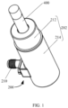
FIG. 1 is a first schematic view of an aerosol generating apparatus according to an embodiment of the present application (in a use state); -
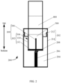
FIG. 2 is a second schematic view of the aerosol generating apparatus according to an embodiment of the present application (in a use state); -
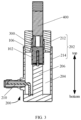
FIG. 3 is a cross-sectional view of the aerosol generating apparatus according to an embodiment of the present application (in a use state); -
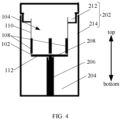
FIG. 4 is a first schematic view of a positional relationship of an aerosol fixing apparatus in the aerosol generating apparatus according to an embodiment of the present application; -
FIG. 5 is a second schematic view of a positional relationship of the aerosol fixing apparatus in the aerosol generating apparatus according to an embodiment of the present application; -
FIG. 6 is a third schematic view of a positional relationship of the aerosol fixing apparatus in the aerosol generating apparatus according to an embodiment of the present application; -
FIG. 7 is a fourth schematic view of a positional relationship of the aerosol fixing apparatus in the aerosol generating apparatus according to an embodiment of the present application; and -
FIG. 8 is a top view of the aerosol generating apparatus according to an embodiment of the present application. - Correspondences between reference signs and component names in
FIG. 1 to FIG. 8 are provided as follows: - 100: aerosol fixing apparatus, 102: mounting seat, 104: atomizing cavity, 106: microwave introduction structure, 108: conductor member, 110: side wall, 112: bottom wall, 200: aerosol generating apparatus, 202: housing, 204: resonant cavity, 206: resonant column, 208: mounting groove, 210: microwave feeding structure, 212: cover, 214: cavity, 300: aerosol generating substrate, 400: mounting rod, 402: ventilation opening.
- To understand the above objectives, features, and advantages of the present application more clearly, the present application will be further described in detail below with reference to accompanying drawings and specific implementations. It should be noted that embodiment of the present application and the features in the embodiments may be combined with each other without conflict.
- In the following description, numerous specific details are set forth in order to provide a thorough understanding of the present application. However, the present application may be practiced in other manners other than those described herein. Therefore, the protection scope of the present application is not limited to specific embodiments disclosed below.
- An
aerosol fixing apparatus 100 and anaerosol generating apparatus 200 provided according to some embodiments of the present application are described below with reference toFIG. 1 to FIG. 8 . - A first embodiment of the present application provides an
aerosol fixing apparatus 100, which includes a mountingseat 102, amicrowave introduction structure 106, and aconductor member 108. - As shown in
FIG. 1 ,FIG. 2 , andFIG. 3 , the mountingseat 102 includes anatomizing cavity 104. Theatomizing cavity 104 may be configured to mount and fix anaerosol generating substrate 300. Specifically, at least a part of theaerosol generating substrate 300 located in theatomizing cavity 104 can generate aerosol when heated. In addition, themicrowave introduction structure 106 is disposed on the mountingseat 102, and an output end of themicrowave introduction structure 106 is located inside theatomizing cavity 104. Themicrowave introduction structure 106 may be configured to introduce microwaves into theatomizing cavity 104, so as to heat theaerosol generating substrate 300 inside theatomizing cavity 104. Moreover, heating theaerosol generating substrate 300 by microwaves can achieve rapid and efficient heating of theaerosol generating substrate 300, thereby improving generation efficiency and a generation speed of aerosol. - In particular, during the generation of aerosol, magnetic field intensity is strongest at the output end of the
microwave introduction structure 106, and magnetic field intensity at other positions is weaker. Therefore, as shown inFIG. 4 andFIG. 5 , in the present application, aconductor member 108 is disposed on the mountingseat 102, and at least a part of theconductor member 108 is ensured to be disposed on aside wall 110 of theatomizing cavity 104. In this way, according to the present application, magnetic field distribution in theatomizing cavity 104 can be changed by theconductor member 108, thereby achieving uniform heating of theaerosol generating substrate 300 in theatomizing cavity 104. - Specifically, during the generation of aerosol, there is a strong electromagnetic field adjacent to the output end of the
microwave introduction structure 106, essence of interaction between microwaves and different substances is direct interaction between a microwave electromagnetic field and materials, and a high-frequency alternating electric field causes repeated polarization and violent movement of free or bound charges inside metal materials, which results in collision, friction, and internal friction between molecules, ultimately converting microwave energy into thermal energy. - Therefore, as shown in
FIG. 4 andFIG. 5 , in the present application, theconductor member 108 is disposed on the mountingseat 102. Theconductor member 108 is a good conductor, during microwave heating, an eddy current in a surface layer of theconductor member 108 may be concentrated on a surface of theconductor member 108 by skin effect, resulting in coupling with microwaves. Theconductor member 108 can convert microwave energy into thermal energy, which can further effectively heat theaerosol generating substrate 300 and ensure effective and uniform heating of the entireaerosol generating substrate 300. - Therefore, as shown in
FIG. 4 andFIG. 5 , in this embodiment, theconductor member 108 is disposed on the mountingseat 102, and at least a part of theconductor member 108 is located on theside wall 110 of theatomizing cavity 104, such that a magnetic field distribution intensity in theatomizing cavity 104 is changed by theconductor member 108. One the one hand, an efficient heating of theaerosol generating substrate 300 by microwaves can be ensured, on the other hand, uniform heating of theaerosol generating substrate 300 by microwaves can be ensured. - Specifically, as shown in
FIG. 1 ,FIG. 2 , andFIG. 3 , during use, theaerosol generating substrate 300 is provided inside the mountingrod 400 and is inserted into theatomizing cavity 104 through the mountingrod 400. - A second embodiment of the present application provides an
aerosol fixing apparatus 100. On the basis of the first embodiment, further. - As shown in
FIG. 4 andFIG. 5 , a top of theatomizing cavity 104 is provided with an opening end, and theaerosol generating substrate 300 can be inserted into theatomizing cavity 104 from the opening end. - In this embodiment, the
conductor member 108 extends along a height direction of theatomizing cavity 104, such that an extension direction of theconductor member 108 is the same as an insertion direction of theaerosol generating substrate 300. In this way, during the generation of aerosol, the magnetic field distribution intensity in theatomizing cavity 104 can be changed by theconductor member 108, and even distribution of the magnetic field in the height direction of theatomizing cavity 104 can be ensured, thereby achieving uniform and efficient heating of theaerosol generating substrate 300 in the height direction of theatomizing cavity 104. - In this embodiment, further, as shown in
FIG. 4 andFIG. 5 , one end of theconductor member 108 is disposed on abottom wall 112 of theatomizing cavity 104, and the other end of theconductor member 108 extends towards the opening end at the top of theatomizing cavity 104. In addition, in the height direction of theatomizing cavity 104, a ratio of a dimension of theconductor member 108 to a dimension of theaerosol generating substrate 300 is less than or equal to 1/3. - In this way, the dimension of the
conductor member 108 is reasonably configured in the height direction of theatomizing cavity 104, such that the magnetic field intensity distribution in theatomizing cavity 104 is more reasonable, thereby improving uniform and efficient heating of theaerosol generating substrate 300 in the height direction of theatomizing cavity 104 by microwaves. In addition, in the height direction of theatomizing cavity 104, a minimum ratio of the dimension of theconductor member 108 to the dimension of theaerosol generating substrate 300 may be designed according to an actual requirement, which is not limited herein. - A third embodiment of the present application provides an
aerosol fixing apparatus 100. On the basis of the first embodiment, further. - As shown in
FIG. 4 andFIG. 5 , at least twoconductor members 108 are provided. The at least twoconductor members 108 are distributed along a peripheral side of theatomizing cavity 104. Specifically, the at least twoconductor members 108 are evenly distributed along the peripheral side of theatomizing cavity 104. In particular, during the generation of aerosol, eachconductor member 108 may heat theaerosol generating substrate 300. - Therefore, in this embodiment, the at least two
conductor members 108 are distributed along the peripheral side of theatomizing cavity 104 to ensure uniform and efficient heating of theaerosol generating substrate 300 on the peripheral side of theatomizing cavity 104 by microwaves. - Specifically, the number of the
conductor members 108 can be 2 to 10, preferably 2 to 4. - A fourth embodiment of the present application proposes an
aerosol fixing apparatus 100. On the basis of the first embodiment, further. - As shown in
FIG. 4 andFIG. 5 , theconductor member 108 may be disposed on an inner wall of theatomizing cavity 104, or an outer wall of theatomizing cavity 104, or may alternatively be disposed on both the inner wall and the outer wall of theatomizing cavity 104. - Specifically, a specific position of the
conductor member 108 may be designed according to an actual situation. For example, the position may be designed according to a volume of theatomizing cavity 104. When the volume of theatomizing cavity 104 is small, theconductor member 108 may be disposed on the outer wall of theatomizing cavity 104 to prevent further occupation of space in theatomizing cavity 104 by theconductor member 108. When the volume of theatomizing cavity 104 is large, theconductor member 108 may be disposed on the inner wall of theatomizing cavity 104 to efficiently heat theaerosol generating substrate 300 directly by theconductor member 108. - On the basis of the first embodiment to the fourth embodiment, further, as shown in
FIG. 4 , theconductor member 108 includes a metal strip. The metal strip is distributed in a strip shape on theside wall 110 of theatomizing cavity 104 and extends from thebottom wall 112 of theatomizing cavity 104 to the opening end at the top of theatomizing cavity 104. In particular, the metal strip is a good conductor, and the magnetic field distribution in theatomizing cavity 104 may be changed, which on the one hand can ensure efficient heating of theaerosol generating substrate 300 by microwaves, on the other hand it can ensure uniform heating of theaerosol generating substrate 300 by microwaves. - In addition, in the height direction of the
atomizing cavity 104, a ratio of a dimension of the metal strip to the dimension of theaerosol generating substrate 300 is less than or equal to 1/3. Moreover, theconductor member 108 includes at least two metal strips, and the at least two metal strips are distributed at intervals along the peripheral side of theatomizing cavity 104. - On the basis of the first embodiment to the fourth embodiment, further, as shown in
FIG. 5 , theconductor member 108 includes a metal coil. The metal coil is distributed in a spiral shape on theside wall 110 of theatomizing cavity 104 and extends from thebottom wall 112 of theatomizing cavity 104 to the opening end at the top of theatomizing cavity 104. In particular, the metal coil is a good conductor, and the magnetic field distribution in theatomizing cavity 104 may be changed, which can on the one hand ensure efficient heating of theaerosol generating substrate 300 by microwaves, on the other hand it can ensure uniform heating of theaerosol generating substrate 300 by microwaves. - In addition, in the height direction of the
atomizing cavity 104, a ratio of a dimension of the metal coil to the dimension of theaerosol generating substrate 300 is less than or equal to 1/3. Moreover, theconductor member 108 includes at least two metal coils, and the at least two metal coils are distributed at intervals along the peripheral side of theatomizing cavity 104. Moreover, in the height direction of theatomizing cavity 104, distances between adjacent two spiral coils are equal. - On the basis of the first embodiment to the fourth embodiment, further, the
conductor member 108 includes a first metal layer (not shown). The first metal layer is distributed on theside wall 110 of theatomizing cavity 104 and extends from thebottom wall 112 of theatomizing cavity 104 to the opening end at the top of theatomizing cavity 104. In addition, the first metal layer may be provided with the hollow area, thereby further adjusting the magnetic field distribution in theatomizing cavity 104. In particular, the first metal layer is a good conductor, and the magnetic field distribution in theatomizing cavity 104 may be changed, which on the one hand can ensure efficient heating of theaerosol generating substrate 300 by microwaves, on the other hand it can ensure uniform heating of theaerosol generating substrate 300 by microwaves. - In addition, in the height direction of the
atomizing cavity 104, a ratio of a dimension of the first metal layer to the dimension of theaerosol generating substrate 300 is less than or equal to 1/3. - On the basis of the first embodiment to the fourth embodiment, further, an inner wall of the
atomizing cavity 104 is provided with a convex portion (not shown). The convex portion may be disposed on an inner side wall of theatomizing cavity 104 and be in contact with theaerosol generating substrate 300 during operation. In this way, during the generation of aerosol, there is a certain discharge between theaerosol generating substrate 300 and the inner wall of theatomizing cavity 104, which facilitates the aerosol generated in theatomizing cavity 104 to be smoothly discharged from theatomizing cavity 104 through the gap. - On the basis of the first embodiment to the fourth embodiment, further, as shown in
FIG. 2 andFIG. 3 , themicrowave introduction structure 106 extends through thebottom wall 112 of theatomizing cavity 104. An input end of themicrowave introduction structure 106 is located outside theatomizing cavity 104, and an output end of themicrowave introduction structure 106 is located inside theatomizing cavity 104. In this way, during use, themicrowave introduction structure 106 can introduce external microwaves into theatomizing cavity 104, so as to heat theaerosol generating substrate 300 in theatomizing cavity 104. Specifically, themicrowave introduction structure 106 is disposed at a central position of thebottom wall 112 of theatomizing cavity 104. - On the basis of the first embodiment to the fourth embodiment, further, as shown in
FIG. 2 andFIG. 3 , themicrowave introduction structure 106 and the mountingseat 102 are integrally formed. In this way, on the one hand, no connecting members are required to connect themicrowave introduction structure 106 and the mountingseat 102, and on the other hand, the connection strength between themicrowave introduction structure 106 and the mountingseat 102 is also ensured, thereby prolonging a service life of theaerosol fixing apparatus 100. - Specifically, the
microwave introduction structure 106 and the mountingseat 102 are tightly connected without any gap. - On the basis of the first embodiment to the fourth embodiment, further, as shown in
FIG. 3 , in the height direction of theatomizing cavity 104, a dimension of a part of themicrowave introduction structure 106 located in theatomizing cavity 104 is less than a dimension of theaerosol generating substrate 300. - In this way, during use, after the
aerosol generating substrate 300 is inserted into theatomizing cavity 104, it is ensured that the output end of themicrowave introduction structure 106 is inserted into theaerosol generating substrate 300, and the output end of themicrowave introduction structure 106 may not expose theaerosol generating substrate 300. In this way, an internal position of theaerosol generating substrate 300 can be heated by the output end of themicrowave introduction structure 106. - Further, as shown in
FIG. 3 , the output end of themicrowave introduction structure 106 is located inside theaerosol generating substrate 300, so as to heat the internal position of theaerosol generating substrate 300. Theconductor member 108 is located outside theaerosol generating substrate 300 and at the peripheral side of theaerosol generating substrate 300, so as to heat the peripheral side of theaerosol generating substrate 300. In this way, through the cooperation between themicrowave introduction structure 106 and theconductor member 108, comprehensive heating of theaerosol generating substrate 300 can be achieved, thus ensuring heating efficiency and heating uniformity of theaerosol generating substrate 300. - Specifically, a size of a part of the
microwave introduction structure 106 located in theatomizing cavity 104 may be 5 mm to 25 mm, preferably 12 mm to 13 mm. - In addition, the
microwave introduction structure 106 may be a metal structure or other high-conductivity structures, preferably the metal structure (such as copper, aluminum, or stainless steel). Alternatively, a metal film layer (such as gold-plated, silver-plated, or copper-plated) may be plated on an outer surface of a non-metal structure. - On the basis of the first embodiment to the fourth embodiment, further, the mounting
seat 102 is a non-conductive mountingseat 102. Specifically, the mountingseat 102 is made of a non-conductive material with a low dielectric loss, such as a PEEK material, PTFE, microwave transparent ceramics, glass, silicon carbide, or aluminum oxide. - On the basis of the first embodiment to the fourth embodiment, further, as shown in
FIG. 2 andFIG. 3 , themicrowave introduction structure 106 is a probe or a conductive sheet. Themicrowave introduction structure 106 may be a metal (copper, aluminum, or stainless steel) introduction structure, or a non-metal introduction structure, and a fourth metal layer (such as gold-plated, silver-plated, or copper plated) is provided on an outer surface of the non-metal introduction structure. - On the basis of the first embodiment to the fourth embodiment, further, as shown in
FIG. 2 andFIG. 3 , theatomizing cavity 104 is acylindrical cavity 214, and an inner diameter of theatomizing cavity 104 is equal to or slightly greater than a diameter of theaerosol generating substrate 300. Specifically, a diameter of theatomizing cavity 104 may be 5 mm to 20 mm, preferably 6.5 mm to 7.5 mm. In addition. - On the basis of the first embodiment to the fourth embodiment, further, the
conductor member 108 may be made of a metal material (such as copper, aluminum, or stainless steel) or other high-conductivity materials. - During use, the
aerosol generating substrate 300 is mounted in the mountingrod 400. - In addition, as shown in
FIG. 6 andFIG. 7 , in the present application, theaerosol fixing apparatus 100 and theaerosol generating substrate 300 may alternatively be provided as an integrated structure, and are a closed component as a whole. In this way, a cleaning-free operation can be realized, and theaerosol generating substrate 300 can be replaced with a new one after each use. In this case, the mountingrod 400 configured to mount theaerosol generating substrate 300 is provided with aventilation opening 402, so as to ensure flowing out of the generated aerosol. - As shown in
FIG. 1 andFIG. 8 , a fifth embodiment of the present application provides anaerosol generating apparatus 200, which includes theaerosol fixing apparatus 100 as described in any one of the above embodiments, and therefore has all the beneficial effects of theaerosol fixing apparatus 100. Details are not described herein again. - In addition, as shown in
FIG. 1 andFIG. 8 , theaerosol generating apparatus 200 further includes ahousing 202, a microwave assembly, and aresonant column 206. As shown inFIG. 1 ,FIG. 2 , andFIG. 3 , thehousing 202 is provided with aresonant cavity 204 therein. The microwave assembly may be disposed on thehousing 202 and may feed microwaves into theresonant cavity 204 during operation. Theresonant column 206 is disposed in theresonant cavity 204, and a first end of theresonant column 206 is connected to a cavity bottom wall of theresonant cavity 204. After theaerosol fixing apparatus 100 is mounted, at least a part of theaerosol fixing apparatus 100 is disposed in theresonant cavity 204, and the input end of themicrowave introduction structure 106 is connected to a second end of theresonant column 206. In this way, it is ensured that theaerosol generating substrate 300 in theatomizing cavity 104 can be heated by the microwaves fed into theresonant cavity 204. - A sixth embodiment of the present application provides an
aerosol generating apparatus 200. On the basis of the fifth embodiment, further. - As shown in
FIG. 2 ,FIG. 4 , andFIG. 5 , theaerosol generating apparatus 200 further includes a mountinggroove 208. The mountinggroove 208 is disposed at the second end of theresonant column 206 and is configured according to theresonant column 206. When mounting theaerosol fixing apparatus 100, at least a part of theaerosol fixing apparatus 100 is located in theresonant cavity 204, and an introduction end of themicrowave introduction structure 106 extends into the mountinggroove 208, which on the one hand ensures a mounting manner of theaerosol fixing apparatus 100, and on the other hand a conductive connection between themicrowave introduction structure 106 and theresonant column 206 is ensured. - Specifically, the mounting
groove 208 allows theconductor member 108 protruding from the bottom of the mountingseat 102 to be inserted and pulled out multiple times. The mountinggroove 208 is in close contact with and tightly clamped with theconductor member 108 to achieve conductive communication. - In this embodiment, further, as shown in
FIG. 2 ,FIG. 4 , andFIG. 5 , in the height direction of theaerosol generating apparatus 200, a dimension of a part of the mountingseat 102 located in theresonant cavity 204 is greater than or equal to a dimension of theaerosol generating substrate 300. In this way, during use, theaerosol generating substrate 300 can be ensured to be completely inside the mountingseat 102, and theaerosol generating substrate 300 can be ensured to be completely inside theresonant cavity 204. - Specifically, the dimension of the part of the mounting
seat 102 located in theresonant cavity 204 may be 5 mm to 25 mm, preferably 12 mm to 13 mm. - On the basis of the fifth embodiment and the sixth embodiment, further, as shown in
FIG. 1 ,FIG. 3 , andFIG. 8 , the microwave assembly includes amicrowave feeding structure 210 and a microwave emission source (not shown). Themicrowave feeding structure 210 is disposed on thehousing 202, an output end of themicrowave feeding structure 210 faces a bottom wall of theresonant cavity 204 or theresonant column 206, and an input end of themicrowave feeding structure 210 is connected to the microwave emission source. In this way, when theaerosol generating apparatus 200 works, microwaves generated by the microwave emission source are fed into theresonant cavity 204 through themicrowave feeding structure 210. - Specifically, the
resonant column 206 can act as a conductor, and theresonant column 206 may be made of a metal material. Exemplarily, theresonant column 206 is made of copper, aluminum, iron, or alloys thereof. Theresonant column 206 is configured to transmit microwaves and increase a microwave transmission rate. The microwaves are not prone to attenuation when conducted in theresonant cavity 204. - On the basis of the fifth embodiment and the sixth embodiment, further, the
housing 202 may be a metal housing. In addition, thehousing 202 may alternatively be a non-metal housing, and an inner wall of thehousing 202 is provided with a second metal layer. - Specifically, an inner wall of the
resonant cavity 204 is electric conductive, and thehousing 202 may be made of a conductive material, preferably metal (such as copper, aluminum, or stainless steel), or a conductive coating (such as gold-plated, silver-plated, or copper plated) may be provided on the inner wall of thehousing 202. - Specifically, as shown in
FIG. 1 ,FIG. 2 , andFIG. 3 , thehousing 202 includes acylindrical cavity 214 and acover 212. An inner wall of thecavity 214 is electric conductive, and thecover 212 is a plastic product with high mechanical strength, such as polycarbonate (PC) or polylactic acid (PLA). - On the basis of the fifth embodiment and the sixth embodiment, further, the
resonant column 206 may be a conductor column. In addition, theresonant column 206 may alternatively be a non-conductor column, and an outer wall of theresonant column 206 is provided with a third metal layer. - Specifically, the conductor column is a hollow or solid structure, and the outer wall thereof is conductive. The conductor column may be made of a metal material or other high-conductivity materials, preferably metal (such as copper, aluminum, or stainless steel), or a metal film layer (such as gold-plated, silver-plated, or copper-plated) may be plated on an outer surface of a non-metal structure.
- On the basis of the fifth embodiment and the sixth embodiment, further, the
resonant column 206 is conductively connected to thehousing 202. - Therefore, in the present application, the
conductor member 108 is disposed around theside wall 110 of theatomizing cavity 104, and theconductor member 108 is not conductively connected to theresonant column 206, and then microwave field distribution is changed by theconductor member 108, such that theaerosol generating substrate 300 can be heated more uniformly as a whole. Moreover, after theaerosol fixing apparatus 100 is inserted and electrically connected to a top end of theresonant column 206, a strong electromagnetic field may exist adjacent to the top end of themicrowave introduction structure 106, such that middle and upper sections of theaerosol generating substrate 300 are rapidly heated and atomized. Further, themicrowave introduction structure 106 and the mountingseat 102 are tightly connected without any gap, the aerosol generated when theaerosol generating substrate 300 is heated will not pollute an internal structure of theresonant cavity 204, and there is only a need to wipe an internal structure of theaerosol fixing apparatus 100, which is easy to clean. Moreover, themicrowave introduction structure 106 and the mountingseat 102 adopt an integrated design, when themicrowave introduction structure 106 is accidentally damaged, the mountingseat 102 can be replaced, which may not affect a normal heating effect of theaerosol generating apparatus 200 on theaerosol generating substrate 300, and is easy to operate and low-cost, helping maintain theresonant cavity 204 and prolonging a service life of theaerosol generating apparatus 200. - In the description of the present application, the term "a plurality of" indicates two or more, unless otherwise expressly defined. The orientation or position relationship indicated by the terms "above," "below," and the like is based on the orientation or position relationship shown in the drawing, is only for the convenience of describing the embodiments of the present application and for the simplicity of the descriptions, and does not indicate or imply that the apparatus or element referred to must include a specific orientation, or be configured or operated with a specific orientation, and therefore cannot be understood as limiting the present application. The terms "connect", "mount", "fix", and the like should be understood in a broad sense. For example, "connect" may be a fixed connection, a detachable connection, or an integrated connection; or a direct connection, or an indirect connection via an intermediate medium. Those of ordinary skill in the art would understand specific meanings of these terms in the present application based on specific situations.
- In the description of this specification, the description of the terms "an embodiment", "some embodiments", "specific embodiments", and the like means that specific features, structures, materials, or characteristics described with reference to the embodiment(s) or example(s) are included in at least one embodiment or example of the present application. In this specification, a schematic representation of the foregoing terms does not necessarily refer to a same embodiment or a same example. In addition, the described specific features, structures, materials, or characteristics may be combined in one or more embodiments or examples in an appropriate manner.
- The foregoing descriptions are only preferred embodiments of the present application, and not intended to limit the present application. For those skilled in the art, the present application may have various changes and variations. Any modifications, equivalent replacements, improvements, and the like made within the spirit and principle of the present application shall fall within the protection scope of the present application.
Claims (15)
- An aerosol fixing apparatus, comprising:a mounting seat comprising an atomizing cavity, the atomizing cavity being configured to place an aerosol generating substrate;a microwave introduction structure disposed on the mounting seat, an output end of the microwave introduction structure being located in the atomizing cavity; anda conductor member disposed on the mounting seat, and at least a part of the conductor member being located on a side wall of the atomizing cavity.
- The aerosol fixing apparatus according to claim 1, wherein the conductor member extends in a height direction of the atomizing cavity.
- The aerosol fixing apparatus according to claim 2, wherein one end of the conductor member is disposed on a bottom wall of the atomizing cavity; and in the height direction of the atomizing cavity, a ratio of a dimension of the conductor member to a dimension of the aerosol generating substrate is less than or equal to 1/3.
- The aerosol fixing apparatus according to any one of claims 1 to 3, wherein at least two conductor members are provided, and the at least two conductor members are distributed along a peripheral side of the atomizing cavity.
- The aerosol fixing apparatus according to any one of claims 1 to 3, wherein the conductor member is disposed on an inner wall of the atomizing cavity; and/or
the conductor member is disposed on an outer wall of the atomizing cavity. - The aerosol fixing apparatus according to any one of claims 1 to 3, wherein the conductor member comprises:
a metal strip distributed in a strip shape on the side wall of the atomizing cavity and extending towards a top of the atomizing cavity. - The aerosol fixing apparatus according to any one of claims 1 to 3, wherein the conductor member comprises:
a metal coil distributed in a spiral shape on the side wall of the atomizing cavity and extending towards a top of the atomizing cavity. - The aerosol fixing apparatus according to any one of claims 1 to 3, wherein the conductor member comprises:
a first metal layer disposed on the side wall of the atomizing cavity, and at least a part of the first metal layer being provided with a hollow area. - The aerosol fixing apparatus according to any one of claims 1 to 3, wherein an inner wall of the atomizing cavity is provided with a convex portion.
- The aerosol fixing apparatus according to any one of claims 1 to 3, wherein the microwave introduction structure extends through a bottom wall of the atomizing cavity; and/orthe microwave introduction structure and the mounting seat are integrally formed; and/orin a height direction of the atomizing cavity, a dimension of a part of the microwave introduction structure located in the atomizing cavity is less than a dimension of the aerosol generating substrate.
- An aerosol generating apparatus, comprising:a housing provided with a resonant cavity;a microwave assembly disposed on the housing, the microwave assembly being configured to feed microwave into the resonant cavity;a resonant column, a first end of the resonant column being connected to a cavity bottom wall of the resonant cavity; andthe aerosol fixing apparatus according to any one of claims 1 to 10, at least a part of the aerosol fixing apparatus being disposed in the resonant cavity, and an input end of the microwave introduction structure being connected to a second end of the resonant column.
- The aerosol generating apparatus according to claim 11, further comprising:
a mounting groove disposed at the second end of the resonant column, and the input end of the microwave introduction structure being connected to the mounting groove. - The aerosol generating apparatus according to claim 11, further comprising: in a height direction of the aerosol generating apparatus, a dimension of a part of the mounting seat located in the resonant cavity is greater than or equal to a dimension of the aerosol generating substrate.
- The aerosol generating apparatus according to any one of claims 11 to 13, wherein the microwave assembly comprises:a microwave feeding structure disposed on the housing, an output end of the microwave feeding structure facing a bottom wall of the resonant cavity or the resonant column; anda microwave emission source connected to an input end of the microwave feeding structure.
- The aerosol generating apparatus according to any one of claims 11 to 13, wherein the housing is a metal housing, or an inner wall of the housing is provided with a second metal layer; and/or
the resonant column is a conductor column, or an outer wall of the resonant column is provided with a third metal layer.
Applications Claiming Priority (3)
| Application Number | Priority Date | Filing Date | Title |
|---|---|---|---|
| CN202111219813.6A CN115989895A (en) | 2021-10-20 | 2021-10-20 | Aerosol fixing device and aerosol generating device |
| CN202122524208.1U CN216165164U (en) | 2021-10-20 | 2021-10-20 | Aerosol fixing device and aerosol generating device |
| PCT/CN2022/120304 WO2023065946A1 (en) | 2021-10-20 | 2022-09-21 | Aerosol fixing apparatus and aerosol generating apparatus |
Publications (2)
| Publication Number | Publication Date |
|---|---|
| EP4417071A1 true EP4417071A1 (en) | 2024-08-21 |
| EP4417071A4 EP4417071A4 (en) | 2025-02-19 |
Family
ID=86058801
Family Applications (1)
| Application Number | Title | Priority Date | Filing Date |
|---|---|---|---|
| EP22882557.6A Pending EP4417071A4 (en) | 2021-10-20 | 2022-09-21 | AEROSOL ATTACHMENT APPARATUS AND AEROSOL GENERATING APPARATUS |
Country Status (4)
| Country | Link |
|---|---|
| EP (1) | EP4417071A4 (en) |
| JP (1) | JP2024536571A (en) |
| KR (1) | KR20240093721A (en) |
| WO (1) | WO2023065946A1 (en) |
Cited By (1)
| Publication number | Priority date | Publication date | Assignee | Title |
|---|---|---|---|---|
| EP4497336A4 (en) * | 2022-03-23 | 2025-06-18 | Shenzhen Merit Technology Co., Ltd. | AEROSOL GENERATING DEVICE AND MANUFACTURING METHOD THEREFOR |
Families Citing this family (1)
| Publication number | Priority date | Publication date | Assignee | Title |
|---|---|---|---|---|
| WO2025163881A1 (en) * | 2024-02-02 | 2025-08-07 | 日本たばこ産業株式会社 | Smoking system and method for producing electrode |
Family Cites Families (20)
| Publication number | Priority date | Publication date | Assignee | Title |
|---|---|---|---|---|
| US10104912B2 (en) * | 2016-01-20 | 2018-10-23 | Rai Strategic Holdings, Inc. | Control for an induction-based aerosol delivery device |
| CN109688850B (en) * | 2016-09-14 | 2022-01-11 | 菲利普莫里斯生产公司 | Aerosol-generating system and method for controlling an aerosol-generating system |
| US10524508B2 (en) * | 2016-11-15 | 2020-01-07 | Rai Strategic Holdings, Inc. | Induction-based aerosol delivery device |
| US11197497B2 (en) * | 2017-04-11 | 2021-12-14 | Kt&G Corporation | Aerosol generating device |
| CN110859321B (en) * | 2018-08-08 | 2024-08-20 | 北京航天雷特机电工程有限公司 | A cigarette cartridge and electronic cigarette |
| CN110859323B (en) * | 2018-08-08 | 2024-11-29 | 北京航天雷特机电工程有限公司 | Microwave cavity and electronic cigarette |
| PT3747289T (en) * | 2019-06-06 | 2022-04-21 | Nvx Labs Gmbh | MICROWAVE HEATING UNIT AND METHOD |
| KR102389832B1 (en) * | 2019-06-18 | 2022-04-22 | 주식회사 케이티앤지 | Apparatus for generating aerosol by using microwave and method thereof |
| CN110279150A (en) * | 2019-06-19 | 2019-09-27 | 云南巴菰生物科技有限公司 | A kind of outer conductor heating chamber for microwave heating not combustion apparatus |
| CN110279152B (en) * | 2019-06-19 | 2022-05-10 | 云南巴菰生物科技股份有限公司 | Microwave electronic cigarette |
| CN110279151A (en) * | 2019-06-19 | 2019-09-27 | 云南巴菰生物科技有限公司 | A kind of microwave heating is not burnt smoking set |
| CN210143835U (en) * | 2019-06-19 | 2020-03-17 | 云南巴菰生物科技有限公司 | Coaxial heating chamber and electronic cigarette device with same |
| CN110141002A (en) * | 2019-06-19 | 2019-08-20 | 云南巴菰生物科技有限公司 | A coaxial heating cavity and an electronic cigarette device with the coaxial heating cavity |
| CN112137167B (en) * | 2019-06-28 | 2024-08-20 | 北京航天雷特机电工程有限公司 | Microwave antenna and electronic cigarette |
| KR102795090B1 (en) * | 2019-07-25 | 2025-04-15 | 한국전기연구원 | Microwave-frequency induction heating apparatus |
| CN110652038B (en) * | 2019-09-02 | 2025-04-11 | 成都亚彦科技有限公司 | Non-combustion smoking accessories and products |
| KR20210071459A (en) * | 2019-12-06 | 2021-06-16 | 주식회사 이노아이티 | Microwave heating device |
| CN112056625B (en) * | 2020-08-25 | 2025-01-24 | 泰新半导体(贵州)有限公司 | Small structure non-fully enclosed electromagnetic energy converter and electronic cigarette |
| CN113180307B (en) * | 2021-04-28 | 2023-05-16 | 北京航天雷特机电工程有限公司 | Microwave antenna and electronic cigarette |
| CN216165164U (en) * | 2021-10-20 | 2022-04-05 | 深圳麦克韦尔科技有限公司 | Aerosol fixing device and aerosol generating device |
-
2022
- 2022-09-21 JP JP2024523516A patent/JP2024536571A/en active Pending
- 2022-09-21 WO PCT/CN2022/120304 patent/WO2023065946A1/en not_active Ceased
- 2022-09-21 KR KR1020247016321A patent/KR20240093721A/en active Pending
- 2022-09-21 EP EP22882557.6A patent/EP4417071A4/en active Pending
Cited By (1)
| Publication number | Priority date | Publication date | Assignee | Title |
|---|---|---|---|---|
| EP4497336A4 (en) * | 2022-03-23 | 2025-06-18 | Shenzhen Merit Technology Co., Ltd. | AEROSOL GENERATING DEVICE AND MANUFACTURING METHOD THEREFOR |
Also Published As
| Publication number | Publication date |
|---|---|
| EP4417071A4 (en) | 2025-02-19 |
| KR20240093721A (en) | 2024-06-24 |
| JP2024536571A (en) | 2024-10-04 |
| WO2023065946A1 (en) | 2023-04-27 |
Similar Documents
| Publication | Publication Date | Title |
|---|---|---|
| CN216165164U (en) | Aerosol fixing device and aerosol generating device | |
| EP4449911A1 (en) | Microwave heating assembly, and aerosol generation device and aerosol generating system | |
| JP4694596B2 (en) | Microwave plasma processing apparatus and microwave power feeding method | |
| CN105392227B (en) | It is a kind of using micro-wave oven of the spiral antenna with circular polarization as radiator | |
| WO2023065946A1 (en) | Aerosol fixing apparatus and aerosol generating apparatus | |
| KR101004366B1 (en) | Microwave plasma processing device and microwave feeding method | |
| CN105357790A (en) | Double-tube microwave oven adopting circularly polarized helical antennae as radiators | |
| CN108353471B (en) | Microwave oven with a heat exchanger | |
| CN115989895A (en) | Aerosol fixing device and aerosol generating device | |
| EP3121519B1 (en) | Connection structure and input/output connection structure of semiconductor microwave generator for microwave oven, and microwave oven | |
| EP2887378B1 (en) | Magnetron and high-frequency heating apparatus having the same | |
| EP4616731A1 (en) | Aerosol generation device and microwave heating assembly therefor | |
| JP3925153B2 (en) | Magnetron | |
| CA2803586C (en) | Microwave driven plasma light source | |
| KR100955269B1 (en) | Sludge dryer with high efficiency using micro wave | |
| CN110379692B (en) | Flattened magnetron for microwave oven adopting symmetrical magnetic circuit | |
| CN110191530A (en) | A microwave radiation heating device | |
| CN118058509A (en) | Aerosol Generating Device | |
| CN117981914A (en) | Aerosol generating device and microwave heating component thereof | |
| US9236214B2 (en) | Electron tube | |
| CN117617587A (en) | Microwave heater and aerosol generating device | |
| US12267937B2 (en) | Transfer connector with improved operational reliability | |
| CN116826339B (en) | Coaxial waveguide converter, microwave equipment and communication equipment | |
| CN110113833A (en) | A kind of microwave radiation heating antenna component | |
| CN221508476U (en) | Radio frequency antenna and cooking equipment |
Legal Events
| Date | Code | Title | Description |
|---|---|---|---|
| STAA | Information on the status of an ep patent application or granted ep patent |
Free format text: STATUS: THE INTERNATIONAL PUBLICATION HAS BEEN MADE |
|
| PUAI | Public reference made under article 153(3) epc to a published international application that has entered the european phase |
Free format text: ORIGINAL CODE: 0009012 |
|
| STAA | Information on the status of an ep patent application or granted ep patent |
Free format text: STATUS: REQUEST FOR EXAMINATION WAS MADE |
|
| 17P | Request for examination filed |
Effective date: 20240516 |
|
| AK | Designated contracting states |
Kind code of ref document: A1 Designated state(s): AL AT BE BG CH CY CZ DE DK EE ES FI FR GB GR HR HU IE IS IT LI LT LU LV MC MK MT NL NO PL PT RO RS SE SI SK SM TR |
|
| RAP3 | Party data changed (applicant data changed or rights of an application transferred) |
Owner name: SHENZHEN MERIT TECHNOLOGY CO., LTD. Owner name: SHENZHEN SMOORE TECHNOLOGY LIMITED |
|
| DAV | Request for validation of the european patent (deleted) | ||
| DAX | Request for extension of the european patent (deleted) | ||
| A4 | Supplementary search report drawn up and despatched |
Effective date: 20250117 |
|
| RIC1 | Information provided on ipc code assigned before grant |
Ipc: A24F 40/20 20200101ALI20250113BHEP Ipc: A24F 40/46 20200101ALI20250113BHEP Ipc: A24F 40/40 20200101AFI20250113BHEP |
|
| RAP3 | Party data changed (applicant data changed or rights of an application transferred) |
Owner name: SHENZHEN MERIT TECHNOLOGY CO., LTD. Owner name: SHENZHEN SMOORE TECHNOLOGY LIMITED |