EP4417049A1 - Device for dispensing bait - Google Patents
Device for dispensing bait Download PDFInfo
- Publication number
- EP4417049A1 EP4417049A1 EP24157705.5A EP24157705A EP4417049A1 EP 4417049 A1 EP4417049 A1 EP 4417049A1 EP 24157705 A EP24157705 A EP 24157705A EP 4417049 A1 EP4417049 A1 EP 4417049A1
- Authority
- EP
- European Patent Office
- Prior art keywords
- segments
- bait
- dispensing device
- container
- bait dispensing
- Prior art date
- Legal status (The legal status is an assumption and is not a legal conclusion. Google has not performed a legal analysis and makes no representation as to the accuracy of the status listed.)
- Pending
Links
Images



Classifications
-
- A—HUMAN NECESSITIES
- A01—AGRICULTURE; FORESTRY; ANIMAL HUSBANDRY; HUNTING; TRAPPING; FISHING
- A01K—ANIMAL HUSBANDRY; AVICULTURE; APICULTURE; PISCICULTURE; FISHING; REARING OR BREEDING ANIMALS, NOT OTHERWISE PROVIDED FOR; NEW BREEDS OF ANIMALS
- A01K97/00—Accessories for angling
- A01K97/02—Devices for laying ground-bait, e.g. chum dispensers, e.g. also for throwing ground-bait
Definitions
- the present invention relates to a device used for the dispensing of bait within a localised area of water.
- the invention relates to a bait dispensing device for use when fishing and is particularly suited to carp fishing.
- Sport fishing and particularly carp fishing is a recreational activity which requires a specific technique to effectively catch the Common Carp (Cyprinus Carpio) and the other members of family Cyprinidae. Given that carp do not possess teeth, they consume their food through the suction effect of their mouth. Therefore, the astute angler would not place the bait on a hook as this would be an ineffective technique for catching carp. Instead, the correct technique is to dispense the bait within a specified area of a body of water to attract the carp whilst the hook is then used to catch the carp by its lower lip.
- Common Carp Common Carp
- the correct technique is to dispense the bait within a specified area of a body of water to attract the carp whilst the hook is then used to catch the carp by its lower lip.
- bait dispensers Due to the need for effective and localised dispensing of bait, numerous devices, technically termed bait dispensers have been invented. These are devices which are used to contain bait whilst the device is cast into water and then proceed to dispense the bait within the water. This is with the intention of attracting bottom and surface-feeding fish.
- Carp-fishing requires that the bait dispenser only releases the bait in a specified area where the angler intends to place their hook. Therefore, it is crucial that the bait remains secure inside the bait dispenser when casting and the bait is only released upon contact with the water. Otherwise, the bait could be dispersed over a wide body of water which would dramatically reduce the effectiveness of the bait.
- WO2015/087361 describes a bait dispenser which consists of a container which is adapted to house bait within it whilst the bait dispenser is cast with a line and then once the bait dispenser impacts the water, the container then opens, due to the resultant shock wave effect, and dispenses the bait.
- the container of this device is comprised of two half-shells which are symmetrical in shape and possess a mutual joining plane.
- the container has a fastening means by which the container is connected to the line.
- This fastening means consists of two flexible threadlike elements which are identical in length. One end of each of the flexible threadlike elements is connected to its respective half-shell and the opposite end is connected to the other flexible threadlike element which is in turn connected to the other respective half-shell by its opposite end. The flexible threadlike elements are then simultaneously connected to the line.
- the container has a reversible closing means which uses the force of magnetic attraction between the two half-shells.
- WO2019/097558A1 describes a bait dispenser which consists of a container which is used to contain bait whilst the device is being cast.
- the container is subdivided into a plurality of at least four segments.
- This device allows the user to fill the container whilst a single segment is open.
- the device has a torpedo-like structure with a flat head at is distal end and a pointed proximal end.
- the device uses reversible closing means for its four segments which is generated by the magnetically attractive force of the magnets attached to each of the four segments which is then used to secure the four segments together when the container is closed.
- the four segments are adapted to remain connected through the magnetic attraction whilst the bait dispenser is being cast and then the four segments separate completely from one another when the bait dispenser is acted on by the shock wave effect of the water. Thus, the bait is released into the water.
- a first aspect of the present invention is directed to a bait dispensing device which can be filled with bait, and holds the bait secure when casting, dispersing the bait in a localised area upon contact with the water's surface, comprising:
- a second aspect of the present invention is directed to a bait dispensing device which can be filled with bait, and holds the bait secure when casting, dispersing the bait in a localised area upon contact with the water's surface, comprising:
- the bait dispensing device possesses a substantially flat face at its distal end and a pointed proximal tail which leads into stabilising fins, where the means of securing the container to the line are positioned at the proximal end of the bait dispensing device.
- the shape of the fins would facilitate the aerodynamics of the bait dispensing device and would produce a rotational motion upon descent.
- the container would have a 'bomb' shaped container but with a flat distal face.
- the bait is contained within the three segments when closed during the casting of the bait dispensing device and the three segments are secured together through the force of the active magnetic field between the magnets connected to each of the segments. Upon contact with the water's surface, the three segments separate from one another due to the shock wave upon impact with the water's surface. This then results in the bait being released into the water from within the container.
- the three segments would be made of a plastic flexible filiform material such as polypropylene which would provide a memory effect that would facilitate the bait dispensing device maintaining its open configuration during its retrieval.
- the three segments would all be identical in length so as to ensure even distribution of the force exerted on the container upon impact.
- the three segments would have interior or exterior ridged lips encompassing the edges of their interjoining edges which would provide a watertight seal when the bait dispensing device was in its closed configuration.
- the container of the bait dispensing device would comprise of three segments which each span a cross section of 120° of the container.
- the container of the bait dispensing device would comprise of one segment which spans a cross section of 180° of the container and two segments which each span 90° of the container.
- the bait dispensing device is equipped with a hinge mechanism which provides the advantage of a defined opening movement and a sturdy structural connection to increase longevity.
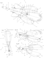
- Figure 1A and Figure 1B show a first bait dispensing device 10 from a front perspective view and rear perspective view respectively, comprising of a container 11, to hold bait within it whilst being cast with a line and the container 11 has a distal end 12 and a proximal end 13.
- the container 11 is comprised of three segments 14, 16, 18.
- the overall impression the container 11 gives when in its closed configuration is similar to that of a 'bomb-like' shape as shown in Figure 2 .
- the container 11 has a flat distal face 20.
- Each segment 14, 16, 18 widens from the flat distal face 20 for approximately 1 quarter of the length of the segment 14, 16, 18 before the segment 14, 16, 18 then becomes increasingly narrow until it reaches its proximal portion or proximal end 13.
- Each of the segments 14, 16, 18 is equipped with a stabilising fin 22 at their proximal portion 13 end.
- Each stabilising fin 22 is placed on the segment 14, 16, 18 such that it is spaced equidistant from the fin on another segment 14, 16, 18 around 360° of the central axis A of the bait dispensing device 10.
- the three segments 14, 16, 18 are permanently connected by a cylindrical fastening means 23 connecting to narrow flexible proximal tails 37 of the segments 14, 16, 18 at the proximal end of the stabilising fins 22.
- the segments 14, 16, 18 are joined to the fastening means by way of each segment's 14, 16, 18 respective narrow flexible proximal tail 37 being enclosed within the cylindrical fastening means 23.
- each segment's 14, 16, 18 respective stablishing fin 22 Between the cylindrical fastening means 23 and each segment's 14, 16, 18 respective stablishing fin 22, are a number of rectangular protrusions 24 which ensure that the segments 14, 16, 18 may not slide further into the cylindrical fastening means 23 and ensures the optimal position for the segments 14, 16, 18 to open on impact with the water.
- the centre of the cylindrical fastening means is the three narrow flexible proximal tails 37 of the segments 14, 16, 18 and these segments 14, 16, 18 will in turn surround a central bar 27 which runs through the centre of the device 10.
- the bar 27 holds a complimentary shape to optimally fit within the segments 14, 16, 18 such that the bar's 27 width becomes narrower and wider to fit, in a complimentary fashion, within the segments 14, 16, 18 and other components such as the cylindrical fastening means 23, truncated cone shaped wedge 30, helical spring 31, and end stop 35.
- the bar 27 is narrower at its distal end 29 so as to allow for the truncated cone-shaped wedge 30, the circular collar 35, and the helical spring 31 to move along the length of the bar's 27 narrow distal end 29 but at the point along the bar 27 where the segment's 14, 16, 18 proximal ends 13 are located, the bar 27 widens so as to provide a collar which serves to prevent the truncated cone-shaped wedge 30 from sliding further towards the bar's 27 proximal end 28 than necessary when the compressed helical spring 31 is released and pushes the circular collar 36 and in turn the truncated cone-shaped wedge 30 along the bar 27.
- stepped protrusions 38 On the opposite side of the segments 14, 16, 18 narrow flexible proximal tails 37 to the rectangular protrusions 24 are a number of stepped protrusions 38 which are complimentary to the shape of the bar 27 so that the stepped protrusions 38 fit within the sections where the bar 27 changes in width and thus the stepped protrusions 38 aid in mechanically holding the segment's 14, 16, 18 narrow flexible proximal tails 37 around the bar 27 restricting the narrow flexible proximal tails 37 sliding along the bar 27.
- This bar's 27 proximal end 28 possesses a line attachment 25 which protrudes from the proximal end of the bait dispensing device 10 and is equipped with a loop for attachment of the throwing/retrieval line.
- the throwing/retrieval line is not illustrated in the Figures contained herein.
- the proximal end of the cylindrical fastening means 23 allows for it to be attached to the bar 27 by way of the proximal end of the cylindrical fastening means 23 connecting to the distal end of the line attachment 25 which is fitted to the proximal end 28 of the central bar 27 for attachment to the throwing/retrieval line.
- the attachment of the cylindrical fastening means 23 and the line attachment 25 may be achieved by the attachment of the attachment collar 26 which connects the proximal end of the cylindrical fastening means 23 to the distal end of the line attachment 25.
- the cylindrical fastening means 23 tightly secures the narrow flexible proximal tails 37 of the segments 14, 16, 18 in the cylindrical central recess of the cylindrical fastening means 23 on the bar 27.
- the distal end 29 of the bar 27 extends within the container 11 by approximately a quarter of the length of the container's 11 proximal end 13.
- Housed along the bar 27 is a truncated cone shaped wedge 30.
- the wedge 30 has a complimentary concavity to the proximal end 13 of the segments 14, 16, 18 and so is positioned within the proximal end 13 of the container 11 when the three segments 14, 16, 18 are in their closed configuration.
- a circular collar 36 which interposes between the distal end of the truncated cone shaped wedge 30 and the proximal end of a helical spring 31 such that it provides the proximal surface for the compressed helical spring to push against whilst in its compressed position.
- the compressed helical spring 31 is housed around the bar 27 between the circular collar 36 at the distal end of the truncated cone-shaped wedge 30 and the distal end 29 of the bar 27 where there is an end stop 35 which serves to secure the helical spring 31 between the end stop 35 and the circular collar 36 which in turn pushes against the wedge 30 from its proximal side and this provides a surface from which the spring 31 can generate thrust against the wedge 30.
- the end stop resembles the circular shape of the collar but has a smaller diameter in this embodiment.
- the segments 14, 16, 18 Whilst the three segments 14, 16, 18 are permanently joined via the cylindrical fastening means 23 at their narrow flexible proximal tails 37, the segments 14, 16, 18 can be temporarily secured together along their adjacent interjoining edges by magnets 32, 33 which are fixed within each of the segments 14, 16, 18 so that they directly face the corresponding magnet 32, 33 of their adjacent segment 14, 16, 18 which has an opposing pole. These magnets 32, 33 are fixed on each of the segments 14, 16, 18 along the interjoining edges of the segments 14, 16, 18. Each segment 14, 16, 18 possesses eight total magnets 32, 33 with four at the proximal end of the container 13 and four at the distal end of the container 12.
- Two magnets 32 are located on one interjoining edge of the segment and two magnets 32 are located symmetrically on the other interjoining edge of the segment 14, 16, 18 at the proximal end of the container 13 and is repeated on each segment join.
- two magnets 33 are located on one interjoining edge of the segment and two magnets 33 are located symmetrically on the other interjoining edge of the segment 14,16, 18 where the flat distal face 20 is located. This ensures that each opposed side of the segments 14, 16, 18 can attach magnetically with its adjacent segment 14, 16, 18 via the corresponding magnets 32, 33 of that segment 14, 16, 18.
- Encompassing the exterior surface of the three segments 14, 16, 18, along their interjoining edges, is a ridged interior lip 34.
- the first bait dispensing device 10 is in an open bait loading configuration in which all three segments 14, 16, 18 are not connected at their interjoining edges by their corresponding magnets 32, 33. Whilst in this configuration, each segment's 14, 16, 18 interior concave surface provides a recess in which the bait can be placed prior to the closure of the container 11 by connecting the magnets 32, 33 at the interjoining edges of each segment 14, 16, 18.
- the three segments 14, 16, 18 each span a cross section of 120° of the container 11.
- each segment 14, 16, 18 experiences deformation upon impact with the water's surface.
- This ovalisation is facilitated by the segments 14, 16, 18, and subsequently the container 11, being made of a thin deformable plastic.
- This flexible material allows the segments 14, 16, 18 to flex apart from one another in a fashion resembling a blossoming flower whilst the narrow flexible proximal tails 37 of each segment 14, 16, 18 remain enclosed within the cylindrical fastening means 23.
- the separation of the three segments 14, 16, 18 facilitates the decompression of the helical spring 31 housed on the bar 27. Therefore, the helical spring 31 generates thrust when it presses against the end stop 35 from one end and the circular collar 36from its other end which in turn pushes against the wedge 30.
- the end stop 35 remains securely in place but the circular collar 36 and wedge 30 are free to slide along the bar 27 towards its proximal end 28 as a result of the force released from the previously compressed spring 31 and the fact it is no longer enclosed within the three segments 14, 16, 18 in their closed configuration.
- the wedge 30 slides along the bar 27 in the direction of the bar's 27 proximal end 28 until it reaches the wider section of the bar 27 in which the thickness of the bar 27 acts as a collar which is too wide to allow the cylindrical interior of the wedge 30 to slide along. Therefore, the wedge 30 is held in this position by the uncompressed helical spring 31. Whilst the wedge 30 is held in this position by the uncompressed helical spring 31 it interposes between the three segments 14, 16, 18 and prevents the segments 14, 16, 18 from getting sufficiently close to one another for the magnetic force of attraction to act on them. This movement limiter function for the three segments 14, 16, 18 ensures that the bait dispensing device 10 remains in its open configuration whilst it is being retrieved from the water.
- the container 11 comprises of a light weight, robust plastic material which has a weight below that of water so as to enable the container 11 to float and even glide along the water's surface whilst it is being retrieved.
- the segments 14, 16, 18 including their narrow flexible proximal tails 37 could be made of Polypropylene.
- the three segments 14, 16, 18 are made of a flexible filiform plastic that provides a memory effect so that the bait dispensing device 10 remains in the open configuration during retrieval from the water. Furthermore, as the bait dispensing device 10 is being pulled in by the line, two of the segments 14, 16 would serve to glide along the water's surface in a fashion comparable to water skis whilst the remaining segment 18 would be above with its aerodynamic shape and aerodynamic stabilising fin 22 serving to reduce the resistance of both the water and air against the bait dispensing device 10.
- Figure 2 shows the first bait dispensing device 10 in a closed configuration from a side view.
- all three segments 14, 16, 18 are secured together at their interjoining edges via their corresponding magnets 32, 33.
- These three segments 14, 16, 18 comprise the container 11 within which the bait is housed.
- This is the desired configuration for when the bait dispensing device 10 is cast with a line into a specific area of a body of water.
- the strength, number and location of the magnets 32, 33 can vary dependent on these factors with respect to the size and weight of the container 11 beyond that shown and described herein.
- the location of the magnets 32, 33 along the interjoining edges of the segments 14, 16, 18 facilitates complete closure of the container 11 once the bait has been placed inside.
- the wedge 30 Due to the wedge's 30 complimentary cross section to the proximal end 13 of the segments 14, 16, 18, whilst the bait dispensing device 10 is in its closed configuration, the wedge 30 is housed inside the proximal end 13 of the segments 14, 16, 18. Additionally, whilst in the closed configuration, the spring 31 is compressed between the circular collar 36 of the wedge 30 and the end stop 35 at the distal end 29 of the bar 27. Meanwhile, the wedge's 30 proximal end is held in place by the proximal ends 13 of the closed segments 14, 16, 18.
- the three segments 14, 16, 18 are all the same length to ensure that equal force is transmitted to the each of the segments 14, 16, 18 by the line when the container 11 is cast so as to prevent an unintentional opening of the container 11.
- FIG 3A, Figure 3B, Figure 3C, and Figure 3D show a single segment 14, 16, 18 of the first bait dispensing device 10 in isolation from multiple viewpoints.
- the narrow flexible proximal tail 37 of the segments 14, 16, 18 can be seen which, when connected to the wider device 10, is enclosed within the cylindrical fastening means 23.
- Figure 4 shows an exploded perspective view of the first bait dispensing device 10 such that the individual components can be seen.
- the narrow flexible proximal tails 37 of the segments 14, 16, 18 are housed within the cylindrical fastening means 23 which is connected at its proximal end to the line attachment 25 at the proximal tail 28 of the central bar 27.
- the interior of the cylindrical fastening means 23 secures the narrow flexible proximal tails 37 of the segments 14, 16, 18 whilst they themselves enclose the bar 27.
- the narrow flexible proximal tails 37 are sufficiently flexible to allow the narrow flexible proximal tails 37 of the segments 14, 16, 18 to bend outwards from the central bar 27 of the device 10 on impact with the water whilst the narrow flexible proximal tails 37 are retained in the cylindrical fastening means 23. This flexibility aids the segments 14, 16, 18 in coming apart in a motion resembling that of a blossoming flower.
- FIG. 5A and Figure 5B show the second bait dispensing device 110 in an open configuration in a front perspective view and rear perspective view respectively.
- one segment 114 spans a cross section of 180° of the container 111 and two segments 116, 118 each span 90° of the container 111.
- This embodiment is equipped with three stabilising fins 122.Each of the three segments is equipped with a single stablishing fin..
- the three segments 114, 116, 118 are permanently connected by a cylindrical fastening means 123 connecting at the narrow flexible proximal tail 137 of the segments 114, 116, 118 at the proximal end of the stabilising fins 122 in the same way as the first embodiment of the device 10.
- the bait dispensing device 110 occupies a 'crown-like' shape after it has made contact with the water's surface and all three segments 114, 116, 118 have detached from one another at their interjoining edges due to the deformation inflicted upon them by the shock wave. However, the segments 114, 116, 118 remain connected by being housed within the cylindrical fastening means 123 at their narrow flexible proximal tails 37.
- the uncompressed helical spring 131 along the bar 127 serves to force the cone shaped wedge 130 to interpose between the three segments 114, 116, 118 and prevent them from getting close enough together at their interjoining edges for the attractive magnetic force to secure the segments 114, 116, 118 together.
- FIG. 6 shows the second bait dispensing device 110 in a closed configuration from a side view. This is the desirable configuration for when the bait dispensing device 110 is being cast into the water.
- the truncated cone shaped wedge 130 is housed along the bar 127 within the closed container 111 with the spring 131 being compressed between the end stop 135 and the circular collar 136 which is itself being pushed by the wedge 130 which is held in place by the complimentary shape of the narrow proximal ends 113 of the segments 114, 116, 118. Therefore, the wedge 130 is not interposing between the segments 114, 116, 118 and they are able to remain connected via their corresponding magnets 132, 133.
- FIG 7A, Figure 7B, Figure 7C, and Figure 7D show the left 90° segment 118 of the second bait dispensing device 110 from multiple viewpoints.
- each of the three segments 14, 16, 18 comprise 120° of the container 11.
- two of the three segments 116, 118 make up 90° of the container 111 whilst the third segment 114 makes up 180° of the container 111.
- the narrow flexible proximal tail 137 of the segment 118 can be seen which, when connected to the wider device 110, is enclosed within the cylindrical fastening means 123.
- Figure 8A, Figure 8B, Figure 8C, and Figure 8D show the right 90° segment 116 of the second bait dispensing device 110 from multiple viewpoints.
- the narrow flexible proximal tail 137 of the segment 116 can be seen which, when connected to the wider device 110, is enclosed within the cylindrical fastening means 123.
- Figure 9A, Figure 9B, Figure 9C, and Figure 9D show the 180° segment 114 of the second bait dispensing device 110 from multiple viewpoints.
- the narrow flexible proximal tail 137 of the segment 114 can be seen which, when connected to the wider device 110, is enclosed within the cylindrical fastening means 123.
- the concave recess of the 180° segment 114 would make up half the volume of the container 111 and provide a suitable recess for placing bait prior to closure of the device 110.
- Figure 10 shows an exploded perspective view of the second bait dispensing device 110 such that the individual components can be seen.
- the narrow flexible proximal tails 137 of the segments 114, 116, 118 are housed within the cylindrical fastening means 123 which is connected at its proximal end to the line attachment 125 at the proximal tail 128 of the central bar 127.
- the cylindrical recess within the cylindrical fastening means 123 secures the narrow flexible proximal tails 137 of the segments 114, 116, 118 whilst they themselves enclose the bar 127.
- FIG 11 shows the third bait dispensing device 210 in an open configuration.
- the three segments 214, 216, 218 are permanently connected by a fastening means connecting at the proximal tail end of the stabilising fins 222.
- the segments are joined to the fastening means by hinges 224 attached at the proximal tail end of their respective stabilising fins 222.
- the hinge mechanism 224 connects each segment 214, 216, 218 via their stabilising fins 222 to protruding lips on a connecting frame 226.
- the connecting frame 226 has three sets of protruding lips, one for each hinge 224 connected in turn to each segment 214, 216, 218.
- each protruding lip At the tip of each protruding lip is a single journal of the hinge mechanism 224 connected to its respective stabilising fin 222 of its respective segment 214, 216, 218.
- the connecting frame 226 resembles a 'Y-like' shape when looked at from a rear view from the proximal tail end of the device 210.
- each set of protruding lips of the connecting frame is equidistant from each another.
- a cylindrical hole designed to enclose a bar 227 which runs through the centre of this hole.
- This bar's 227 proximal end 228 protrudes from the proximal end of the bait dispensing device 210 and is equipped with a loop for attachment of the throwing! retrieval line. Furthermore, this third bait dispensing device 210, shows the segments 14, 16, 18 with a ridged exterior lip 234. The compressed helical spring and end stop are not shown in Figure 11 but are present in this embodiment.
- the bait dispensing device 10 must be fastened to a line (not pictured in the Figures).
- the angler would then place the first bait dispensing device 10 in its open configuration which can serve as a bait loading configuration (shown in Figure 1A and Figure 1B ) by pulling the three segments 14, 16, 18 apart from the other segments 14, 16, 18.
- the bait could then be loaded into the concave recess of any given segment 14, 16, 18 or alternatively the recess created when any two segments 14, 16, 18 are connected at their interjoining edges and the third segment 14, 16, 18 is left unconnected.
- the bait could be placed inside the container 11 by hand or the bait dispensing device 10 could be placed into a bucket of bait.
- the angler would then close all the segments 14, 16, 18 together so that the bait dispensing device 10 was in its closed configuration (shown in Figure 2 ) by way of the interjoining edges of the segments 14, 16, 18 being connected by the magnetic attractive forces of the complimentary magnets 32, 33 of each interjoining segment.
- the bait dispensing device 10 can be transitioned from the open configuration to the closed configuration by the user manually pushing the truncated cone-shaped wedge 30 along the bar 27 towards its distal end 29 against the force of the uncompressed helical spring 31 so as to compress the helical spring 31.
- the user would simultaneously bring the segments 14, 16, 18 together to ensure that the magnets 32, 33 at their interjoining edges would pull together through the magnetic attractive forces.
- the bait dispensing device 10 could then be stood upright on its flat distal face 20 so that the angler could then lift the bait dispensing device 10 by the line attached to the proximal end 28 of the bar 27 of the bait dispensing device 10. This prevents the bait dispensing device 10 from being dragged along the ground and reduces the risk of the line becoming tangled in debris or grass on the ground.
- the angler would then aim for a specific section of water in which he intends to fish and would then cast the bait dispensing device 10 with the line whilst the magnetic attractive forces ensure that the bait dispensing device 10 maintained its closed configuration and the bait remained secure inside of the container 11 (shown in Figure 2 ).
- the truncated cone-shaped wedge 30 Whilst the bait dispensing device 10 is in a closed configuration (shown in Figure 2 ) the truncated cone-shaped wedge 30 would be housed within the container and would press against the circular collar 36 which would in turn press against a compressed helical spring 31 which was in turn compressed against an end stop 35 at the distal end 29 of the bar 27. Once the bait dispensing device 10 adopts an open configuration, the wedge would no longer be held by the segments 14, 16, 18 inside the container 11 and the helical spring 31 decompresses and forces the truncated cone-shaped wedge 30 to slide along the bar 27 towards the end of the container 11, due to the release action of the helical spring 31. The truncated cone-shaped wedge 30 would then serve to interpose between the three segments 14, 16, 18 and prevent them from getting close enough to one another for the magnetic attractive force to come into effect. This would prevent the segments 14, 16, 18 closing together during retrieval.
- the three segments 14, 16, 18 would then be apart in their open configuration, they would remain individually attached via the cylindrical fastening means housing the narrow flexible proximal tails 37 of the segments 14, 16, 18 at the end of the stabilising fins 22 whilst any number of rectangular protrusions 24 will ensure that the segments 14, 16, 18 may not slide further into the cylindrical fastening means 23 and thus ensure the optimal position for the segments 14, 16, 18 to open on impact with the water (shown in Figure 1A and Figure 1B ).
- the flexible material of the segments 14, 16, 18 would allow each segment 14,16, 18 to bend away from each other in a motion similar to a blossoming flower whilst the narrow flexible proximal tails 37 of the segments 14, 16, 18 remain securely housed within the cylindrical fastening means 23.
- the angler would then use the line to reel in the bait dispensing device 10 which would glide along the surface of the water on two of its three segments 14,16, 18 in a fashion comparable to water skis whilst the remaining segment 14, 16, 18 would be positioned above the water with its aerodynamic surface and stabilising fin 22 minimising air resistance.
Landscapes
- Life Sciences & Earth Sciences (AREA)
- Environmental Sciences (AREA)
- Animal Husbandry (AREA)
- Biodiversity & Conservation Biology (AREA)
Abstract
Description
- The present invention relates to a device used for the dispensing of bait within a localised area of water.
- In detail, the invention relates to a bait dispensing device for use when fishing and is particularly suited to carp fishing.
- Sport fishing and particularly carp fishing is a recreational activity which requires a specific technique to effectively catch the Common Carp (Cyprinus Carpio) and the other members of family Cyprinidae. Given that carp do not possess teeth, they consume their food through the suction effect of their mouth. Therefore, the astute angler would not place the bait on a hook as this would be an ineffective technique for catching carp. Instead, the correct technique is to dispense the bait within a specified area of a body of water to attract the carp whilst the hook is then used to catch the carp by its lower lip.
- Due to the need for effective and localised dispensing of bait, numerous devices, technically termed bait dispensers have been invented. These are devices which are used to contain bait whilst the device is cast into water and then proceed to dispense the bait within the water. This is with the intention of attracting bottom and surface-feeding fish.
- Carp-fishing requires that the bait dispenser only releases the bait in a specified area where the angler intends to place their hook. Therefore, it is crucial that the bait remains secure inside the bait dispenser when casting and the bait is only released upon contact with the water. Otherwise, the bait could be dispersed over a wide body of water which would dramatically reduce the effectiveness of the bait.
-
WO2015/087361 describes a bait dispenser which consists of a container which is adapted to house bait within it whilst the bait dispenser is cast with a line and then once the bait dispenser impacts the water, the container then opens, due to the resultant shock wave effect, and dispenses the bait. The container of this device is comprised of two half-shells which are symmetrical in shape and possess a mutual joining plane. The container has a fastening means by which the container is connected to the line. This fastening means consists of two flexible threadlike elements which are identical in length. One end of each of the flexible threadlike elements is connected to its respective half-shell and the opposite end is connected to the other flexible threadlike element which is in turn connected to the other respective half-shell by its opposite end. The flexible threadlike elements are then simultaneously connected to the line. The container has a reversible closing means which uses the force of magnetic attraction between the two half-shells. -
WO2019/097558A1 describes a bait dispenser which consists of a container which is used to contain bait whilst the device is being cast. The container is subdivided into a plurality of at least four segments. This device allows the user to fill the container whilst a single segment is open. The device has a torpedo-like structure with a flat head at is distal end and a pointed proximal end. The device uses reversible closing means for its four segments which is generated by the magnetically attractive force of the magnets attached to each of the four segments which is then used to secure the four segments together when the container is closed. The four segments are adapted to remain connected through the magnetic attraction whilst the bait dispenser is being cast and then the four segments separate completely from one another when the bait dispenser is acted on by the shock wave effect of the water. Thus, the bait is released into the water. - Accordingly, a first aspect of the present invention is directed to a bait dispensing device which can be filled with bait, and holds the bait secure when casting, dispersing the bait in a localised area upon contact with the water's surface, comprising:
- a container comprising of three segments adapted to house bait when the three segments are closed together during casting and open upon contact with the water's surface into a 'crown-like' formation,
- a line attachment means to connect the container to a retrieval line,
- a cylindrical fastening means which houses each of the three segment's narrow flexible proximal tails at the end of their respective stabilising fins and allows the segments to open upon contact with the water's surface whilst remaining united with the device by way of their narrow flexible proximal tails being secured within the cylindrical fastening means,
- magnetic closing means for the container, whereby the magnetic force of attraction between the magnets attached to each segment secures the segments together along their interjoining edges,
- a movement limiting means to hold segments open upon contact comprising of a sliding truncated cone-shaped wedge on a central bar which is housed within the cylindrical fastening means and is surrounded by the three segments, the truncated cone-shaped wedge is positioned along the bar within the container portion of the three segments and is acted upon by a compressed helical spring which surrounds the bar at the distal end of the truncated cone-shaped wedge so that when impact occurs, the compressed helical spring is biased against the truncated cone-shaped wedge and an end stop on the bar's distal end which results in the opening of the segments.
- A second aspect of the present invention is directed to a bait dispensing device which can be filled with bait, and holds the bait secure when casting, dispersing the bait in a localised area upon contact with the water's surface, comprising:
- a container comprising of three segments adapted to house bait when the three segments are closed together during casting and open upon contact with the water's surface into a 'crown-like' formation,
- a line attachment means to connect the container to a retrieval line,
- a hinge mechanism which is secured to each of the three segment's stabilising fins and allows the segments to open upon contact with the water's surface,
- a connecting frame to which the three segments are connected by the hinge mechanism so that, even in the open configuration, all segments remain connected to the bait dispensing device,
- magnetic closing means for the container, whereby the magnetic force of attraction between the magnets attached to each segment secures the segments together along their interjoining edges,
- a movement limiting means to hold segments open upon contact comprising of a sliding truncated cone-shape wedge on a bar attached to the connecting frame which is acted upon by a compressed helical spring which surrounds the bar and is biased against the wedge and an end stop on the bar which on impact opens the segments.
- Advantageously, the bait dispensing device possesses a substantially flat face at its distal end and a pointed proximal tail which leads into stabilising fins, where the means of securing the container to the line are positioned at the proximal end of the bait dispensing device.
- Preferably, the shape of the fins would facilitate the aerodynamics of the bait dispensing device and would produce a rotational motion upon descent. For instance, the container would have a 'bomb' shaped container but with a flat distal face.
- The bait is contained within the three segments when closed during the casting of the bait dispensing device and the three segments are secured together through the force of the active magnetic field between the magnets connected to each of the segments. Upon contact with the water's surface, the three segments separate from one another due to the shock wave upon impact with the water's surface. This then results in the bait being released into the water from within the container.
- In a preferred embodiment, the three segments would be made of a plastic flexible filiform material such as polypropylene which would provide a memory effect that would facilitate the bait dispensing device maintaining its open configuration during its retrieval. The three segments would all be identical in length so as to ensure even distribution of the force exerted on the container upon impact.
- In a preferred embodiment, the three segments would have interior or exterior ridged lips encompassing the edges of their interjoining edges which would provide a watertight seal when the bait dispensing device was in its closed configuration.
- In one embodiment, the container of the bait dispensing device would comprise of three segments which each span a cross section of 120° of the container.
- In another embodiment, the container of the bait dispensing device would comprise of one segment which spans a cross section of 180° of the container and two segments which each span 90° of the container.
- The bait dispensing device according to the second aspect of the present invention is equipped with a hinge mechanism which provides the advantage of a defined opening movement and a sturdy structural connection to increase longevity.
- Examples of the present invention will now be described hereinbelow with reference to the accompanying drawings, in which:
-
Figure 1A and Figure 1B show perspective views of a first bait dispensing device according to the invention in an open configuration from a front and rear perspective view respectively; -
Figure 2 shows a side view of the first bait dispending device according to the invention in a closed configuration; -
Figure 3A shows a side view,Figure 3B shows a top down view,Figure 3C shows a side perspective view, andFigure 3D shows a top down perspective view of one of the three segments of the first bait dispensing device according to the invention; -
Figure 4 shows an exploded perspective view of the first bait dispensing device according to the invention; -
Figure 5A and Figure 5B show perspective views of a second bait dispensing device according to the invention in an open configuration from a front and rear perspective view respectively; -
Figure 6 shows a side view of the second bait dispensing device according to the invention in a closed configuration; -
Figure 7A shows a side view,Figure 7B shows a top down view,Figure 7C shows a front perspective view, andFigure 7D shows a rear perspective view of the left 90° segment of the second bait dispensing device according to the invention; -
Figure 8A shows a side view,Figure 8B shows a top down view,Figure 8C shows a rear perspective view, andFigure 8D shows a front perspective view of the right 90° segment of the second bait dispensing device according to the invention; -
Figure 9A shows a side view,Figure 9B shows a top down view,Figure 9C shows a front perspective view, andFigure 9D shows a rear perspective view of the 180° segment of the second bait dispensing device according to the invention; -
Figure 10 shows an exploded perspective view of the second bait dispensing device according to the invention; and -
Figure 11 shows a perspective view of a third bait dispensing device according to the invention. - The Figures show three embodiments. Similar features are labelled with similar numbers.
-
Figure 1A and Figure 1B show a firstbait dispensing device 10 from a front perspective view and rear perspective view respectively, comprising of acontainer 11, to hold bait within it whilst being cast with a line and thecontainer 11 has adistal end 12 and aproximal end 13. Thecontainer 11 is comprised of threesegments container 11 gives when in its closed configuration is similar to that of a 'bomb-like' shape as shown inFigure 2 . However, thecontainer 11 has a flatdistal face 20. Eachsegment distal face 20 for approximately 1 quarter of the length of thesegment segment proximal end 13. Each of thesegments fin 22 at theirproximal portion 13 end. Each stabilisingfin 22 is placed on thesegment segment bait dispensing device 10. The threesegments proximal tails 37 of thesegments fins 22. Thesegments proximal tail 37 being enclosed within the cylindrical fastening means 23. Between the cylindrical fastening means 23 and each segment's 14, 16, 18respective stablishing fin 22, are a number ofrectangular protrusions 24 which ensure that thesegments segments proximal tails 37 of thesegments segments central bar 27 which runs through the centre of thedevice 10. Thebar 27 holds a complimentary shape to optimally fit within thesegments segments wedge 30,helical spring 31, and endstop 35. Thebar 27 is narrower at itsdistal end 29 so as to allow for the truncated cone-shapedwedge 30, thecircular collar 35, and thehelical spring 31 to move along the length of the bar's 27 narrowdistal end 29 but at the point along thebar 27 where the segment's 14, 16, 18 proximal ends 13 are located, thebar 27 widens so as to provide a collar which serves to prevent the truncated cone-shapedwedge 30 from sliding further towards the bar's 27proximal end 28 than necessary when the compressedhelical spring 31 is released and pushes thecircular collar 36 and in turn the truncated cone-shapedwedge 30 along thebar 27. The point at which the bar widens provides a barrier to the truncated cone-shapedwedge 31 so that when thehelical spring 31 is uncompressed the truncated cone-shapedwedge 30 is held in the appropriate position to hold thesegments bar 27 thus aids the smooth opening of thedevice 10. On the opposite side of thesegments proximal tails 37 to therectangular protrusions 24 are a number of steppedprotrusions 38 which are complimentary to the shape of thebar 27 so that the steppedprotrusions 38 fit within the sections where thebar 27 changes in width and thus the steppedprotrusions 38 aid in mechanically holding the segment's 14, 16, 18 narrow flexibleproximal tails 37 around thebar 27 restricting the narrow flexibleproximal tails 37 sliding along thebar 27. This bar's 27proximal end 28 possesses aline attachment 25 which protrudes from the proximal end of thebait dispensing device 10 and is equipped with a loop for attachment of the throwing/retrieval line. The throwing/retrieval line is not illustrated in the Figures contained herein. The proximal end of the cylindrical fastening means 23 allows for it to be attached to thebar 27 by way of the proximal end of the cylindrical fastening means 23 connecting to the distal end of theline attachment 25 which is fitted to theproximal end 28 of thecentral bar 27 for attachment to the throwing/retrieval line. The attachment of the cylindrical fastening means 23 and theline attachment 25 may be achieved by the attachment of theattachment collar 26 which connects the proximal end of the cylindrical fastening means 23 to the distal end of theline attachment 25. Whilst connected to theline attachment 25, the cylindrical fastening means 23 tightly secures the narrow flexibleproximal tails 37 of thesegments bar 27. Thedistal end 29 of thebar 27 extends within thecontainer 11 by approximately a quarter of the length of the container's 11proximal end 13. Housed along thebar 27 is a truncated cone shapedwedge 30. Thewedge 30 has a complimentary concavity to theproximal end 13 of thesegments proximal end 13 of thecontainer 11 when the threesegments bar 27 at the distal end of the truncated cone shapedwedge 30 is acircular collar 36 which interposes between the distal end of the truncated cone shapedwedge 30 and the proximal end of ahelical spring 31 such that it provides the proximal surface for the compressed helical spring to push against whilst in its compressed position. The compressedhelical spring 31 is housed around thebar 27 between thecircular collar 36 at the distal end of the truncated cone-shapedwedge 30 and thedistal end 29 of thebar 27 where there is anend stop 35 which serves to secure thehelical spring 31 between theend stop 35 and thecircular collar 36 which in turn pushes against thewedge 30 from its proximal side and this provides a surface from which thespring 31 can generate thrust against thewedge 30. The end stop resembles the circular shape of the collar but has a smaller diameter in this embodiment. Whilst the threesegments proximal tails 37, thesegments magnets segments corresponding magnet adjacent segment magnets segments segments segment total magnets container 13 and four at the distal end of thecontainer 12. Twomagnets 32 are located on one interjoining edge of the segment and twomagnets 32 are located symmetrically on the other interjoining edge of thesegment container 13 and is repeated on each segment join. In a similar fashion, at the distal end of thecontainer 12, twomagnets 33 are located on one interjoining edge of the segment and twomagnets 33 are located symmetrically on the other interjoining edge of thesegment distal face 20 is located. This ensures that each opposed side of thesegments adjacent segment magnets segment segments interior lip 34. - In
Figure 1A and Figure 1B , the firstbait dispensing device 10 is in an open bait loading configuration in which all threesegments magnets container 11 by connecting themagnets segment segments magnets segment 18 is pivoted partially outwards from the centre of thedevice 10 at the axis of its proximal tail which is enclosed within the cylindrical fastening means 23 such that the connection of two of the three segments comprises 2/3 of the volume of thecontainer 11. However, this loading configuration is not displayed in the Figures. In this embodiment of thebait dispensing device 10 according to the present invention, the threesegments container 11. - When the flat
distal face 20 of thebait dispensing device 10 makes contact with the water's surface, the resulting shock wave induces ovalisation upon thecontainer 11 whereby eachsegment segments container 11, being made of a thin deformable plastic. This flexible material allows thesegments proximal tails 37 of eachsegment bait dispensing device 10 makes contact with the water's surface, it undergoes deformation and transitions into its open configuration when the threesegments segments helical spring 31 housed on thebar 27. Therefore, thehelical spring 31 generates thrust when it presses against the end stop 35 from one end and the circular collar 36from its other end which in turn pushes against thewedge 30. Theend stop 35 remains securely in place but thecircular collar 36 andwedge 30 are free to slide along thebar 27 towards itsproximal end 28 as a result of the force released from the previously compressedspring 31 and the fact it is no longer enclosed within the threesegments wedge 30 slides along thebar 27 in the direction of the bar's 27proximal end 28 until it reaches the wider section of thebar 27 in which the thickness of thebar 27 acts as a collar which is too wide to allow the cylindrical interior of thewedge 30 to slide along. Therefore, thewedge 30 is held in this position by the uncompressedhelical spring 31. Whilst thewedge 30 is held in this position by the uncompressedhelical spring 31 it interposes between the threesegments segments segments bait dispensing device 10 remains in its open configuration whilst it is being retrieved from the water. - The
container 11 comprises of a light weight, robust plastic material which has a weight below that of water so as to enable thecontainer 11 to float and even glide along the water's surface whilst it is being retrieved. In one embodiment, thesegments proximal tails 37 could be made of Polypropylene. - The three
segments bait dispensing device 10 remains in the open configuration during retrieval from the water. Furthermore, as thebait dispensing device 10 is being pulled in by the line, two of thesegments segment 18 would be above with its aerodynamic shape andaerodynamic stabilising fin 22 serving to reduce the resistance of both the water and air against thebait dispensing device 10. -
Figure 2 shows the firstbait dispensing device 10 in a closed configuration from a side view. In this configuration, all threesegments magnets segments container 11 within which the bait is housed. This is the desired configuration for when thebait dispensing device 10 is cast with a line into a specific area of a body of water. The strength, number and location of themagnets container 11 beyond that shown and described herein. The location of themagnets segments container 11 once the bait has been placed inside. Due to the wedge's 30 complimentary cross section to theproximal end 13 of thesegments bait dispensing device 10 is in its closed configuration, thewedge 30 is housed inside theproximal end 13 of thesegments spring 31 is compressed between thecircular collar 36 of thewedge 30 and theend stop 35 at thedistal end 29 of thebar 27. Meanwhile, the wedge's 30 proximal end is held in place by the proximal ends 13 of theclosed segments - The three
segments segments container 11 is cast so as to prevent an unintentional opening of thecontainer 11. -
Figure 3A, Figure 3B, Figure 3C, and Figure 3D show asingle segment bait dispensing device 10 in isolation from multiple viewpoints. Here the narrow flexibleproximal tail 37 of thesegments wider device 10, is enclosed within the cylindrical fastening means 23. -
Figure 4 shows an exploded perspective view of the firstbait dispensing device 10 such that the individual components can be seen. Here one can see how the narrow flexibleproximal tails 37 of thesegments line attachment 25 at theproximal tail 28 of thecentral bar 27. The interior of the cylindrical fastening means 23 secures the narrow flexibleproximal tails 37 of thesegments bar 27. The narrow flexibleproximal tails 37 are sufficiently flexible to allow the narrow flexibleproximal tails 37 of thesegments central bar 27 of thedevice 10 on impact with the water whilst the narrow flexibleproximal tails 37 are retained in the cylindrical fastening means 23. This flexibility aids thesegments -
Figure 5A and Figure 5B show the secondbait dispensing device 110 in an open configuration in a front perspective view and rear perspective view respectively. In this embodiment of thebait dispensing device 110 according to the present invention, onesegment 114 spans a cross section of 180° of thecontainer 111 and twosegments container 111. This embodiment is equipped with three stabilising fins 122.Each of the three segments is equipped with a single stablishing fin.. The threesegments proximal tail 137 of thesegments fins 122 in the same way as the first embodiment of thedevice 10. In this open configuration, thebait dispensing device 110 occupies a 'crown-like' shape after it has made contact with the water's surface and all threesegments segments proximal tails 37. As in the example of the firstbait dispensing device 10, the uncompressedhelical spring 131 along thebar 127 serves to force the cone shapedwedge 130 to interpose between the threesegments segments bait dispensing device 110 would remain in during its retrieval from the water. -
Figure 6 shows the secondbait dispensing device 110 in a closed configuration from a side view. This is the desirable configuration for when thebait dispensing device 110 is being cast into the water. As in the case of the closed configuration for the firstbait dispensing device 10, the truncated cone shapedwedge 130 is housed along thebar 127 within theclosed container 111 with thespring 131 being compressed between theend stop 135 and thecircular collar 136 which is itself being pushed by thewedge 130 which is held in place by the complimentary shape of the narrow proximal ends 113 of thesegments wedge 130 is not interposing between thesegments magnets -
Figure 7A, Figure 7B, Figure 7C, and Figure 7D show the left 90°segment 118 of the secondbait dispensing device 110 from multiple viewpoints. In the firstbait dispensing device 10, each of the threesegments container 11. However, in the secondbait dispensing device 110, two of the threesegments container 111 whilst thethird segment 114 makes up 180° of thecontainer 111. Here the narrow flexibleproximal tail 137 of thesegment 118 can be seen which, when connected to thewider device 110, is enclosed within the cylindrical fastening means 123. -
Figure 8A, Figure 8B, Figure 8C, and Figure 8D show the right 90°segment 116 of the secondbait dispensing device 110 from multiple viewpoints. Here the narrow flexibleproximal tail 137 of thesegment 116 can be seen which, when connected to thewider device 110, is enclosed within the cylindrical fastening means 123. -
Figure 9A, Figure 9B, Figure 9C, and Figure 9D show the 180°segment 114 of the secondbait dispensing device 110 from multiple viewpoints. Here the narrow flexibleproximal tail 137 of thesegment 114 can be seen which, when connected to thewider device 110, is enclosed within the cylindrical fastening means 123. Furthermore, it should be noted how the concave recess of the 180°segment 114 would make up half the volume of thecontainer 111 and provide a suitable recess for placing bait prior to closure of thedevice 110. -
Figure 10 shows an exploded perspective view of the secondbait dispensing device 110 such that the individual components can be seen. Here one can see how the narrow flexibleproximal tails 137 of thesegments line attachment 125 at theproximal tail 128 of thecentral bar 127. The cylindrical recess within the cylindrical fastening means 123 secures the narrow flexibleproximal tails 137 of thesegments bar 127. -
Figure 11 shows the thirdbait dispensing device 210 in an open configuration. In this embodiment, the threesegments fins 222. The segments are joined to the fastening means byhinges 224 attached at the proximal tail end of theirrespective stabilising fins 222. Thehinge mechanism 224 connects eachsegment fins 222 to protruding lips on a connectingframe 226. The connectingframe 226 has three sets of protruding lips, one for eachhinge 224 connected in turn to eachsegment hinge mechanism 224 connected to itsrespective stabilising fin 222 of itsrespective segment fins 222 the connectingframe 226 resembles a 'Y-like' shape when looked at from a rear view from the proximal tail end of thedevice 210. However, each set of protruding lips of the connecting frame is equidistant from each another. At the centre of the connectingframe 226, where the three protruding lips meet, is a cylindrical hole designed to enclose abar 227 which runs through the centre of this hole. This bar's 227proximal end 228 protrudes from the proximal end of thebait dispensing device 210 and is equipped with a loop for attachment of the throwing! retrieval line. Furthermore, this thirdbait dispensing device 210, shows thesegments exterior lip 234. The compressed helical spring and end stop are not shown inFigure 11 but are present in this embodiment. - Firstly, the
bait dispensing device 10 must be fastened to a line (not pictured in the Figures). - The angler would then place the first
bait dispensing device 10 in its open configuration which can serve as a bait loading configuration (shown inFigure 1A and Figure 1B ) by pulling the threesegments other segments segment segments third segment container 11 by hand or thebait dispensing device 10 could be placed into a bucket of bait. The angler would then close all thesegments bait dispensing device 10 was in its closed configuration (shown inFigure 2 ) by way of the interjoining edges of thesegments complimentary magnets bait dispensing device 10 can be transitioned from the open configuration to the closed configuration by the user manually pushing the truncated cone-shapedwedge 30 along thebar 27 towards itsdistal end 29 against the force of the uncompressedhelical spring 31 so as to compress thehelical spring 31. The user would simultaneously bring thesegments magnets - The
bait dispensing device 10 could then be stood upright on its flatdistal face 20 so that the angler could then lift thebait dispensing device 10 by the line attached to theproximal end 28 of thebar 27 of thebait dispensing device 10. This prevents thebait dispensing device 10 from being dragged along the ground and reduces the risk of the line becoming tangled in debris or grass on the ground. - The angler would then aim for a specific section of water in which he intends to fish and would then cast the
bait dispensing device 10 with the line whilst the magnetic attractive forces ensure that thebait dispensing device 10 maintained its closed configuration and the bait remained secure inside of the container 11 (shown inFigure 2 ). - When the
bait dispensing device 10 is then cast with a line, the friction generated by the air resistance would not be sufficient to induce ovalisation of thecontainer 11 and separate the segments (14, 16, 18]. However, once thecontainer 11 contacted the water, the resultant shockwave effect would be sufficient to overcome the magnetic force of attraction and thus ovalisation of thecontainer 11 would be induced and the threesegments bait dispensing device 10 is referred to as an open configuration (shown inFigure 1A and Figure 1B ). Whilst thebait dispensing device 10 is in a closed configuration (shown inFigure 2 ) the truncated cone-shapedwedge 30 would be housed within the container and would press against thecircular collar 36 which would in turn press against a compressedhelical spring 31 which was in turn compressed against anend stop 35 at thedistal end 29 of thebar 27. Once thebait dispensing device 10 adopts an open configuration, the wedge would no longer be held by thesegments container 11 and thehelical spring 31 decompresses and forces the truncated cone-shapedwedge 30 to slide along thebar 27 towards the end of thecontainer 11, due to the release action of thehelical spring 31. The truncated cone-shapedwedge 30 would then serve to interpose between the threesegments segments - Furthermore, when water entered the
container 11 this would serve to add further resistive force in opposition to the magnetic attractive force acting between thesegments segments container 11 would be released upon contact with the water. - Whilst the three
segments proximal tails 37 of thesegments fins 22 whilst any number ofrectangular protrusions 24 will ensure that thesegments segments Figure 1A and Figure 1B ). The flexible material of thesegments segment proximal tails 37 of thesegments - Due to its buoyancy, the now empty
bait dispensing device 10 would return to the water's surface and maintain its open configuration (shown inFigure 1A and 1B ) through the effect of the movement limiting means generated by thetruncated wedge 30 interposing between the threesegments - The angler would then use the line to reel in the
bait dispensing device 10 which would glide along the surface of the water on two of its threesegments segment fin 22 minimising air resistance. - Numerous variations and modifications to the illustrated constructions may occur to the reader familiar with the art without taking the
device
Claims (11)
- A bait dispensing device (10, 110) which can be filled with bait, and holds the bait secure when casting, dispersing the bait in a localised area upon contact with the water's surface, characterised in that it contains:- a container (11, 111) comprising of three segments (14, 16, 18, 114, 116, 118) adapted to house bait when the three segments (14, 16, 18, 114, 116, 118) are closed together during casting and open upon contact with the water's surface into a 'crown-like' formation,- a line attachment means (25, 125) to connect the container (11, 111) to a retrieval line,- a cylindrical fastening means (23, 123) which houses each of the three segment's (14, 16, 18, 114, 116, 118) narrow flexible proximal tails (37,137) at the end of their respective stabilising fins (22, 122) and allows the flexible segments (14, 16, 18, 113, 116, 118) to open upon contact with the water's surface whilst remaining united with the device (10, 110) by way of their narrow flexible proximal tails (37, 137) being secured within the cylindrical fastening means (23, 123),- magnetic closing means for the container (11, 111), whereby the magnetic force of attraction between the magnets (32, 33, 132, 133) attached to each segment (14, 16, 18, 114, 116, 118) secures the segments (14, 16, 18, 114,116, 118) together along their interjoining edges,- a movement limiting means to hold segments (14, 16, 18, 114,116, 118) open upon contact comprising of a sliding truncated cone-shaped wedge (30, 130) on a central bar (27, 127) which is housed within the cylindrical fastening means (23, 123) and is surrounded by the three segments (14, 16, 18, 114, 116, 118), the truncated cone-shaped wedge (30, 130)is positioned along the bar (27, 127) within the container (11, 111) portion of the three segments (14, 16, 18, 114, 116, 118) and is acted upon by a compressed helical spring (31, 131) which surrounds the bar (27, 127) at the distal end of the truncated cone-shaped wedge (30, 130) so that when impact occurs, the compressed helical spring (31, 131) is biased against the truncated cone-shaped wedge (30, 130) and an end stop (35, 135) on the bar's (27, 127) distal end (29, 129) which results in the opening of the segments (14, 16, 18, 114, 116, 118).
- A bait dispensing device (210) which can be filled with bait, and holds the bait secure when casting, dispersing the bait in a localised area upon contact with the water's surface, characterised in that it contains:- a container (211) comprising of three segments (214, 216, 218) adapted to house bait when the three segments (214, 216, 218) are closed together during casting and open upon contact with the water's surface into a 'crown-like' formation,- a line attachment means (225) to connect the container (211) to a retrieval line,- a hinge mechanism which is secured to each of the three segment's (214, 216, 218) stabilising fins (222) and allows the segments (214, 216, 218) to open upon contact with the water's surface,- a connecting frame (226) to which the three segments (214, 216, 218) are connected by the hinge mechanism so that, even in the open configuration, all segments (214, 216, 218) remain connected to the bait dispensing device (210),- magnetic closing means for the container (211), whereby the magnetic force of attraction between the magnets (232, 233) attached to each segment (214, 216, 218) secures the segments (214, 216, 218) together along their interjoining edges,- a movement limiting means to hold segments (214, 216, 218) open upon contact comprising of a sliding truncated cone-shape wedge (230) on a central bar (227) attached to the connecting frame (226)which is acted upon by a compressed helical spring (231) which surrounds the bar (227) and is biased against the wedge (230) and an end stop (235) on the bar (227) which on impact opens the segments (214, 216, 218).
- A bait dispensing device (10, 110, 210) according to Claim 1 or Claim 2 which possesses a substantially flat face (20, 120, 220) at its distal end (12, 112, 212) and a pointed proximal tail (13, 113, 213) which leads into stablishing fins (22, 122, 222), where the means of securing the container (11, 111, 211) to the line are positioned at the proximal end of the bait dispensing device (10 110, 210).
- A bait dispensing device (10, 110, 210) according to any preceding claim in which the shape of the fins (22, 122, 222) would facilitate the aerodynamics of the bait dispensing device (10, 110, 210) and would produce a rotational motion upon descent.
- A bait dispensing device (10, 110, 210) according to any preceding claim in which the container (11, 111, 211) has a 'bomb' shaped container (11, 111, 211) with a flat distal face (20, 120, 220).
- A bait dispensing device (10, 110, 210) according to any preceding claim in which the bait is contained within the three segments (14, 16, 18, 114, 116, 118, 214, 216, 218) when closed during the casting of the bait dispensing device (10, 110, 210) and the three segments (14, 16, 18, 114, 116, 118, 214, 216, 218) are secured together through the force of the active magnetic field between the magnets (32, 33, 132, 133, 232, 233) connected to each of the segments (14, 16, 18, 114, 116, 118, 214, 216, 218). Upon contact with the water's surface, the three segments (14, 16, 18, 114, 116, 118, 214, 216, 218) separate from one another due to the shock wave upon impact with the water's surface. This then results in the bait being released into the water from within the container (11, 111, 211).
- A bait dispensing device (10, 110, 210) according to any preceding claim in which the three segments (14, 16, 18, 114, 116, 118, 214, 216, 218) are made of a plastic flexible filiform material such as polypropylene which would provide a memory effect that would facilitate the bait dispensing device (10, 110, 210) maintaining its open configuration during its retrieval. The three segments (14, 16, 18, 114, 116, 118, 214, 216, 218) would all be identical in length so as to ensure even distribution of the force exerted on the container (11, 111, 211) upon impact.
- A bait dispensing device (10, 110) according to preceding claim in which the three segments (14, 16, 18, 114, 116, 118) would have interior ridged lips (34, 134) encompassing the edges of their interjoining edges which would provide a watertight seal when the bait dispensing device (10, 110) was in its closed configuration.
- A bait dispensing device (210) according to any preceding claim in which the three segments (214, 216, 218) would have external ridged lips (234) encompassing the edges of their interjoining edges which would provide a watertight seal when the bait dispensing device (210) was in its closed configuration.
- A bait dispensing device (10, 210) according to any preceding claim in which the bait dispensing device (10, 210) would comprise of three segments (14, 16, 18, 214, 216, 218) which each span a cross section of 120° of the container (11, 211).
- A bait dispensing device (110) according to any preceding claim in which the bait dispensing device (110) would comprise of one segment (114) which spans a cross section of 180° of the container (111) and two segments (116, 118) which each span 90° of the container (111).
Applications Claiming Priority (1)
| Application Number | Priority Date | Filing Date | Title |
|---|---|---|---|
| GBGB2302088.6A GB202302088D0 (en) | 2023-02-14 | 2023-02-14 | Device for dispensing bait |
Publications (1)
| Publication Number | Publication Date |
|---|---|
| EP4417049A1 true EP4417049A1 (en) | 2024-08-21 |
Family
ID=85704401
Family Applications (1)
| Application Number | Title | Priority Date | Filing Date |
|---|---|---|---|
| EP24157705.5A Pending EP4417049A1 (en) | 2023-02-14 | 2024-02-14 | Device for dispensing bait |
Country Status (2)
| Country | Link |
|---|---|
| EP (1) | EP4417049A1 (en) |
| GB (1) | GB202302088D0 (en) |
Citations (4)
| Publication number | Priority date | Publication date | Assignee | Title |
|---|---|---|---|---|
| GB2304514A (en) * | 1995-08-30 | 1997-03-26 | Leslie John Cooper | Bait discharge missile |
| US20120317867A1 (en) * | 2009-12-22 | 2012-12-20 | Bryan Gary Houghton | Bait dispenser |
| WO2015087361A1 (en) | 2013-12-11 | 2015-06-18 | Fg Devab Srl | Bait dispensing device for use in fishing |
| WO2019097558A1 (en) | 2017-11-20 | 2019-05-23 | Fg Devab S.R.L. | Bait dispensing device |
-
2023
- 2023-02-14 GB GBGB2302088.6A patent/GB202302088D0/en not_active Ceased
-
2024
- 2024-02-14 EP EP24157705.5A patent/EP4417049A1/en active Pending
Patent Citations (4)
| Publication number | Priority date | Publication date | Assignee | Title |
|---|---|---|---|---|
| GB2304514A (en) * | 1995-08-30 | 1997-03-26 | Leslie John Cooper | Bait discharge missile |
| US20120317867A1 (en) * | 2009-12-22 | 2012-12-20 | Bryan Gary Houghton | Bait dispenser |
| WO2015087361A1 (en) | 2013-12-11 | 2015-06-18 | Fg Devab Srl | Bait dispensing device for use in fishing |
| WO2019097558A1 (en) | 2017-11-20 | 2019-05-23 | Fg Devab S.R.L. | Bait dispensing device |
Also Published As
| Publication number | Publication date |
|---|---|
| GB202302088D0 (en) | 2023-03-29 |
Similar Documents
| Publication | Publication Date | Title |
|---|---|---|
| US5090151A (en) | Fishing lure with releasable hook | |
| US6588138B1 (en) | Baitfish lure | |
| CN101969762B (en) | Bait dispenser | |
| US7971387B2 (en) | Support device for a fishing lure or bait | |
| US8261484B2 (en) | Detachable sinker with water soluble attachment | |
| CN102753016A (en) | Bait dispenser | |
| EP3713408B1 (en) | Bait dispensing device | |
| US20060117643A1 (en) | Soft body covered swimming-jig fishing lure | |
| US9622462B2 (en) | Fishing lure with plural flow-through appendage cavity portions | |
| US9596837B2 (en) | Flow-through fishing lure with movable cage members | |
| AU2014292813A1 (en) | Fishing lure | |
| US6675526B1 (en) | Artificial bait fish | |
| US5926991A (en) | Fishing pole with line throwing ability | |
| US4930249A (en) | Fish hook for flies | |
| US20220369613A1 (en) | Fishing lures | |
| US20030163944A1 (en) | Hook spinning fishing bait | |
| US11388893B2 (en) | Pivoting fishing jig | |
| US4841667A (en) | Foil for flies | |
| US6308453B1 (en) | Safety lure | |
| US4965956A (en) | Cam action fishing sinker device | |
| US5337509A (en) | No-swallow device for fish hooks and the like | |
| US20100024277A1 (en) | Lateral quick connect-disconnect fish hook coupling system | |
| EP1880608B1 (en) | Method feeder | |
| EP1800538B1 (en) | Swimfeeder | |
| WO2017005593A1 (en) | A device for use in sea fishing |
Legal Events
| Date | Code | Title | Description |
|---|---|---|---|
| PUAI | Public reference made under article 153(3) epc to a published international application that has entered the european phase |
Free format text: ORIGINAL CODE: 0009012 |
|
| STAA | Information on the status of an ep patent application or granted ep patent |
Free format text: STATUS: THE APPLICATION HAS BEEN PUBLISHED |
|
| AK | Designated contracting states |
Kind code of ref document: A1 Designated state(s): AL AT BE BG CH CY CZ DE DK EE ES FI FR GB GR HR HU IE IS IT LI LT LU LV MC ME MK MT NL NO PL PT RO RS SE SI SK SM TR |
|
| STAA | Information on the status of an ep patent application or granted ep patent |
Free format text: STATUS: REQUEST FOR EXAMINATION WAS MADE |
|
| 17P | Request for examination filed |
Effective date: 20250220 |
|
| STAA | Information on the status of an ep patent application or granted ep patent |
Free format text: STATUS: EXAMINATION IS IN PROGRESS |
|
| 17Q | First examination report despatched |
Effective date: 20250522 |