EP4416753B1 - Method and system for plasma diagnostics - Google Patents
Method and system for plasma diagnostics Download PDFInfo
- Publication number
- EP4416753B1 EP4416753B1 EP21819717.6A EP21819717A EP4416753B1 EP 4416753 B1 EP4416753 B1 EP 4416753B1 EP 21819717 A EP21819717 A EP 21819717A EP 4416753 B1 EP4416753 B1 EP 4416753B1
- Authority
- EP
- European Patent Office
- Prior art keywords
- plasma
- reference electrode
- voltage
- values
- electrode
- Prior art date
- Legal status (The legal status is an assumption and is not a legal conclusion. Google has not performed a legal analysis and makes no representation as to the accuracy of the status listed.)
- Active
Links
Images



Classifications
-
- H—ELECTRICITY
- H01—ELECTRIC ELEMENTS
- H01J—ELECTRIC DISCHARGE TUBES OR DISCHARGE LAMPS
- H01J37/00—Discharge tubes with provision for introducing objects or material to be exposed to the discharge, e.g. for the purpose of examination or processing thereof
- H01J37/32—Gas-filled discharge tubes
- H01J37/32917—Plasma diagnostics
-
- H—ELECTRICITY
- H01—ELECTRIC ELEMENTS
- H01J—ELECTRIC DISCHARGE TUBES OR DISCHARGE LAMPS
- H01J37/00—Discharge tubes with provision for introducing objects or material to be exposed to the discharge, e.g. for the purpose of examination or processing thereof
- H01J37/32—Gas-filled discharge tubes
- H01J37/32431—Constructional details of the reactor
- H01J37/32532—Electrodes
- H01J37/32568—Relative arrangement or disposition of electrodes; moving means
-
- H—ELECTRICITY
- H01—ELECTRIC ELEMENTS
- H01J—ELECTRIC DISCHARGE TUBES OR DISCHARGE LAMPS
- H01J37/00—Discharge tubes with provision for introducing objects or material to be exposed to the discharge, e.g. for the purpose of examination or processing thereof
- H01J37/32—Gas-filled discharge tubes
- H01J37/32431—Constructional details of the reactor
- H01J37/32532—Electrodes
- H01J37/32577—Electrical connecting means
-
- H—ELECTRICITY
- H01—ELECTRIC ELEMENTS
- H01J—ELECTRIC DISCHARGE TUBES OR DISCHARGE LAMPS
- H01J37/00—Discharge tubes with provision for introducing objects or material to be exposed to the discharge, e.g. for the purpose of examination or processing thereof
- H01J37/32—Gas-filled discharge tubes
- H01J37/32917—Plasma diagnostics
- H01J37/32935—Monitoring and controlling tubes by information coming from the object and/or discharge
Definitions
- Low temperature plasma is widely used for PVD and PECVD thin film deposition, plasma etching, plasma activation and surface modification.
- an electrically conductive electrode is often inserted into the plasma, to which a high frequency (RF) voltage U RFi is applied. It is known that major part of this voltage is concentrated on the positive space charge sheath occurring at the surface of this electrode due to the interaction with the plasma. Then, a direct (DC) voltage U bi is generated on this charge sheath, the magnitude of which is given by a known relation (u1), where this relation is described and derived, for example, in the article: M.A. Liberman, A.J.
- U bi k B T e e ln 2 M i ⁇ m e + ln I 0 eU RFi kT e
- k B the Boltzmann constant
- T e electron temperature
- e the charge of the electron
- m e the mass of the electron
- M i the mass of the ions
- l 0 the Bessel function
- this method is used for plasma ion etching, where reactive ions are accelerated on the RF electrode by generated DC bias, which etch off the electrode material, as described, for example, in D.L. Flamm, Solid State Technol. 34, 47 (1991 ).
- Another great advantage of using a RF voltage to generate a DC bias accelerating positive ions is the ability to apply the RF voltage to the space charge wall sheath through a thick dielectric through its capacity.
- stable ion bombardment also of the surface of these dielectrics can be achieved without charging its surface during RF reactive sputtering of fully dielectric and thus electrically non-conductive targets, as described, for example, in the patent U.S. Pat. No. 3,369,991 .
- Dielectric substrates are used in a similar configuration also for RF reactive plasma ion etching in RF capacitive discharges, as described, for example, in the application US 2004 / 0014327 A1.
- LUNDIN DANIEL ET AL "Time-resolved ion flux and impedance measurements for process characterization in reactive high-power impulse magnetron sputtering", JOURNAL OF VACUUM SCIENCE, vol. 34, no. 4, 6 June 2016 discloses a new planar ion flux probe, based on the Sobolewski method, for time-resolved plasma characterization in inherently noisy pulsed plasma discharges.
- CZ31194 U1 discloses an impedance spectrograph for impedance measurement of a deposited layer in a discharge plasma.
- the methods described in these articles have the advantage that they work reliably even when the conductive RF electrode is covered with a dielectric layer.
- the limiting condition is that this dielectric layer must be so thin that the RF voltage drop that occurs thereon by the passage of the RF current is negligible compared to the RF voltage drop on the space charge wall sheath in the plasma.
- the dielectric layer is thick and capacity, dielectric constant or surface area thereof is not known, it is not possible to determine the RF voltage drop across the space charge sheath at the surface of this thick dielectric.
- a method of plasma diagnostics in which an alternating voltage of frequency f in the range of values of 0.01-100 MHz is applied to a reference electrode.
- the reference electrode has a measurable and well-defined area A AP , it is located in a discharge chamber and in contact with the plasma excited in the discharge chamber.
- a first set of waveforms of electric current and voltage on the reference electrode corresponding to the current and voltage values measured on the electrode over a certain time interval is created, e.g., to obtain the time and volt-ampere characteristics of the reference probe. After the creation of the first set of values, the supply of voltage to the reference electrode is terminated.
- a second set of values is created, which is created from the first set of values by subtracting the parasitic current and voltage values, thereby obtaining the time and volt-ampere characteristics of the reference electrode without the influence of parasitic values.
- the value of the differential conductivity Y AP and the differential capacity of the reference electrode in the region of the floating potential of the plasma is determined, or for values close to the value of the floating potential of the plasma with error 20%, e.g., by calculation of the tangent of dependence, direct calculation or direct measurement.
- an alternating voltage of the same frequency is applied to the main electrode.
- the main electrode is also located in the discharge chamber and is in contact with the plasma.
- a planar electrode e.g., rectangular or square. It is heterogeneously covered by a dielectric of an unknown dielectric constant, so it is not possible to accurately determine its surface and roughness by conventional measurement method. The roughness varies in different places, the thickness of the dielectric and its composition is not homogeneous.
- a third set of waveforms of electric current and voltage on the main electrode over a certain time interval is created, e.g., in order to obtain time and volt-ampere characteristics of the main electrode. After the creation of the third set of values, the supply of voltage to the main electrode is terminated.
- a fourth set of values is created, which is formed from the third set of values by subtracting the parasitic values of current and voltage waveforms, thus obtaining the time and volt-ampere characteristics of the main electrode without the influence of undesired values.
- Y HP k * Y AP
- C HP k * C AP
- the advantage of this procedure is simple and accurate determination of the area of the main electrode, which can serve as a sample holder, the capacity of the dielectric with which the main electrode is covered, and subsequently other plasma parameters such as ion concentration, ion flux or electron temperature which are important parameters describing the behavior of this technical system and knowledge thereof is essential in the choice of experimental conditions, e.g., for deposition in the given discharge chamber.
- the operating frequency of the AC voltage is selected in the narrower range of 0.1-10 MHz, these values have the least effect on the plasma and allow a more accurate determination of parasitic currents and voltages of the main and reference electrodes.
- the frequency of the alternating voltage is lower than the plasma frequency of the ions.
- the parasitic current and voltage values of the reference and main electrodes are obtained by applying an alternating voltage of the above-used frequency to the reference electrode and measuring the time volt-ampere characteristic of the reference electrode in the absence of plasma.
- the presented method comprises an intermediate step, where after the end of the measurement, or. applying a voltage to the reference electrode, the reference electrode is covered by the reference electrode shielding mechanism.
- the reference electrode shielding mechanism After the measurement is terminated, it is possible to remove or shield the reference electrode from other measurements and work only with the HP electrode also for other conditions and parameters in plasma and different frequencies of high-frequency voltage U HP on the HP probe, if the C d capacity does not change with this frequency.
- a system for plasma diagnostics comprising a discharge chamber, a pump adapted to create and maintain low pressure in a discharge chamber, where low pressure means a pressure below atmospheric.
- the system further includes a plasma source, a harmonic generator, and at least one measuring device that allows monitoring of voltage and current values on the selected electrical circuit component.
- the system further includes a main electrode with surface covered with a dielectric. The main electrode is placed in the discharge chamber in contact with the plasma when it is excited. The dielectric covers the electrode heterogeneously both in thickness and roughness and in composition. Therefore, it is not possible in principle to determine the size of the area of the main electrode, as well as the dielectric constant of the dielectric.
- the system further includes a reference electrode located no more than 5 cm from the main electrode in the discharge chamber in contact with the plasma when excited.
- the system further includes a switch for selectively connecting the main electrode or reference electrode to the harmonic generator.
- the system further comprises a reference electrode shielding mechanism.
- This mechanism has two operating positions, where in the first position it exposes the surface of the reference electrode to the plasma and in the second position it hides this surface from the plasma.
- the reference electrode shielding is designed as a mechanical cover or screen, which hides the reference probe from the influence of the plasma.
- the reference electrode shielding is designed as a mechanism for moving the reference electrode.
- it can therefore move it to a shielded area, for example to an opening in the discharge chamber adapted for insertion of the reference electrode, possibly behind the screen.
- the reference electrode shielding mechanism may shield the electrode with its base, e.g., after rotation.
- the operating frequency of the AC voltage provided by the harmonic generator is selected in the range of 0.1-10 MHz.
- the object of the invention is the system for plasma diagnostics shown in Figure 1 and comprising a discharge chamber 1 and a pump 2 adapted to create and maintain low pressure in the discharge chamber 1 , wherein working pressure in the discharge chamber is in the range of atmospheric pressure up to about 10 -5 Pa.
- the pump 2 can be any or a combination of the following types of pumps: rotary pump, diaphragm pump, diffusion pump, sorption pump, getter, ionization pump or turbomolecular pump.
- the discharge chamber 1 further comprises a plasma source 3 adapted to generate plasma in the interior of the discharge chamber 1 .
- the plasma source 3 is selected depending on the desired application for which the plasma is used.
- the plasma source 3 is, for example, a pair of electrodes of opposite polarities, between which an electric field of sufficient intensity is excited to excite the plasma.
- the plasma source 3 may further also comprise magnetic elements, such as a coil or a permanent magnet, in order to excite a magnetic field in the proximity of the plasma.
- the plasma source 3 is controllable, wherein the controllable plasma parameters are, for example, the power of the source, the frequency of the source, etc. For selected applications and use of the described method of plasma diagnostics, it is optimal to choose low-temperature plasma.
- Another part of the discharge chamber 1 is a working gas reservoir 4 , which supplies the working gas or a mixture of working gases to the discharge chamber 1 through a supply system of tubes and valves.
- the working gas or mixture thereof is selected depending on the application for which the plasma is used.
- the system for plasma diagnostics further comprises a generator 9 providing an AC voltage with the frequency of the order of 0.01-100 MHz, wherein the AC voltage provided by the generator 9 may have a selectable waveform, e.g., sawtooth, triangular, rectangular, sinusoidal, pulsed, etc., main electrode 7 and reference electrode 6.
- the main electrode 7 is located in the discharge chamber 1 near the plasma. Due to the repeated use in the discharge chamber 1 , the main electrode 7 is covered with a dielectric 5 of unknown composition, roughness and size. The thickness of the dielectric 5 is in the range of 0.1-10 cm.
- the reference electrode 6 is located in the discharge chamber 1 near the main electrode 7 , or at a distance of 0.1-10 cm.
- the reference electrode 6 is cylindrical in shape, e.g., in the form of a wire.
- the system further contains a matching unit 10 connected to the harmonic generator 9 and adapted to change parameters which affect the main and reference electrodes 6 and 7 , in particular, the frequency and magnitude of the voltage provided, and the power supplied to the electrodes.
- the matching unit 10 is connected to the generator 9 via a blocking capacitor 13 with a capacity C V .
- the system further comprises a switch 12, which serves to selectively apply voltage from the matching unit 10 to either the main electrode 7 or the reference electrode 6 .
- a switch 12 which serves to selectively apply voltage from the matching unit 10 to either the main electrode 7 or the reference electrode 6 .
- two harmonic generators 9 and two matching units 10 can be used, each for one of the electrodes 6 , 7 .
- the system further comprises at least one measuring device, for example an oscilloscope 8 or a multimeter 11 is used.
- the oscilloscope 8 is preferably designed as a two-channel oscilloscope 8.
- the multimeter 11 serves to measure electrical quantities, especially voltage, current, resistance, capacity, impedance, inductance, etc. for both AC and DC voltage.
- the oscilloscope 8 and the multimeter 11 serve to monitor the current and voltage waveforms and other electrical parameters on the main probe 7 and the reference probe 6 .
- the main electrode 7 is provided with a radio frequency current transformer 14 of inductance L rHP and a capacitive voltage meter 15 with a terminating resistor R rvHP . From this resistor R rvHP , a signal corresponding to the waveform of electrical quantities over time at the main electrode 7 is fed to the oscilloscope 8 or other measuring device. The signal corresponding to the waveform of electrical quantities over time on the current transformer 14 L rHP is applied through a terminating resistor R rHP to the oscilloscope 8 or other measuring device.
- the reference electrode 6 is provided with a radio frequency current transformer 14 of inductance L rAP and a capacitive voltage meter 15 with a terminating resistor R rvAP . From this resistor R rvAP , a signal corresponding to the waveform of electrical quantities over time at the reference electrode 6 is fed to the oscilloscope 8 or other measuring device. The signal corresponding to the waveform of electrical quantities over time on the current transformer 14 L rAP is applied through a terminating resistor R rAP to the oscilloscope 8 or other measuring device.
- the radio frequency voltage U AP is fed to the direct voltmeter 11 through a low-pass filter formed by the inductance L t and the capacitance Ct.
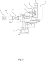
- a substitute electrical diagram of the system is shown in Figure 2 .
- the reference electrode 6 is provided with a reference electrode 6 shielding mechanism.
- This mechanism serves to cover the reference electrode 6 from the undesired effects of plasma, such as ion bombardment, deposition or electrode etching. Due to the negligibly small effective area of the reference electrode 6 compared to the main electrode 7 , the change in A AP area and surface roughness of the reference electrode 6 before and after plasma exposure is not very significant but may affect measurement accuracy in the long run. Service life, i.e., applicability, of the reference electrode 6 is extended by the reference electrode 6 shielding mechanism. After the measurement with the reference electrode 6 is completed, this mechanism is used to cover the reference electrode 6 with, for example, a mechanical screen, a cover.
- the mechanism performs shielding of the reference electrode 6 by moving the reference electrode 6 into the shielded area, e.g.,, it moves it behind the screen, inserts it into the inner area of the discharge chamber 1 , or turns it away from the plasma.
- the reference electrode 6 shielding mechanism can thus be in two positions. In the first position, the reference electrode 6 shielding mechanism allows the surface of the reference electrode 6 to be exposed to the plasma, and in the second position, the reference electrode shielding 6 mechanism covers the electrode from the plasma exposure.
- the object of the invention further relates to the method of plasma diagnostics shown in Figure 3 , in particular the determination of parameters describing the plasma, such as electron temperature, ion concentration, ion flux on wall sheath and voltage on the wall sheath.
- the present method of plasma diagnostics requires knowledge of the parasitic capacitive currents I cpar1 and I cpar2 passing through the electrode holders 6 , 7 to the ground and thus not flowing into the plasma.
- the values of the parasitic capacitive currents I cpar1 are measured by applying an alternating voltage from the generator 9 to the main electrode 7 and obtaining a volt-ampere characteristic.
- the values of the parasitic capacitive currents I cpar2 are measured by applying an alternating voltage from the generator 9 to the reference electrode 6 and obtaining a volt-ampere characteristic.
- the present method of plasma diagnostics is performed with the excited plasma in the discharge chamber 1 and comprises at least the following steps:
- this step is performed by calculation from the knowledge of waveform of U AP voltage on the reference electrode 6 and of current I AP flowing through the reference electrode 6 . From these values the dependence of current I PAP on voltage U AP is determined, where the monitored current flows only by real conductivity Y AP without capacitive current which flows through capacity C AP only. From this dependence, it is possible to determine the differential conductivity Y AP by calculating the trend tangent in the floating potential U fl region, when for a given voltage at the reference electrode the current of electrons and ions incident on it is balanced and the total current flowing is zero.
- the present method of plasma diagnostics comprises, in contrast to the prior art, the following steps: application of an alternating voltage of frequency f to the main electrode 7 located in the plasma discharge chamber 1. This step is performed, for example, by switching the switch 12. The supply of alternating voltage to the main electrode 7 thus takes place after the supply of alternating voltage to the reference electrode 6 is completed.
- the optimal harmonic component from the measured signals is the fundamental harmonic frequency corresponding to the frequency supplied by the harmonic generator 9.
- Figure 7 shows the dependence of the waveform of the high-frequency voltage U shHP (t) on the space charge sheath around the surface of the main electrode 7 with the thick dielectric 5 and the high-frequency current I HP (t) flowing through this electrode.
- the dependence of I pHP can be used to determine the saturated ion flux to the surface of the thick dielectric of the HP electrode and other plasma parameters such as T e and n i .
- the magnitude of the amplitude of the RF voltage U shHP determines, according to the relation (u1), the magnitude of the DC bias induced on the spatial charge sheath at the surface of the dielectric HP, which determines the energy of positive ions bombarding the dielectric surface.
Landscapes
- Physics & Mathematics (AREA)
- Engineering & Computer Science (AREA)
- Plasma & Fusion (AREA)
- Chemical & Material Sciences (AREA)
- Analytical Chemistry (AREA)
- Plasma Technology (AREA)
Description
- Plasma technologies of thin film deposition, high-frequency discharges, plasma surface treatment, plasma etching, plasma diagnostics.
- Low temperature plasma is widely used for PVD and PECVD thin film deposition, plasma etching, plasma activation and surface modification. For this purpose, an electrically conductive electrode is often inserted into the plasma, to which a high frequency (RF) voltage URFi is applied. It is known that major part of this voltage is concentrated on the positive space charge sheath occurring at the surface of this electrode due to the interaction with the plasma. Then, a direct (DC) voltage Ubi is generated on this charge sheath, the magnitude of which is given by a known relation (u1), where this relation is described and derived, for example, in the article: M.A. Liberman, A.J. Lichtenberg, Principles of Plasma Discharges and Materials Processing, Wiley, New York 1994 :

US 3,860,507 (1975 ). Furthermore, this method is used for plasma ion etching, where reactive ions are accelerated on the RF electrode by generated DC bias, which etch off the electrode material, as described, for example, in D.L. Flamm, Solid State Technol. 34, 47 (1991 ). Another great advantage of using a RF voltage to generate a DC bias accelerating positive ions is the ability to apply the RF voltage to the space charge wall sheath through a thick dielectric through its capacity. Thus, stable ion bombardment also of the surface of these dielectrics can be achieved without charging its surface during RF reactive sputtering of fully dielectric and thus electrically non-conductive targets, as described, for example, in thepatent U.S. Pat. No. 3,369,991 . - Dielectric substrates are used in a similar configuration also for RF reactive plasma ion etching in RF capacitive discharges, as described, for example, in the application US 2004/0014327 A1.
- An important part of this issue is the use of knowledge of waveforms of RF currents and voltages at this electrode to characterize plasma processes on the electrode surface. One is the knowledge of the DC accelerating voltage obtained from the RF voltage according to the relation (u1) or the DC bias is directly measured in the case of an electrically conductive electrode surface which interacts with the plasma. Another parameter that can be obtained from the knowledge of these waveforms of RF voltages and currents on the space charge sheath at the electrode surface is the ion flux. This methodology is described, for example, in: Mark A. Sobolewski, Measuring the ion current in high-density plasmas using radio-frequency current and voltage measurements, Journal of Applied Physics 90, 2660 (2001 ). Furthermore, it is possible to obtain from these RF signals parameters such as the electron temperature of plasma Te , the concentration of ions ni, as described in the article: Mark A. Sobolewski, Experimental test of models of high-plasma-density, radio-frequency sheaths, PHYSICAL REVIEW E, 59 (1999) 1059-1072 and further in the article: P. Sezemsky, V. Stranak, J. Kratochvil, M. Cada, R. Hippler, M. Hrabovsky, Z. Hubicka, Modified high frequency probe approach for diagnostics of highly reactive plasma, Plasma Sources Sci. Technol. 28 (2019) 115009 (10pp ). LUNDIN DANIEL ET AL: "Time-resolved ion flux and impedance measurements for process characterization in reactive high-power impulse magnetron sputtering", JOURNAL OF VACUUM SCIENCE, vol. 34, no. 4, 6 June 2016 discloses a new planar ion flux probe, based on the Sobolewski method, for time-resolved plasma characterization in inherently noisy pulsed plasma discharges.
CZ31194 U1 - The methods described in these articles have the advantage that they work reliably even when the conductive RF electrode is covered with a dielectric layer. However, the limiting condition is that this dielectric layer must be so thin that the RF voltage drop that occurs thereon by the passage of the RF current is negligible compared to the RF voltage drop on the space charge wall sheath in the plasma. However, if the dielectric layer is thick and capacity, dielectric constant or surface area thereof is not known, it is not possible to determine the RF voltage drop across the space charge sheath at the surface of this thick dielectric.
- The above-mentioned disadvantages of the prior art are at least partially solved by a method of plasma diagnostics, according to
claim 1, in which an alternating voltage of frequency f in the range of values of 0.01-100 MHz is applied to a reference electrode. The reference electrode has a measurable and well-defined area AAP, it is located in a discharge chamber and in contact with the plasma excited in the discharge chamber. A first set of waveforms of electric current and voltage on the reference electrode corresponding to the current and voltage values measured on the electrode over a certain time interval is created, e.g., to obtain the time and volt-ampere characteristics of the reference probe. After the creation of the first set of values, the supply of voltage to the reference electrode is terminated. Subsequently, a second set of values is created, which is created from the first set of values by subtracting the parasitic current and voltage values, thereby obtaining the time and volt-ampere characteristics of the reference electrode without the influence of parasitic values. From the second set of values, the value of the differential conductivity YAP and the differential capacity of the reference electrode in the region of the floating potential of the plasma is determined, or for values close to the value of the floating potential of the plasma witherror 20%, e.g., by calculation of the tangent of dependence, direct calculation or direct measurement. In the next step, an alternating voltage of the same frequency is applied to the main electrode. The main electrode is also located in the discharge chamber and is in contact with the plasma. It is preferably designed as a planar electrode, e.g., rectangular or square. It is heterogeneously covered by a dielectric of an unknown dielectric constant, so it is not possible to accurately determine its surface and roughness by conventional measurement method. The roughness varies in different places, the thickness of the dielectric and its composition is not homogeneous. By measurement of RF voltage and current on the main electrode, a third set of waveforms of electric current and voltage on the main electrode over a certain time interval is created, e.g., in order to obtain time and volt-ampere characteristics of the main electrode. After the creation of the third set of values, the supply of voltage to the main electrode is terminated. Subsequently, a fourth set of values is created, which is formed from the third set of values by subtracting the parasitic values of current and voltage waveforms, thus obtaining the time and volt-ampere characteristics of the main electrode without the influence of undesired values. - From the fourth set of values, the value of the complex impedance ZHP of the main electrode is calculated according to the relation:

- The conductivity YAP and the capacity CAP are proportional to the ratio of the surfaces of the reference and main probe, i.e., YHP = k * YAP and CHP = k * CAP, where k = AHP / AAP. However, to complete the calculation, it is necessary to know the surface of the main electrode. Using real and imaginary components of complex impedance


- Advantageously, thanks to the present diagnostic method, the capacity of the dielectric that covers the main electrode can be determined. Due to the fact that the composition of the dielectric is heterogenous similarly to its thickness and roughness, it is practically impossible to determine the capacity of this dielectric and its dielectric constant by direct measurement. With the above-mentioned procedure, it is possible to determine the capacitance of this dielectric as

- Preferably, the operating frequency of the AC voltage is selected in the narrower range of 0.1-10 MHz, these values have the least effect on the plasma and allow a more accurate determination of parasitic currents and voltages of the main and reference electrodes. Preferably, the frequency of the alternating voltage is lower than the plasma frequency of the ions.
- In a preferred embodiment, the parasitic current and voltage values of the reference and main electrodes are obtained by applying an alternating voltage of the above-used frequency to the reference electrode and measuring the time volt-ampere characteristic of the reference electrode in the absence of plasma.
- Preferably, also with the aid of described plasma diagnostic method, the voltage of the wall sheath is calculated by measuring the current passing through the capacitor Cd as


- Preferably, the presented method comprises an intermediate step, where after the end of the measurement, or. applying a voltage to the reference electrode, the reference electrode is covered by the reference electrode shielding mechanism. After the measurement is terminated, it is possible to remove or shield the reference electrode from other measurements and work only with the HP electrode also for other conditions and parameters in plasma and different frequencies of high-frequency voltage UHP on the HP probe, if the Cd capacity does not change with this frequency.
- The above-mentioned drawbacks of the prior art are further at least partially eliminated by a system for plasma diagnostics, according to
claim 8, comprising a discharge chamber, a pump adapted to create and maintain low pressure in a discharge chamber, where low pressure means a pressure below atmospheric. The system further includes a plasma source, a harmonic generator, and at least one measuring device that allows monitoring of voltage and current values on the selected electrical circuit component. The system further includes a main electrode with surface covered with a dielectric. The main electrode is placed in the discharge chamber in contact with the plasma when it is excited. The dielectric covers the electrode heterogeneously both in thickness and roughness and in composition. Therefore, it is not possible in principle to determine the size of the area of the main electrode, as well as the dielectric constant of the dielectric. The system further includes a reference electrode located no more than 5 cm from the main electrode in the discharge chamber in contact with the plasma when excited. The system further includes a switch for selectively connecting the main electrode or reference electrode to the harmonic generator. - The system further comprises a reference electrode shielding mechanism. This mechanism has two operating positions, where in the first position it exposes the surface of the reference electrode to the plasma and in the second position it hides this surface from the plasma.
- Preferably, the reference electrode shielding is designed as a mechanical cover or screen, which hides the reference probe from the influence of the plasma.
- Preferably, the reference electrode shielding is designed as a mechanism for moving the reference electrode. For shielding from the plasma, it can therefore move it to a shielded area, for example to an opening in the discharge chamber adapted for insertion of the reference electrode, possibly behind the screen. Alternatively, the reference electrode shielding mechanism may shield the electrode with its base, e.g., after rotation.
- Preferably, the operating frequency of the AC voltage provided by the harmonic generator is selected in the range of 0.1-10 MHz.
- The summary of the invention is further explained on the basis of examples of its realization, which are described with the help of accompanying drawings, where:
-
Figure 1 shows a schematic arrangement of a system for plasma diagnostics. -
Figure 2 is an substitute circuit diagram of a system for plasma diagnostics. -
Figure 3 is a diagram of the present method of plasma diagnostics. -
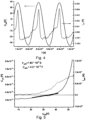
Figure 4 shows an example of the measured high-frequency voltage UAP and current IAP waveforms on the reference RF probe. -
Figure 5 shows an example of determination of the differential conductivity YAP and the dynamic capacity CAP of the space charge sheath formed at the surface of the reference electrode in the proximity of the floating potential. These parameters are determined from the knowledge of UAP (t) and IAP (t) waveforms. The graph shows the dependence of the current IpAP, which is the RF current flowing only by the real admittance YAP, on the voltage UAP and further the dependence of the dynamic capacity of the space charge sheath CAP on the voltage on the probe UAP. -
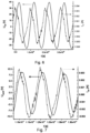
Figure 6 shows an example of the measured high frequency voltage UHP and current IHP waveforms on the electrode with a thick dielectric on the main electrode. -
Figure 7 shows an example of waveforms of the calculated high-frequency voltage UshHP on the space charge sheath around the surface of main electrode with the thick dielectric and of the high-frequency current IHP flowing through this electrode. -
Figure 8 shows the dependence of the determined current IpHP, which passes only through the real conductivity YHP, on the voltage UshHP present on the space charge sheath at the surface of the thick dielectric of the main electrode and the dependence of the dynamic capacity of the space charge sheath CHP on the voltage UHP. - The invention will be further clarified by means of exemplary embodiments with reference to the respective drawings, which, however, have do not limit scope of protection.
- The object of the invention is the system for plasma diagnostics shown in
Figure 1 and comprising adischarge chamber 1 and apump 2 adapted to create and maintain low pressure in thedischarge chamber 1, wherein working pressure in the discharge chamber is in the range of atmospheric pressure up to about 10-5 Pa. However, the range of working pressures does not limit scope of the protection of the invention and choice thereof depends on the specific application. Thepump 2 can be any or a combination of the following types of pumps: rotary pump, diaphragm pump, diffusion pump, sorption pump, getter, ionization pump or turbomolecular pump. Thedischarge chamber 1 further comprises aplasma source 3 adapted to generate plasma in the interior of thedischarge chamber 1. Theplasma source 3 is selected depending on the desired application for which the plasma is used. Theplasma source 3 is, for example, a pair of electrodes of opposite polarities, between which an electric field of sufficient intensity is excited to excite the plasma. Theplasma source 3 may further also comprise magnetic elements, such as a coil or a permanent magnet, in order to excite a magnetic field in the proximity of the plasma. Theplasma source 3 is controllable, wherein the controllable plasma parameters are, for example, the power of the source, the frequency of the source, etc. For selected applications and use of the described method of plasma diagnostics, it is optimal to choose low-temperature plasma. Another part of thedischarge chamber 1 is a working gas reservoir 4, which supplies the working gas or a mixture of working gases to thedischarge chamber 1 through a supply system of tubes and valves. The working gas or mixture thereof is selected depending on the application for which the plasma is used. The system for plasma diagnostics further comprises agenerator 9 providing an AC voltage with the frequency of the order of 0.01-100 MHz, wherein the AC voltage provided by thegenerator 9 may have a selectable waveform, e.g., sawtooth, triangular, rectangular, sinusoidal, pulsed, etc.,main electrode 7 andreference electrode 6. Themain electrode 7 is located in thedischarge chamber 1 near the plasma. Due to the repeated use in thedischarge chamber 1, themain electrode 7 is covered with adielectric 5 of unknown composition, roughness and size. The thickness of the dielectric 5 is in the range of 0.1-10 cm. In principle, it is not possible to calculate the area of the dielectric 5, or the area ofmain electrode 7, on the basis of knowledge of the geometric dimensions of themain electrode 7. A considerable amount of material is deposited on themain electrode 7, or on the dielectric 5, in thedischarge chamber 1 during repeated use, e.g., undesirable deposition during PECVD processes, sputtering from the target, etc. Likewise, the surface of themain electrode 7, or the dielectric 5, is bombarded by ions of the plasma, whereby this surface can be etched or sputtered. Both processes are strongly heterogenous, so sputtering, etching and deposition can take place at different speeds at different points on the surface. In addition, oxidation of the surface may occur upon completion of a particular process and exposure of the interior of thedischarge chamber 1 to the outside atmosphere. The resulting surface of themain electrode 7 and the dielectric 5 thus has different thicknesses, and in particular an unknown value of the dielectric constant and the capacity Cd , which makes it impossible to use it for plasma diagnostics. Thereference electrode 6 is located in thedischarge chamber 1 near themain electrode 7, or at a distance of 0.1-10 cm. Thereference electrode 6 is cylindrical in shape, e.g., in the form of a wire. This form of the reference probe is advantageous because it has easily definable dimensions of diameter and length, but at the same time it has a small effective area with respect to the plasma, and thus the above-mentioned problems of themain electrode 7, i.e. deposition or sputtering, are negligible. The system further contains amatching unit 10 connected to theharmonic generator 9 and adapted to change parameters which affect the main andreference electrodes unit 10 is connected to thegenerator 9 via a blockingcapacitor 13 with a capacity CV. - The system further comprises a
switch 12, which serves to selectively apply voltage from the matchingunit 10 to either themain electrode 7 or thereference electrode 6. Alternatively, twoharmonic generators 9 and two matchingunits 10 can be used, each for one of theelectrodes oscilloscope 8 or a multimeter 11 is used. Theoscilloscope 8 is preferably designed as a two-channel oscilloscope 8. The multimeter 11 serves to measure electrical quantities, especially voltage, current, resistance, capacity, impedance, inductance, etc. for both AC and DC voltage. Theoscilloscope 8 and the multimeter 11 serve to monitor the current and voltage waveforms and other electrical parameters on themain probe 7 and thereference probe 6. - The
main electrode 7 is provided with a radio frequency current transformer 14 of inductance LrHP and acapacitive voltage meter 15 with a terminating resistor RrvHP. From this resistor RrvHP, a signal corresponding to the waveform of electrical quantities over time at themain electrode 7 is fed to theoscilloscope 8 or other measuring device. The signal corresponding to the waveform of electrical quantities over time on the current transformer 14 LrHP is applied through a terminating resistor RrHP to theoscilloscope 8 or other measuring device. - The
reference electrode 6 is provided with a radio frequency current transformer 14 of inductance LrAP and acapacitive voltage meter 15 with a terminating resistor RrvAP. From this resistor RrvAP, a signal corresponding to the waveform of electrical quantities over time at thereference electrode 6 is fed to theoscilloscope 8 or other measuring device. The signal corresponding to the waveform of electrical quantities over time on the current transformer 14 LrAP is applied through a terminating resistor RrAP to theoscilloscope 8 or other measuring device. For direct measurement of the induced DC bias voltage on thereference electrode 6, the radio frequency voltage UAP is fed to the direct voltmeter 11 through a low-pass filter formed by the inductance Lt and the capacitance Ct. A substitute electrical diagram of the system is shown inFigure 2 . - In the exemplary embodiment, the
reference electrode 6 is provided with areference electrode 6 shielding mechanism. This mechanism serves to cover thereference electrode 6 from the undesired effects of plasma, such as ion bombardment, deposition or electrode etching. Due to the negligibly small effective area of thereference electrode 6 compared to themain electrode 7, the change in AAP area and surface roughness of thereference electrode 6 before and after plasma exposure is not very significant but may affect measurement accuracy in the long run. Service life, i.e., applicability, of thereference electrode 6 is extended by thereference electrode 6 shielding mechanism. After the measurement with thereference electrode 6 is completed, this mechanism is used to cover thereference electrode 6 with, for example, a mechanical screen, a cover. In other exemplary embodiments, the mechanism performs shielding of thereference electrode 6 by moving thereference electrode 6 into the shielded area, e.g.,, it moves it behind the screen, inserts it into the inner area of thedischarge chamber 1, or turns it away from the plasma. Thereference electrode 6 shielding mechanism can thus be in two positions. In the first position, thereference electrode 6 shielding mechanism allows the surface of thereference electrode 6 to be exposed to the plasma, and in the second position, the reference electrode shielding 6 mechanism covers the electrode from the plasma exposure. - The object of the invention further relates to the method of plasma diagnostics shown in
Figure 3 , in particular the determination of parameters describing the plasma, such as electron temperature, ion concentration, ion flux on wall sheath and voltage on the wall sheath. - The present method of plasma diagnostics requires knowledge of the parasitic capacitive currents Icpar1 and Icpar2 passing through the
electrode holders generator 9 to themain electrode 7 and obtaining a volt-ampere characteristic. The values of the parasitic capacitive currents Icpar2 are measured by applying an alternating voltage from thegenerator 9 to thereference electrode 6 and obtaining a volt-ampere characteristic. - The present method of plasma diagnostics is performed with the excited plasma in the
discharge chamber 1 and comprises at least the following steps: - application of an alternating voltage provided by the
harmonic generator 9 through theswitch 12 to thereference electrode 6, which is located in thedischarge chamber 1 with the excited plasma. - generation of a first set of values of the waveforms of the electric current and voltage on the
reference electrode 6. This step corresponds to the measurement of the volt-ampere characteristic. The data are read by a voltmeter 11, avoltage meter 15 or anoscilloscope 8. For example, these data are stored either in a memory unit of a given measuring device, a cloud or in a computer storage with which the measuring device can be communicatively connected. The data of the first set of values can also reflect the time dependence of the measured values. - - generation of a second set of values of the waveforms of the electric current and voltage on the
reference electrode 6 by subtracting the parasitic values of the current Icpar2 and the voltage of thereference electrode 6 from the first set of values. This gives data that correspond to the measured values of thereference electrode 6 in the plasma. The time dependence of the waveforms of the high-frequency voltage UAP and the IAP current on thereference electrode 6 after subtracting the parasitic capacitive current Icpar2 in the presence of the low-temperature plasma generated by theplasma source 3 is shown inFigure 4 . - determination of the differential conductivity YAP of the space charge sheath around the surface of the
reference electrode 6 and the differential capacity CAP of the reference electrode. These values are obtained from the second set of values for values close to the value of the floating potential of the plasma just excited in thedischarge chamber 1. - In practice, this step is performed by calculation from the knowledge of waveform of UAP voltage on the
reference electrode 6 and of current IAP flowing through thereference electrode 6. From these values the dependence of current IPAP on voltage UAP is determined, where the monitored current flows only by real conductivity YAP without capacitive current which flows through capacity CAP only. From this dependence, it is possible to determine the differential conductivity YAP by calculating the trend tangent in the floating potential Ufl region, when for a given voltage at the reference electrode the current of electrons and ions incident on it is balanced and the total current flowing is zero. - This dependence and the described calculation are shown in
Figure 5 . - The present method of plasma diagnostics comprises, in contrast to the prior art, the following steps:
application of an alternating voltage of frequency f to themain electrode 7 located in theplasma discharge chamber 1. This step is performed, for example, by switching theswitch 12. The supply of alternating voltage to themain electrode 7 thus takes place after the supply of alternating voltage to thereference electrode 6 is completed. - generation of a third set of values of waveforms of electric current and voltage on the
main electrode 7. This step corresponds to the measurement of the volt-ampere characteristic. The data are read by a voltmeter 11, avoltage meter 15 or anoscilloscope 8. For example, these data are stored either in a memory unit of a given measuring device, a cloud or in a computer storage with which the measuring device can be communicatively connected. The data of the first set of values can also reflect the time dependence of the measured values. - generation of a fourth set of values of the waveforms of the electric current and voltage on the
main electrode 7 by subtracting the parasitic values of the current Icpar1 and the voltage of themain electrode 7 from the third set of values. This gives data which correspond to the measured values of themain electrode 7 in the plasma. The time dependence of the waveforms of the high-frequency voltage UHP and current IHP on themain electrode 7 after subtracting the parasitic capacitive current Icpar1 in the presence of the low-temperature plasma generated by theplasma source 3 are shown inFigure 6 . - determination of the complex impedance of the ZHP of the
main electrode 7 from the fourth set of values. - The complex impedance is generally calculated according to the following relation:

- For the calculation, the optimal harmonic component from the measured signals is the fundamental harmonic frequency corresponding to the frequency supplied by the
harmonic generator 9. - The following equation applies to the complex impedance:

main electrode 7 and thereference electrode 6. - The complex impedance can be divided into real and imaginary components, where the following equations apply to the partial components:


- For the conductivities obtained for the main and
reference electrodes electrodes - calculating the area of the
main electrode 7 using the relation
- By further calculation it is possible to determine the capacity of the dielectric 5 as follows:

- From the measured time dependence of the current IHP flowing through the
main electrode 7 and thanks to the knowledge of the capacity of the dielectric 5, it is possible to determine the voltage on the dielectric 5 by the relation

-
Figure 7 then shows the dependence of the waveform of the high-frequency voltage UshHP (t) on the space charge sheath around the surface of themain electrode 7 with thethick dielectric 5 and the high-frequency current IHP(t) flowing through this electrode. - In
Figure 8 , there is the dependence of the determined current IpHP passing through only the real conductivity YHP on the voltage UshHP present on the space charge sheath at the surface of thethick dielectric 5 of themain electrode 7 and the dependence of the dynamic capacity of the space charge sheath CHP on the voltage UshHP. - From the knowledge of the measured waveform of IHP, the waveform of the RF voltage Ucd(t) was determined from relation (1) and then, according to relation (2), the waveform of the voltage on the space charge sheath at the HP electrode UshHP(t) was determined. In
Figure 7 , there is an example of the searched waveforms of the calculated high-frequency voltage. - This information can be used to describe the physical processes around the HP electrode. In
Figure 8 , there is the dependence of the determined current IpHP passing through only the real conductivity YHP on the voltage UshHP present on the space charge sheath at the surface of the thick dielectric of the electrode HP and the dependence of the dynamic capacity of the space charge sheath CHP on the voltage UshHP. - The dependence of IpHP (UshHP ) can be used to determine the saturated ion flux to the surface of the thick dielectric of the HP electrode and other plasma parameters such as T e and ni. The magnitude of the amplitude of the RF voltage UshHP determines, according to the relation (u1), the magnitude of the DC bias induced on the spatial charge sheath at the surface of the dielectric HP, which determines the energy of positive ions bombarding the dielectric surface.
- Diagnostics of reactive processes in plasma on the dielectric surface, plasma surface treatment and deposition of thin films using high-frequency voltages on dielectric substrates, plasma etching, diagnostics of low-temperature plasma.
-
- 1- discharge chamber
- 2 - pump
- 3 - plasma source
- 4 - working gas tank
- 5 - dielectric
- 6 - reference electrode
- 7 - main electrode
- 8 - oscilloscope
- 9 - harmonic RF generator
- 10 - matching unit
- 11 - voltmeter
- 12 - switch
- 13 - blocking capacitor
- 14 - current transformer LrHP
- 15 - voltmeter
Claims (11)
- A method of plasma diagnostics comprising the steps of:- application of an alternating voltage of frequency f to a reference electrode (6) of measurable area AAP located in a plasma discharge chamber (1);- generation of a first set of values of the electric current and voltage waveforms on the reference electrode (6);- termination of applying the alternating voltage to the reference electrode (6);- generation of a second set of values of the of the electric current and voltage waveforms on the reference electrode (6) by subtracting the parasitic values of the current and voltage of the reference electrode (6) from the first set of values;- and determination of the differential conductivity YAP of the space charge sheath around the surface of the reference electrode (6) and the differential capacity CAP of the reference electrode (6), wherein these quantities are calculated from the second set of values for the values close to the floating potential of the plasma excited in the discharge chamber (1),wherein the method further comprises the steps:- application of an alternating voltage of frequency f to a dielectric-covered main electrode (7) placed in the plasma discharge chamber (1), wherein the area of the main electrode (7) AHP is unknown;- wherein the value of the frequency f is the same value as the frequency f of the alternating voltage applied to the reference electrode (6) and is in the range 0.01-100 MHz.- generation of a third set of values of the electric current and voltage waveforms on the main electrode (7);- generation of a fourth set of values of the electric current and voltage waveforms on the main electrode (7) by subtracting the parasitic values of the current and voltage of the main electrode (7) from the third set of values;- determination of the complex impedance ZHP of the main electrode (7) from the fourth set of values- and calculation of the area of the main electrode (7) AHP using the relationwhere the coefficient k corresponds to the ratio of the areas of the main electrode (7) and the reference electrode (6) and ω is the angular frequency of the voltage.

- The method of plasma diagnostics according to claim 1, wherein the capacitance of the dielectric (5) Cd covering the main electrode (7) is further calculated using the relation

- The method of plasma diagnostics according to any one of claims 1 to 2, wherein the value of the frequency f is in the range 0.1-10 MHz.
- The method of plasma diagnostics according to any one of claims 1 to 3, wherein the frequency f is lower than the plasma frequency of the ions.
- The method of plasma diagnostics according to any one of claims 1 to 4, wherein the parasitic values of current and voltage of the reference electrode (6) are obtained by applying an alternating voltage of frequency f to the reference electrode (6) and parasitic values of current and voltage of the main electrode (7) are obtained by applying an alternating voltage of frequency f to the main electrode (7), wherein the measurements are carried out in the absence of plasma.
- The method of plasma diagnostics according to any one of claims 1 to 5, wherein the values of at least one of the following plasma parameters are further determined: electron temperature, ion concentration, ion flux to the dielectric surface and voltage on the wall sheath.
- The method of plasma diagnostics according to any one of claims 1 to 6, wherein after termination of the termination step of applying the alternating voltage to the reference electrode (6), the reference electrode (6) is covered by a reference electrode (6) shielding mechanism.
- A system for plasma diagnostics comprising a discharge chamber (1), a pump (2) designed to maintain a low pressure in the discharge chamber (1), a plasma source (3), a harmonic generator (9) and at least one measuring device (8, 11) adapted to monitor values of voltage and current on a selected electrical circuit component, wherein the system further comprises a dielectric (5) covered main electrode (7) of unknown area and surface roughness located in the discharge chamber (1), a reference electrode (6) located at most 5 cm from the main electrode (7) in the discharge chamber (1), a switch (12) for selectively connecting the main electrode (7) or the reference electrode (6) to the harmonic generator (9) and a reference electrode (6) shielding mechanism, wherein the mechanism has two operating positions, and wherein the mechanism is configured such that, in the case that it is in the first operating position, it allows the surface of the reference electrode (6) to be exposed to the plasma, and in the case that it is in the second operating position, it hides the surface of the reference electrode (6) from the plasma.
- The system for plasma diagnostics according to claim 8, wherein the reference electrode (6) shielding mechanism is designed as a mechanical cover or screen.
- The system for plasma diagnostics according to claim 8, wherein the reference electrode (6) shielding mechanism is designed as a mechanism for moving the reference electrode (6).
- The system for plasma diagnostics according to any one of claims 8 to 10, wherein the harmonic generator (9) provides an alternating voltage with frequency values in the range 0.1-10 MHz.
Applications Claiming Priority (1)
| Application Number | Priority Date | Filing Date | Title |
|---|---|---|---|
| PCT/CZ2021/050113 WO2023061519A1 (en) | 2021-10-15 | 2021-10-15 | Method and system for plasma diagnostics |
Publications (2)
| Publication Number | Publication Date |
|---|---|
| EP4416753A1 EP4416753A1 (en) | 2024-08-21 |
| EP4416753B1 true EP4416753B1 (en) | 2025-02-19 |
Family
ID=78821727
Family Applications (1)
| Application Number | Title | Priority Date | Filing Date |
|---|---|---|---|
| EP21819717.6A Active EP4416753B1 (en) | 2021-10-15 | 2021-10-15 | Method and system for plasma diagnostics |
Country Status (2)
| Country | Link |
|---|---|
| EP (1) | EP4416753B1 (en) |
| WO (1) | WO2023061519A1 (en) |
Family Cites Families (2)
| Publication number | Priority date | Publication date | Assignee | Title |
|---|---|---|---|---|
| CZ31194U1 (en) * | 2017-10-04 | 2017-11-14 | Univerzita Palackého v Olomouci | Impedance spectrograph for measuring impedance of deposited layer in discharge plasma |
| SE544676C2 (en) * | 2020-04-06 | 2022-10-11 | Ionautics Ab | Method for monitoring process conditions of, and method for controlling, a plasma pvd process |
-
2021
- 2021-10-15 WO PCT/CZ2021/050113 patent/WO2023061519A1/en not_active Ceased
- 2021-10-15 EP EP21819717.6A patent/EP4416753B1/en active Active
Also Published As
| Publication number | Publication date |
|---|---|
| EP4416753A1 (en) | 2024-08-21 |
| WO2023061519A1 (en) | 2023-04-20 |
Similar Documents
| Publication | Publication Date | Title |
|---|---|---|
| Braithwaite et al. | An electrostatic probe technique for RF plasma | |
| JP3937453B2 (en) | Method and apparatus for measuring ion flow in plasma | |
| JP5209313B2 (en) | Probe for measuring characteristics of plasma excitation current, and associated plasma reactor | |
| US6771481B2 (en) | Plasma processing apparatus for processing semiconductor wafer using plasma | |
| Gahan et al. | Comparison of plasma parameters determined with a Langmuir probe and with a retarding field energy analyzer | |
| Sobolewski | Measuring the ion current in electrical discharges using radio-frequency current and voltage measurements | |
| Mausbach | Parametrization of the Laframboise theory for cylindrical Langmuir probe analysis | |
| Sobolewski | In situ measurement of electron emission yield at silicon dioxide surfaces exposed to argon plasmas | |
| Guo et al. | Time-resolved current and voltage measurements on a pulsed rf inductively coupled plasma | |
| Marakhtanov et al. | Stable and unstable behavior of inductively coupled electronegative discharges | |
| Eser et al. | Plasma characterization in sputtering processes using the Langmuir probe technique | |
| Ebihara et al. | Application of the dielectric barrier discharge to detect defects in a teflon coated metal surface | |
| Bang et al. | A plasma diagnostic technique using a floating probe for the dielectric deposition process | |
| US5359282A (en) | Plasma diagnosing apparatus | |
| Smith et al. | Observation of the ion-ion transition in an SF6 discharge using a fast floating double probe | |
| Cruden et al. | Detection of chamber conditioning by CF 4 plasmas in an inductively coupled plasma reactor | |
| WO2023061519A1 (en) | Method and system for plasma diagnostics | |
| Savas et al. | Capacitive probes for rf process plasmas | |
| Welzel et al. | A time-resolved Langmuir double-probe method for the investigation of pulsed magnetron discharges | |
| Wilken et al. | Development of a radio-frequency glow discharge source with integrated voltage and current probes | |
| Mahony et al. | Electrical characterization of radio frequency discharges | |
| Čada et al. | Probe diagnostics of the RF barrier-torch discharge at atmospheric pressure | |
| Sobolewski | In situ measurement of electron emission yield at Si and SiO2 surfaces exposed to Ar/CF4 plasmas | |
| Graham et al. | Electrical and optical characterisation of capacitively and inductively coupled GEC reference cells | |
| KR20230092941A (en) | Non-invasive measurement of plasma systems |
Legal Events
| Date | Code | Title | Description |
|---|---|---|---|
| STAA | Information on the status of an ep patent application or granted ep patent |
Free format text: STATUS: UNKNOWN |
|
| STAA | Information on the status of an ep patent application or granted ep patent |
Free format text: STATUS: THE INTERNATIONAL PUBLICATION HAS BEEN MADE |
|
| PUAI | Public reference made under article 153(3) epc to a published international application that has entered the european phase |
Free format text: ORIGINAL CODE: 0009012 |
|
| STAA | Information on the status of an ep patent application or granted ep patent |
Free format text: STATUS: REQUEST FOR EXAMINATION WAS MADE |
|
| 17P | Request for examination filed |
Effective date: 20240509 |
|
| AK | Designated contracting states |
Kind code of ref document: A1 Designated state(s): AL AT BE BG CH CY CZ DE DK EE ES FI FR GB GR HR HU IE IS IT LI LT LU LV MC MK MT NL NO PL PT RO RS SE SI SK SM TR |
|
| GRAP | Despatch of communication of intention to grant a patent |
Free format text: ORIGINAL CODE: EPIDOSNIGR1 |
|
| STAA | Information on the status of an ep patent application or granted ep patent |
Free format text: STATUS: GRANT OF PATENT IS INTENDED |
|
| DAV | Request for validation of the european patent (deleted) | ||
| DAX | Request for extension of the european patent (deleted) | ||
| INTG | Intention to grant announced |
Effective date: 20240927 |
|
| RIN1 | Information on inventor provided before grant (corrected) |
Inventor name: STRANAK, VITEZSLAV Inventor name: DVORAKOVA, MICHAELA Inventor name: KSIROVA, PETRA Inventor name: OLEJNICEK, JIRI Inventor name: CADA, MARTIN Inventor name: CTVRTLIK, RADIM Inventor name: SCHOVANEK, PETR Inventor name: HRUBANTOVA, ANETA Inventor name: HUBICKA, ZDENEK Inventor name: HRABOVSKY, MIROSLAV |
|
| GRAS | Grant fee paid |
Free format text: ORIGINAL CODE: EPIDOSNIGR3 |
|
| GRAA | (expected) grant |
Free format text: ORIGINAL CODE: 0009210 |
|
| STAA | Information on the status of an ep patent application or granted ep patent |
Free format text: STATUS: THE PATENT HAS BEEN GRANTED |
|
| REG | Reference to a national code |
Ref country code: DE Ref legal event code: R081 Ref document number: 602021026483 Country of ref document: DE Owner name: UNIVERZITA PALACKEHO V OLOMOUCI, CZ Free format text: FORMER OWNERS: FYZIKALNI USTAV AV CR, V.V.I., PRAHA, CZ; UNIVERZITA PALACKEHO V OLOMOUCI, OLOMOUC, CZ Ref country code: DE Ref legal event code: R081 Ref document number: 602021026483 Country of ref document: DE Owner name: FYZIKALNI USTAV AV CR, V.V.I., CZ Free format text: FORMER OWNERS: FYZIKALNI USTAV AV CR, V.V.I., PRAHA, CZ; UNIVERZITA PALACKEHO V OLOMOUCI, OLOMOUC, CZ |
|
| AK | Designated contracting states |
Kind code of ref document: B1 Designated state(s): AL AT BE BG CH CY CZ DE DK EE ES FI FR GB GR HR HU IE IS IT LI LT LU LV MC MK MT NL NO PL PT RO RS SE SI SK SM TR |
|
| REG | Reference to a national code |
Ref country code: GB Ref legal event code: FG4D |
|
| REG | Reference to a national code |
Ref country code: CH Ref legal event code: EP |
|
| REG | Reference to a national code |
Ref country code: IE Ref legal event code: FG4D |
|
| REG | Reference to a national code |
Ref country code: DE Ref legal event code: R096 Ref document number: 602021026483 Country of ref document: DE |
|
| REG | Reference to a national code |
Ref country code: NL Ref legal event code: MP Effective date: 20250219 |
|
| PG25 | Lapsed in a contracting state [announced via postgrant information from national office to epo] |
Ref country code: RS Free format text: LAPSE BECAUSE OF FAILURE TO SUBMIT A TRANSLATION OF THE DESCRIPTION OR TO PAY THE FEE WITHIN THE PRESCRIBED TIME-LIMIT Effective date: 20250519 |
|
| PG25 | Lapsed in a contracting state [announced via postgrant information from national office to epo] |
Ref country code: FI Free format text: LAPSE BECAUSE OF FAILURE TO SUBMIT A TRANSLATION OF THE DESCRIPTION OR TO PAY THE FEE WITHIN THE PRESCRIBED TIME-LIMIT Effective date: 20250219 |
|
| PG25 | Lapsed in a contracting state [announced via postgrant information from national office to epo] |
Ref country code: PL Free format text: LAPSE BECAUSE OF FAILURE TO SUBMIT A TRANSLATION OF THE DESCRIPTION OR TO PAY THE FEE WITHIN THE PRESCRIBED TIME-LIMIT Effective date: 20250219 |
|
| PG25 | Lapsed in a contracting state [announced via postgrant information from national office to epo] |
Ref country code: ES Free format text: LAPSE BECAUSE OF FAILURE TO SUBMIT A TRANSLATION OF THE DESCRIPTION OR TO PAY THE FEE WITHIN THE PRESCRIBED TIME-LIMIT Effective date: 20250219 |
|
| REG | Reference to a national code |
Ref country code: LT Ref legal event code: MG9D |
|
| PG25 | Lapsed in a contracting state [announced via postgrant information from national office to epo] |
Ref country code: IS Free format text: LAPSE BECAUSE OF FAILURE TO SUBMIT A TRANSLATION OF THE DESCRIPTION OR TO PAY THE FEE WITHIN THE PRESCRIBED TIME-LIMIT Effective date: 20250619 Ref country code: NO Free format text: LAPSE BECAUSE OF FAILURE TO SUBMIT A TRANSLATION OF THE DESCRIPTION OR TO PAY THE FEE WITHIN THE PRESCRIBED TIME-LIMIT Effective date: 20250519 |
|
| PG25 | Lapsed in a contracting state [announced via postgrant information from national office to epo] |
Ref country code: NL Free format text: LAPSE BECAUSE OF FAILURE TO SUBMIT A TRANSLATION OF THE DESCRIPTION OR TO PAY THE FEE WITHIN THE PRESCRIBED TIME-LIMIT Effective date: 20250219 |
|
| PG25 | Lapsed in a contracting state [announced via postgrant information from national office to epo] |
Ref country code: HR Free format text: LAPSE BECAUSE OF FAILURE TO SUBMIT A TRANSLATION OF THE DESCRIPTION OR TO PAY THE FEE WITHIN THE PRESCRIBED TIME-LIMIT Effective date: 20250219 |
|
| PG25 | Lapsed in a contracting state [announced via postgrant information from national office to epo] |
Ref country code: LV Free format text: LAPSE BECAUSE OF FAILURE TO SUBMIT A TRANSLATION OF THE DESCRIPTION OR TO PAY THE FEE WITHIN THE PRESCRIBED TIME-LIMIT Effective date: 20250219 Ref country code: PT Free format text: LAPSE BECAUSE OF FAILURE TO SUBMIT A TRANSLATION OF THE DESCRIPTION OR TO PAY THE FEE WITHIN THE PRESCRIBED TIME-LIMIT Effective date: 20250620 |
|
| PG25 | Lapsed in a contracting state [announced via postgrant information from national office to epo] |
Ref country code: GR Free format text: LAPSE BECAUSE OF FAILURE TO SUBMIT A TRANSLATION OF THE DESCRIPTION OR TO PAY THE FEE WITHIN THE PRESCRIBED TIME-LIMIT Effective date: 20250520 Ref country code: BG Free format text: LAPSE BECAUSE OF FAILURE TO SUBMIT A TRANSLATION OF THE DESCRIPTION OR TO PAY THE FEE WITHIN THE PRESCRIBED TIME-LIMIT Effective date: 20250219 |
|
| PG25 | Lapsed in a contracting state [announced via postgrant information from national office to epo] |
Ref country code: SE Free format text: LAPSE BECAUSE OF FAILURE TO SUBMIT A TRANSLATION OF THE DESCRIPTION OR TO PAY THE FEE WITHIN THE PRESCRIBED TIME-LIMIT Effective date: 20250219 |
|
| PG25 | Lapsed in a contracting state [announced via postgrant information from national office to epo] |
Ref country code: SM Free format text: LAPSE BECAUSE OF FAILURE TO SUBMIT A TRANSLATION OF THE DESCRIPTION OR TO PAY THE FEE WITHIN THE PRESCRIBED TIME-LIMIT Effective date: 20250219 |
|
| PG25 | Lapsed in a contracting state [announced via postgrant information from national office to epo] |
Ref country code: DK Free format text: LAPSE BECAUSE OF FAILURE TO SUBMIT A TRANSLATION OF THE DESCRIPTION OR TO PAY THE FEE WITHIN THE PRESCRIBED TIME-LIMIT Effective date: 20250219 |
|
| PG25 | Lapsed in a contracting state [announced via postgrant information from national office to epo] |
Ref country code: IT Free format text: LAPSE BECAUSE OF FAILURE TO SUBMIT A TRANSLATION OF THE DESCRIPTION OR TO PAY THE FEE WITHIN THE PRESCRIBED TIME-LIMIT Effective date: 20250219 |
|
| PG25 | Lapsed in a contracting state [announced via postgrant information from national office to epo] |
Ref country code: AT Free format text: LAPSE BECAUSE OF FAILURE TO SUBMIT A TRANSLATION OF THE DESCRIPTION OR TO PAY THE FEE WITHIN THE PRESCRIBED TIME-LIMIT Effective date: 20250219 |
|
| PGFP | Annual fee paid to national office [announced via postgrant information from national office to epo] |
Ref country code: FR Payment date: 20250925 Year of fee payment: 5 |
|
| PG25 | Lapsed in a contracting state [announced via postgrant information from national office to epo] |
Ref country code: EE Free format text: LAPSE BECAUSE OF FAILURE TO SUBMIT A TRANSLATION OF THE DESCRIPTION OR TO PAY THE FEE WITHIN THE PRESCRIBED TIME-LIMIT Effective date: 20250219 Ref country code: CZ Free format text: LAPSE BECAUSE OF FAILURE TO SUBMIT A TRANSLATION OF THE DESCRIPTION OR TO PAY THE FEE WITHIN THE PRESCRIBED TIME-LIMIT Effective date: 20250219 |
|
| PG25 | Lapsed in a contracting state [announced via postgrant information from national office to epo] |
Ref country code: RO Free format text: LAPSE BECAUSE OF FAILURE TO SUBMIT A TRANSLATION OF THE DESCRIPTION OR TO PAY THE FEE WITHIN THE PRESCRIBED TIME-LIMIT Effective date: 20250219 |
|
| PG25 | Lapsed in a contracting state [announced via postgrant information from national office to epo] |
Ref country code: SK Free format text: LAPSE BECAUSE OF FAILURE TO SUBMIT A TRANSLATION OF THE DESCRIPTION OR TO PAY THE FEE WITHIN THE PRESCRIBED TIME-LIMIT Effective date: 20250219 |
|
| REG | Reference to a national code |
Ref country code: DE Ref legal event code: R097 Ref document number: 602021026483 Country of ref document: DE |
|
| PLBE | No opposition filed within time limit |
Free format text: ORIGINAL CODE: 0009261 |
|
| STAA | Information on the status of an ep patent application or granted ep patent |
Free format text: STATUS: NO OPPOSITION FILED WITHIN TIME LIMIT |
|
| PGFP | Annual fee paid to national office [announced via postgrant information from national office to epo] |
Ref country code: DE Payment date: 20250925 Year of fee payment: 5 |
|
| 26N | No opposition filed |
Effective date: 20251120 |