EP4415479A1 - Resistance temperature detector (rtd) sensor-based fault status reporting for a positive temperature coefficient (ptc) heater - Google Patents
Resistance temperature detector (rtd) sensor-based fault status reporting for a positive temperature coefficient (ptc) heater Download PDFInfo
- Publication number
- EP4415479A1 EP4415479A1 EP24152163.2A EP24152163A EP4415479A1 EP 4415479 A1 EP4415479 A1 EP 4415479A1 EP 24152163 A EP24152163 A EP 24152163A EP 4415479 A1 EP4415479 A1 EP 4415479A1
- Authority
- EP
- European Patent Office
- Prior art keywords
- ptc heater
- rtd
- temperature
- ptc
- logic unit
- Prior art date
- Legal status (The legal status is an assumption and is not a legal conclusion. Google has not performed a legal analysis and makes no representation as to the accuracy of the status listed.)
- Pending
Links
Images



Classifications
-
- H—ELECTRICITY
- H05—ELECTRIC TECHNIQUES NOT OTHERWISE PROVIDED FOR
- H05B—ELECTRIC HEATING; ELECTRIC LIGHT SOURCES NOT OTHERWISE PROVIDED FOR; CIRCUIT ARRANGEMENTS FOR ELECTRIC LIGHT SOURCES, IN GENERAL
- H05B3/00—Ohmic-resistance heating
- H05B3/20—Heating elements having extended surface area substantially in a two-dimensional [2D] plane, e.g. plate-heater
- H05B3/22—Heating elements having extended surface area substantially in a two-dimensional [2D] plane, e.g. plate-heater non-flexible
- H05B3/28—Heating elements having extended surface area substantially in a two-dimensional [2D] plane, e.g. plate-heater non-flexible heating conductor embedded in insulating material
- H05B3/286—Heating elements having extended surface area substantially in a two-dimensional [2D] plane, e.g. plate-heater non-flexible heating conductor embedded in insulating material the insulating material being an organic material, e.g. plastic
-
- G—PHYSICS
- G01—MEASURING; TESTING
- G01K—MEASURING TEMPERATURE; MEASURING QUANTITY OF HEAT; THERMALLY-SENSITIVE ELEMENTS NOT OTHERWISE PROVIDED FOR
- G01K7/00—Measuring temperature based on the use of electric or magnetic elements directly sensitive to heat ; Power supply therefor, e.g. using thermoelectric elements
- G01K7/16—Measuring temperature based on the use of electric or magnetic elements directly sensitive to heat ; Power supply therefor, e.g. using thermoelectric elements using resistive elements
- G01K7/18—Measuring temperature based on the use of electric or magnetic elements directly sensitive to heat ; Power supply therefor, e.g. using thermoelectric elements using resistive elements the element being a linear resistance, e.g. platinum resistance thermometer
- G01K7/183—Measuring temperature based on the use of electric or magnetic elements directly sensitive to heat ; Power supply therefor, e.g. using thermoelectric elements using resistive elements the element being a linear resistance, e.g. platinum resistance thermometer characterised by the use of the resistive element
-
- G—PHYSICS
- G01—MEASURING; TESTING
- G01K—MEASURING TEMPERATURE; MEASURING QUANTITY OF HEAT; THERMALLY-SENSITIVE ELEMENTS NOT OTHERWISE PROVIDED FOR
- G01K7/00—Measuring temperature based on the use of electric or magnetic elements directly sensitive to heat ; Power supply therefor, e.g. using thermoelectric elements
- G01K7/16—Measuring temperature based on the use of electric or magnetic elements directly sensitive to heat ; Power supply therefor, e.g. using thermoelectric elements using resistive elements
- G01K7/22—Measuring temperature based on the use of electric or magnetic elements directly sensitive to heat ; Power supply therefor, e.g. using thermoelectric elements using resistive elements the element being a non-linear resistance, e.g. thermistor
-
- G—PHYSICS
- G01—MEASURING; TESTING
- G01K—MEASURING TEMPERATURE; MEASURING QUANTITY OF HEAT; THERMALLY-SENSITIVE ELEMENTS NOT OTHERWISE PROVIDED FOR
- G01K7/00—Measuring temperature based on the use of electric or magnetic elements directly sensitive to heat ; Power supply therefor, e.g. using thermoelectric elements
- G01K7/16—Measuring temperature based on the use of electric or magnetic elements directly sensitive to heat ; Power supply therefor, e.g. using thermoelectric elements using resistive elements
- G01K2007/163—Measuring temperature based on the use of electric or magnetic elements directly sensitive to heat ; Power supply therefor, e.g. using thermoelectric elements using resistive elements provided with specially adapted connectors
-
- H—ELECTRICITY
- H05—ELECTRIC TECHNIQUES NOT OTHERWISE PROVIDED FOR
- H05B—ELECTRIC HEATING; ELECTRIC LIGHT SOURCES NOT OTHERWISE PROVIDED FOR; CIRCUIT ARRANGEMENTS FOR ELECTRIC LIGHT SOURCES, IN GENERAL
- H05B2203/00—Aspects relating to Ohmic resistive heating covered by group H05B3/00
- H05B2203/002—Heaters using a particular layout for the resistive material or resistive elements
- H05B2203/006—Heaters using a particular layout for the resistive material or resistive elements using interdigitated electrodes
-
- H—ELECTRICITY
- H05—ELECTRIC TECHNIQUES NOT OTHERWISE PROVIDED FOR
- H05B—ELECTRIC HEATING; ELECTRIC LIGHT SOURCES NOT OTHERWISE PROVIDED FOR; CIRCUIT ARRANGEMENTS FOR ELECTRIC LIGHT SOURCES, IN GENERAL
- H05B2203/00—Aspects relating to Ohmic resistive heating covered by group H05B3/00
- H05B2203/002—Heaters using a particular layout for the resistive material or resistive elements
- H05B2203/007—Heaters using a particular layout for the resistive material or resistive elements using multiple electrically connected resistive elements or resistive zones
-
- H—ELECTRICITY
- H05—ELECTRIC TECHNIQUES NOT OTHERWISE PROVIDED FOR
- H05B—ELECTRIC HEATING; ELECTRIC LIGHT SOURCES NOT OTHERWISE PROVIDED FOR; CIRCUIT ARRANGEMENTS FOR ELECTRIC LIGHT SOURCES, IN GENERAL
- H05B2203/00—Aspects relating to Ohmic resistive heating covered by group H05B3/00
- H05B2203/02—Heaters using heating elements having a positive temperature coefficient
Definitions
- the present disclosure relates to fault reporting for a positive temperature coefficient heater (PTC) and, in particular, to resistance temperature detector (RTD) sensor-based fault reporting apparatus and method for a PTC heater.
- PTC positive temperature coefficient heater
- RTD resistance temperature detector
- a PTC element-based heater has an inherent property of self-regulated heating operation, overheat protection and overload protection.
- fault status detection and reporting are still needed and provided by an external device.
- the fault reporting feature in particular is a mandated requirement for component and/or system health status.
- a positive temperature coefficient (PTC) heater apparatus includes a PTC heater, a resistance temperature detector (RTD) sensor mounted to the PTC heater and a controller logic unit electrically connected to the RTD sensor to receive readings of the RTD sensor, which, when the PTC heater is powered on, indicate whether the PTC heater is faulty.
- RTD resistance temperature detector
- the PTC heater includes dielectric layers, a first conducting trace comprising a first conducting trace portion interposed between the dielectric layers, a second conducting trace comprising a second conducting trace portion interposed between the dielectric layers and PTC heating patches, each being electrically connected between the first and second conducting trace portions and interposed between the dielectric layers.
- the RTD sensor is mounted to an exterior face of one of the dielectric layers.
- an insulating layer is disposed about the RTD sensor at the exterior face of the one of the dielectric layers.
- the PTC heater is maintained at an initial temperature and powered on at that initial temperature, a temperature of the PTC heater increases once the PTC heater is powered on and a signal from the RTD sensor triggers a timer in the controller logic unit to begin timing an RTD sensing duration of a predefined length of time once the temperature of the PTC heater increases beyond a predefined threshold temperature range.
- the controller logic unit establishes a predefined range of temperatures and the controller logic unit indicates that the PTC heater is faulty in an event the readings of the RTD sensor indicate that a temperature of the PTC heater is outside the predefined range of temperatures and the timer indicates that the predefined length of time passed.
- the controller logic unit includes a resistive network filter, which is receptive of a voltage supply and the readings of the RTD sensor, and which outputs a differential signal corresponding to a change in temperature of the PTC heater, a difference amplifier, which is receptive of a voltage supply, and which amplifies the differential signal of the resistive network filter and a multiplexer with an astable timer, which is receptive of multiple signals from the difference amplifier, and which is configured to select one of the multiple signals for analysis by the controller logic unit.
- a resistive network filter which is receptive of a voltage supply and the readings of the RTD sensor, and which outputs a differential signal corresponding to a change in temperature of the PTC heater
- a difference amplifier which is receptive of a voltage supply, and which amplifies the differential signal of the resistive network filter
- a multiplexer with an astable timer which is receptive of multiple signals from the difference amplifier, and which is configured to select one of the multiple signals for analysis
- a positive temperature coefficient (PTC) heater apparatus includes a PTC heater, multiple resistance temperature detector (RTD) sensors, each of which is mounted to the PTC heater, and a controller logic unit electrically connected to each of the multiple RTD sensors to receive readings of each of the multiple RTD sensors, which, when the PTC heater is powered on, respectively indicate whether the PTC heater is faulty.
- PTC positive temperature coefficient
- the PTC heater includes dielectric layers, a first conducting trace comprising a first conducting trace portion interposed between the dielectric layers, a second conducting trace comprising a second conducting trace portion interposed between the dielectric layers and PTC heating patches, each being electrically connected between the first and second conducting trace portions and interposed between the dielectric layers.
- each of the multiple RTD sensors is mounted to an exterior face of one of the dielectric layers.
- an insulating layer is disposed about each of the multiple RTD sensors at the exterior face of the one of the dielectric layers.
- the PTC heater is maintained at an initial temperature and powered on at that initial temperature, a temperature of the PTC heater increases once the PTC heater is powered on and a signal from any one of the multiple RTD sensors triggers a timer in the controller logic unit to begin timing an RTD sensing duration of a predefined length of time once the temperature of the PTC heater increases beyond a predefined threshold temperature range.
- the controller logic unit establishes a predefined range of temperatures and the controller logic unit indicates that the PTC heater is faulty in an event the readings of any one of the multiple RTD sensors indicate that a temperature of the PTC heater is outside the predefined range of temperatures and the timer indicates that the predefined length of time passed.
- the controller logic unit includes multiple resistive network filters, each of which is receptive of a voltage supply and the readings of a corresponding one of the multiple RTD sensors, and each of which outputs a differential signal corresponding to a change in temperature of the PTC heater, multiple difference amplifiers, each of which is receptive of a voltage supply, and each of which amplifies the differential signal of a corresponding one of the multiple resistive network filters and multiple multiplexers with astable timers, each of which is receptive of multiple signals from a corresponding one of the multiple difference amplifiers, and each of which is configured to select one of the multiple signals for analysis by the controller logic unit.
- a method of operating a positive temperature coefficient (PTC) heater apparatus in which a resistance temperature detector (RTD) sensor is mounted to a PTC heater includes maintaining the PTC heater at an initial temperature and powering the PTC heater on at the initial temperature, initiating a timer once readings of the RTD sensor indicate that a temperature of the PTC heater increases beyond a predefined threshold temperature range and indicating that the PTC heater is faulty in an event the readings of the RTD sensor indicate that the temperature of the PTC heater is outside a predefined range of temperatures and the timer indicates that a predefined length of time passed.
- RTD resistance temperature detector
- the method further includes insulating the RTD sensor from ambient temperatures.
- the method further includes setting the initial temperature at about -55°C, setting the predefined threshold temperature range at about -35°C to about -30°C and setting the predefined range of temperatures at about 10°C to about 80°C.
- the indicating includes indicating that the PTC heater has at least one of an open circuit and insufficient power in an event the readings of the RTD sensor indicate that the temperature of the PTC heater is below the predefined range of temperatures and the timer indicates that the predefined length of time passed.
- the indicating includes indicating that the PTC heater has at least one of a short circuit, negative temperature coefficient (NTC) behavior and damage in an event the readings of the RTD sensor indicate that the temperature of the PTC heater is above the predefined range of temperatures and the timer indicates that the predefined length of time passed.
- NTC negative temperature coefficient
- multiple RTD sensors are mounted to the PTC heater
- the initiating includes initiating a timer once readings of any one of the multiple RTD sensors indicate that a temperature of the PTC heater increases beyond a predefined threshold temperature range and the indicating includes indicating that the PTC heater is faulty in an event the readings of any one of the multiple RTD sensors indicate that the temperature of the PTC heater is outside a predefined range of temperatures and the timer indicates that a predefined length of time passed.
- a PTC heater apparatus in which an RTD temperature sensor is mounted on a PTC heater (multiple RTD temperature sensors can be provided for large PTC heaters). Controller logic will be packed in a separate enclosure (i.e., in a potted or metal case) that is connected to RTD sensor. A fault reporting device will be connected in line with the PTC heater. The PTC heater will be maintained at -55°C ambient and powered on, at which point, the heater temperature will increase. The RTD temperature sensor resistance begins changing based on the temperature increase (or decrease).
- a sensing signal from the RTD sensor will trigger a timer in the controller logic to indicate a good status for a set heating duration.
- the heating duration is set to avoid false heater fault reports during the ramp up of the heater from the -55°C ambient and can be based on test data of multiple heaters with different power densities.
- the controller logic will report the good status when the temperature of the heater is between a given range of temperatures (e.g., 10°C to 80°C) after the heater is powered on and will report a fault status when the temperature of the heater is below the range, which is indicative of there being an open circuit incident or insufficient power due to PTC element damage. In other exemplary cases, the controller logic will report a fault status when the heater temperature is above the range, which is indicative of a short circuit, negative temperature coefficient (NTC) behavior or PTC property degradation.
- NTC negative temperature coefficient
- the proposed fault reporting apparatus and method covers detections of failure modes such as heater open, insufficient power due to heating patch damage, heater short and heater resistance increase due to PTC property degradation.
- a PTC heater apparatus 101 includes a PTC heater 110, an RTD sensor 120 that is mounted to the PTC heater 110 and a controller logic unit 140.
- the controller logic unit 140 is electrically connected to at least the RTD sensor 120 and is configured to receive readings of the RTD sensor 120. The readings of the RTD sensor 120 can indicate whether the PTC heater 110 is faulty when the PTC heater 110 is powered on.
- a connector 145 can be connected to the controller logic unit 140 so that the controller logic unit 140 can be communicative with an external device (i.e., an external computing device and display).
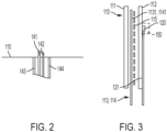
- the controller logic unit 140 is electrically connected to the RTD sensor 120 by way of first and second conductive lines 141 and 142, which provide electrical output from the RTD sensor 120 to the controller logic unit 140.
- the controller logic unit 140 can be connected to the PTC heater 110 by a first "line” conductor 143 and by a second "return” conductor 144 which are the supply connections to the PTC heater 110.
- the PTC heater 110 includes first and second dielectric layers 111 and 112, which can include or be provided as thermoplastic, a first conducting trace 113, a second conducting trace 114 and PTC heating patches 115.
- the first conducting trace 113 includes a first conducting trace portion 1131, which is interposed between the first and second dielectric layers 111 and 112
- the second conducting trace 114 includes a second conducting trace portion 1141, which is interposed between the first and second dielectric layers 111 and 112.
- the PTC heating patches 115 are each electrically connected between the first and second conducting trace portions 1131 and 1141 and are each interposed between the first and second dielectric layers 111 and 112.
- Each of the PTC heating patches 115 can be formed of an electrical resistance heater material whose resistance increases significantly with temperature.
- the RTD sensor 120 can be mounted to an exterior face 121 of one of the first and second dielectric layers 111 and 112.
- the PTC heater apparatus 101 can additionally include an insulating layer 150.
- the insulating layer 150 is disposed about the RTD sensor 120 at the exterior face 121.
- the first and second conducting trace portions 1131 and 1141 can be patterned along peripheral sides of the first and second dielectric layers 111 and 112 and can include first and second crossing traces 1132 and 1142 that extend across the first and second dielectric layers 111 and 112 in an interleaved formation.
- Each of the PTC heating patches 115 can be arranged in a lattice formation 1151 to electrically connect between proximal portions of the first and second crossing traces 1132 and 1142.
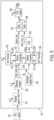
- the controller logic unit 140 includes a first window comparator 501, a first threshold setting unit 502, which is receptive of a voltage supply and which sets a predefined range of temperatures for the first window comparator 501, a second window comparator 503 and a second threshold setting unit 504, which sets a predefined threshold temperature range for the second window comparator 503.
- the controller logic unit 140 further includes a timer 505 downstream from the second window comparator 503, a fault creation unit 506, which is receptive of a voltage supply, and first and second diodes 507 and 508.
- the first diode 507 is electrically interposed between the first window comparator 501 and the fault creation unit 506 and the second diode 508 is electrically interposed between the timer 505 and the fault creation unit 506.
- the controller logic unit 140 includes a resistive network filter 510, a difference amplifier 520 and a multiplexer with an astable timer 530.
- the resistive network filter 510 is receptive of a voltage supply and the readings of the RTD sensor 120.
- the resistive network filter 510 also outputs a differential signal that corresponds to a change in temperature of the PTC heater 110 (see FIG. 1 ).
- the difference amplifier 520 is receptive of a voltage supply and amplifies the differential signal of the resistive network filter 510. Outputs of the difference amplifier 520 are provided to the first and second window comparators 501 and 503.
- the multiplexer with the astable timer 530 is receptive of multiple signals from the difference amplifier 520 and is configured to select one of the multiple signals for analysis by the controller logic unit.
- An output of the multiplexer with the astable timer 530 is output to the first and second window comparators 501 and 503.
- the PTC heater 110 is maintained at an initial temperature of about -55°C and is powered on at that initial temperature.
- the temperature of the PTC heater 110 increases once the PTC heater 110 is powered on.
- a signal from the RTD sensor 120 triggers the timer 505 to begin timing an RTD sensing duration of a predefined length of time, such as five minutes or five seconds, for example, once the temperature of the PTC heater 110 increases beyond the predefined threshold temperature range of about -35°C to about -30°C as set by the second threshold setting unit 504.
- the controller logic unit 140 is configured to establish the predefined range of temperatures, such as about 10°C to about 80°C as set by the first threshold setting unit 502.
- the controller logic unit 140 is further configured to indicate that the PTC heater 110 is faulty (i.e., in a faulty condition) in an event the readings of the RTD sensor 120 indicate that a temperature of the PTC heater 110 is outside the predefined range of temperatures and the timer indicates that the predefined length of time passed.
- the controller logic unit 140 can indicate that the PTC heater 110 has at least one of an open circuit and insufficient power in an event the readings of the RTD sensor 120 indicate that the temperature of the PTC heater 110 is below the predefined range of temperatures (i.e., below about 10°C) and the timer 505 indicates that the predefined length of time passed.
- the controller logic unit 140 can indicate that the PTC heater 110 has at least one of a short circuit, negative temperature coefficient (NTC) behavior and damage in an event the readings of the RTD sensor 120 indicate that the temperature of the PTC heater 110 is above the predefined range of temperatures (i.e., above about 80°C) and the timer 505 indicates that the predefined length of time passed.
- NTC negative temperature coefficient
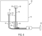
- a PTC heater apparatus 601 is provided and includes similar features as the PTC heater apparatus 101 of FIG. 1 except that multiple resistance temperature detector (RTD) sensors 120 are mounted to the PTC heater 110 and the controller logic unit 140 is electrically connected to each of the multiple RTD sensors 120 to receive readings of each of the multiple RTD sensors 120, which, when the PTC heater 110 is powered on, respectively indicate whether the PTC heater 110 is faulty.
- the controller logic unit 140 can include, but is not required to include, multiple resistive network filters 510, multiple difference amplifiers 520 and multiple multiplexer with the astable timers 530 (see FIG. 5 ).
- the multiple resistive network filters 510, the multiple difference amplifiers 520 and the multiple multiplexers with the astable timers 530 operate similarly as described above for each of the multiple RTD sensors 120.
- RTD sensors 120 there can be RTD sensors 120 of multiple number like 1, 2, 4, 8, etc. depending on heater size and requirements to increase the sensing area. For example, if there are two RTD sensors 120 in a large PTC heater 110, there can be two resistive network filters 510, two difference amplifiers 520 and one multiplexer (4: 1) with one astable timer 530.
- a method 700 of operating a PTC heater apparatus in which an RTD sensor is mounted to a PTC heater as described above (or in which multiple RTD sensors are mounted to a PTC heater), is provided.
- the method 700 includes insulating the RTD sensor from ambient temperatures (block 701), maintaining the PTC heater at an initial temperature at about -55°C and powering the PTC heater on at the initial temperature (block 702), initiating a timer once readings of the RTD sensor indicate that a temperature of the PTC heater increases beyond a predefined threshold temperature range at about -35°C to about - 30°C (block 703) and indicating that the PTC heater is faulty in an event the readings of the RTD sensor indicate that the temperature of the PTC heater is outside a predefined range of temperatures, which are set at about 10°C to about 80°C, and the timer indicates that a predefined length of time passed (block 704).
- the indicating of block 704 can include indicating that the PTC heater has at least one of an open circuit and insufficient power in an event the readings of the RTD sensor indicate that the temperature of the PTC heater is below the predefined range of temperatures and the timer indicates that the predefined length of time passed (block 7041) or indicating that the PTC heater has at least one of a short circuit, negative temperature coefficient (NTC) behavior and damage in an event the readings of the RTD sensor indicate that the temperature of the PTC heater is above the predefined range of temperatures and the timer indicates that the predefined length of time passed (block 7042).
- NTC negative temperature coefficient
- the RTD temperature sensor can be generic to any type of PTC heater, such that no configuration or re-configuration of the PTC heater or the RTD temperature sensor is required.
- the mounting of the RTD temperature sensor can be relatively easily adopted for multiple sensing inputs for a large PTC heater.
Landscapes
- Physics & Mathematics (AREA)
- General Physics & Mathematics (AREA)
- Nonlinear Science (AREA)
- Control Of Resistance Heating (AREA)
Abstract
Description
- This application claims the benefit of
Indian Patent Application No. 202311006749 filed February 2, 2023 - The present disclosure relates to fault reporting for a positive temperature coefficient heater (PTC) and, in particular, to resistance temperature detector (RTD) sensor-based fault reporting apparatus and method for a PTC heater.
- In aerospace technologies, there is often a requirement to adopt, in a water and waste system of an aircraft for example, a simplified freeze protection heater that can be self-regulated and that has a lightweight and thin construction. A PTC element-based heater has an inherent property of self-regulated heating operation, overheat protection and overload protection. However, with PTC heaters, fault status detection and reporting are still needed and provided by an external device. The fault reporting feature in particular is a mandated requirement for component and/or system health status.
- Currently, existing external controllers for use with PTC heaters tend to be large and costly. Their control logic is often incompatible with PTC element-based heaters. Thus, there is a need for a PTC heater that does not require an external controller or device for fault detection and reporting.
- According to an aspect of the disclosure, a positive temperature coefficient (PTC) heater apparatus is provided. The PTC heater apparatus includes a PTC heater, a resistance temperature detector (RTD) sensor mounted to the PTC heater and a controller logic unit electrically connected to the RTD sensor to receive readings of the RTD sensor, which, when the PTC heater is powered on, indicate whether the PTC heater is faulty.
- In accordance with additional or alternative embodiments, the PTC heater includes dielectric layers, a first conducting trace comprising a first conducting trace portion interposed between the dielectric layers, a second conducting trace comprising a second conducting trace portion interposed between the dielectric layers and PTC heating patches, each being electrically connected between the first and second conducting trace portions and interposed between the dielectric layers.
- In accordance with additional or alternative embodiments, the RTD sensor is mounted to an exterior face of one of the dielectric layers.
- In accordance with additional or alternative embodiments, an insulating layer is disposed about the RTD sensor at the exterior face of the one of the dielectric layers.
- In accordance with additional or alternative embodiments, the PTC heater is maintained at an initial temperature and powered on at that initial temperature, a temperature of the PTC heater increases once the PTC heater is powered on and a signal from the RTD sensor triggers a timer in the controller logic unit to begin timing an RTD sensing duration of a predefined length of time once the temperature of the PTC heater increases beyond a predefined threshold temperature range.
- In accordance with additional or alternative embodiments, the controller logic unit establishes a predefined range of temperatures and the controller logic unit indicates that the PTC heater is faulty in an event the readings of the RTD sensor indicate that a temperature of the PTC heater is outside the predefined range of temperatures and the timer indicates that the predefined length of time passed.
- In accordance with additional or alternative embodiments, the controller logic unit includes a resistive network filter, which is receptive of a voltage supply and the readings of the RTD sensor, and which outputs a differential signal corresponding to a change in temperature of the PTC heater, a difference amplifier, which is receptive of a voltage supply, and which amplifies the differential signal of the resistive network filter and a multiplexer with an astable timer, which is receptive of multiple signals from the difference amplifier, and which is configured to select one of the multiple signals for analysis by the controller logic unit.
- According to an aspect of the disclosure, a positive temperature coefficient (PTC) heater apparatus is provided and includes a PTC heater, multiple resistance temperature detector (RTD) sensors, each of which is mounted to the PTC heater, and a controller logic unit electrically connected to each of the multiple RTD sensors to receive readings of each of the multiple RTD sensors, which, when the PTC heater is powered on, respectively indicate whether the PTC heater is faulty.
- In accordance with additional or alternative embodiments, the PTC heater includes dielectric layers, a first conducting trace comprising a first conducting trace portion interposed between the dielectric layers, a second conducting trace comprising a second conducting trace portion interposed between the dielectric layers and PTC heating patches, each being electrically connected between the first and second conducting trace portions and interposed between the dielectric layers.
- In accordance with additional or alternative embodiments, each of the multiple RTD sensors is mounted to an exterior face of one of the dielectric layers.
- In accordance with additional or alternative embodiments, an insulating layer is disposed about each of the multiple RTD sensors at the exterior face of the one of the dielectric layers.
- In accordance with additional or alternative embodiments, the PTC heater is maintained at an initial temperature and powered on at that initial temperature, a temperature of the PTC heater increases once the PTC heater is powered on and a signal from any one of the multiple RTD sensors triggers a timer in the controller logic unit to begin timing an RTD sensing duration of a predefined length of time once the temperature of the PTC heater increases beyond a predefined threshold temperature range.
- In accordance with additional or alternative embodiments, the controller logic unit establishes a predefined range of temperatures and the controller logic unit indicates that the PTC heater is faulty in an event the readings of any one of the multiple RTD sensors indicate that a temperature of the PTC heater is outside the predefined range of temperatures and the timer indicates that the predefined length of time passed.
- In accordance with additional or alternative embodiments, the controller logic unit includes multiple resistive network filters, each of which is receptive of a voltage supply and the readings of a corresponding one of the multiple RTD sensors, and each of which outputs a differential signal corresponding to a change in temperature of the PTC heater, multiple difference amplifiers, each of which is receptive of a voltage supply, and each of which amplifies the differential signal of a corresponding one of the multiple resistive network filters and multiple multiplexers with astable timers, each of which is receptive of multiple signals from a corresponding one of the multiple difference amplifiers, and each of which is configured to select one of the multiple signals for analysis by the controller logic unit.
- According to an aspect of the disclosure, a method of operating a positive temperature coefficient (PTC) heater apparatus in which a resistance temperature detector (RTD) sensor is mounted to a PTC heater is provided and includes maintaining the PTC heater at an initial temperature and powering the PTC heater on at the initial temperature, initiating a timer once readings of the RTD sensor indicate that a temperature of the PTC heater increases beyond a predefined threshold temperature range and indicating that the PTC heater is faulty in an event the readings of the RTD sensor indicate that the temperature of the PTC heater is outside a predefined range of temperatures and the timer indicates that a predefined length of time passed.
- In accordance with additional or alternative embodiments, the method further includes insulating the RTD sensor from ambient temperatures.
- In accordance with additional or alternative embodiments, the method further includes setting the initial temperature at about -55°C, setting the predefined threshold temperature range at about -35°C to about -30°C and setting the predefined range of temperatures at about 10°C to about 80°C.
- In accordance with additional or alternative embodiments, the indicating includes indicating that the PTC heater has at least one of an open circuit and insufficient power in an event the readings of the RTD sensor indicate that the temperature of the PTC heater is below the predefined range of temperatures and the timer indicates that the predefined length of time passed.
- In accordance with additional or alternative embodiments, the indicating includes indicating that the PTC heater has at least one of a short circuit, negative temperature coefficient (NTC) behavior and damage in an event the readings of the RTD sensor indicate that the temperature of the PTC heater is above the predefined range of temperatures and the timer indicates that the predefined length of time passed.
- In accordance with additional or alternative embodiments, multiple RTD sensors are mounted to the PTC heater, the initiating includes initiating a timer once readings of any one of the multiple RTD sensors indicate that a temperature of the PTC heater increases beyond a predefined threshold temperature range and the indicating includes indicating that the PTC heater is faulty in an event the readings of any one of the multiple RTD sensors indicate that the temperature of the PTC heater is outside a predefined range of temperatures and the timer indicates that a predefined length of time passed.
- Additional features and advantages are realized through the techniques of the present disclosure. Other embodiments and aspects of the disclosure are described in detail herein and are considered a part of the claimed technical concept. For a better understanding of the disclosure with the advantages and the features, refer to the description and to the drawings.
- For a more complete understanding of this disclosure, reference is now made to the following brief description, taken in connection with the accompanying drawings and detailed description, wherein like reference numerals represent like parts:
-
FIG. 1 is a top-down view of a PTC heater with one RTD sensor apparatus in accordance with embodiments; -
FIG. 2 is an enlarged view of the portion ofFIG. 1 surrounded bydashed box 150 in accordance with embodiments; -
FIG. 3 is a side view of the PTC heater apparatus ofFIG. 1 in accordance with embodiments; -
FIG. 4 is a top-down view of components of a PTC heater of the PTC heater apparatus ofFIG. 1 in accordance with embodiments; -
FIG. 5 is a schematic diagram of a controller logic unit of the PTC heater apparatus ofFIG. 1 ; -
FIG. 6 is a top-down view of a PTC heater apparatus with multiple RTD sensors in accordance with embodiments; and -
FIG. 7 is a flow diagram illustrating a method of operating a positive temperature coefficient (PTC) heater apparatus in accordance with embodiments. - As will be described below, a PTC heater apparatus is provided in which an RTD temperature sensor is mounted on a PTC heater (multiple RTD temperature sensors can be provided for large PTC heaters). Controller logic will be packed in a separate enclosure (i.e., in a potted or metal case) that is connected to RTD sensor. A fault reporting device will be connected in line with the PTC heater. The PTC heater will be maintained at -55°C ambient and powered on, at which point, the heater temperature will increase. The RTD temperature sensor resistance begins changing based on the temperature increase (or decrease). When the heater temperature crosses between a given temperature (e.g., -35°C to -30°C), a sensing signal from the RTD sensor will trigger a timer in the controller logic to indicate a good status for a set heating duration. The heating duration is set to avoid false heater fault reports during the ramp up of the heater from the -55°C ambient and can be based on test data of multiple heaters with different power densities.
- In some exemplary cases, the controller logic will report the good status when the temperature of the heater is between a given range of temperatures (e.g., 10°C to 80°C) after the heater is powered on and will report a fault status when the temperature of the heater is below the range, which is indicative of there being an open circuit incident or insufficient power due to PTC element damage. In other exemplary cases, the controller logic will report a fault status when the heater temperature is above the range, which is indicative of a short circuit, negative temperature coefficient (NTC) behavior or PTC property degradation.
- Thus, the proposed fault reporting apparatus and method covers detections of failure modes such as heater open, insufficient power due to heating patch damage, heater short and heater resistance increase due to PTC property degradation.
- With reference to
FIG. 1 , aPTC heater apparatus 101 is provided and includes aPTC heater 110, anRTD sensor 120 that is mounted to thePTC heater 110 and acontroller logic unit 140. Thecontroller logic unit 140 is electrically connected to at least theRTD sensor 120 and is configured to receive readings of theRTD sensor 120. The readings of theRTD sensor 120 can indicate whether thePTC heater 110 is faulty when thePTC heater 110 is powered on. Aconnector 145 can be connected to thecontroller logic unit 140 so that thecontroller logic unit 140 can be communicative with an external device (i.e., an external computing device and display). - With continued reference to
FIG. 1 and with additional reference toFIG. 2 , thecontroller logic unit 140 is electrically connected to theRTD sensor 120 by way of first and secondconductive lines RTD sensor 120 to thecontroller logic unit 140. In addition, thecontroller logic unit 140 can be connected to thePTC heater 110 by a first "line"conductor 143 and by a second "return"conductor 144 which are the supply connections to thePTC heater 110. - With continued reference to
FIG. 1 and with additional reference toFIGS. 3 and4 , thePTC heater 110 includes first and seconddielectric layers trace 113, a second conductingtrace 114 andPTC heating patches 115. The first conductingtrace 113 includes a first conducting trace portion 1131, which is interposed between the first and seconddielectric layers trace 114 includes a second conductingtrace portion 1141, which is interposed between the first and seconddielectric layers PTC heating patches 115 are each electrically connected between the first and second conductingtrace portions 1131 and 1141 and are each interposed between the first and seconddielectric layers PTC heating patches 115 can be formed of an electrical resistance heater material whose resistance increases significantly with temperature. - As shown in
FIG. 3 , theRTD sensor 120 can be mounted to anexterior face 121 of one of the first and seconddielectric layers PTC heater apparatus 101 can additionally include an insulatinglayer 150. The insulatinglayer 150 is disposed about theRTD sensor 120 at theexterior face 121. - As shown in
FIG. 4 , the first and second conductingtrace portions 1131 and 1141 can be patterned along peripheral sides of the first and seconddielectric layers dielectric layers PTC heating patches 115 can be arranged in alattice formation 1151 to electrically connect between proximal portions of the first and second crossing traces 1132 and 1142. With this configuration, voltage applied to thePTC heater 110 results in a generally uniform heating pattern in the absence of a fault in thePTC heater 110. - With reference to
FIG. 5 , thecontroller logic unit 140 includes afirst window comparator 501, a firstthreshold setting unit 502, which is receptive of a voltage supply and which sets a predefined range of temperatures for thefirst window comparator 501, asecond window comparator 503 and a secondthreshold setting unit 504, which sets a predefined threshold temperature range for thesecond window comparator 503. Thecontroller logic unit 140 further includes atimer 505 downstream from thesecond window comparator 503, afault creation unit 506, which is receptive of a voltage supply, and first andsecond diodes first diode 507 is electrically interposed between thefirst window comparator 501 and thefault creation unit 506 and thesecond diode 508 is electrically interposed between thetimer 505 and thefault creation unit 506. - In addition, as shown in
FIG. 5 , thecontroller logic unit 140 includes aresistive network filter 510, adifference amplifier 520 and a multiplexer with anastable timer 530. Theresistive network filter 510 is receptive of a voltage supply and the readings of theRTD sensor 120. Theresistive network filter 510 also outputs a differential signal that corresponds to a change in temperature of the PTC heater 110 (seeFIG. 1 ). Thedifference amplifier 520 is receptive of a voltage supply and amplifies the differential signal of theresistive network filter 510. Outputs of thedifference amplifier 520 are provided to the first andsecond window comparators astable timer 530 is receptive of multiple signals from thedifference amplifier 520 and is configured to select one of the multiple signals for analysis by the controller logic unit. An output of the multiplexer with theastable timer 530 is output to the first andsecond window comparators - The following will describe an operation of the
PTC heater apparatus 101 described above refers to various temperatures. These temperatures are exemplary and not intended to otherwise limit the scope of the application in any way. - In an operation of the
PTC heater apparatus 101, with thecontroller logic unit 140 provided as described above, thePTC heater 110 is maintained at an initial temperature of about -55°C and is powered on at that initial temperature. The temperature of thePTC heater 110 increases once thePTC heater 110 is powered on. A signal from theRTD sensor 120 triggers thetimer 505 to begin timing an RTD sensing duration of a predefined length of time, such as five minutes or five seconds, for example, once the temperature of thePTC heater 110 increases beyond the predefined threshold temperature range of about -35°C to about -30°C as set by the secondthreshold setting unit 504. Thecontroller logic unit 140 is configured to establish the predefined range of temperatures, such as about 10°C to about 80°C as set by the firstthreshold setting unit 502. - The
controller logic unit 140 is further configured to indicate that thePTC heater 110 is faulty (i.e., in a faulty condition) in an event the readings of theRTD sensor 120 indicate that a temperature of thePTC heater 110 is outside the predefined range of temperatures and the timer indicates that the predefined length of time passed. In greater detail, thecontroller logic unit 140 can indicate that thePTC heater 110 has at least one of an open circuit and insufficient power in an event the readings of theRTD sensor 120 indicate that the temperature of thePTC heater 110 is below the predefined range of temperatures (i.e., below about 10°C) and thetimer 505 indicates that the predefined length of time passed. Conversely, thecontroller logic unit 140 can indicate that thePTC heater 110 has at least one of a short circuit, negative temperature coefficient (NTC) behavior and damage in an event the readings of theRTD sensor 120 indicate that the temperature of thePTC heater 110 is above the predefined range of temperatures (i.e., above about 80°C) and thetimer 505 indicates that the predefined length of time passed. - With reference to
FIG. 6 , aPTC heater apparatus 601 is provided and includes similar features as thePTC heater apparatus 101 ofFIG. 1 except that multiple resistance temperature detector (RTD)sensors 120 are mounted to thePTC heater 110 and thecontroller logic unit 140 is electrically connected to each of themultiple RTD sensors 120 to receive readings of each of themultiple RTD sensors 120, which, when thePTC heater 110 is powered on, respectively indicate whether thePTC heater 110 is faulty. Though not specifically shown inFIGS. 5 and6 , in thePTC heater apparatus 601 ofFIG. 6 , thecontroller logic unit 140 can include, but is not required to include, multiple resistive network filters 510,multiple difference amplifiers 520 and multiple multiplexer with the astable timers 530 (seeFIG. 5 ). The multiple resistive network filters 510, themultiple difference amplifiers 520 and the multiple multiplexers with theastable timers 530 operate similarly as described above for each of themultiple RTD sensors 120. - In accordance with embodiments, there can be
RTD sensors 120 of multiple number like 1, 2, 4, 8, etc. depending on heater size and requirements to increase the sensing area. For example, if there are twoRTD sensors 120 in alarge PTC heater 110, there can be two resistive network filters 510, twodifference amplifiers 520 and one multiplexer (4: 1) with oneastable timer 530. - With reference to
FIG. 7 , amethod 700 of operating a PTC heater apparatus, in which an RTD sensor is mounted to a PTC heater as described above (or in which multiple RTD sensors are mounted to a PTC heater), is provided. As shown inFIG. 7 , themethod 700 includes insulating the RTD sensor from ambient temperatures (block 701), maintaining the PTC heater at an initial temperature at about -55°C and powering the PTC heater on at the initial temperature (block 702), initiating a timer once readings of the RTD sensor indicate that a temperature of the PTC heater increases beyond a predefined threshold temperature range at about -35°C to about - 30°C (block 703) and indicating that the PTC heater is faulty in an event the readings of the RTD sensor indicate that the temperature of the PTC heater is outside a predefined range of temperatures, which are set at about 10°C to about 80°C, and the timer indicates that a predefined length of time passed (block 704). In accordance with embodiments, the indicating ofblock 704 can include indicating that the PTC heater has at least one of an open circuit and insufficient power in an event the readings of the RTD sensor indicate that the temperature of the PTC heater is below the predefined range of temperatures and the timer indicates that the predefined length of time passed (block 7041) or indicating that the PTC heater has at least one of a short circuit, negative temperature coefficient (NTC) behavior and damage in an event the readings of the RTD sensor indicate that the temperature of the PTC heater is above the predefined range of temperatures and the timer indicates that the predefined length of time passed (block 7042). - Technical effects and benefits of the present disclosure are the provision of an RTD temperature sensor mounted on a PTC heater to provide fault detection and reporting that meets requirements in a simple, cost effective and non-programmed manner. The RTD temperature sensor can be generic to any type of PTC heater, such that no configuration or re-configuration of the PTC heater or the RTD temperature sensor is required. The mounting of the RTD temperature sensor can be relatively easily adopted for multiple sensing inputs for a large PTC heater.
- The corresponding structures, materials, acts, and equivalents of all means or step-plus function elements in the claims below are intended to include any structure, material, or act for performing the function in combination with other claimed elements as specifically claimed. The description of the present disclosure has been presented for purposes of illustration and description, but is not intended to be exhaustive or limited to the technical concepts in the form disclosed. Many modifications and variations will be apparent to those of ordinary skill in the art without departing from the scope and spirit of the disclosure. The embodiments were chosen and described in order to best explain the principles of the disclosure and the practical application, and to enable others of ordinary skill in the art to understand the disclosure for various embodiments with various modifications as are suited to the particular use contemplated.
- While the preferred embodiments to the disclosure have been described, it will be understood that those skilled in the art, both now and in the future, may make various improvements and enhancements which fall within the scope of the claims which follow. These claims should be construed to maintain the proper protection for the disclosure first described.
Claims (15)
- A positive temperature coefficient (PTC) heater apparatus, comprising:a PTC heater;a resistance temperature detector (RTD) sensor mounted to the PTC heater; anda controller logic unit electrically connected to the RTD sensor to receive readings of the RTD sensor, which, when the PTC heater is powered on, indicate whether the PTC heater is faulty.
- The PTC heater apparatus according to claim 1, wherein the PTC heater comprises:dielectric layers;a first conducting trace comprising a first conducting trace portion interposed between the dielectric layers;a second conducting trace comprising a second conducting trace portion interposed between the dielectric layers; andPTC heating patches, each being electrically connected between the first and second conducting trace portions and interposed between the dielectric layers.
- The PTC heater apparatus according to claim 2, wherein the RTD sensor is mounted to an exterior face of one of the dielectric layers.
- The PTC heater apparatus according to claim 3, further comprising an insulating layer disposed about the RTD sensor at the exterior face of the one of the dielectric layers.
- The PTC heater apparatus according to any preceding claim, wherein:the PTC heater is maintained at an initial temperature and powered on at that initial temperature,a temperature of the PTC heater increases once the PTC heater is powered on, anda signal from the RTD sensor triggers a timer in the controller logic unit to begin timing an RTD sensing duration of a predefined length of time once the temperature of the PTC heater increases beyond a predefined threshold temperature range.
- The PTC heater apparatus according to claim 5, wherein:the controller logic unit establishes a predefined range of temperatures, andthe controller logic unit indicates that the PTC heater is faulty in an event the readings of the RTD sensor indicate that a temperature of the PTC heater is outside the predefined range of temperatures and the timer indicates that the predefined length of time passed.
- The PTC heater apparatus according to any preceding claim, wherein the controller logic unit comprises:a resistive network filter, which is receptive of a voltage supply and the readings of the RTD sensor, and which outputs a differential signal corresponding to a change in temperature of the PTC heater;a difference amplifier, which is receptive of a voltage supply, and which amplifies the differential signal of the resistive network filter; anda multiplexer with an astable timer, which is receptive of multiple signals from the difference amplifier, and which is configured to select one of the multiple signals for analysis by the controller logic unit.
- The positive temperature coefficient (PTC) heater apparatus, according to any preceding claim, further comprising:multiple resistance temperature detector (RTD) sensors, each of which is mounted to the PTC heater; anda controller logic unit electrically connected to each of the multiple RTD sensors to receive readings of each of the multiple RTD sensors, which, when the PTC heater is powered on, respectively indicate whether the PTC heater is faulty.
- The PTC heater apparatus according to claim 8, when dependent on claim 2, wherein each of the multiple RTD sensors is mounted to an exterior face of one of the dielectric layers,
optionally, further comprising an insulating layer disposed about each of the multiple RTD sensors at the exterior face of the one of the dielectric layers. - The PTC heater apparatus according to claim 8 or 9, wherein:the PTC heater is maintained at an initial temperature and powered on at that initial temperature,a temperature of the PTC heater increases once the PTC heater is powered on, anda signal from any one of the multiple RTD sensors triggers a timer in the controller logic unit to begin timing an RTD sensing duration of a predefined length of time once the temperature of the PTC heater increases beyond a predefined threshold temperature range,optionally, wherein:the controller logic unit establishes a predefined range of temperatures, andthe controller logic unit indicates that the PTC heater is faulty in an event the readings of any one of the multiple RTD sensors indicate that a temperature of the PTC heater is outside the predefined range of temperatures and the timer indicates that the predefined length of time passed.
- The PTC heater apparatus according to claim 8, 9 or 10 wherein the controller logic unit comprises:multiple resistive network filters, each of which is receptive of a voltage supply and the readings of a corresponding one of the multiple RTD sensors, and each of which outputs a differential signal corresponding to a change in temperature of the PTC heater;multiple difference amplifiers, each of which is receptive of a voltage supply, and each of which amplifies the differential signal of a corresponding one of the multiple resistive network filters; andmultiple multiplexers with astable timers, each of which is receptive of multiple signals from a corresponding one of the multiple difference amplifiers, and each of which is configured to select one of the multiple signals for analysis by the controller logic unit.
- A method of operating a positive temperature coefficient (PTC) heater apparatus in which a resistance temperature detector (RTD) sensor is mounted to a PTC heater, the method comprising:maintaining the PTC heater at an initial temperature and powering the PTC heater on at the initial temperature;initiating a timer once readings of the RTD sensor indicate that a temperature of the PTC heater increases beyond a predefined threshold temperature range; andindicating that the PTC heater is faulty in an event the readings of the RTD sensor indicate that the temperature of the PTC heater is outside a predefined range of temperatures and the timer indicates that a predefined length of time passed.
- The method according to claim 12, further comprising insulating the RTD sensor from ambient temperatures.
- The method according to claim 12 or 13, further comprising:setting the initial temperature at about -55°C;setting the predefined threshold temperature range at about -35°C to about - 30°C; andsetting the predefined range of temperatures at about 10°C to about 80°C.
- The method according to claim 12, 13 or 14, wherein the indicating comprises indicating that the PTC heater has at least one of an open circuit and insufficient power in an event the readings of the RTD sensor indicate that the temperature of the PTC heater is below the predefined range of temperatures and the timer indicates that the predefined length of time passed; and/orwherein the indicating comprises indicating that the PTC heater has at least one of a short circuit, negative temperature coefficient (NTC) behavior and damage in an event the readings of the RTD sensor indicate that the temperature of the PTC heater is above the predefined range of temperatures and the timer indicates that the predefined length of time passed; and/orwherein:multiple RTD sensors are mounted to the PTC heater,the initiating comprises initiating a timer once readings of any one of the multiple RTD sensors indicate that a temperature of the PTC heater increases beyond a predefined threshold temperature range, andthe indicating comprises indicating that the PTC heater is faulty in an event the readings of any one of the multiple RTD sensors indicate that the temperature of the PTC heater is outside a predefined range of temperatures and the timer indicates that a predefined length of time passed.
Applications Claiming Priority (1)
| Application Number | Priority Date | Filing Date | Title |
|---|---|---|---|
| IN202311006749 | 2023-02-02 |
Publications (1)
| Publication Number | Publication Date |
|---|---|
| EP4415479A1 true EP4415479A1 (en) | 2024-08-14 |
Family
ID=89619589
Family Applications (1)
| Application Number | Title | Priority Date | Filing Date |
|---|---|---|---|
| EP24152163.2A Pending EP4415479A1 (en) | 2023-02-02 | 2024-01-16 | Resistance temperature detector (rtd) sensor-based fault status reporting for a positive temperature coefficient (ptc) heater |
Country Status (2)
| Country | Link |
|---|---|
| US (1) | US12540862B2 (en) |
| EP (1) | EP4415479A1 (en) |
Families Citing this family (1)
| Publication number | Priority date | Publication date | Assignee | Title |
|---|---|---|---|---|
| US12567321B2 (en) * | 2022-02-17 | 2026-03-03 | Honeywell International Inc. | Testing a heat detector of a self-testing hazard sensing device |
Citations (7)
| Publication number | Priority date | Publication date | Assignee | Title |
|---|---|---|---|---|
| JPH11251037A (en) * | 1998-03-04 | 1999-09-17 | Canon Inc | Heating body and heating device |
| US20100280788A1 (en) * | 2009-05-04 | 2010-11-04 | R. W. Becketi Corporation | Integrated multi-sensor component |
| CN102261969A (en) * | 2010-05-24 | 2011-11-30 | 通用汽车环球科技运作有限责任公司 | Modular temperature performance diagnostic for a vehicle |
| CN108955917A (en) * | 2018-08-15 | 2018-12-07 | 四川西南交大铁路发展股份有限公司 | A kind of rail temperature measuring device and system |
| WO2020180273A1 (en) * | 2019-03-01 | 2020-09-10 | Kat Mekatroni̇k Ürünleri Anoni̇m Şi̇rketi̇ | A ptc heating unit |
| US20210153305A1 (en) * | 2019-11-18 | 2021-05-20 | Mahle International Gmbh | Heating module |
| KR102348172B1 (en) * | 2021-01-12 | 2022-01-07 | (주)에코도 | Outdoor rest chair made of eco-friendly materials |
Family Cites Families (4)
| Publication number | Priority date | Publication date | Assignee | Title |
|---|---|---|---|---|
| US7036982B2 (en) * | 2002-10-31 | 2006-05-02 | Delphi Technologies, Inc. | Method and apparatus to control an exhaust gas sensor to a predetermined termperature |
| US10184689B2 (en) | 2015-07-30 | 2019-01-22 | Edwards Vacuum Llc | Fault detecting circuits for electric heaters, pipe heaters and pipe heating systems including fault detecting circuits and methods of indicating that an electrical energy supply to an electric resistance heater has been interrupted |
| US11692718B2 (en) | 2020-03-02 | 2023-07-04 | Rheem Manufacturing Company | Direct current electric on-demand water heater |
| US20230164886A1 (en) | 2020-03-25 | 2023-05-25 | Universal Analyzers, Inc. | Heating Units for Heating Enclosures and Methods of Heating Enclosures |
-
2023
- 2023-04-24 US US18/305,972 patent/US12540862B2/en active Active
-
2024
- 2024-01-16 EP EP24152163.2A patent/EP4415479A1/en active Pending
Patent Citations (7)
| Publication number | Priority date | Publication date | Assignee | Title |
|---|---|---|---|---|
| JPH11251037A (en) * | 1998-03-04 | 1999-09-17 | Canon Inc | Heating body and heating device |
| US20100280788A1 (en) * | 2009-05-04 | 2010-11-04 | R. W. Becketi Corporation | Integrated multi-sensor component |
| CN102261969A (en) * | 2010-05-24 | 2011-11-30 | 通用汽车环球科技运作有限责任公司 | Modular temperature performance diagnostic for a vehicle |
| CN108955917A (en) * | 2018-08-15 | 2018-12-07 | 四川西南交大铁路发展股份有限公司 | A kind of rail temperature measuring device and system |
| WO2020180273A1 (en) * | 2019-03-01 | 2020-09-10 | Kat Mekatroni̇k Ürünleri Anoni̇m Şi̇rketi̇ | A ptc heating unit |
| US20210153305A1 (en) * | 2019-11-18 | 2021-05-20 | Mahle International Gmbh | Heating module |
| KR102348172B1 (en) * | 2021-01-12 | 2022-01-07 | (주)에코도 | Outdoor rest chair made of eco-friendly materials |
Also Published As
| Publication number | Publication date |
|---|---|
| US20240264007A1 (en) | 2024-08-08 |
| US12540862B2 (en) | 2026-02-03 |
Similar Documents
| Publication | Publication Date | Title |
|---|---|---|
| US9884685B2 (en) | External case heater for an angle of attack sensor | |
| EP2222559B1 (en) | Improvements relating to temperature monitoring | |
| JP2023536865A5 (en) | ||
| US12540862B2 (en) | Resistance temperature detector (RTD) sensor-based fault status reporting for a positive temperature coefficient (PTC) heater | |
| JPWO1999051956A1 (en) | Secondary battery, temperature detection device for secondary battery, and method for manufacturing the temperature detection device | |
| EP0352987A2 (en) | Solid state circuit protector | |
| SE444875B (en) | WANT TO MANUFACTURE THERMISTORS | |
| EP0317101B1 (en) | A security system and a signal-carrying member therefor | |
| JP2728561B2 (en) | Electronic device with printed board insulation deterioration detection means | |
| EP3734633B1 (en) | Electromechanical relay constructions | |
| WO2008144023A1 (en) | Smart composites and method of use thereof | |
| EP4415478A1 (en) | Positive temperature coefficient (ptc) heater health monitoring system | |
| CN201117046Y (en) | Composite type simulation quantity line-type temperature-sensing fire hazard detector | |
| CN100446045C (en) | A non-recoverable linear temperature-sensitive detector and its circuit breaker alarm method | |
| WO2017106068A1 (en) | Sensing element and sensing process | |
| CN100426332C (en) | Short circuit warning method for non-recoverable linear temperature sensing detector | |
| RU2626716C1 (en) | Method for fire or overheat detection, and device for its implementation | |
| CN101183481B (en) | Thermal partial discharge breakthrough type cable linear temperature-sensitive detector and alarm method thereof | |
| CN101276505A (en) | Switch quantity composite reparable cable-type line-type heat fire detector | |
| CN100504323C (en) | A repair control method for a recoverable linear temperature-sensitive detector | |
| US8040642B2 (en) | Smart capacitor | |
| CN201084248Y (en) | A linear-type temperature sensing fire detector | |
| CN110553747A (en) | Device, method and system for detecting thermal runaway of electrical equipment | |
| CN100543790C (en) | A linear heat-sensitive fire detector with a passive short-circuit isolator | |
| CN120784798A (en) | Overheat protection circuit, temperature control switch, charging control method and electric equipment |
Legal Events
| Date | Code | Title | Description |
|---|---|---|---|
| PUAI | Public reference made under article 153(3) epc to a published international application that has entered the european phase |
Free format text: ORIGINAL CODE: 0009012 |
|
| STAA | Information on the status of an ep patent application or granted ep patent |
Free format text: STATUS: THE APPLICATION HAS BEEN PUBLISHED |
|
| AK | Designated contracting states |
Kind code of ref document: A1 Designated state(s): AL AT BE BG CH CY CZ DE DK EE ES FI FR GB GR HR HU IE IS IT LI LT LU LV MC ME MK MT NL NO PL PT RO RS SE SI SK SM TR |
|
| STAA | Information on the status of an ep patent application or granted ep patent |
Free format text: STATUS: REQUEST FOR EXAMINATION WAS MADE |
|
| 17P | Request for examination filed |
Effective date: 20250213 |
|
| STAA | Information on the status of an ep patent application or granted ep patent |
Free format text: STATUS: EXAMINATION IS IN PROGRESS |
|
| 17Q | First examination report despatched |
Effective date: 20250703 |