EP4415434A1 - Drx in ethernet based radios - Google Patents
Drx in ethernet based radios Download PDFInfo
- Publication number
- EP4415434A1 EP4415434A1 EP24155644.8A EP24155644A EP4415434A1 EP 4415434 A1 EP4415434 A1 EP 4415434A1 EP 24155644 A EP24155644 A EP 24155644A EP 4415434 A1 EP4415434 A1 EP 4415434A1
- Authority
- EP
- European Patent Office
- Prior art keywords
- receive
- control plane
- plane data
- discontinuous
- packets
- Prior art date
- Legal status (The legal status is an assumption and is not a legal conclusion. Google has not performed a legal analysis and makes no representation as to the accuracy of the status listed.)
- Granted
Links
Images


Classifications
-
- H—ELECTRICITY
- H04—ELECTRIC COMMUNICATION TECHNIQUE
- H04W—WIRELESS COMMUNICATION NETWORKS
- H04W76/00—Connection management
- H04W76/20—Manipulation of established connections
- H04W76/28—Discontinuous transmission [DTX]; Discontinuous reception [DRX]
-
- H—ELECTRICITY
- H04—ELECTRIC COMMUNICATION TECHNIQUE
- H04W—WIRELESS COMMUNICATION NETWORKS
- H04W72/00—Local resource management
- H04W72/12—Wireless traffic scheduling
- H04W72/1263—Mapping of traffic onto schedule, e.g. scheduled allocation or multiplexing of flows
- H04W72/1268—Mapping of traffic onto schedule, e.g. scheduled allocation or multiplexing of flows of uplink data flows
-
- H—ELECTRICITY
- H04—ELECTRIC COMMUNICATION TECHNIQUE
- H04W—WIRELESS COMMUNICATION NETWORKS
- H04W76/00—Connection management
- H04W76/10—Connection setup
- H04W76/15—Setup of multiple wireless link connections
-
- H—ELECTRICITY
- H04—ELECTRIC COMMUNICATION TECHNIQUE
- H04W—WIRELESS COMMUNICATION NETWORKS
- H04W80/00—Wireless network protocols or protocol adaptations to wireless operation
- H04W80/08—Upper layer protocols
-
- Y—GENERAL TAGGING OF NEW TECHNOLOGICAL DEVELOPMENTS; GENERAL TAGGING OF CROSS-SECTIONAL TECHNOLOGIES SPANNING OVER SEVERAL SECTIONS OF THE IPC; TECHNICAL SUBJECTS COVERED BY FORMER USPC CROSS-REFERENCE ART COLLECTIONS [XRACs] AND DIGESTS
- Y02—TECHNOLOGIES OR APPLICATIONS FOR MITIGATION OR ADAPTATION AGAINST CLIMATE CHANGE
- Y02D—CLIMATE CHANGE MITIGATION TECHNOLOGIES IN INFORMATION AND COMMUNICATION TECHNOLOGIES [ICT], I.E. INFORMATION AND COMMUNICATION TECHNOLOGIES AIMING AT THE REDUCTION OF THEIR OWN ENERGY USE
- Y02D30/00—Reducing energy consumption in communication networks
- Y02D30/70—Reducing energy consumption in communication networks in wireless communication networks
Definitions
- the disclosed technology relates generally to radios and more particularly to discontinuous receive signals used by Ethernet based radios.
- Open radio access network is a communication standard that can employ Ethernet for communications between an O-RAN radio unit (O-RU) and an O-RAN distributed unit (O-DU).
- a radio unit for radio frequency communications comprising: an input configured to receive a plurality of packets, at least one of the packets including control plane data; one or more receive paths configured to receive one or more radio frequency signals from one or more antennas; and an uplink allocation map component configured to receive the control plane data and determine a discontinuous receive state for each of the one or more receive paths based on the control plane data.
- each of the one or more receive paths is further configured to turn on and turn off based on the corresponding discontinuous receive state.
- the radio unit further comprises: a data jitter buffer configured to receive the control plane data from the input and to provide the control plane data to each of the one or more receive paths and the uplink allocation map component.
- the data jitter buffer is further configured to provide the control plane data at a substantially fixed rate.
- the uplink allocation map component is further configured to set the discontinuous receive state in one of a first discontinuous receive state in which the corresponding receive path is to be turned off in response to absence of the control plane data or a second discontinuous receive state in which the corresponding receive path is to be turned on in response to the control plane data indicating that there are radio frequency signals to be received.
- each of the one or more receive paths comprises a low noise amplifier coupled to a corresponding one of the one or more antennas
- the uplink allocation map component is further configured to provide the discontinuous receive states to the one or more low noise amplifiers.
- the input is further configured to receive the packets from a distributed unit via Ethernet.
- Another aspect is a method of determining a discontinuous receive state within a radio unit, comprising: receiving a plurality of packets at an input of the radio unit, at least one of the packets including control plane data; receiving, at one or more receive paths, one or more radio frequency signals from one or more antennas; and determining a discontinuous receive state for each of the one or more receive paths based on the control plane data.
- the method further comprises: turning on and turning off each of the one or more receive paths based on the corresponding discontinuous receive state.
- the method further comprises: receiving the control plane data at a data jitter buffer from the input; and providing the control plane data from the data jitter buffer to each of the one or more receive paths.
- the method further comprises: providing the control plane data from the data jitter buffer at a substantially fixed rate.
- the method further comprises setting the discontinuous receive state in one of: a first discontinuous receive state in which the corresponding receive path is to be turned off in response to absence of the control plane data; and a second discontinuous receive state in which the corresponding receive path is to be turned on in response to the control plane data indicating that there are radio frequency signals to be received.
- the method further comprises: providing the discontinuous receive states to one or more low noise amplifiers coupled to the one or more antennas.
- the receiving of the plurality of packets includes receiving the packets from a distributed unit via Ethernet.
- an open radio access network comprising: a distributed unit configured to output a plurality of packets, at least one of the packets including control plane data; one or more antennas configured to receive radio frequency (RF) signals; and a radio unit configured to receive the packets from the distributed unit and to receive the RF signals from the one or more antennas based on the control plane data; wherein the radio unit comprises: an input configured to receive the packets from the distributed unit; one or more receive paths configured to receive the RF signals from the one or more antennas; and an uplink allocation map component configured to receive the control plane data and determine a discontinuous receive state for each of the one or more receive paths based on the control plane data.
- RF radio frequency
- each of the one or more receive paths is further configured to turn on and turn off based on the corresponding discontinuous receive state.
- the radio unit further comprises: a data jitter buffer configured to receive the control plane data from the input and to provide the control plane data to each of the one or more receive paths and the uplink allocation map component.
- the data jitter buffer is further configured to provide the control plane data at a substantially fixed rate.
- the uplink allocation map component is further configured to set the discontinuous receive state in one of a first discontinuous receive state in which the corresponding receive path is to be turned off in response to absence of the control plane data or a second discontinuous receive state in which the corresponding receive path is to be turned on in response to the control plane data indicating that there are radio frequency signals to be received.
- each of the one or more receive paths comprises a low noise amplifier coupled to a corresponding one of the one or more antennas
- the uplink allocation map component is further configured to provide the discontinuous receive states to the one or more low noise amplifiers.
- FIG. 1A illustrates an example wireless telecommunication system 100.
- the wireless telecommunication system 100 includes one or more wireless device(s) 102, a radio access network (RAN) 104, and a core network (CN) 106.
- a RAN 104 generally refers to a network used as a part of the wireless telecommunication system 100.
- the RAN 104 can be used to connect the one or more wireless device(s) 102, such as mobile phones, to the CN 106 of the telecommunication system 100.
- FIG. 1B illustrates an example of a RAN 104.
- the RAN 104 can include a baseband unit (BBU) 112 that is connected to one or more remote radio units (RRUs) 110 positioned near one or more antenna(s) 108.
- the BBU 112 can be configured to communicate with the CN 106, while the antenna(s) 108 can be configured to communicate with the wireless device(s) 102.
- FIG. 2 illustrates an example of an O-RAN 200 which can be used as part of a telecommunication system.
- O-RAN 200 generally refers to a type of RAN that, among other things, can employ Ethernet for communications between components of the O-RAN 200.
- the BBU from a RAN can be replaced with two components in the O-RAN 200, a distributed unit (DU, also referred to as O-DU) 202 and a central unit (CU, also referred to as O-CU) 204.
- the distributed unit 202 and the central unit 204 can be connected and communicate via Ethernet.
- the O-RAN 200 can communication distinct control plane (CP) and user plane (UP) information with the radio unit (RU, also referred to as O-RU) 110 to be transmitted or received using radio frequency (RF) signals.
- the control plane can be used to communicate the presence or the absence of downlink data scheduling.
- the user plane can provide the data to be transmitted.
- the radio unit 110 can include RF circuitry configured to amplify and/or convert the user plane data into RF signals that can be transmitted by the one or more antenna(s) 108.
- the RF circuity can include, for example: a fast Fourier transform (FFT) block, a digital-to-analog converter (DAC), a mixer, a variable gain amplifier, a phase shifter, a power amplifier, etc.
- FFT fast Fourier transform
- DAC digital-to-analog converter
- the transmit paths may use relatively large amounts of power to amplify the RF signals to powers sufficient for the distances used for wireless RF communications, and thus, turning off transmit paths when they are not currently being used for RF communications can reduce power consumption of the O-RAN 200.
- Ethernet is a packet-based communication standard, it is possible for individual packets to be lost. This can lead to undesirable functionality of the system when a component, such as the radio unit 110, does not receive the expected lost data packets.
- the O-RAN 200 can also employ discontinuous transmit (DTX) to reduce power consumption when radio frequency signals are not being transmitted by a given antenna 108 or channel of the radio unit 110.
- the O-RAN 200 can also employ discontinuous receive (DRX) to protect sensitive components when radio frequency signals are not being received by a given antenna 108 or channel of the radio unit 110.
- DTX discontinuous transmit
- DRX discontinuous receive
- FIG. 3 provides an illustration of the communications between a distributed unit 202 and a radio unit 110 when receiving radio frequency signals using an O-RAN 200 system.
- the distributed unit 202 can provide a discontinuous receive signal, or discontinuous receive signal, which can be used by the radio unit 110 to turn off certain components of the RF circuitry for a corresponding channel or transmit path of the radio unit 110 at times when there is no data (e.g., data in the user plane) to be wirelessly received.
- the state of the discontinuous receive signal can be determined or derived directly from control information such as a pre-determined schedule (for instance, a time division duplexing or TDD transmit/receive schedule) or real time control information.
- control information such as a pre-determined schedule (for instance, a time division duplexing or TDD transmit/receive schedule) or real time control information.
- the Ethernet based network can provide the control plane and user plane information to radio units 110, for example, via the distributed unit202.
- the control plane can be used to signal or indicate the absence or presence of uplink data scheduling to follow in the user plane.
- the user plane can provide the actual data being received.
- relying on a control or a pre-determined schedule to drive discontinuous receive signaling may be less accurate and can introduce a risk of damaging equipment or components in the receive path since the receiver circuitry may remain active in the absence of control information directing the receiver circuity to turn off.
- a packet instructing the receiver circuitry of a particular radio unit 110 to turn off can be lost, resulting in the receiver circuitry erroneously remaining on while nearby high power transmitters from other radio units 110 are transmitting.
- the lack of control information is especially relevant in packet-based networks, such as Ethernet, where control packets may be dropped.
- the receive paths may use relatively sensitive components (e.g., a low noise amplifier (LNA)) designed to receive relatively weak signals with low signal-to-noise ratios. If the receive path remains active while a transmit path in the same radio unit 110 or another radio unit 110 begins transmitting radio frequency signals, the receive path may receive signals having a much greater strength than the receive path is designed to handle, which can result in damage to component(s) on the receive path and/or receiver desense.
- LNA low noise amplifier
- FIG. 3 illustrates one example situation in which packet loss may result in one or more receive paths remaining on when a packet containing control plane data is lost.
- the distributed unit 202 can provide control plane messages 302 to the radio unit 110 to instruct one or more receive paths of the radio unit 110 to turn off.
- the distributed unit 202 may be lost as illustrated in FIG. 3 . Since in the situation illustrated in FIG. 3 , the radio unit 110 did not receive the control plane message 302, the radio unit 110 may maintain the one or more receive paths on in a receive state, which may make the receive paths vulnerable to damage as discussed above.
- the O-RAN standard provides a standards optional method of relying on control information for explicit notification of discontinuous receive periods. However, this is not autonomous and may be vulnerable to packet disruption on the fronthaul network the radio unit 110 is linked to.
- aspects of this disclosure relate to systems and techniques for determining or deriving the discontinuous receive state directly from the absence of control plane data.
- the radio unit 110 can assert the discontinuous receive state to prevent damage or inoperability to one or more receive paths.
- the radio unit 110 may have maintained an active receive state even when no control plane data is received by the radio unit 110 due to packet loss.
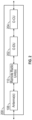
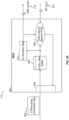
- FIG. 4A illustrates one example embodiment of a radio unit 110 in accordance with aspects of this disclosure.
- FIG. 4B illustrates one example embodiment of the connections between components of the radio unit 110 in accordance with aspects of this disclosure.
- the radio unit 110 includes a radio head 402 (also referred to as a radio frequency integrated circuit (RFIC)).
- the radio head 402 includes an input/output 404 (e.g., an Ethernet port), a data jitter buffer 406, a plurality of receive paths 408, an uplink allocation map component 410, one or more discontinuous receive control outputs 412, and one or more RF inputs 414.
- the input/output 404 is configured to receive packets 304 containing control plane data 418.
- the control plane data 418 can include uplink allocation data.
- the data jitter buffer 406 is configured to buffer the control plane data 418 to prevent jitter introduced, for example, by Ethernet communication from affecting the components downstream from the data jitter buffer 406.
- the data jitter buffer 406 can provide the buffered control plane data 418 to the receive paths 408 and the uplink allocation map component 410 at a rate expected by the receive paths 408.
- the data jitter buffer 406 may provide the control plane data 418 to the receive paths 408 and the uplink allocation map component 410 at a substantially fixed rate.
- Each of the receive paths 408 is configured to receive the control plane data 418 from the data jitter buffer 406 and amplify/convert RF signals received from one or more antenna(s) 108 based on the control plane data.
- each of the receive paths 408 can include: a low noise amplifier 420, a filter, a mixer, an analog-to-digital converter (ADC), a FFT block, etc. These components can be configured to convert the received RF signals into IQ samples that can be transmitted to the distributed unit over Ethernet.
- each of the receive paths 408 may have a fixed latency between receiving RF signals from the antenna(s) and outputting the IQ samples to the input/output 404.
- each of the receive paths 408 can be coupled to a corresponding one of the antennas 108 via a physical antenna path.
- the uplink allocation map component 410 is configured to determine or derive the discontinuous receive state in response to determining or identifying the absence of control plane data 418 received from the data jitter buffer 406. For example, the uplink allocation map component 410 can derive a first discontinuous receive state in which the corresponding receive paths 408 are to be turned off in the absence of the control plane containing data. Similarly, the uplink allocation map component 410 can derive a second discontinuous receive state in which the corresponding receive paths 408 are to be turned on in response to the control plane data 418 containing uplink allocation data indicating that there are RF signals to be received.
- the uplink allocation map component 410 can also derive the first discontinuous receive state in response to the control plane data 418 containing uplink allocation data indicating that there are no RF signals to be received.
- the uplink allocation map component 410 can then generate a plurality of discontinuous receive control signals that indicate the derived discontinuous receive states.
- Each of the discontinuous receive signals may correspond to one of the RF inputs that provide RF signals to the receive paths 408.
- the uplink allocation map component 410 can also provide the discontinuous receive control signals to the low noise amplifiers 420 in each of the corresponding receive paths 408 such that the receive paths 408 can be turned off when there are no RF signals to be received and in the absence of control plane data 418.
- the uplink allocation map component 410 can be implemented in hardware (e.g., using discrete circuity) and/or in software running on a processor or other circuit (e.g., a digital signal processor (DSP), an application specific integrated circuit (ASIC), a field programmable gate array (FPGA) or other programmable logic device).
- DSP digital signal processor
- ASIC application specific integrated circuit
- FPGA field programmable gate array
- the uplink allocation map component 410 can determine or derive the discontinuous receive state independently for each physical antenna path/receive path 408.
- the uplink allocation map component 410 can assert the discontinuous receive state (e.g., the first discontinuous receive state) in any time period for which no active allocation has been registered from the control plane data.
- the radio unit 402 can output the discontinuous receive state control signals per antenna path via the one or more discontinuous receive control outputs 412 with a configurable delay to match miscellaneous RF circuitry requirements.
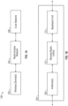
- FIG. 5 illustrates a method 500 for determining or deriving a discontinuous receive state in accordance with aspects of this disclosure.
- One or more blocks of the method 500 may be implemented, for example, by a radio unit (e.g., the radio unit 110 of FIG. 4 ) and/or an O-RAN (e.g., the O-RAN 200 of FIG. 2 ).
- a radio unit e.g., the radio unit 110 of FIG. 4
- an O-RAN e.g., the O-RAN 200 of FIG. 2 .
- an input of a radio unit can receive a plurality of packets. At least one of the packets can include control plane data. In some embodiments, the input can include an Ethernet port configured to receive the packets.
- one or more receive paths can receive one or more radio frequency signals from one or more antennas.
- the receive paths can include one or more low noise amplifiers configured to amplify the RF receive signals to a power level sufficient for communication over Ethernet to the distributed unit.
- an uplink allocation map component can receive the control plane data and determine a discontinuous receive state for each of the one or more receive paths based on the control plane data. In some embodiments, each of the one or more receive paths can be turned on and turned off based on the corresponding discontinuous receive state determined by the uplink allocation map component.
- Examples of the electronic devices can include, but are not limited to, consumer electronic products, parts of the consumer electronic products, electronic test equipment, cellular communications infrastructure such as a base station, etc.
- Examples of the electronic devices can include, but are not limited to, a mobile phone such as a smart phone, a wearable computing device such as a smart watch or an ear piece, a telephone, a television, a computer monitor, a computer, a modem, a hand-held computer, a laptop computer, a tablet computer, a personal digital assistant (PDA), a microwave, a refrigerator, a vehicular electronics system such as an automotive electronics system, a stereo system, a DVD player, a CD player, a digital music player such as an MP3 player, a radio, a camcorder, a camera such as a digital camera, a portable memory chip, a washer, a dryer, a washer/dryer, peripheral device, a clock, etc.
- the electronic devices can include unfinished products
- the words “comprise,” “comprising,” “include,” “including” and the like are to be construed in an inclusive sense, as opposed to an exclusive or exhaustive sense; that is to say, in the sense of "including, but not limited to.”
- the word “coupled,” as generally used herein, refers to two or more elements that may be either directly connected, or connected by way of one or more intermediate elements.
- the word “connected,” as generally used herein, refers to two or more elements that may be either directly connected, or connected by way of one or more intermediate elements.
- conditional language used herein such as, among others, “can,” “could,” “might,” “may,” “e.g.,” “for example,” “such as” and the like, unless specifically stated otherwise, or otherwise understood within the context as used, is generally intended to convey that certain embodiments include, while other embodiments do not include, certain features, elements and/or states.
- conditional language is not generally intended to imply that features, elements and/or states are in any way required for one or more embodiments or whether these features, elements and/or states are included or are to be performed in any particular embodiment.
Landscapes
- Engineering & Computer Science (AREA)
- Computer Networks & Wireless Communication (AREA)
- Signal Processing (AREA)
- Mobile Radio Communication Systems (AREA)
Abstract
Description
- Any and all applications for which a foreign or domestic priority claim is identified in the Application Data Sheet as filed with the present application are hereby incorporated by reference under 37 CFR 1.57.
- This application claims the benefit of priority of
U.S. Provisional Application No. 63/484,344, filed February 10, 2023 U.S. Non-Provisional Application No. 18/423,074, filed January 25, 2024 - The disclosed technology relates generally to radios and more particularly to discontinuous receive signals used by Ethernet based radios.
- Open radio access network (O-RAN) is a communication standard that can employ Ethernet for communications between an O-RAN radio unit (O-RU) and an O-RAN distributed unit (O-DU).
- In one aspect, a radio unit for radio frequency communications, comprising: an input configured to receive a plurality of packets, at least one of the packets including control plane data; one or more receive paths configured to receive one or more radio frequency signals from one or more antennas; and an uplink allocation map component configured to receive the control plane data and determine a discontinuous receive state for each of the one or more receive paths based on the control plane data.
- In some embodiments, each of the one or more receive paths is further configured to turn on and turn off based on the corresponding discontinuous receive state.
- In some embodiments, the radio unit further comprises: a data jitter buffer configured to receive the control plane data from the input and to provide the control plane data to each of the one or more receive paths and the uplink allocation map component.
- In some embodiments, the data jitter buffer is further configured to provide the control plane data at a substantially fixed rate.
- In some embodiments, the uplink allocation map component is further configured to set the discontinuous receive state in one of a first discontinuous receive state in which the corresponding receive path is to be turned off in response to absence of the control plane data or a second discontinuous receive state in which the corresponding receive path is to be turned on in response to the control plane data indicating that there are radio frequency signals to be received.
- In some embodiments, each of the one or more receive paths comprises a low noise amplifier coupled to a corresponding one of the one or more antennas, and the uplink allocation map component is further configured to provide the discontinuous receive states to the one or more low noise amplifiers.
- In some embodiments, the input is further configured to receive the packets from a distributed unit via Ethernet.
- Another aspect is a method of determining a discontinuous receive state within a radio unit, comprising: receiving a plurality of packets at an input of the radio unit, at least one of the packets including control plane data; receiving, at one or more receive paths, one or more radio frequency signals from one or more antennas; and determining a discontinuous receive state for each of the one or more receive paths based on the control plane data.
- In some embodiments, the method further comprises: turning on and turning off each of the one or more receive paths based on the corresponding discontinuous receive state.
- In some embodiments, the method further comprises: receiving the control plane data at a data jitter buffer from the input; and providing the control plane data from the data jitter buffer to each of the one or more receive paths.
- In some embodiments, the method further comprises: providing the control plane data from the data jitter buffer at a substantially fixed rate.
- In some embodiments, the method further comprises setting the discontinuous receive state in one of: a first discontinuous receive state in which the corresponding receive path is to be turned off in response to absence of the control plane data; and a second discontinuous receive state in which the corresponding receive path is to be turned on in response to the control plane data indicating that there are radio frequency signals to be received.
- In some embodiments, the method further comprises: providing the discontinuous receive states to one or more low noise amplifiers coupled to the one or more antennas.
- In some embodiments, the receiving of the plurality of packets includes receiving the packets from a distributed unit via Ethernet.
- Yet another aspect is an open radio access network (O-RAN), comprising: a distributed unit configured to output a plurality of packets, at least one of the packets including control plane data; one or more antennas configured to receive radio frequency (RF) signals; and a radio unit configured to receive the packets from the distributed unit and to receive the RF signals from the one or more antennas based on the control plane data; wherein the radio unit comprises: an input configured to receive the packets from the distributed unit; one or more receive paths configured to receive the RF signals from the one or more antennas; and an uplink allocation map component configured to receive the control plane data and determine a discontinuous receive state for each of the one or more receive paths based on the control plane data.
- In some embodiments, each of the one or more receive paths is further configured to turn on and turn off based on the corresponding discontinuous receive state.
- In some embodiments, the radio unit further comprises: a data jitter buffer configured to receive the control plane data from the input and to provide the control plane data to each of the one or more receive paths and the uplink allocation map component.
- In some embodiments, the data jitter buffer is further configured to provide the control plane data at a substantially fixed rate.
- In some embodiments, the uplink allocation map component is further configured to set the discontinuous receive state in one of a first discontinuous receive state in which the corresponding receive path is to be turned off in response to absence of the control plane data or a second discontinuous receive state in which the corresponding receive path is to be turned on in response to the control plane data indicating that there are radio frequency signals to be received.
- In some embodiments, each of the one or more receive paths comprises a low noise amplifier coupled to a corresponding one of the one or more antennas, and the uplink allocation map component is further configured to provide the discontinuous receive states to the one or more low noise amplifiers.
- These drawings and the associated description herein are provided to illustrate specific embodiments of the invention and are not intended to be limiting.
-
FIG. 1A illustrates an example wireless telecommunication system. -
FIG. 1B illustrates an example of a RAN. -
FIG. 2 illustrates an example of an O-RAN which can be used as part of a telecommunication system. -
FIG. 3 provides an illustration of the communications between a distributed unit and a radio unit when transmitting radio frequency signals using an O-RAN system. -
FIG. 4A illustrates one example embodiment of a radio unit in accordance with aspects of this disclosure. -
FIG. 4B illustrates one example embodiment of the connections between components of the radio unit in accordance with aspects of this disclosure. -
FIG. 5 illustrates a method for deriving a discontinuous receive state in accordance with aspects of this disclosure. - Various aspects of the novel systems, apparatuses, and methods are described more fully hereinafter with reference to the accompanying drawings. Aspects of this disclosure may, however, be embodied in many different forms and should not be construed as limited to any specific structure or function presented throughout this disclosure. Rather, these aspects are provided so that this disclosure will be thorough and complete, and will fully convey the scope of the disclosure to those skilled in the art. Based on the teachings herein, one skilled in the art should appreciate that the scope of the disclosure is intended to cover any aspect of the novel systems, apparatuses, and methods disclosed herein, whether implemented independently of or combined with any other aspect. For example, an apparatus may be implemented or a method may be practiced using any number of the aspects set forth herein. In addition, the scope is intended to encompass such an apparatus or method which is practiced using other structure, functionality, or structure and functionality in addition to or other than the various aspects set forth herein. It should be understood that any aspect disclosed herein may be embodied by one or more elements of a claim.
- Although particular aspects are described herein, many variations and permutations of these aspects fall within the scope of the disclosure. Although some benefits and advantages of the preferred aspects are mentioned, the scope of the disclosure is not intended to be limited to particular benefits, uses, or objectives. Rather, aspects of the disclosure are intended to be broadly applicable to different wired and wireless technologies, system configurations, networks, including optical networks, hard disks, and transmission protocols, some of which are illustrated by way of example in the figures and in the following description of the preferred aspects. The detailed description and drawings are merely illustrative of the disclosure rather than limiting, the scope of the disclosure being defined by the appended claims and equivalents thereof.
- In this description, reference is made to the drawings where like reference numerals can indicate identical or functionally similar elements. It will be understood that elements illustrated in the figures are not necessarily drawn to scale. Moreover, it will be understood that certain embodiments can include more elements than illustrated in a drawing and/or a subset of the elements illustrated in a drawing. Further, some embodiments can incorporate any suitable combination of features from two or more drawings.
-
FIG. 1A illustrates an examplewireless telecommunication system 100. Thewireless telecommunication system 100 includes one or more wireless device(s) 102, a radio access network (RAN) 104, and a core network (CN) 106. As used herein, a RAN 104 generally refers to a network used as a part of thewireless telecommunication system 100. The RAN 104 can be used to connect the one or more wireless device(s) 102, such as mobile phones, to theCN 106 of thetelecommunication system 100. -
FIG. 1B illustrates an example of a RAN 104. In some embodiments, theRAN 104 can include a baseband unit (BBU) 112 that is connected to one or more remote radio units (RRUs) 110 positioned near one or more antenna(s) 108. TheBBU 112 can be configured to communicate with theCN 106, while the antenna(s) 108 can be configured to communicate with the wireless device(s) 102. -
FIG. 2 illustrates an example of an O-RAN 200 which can be used as part of a telecommunication system. As used herein, O-RAN 200 generally refers to a type of RAN that, among other things, can employ Ethernet for communications between components of the O-RAN 200. In some embodiments, the BBU from a RAN can be replaced with two components in the O-RAN 200, a distributed unit (DU, also referred to as O-DU) 202 and a central unit (CU, also referred to as O-CU) 204. In some embodiments, the distributedunit 202 and thecentral unit 204 can be connected and communicate via Ethernet. - The O-
RAN 200 can communication distinct control plane (CP) and user plane (UP) information with the radio unit (RU, also referred to as O-RU) 110 to be transmitted or received using radio frequency (RF) signals. The control plane can be used to communicate the presence or the absence of downlink data scheduling. The user plane can provide the data to be transmitted. As described herein, theradio unit 110 can include RF circuitry configured to amplify and/or convert the user plane data into RF signals that can be transmitted by the one or more antenna(s) 108. In some embodiments, the RF circuity can include, for example: a fast Fourier transform (FFT) block, a digital-to-analog converter (DAC), a mixer, a variable gain amplifier, a phase shifter, a power amplifier, etc. The transmit paths may use relatively large amounts of power to amplify the RF signals to powers sufficient for the distances used for wireless RF communications, and thus, turning off transmit paths when they are not currently being used for RF communications can reduce power consumption of the O-RAN 200. - The use of Ethernet within the O-
RAN 200 can introduce certain challenges. For example, since Ethernet is a packet-based communication standard, it is possible for individual packets to be lost. This can lead to undesirable functionality of the system when a component, such as theradio unit 110, does not receive the expected lost data packets. - The O-
RAN 200 can also employ discontinuous transmit (DTX) to reduce power consumption when radio frequency signals are not being transmitted by a givenantenna 108 or channel of theradio unit 110. The O-RAN 200 can also employ discontinuous receive (DRX) to protect sensitive components when radio frequency signals are not being received by a givenantenna 108 or channel of theradio unit 110. -
FIG. 3 provides an illustration of the communications between a distributedunit 202 and aradio unit 110 when receiving radio frequency signals using an O-RAN 200 system. The distributedunit 202 can provide a discontinuous receive signal, or discontinuous receive signal, which can be used by theradio unit 110 to turn off certain components of the RF circuitry for a corresponding channel or transmit path of theradio unit 110 at times when there is no data (e.g., data in the user plane) to be wirelessly received. - The state of the discontinuous receive signal can be determined or derived directly from control information such as a pre-determined schedule (for instance, a time division duplexing or TDD transmit/receive schedule) or real time control information. In the context of O-RAN, the Ethernet based network can provide the control plane and user plane information to
radio units 110, for example, via the distributed unit202. The control plane can be used to signal or indicate the absence or presence of uplink data scheduling to follow in the user plane. The user plane can provide the actual data being received. - However, relying on a control or a pre-determined schedule to drive discontinuous receive signaling may be less accurate and can introduce a risk of damaging equipment or components in the receive path since the receiver circuitry may remain active in the absence of control information directing the receiver circuity to turn off. For example, when using direct real-time control for closely placed
radio units 110, a packet instructing the receiver circuitry of aparticular radio unit 110 to turn off can be lost, resulting in the receiver circuitry erroneously remaining on while nearby high power transmitters fromother radio units 110 are transmitting. - Accordingly, the lack of control information is especially relevant in packet-based networks, such as Ethernet, where control packets may be dropped. This can result in the
radio unit 110 being instructed to maintain an active receive path due to the packets containing the control plane information with instructions to turn the receive path off being lost. The receive paths may use relatively sensitive components (e.g., a low noise amplifier (LNA)) designed to receive relatively weak signals with low signal-to-noise ratios. If the receive path remains active while a transmit path in thesame radio unit 110 or anotherradio unit 110 begins transmitting radio frequency signals, the receive path may receive signals having a much greater strength than the receive path is designed to handle, which can result in damage to component(s) on the receive path and/or receiver desense. -
FIG. 3 illustrates one example situation in which packet loss may result in one or more receive paths remaining on when a packet containing control plane data is lost. In particular, the distributedunit 202 can providecontrol plane messages 302 to theradio unit 110 to instruct one or more receive paths of theradio unit 110 to turn off. In certain situations, the distributedunit 202 may be lost as illustrated inFIG. 3 . Since in the situation illustrated inFIG. 3 , theradio unit 110 did not receive thecontrol plane message 302, theradio unit 110 may maintain the one or more receive paths on in a receive state, which may make the receive paths vulnerable to damage as discussed above. - There are different techniques for deriving discontinuous receive control. In one embodiment, the O-RAN standard provides a standards optional method of relying on control information for explicit notification of discontinuous receive periods. However, this is not autonomous and may be vulnerable to packet disruption on the fronthaul network the
radio unit 110 is linked to. - Aspects of this disclosure relate to systems and techniques for determining or deriving the discontinuous receive state directly from the absence of control plane data. By deriving the discontinuous receive state directly from the absence of control plane data, in circumstances such as congestion in the Ethernet based network that may cause control plane data outages, the
radio unit 110 can assert the discontinuous receive state to prevent damage or inoperability to one or more receive paths. In contrast, in implementations in which the discontinuous receive state is derived from a pre-determined schedule or from control plane information, theradio unit 110 may have maintained an active receive state even when no control plane data is received by theradio unit 110 due to packet loss. -
FIG. 4A illustrates one example embodiment of aradio unit 110 in accordance with aspects of this disclosure.FIG. 4B illustrates one example embodiment of the connections between components of theradio unit 110 in accordance with aspects of this disclosure. With reference toFIGs. 4A and4B , theradio unit 110 includes a radio head 402 (also referred to as a radio frequency integrated circuit (RFIC)). Theradio head 402 includes an input/output 404 (e.g., an Ethernet port), adata jitter buffer 406, a plurality of receivepaths 408, an uplinkallocation map component 410, one or more discontinuous receivecontrol outputs 412, and one ormore RF inputs 414. The input/output 404 is configured to receivepackets 304 containingcontrol plane data 418. Thecontrol plane data 418 can include uplink allocation data. - The data jitter
buffer 406 is configured to buffer thecontrol plane data 418 to prevent jitter introduced, for example, by Ethernet communication from affecting the components downstream from the data jitterbuffer 406. The data jitterbuffer 406 can provide the bufferedcontrol plane data 418 to the receivepaths 408 and the uplinkallocation map component 410 at a rate expected by the receivepaths 408. In some embodiments, thedata jitter buffer 406 may provide thecontrol plane data 418 to the receivepaths 408 and the uplinkallocation map component 410 at a substantially fixed rate. - Each of the receive
paths 408 is configured to receive thecontrol plane data 418 from the data jitterbuffer 406 and amplify/convert RF signals received from one or more antenna(s) 108 based on the control plane data. In some embodiments, each of the receivepaths 408 can include: alow noise amplifier 420, a filter, a mixer, an analog-to-digital converter (ADC), a FFT block, etc. These components can be configured to convert the received RF signals into IQ samples that can be transmitted to the distributed unit over Ethernet. In some embodiments, each of the receivepaths 408 may have a fixed latency between receiving RF signals from the antenna(s) and outputting the IQ samples to the input/output 404. In some embodiments, each of the receivepaths 408 can be coupled to a corresponding one of theantennas 108 via a physical antenna path. - The uplink
allocation map component 410 is configured to determine or derive the discontinuous receive state in response to determining or identifying the absence ofcontrol plane data 418 received from the data jitterbuffer 406. For example, the uplinkallocation map component 410 can derive a first discontinuous receive state in which the corresponding receivepaths 408 are to be turned off in the absence of the control plane containing data. Similarly, the uplinkallocation map component 410 can derive a second discontinuous receive state in which the corresponding receivepaths 408 are to be turned on in response to thecontrol plane data 418 containing uplink allocation data indicating that there are RF signals to be received. The uplinkallocation map component 410 can also derive the first discontinuous receive state in response to thecontrol plane data 418 containing uplink allocation data indicating that there are no RF signals to be received. The uplinkallocation map component 410 can then generate a plurality of discontinuous receive control signals that indicate the derived discontinuous receive states. Each of the discontinuous receive signals may correspond to one of the RF inputs that provide RF signals to the receivepaths 408. The uplinkallocation map component 410 can also provide the discontinuous receive control signals to thelow noise amplifiers 420 in each of the corresponding receivepaths 408 such that the receivepaths 408 can be turned off when there are no RF signals to be received and in the absence ofcontrol plane data 418. - Depending on the embodiment, the uplink
allocation map component 410 can be implemented in hardware (e.g., using discrete circuity) and/or in software running on a processor or other circuit (e.g., a digital signal processor (DSP), an application specific integrated circuit (ASIC), a field programmable gate array (FPGA) or other programmable logic device). - By extracting the time for the start and the end of uplink RF allocations from the control plane data, the uplink
allocation map component 410 can determine or derive the discontinuous receive state independently for each physical antenna path/receivepath 408. The uplinkallocation map component 410 can assert the discontinuous receive state (e.g., the first discontinuous receive state) in any time period for which no active allocation has been registered from the control plane data. Theradio unit 402 can output the discontinuous receive state control signals per antenna path via the one or more discontinuous receivecontrol outputs 412 with a configurable delay to match miscellaneous RF circuitry requirements. -
FIG. 5 illustrates amethod 500 for determining or deriving a discontinuous receive state in accordance with aspects of this disclosure. One or more blocks of themethod 500 may be implemented, for example, by a radio unit (e.g., theradio unit 110 ofFIG. 4 ) and/or an O-RAN (e.g., the O-RAN 200 ofFIG. 2 ). - At
block 502, an input of a radio unit can receive a plurality of packets. At least one of the packets can include control plane data. In some embodiments, the input can include an Ethernet port configured to receive the packets. - At
block 504, one or more receive paths can receive one or more radio frequency signals from one or more antennas. The receive paths can include one or more low noise amplifiers configured to amplify the RF receive signals to a power level sufficient for communication over Ethernet to the distributed unit. Atblock 506, an uplink allocation map component can receive the control plane data and determine a discontinuous receive state for each of the one or more receive paths based on the control plane data. In some embodiments, each of the one or more receive paths can be turned on and turned off based on the corresponding discontinuous receive state determined by the uplink allocation map component. - In the foregoing, it will be appreciated that any feature of any one of the embodiments can be combined or substituted with any other feature of any other one of the embodiments.
- Aspects of this disclosure can be implemented in various electronic devices. Examples of the electronic devices can include, but are not limited to, consumer electronic products, parts of the consumer electronic products, electronic test equipment, cellular communications infrastructure such as a base station, etc. Examples of the electronic devices can include, but are not limited to, a mobile phone such as a smart phone, a wearable computing device such as a smart watch or an ear piece, a telephone, a television, a computer monitor, a computer, a modem, a hand-held computer, a laptop computer, a tablet computer, a personal digital assistant (PDA), a microwave, a refrigerator, a vehicular electronics system such as an automotive electronics system, a stereo system, a DVD player, a CD player, a digital music player such as an MP3 player, a radio, a camcorder, a camera such as a digital camera, a portable memory chip, a washer, a dryer, a washer/dryer, peripheral device, a clock, etc. Further, the electronic devices can include unfinished products.
- Unless the context clearly requires otherwise, throughout the description and the claims, the words "comprise," "comprising," "include," "including" and the like are to be construed in an inclusive sense, as opposed to an exclusive or exhaustive sense; that is to say, in the sense of "including, but not limited to." The word "coupled," as generally used herein, refers to two or more elements that may be either directly connected, or connected by way of one or more intermediate elements. Likewise, the word "connected," as generally used herein, refers to two or more elements that may be either directly connected, or connected by way of one or more intermediate elements. Additionally, the words "herein," "above," "below," and words of similar import, when used in this application, shall refer to this application as a whole and not to any particular portions of this application. Where the context permits, words in the above Detailed Description using the singular or plural number may also include the plural or singular number, respectively. The word "or" in reference to a list of two or more items, that word covers all of the following interpretations of the word: any of the items in the list, all of the items in the list, and any combination of the items in the list.
- Moreover, conditional language used herein, such as, among others, "can," "could," "might," "may," "e.g.," "for example," "such as" and the like, unless specifically stated otherwise, or otherwise understood within the context as used, is generally intended to convey that certain embodiments include, while other embodiments do not include, certain features, elements and/or states. Thus, such conditional language is not generally intended to imply that features, elements and/or states are in any way required for one or more embodiments or whether these features, elements and/or states are included or are to be performed in any particular embodiment.
- While certain embodiments have been described, these embodiments have been presented by way of example only, and are not intended to limit the scope of the disclosure. Indeed, the novel apparatus, methods, and systems described herein may be embodied in a variety of other forms; furthermore, various omissions, substitutions and changes in the form of the methods and systems described herein may be made without departing from the spirit of the disclosure. For example, while blocks are presented in a given arrangement, alternative embodiments may perform similar functionalities with different components and/or circuit topologies, and some blocks may be deleted, moved, added, subdivided, combined, and/or modified. Each of these blocks may be implemented in a variety of different ways. Any suitable combination of the elements and acts of the various embodiments described above can be combined to provide further embodiments. The various features and processes described above may be implemented independently of one another, or may be combined in various ways. All possible combinations and subcombinations of features of this disclosure are intended to fall within the scope of this disclosure.
- By way of non-limiting example, some aspects of the disclosure are set out in the following numbered clauses.
- 1. A radio unit for radio frequency communications, comprising:
- an input configured to receive a plurality of packets, at least one of the packets including control plane data;
- one or more receive paths configured to receive one or more radio frequency signals from one or more antennas; and
- an uplink allocation map component configured to receive the control plane data and determine a discontinuous receive state for each of the one or more receive paths based on the control plane data.
- 2. The radio unit of
Clause 1, wherein each of the one or more receive paths is further configured to turn on and turn off based on the corresponding discontinuous receive state. - 3. The radio unit of
Clause 1 or 2, further comprising:
a data jitter buffer configured to receive the control plane data from the input and to provide the control plane data to each of the one or more receive paths and the uplink allocation map component. - 4. The radio unit of Clause 3, wherein the data jitter buffer is further configured to provide the control plane data at a substantially fixed rate.
- 5. The radio unit of any preceding Clause, wherein the uplink allocation map component is further configured to set the discontinuous receive state in one of a first discontinuous receive state in which the corresponding receive path is to be turned off in response to absence of the control plane data or a second discontinuous receive state in which the corresponding receive path is to be turned on in response to the control plane data indicating that there are radio frequency signals to be received.
- 6. The radio unit of any preceding Clause, wherein:
- each of the one or more receive paths comprises a low noise amplifier coupled to a corresponding one of the one or more antennas, and
- the uplink allocation map component is further configured to provide the discontinuous receive states to the one or more low noise amplifiers.
- 7. The radio unit of any preceding Clause, wherein the input is further configured to receive the packets from a distributed unit via Ethernet.
- 8. A method of determining a discontinuous receive state within a radio unit, comprising:
- receiving a plurality of packets at an input of the radio unit, at least one of the packets including control plane data;
- receiving, at one or more receive paths, one or more radio frequency signals from one or more antennas; and
- determining a discontinuous receive state for each of the one or more receive paths based on the control plane data.
- 9. The method of Clause 8, further comprising:
turning on and turning off each of the one or more receive paths based on the corresponding discontinuous receive state. - 10. The method of Clause 8 or 9, further comprising:
- receiving the control plane data at a data jitter buffer from the input; and
- providing the control plane data from the data jitter buffer to each of the one or more receive paths.
- 11. The method of Clause 10, further comprising:
providing the control plane data from the data jitter buffer at a substantially fixed rate. - 12. The method of any of Clauses 8 to 11, further comprising setting the discontinuous receive state in one of:
- a first discontinuous receive state in which the corresponding receive path is to be turned off in response to absence of the control plane data; and
- a second discontinuous receive state in which the corresponding receive path is to be turned on in response to the control plane data indicating that there are radio frequency signals to be received.
- 13. The method of any of Clauses 8 to 12, further comprising:
providing the discontinuous receive states to one or more low noise amplifiers coupled to the one or more antennas. - 14. The method of any of Clauses 8 to 13, wherein the receiving of the plurality of packets includes receiving the packets from a distributed unit via Ethernet.
- 15. An open radio access network (O-RAN), comprising:
- a distributed unit configured to output a plurality of packets, at least one of the packets including control plane data;
- one or more antennas configured to receive radio frequency (RF) signals; and
- a radio unit configured to receive the packets from the distributed unit and to receive the RF signals from the one or more antennas based on the control plane data;
- wherein the radio unit comprises:
- an input configured to receive the packets from the distributed unit;
- one or more receive paths configured to receive the RF signals from the one or more antennas; and
- an uplink allocation map component configured to receive the control plane data and determine a discontinuous receive state for each of the one or more receive paths based on the control plane data.
- 16. The O-RAN of Clause 15, wherein each of the one or more receive paths is further configured to turn on and turn off based on the corresponding discontinuous receive state.
- 17. The O-RAN of Clause 15 or 16, wherein the radio unit further comprises:
a data jitter buffer configured to receive the control plane data from the input and to provide the control plane data to each of the one or more receive paths and the uplink allocation map component. - 18. The O-RAN of Clause 17, wherein the data jitter buffer is further configured to provide the control plane data at a substantially fixed rate.
- 19. The O-RAN of any of Clauses 15 to 18, wherein the uplink allocation map component is further configured to set the discontinuous receive state in one of a first discontinuous receive state in which the corresponding receive path is to be turned off in response to absence of the control plane data or a second discontinuous receive state in which the corresponding receive path is to be turned on in response to the control plane data indicating that there are radio frequency signals to be received.
- 20. The O-RAN of any of Clauses 15 to 19, wherein:
- each of the one or more receive paths comprises a low noise amplifier coupled to a corresponding one of the one or more antennas, and
- the uplink allocation map component is further configured to provide the discontinuous receive states to the one or more low noise amplifiers.
Claims (15)
- A radio unit for radio frequency communications, comprising:an input configured to receive a plurality of packets, at least one of the packets including control plane data;one or more receive paths configured to receive one or more radio frequency signals from one or more antennas; andan uplink allocation map component configured to receive the control plane data and determine a discontinuous receive state for each of the one or more receive paths based on the control plane data.
- The radio unit of Claim 1, wherein each of the one or more receive paths is further configured to turn on and turn off based on the corresponding discontinuous receive state.
- The radio unit of Claim 1 or 2, further comprising:
a data jitter buffer configured to receive the control plane data from the input and to provide the control plane data to each of the one or more receive paths and the uplink allocation map component. - The radio unit of Claim 3, wherein the data jitter buffer is further configured to provide the control plane data at a substantially fixed rate.
- The radio unit of any preceding Claim, wherein the uplink allocation map component is further configured to set the discontinuous receive state in one of a first discontinuous receive state in which the corresponding receive path is to be turned off in response to absence of the control plane data or a second discontinuous receive state in which the corresponding receive path is to be turned on in response to the control plane data indicating that there are radio frequency signals to be received.
- The radio unit of any preceding Claim, wherein:each of the one or more receive paths comprises a low noise amplifier coupled to a corresponding one of the one or more antennas, andthe uplink allocation map component is further configured to provide the discontinuous receive states to the one or more low noise amplifiers.
- The radio unit of any preceding Claim, wherein the input is further configured to receive the packets from a distributed unit via Ethernet.
- A method of determining a discontinuous receive state within a radio unit, comprising:receiving a plurality of packets at an input of the radio unit, at least one of the packets including control plane data;receiving, at one or more receive paths, one or more radio frequency signals from one or more antennas; anddetermining a discontinuous receive state for each of the one or more receive paths based on the control plane data.
- The method of Claim 8, further comprising:
turning on and turning off each of the one or more receive paths based on the corresponding discontinuous receive state. - The method of Claim 8 or 9, further comprising:receiving the control plane data at a data jitter buffer from the input; andproviding the control plane data from the data jitter buffer to each of the one or more receive paths.
- The method of Claim 10, further comprising:
providing the control plane data from the data jitter buffer at a substantially fixed rate. - The method of any of Claims 8 to 11, further comprising setting the discontinuous receive state in one of:a first discontinuous receive state in which the corresponding receive path is to be turned off in response to absence of the control plane data; anda second discontinuous receive state in which the corresponding receive path is to be turned on in response to the control plane data indicating that there are radio frequency signals to be received.
- The method of any of Claims 8 to 12, further comprising:
providing the discontinuous receive states to one or more low noise amplifiers coupled to the one or more antennas. - The method of any of Claims 8 to 13, wherein the receiving of the plurality of packets includes receiving the packets from a distributed unit via Ethernet.
- An open radio access network (O-RAN), comprising:a distributed unit configured to output a plurality of packets, at least one of the packets including control plane data;one or more antennas configured to receive radio frequency (RF) signals; and
a radio unit in accordance with any of Claims 1 to 7, configured to receive the packets from the distributed unit and to receive the RF signals from the one or more antennas based on the control plane data.
Applications Claiming Priority (2)
| Application Number | Priority Date | Filing Date | Title |
|---|---|---|---|
| US202363484344P | 2023-02-10 | 2023-02-10 | |
| US18/423,074 US20240276588A1 (en) | 2023-02-10 | 2024-01-25 | Autonomous determination of discontinuous receive opportunities by ethernet based radios |
Publications (2)
| Publication Number | Publication Date |
|---|---|
| EP4415434A1 true EP4415434A1 (en) | 2024-08-14 |
| EP4415434B1 EP4415434B1 (en) | 2026-04-01 |
Family
ID=89843374
Family Applications (1)
| Application Number | Title | Priority Date | Filing Date |
|---|---|---|---|
| EP24155644.8A Active EP4415434B1 (en) | 2023-02-10 | 2024-02-02 | Drx in ethernet based radios |
Country Status (2)
| Country | Link |
|---|---|
| US (1) | US20240276588A1 (en) |
| EP (1) | EP4415434B1 (en) |
Citations (2)
| Publication number | Priority date | Publication date | Assignee | Title |
|---|---|---|---|---|
| US20140098694A1 (en) * | 2012-10-09 | 2014-04-10 | Apple Inc. | Dynamic receive diversity selection for lte |
| US20170373890A1 (en) * | 2015-03-11 | 2017-12-28 | Phluido, Inc. | Remote Radio Unit with Adaptive Fronthaul Link for a Distributed Radio Access Network |
-
2024
- 2024-01-25 US US18/423,074 patent/US20240276588A1/en active Pending
- 2024-02-02 EP EP24155644.8A patent/EP4415434B1/en active Active
Patent Citations (2)
| Publication number | Priority date | Publication date | Assignee | Title |
|---|---|---|---|---|
| US20140098694A1 (en) * | 2012-10-09 | 2014-04-10 | Apple Inc. | Dynamic receive diversity selection for lte |
| US20170373890A1 (en) * | 2015-03-11 | 2017-12-28 | Phluido, Inc. | Remote Radio Unit with Adaptive Fronthaul Link for a Distributed Radio Access Network |
Non-Patent Citations (1)
| Title |
|---|
| SZIGETI TIM ET AL: "End-to-end QoS network design", 1 January 2005 (2005-01-01), pages 1 - 5, XP093178904, ISBN: 978-1-58705-176-0, Retrieved from the Internet <URL:https://www.amazon.com/End-End-QoS-Network-Design/dp/1587143690> [retrieved on 20240627] * |
Also Published As
| Publication number | Publication date |
|---|---|
| US20240276588A1 (en) | 2024-08-15 |
| EP4415434B1 (en) | 2026-04-01 |
Similar Documents
| Publication | Publication Date | Title |
|---|---|---|
| US10582557B2 (en) | RFFE for dual connectivity | |
| US10505700B1 (en) | Reducing intermodulation distortion for intra-band dual connectivity | |
| US20130196673A1 (en) | Mobile wireless communications device with wireless local area network and cellular scheduling and related methods | |
| JP2016026446A (en) | System and method for clear channel assessment that supports simultaneous transmission by multiple wireless protocols | |
| WO2016023002A1 (en) | Front end architecture for intermittent emissions and/or coexistence specifications | |
| US10827431B2 (en) | Receiver front-end power consumption reduction via linearity and sensitivity adaptation | |
| EP2624653A1 (en) | Mobile wireless communications device with wireless local area network and cellular scheduling and related methods | |
| US7711341B2 (en) | Multimode receiver control method and apparatus | |
| US11800405B2 (en) | Systems and methods for cooperative communication using interfering signals | |
| WO2022204874A1 (en) | Power consumption control method, and wireless local area network communication apparatus | |
| US20240276588A1 (en) | Autonomous determination of discontinuous receive opportunities by ethernet based radios | |
| EP4418807A1 (en) | Autonomous determination of discontinuous transmit opportunities by ethernet based radios | |
| US11877245B2 (en) | Apparatus, system, and method for enhanced mobile station power transmission | |
| JP7697077B2 (en) | Autonomous Determination of Discontinuous Reception Opportunities with Ethernet-Based Radios | |
| US20120099496A1 (en) | Methods circuits devices and systems for collocating a digital video receiver with a digital data transceiver | |
| JP7697076B2 (en) | Autonomous Determination of Discontinuous Transmission Opportunities over Ethernet-Based Radios | |
| US9036557B2 (en) | Wireless communication device with both a wireless transceiver and a wireless paging receiver | |
| US10171124B2 (en) | Low noise amplifier arbiter for license assisted access systems | |
| US20250260506A1 (en) | Jamming signal rejection | |
| US12483287B1 (en) | Low-rate wireless personal area network (LR-WPAN) preamble detection in the presence of concurrently transmitted wireless signals | |
| WO2025231888A1 (en) | Srs configuration | |
| US20200413332A1 (en) | Communication Method, Signal Transmitter Circuit, and Signal Receiver Circuit Capable of Reducing Power Consumption | |
| GB2460112A (en) | Controlling transmission diversity by delaying a signal on a second transmit path relative to a first transmit path | |
| WO2024221243A1 (en) | Beam determining method and apparatus, and storage medium | |
| CN116667872A (en) | Communication signal transmission method, device, multiple-input multiple-output circuit and equipment |
Legal Events
| Date | Code | Title | Description |
|---|---|---|---|
| PUAI | Public reference made under article 153(3) epc to a published international application that has entered the european phase |
Free format text: ORIGINAL CODE: 0009012 |
|
| STAA | Information on the status of an ep patent application or granted ep patent |
Free format text: STATUS: REQUEST FOR EXAMINATION WAS MADE |
|
| 17P | Request for examination filed |
Effective date: 20240202 |
|
| AK | Designated contracting states |
Kind code of ref document: A1 Designated state(s): AL AT BE BG CH CY CZ DE DK EE ES FI FR GB GR HR HU IE IS IT LI LT LU LV MC ME MK MT NL NO PL PT RO RS SE SI SK SM TR |
|
| REG | Reference to a national code |
Ref country code: DE Ref legal event code: R079 Free format text: PREVIOUS MAIN CLASS: H04W0052380000 Ipc: H04W0076280000 Ref document number: 602024003502 Country of ref document: DE |
|
| GRAP | Despatch of communication of intention to grant a patent |
Free format text: ORIGINAL CODE: EPIDOSNIGR1 |
|
| STAA | Information on the status of an ep patent application or granted ep patent |
Free format text: STATUS: GRANT OF PATENT IS INTENDED |
|
| RIC1 | Information provided on ipc code assigned before grant |
Ipc: H04W 76/28 20180101AFI20250813BHEP Ipc: H04W 76/15 20180101ALN20250813BHEP |
|
| INTG | Intention to grant announced |
Effective date: 20250826 |
|
| GRAS | Grant fee paid |
Free format text: ORIGINAL CODE: EPIDOSNIGR3 |
|
| GRAA | (expected) grant |
Free format text: ORIGINAL CODE: 0009210 |
|
| STAA | Information on the status of an ep patent application or granted ep patent |
Free format text: STATUS: THE PATENT HAS BEEN GRANTED |
|
| AK | Designated contracting states |
Kind code of ref document: B1 Designated state(s): AL AT BE BG CH CY CZ DE DK EE ES FI FR GB GR HR HU IE IS IT LI LT LU LV MC ME MK MT NL NO PL PT RO RS SE SI SK SM TR |
|
| REG | Reference to a national code |
Ref country code: CH Ref legal event code: F10 Free format text: ST27 STATUS EVENT CODE: U-0-0-F10-F00 (AS PROVIDED BY THE NATIONAL OFFICE) Effective date: 20260401 Ref country code: GB Ref legal event code: FG4D |
|
| REG | Reference to a national code |
Ref country code: DE Ref legal event code: R096 Ref document number: 602024003502 Country of ref document: DE |
|
| REG | Reference to a national code |
Ref country code: IE Ref legal event code: FG4D |