EP4415374A1 - Adaptive frame rate for low power slam in xr - Google Patents
Adaptive frame rate for low power slam in xr Download PDFInfo
- Publication number
- EP4415374A1 EP4415374A1 EP24156404.6A EP24156404A EP4415374A1 EP 4415374 A1 EP4415374 A1 EP 4415374A1 EP 24156404 A EP24156404 A EP 24156404A EP 4415374 A1 EP4415374 A1 EP 4415374A1
- Authority
- EP
- European Patent Office
- Prior art keywords
- slam
- frame rate
- camera sensor
- image sequence
- slam device
- Prior art date
- Legal status (The legal status is an assumption and is not a legal conclusion. Google has not performed a legal analysis and makes no representation as to the accuracy of the status listed.)
- Pending
Links
Images






Classifications
-
- H—ELECTRICITY
- H04—ELECTRIC COMMUNICATION TECHNIQUE
- H04N—PICTORIAL COMMUNICATION, e.g. TELEVISION
- H04N23/00—Cameras or camera modules comprising electronic image sensors; Control thereof
- H04N23/60—Control of cameras or camera modules
-
- G—PHYSICS
- G06—COMPUTING OR CALCULATING; COUNTING
- G06T—IMAGE DATA PROCESSING OR GENERATION, IN GENERAL
- G06T7/00—Image analysis
- G06T7/50—Depth or shape recovery
- G06T7/55—Depth or shape recovery from multiple images
- G06T7/579—Depth or shape recovery from multiple images from motion
-
- G—PHYSICS
- G02—OPTICS
- G02B—OPTICAL ELEMENTS, SYSTEMS OR APPARATUS
- G02B27/00—Optical systems or apparatus not provided for by any of the groups G02B1/00 - G02B26/00, G02B30/00
- G02B27/0093—Optical systems or apparatus not provided for by any of the groups G02B1/00 - G02B26/00, G02B30/00 with means for monitoring data relating to the user, e.g. head-tracking, eye-tracking
-
- G—PHYSICS
- G02—OPTICS
- G02B—OPTICAL ELEMENTS, SYSTEMS OR APPARATUS
- G02B27/00—Optical systems or apparatus not provided for by any of the groups G02B1/00 - G02B26/00, G02B30/00
- G02B27/01—Head-up displays
-
- G—PHYSICS
- G06—COMPUTING OR CALCULATING; COUNTING
- G06F—ELECTRIC DIGITAL DATA PROCESSING
- G06F3/00—Input arrangements for transferring data to be processed into a form capable of being handled by the computer; Output arrangements for transferring data from processing unit to output unit, e.g. interface arrangements
- G06F3/01—Input arrangements or combined input and output arrangements for interaction between user and computer
- G06F3/03—Arrangements for converting the position or the displacement of a member into a coded form
- G06F3/033—Pointing devices displaced or positioned by the user, e.g. mice, trackballs, pens or joysticks; Accessories therefor
- G06F3/0346—Pointing devices displaced or positioned by the user, e.g. mice, trackballs, pens or joysticks; Accessories therefor with detection of the device orientation or free movement in a three-dimensional [3D] space, e.g. 3D mice, 6-DOF [six degrees of freedom] pointers using gyroscopes, accelerometers or tilt-sensors
-
- G—PHYSICS
- G06—COMPUTING OR CALCULATING; COUNTING
- G06T—IMAGE DATA PROCESSING OR GENERATION, IN GENERAL
- G06T7/00—Image analysis
- G06T7/0002—Inspection of images, e.g. flaw detection
-
- G—PHYSICS
- G06—COMPUTING OR CALCULATING; COUNTING
- G06T—IMAGE DATA PROCESSING OR GENERATION, IN GENERAL
- G06T7/00—Image analysis
- G06T7/20—Analysis of motion
-
- G—PHYSICS
- G06—COMPUTING OR CALCULATING; COUNTING
- G06T—IMAGE DATA PROCESSING OR GENERATION, IN GENERAL
- G06T7/00—Image analysis
- G06T7/40—Analysis of texture
-
- G—PHYSICS
- G06—COMPUTING OR CALCULATING; COUNTING
- G06T—IMAGE DATA PROCESSING OR GENERATION, IN GENERAL
- G06T2207/00—Indexing scheme for image analysis or image enhancement
- G06T2207/30—Subject of image; Context of image processing
- G06T2207/30168—Image quality inspection
-
- G—PHYSICS
- G06—COMPUTING OR CALCULATING; COUNTING
- G06T—IMAGE DATA PROCESSING OR GENERATION, IN GENERAL
- G06T2207/00—Indexing scheme for image analysis or image enhancement
- G06T2207/30—Subject of image; Context of image processing
- G06T2207/30242—Counting objects in image
Definitions
- the present disclosure relates generally to extended reality (XR).
- XR extended reality
- SLAM enhanced simultaneous localization and mapping
- Simultaneous localization and mapping is a fundamental element in the operation of an extended reality (XR) apparatus, such as augmented reality (AR) and virtual reality (VR) systems.
- XR extended reality
- AR augmented reality
- VR virtual reality
- a SLAM device enables the XR apparatus to determine its precise location in the physical environment in real time.
- the SLAM device can dynamically establish and update a comprehensive map of the surrounding environment.
- the SLAM device can track the movements of the XR apparatus and the user wearing the XR apparatus within the mapped environment.
- the SLAM device includes a SLAM processor.
- the method includes: acquiring data from the SLAM device; determining, based on the acquired data, an operative condition of the SLAM device; deciding, based on the determined operative condition, a target frame rate for the SLAM device; and controlling, based on the decided target frame rate, a frame rate of an image sequence inputted into the SLAM processor.
- the SLAM device includes a SLAM processor.
- the apparatus includes processing circuitry configured to: acquire data from the SLAM device; determine, based on the acquired data, an operative condition with respect to the SLAM device; decide, based on the determined operative condition, a target frame rate for the SLAM device; and control, based on the decided target frame rate, a frame rate of an image sequence inputted into the SLAM processor.
- aspects of the disclosure also provide a non-transitory computer-readable medium storing instructions.
- the instructions when executed by a processor, can cause the processor to perform the above method for performing frame rate adaptation in a SLAM device.
- FIG. 1 illustrates the typical latency parameter requirements for a simultaneous localization and mapping (SLAM) device deployed in an XR apparatus, in accordance with embodiments of the disclosure.
- the Motion-To-Realtime-Pose (MTRP) latency represents the duration for the SLAM device to detect a movement and accordingly update the virtual representation, including position and orientation.
- the Motion-To-Photon (MTP) latency represents the time from when the user makes a movement to the moment they perceive the corresponding change in the displayed content, i.e., the time taken for a movement to be translated into the final photons reaching the user's eyes.
- the MTRP latency should be less than 2 ms. Additionally, maintaining an MTP latency of less than 15 ms is desirable to ensure that the XR environment responds promptly to user actions. Moreover, for XR systems equipped with pose-prediction capabilities, the MTP latency can be further reduced to 0 ms, indicating virtually instantaneous translation of user movements into the XR environment.
- achieving outstanding display quality is important to alleviate the screen-door visual effect, thereby ensuring a seamless and immersive XR environment. Meeting these requirements can optimize performance and foster user comfort within XR systems, but requires to maintain a balance among competing factors.
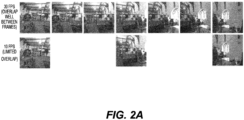
- FIG. 2A shows image sequences captured by a camera sensor operating at two different image frequencies, 30 frames per second (fps) and 10 fps. At 30 fps, there is a significant overlap between consecutive frames. In contrast, the images captured at 10 fps exhibits a noticeable reduction in the overlap between frames. Higher frame rates can ensure a smoother and more detailed representation of the scene, contributing to increased accuracy for the SLAM device.
- FIG. 2B shows a graph depicting the relationship between frame rate and accuracy of a SLAM device, in accordance with embodiments of the disclosure.
- the data depicted in FIG. 2B corresponding to the usage scenario illustrated in FIG. 2A , reveals a robust consistency in the translation error of the SLAM device.
- the SLAM device consistently maintains a translation error within a specified standard across a broad range of frame rates.
- both accuracy and power efficiency are crucial considerations for the SLAM device. While reducing the frame rate can contribute to decreased power consumption, it may also result in reduced accuracy. For general operative conditions, maintaining a normal or standard frame rate is advisable to ensure good accuracy. However, in certain usage scenarios involving, e.g., relatively slower motion or scenes with rich textures, adopting a lower frame rate can effectively reduce power consumption without compromising accuracy.
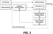
- FIG. 3 shows a block diagram of an exemplary adaptation apparatus 340 for performing frame rate adaptation in a SLAM device, in accordance with one embodiment of the disclosure.
- the SLAM device includes an Inertial Measurement Unit (IMU) sensor 310, a camera sensor 320, and a SLAM processor 330.
- the IMU sensor 310 measures accelerations and angular velocities using three-axis accelerometer and three-axis gyroscope, for example, to estimate the position and orientation of the SLAM device.
- the camera sensor 320 captures an image sequence of the surrounding environment, using either a single camera or multiple cameras.
- the SLAM processor 330 acquires data sensed by the IMU sensor 310 and the camera sensor 320, and processes the acquired data to generate a SLAM output.
- the SLAM output can include a detailed map of the environment and information about the current estimated position and orientation of the SLAM device within that map.
- the adaptation apparatus 340 can be integrated within the SLAM device, or arranged outside of the SLAM device.
- the adaptation apparatus 340 includes an operative condition determining module 342, a target frame rate deciding module 344, and a frame rate controlling module 346.
- the operative condition determining module 342 acquires the data processed inside the SLAM processor 330, and evaluates the operation state or condition of the SLAM device, based on the acquired data.
- the target frame rate deciding module 344 decides a target frame rate for the SLAM device.
- the frame rate controlling module 346 can be coupled between the camera sensor 320 and the SLAM processor 330. Based on the target frame rate received from the target frame rate deciding module 344, the frame rate controlling module 346 regulates the frame rate of the image sequence transmitted from the camera sensor 320 to the SLAM processor 330.
- the target frame rate can be set at a value lower than the standard frame rate used during normal operations.
- FIG. 4A shows exemplary operative conditions of the SLAM device, in accordance with embodiments of the disclosure.
- the operative conditions can involve the visual quality of the image sequence captured by the camera sensor. This can include aspects such as the richness of texture in the image sequence, the level of auto exposure (AE) in the image sequence, the amount of motion blur in the image sequence, the level of noise in the image sequence, resolution of the image sequence, and a frames-per-second of the image sequence, etc.
- AE level of auto exposure
- the operative conditions can be with respect to the utilization scenario of the SLAM device. This can include one or more factors such as the scale of the room where the SLAM device is used, the intensity of movement by the user wearing the SLAM device, the degree of frame drops in the SLAM device, the degree of camera mis-sync of the camera sensor, the number of other moving objects in the room, and the intensity of movement exhibited by these moving objects, etc.
- the operative conditions can be associated with the camera configuration of the camera sensor. This can include one of more of the number of cameras included in the camera sensor, locations of the cameras, fields-of-view of the cameras, and the degree of overlap between the cameras, etc.
- FIGs. 4B, 4C, and 4D show three exemplary operative conditions of the SLAM device, i.e., with numerous moving objects (represented by the rolling footballs in the scene), poor texture richness (absence of texture on the floor), and significant variation in the AE level.
- the target frame rate deciding module 344 can determine to use a higher target frame rate. For example, adopting the standard frame rate (e.g., 30 fps) used during normal operations can ensure the accuracy of the SLAM device under these specific operative conditions.
- FIG. 5 shows a graph depicting the relationship between frame rate and accuracy of a SLAM device under three different operative conditions, (1) rich texture, (2) poor texture, and (3) poor texture combined with fast motion, as tested with the SLAMCORE platform.
- a standard frame rate of 30 fps is not necessary for each of these operative conditions.
- a low-power mode operating at 15 fps can be sufficient to meet the accuracy requirements, e.g., 5cm, 3 degrees.
- FIG. 6 shows a flow chart of an exemplary procedure 600 for performing frame rate adaptation in a SLAM device, in accordance with embodiments of the disclosure.
- step S610 processed data within the SLAM processor is acquired.
- step S620 the target frame rate of the SLAM device is determined based on the acquired data.
- FIG. 3 shows that the processed data within the SLAM processor is directly used as the acquired data, one skilled in the art can recognize that an analysis of the data acquired from the SLAM processor can be performed for the determination of the target frame rate.
- step S630 a target frame rate for the SLAM device is decided based on the determined operative condition.
- step S640 frame rate adaptation is performed based on the decided target frame rate. Specifically, the frame rate of the image sequence transmitted from the camera sensor 320 to the SLAM processor 330 can be regulated to be the target frame rate.
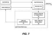
- FIG. 7 shows a block diagram of an exemplary adaptation apparatus 740 for performing frame rate adaptation in a SLAM device, in accordance with another embodiment of the disclosure.
- the adaptation apparatus 740 includes an operative condition determining module 742, a target frame rate deciding module 744, and a frame rate controlling module 746.
- the functions of the operative condition determining module 742 and the target frame rate deciding module 744 are identical to those of the corresponding components of the adaptation apparatus 340 in FIG. 3 .
- frame rate adaptation can be implemented by directly altering the sensing rate of the camera sensor.
- the frame rate controlling module 746 receives the target frame rate from the target frame rate deciding module 744, and executes adaptation by regulating the sensing rate of the camera sensor 720 to match the target frame rate.
- FIG. 3 and FIG. 7 might also be combined, i.e. a frame rate controlling module might regulate the frame rate of the image sequence transmitted from the camera sensor to the SLAM processor and alter the sensing rate of the camera sensor.
- both embodiments depicted in FIGs. 3 and 7 use the processed data within the SLAM processor to determine the operative condition of the SLAM device, additionally or alternatively, this determination can be based on data acquired from other sources, such as data sensed by one or more sensors of the SLAM device.
- FIG. 8 shows a block diagram of an exemplary adaptation apparatus 840 for performing frame rate adaptation in a SLAM device, in accordance with one embodiment of the disclosure.
- the adaptation apparatus 840 includes a data analyzing module 841, an operative condition determining module 842, a target frame rate deciding module 844, and a frame rate controlling module 846.
- the data analyzing module 841 receives and analyzes data from the IMU sensor 810. Based on the data analysis performed by the data analyzing module 841, the operative condition determining module 842 determines the operative condition of the SLAM device.
- the functions of the target frame rate deciding module 844 and the frame rate controlling module 846 can be identical to those of the corresponding components of the adaptation apparatus 340 shown in FIG. 3 .
- frame rate adaptation can be achieved by directly adjusting the sensing rate of the camera sensor, rather than regulating the frame rate of the image sequence transmitted from the camera sensor to the SLAM processor. Also, as indicated above, regulating the frame rate of the image sequence transmitted from the camera sensor to the SLAM processor might be performed together with directly adjusting the sensing rate of the camera sensor.
- FIG. 9 shows a block diagram of an exemplary adaptation apparatus 940 for performing frame rate adaptation in a SLAM device, in accordance with one embodiment of the disclosure.
- the adaptation apparatus 940 includes a data analyzing module 941, an operative condition determining module 942, a target frame rate deciding module 944, and a frame rate controlling module 946.
- the data analyzing module 941 receives and analyzes data sensed by the camera sensor 920. Based on the data analysis performed by the data analyzing module 941, the operative condition determining module 942 determines the operative condition of the SLAM device.
- the functions of the target frame rate deciding module 944 and the frame rate controlling module 946 are same as those of the corresponding components of the adaptation apparatus 340 shown in FIG. 3 .
- the embodiments of FIG. 8 and FIG. 9 might also be combined, i.e. a data analyzing module receives and analyzes data sensed by a camera sensor and from an IMU sensor. Further, in the embodiments of FIG. 8 and FIG.
- the operative condition determining module 942 might determine the operative condition of the SLAM device based on the data analysis performed by the data analyzing module and based on data processed inside the SLAM processor like in the embodiment of FIG. 3 .
- frame rate adaptation can be achieved by directly adjusting the sensing rate of the camera sensor, rather than regulating the frame rate of the image sequence transmitted from the camera sensor to the SLAM processor. Also, regulating the frame rate of the image sequence transmitted from the camera sensor to the SLAM processor might be performed together with directly adjusting the sensing rate of the camera sensor.
- FIG. 10 shows a schematic block diagram of an exemplary apparatus 1000 that can incorporate the techniques disclosed herein.
- the apparatus 1000 can be configured to perform various functions in accordance with one or more embodiments or examples described herein.
- the apparatus 1000 can provide means for implementation of mechanisms, techniques, processes, functions, components, systems described herein.
- the apparatus 1000 can be used to implement functions of AI-based feature extractors, non-AI-based feature extractors, key-point detectors, key-point descriptors, KRF modules, AI-based feature extraction modules, add-on frameworks, modules in a V-SLAM system in various embodiments and examples described herein.
- the apparatus 1000 can include a general-purpose processor or specially designed circuits to implement various functions, components, or processes described herein in various embodiments.
- the apparatus 1000 can include processing circuitry 1010, and a memory 1020.
- the processing circuitry 1010 can include circuitry configured to perform the functions and processes described herein in combination with software or without software.
- the processing circuitry 1010 can be a central processing unit (CPU), a graphic process unit (GPU), an accelerated processing unit (APU), a digital signal processor (DSP), an application specific integrated circuit (ASIC), programmable logic devices (PLDs), field programmable gate arrays (FPGAs), digitally enhanced circuits, or comparable device or a combination thereof.
- CPU central processing unit
- GPU graphic process unit
- APU accelerated processing unit
- DSP digital signal processor
- ASIC application specific integrated circuit
- PLDs programmable logic devices
- FPGAs field programmable gate arrays
- the processing circuitry 1010 can be a central processing unit (CPU) or an accelerated processing unit (APU) configured to execute program instructions to perform various functions and processes described herein.
- the memory 1020 can be configured to store program instructions.
- the processing circuitry 1010 when executing the program instructions, can perform the functions and processes.
- the memory 1020 can further store other programs or data, such as operating systems, application programs, and the like.
- the memory 1020 can include non-transitory storage media, such as a read only memory (ROM), a random access memory (RAM), a flash memory, a solid state memory, a hard disk drive, an optical disk drive, and the like.
- the apparatus 1000 can optionally include other components, such as input and output devices, additional or signal processing circuitry, and the like. Accordingly, the apparatus 1000 may be capable of performing other additional functions, such as executing application programs, image processing algorithms, input or output data, or the like.
- the processes and functions described herein can be implemented as a computer program which, when executed by one or more processors, can cause the one or more processors to perform the respective processes and functions.
- the computer program may be stored or distributed on a suitable medium, such as an optical storage medium or a solid-state medium supplied together with, or as part of, other hardware.
- the computer program may also be distributed in other forms, such as via the Internet or other wired or wireless telecommunication systems.
- the computer program can be obtained and loaded into an apparatus, including obtaining the computer program through physical medium or distributed system, including, for example, from a server connected to the Internet.
- the computer program may be accessible from a computer-readable medium providing program instructions for use by or in connection with a computer or any instruction execution system.
- the computer readable medium may include any apparatus that stores, communicates, propagates, or transports the computer program for use by or in connection with an instruction execution system, apparatus, or device.
- the computer-readable medium can be magnetic, optical, electronic, electromagnetic, infrared, or semiconductor system (or apparatus or device) or a propagation medium.
- the computer-readable medium may include a computer-readable non-transitory storage medium such as a semiconductor or solid-state memory, magnetic tape, a removable computer diskette, a random-access memory (RAM), a read-only memory (ROM), a magnetic disk and an optical disk, and the like.
- the computer-readable non-transitory storage medium can include all types of computer readable medium, including magnetic storage medium, optical storage medium, flash medium, and solid state storage medium.
Landscapes
- Engineering & Computer Science (AREA)
- Physics & Mathematics (AREA)
- General Physics & Mathematics (AREA)
- Theoretical Computer Science (AREA)
- Computer Vision & Pattern Recognition (AREA)
- Multimedia (AREA)
- General Engineering & Computer Science (AREA)
- Optics & Photonics (AREA)
- Quality & Reliability (AREA)
- Human Computer Interaction (AREA)
- Signal Processing (AREA)
- Studio Devices (AREA)
- User Interface Of Digital Computer (AREA)
Abstract
Description
- The present application claims priority to
U.S. Provisional Application No. 63/484,206, filed on February 10, 2023 - The present disclosure relates generally to extended reality (XR). In particular, the disclosure relates to enhanced simultaneous localization and mapping (SLAM) used in XR tracking.
- Simultaneous localization and mapping (SLAM) is a fundamental element in the operation of an extended reality (XR) apparatus, such as augmented reality (AR) and virtual reality (VR) systems. By continuously analyzing data from various sensors (for example, cameras, gyroscopes, accelerometers, etc.), a SLAM device enables the XR apparatus to determine its precise location in the physical environment in real time. As the XR apparatus moves, the SLAM device can dynamically establish and update a comprehensive map of the surrounding environment. By this way, the SLAM device can track the movements of the XR apparatus and the user wearing the XR apparatus within the mapped environment.
- It is desirable to improve the performance of SLAM devices to help achieve more attractive XR experiences.
- A method, an apparatus, and a non-transitory computer readable medium according to the invention are defined in the independent claims. The dependent claims define preferred embodiments thereof. Aspects of the disclosure provide a method for performing frame rate adaptation in a simultaneous localization and mapping (SLAM) device. The SLAM device includes a SLAM processor. The method includes: acquiring data from the SLAM device; determining, based on the acquired data, an operative condition of the SLAM device; deciding, based on the determined operative condition, a target frame rate for the SLAM device; and controlling, based on the decided target frame rate, a frame rate of an image sequence inputted into the SLAM processor.
- Aspects of the disclosure provide an apparatus for performing frame rate adaptation in a SLAM device. The SLAM device includes a SLAM processor. The apparatus includes processing circuitry configured to: acquire data from the SLAM device; determine, based on the acquired data, an operative condition with respect to the SLAM device; decide, based on the determined operative condition, a target frame rate for the SLAM device; and control, based on the decided target frame rate, a frame rate of an image sequence inputted into the SLAM processor.
- Aspects of the disclosure also provide a non-transitory computer-readable medium storing instructions. The instructions, when executed by a processor, can cause the processor to perform the above method for performing frame rate adaptation in a SLAM device.
- Note that this summary section does not specify every embodiment and/or incrementally novel aspect of the present disclosure or claimed invention. Instead, the summary only provides a preliminary discussion of different embodiments and corresponding points of novelty. For additional details and/or possible perspectives of the invention and embodiments, the reader is directed to the Detailed Description section and corresponding figures of the present disclosure as further discussed below.
- Various embodiments of this disclosure that are proposed as examples will be described in detail with reference to the following figures, wherein like numerals reference like elements, and wherein:
-
FIG. 1 illustrates typical requirements for a simultaneous localization and mapping (SLAM) device deployed in an extended reality (XR) apparatus, in accordance with embodiments of the disclosure; -
FIG. 2A shows exemplary image sequences captured by a camera sensor at two different image frequencies (30 frames-per-second (fps) and 10 fps), in accordance with embodiments of the disclosure; -
FIG. 2B shows a graph depicting the relationship between frame rate and accuracy of a SLAM device, in accordance with embodiments of the disclosure; -
FIG. 3 shows a block diagram of an exemplary adaptation apparatus for performing frame rate adaptation in a SLAM device, in accordance with one embodiment of the disclosure; -
FIGs. 4A ,4B, 4C, and 4D illustrate different operative conditions of a SLAM device, in accordance with embodiments of the disclosure; -
FIG. 5 shows a graph depicting the relationship between frame rate and accuracy of a SLAM device under three different operative conditions (rich texture, poor texture, and poor texture combined with fast motion), in accordance with embodiments of the disclosure; -
FIG. 6 shows a flow chart of an exemplary procedure for performing frame rate adaptation in a SLAM device, in accordance with one embodiment of the disclosure; -
FIG. 7 shows a block diagram of an exemplary adaptation apparatus for performing frame rate adaptation in a SLAM device, in accordance with one embodiment of the disclosure; -
FIG. 8 shows a block diagram of an exemplary adaptation apparatus for performing frame rate adaptation in a SLAM device, in accordance with one embodiment of the disclosure; -
FIG. 9 shows a block diagram of an exemplary adaptation apparatus for performing frame rate adaptation in a SLAM device, in accordance with one embodiment of the disclosure; and -
FIG. 10 shows a schematic block diagram of an exemplary apparatus that can incorporate the techniques disclosed herein. - The following disclosure provides different embodiments, or examples, for implementing various features of the provided subject matter. Specific examples of components and arrangements are described below to simplify the present disclosure. These are, of course, merely examples and are not intended to be limiting.
- For example, the order of discussion of the steps as described herein has been presented for the sake of clarity. In general, these steps can be performed in any suitable order. Additionally, although each of the different features, techniques, and configurations, etc., herein may be discussed in different places of this disclosure, it is intended that each of the concepts can be executed independently of each other or in combination with each other. Accordingly, the present disclosure can be embodied and viewed in many different ways.
- Furthermore, as used herein, the words "a," "an," and the like generally carry a meaning of "one or more," unless stated otherwise.
- To enhance the user experience with an extended reality (XR) apparatus, certain key requirements need to be met. Swift and precise tracking is essential to suppress potential motion sickness during XR interactions. Therefore, one crucial consideration is to maintain low-latency and high-accuracy tracking across essential components, including the user's head, hands, controllers, and eye movements.
-
FIG. 1 illustrates the typical latency parameter requirements for a simultaneous localization and mapping (SLAM) device deployed in an XR apparatus, in accordance with embodiments of the disclosure. Specifically, the Motion-To-Realtime-Pose (MTRP) latency represents the duration for the SLAM device to detect a movement and accordingly update the virtual representation, including position and orientation. Furthermore, the Motion-To-Photon (MTP) latency represents the time from when the user makes a movement to the moment they perceive the corresponding change in the displayed content, i.e., the time taken for a movement to be translated into the final photons reaching the user's eyes. - Ideally, the MTRP latency should be less than 2 ms. Additionally, maintaining an MTP latency of less than 15 ms is desirable to ensure that the XR environment responds promptly to user actions. Moreover, for XR systems equipped with pose-prediction capabilities, the MTP latency can be further reduced to 0 ms, indicating virtually instantaneous translation of user movements into the XR environment.
- When users engage in prolonged XR experiences, minimizing power consumption becomes important. This is particularly crucial for fanless XR systems, aiming for a sustained playtime of no less than three hours, for example. High energy efficiency not only enhances the overall user experience, but also facilitates uninterrupted XR engagement, allowing users to immerse themselves into XR content for extended durations without the inconvenience of frequent recharging.
- Additionally, achieving outstanding display quality is important to alleviate the screen-door visual effect, thereby ensuring a seamless and immersive XR environment. Meeting these requirements can optimize performance and foster user comfort within XR systems, but requires to maintain a balance among competing factors.
-
FIG. 2A shows image sequences captured by a camera sensor operating at two different image frequencies, 30 frames per second (fps) and 10 fps. At 30 fps, there is a significant overlap between consecutive frames. In contrast, the images captured at 10 fps exhibits a noticeable reduction in the overlap between frames. Higher frame rates can ensure a smoother and more detailed representation of the scene, contributing to increased accuracy for the SLAM device. - However, when circumstances permit, a lower frame rate introduces a trade-off between accuracy and resource efficiency.
FIG. 2B shows a graph depicting the relationship between frame rate and accuracy of a SLAM device, in accordance with embodiments of the disclosure. The data depicted inFIG. 2B , corresponding to the usage scenario illustrated inFIG. 2A , reveals a robust consistency in the translation error of the SLAM device. As can be seen fromFIG. 2B , the SLAM device consistently maintains a translation error within a specified standard across a broad range of frame rates. - In summary, both accuracy and power efficiency are crucial considerations for the SLAM device. While reducing the frame rate can contribute to decreased power consumption, it may also result in reduced accuracy. For general operative conditions, maintaining a normal or standard frame rate is advisable to ensure good accuracy. However, in certain usage scenarios involving, e.g., relatively slower motion or scenes with rich textures, adopting a lower frame rate can effectively reduce power consumption without compromising accuracy.
-
FIG. 3 shows a block diagram of an exemplary adaptation apparatus 340 for performing frame rate adaptation in a SLAM device, in accordance with one embodiment of the disclosure. The SLAM device includes an Inertial Measurement Unit (IMU) sensor 310, acamera sensor 320, and aSLAM processor 330. The IMU sensor 310 measures accelerations and angular velocities using three-axis accelerometer and three-axis gyroscope, for example, to estimate the position and orientation of the SLAM device. Simultaneously, thecamera sensor 320 captures an image sequence of the surrounding environment, using either a single camera or multiple cameras. TheSLAM processor 330 acquires data sensed by the IMU sensor 310 and thecamera sensor 320, and processes the acquired data to generate a SLAM output. Typically, the SLAM output can include a detailed map of the environment and information about the current estimated position and orientation of the SLAM device within that map. - The adaptation apparatus 340 can be integrated within the SLAM device, or arranged outside of the SLAM device. The adaptation apparatus 340 includes an operative
condition determining module 342, a target framerate deciding module 344, and a framerate controlling module 346. - The operative
condition determining module 342 acquires the data processed inside theSLAM processor 330, and evaluates the operation state or condition of the SLAM device, based on the acquired data. - Based on the operative condition received from the operative
condition determining module 342, the target framerate deciding module 344 decides a target frame rate for the SLAM device. - The frame
rate controlling module 346 can be coupled between thecamera sensor 320 and theSLAM processor 330. Based on the target frame rate received from the target framerate deciding module 344, the framerate controlling module 346 regulates the frame rate of the image sequence transmitted from thecamera sensor 320 to theSLAM processor 330. - For example, under certain operative conditions, the target frame rate can be set at a value lower than the standard frame rate used during normal operations. By means of this dynamic frame rate adaptation mechanism, it is possible to achieve a balance between maintaining accuracy and optimizing the energy efficiency of the SLAM device.
-
FIG. 4A shows exemplary operative conditions of the SLAM device, in accordance with embodiments of the disclosure. - For example, the operative conditions can involve the visual quality of the image sequence captured by the camera sensor. This can include aspects such as the richness of texture in the image sequence, the level of auto exposure (AE) in the image sequence, the amount of motion blur in the image sequence, the level of noise in the image sequence, resolution of the image sequence, and a frames-per-second of the image sequence, etc.
- As another example, the operative conditions can be with respect to the utilization scenario of the SLAM device. This can include one or more factors such as the scale of the room where the SLAM device is used, the intensity of movement by the user wearing the SLAM device, the degree of frame drops in the SLAM device, the degree of camera mis-sync of the camera sensor, the number of other moving objects in the room, and the intensity of movement exhibited by these moving objects, etc.
- Additionally, the operative conditions can be associated with the camera configuration of the camera sensor. This can include one of more of the number of cameras included in the camera sensor, locations of the cameras, fields-of-view of the cameras, and the degree of overlap between the cameras, etc.
- Note that the operative conditions enumerated in
FIG. 4A are illustrative and not exhaustive. It is possible to use other specific operative conditions without deviating from the scope of the disclosure. -
FIGs. 4B, 4C, and 4D show three exemplary operative conditions of the SLAM device, i.e., with numerous moving objects (represented by the rolling footballs in the scene), poor texture richness (absence of texture on the floor), and significant variation in the AE level. In scenarios where lots of moving object exist in the surrounding environment, the scene exhibits poor texture richness, or there is high AE variation, the target framerate deciding module 344 can determine to use a higher target frame rate. For example, adopting the standard frame rate (e.g., 30 fps) used during normal operations can ensure the accuracy of the SLAM device under these specific operative conditions. -
FIG. 5 shows a graph depicting the relationship between frame rate and accuracy of a SLAM device under three different operative conditions, (1) rich texture, (2) poor texture, and (3) poor texture combined with fast motion, as tested with the SLAMCORE platform. As can be seen fromFIG. 5 , a standard frame rate of 30 fps is not necessary for each of these operative conditions. For the usage scenario (3), a low-power mode operating at 15 fps can be sufficient to meet the accuracy requirements, e.g., 5cm, 3 degrees. For the usage scenarios (1) and (2), it is also possible to adaptively reduce the frame rate to 10 fps or even 5 fps while preserving accuracy. -
FIG. 6 shows a flow chart of anexemplary procedure 600 for performing frame rate adaptation in a SLAM device, in accordance with embodiments of the disclosure. In step S610, processed data within the SLAM processor is acquired. Subsequently, in step S620, the target frame rate of the SLAM device is determined based on the acquired data. AlthoughFIG. 3 shows that the processed data within the SLAM processor is directly used as the acquired data, one skilled in the art can recognize that an analysis of the data acquired from the SLAM processor can be performed for the determination of the target frame rate. - In step S630, a target frame rate for the SLAM device is decided based on the determined operative condition. In step S640, frame rate adaptation is performed based on the decided target frame rate. Specifically, the frame rate of the image sequence transmitted from the
camera sensor 320 to theSLAM processor 330 can be regulated to be the target frame rate. - Note that the deployment of
FIGs. 3 and6 is merely illustrative and not restrictive.FIG. 7 shows a block diagram of an exemplary adaptation apparatus 740 for performing frame rate adaptation in a SLAM device, in accordance with another embodiment of the disclosure. In the configuration shown inFIG. 7 , the adaptation apparatus 740 includes an operativecondition determining module 742, a target frame rate deciding module 744, and a framerate controlling module 746. - The functions of the operative
condition determining module 742 and the target frame rate deciding module 744 are identical to those of the corresponding components of the adaptation apparatus 340 inFIG. 3 . Instead of regulating the frame rate of the image sequence transmitted from the camera sensor to the SLAM processor, frame rate adaptation can be implemented by directly altering the sensing rate of the camera sensor. Specifically, the framerate controlling module 746 receives the target frame rate from the target frame rate deciding module 744, and executes adaptation by regulating the sensing rate of thecamera sensor 720 to match the target frame rate. The embodiments ofFIG. 3 andFIG. 7 might also be combined, i.e. a frame rate controlling module might regulate the frame rate of the image sequence transmitted from the camera sensor to the SLAM processor and alter the sensing rate of the camera sensor. - While both embodiments depicted in
FIGs. 3 and7 use the processed data within the SLAM processor to determine the operative condition of the SLAM device, additionally or alternatively, this determination can be based on data acquired from other sources, such as data sensed by one or more sensors of the SLAM device. -
FIG. 8 shows a block diagram of an exemplary adaptation apparatus 840 for performing frame rate adaptation in a SLAM device, in accordance with one embodiment of the disclosure. The adaptation apparatus 840 includes adata analyzing module 841, an operative condition determining module 842, a target framerate deciding module 844, and a framerate controlling module 846. - The
data analyzing module 841 receives and analyzes data from the IMU sensor 810. Based on the data analysis performed by thedata analyzing module 841, the operative condition determining module 842 determines the operative condition of the SLAM device. The functions of the target framerate deciding module 844 and the framerate controlling module 846 can be identical to those of the corresponding components of the adaptation apparatus 340 shown inFIG. 3 . - As described above, in the configuration illustrated in
FIG. 8 , frame rate adaptation can be achieved by directly adjusting the sensing rate of the camera sensor, rather than regulating the frame rate of the image sequence transmitted from the camera sensor to the SLAM processor. Also, as indicated above, regulating the frame rate of the image sequence transmitted from the camera sensor to the SLAM processor might be performed together with directly adjusting the sensing rate of the camera sensor. - The determination of the operative condition can also be based on data acquired from the camera sensor.
FIG. 9 shows a block diagram of an exemplary adaptation apparatus 940 for performing frame rate adaptation in a SLAM device, in accordance with one embodiment of the disclosure. The adaptation apparatus 940 includes adata analyzing module 941, an operative condition determining module 942, a target framerate deciding module 944, and a framerate controlling module 946. - The
data analyzing module 941 receives and analyzes data sensed by thecamera sensor 920. Based on the data analysis performed by thedata analyzing module 941, the operative condition determining module 942 determines the operative condition of the SLAM device. The functions of the target framerate deciding module 944 and the framerate controlling module 946 are same as those of the corresponding components of the adaptation apparatus 340 shown inFIG. 3 . The embodiments ofFIG. 8 andFIG. 9 might also be combined, i.e. a data analyzing module receives and analyzes data sensed by a camera sensor and from an IMU sensor. Further, in the embodiments ofFIG. 8 andFIG. 9 as well as in the combined embodiment, the operative condition determining module 942 might determine the operative condition of the SLAM device based on the data analysis performed by the data analyzing module and based on data processed inside the SLAM processor like in the embodiment ofFIG. 3 . - Similarly, in the configuration illustrated in
FIG. 9 , frame rate adaptation can be achieved by directly adjusting the sensing rate of the camera sensor, rather than regulating the frame rate of the image sequence transmitted from the camera sensor to the SLAM processor. Also, regulating the frame rate of the image sequence transmitted from the camera sensor to the SLAM processor might be performed together with directly adjusting the sensing rate of the camera sensor. -
FIG. 10 shows a schematic block diagram of an exemplary apparatus 1000 that can incorporate the techniques disclosed herein. The apparatus 1000 can be configured to perform various functions in accordance with one or more embodiments or examples described herein. Thus, the apparatus 1000 can provide means for implementation of mechanisms, techniques, processes, functions, components, systems described herein. - For example, the apparatus 1000 can be used to implement functions of AI-based feature extractors, non-AI-based feature extractors, key-point detectors, key-point descriptors, KRF modules, AI-based feature extraction modules, add-on frameworks, modules in a V-SLAM system in various embodiments and examples described herein. The apparatus 1000 can include a general-purpose processor or specially designed circuits to implement various functions, components, or processes described herein in various embodiments. The apparatus 1000 can include
processing circuitry 1010, and amemory 1020. - In various examples, the
processing circuitry 1010 can include circuitry configured to perform the functions and processes described herein in combination with software or without software. In various examples, theprocessing circuitry 1010 can be a central processing unit (CPU), a graphic process unit (GPU), an accelerated processing unit (APU), a digital signal processor (DSP), an application specific integrated circuit (ASIC), programmable logic devices (PLDs), field programmable gate arrays (FPGAs), digitally enhanced circuits, or comparable device or a combination thereof. - In some other examples, the
processing circuitry 1010 can be a central processing unit (CPU) or an accelerated processing unit (APU) configured to execute program instructions to perform various functions and processes described herein. Accordingly, thememory 1020 can be configured to store program instructions. Theprocessing circuitry 1010, when executing the program instructions, can perform the functions and processes. Thememory 1020 can further store other programs or data, such as operating systems, application programs, and the like. Thememory 1020 can include non-transitory storage media, such as a read only memory (ROM), a random access memory (RAM), a flash memory, a solid state memory, a hard disk drive, an optical disk drive, and the like. - The apparatus 1000 can optionally include other components, such as input and output devices, additional or signal processing circuitry, and the like. Accordingly, the apparatus 1000 may be capable of performing other additional functions, such as executing application programs, image processing algorithms, input or output data, or the like.
- The processes and functions described herein can be implemented as a computer program which, when executed by one or more processors, can cause the one or more processors to perform the respective processes and functions. The computer program may be stored or distributed on a suitable medium, such as an optical storage medium or a solid-state medium supplied together with, or as part of, other hardware. The computer program may also be distributed in other forms, such as via the Internet or other wired or wireless telecommunication systems. For example, the computer program can be obtained and loaded into an apparatus, including obtaining the computer program through physical medium or distributed system, including, for example, from a server connected to the Internet.
- The computer program may be accessible from a computer-readable medium providing program instructions for use by or in connection with a computer or any instruction execution system. The computer readable medium may include any apparatus that stores, communicates, propagates, or transports the computer program for use by or in connection with an instruction execution system, apparatus, or device. The computer-readable medium can be magnetic, optical, electronic, electromagnetic, infrared, or semiconductor system (or apparatus or device) or a propagation medium. The computer-readable medium may include a computer-readable non-transitory storage medium such as a semiconductor or solid-state memory, magnetic tape, a removable computer diskette, a random-access memory (RAM), a read-only memory (ROM), a magnetic disk and an optical disk, and the like. The computer-readable non-transitory storage medium can include all types of computer readable medium, including magnetic storage medium, optical storage medium, flash medium, and solid state storage medium.
- While aspects of the present disclosure have been described in conjunction with the specific embodiments thereof that are proposed as examples, alternatives, modifications, and variations to the examples may be made. Accordingly, embodiments as set forth herein are intended to be illustrative and not limiting. There are changes that may be made without departing from the scope of the claims set forth below.
Claims (15)
- A method for performing frame rate adaptation in a simultaneous localization and mapping, in the following also referred to as SLAM, device, the SLAM device including a SLAM processor, the method comprising:acquiring data from the SLAM device (S610);determining, based on the acquired data, an operative condition of the SLAM device (S620);deciding, based on the determined operative condition, a target frame rate for the SLAM device (S630); andcontrolling, based on the decided target frame rate, a frame rate of an image sequence inputted into the SLAM processor (S640).
- The method of claim 1, wherein the acquiring step further comprises acquiring, as the acquired data, data processed inside the SLAM processor; and/orwherein the SLAM device further includes an inertial measurement unit, in the following also referred to as IMU, sensor, and the acquiring step further comprises:receiving data outputted from the IMU sensor to the SLAM processor, andanalyzing the received data to generate the acquired data; and/orwherein the SLAM device further includes a camera sensor, and the acquiring step further comprises:receiving data outputted from the camera sensor to the SLAM processor, andanalyzing the received data to generate the acquired data.
- The method of claim 1 or 2, wherein the SLAM device further includes a/the camera sensor, the determining step further comprises determining, as the operative condition of the SLAM device, a visual quality of an image sequence captured by the camera sensor, and the visual quality includes at least one of:richness of texture in the image sequence,a level of auto exposure in the image sequence,an amount of motion blur in the image sequence,a level of noise in the image sequence,resolution of the image sequence, anda frames-per-second of the image sequence.
- The method of any one of claims 1 to 3, wherein the SLAM device further includes a/the camera sensor, the determining step further comprises determining, as the operative condition of the SLAM device, a utilization scenario of the SLAM device, and the utilization scenario includes at least one of:a scale of a room where the SLAM device is used,an intensity of movement by a person wearing the SLAM device,a degree of frame drops in the SLAM device,a degree of camera mis-sync of the camera sensor,a number of moving objects in the room, andan intensity of movement by the moving objects.
- The method of any one of claims 1 to 4, wherein the SLAM device further includes a/the camera sensor, the determining step further comprises determining, as the operative condition of the SLAM device, a camera configuration of the camera sensor, and the camera configuration includes at least one of:a number of cameras included in the camera sensor,locations of the cameras,fields-of-view of the cameras, anda degree of overlap between the cameras.
- The method of any one of claims 1 to 5, wherein the deciding step further comprises:
upon the determined operative condition meeting a predefined criterion, setting the target frame rate lower than a predefined value. - The method of any one of claims 1 to 6, wherein the SLAM device further includes a/the camera sensor, and the controlling step further comprises:controlling a sensing rate of the camera sensor to the decided target frame rate; and/orregulating, to the decided target frame rate, a frame rate of an image sequence transmitted from the camera sensor to the SLAM processor.
- An apparatus (1000) for performing frame rate adaptation in a simultaneous localization and mapping, in the following also referred to as SLAM, device, the SLAM device including a SLAM processor, the apparatus comprising processing circuitry (1010) configured to:acquire data from the SLAM device;determine, based on the acquired data, an operative condition with respect to the SLAM device;decide, based on the determined operative condition, a target frame rate for the SLAM device; andcontrol, based on the decided target frame rate, a frame rate of an image sequence inputted into the SLAM processor.
- The apparatus (1000) of claim 8, wherein the processing circuitry (1010) is further configured to acquire, as the acquired data, data processed inside the SLAM processor; and/orwherein the SLAM device further includes an inertial measurement unit, in the following also referred to as IMU, sensor, and the processing circuitry (1010) is further configured to:receive data outputted from the IMU sensor to the SLAM processor, andanalyze the received data to generate the acquired data; and/orwherein the SLAM device further includes a camera sensor, and the processing circuitry (1010) is further configured to:receive data outputted from the camera sensor to the SLAM processor, andanalyze the received data to generate the acquired data.
- The apparatus (1000) of claim 8 or 9, wherein the SLAM device further includes a/the camera sensor, the processing circuitry (1010) is further configured to determine a visual quality of an image sequence captured by the camera sensor as the operative condition of the SLAM device, and the visual quality includes at least one of:richness of texture in the image sequence,a level of auto exposure in the image sequence,an amount of motion blur in the image sequence,a level of noise in the image sequence,resolution of the image sequence, anda frames-per-second of the image sequence.
- The apparatus (1000) of any one of claims 8 to 10, wherein the SLAM device further includes a/the camera sensor, the processing circuitry (1010) is further configured to determine a utilization scenario of the SLAM device as the operative condition of the SLAM device, and the utilization scenario includes at least one of:a scale of a room where the SLAM device is used,an intensity of movement by a person wearing the SLAM device,a degree of frame drops in the SLAM device,a degree of camera mis-sync of the camera sensor,a number of moving objects in the room, andan intensity of movement by the moving objects.
- The apparatus (1000) of any one of claims 8 to 11, wherein the SLAM device further includes a/the camera sensor, the processing circuitry (1010) is further configured to determine a camera configuration of the camera sensor as the operative condition of the SLAM device, and the camera configuration includes at least one of:a number of cameras included in the camera sensor,locations of the cameras,fields-of-view of the cameras, anda degree of overlap between the cameras.
- The apparatus (1000) of any one of claims 8 to 12, wherein the processing circuitry (1010) is further configured to:
upon the determined operative condition meeting a predefined criterion, set the target frame rate lower than a predefined value. - The apparatus (1000) of any one of claims 8 to 13, wherein the SLAM device further includes a/the camera sensor, and the processing circuitry (1010) is further configured to:control a sensing rate of the camera sensor to the decided target frame rate; and/orregulating, to the decided target frame rate, a frame rate of an image sequence transmitted from the camera sensor to the SLAM processor.
- A non-transitory computer readable medium including computer readable instructions, which when executed by at least one processor, cause the at least one processor to perform a method for performing frame rate adaptation in a simultaneous localization and mapping, in the following also referred to as SLAM, device, the SLAM device including a SLAM processor, the method comprising the method steps as defined in any one of claims 1 to 7.
Applications Claiming Priority (2)
| Application Number | Priority Date | Filing Date | Title |
|---|---|---|---|
| US202363484206P | 2023-02-10 | 2023-02-10 | |
| US18/433,194 US20240273745A1 (en) | 2023-02-10 | 2024-02-05 | Adaptive frame rate for low power slam in xr |
Publications (1)
| Publication Number | Publication Date |
|---|---|
| EP4415374A1 true EP4415374A1 (en) | 2024-08-14 |
Family
ID=89854521
Family Applications (1)
| Application Number | Title | Priority Date | Filing Date |
|---|---|---|---|
| EP24156404.6A Pending EP4415374A1 (en) | 2023-02-10 | 2024-02-07 | Adaptive frame rate for low power slam in xr |
Country Status (3)
| Country | Link |
|---|---|
| US (1) | US20240273745A1 (en) |
| EP (1) | EP4415374A1 (en) |
| TW (1) | TWI895982B (en) |
Citations (2)
| Publication number | Priority date | Publication date | Assignee | Title |
|---|---|---|---|---|
| US10684469B2 (en) * | 2018-10-23 | 2020-06-16 | Dell Products L.P. | Detecting and mitigating motion sickness in augmented and virtual reality systems |
| WO2022201785A1 (en) * | 2021-03-22 | 2022-09-29 | ソニーグループ株式会社 | Information processing device and method, and program |
Family Cites Families (12)
| Publication number | Priority date | Publication date | Assignee | Title |
|---|---|---|---|---|
| KR102071575B1 (en) * | 2013-04-23 | 2020-01-30 | 삼성전자 주식회사 | Moving robot, user terminal apparatus, and control method thereof |
| US9759918B2 (en) * | 2014-05-01 | 2017-09-12 | Microsoft Technology Licensing, Llc | 3D mapping with flexible camera rig |
| CN105940674B (en) * | 2014-12-31 | 2018-07-27 | 深圳市大疆创新科技有限公司 | Systems and methods for adjusting the baseline of an imaging system having a microlens array |
| US11016302B2 (en) * | 2015-03-17 | 2021-05-25 | Raytrx, Llc | Wearable image manipulation and control system with high resolution micro-displays and dynamic opacity augmentation in augmented reality glasses |
| US10628950B2 (en) * | 2017-03-01 | 2020-04-21 | Microsoft Technology Licensing, Llc | Multi-spectrum illumination-and-sensor module for head tracking, gesture recognition and spatial mapping |
| GB2574418B (en) * | 2018-06-05 | 2022-08-31 | Dyson Technology Ltd | A mobile robot and method of controlling a mobile robot illumination system |
| JP7378431B2 (en) * | 2018-06-18 | 2023-11-13 | マジック リープ, インコーポレイテッド | Augmented reality display with frame modulation functionality |
| US12347192B2 (en) * | 2020-07-30 | 2025-07-01 | Samsung Electronics Co., Ltd. | Methods and systems for improving DVS features for computer vision applications |
| US11353711B1 (en) * | 2020-08-03 | 2022-06-07 | Raytrx, Llc | Wearable pupil-forming display apparatus |
| US11906736B1 (en) * | 2020-08-03 | 2024-02-20 | Raytrx, Llc | Wearable pupil-forming display apparatus |
| JP7596333B2 (en) * | 2022-06-30 | 2024-12-09 | キヤノン株式会社 | HEAD-MOUNTED DISPLAY DEVICE, IMAGE PROCESSING DEVICE, CONTROL METHOD FOR HEAD-MOUNTED DISPLAY DEVICE, AND PROGRAM |
| CN115525055B (en) * | 2022-09-28 | 2025-03-21 | 广州高新兴机器人有限公司 | Indoor robot autonomous exploration and mapping method, device and robot |
-
2024
- 2024-02-05 US US18/433,194 patent/US20240273745A1/en active Pending
- 2024-02-07 EP EP24156404.6A patent/EP4415374A1/en active Pending
- 2024-02-07 TW TW113105087A patent/TWI895982B/en active
Patent Citations (3)
| Publication number | Priority date | Publication date | Assignee | Title |
|---|---|---|---|---|
| US10684469B2 (en) * | 2018-10-23 | 2020-06-16 | Dell Products L.P. | Detecting and mitigating motion sickness in augmented and virtual reality systems |
| WO2022201785A1 (en) * | 2021-03-22 | 2022-09-29 | ソニーグループ株式会社 | Information processing device and method, and program |
| US20240169580A1 (en) * | 2021-03-22 | 2024-05-23 | Sony Group Corporation | Information processing device, information processing method, and program |
Non-Patent Citations (2)
| Title |
|---|
| SILVEIRA G ET AL: "An Efficient Direct Approach to Visual SLAM", IEEE TRANSACTIONS ON ROBOTICS, IEEE SERVICE CENTER, PISCATAWAY, NJ, US, vol. 24, no. 5, 1 October 2008 (2008-10-01), pages 969 - 979, XP011332771, ISSN: 1552-3098, DOI: 10.1109/TRO.2008.2004829 * |
| YINLONG ZHANG ET AL: "Robust orientation estimate via inertial guided visual sample consensus", PERSONAL AND UBIQUITOUS COMPUTING, SPRINGER VERLAG, LONDON, GB, vol. 22, no. 2, 1 April 2018 (2018-04-01), pages 259 - 274, XP058401676, ISSN: 1617-4909, DOI: 10.1007/S00779-017-1040-2 * |
Also Published As
| Publication number | Publication date |
|---|---|
| TWI895982B (en) | 2025-09-01 |
| TW202433244A (en) | 2024-08-16 |
| US20240273745A1 (en) | 2024-08-15 |
Similar Documents
| Publication | Publication Date | Title |
|---|---|---|
| JP7095030B2 (en) | Adjusting video rendering speed and processing 3D images of virtual reality content | |
| CN111627116B (en) | Image rendering control method and device and server | |
| US10529071B2 (en) | Facial skin mask generation for heart rate detection | |
| US9832451B2 (en) | Methods for reduced-bandwidth wireless 3D video transmission | |
| US10547779B2 (en) | Smart image sensor having integrated memory and processor | |
| CN105452935B (en) | Predictive tracking-based perception for head-mounted displays | |
| KR20210038669A (en) | Prediction and throttling adjustment based on application rendering performance | |
| US20190244369A1 (en) | Display device and method for image processing | |
| EP3535644A1 (en) | Streaming virtual reality video | |
| KR20160047488A (en) | Systems, devices and methods for tracking objects on a display | |
| US12284439B2 (en) | Systems and methods for dynamic stabilization adjustment | |
| JP6533761B2 (en) | INFORMATION PROCESSING APPARATUS, INFORMATION PROCESSING SYSTEM, AND INFORMATION PROCESSING METHOD | |
| US11726320B2 (en) | Information processing apparatus, information processing method, and program | |
| KR101434072B1 (en) | Stabilisation method and computer system | |
| US20240273745A1 (en) | Adaptive frame rate for low power slam in xr | |
| US12573139B2 (en) | Ordering data received from an augmented reality service to provide a virtual reality experience | |
| KR20160062665A (en) | Apparatus and method for analyzing motion | |
| US20240314428A1 (en) | Adaptive camera scheme for low power slam in xr | |
| CN118488324A (en) | Adaptive frame rate for low power SLAM in XR | |
| US12520038B1 (en) | Smart glasses device and response instruction generating method | |
| US20240265636A1 (en) | Temporal Blending of Depth Maps | |
| US20240348933A1 (en) | Adaptive exposure | |
| US20250173963A1 (en) | Screen recording method and apparatus of extended reality device, device, medium, and program | |
| CN120224024A (en) | Shooting control method and device | |
| CN120928627A (en) | Head-mounted display device |
Legal Events
| Date | Code | Title | Description |
|---|---|---|---|
| PUAI | Public reference made under article 153(3) epc to a published international application that has entered the european phase |
Free format text: ORIGINAL CODE: 0009012 |
|
| STAA | Information on the status of an ep patent application or granted ep patent |
Free format text: STATUS: THE APPLICATION HAS BEEN PUBLISHED |
|
| AK | Designated contracting states |
Kind code of ref document: A1 Designated state(s): AL AT BE BG CH CY CZ DE DK EE ES FI FR GB GR HR HU IE IS IT LI LT LU LV MC ME MK MT NL NO PL PT RO RS SE SI SK SM TR |
|
| STAA | Information on the status of an ep patent application or granted ep patent |
Free format text: STATUS: REQUEST FOR EXAMINATION WAS MADE |
|
| 17P | Request for examination filed |
Effective date: 20250206 |
|
| STAA | Information on the status of an ep patent application or granted ep patent |
Free format text: STATUS: EXAMINATION IS IN PROGRESS |
|
| 17Q | First examination report despatched |
Effective date: 20251223 |