EP4415345A1 - Communication apparatus, control method for communication apparatus, and storage medium - Google Patents
Communication apparatus, control method for communication apparatus, and storage medium Download PDFInfo
- Publication number
- EP4415345A1 EP4415345A1 EP24155222.3A EP24155222A EP4415345A1 EP 4415345 A1 EP4415345 A1 EP 4415345A1 EP 24155222 A EP24155222 A EP 24155222A EP 4415345 A1 EP4415345 A1 EP 4415345A1
- Authority
- EP
- European Patent Office
- Prior art keywords
- audio data
- wireless microphone
- audio
- external apparatus
- control unit
- Prior art date
- Legal status (The legal status is an assumption and is not a legal conclusion. Google has not performed a legal analysis and makes no representation as to the accuracy of the status listed.)
- Granted
Links
Images



Classifications
-
- G—PHYSICS
- G11—INFORMATION STORAGE
- G11B—INFORMATION STORAGE BASED ON RELATIVE MOVEMENT BETWEEN RECORD CARRIER AND TRANSDUCER
- G11B27/00—Editing; Indexing; Addressing; Timing or synchronising; Monitoring; Measuring tape travel
- G11B27/02—Editing, e.g. varying the order of information signals recorded on, or reproduced from, record carriers
- G11B27/031—Electronic editing of digitised analogue information signals, e.g. audio or video signals
-
- G—PHYSICS
- G11—INFORMATION STORAGE
- G11B—INFORMATION STORAGE BASED ON RELATIVE MOVEMENT BETWEEN RECORD CARRIER AND TRANSDUCER
- G11B20/00—Signal processing not specific to the method of recording or reproducing; Circuits therefor
- G11B20/10—Digital recording or reproducing
- G11B20/10527—Audio or video recording; Data buffering arrangements
-
- H—ELECTRICITY
- H04—ELECTRIC COMMUNICATION TECHNIQUE
- H04R—LOUDSPEAKERS, MICROPHONES, GRAMOPHONE PICK-UPS OR LIKE ACOUSTIC ELECTROMECHANICAL TRANSDUCERS; ELECTRIC HEARING AIDS; PUBLIC ADDRESS SYSTEMS
- H04R3/00—Circuits for transducers
-
- G—PHYSICS
- G06—COMPUTING OR CALCULATING; COUNTING
- G06F—ELECTRIC DIGITAL DATA PROCESSING
- G06F3/00—Input arrangements for transferring data to be processed into a form capable of being handled by the computer; Output arrangements for transferring data from processing unit to output unit, e.g. interface arrangements
- G06F3/16—Sound input; Sound output
- G06F3/165—Management of the audio stream, e.g. setting of volume, audio stream path
-
- G—PHYSICS
- G11—INFORMATION STORAGE
- G11B—INFORMATION STORAGE BASED ON RELATIVE MOVEMENT BETWEEN RECORD CARRIER AND TRANSDUCER
- G11B27/00—Editing; Indexing; Addressing; Timing or synchronising; Monitoring; Measuring tape travel
- G11B27/10—Indexing; Addressing; Timing or synchronising; Measuring tape travel
- G11B27/19—Indexing; Addressing; Timing or synchronising; Measuring tape travel by using information detectable on the record carrier
- G11B27/28—Indexing; Addressing; Timing or synchronising; Measuring tape travel by using information detectable on the record carrier by using information signals recorded by the same method as the main recording
- G11B27/32—Indexing; Addressing; Timing or synchronising; Measuring tape travel by using information detectable on the record carrier by using information signals recorded by the same method as the main recording on separate auxiliary tracks of the same or an auxiliary record carrier
- G11B27/322—Indexing; Addressing; Timing or synchronising; Measuring tape travel by using information detectable on the record carrier by using information signals recorded by the same method as the main recording on separate auxiliary tracks of the same or an auxiliary record carrier used signal is digitally coded
-
- H—ELECTRICITY
- H04—ELECTRIC COMMUNICATION TECHNIQUE
- H04N—PICTORIAL COMMUNICATION, e.g. TELEVISION
- H04N23/00—Cameras or camera modules comprising electronic image sensors; Control thereof
- H04N23/60—Control of cameras or camera modules
-
- H—ELECTRICITY
- H04—ELECTRIC COMMUNICATION TECHNIQUE
- H04N—PICTORIAL COMMUNICATION, e.g. TELEVISION
- H04N5/00—Details of television systems
- H04N5/76—Television signal recording
- H04N5/765—Interface circuits between an apparatus for recording and another apparatus
- H04N5/77—Interface circuits between an apparatus for recording and another apparatus between a recording apparatus and a television camera
- H04N5/772—Interface circuits between an apparatus for recording and another apparatus between a recording apparatus and a television camera the recording apparatus and the television camera being placed in the same enclosure
-
- H—ELECTRICITY
- H04—ELECTRIC COMMUNICATION TECHNIQUE
- H04R—LOUDSPEAKERS, MICROPHONES, GRAMOPHONE PICK-UPS OR LIKE ACOUSTIC ELECTROMECHANICAL TRANSDUCERS; ELECTRIC HEARING AIDS; PUBLIC ADDRESS SYSTEMS
- H04R1/00—Details of transducers, loudspeakers or microphones
- H04R1/08—Mouthpieces; Microphones; Attachments therefor
-
- G—PHYSICS
- G11—INFORMATION STORAGE
- G11B—INFORMATION STORAGE BASED ON RELATIVE MOVEMENT BETWEEN RECORD CARRIER AND TRANSDUCER
- G11B20/00—Signal processing not specific to the method of recording or reproducing; Circuits therefor
- G11B20/10—Digital recording or reproducing
- G11B2020/10851—Erasing data on the record carrier
Definitions
- the present invention relates to a communication apparatus, a control method for a communication apparatus, and a storage medium.
- a known technique stores transmitted or received audio data as recorded data in a storage medium for keeping a record when audio data is wireless transmitted and received.
- Japanese Patent No. 6108788 described above does not take into account how to handle the backup of audio data with a possibility of the communication partner being unable to receive it as expected.
- the present invention has been made in consideration of the aforementioned problems and realizes a technique enabling appropriate handling of audio data for backup.
- the present invention in its first aspect provides a communication apparatus as specified in claims 1 to 10.
- the present invention in its second aspect provides a communication apparatus as specified in claims 11 to 13.
- the present invention in its third aspect provides a method of controlling a communication apparatus as specified in claim 14.
- the present invention in its forth aspect provides a computer-readable storage medium as specified in claim 15.
- audio data for backup can be appropriately handled.
- a wireless microphone that can capture audio of a user's speech is used as an example of a communication apparatus.
- the present embodiment is not limited to a wireless microphone and is applicable to other devices that can capture audio. Examples of such devices may include, for example, a wireless earphone, a smartphone, a game console, a tablet terminal, and other information terminals.
- a digital camera that can record received audio data as well as video data is used as an example of an imaging device.
- the present embodiment is not limited to a digital camera and is applicable to other devices that can stored received audio data together with video data. Examples of such devices may include, for example, a smartphone, a game console, a tablet terminal, a personal computer, and the like.
- the imaging system according to the first embodiment includes a wireless communication camera 100, a receiver 300, and a wireless microphone 400, for example.
- ASIC application-specific integrated circuit
- PDA programmable logic array
- a programmable processor such as a central processing unit (CPU) or a microprocessing unit (MPU), executing software.
- CPU central processing unit
- MPU microprocessing unit
- these may be implemented by a combination of software and hardware.
- the wireless microphone 400 transmits audio data obtained by capturing audio of the surroundings to the receiver 300 via wireless communication.
- the audio data received by the receiver 300 is transmitted to the camera 100.
- the camera 100 receives the audio data transmitted from the wireless microphone 400 via the receiver 300.
- the wireless microphone 400 can also store captured audio data.
- a replaceable imaging lens 200 is used.
- the present embodiment is not particularly limited to using a replaceable imaging lens.
- the camera 100 may include a built-in imaging lens. Also, the camera 100 may include a part or all of the functional configuration of the receiver 300.
- the imaging lens 200 is installed at the front surface of the camera 100.
- the imaging lens 200 is replaceable, and the camera 100 and the imaging lens 200 are electrically connected via a mount contact group 103.
- the receiver 300 is installed at the upper surface of the camera 100.
- the receiver 300 is configured to be replaceable, and the camera 100 and the receiver 300 are electrically connected via an ACC shoe contact group 109.
- a camera control unit 101 includes one or more processors (for example, a CPU) for controlling the operations of the units of the camera 100 and also includes a built-in memory for storing various types of adjustment values, programs for executing various types of control, and the like.
- the built-in memory functions as a buffer memory for temporarily storing various types of data processed at each location.
- the camera control unit 101 controls the various types of operations of the camera 100 by executing a program stored in the built-in memory or a camera storage unit 107.
- An image sensor 102 converts light from an object incident via a lens 202 into an electrical signal, generates an image signal including a still image or video, and outputs this to the camera control unit 101.
- a shutter 104 for example, is a focal plane shutter disposed between the image sensor 102 and the lens 202 that operates as instructed by the camera control unit 101.
- the shutter 104 is constituted by a front curtain and a rear curtain. When the front curtain moves, the shutter opens and exposure of the image sensor 102 starts. When the rear curtain moves, the shutter closes and exposure of the image sensor 102 ends.
- a camera operation unit 105 includes an operation member operated by a user.
- the camera operation unit 105 detects a user operation via a button, switch, dial, connection device, or the like attached to the camera 100 and transmits a signal according to the operation instruction to the camera control unit 101.
- the camera operation unit 105 outputs, to the camera control unit 101, an instruction signal (SW1 signal) sent when the user performs a half press of the release button and an instruction signal (SW2 signal) sent when the user performs a full press to deeply press the release button.
- the camera operation unit 105 outputs, to the camera control unit 101, an instruction signal (REC signal) sent when the user operates the record button.
- a camera display unit 106 displays imaging information and captured images as instructed by the camera control unit 101.
- the camera control unit 101 controls the operations of the camera 100 on the basis of an output signal of the camera operation unit 105.
- the output signal of the camera operation unit 105 is the SW1 signal
- the image sensor 102 is driven and imaging is performed and focus information such as the defocus amount of each distance measuring point is output.
- the object is detected from the imaging result, photometry control (AE operation) to measure the brightness of the object is repeated together, and the shutter speed, f-number, and ISO sensitivity used when imaging are determined on the basis of the photometry result.
- the shutter speed, f-number, and ISO sensitivity used when imaging are collectively referred to as exposure control values.
- the determined exposure control values are displayed on the screen of the camera display unit 106.
- a diaphragm 203 is driven via a lens control unit 201, the sensitivity (ISO sensitivity) of the image sensor 102 is set, and the shutter 104 is controlled to emit light at the image sensor 102.
- the output signal of the camera operation unit 105 is the REC signal
- the sensitivity (ISO sensitivity) of the image sensor 102 and the frame rate is set, the image sensor 102 is driven and imaging is performed, and focus information such as the defocus amount of each distance measuring point is output.
- the object is detected from the imaging result and light is emitted at the image sensor 102 while photometry control (AE operation) to measure the brightness of the object is repeated.
- the lens control unit 201 described below drives the focus lens (not illustrated) for adjusting the focus in the imaging lens 200 and repeats autofocus as instructed by the camera control unit 101.
- the camera control unit 101 performs control to display the captured image on the camera display unit 106 according to the still image data or the video data obtained from the image sensor 102 and to write the still image data or the video data (including attached sound information) to the camera storage unit 107.
- a camera wireless communication unit 108 performs wireless communication between the camera 100 and an external apparatus.
- the camera wireless communication unit 108 transmits and receives image data, audio data, compressed image data, compressed audio data, and similar types of data, for example.
- the camera wireless communication unit 108 transmits and receives control signals relating to imaging such as imaging start and end commands and other information.
- the camera wireless communication unit 108 for example, is an infrared communication module, a Bluetooth (registered trademark) communication module, a wireless LAN communication module, a Wireless USB or similar wireless communication module, or the like.
- audio data from the wireless microphone 400 is received via the receiver 300.
- the camera wireless communication unit 108 may have the functional configuration of the receiver 300, and the camera 100 may perform wireless communication directly with the wireless microphone 400.
- a camera audio input unit 110 captures audio of the surroundings of the camera 100 via a built-in microphone, an external microphone connected via an audio input terminal, or the like, performs analog-to-digital conversion, and transmits this to the camera control unit 101.
- the camera control unit 101 executes, on the input digital audio data, audio-related processing such as level optimization processing, specific frequency reduction processing, audio detection processing, and the like and executes processing to combine the video data obtained by the image sensor 102 and the audio data obtained from the wireless microphone 400.
- the camera control unit 101 performs control to write the combined data to the camera storage unit 107 as video data with sound information.
- the microphone may be a monaural or a stereo microphone.
- the lens control unit 201 includes one or more processors (for example, a CPU) for controlling the operations of the units of the imaging lens 200.
- the lens 202 is constituted by a plurality of lenses and focuses the object image on the image sensor 102.
- the diaphragm 203 for adjusting the amount of light and the focus lens (not illustrated) for adjusting the focus are also provided in the lens 202.
- the lens control unit 201 adjusts the amount of light taken inside the camera 100 and the focus according to an instruction from the camera control unit 101 under control via the mount contact group 103 and transmits the distance information and the like of this time to the camera control unit 101.
- a receiver control unit 301 includes one or more processors (for example, a CPU) for controlling the operations of the units of the receiver 300.
- the receiver control unit 301 for example, executes a program stored in the built-in memory of the receiver control unit 301 to control the various types of operations of the receiver 300.
- the receiver control unit 301 can communicate with the camera control unit 101 via the ACC shoe contact group 109.
- the receiver control unit 301 can transmit and receive audio data and compressed audio data as well as setting instructions from the camera 100, camera information, receiver information, wireless microphone information, and the like.
- a receiver wireless communication unit 302 as with the camera wireless communication unit 108, performs wireless communication between the receiver 300 and an external apparatus.
- the receiver wireless communication unit 302 transmits and receives data such as audio data and compressed audio data with an external apparatus and transmits and receives control signals relating to imaging such as imaging start and end commands and other information, for example.
- the receiver wireless communication unit 302, for example, is an infrared communication module, a Bluetooth (registered trademark) communication module, a wireless LAN communication module, a Wireless USB or similar wireless communication module, or the like.
- a receiver operation unit 303 includes an operation member operated by the user and detects a user operation via a button, dial, or the like attached to the receiver 300 and transmits a signal according to the operation instruction to the receiver control unit 301.
- a receiver display unit 304 displays information such as the communication state and mute as instructed by the receiver control unit 301.
- a receiver audio input unit 305 captures audio of the surroundings of the receiver 300 via a built-in microphone or the like, performs analog-to-digital conversion, and transmits this to the receiver control unit 301.
- the microphone may be a monaural or a stereo microphone.
- a wireless microphone control unit 401 includes one or more processors (for example, a CPU) for controlling the operations of the units of the wireless microphone 400.
- the wireless microphone control unit 401 for example, executes a program stored in a wireless microphone storage unit 406 to control the various types of operations of the wireless microphone 400.
- the wireless microphone control unit 401 can perform wireless communication with the receiver control unit 301 via a wireless microphone wireless communication unit 402 and the receiver wireless communication unit 302.
- the wireless microphone control unit 401 can transmit and receive audio data and compressed audio data as well as setting instructions from the camera 100, camera information, receiver information, wireless microphone information, and the like.
- the wireless microphone wireless communication unit 402 can perform wireless communication with an external apparatus.
- the wireless microphone wireless communication unit 402 transmits and receives audio data and compressed audio data obtained by a wireless microphone audio input unit 405 described below and information such as the individual identification number of the wireless microphone 400, the battery, mute, and the like as instructed by the wireless microphone control unit 401.
- the wireless microphone wireless communication unit 402, for example, is an infrared communication module, a Bluetooth (registered trademark) communication module, a wireless LAN communication module, a Wireless USB or similar wireless communication module, or the like.
- a wireless microphone operation unit 403 includes an operation member operated by the user and detects a user operation via a button, dial, or the like attached to the wireless microphone 400 and transmits a signal according to the operation instruction to the wireless microphone control unit 401.
- a wireless microphone display unit 404 displays information such as the communication state, mute, and battery as instructed by the wireless microphone control unit 401. Also, the individual identification number of the wireless microphone 400 is displayed. The individual identification number may be a serial number or the like.
- the wireless microphone audio input unit 405 captures audio of the surroundings of the wireless microphone 400 via a built-in microphone, an external microphone connected via an audio input terminal, or the like, performs analog-to-digital conversion, and transmits this to the wireless microphone control unit 401. Also, the audio data obtained by capturing and analog-to-digital conversion is also simultaneously stored in the wireless microphone storage unit 406 as backup audio data.
- the microphone is a monaural microphone, for example.
- the configuration of the wireless microphone audio input unit 405 may be similar to that of the camera audio input unit 110 and the receiver audio input unit 305.
- the audio data captured by the wireless microphone 400 is transmitted to the receiver 300, and processing is executed to combine the audio data with the video data captured by the camera 100 to which the receiver 300 is connected.
- the data obtained via combining processing is stored in the camera storage unit 107 as video data with sound information.
- the audio data is stored in the wireless microphone storage unit 406 in the wireless microphone 400 as backup audio data.
- the backup audio data can be read out after the end of imaging and can be replaced with the audio data combined with the video data with sound information stored in the camera 100.
- the backup audio data stored in the wireless microphone 400 is an audio file, and audio data uses a large amount of data.
- the storage capacity of the wireless microphone storage unit 406 may run out. Accordingly, in a situation where imaging data cannot be checked for a long period of time, such as when video recording for a long period of time, it is necessary to appropriately control the deletion of required backup audio data.
- FIGS. 2A and 2B illustrate a series of operations for capturing video according to the present embodiment.
- FIG. 2A illustrates the processing of the wireless microphone 400
- FIG. 2B illustrates the processing of the receiver 300 and the camera 100.
- the operations of the wireless microphone 400 are implemented by the wireless microphone control unit 401 executing a program stored in the wireless microphone storage unit 406 unless otherwise described.
- the operations of the receiver 300 are implemented by the receiver control unit 301 executing a program stored in the built-in memory, for example, unless otherwise described.
- the operations of the camera 100 are implemented by the camera control unit 101 executing a program stored in the camera storage unit 107, for example, unless otherwise described. Note that the operations illustrated in FIGS. 2A and 2B are started when the wireless microphone 400 and the receiver 300 are in a wirelessly connected state.
- step S251 the camera control unit 101 starts video capture according to a user operation of the camera operation unit 105.
- step S252 the camera control unit 101 notifies the wireless microphone 400 that video capture has started via the receiver 300.
- step S201 the wireless microphone control unit 401 receives the video capture start notification from the camera 100. Then, in step S202, the wireless microphone control unit 401 starts capturing the audio of the surroundings with the wireless microphone audio input unit 405.
- step S203 the wireless microphone control unit 401 performs analog-to-digital conversion on the captured audio and generates audio data.
- the wireless microphone control unit 401 starts real-time transmission (in other words, transmission as audio is captured) of the audio data generated in step S203 to the receiver 300 via the wireless microphone wireless communication unit 402.
- the wireless microphone control unit 401 continues the real-time transmission of audio data until the video capture ends, for example.
- step S205 the wireless microphone control unit 401 starts the storage of the audio data (backup audio data) as a backup also in the wireless microphone storage unit 406, and the processing proceeds to the data tagging processing of step S206.
- step S253 the receiver control unit 301 receives the audio data from the wireless microphone 400 via the receiver wireless communication unit 302.
- step S254 the camera control unit 101 obtains the audio data from the receiver 300, executing processing to combine the obtained audio data and the captured video data, and generates video data with sound information.
- step S255 the camera control unit 101 starts the storage of the video data with sound information generated in step S254 in the camera storage unit 107, and then the processing proceeds to the data tagging of step S256.
- the data tagging processing in steps S206 and S256 will now be described in detail with reference to FIGS. 3A and 3B .
- FIG. 3A illustrates the processing of the wireless microphone 400
- FIG. 3B illustrates the processing of the receiver 300 and the camera 100.
- the processing of the wireless microphone 400, the receiver 300, and the camera 100 are executed by the wireless microphone control unit 401, the receiver control unit 301, and the camera control unit 101, respectively, unless otherwise described.
- step S301 the wireless microphone control unit 401 starts monitoring the state of the wireless communication with the camera 100 via the wireless microphone wireless communication unit 402. Specifically, the received signal strength indicator (RSSI) of the electromagnetic wave signals transmitted from the receiver 300 is monitored.
- RSSI received signal strength indicator
- a received signal strength indicator that is high (closer to 0 dBm) indicates a strong electromagnetic wave state.
- -30 dBm to -40 dBm indicates a stable wireless connection
- -60 dBm or less indicates the start of an unstable wireless connection
- -90 dBm or less indicates a poor wireless connection.
- the wireless microphone control unit 401 determines whether or not the received signal strength indicator being monitored is equal to or greater than a threshold.
- the received signal strength indicator threshold may be set to around -60 dBm.
- the processing proceeds to step S303.
- the wireless microphone control unit 401 can determine that the wireless communication with the receiver 300 is in a stable state and that the audio data being transmitted from the wireless microphone 400 to the receiver 300 has a high possibility of being received in a good state.
- the processing proceeds to step S304. In this case, the wireless microphone control unit 401 can determine that there is a high possibility of the audio data being transmitted from the wireless microphone 400 to the receiver 300 being choppy, unclear, or of bad quality.
- step S303 the audio data being transmitted has a high possibility of being received in a good state.
- the wireless microphone control unit 401 continues the storage of the audio data in the wireless microphone storage unit 406 as normal backup audio data. Then, the wireless microphone control unit 401 ends the processing without executing tag processing on the stored audio data. Thereafter, the wireless microphone control unit 401 returns the processing back to the caller.
- step S304 since there is a high possibility that the transmitted audio data is in a reduced quality state, the wireless microphone control unit 401 tags the audio data stored in the wireless microphone storage unit 406 as backup audio data for prohibition of automatic deletion.
- the wireless microphone control unit 401 changes the permission information of the file attributes of the audio data file and sets it to deletion prohibited.
- the tag for prohibition of automatic deletion is an example of information indicating the prohibition of deletion according to a predetermined rule (in other words, automatic deletion).
- the control method for not deleting stored audio data is not limited to this example, and another method may be used. The details of the data tagging processing relating to automatic deletion prohibition will be described below with reference to FIG. 4 .
- step S305 the wireless microphone control unit 401 transmits, to the receiver 300, a request for information tagging (poor audio notification tag) indicating the possibility of the audio data being transmitted having reduced quality. Thereafter, the wireless microphone control unit 401 ends the data tagging processing returns the processing back to the caller.
- information tagging poor audio notification tag
- step S351 the receiver control unit 301 determines whether or not a request for poor audio notification tagging has been received from the wireless microphone 400. In a case where the receiver control unit 301 determines that a request for poor audio notification tagging has been received, the processing proceeds to step S352. Otherwise, the data tagging processing ends, and the processing returns to the caller.
- step S352 the camera control unit 101 tags the video data with sound information stored in the camera storage unit 107 with a poor audio notification tag.
- the camera control unit 101 incorporates them as a video data with audio file.
- the tagging method is not limited to this example, and another method may be used.
- the video data with sound information is tagged with a poor audio notification tag. This makes it easy to distinguish video data with sound information with a high possibility of the quality of the audio data being in a reduced state when reproducing the audio data after capturing has ended and reduces the effort involved in checking the audio data using the camera 100.
- the camera control unit 101 ends the data tagging processing and returns the processing back to the caller.
- step S257 the camera control unit 101 determines whether or not to end the video capture. In a case where the camera control unit 101 determines not to end the video capture on the basis of an operation of the camera operation unit 105, for example, the processing returns to step S253, and video capture continues. In a case where the camera control unit 101 determines to end video capture, data storage to the camera storage unit 107 also ends, and the processing proceeds to step S258.
- step S258 the camera control unit 101 notifies the wireless microphone 400 of the end of video capture (via the receiver 300) and then ends the operations relating to video capture on the camera 100 side.
- step S207 the wireless microphone control unit 401 determines whether or not a video capture end notification has been received from the receiver 300. In a case where the wireless microphone control unit 401 determines that a video capture end notification has not been received, the processing returns to step S202. In other words, the wireless microphone control unit 401 continues the real-time transmission of the captured audio data to the camera side and continues monitoring whether the wireless situation is one that requires the backup audio data to be tagged with an automatic deletion prohibition tag. In a case where the wireless microphone control unit 401 determines that a video capture end notification has been received, the processing proceeds to step S208, and the operations (in other words, storage of the backup audio data from capture and data tagging processing) relating to recording on the wireless microphone 400 side end.
- the operations in other words, storage of the backup audio data from capture and data tagging processing
- step S401 the wireless microphone control unit 401 determines whether or not the storage capacity of the wireless microphone storage unit 406 will be insufficient during the video capture describe in FIG. 2A . In a case where the wireless microphone control unit 401 determines that the storage capacity is not insufficient, the processing proceeds to step S402. In a case where the wireless microphone control unit 401 determines that the storage capacity is insufficient, the processing proceeds to step S403.
- step S402 the wireless microphone control unit 401 determines whether or not to end audio data recording. In a case where the wireless microphone control unit 401 determines to continue recording, the processing returns to step S401. In a case where the wireless microphone control unit 401 determines to end recording, the automatic deletion prohibition processing ends.
- step S403 the wireless microphone storage unit 406, as instructed by the wireless microphone control unit 401, arranges the stored audio data in order of date and time stored from the oldest and, for example, extracts the audio data with the oldest date and time stored as a deletion candidate.
- step S404 the wireless microphone control unit 401 determines whether the deletion candidate audio data is tagged with an automatic deletion prohibition tag. In a case where the wireless microphone control unit 401 determines that the extracted deletion candidate audio data is tagged with an automatic deletion prohibition tag, the processing proceeds to step S405. In step S405, the wireless microphone control unit 401 excludes that audio data for processing that is tagged with an automatic deletion prohibition tag from being a deletion candidate. Thereafter, the processing returns to step S403, and the wireless microphone control unit 401 extracts the next deletion candidate.
- step S404 in a case where the wireless microphone control unit 401 determines that the deletion candidate audio data is not tagged with an automatic deletion prohibition tag, the processing proceeds to step S406.
- step S406 the wireless microphone control unit 401 deletes the extracted audio data from the wireless microphone storage unit 406. Thereafter, the processing returns to step S401, and the wireless microphone control unit 401 repeats the processing for deleting audio data until capacity is freed up in the wireless microphone storage unit 406.
- the wireless microphone 400 communicates wirelessly with the receiver 300 and transmits captured audio data and stores the captured audio data in the wireless microphone storage unit 406. At this time, to resolve the wireless microphone storage unit 406 having insufficient capacity, the wireless microphone 400 performs control to delete stored audio data according to a predetermined rule (for example, according to the amount of time elapsed since stored). In the present embodiment, also, in a case where the wireless communication state does not satisfy a predetermined condition (the received signal strength indicator is less than the threshold), control is performed to not delete the target backup audio data stored in the wireless microphone storage unit 406 according to the predetermined rule.
- a predetermined rule for example, according to the amount of time elapsed since stored.
- audio data can be provided to the camera 100 without automatically deleting audio data from the wireless microphone storage unit 406.
- the audio data for backup in the wireless microphone 400 can be appropriately handled.
- deletion prohibition tagging has been used.
- deletion of audio data by automatic deletion may be delayed.
- an order for not being automatically deleted may be set with tags added for deletion priority or importance.
- a threshold for the received signal strength indicator is used to determine the wireless communication state.
- the signal-to-noise ratio (SNR) is also taken into account. Note that in the present embodiment, the data tagging processing is different to that in the embodiment described above. However, the configuration of the wireless microphone 400, the receiver 300, and the camera 100 and the other processing are essentially the same. Thus, configurations and processing which are essentially the same are given the same reference number and the descriptions thereof are omitted. The differences will be focused on in the following description.
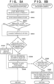
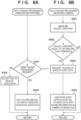
- FIG. 5A illustrates the processing of the wireless microphone 400
- FIG. 5B illustrates the processing of the receiver 300 and the camera 100. Note that the processing of the wireless microphone 400, the receiver 300, and the camera 100 are executed by the wireless microphone control unit 401, the receiver control unit 301, and the camera control unit 101, respectively, unless otherwise described.
- step S501 the wireless microphone control unit 401 starts monitoring the wireless communication state with the receiver 300, that is, the received signal strength indicator (RSSI) of the electromagnetic wave signal transmitted from the receiver 300, via the wireless microphone wireless communication unit 402.
- RSSI received signal strength indicator
- step S502 the wireless microphone control unit 401 starts monitoring the noise floor measurement value and calculates SNR.
- SNR means the difference between the received signal strength indicator and the noise floor.
- a SNR value of 25 dB or greater is recommended, for example.
- step S503 the wireless microphone control unit 401 determines whether or not the SNR is equal to or greater than the threshold. In a case where the wireless microphone control unit 401 determines that the SNR is equal to or greater than the threshold, the processing proceeds to step S505 without a change to the received signal strength indicator threshold. On the other hand, in a case where the wireless microphone control unit 401 determines that the SNR is less than the threshold, the effect of electromagnetic wave interference is determined to be great, and the processing proceeds to step S504. In step S504, due to the electromagnetic wave interference being great, the wireless microphone control unit 401 changes the received signal strength indicator threshold by increasing it to make the criterion for the received signal strength indicator stricter.
- the wireless microphone control unit 401 executes the processing of step S302 onward. Also as in the first embodiment described above, the camera control unit 101 executes the operations of step S351 onward.
- the wireless microphone control unit 401 takes into account not only the received signal strength indicator but also the SNR.
- the quality of the transmitted audio data can be estimated with a better accuracy.
- the automatic deletion of backup audio data with a high possibility of having poor audio quality can be appropriately prohibited.
- data tagging processing according to the third embodiment will be described with reference to FIGS. 6A and 6B .
- audio data received by the receiver 300 is transmitted unchanged to the wireless microphone 400, and a comparison of the audio data before transmission on the wireless microphone 400 side and the returned audio data is used to determine the wireless communication state.
- the data tagging processing is different to that in the embodiment described above.
- the configuration of the wireless microphone 400, the receiver 300, and the camera 100 and the other processing are essentially the same.
- configurations and processing which are essentially the same are given the same reference number and the descriptions thereof are omitted. The differences will be focused on in the following description.
- FIG. 6A illustrates the processing of the wireless microphone 400
- FIG. 6B illustrates the data tagging processing of the receiver 300 and the camera 100. Note that the processing of the wireless microphone 400, the receiver 300, and the camera 100 are executed by the wireless microphone control unit 401, the receiver control unit 301, and the camera control unit 101, respectively, unless otherwise described.
- step S651 the receiver control unit 301 transmits the audio data received in step S253 described above back to the wireless microphone 400 via the receiver wireless communication unit 302.
- step S601 the wireless microphone control unit 401 receives the audio data transmitted from the receiver 300 in step S651.
- step S602 the wireless microphone control unit 401 compares the audio data transmitted from the wireless microphone 400 to the receiver 300 in step S204 and the audio data received in step S601 and calculates the audio match rate.
- the wireless microphone control unit 401 may calculate the rate of delay or missing due to the wireless communication state as the audio match rate.
- step S603 the wireless microphone 400 determines whether the calculated audio match rate is equal to or greater than a threshold. In a case where the wireless microphone 400 determines that the audio match rate is equal to or greater than the threshold, the processing proceeds to step S604. In a case where the wireless microphone 400 determines that the audio match rate is less than the threshold, the processing proceeds to step S605.
- the wireless microphone 400 executes the processing of step S303 onward. Also as in the embodiments described above, the camera control unit 101 executes the processing of step S351 onward.
- the wireless microphone control unit 401 uses the match rate between the audio data returned from the receiver 300 side and the transmitted audio data to estimate the quality of the transmitted audio data. In this manner, the automatic deletion of backup audio data with a high possibility of having poor audio quality can be appropriately prohibited.
- the fourth embodiment is different in that the received signal strength indicator on the receiver 300 side is monitored.
- the data tagging processing is different to that in the embodiment described above.
- the configuration of the wireless microphone 400, the receiver 300, and the camera 100 and the other processing are essentially the same.
- configurations and processing which are essentially the same are given the same reference number and the descriptions thereof are omitted. The differences will be focused on in the following description.
- FIG. 7A illustrates the processing of the wireless microphone 400
- FIG. 7B illustrates the data tagging processing of the receiver 300 and the camera 100.
- step S751 the receiver control unit 301 starts monitoring the wireless communication state with the wireless microphone 400, that is, the received signal strength indicator (RSSI) of the electromagnetic waves transmitted from the wireless microphone 400.
- the camera control unit 101 may obtain the received signal strength indicator measured by the receiver 300.
- step S752 the receiver control unit 301 determines whether or not the received signal strength indicator being monitored is equal to or greater than a threshold. In a case where the receiver control unit 301 determines that the received signal strength indicator is equal to or greater than the threshold, the data tagging processing ends as is, and the processing returns to the caller with the processing proceeding to step S257 in FIG. 2B . In this case, it can be assumed that the wireless communication state is stable and the audio data received from the wireless microphone 400 has a high possibility of being in a good state. On the other hand, in a case where the receiver control unit 301 determines that the received signal strength indicator is less than the threshold, the processing proceeds to step S753. In this case, it can be assumed that the audio data received from the wireless microphone 400 has a high possibility of having reduced quality.
- step S753 since there is a high possibility that the audio data being received has reduced quality, the receiver control unit 301 sends a notification requesting the backup audio data stored in the wireless microphone storage unit 406 to be tagged for automatic deletion prohibition.
- step S352 simultaneously, the camera control unit 101 tags the video data with sound information stored in the camera storage unit 107 with a poor audio tag. Thereafter, the camera control unit 101 ends the data tagging processing, and the processing proceeds to step S257 in FIG. 2B .
- step S701 the wireless microphone control unit 401 determines whether or not a backup data tagging request has been received from the receiver 300. In a case where the wireless microphone control unit 401 determines that a tagging request has not been received, the processing of step S303 described above is executed. On the other hand, in a case where the wireless microphone control unit 401 determines that a tagging request has been received, the processing of step S304 described above is executed.
- the received signal strength indicator on the receiver 300 side is monitored and, depending on the received signal strength indicator, an automatic deletion prohibition tagging request (information indicating automatic deletion prohibition) for the backup audio data is transmitted. In this manner, the automatic deletion of backup audio data with a high possibility of having reduced quality can be appropriately prohibited.
- an automatic deletion prohibition tagging request for the backup audio data is transmitted.
- the present embodiment is not limited to transmitting an automatic deletion prohibition tagging request, and information (information indicating a high possibility of the audio data having reduced quality) indicating that the wireless communication state does not satisfy a predetermined condition may be notified. In this manner, the wireless microphone 400 can perform control so that audio data is not automatically deleted.
- data tagging processing according to the fifth embodiment will be described with reference to FIGS. 8A and 8B .
- monitoring of the received signal strength indicator is used to determine the wireless communication state.
- the fifth embodiment is different in that the packet loss rate on the receiver 300 and the camera 100 side is used as a criterion.
- the configuration of the wireless microphone 400, the receiver 300, and the camera 100 and the other processing are essentially the same.
- configurations and processing which are essentially the same are given the same reference number and the descriptions thereof are omitted. The differences will be focused on in the following description.
- FIG. 8A illustrates the processing of the wireless microphone 400
- FIG. 8B illustrates the data tagging processing of the receiver 300 and the camera 100.
- step S851 the receiver control unit 301 measures the packet loss rate of the wireless communication with the wireless microphone 400.
- the wireless microphone 400 transmits the audio data transmitted in real time in small segmented packets, and all of the packets are collected and reconfigured on the receiver 300, which is the receiving side.
- packet loss tends to occur and due to the communication time increasing by an amount equivalent to the time needed to retransmit and receive the missing packets. This makes the communication delayed and choppy, and the quality of the audio data is reduced.
- the method for measuring packet loss rate used can be a known method.
- step S852 the receiver control unit 301 determines whether or not the packet loss rate is equal to or greater than a threshold. In a case where the receiver control unit 301 determines that the packet loss rate is equal to or greater than the threshold, the processing proceeds to step S853, and in step S853, the receiver control unit 301 sends a notification of a tagging request for the backup audio data to the wireless microphone side. Also, the receiver control unit 301 executes the processing of step S352 described above and ends the present processing.
- the receiver control unit 301 determines that the state of the audio data transmitted from the wireless microphone 400 is good and ends the data tagging processing without performing data tagging. Thereafter, the receiver control unit 301 returns the processing back to the caller.
- the wireless microphone 400 executes the processing of steps S700, S303, and S304 and returns the processing back to the caller.
- a tagging request for the backup audio data is transmitted. In this manner, even when the packet loss rate is a criterion, backup audio data with a high possibility of having reduced audio quality can be selected and prohibited from automatic deletion.
- Embodiment(s) of the present invention can also be realized by a computer of a system or apparatus that reads out and executes computer executable instructions (e.g., one or more programs) recorded on a storage medium (which may also be referred to more fully as a 'non-transitory computer-readable storage medium') to perform the functions of one or more of the above-described embodiment(s) and/or that includes one or more circuits (e.g., application specific integrated circuit (ASIC)) for performing the functions of one or more of the above-described embodiment(s), and by a method performed by the computer of the system or apparatus by, for example, reading out and executing the computer executable instructions from the storage medium to perform the functions of one or more of the above-described embodiment(s) and/or controlling the one or more circuits to perform the functions of one or more of the above-described embodiment(s).
- computer executable instructions e.g., one or more programs
- a storage medium which may also be referred to more fully as
- the computer may comprise one or more processors (e.g., central processing unit (CPU), micro processing unit (MPU)) and may include a network of separate computers or separate processors to read out and execute the computer executable instructions.
- the computer executable instructions may be provided to the computer, for example, from a network or the storage medium.
- the storage medium may include, for example, one or more of a hard disk, a random-access memory (RAM), a read only memory (ROM), a storage of distributed computing systems, an optical disk (such as a compact disc (CD), digital versatile disc (DVD), or Blu-ray Disc (BD) TM ), a flash memory device, a memory card, and the like.
- the apparatus stores the captured audio data and control deletion of the store audio data according to a predetermined rule.
- the apparatus performs control so that the stored audio data is not deleted according to the predetermined rule.
Landscapes
- Engineering & Computer Science (AREA)
- Signal Processing (AREA)
- Multimedia (AREA)
- Physics & Mathematics (AREA)
- Acoustics & Sound (AREA)
- Theoretical Computer Science (AREA)
- Audiology, Speech & Language Pathology (AREA)
- General Health & Medical Sciences (AREA)
- Human Computer Interaction (AREA)
- General Engineering & Computer Science (AREA)
- General Physics & Mathematics (AREA)
- Health & Medical Sciences (AREA)
- Studio Devices (AREA)
- Telephone Function (AREA)
Abstract
Description
- The present invention relates to a communication apparatus, a control method for a communication apparatus, and a storage medium.
- A known technique stores transmitted or received audio data as recorded data in a storage medium for keeping a record when audio data is wireless transmitted and received.
- With such a technique, when recorded data is accumulated, the remaining storage space of the storage medium decreases, making it necessary to delete data stored on the storage medium. In the technique proposed in
Japanese Patent No. 6108788 - However, when wireless communication is actually performed, audio data transmitted by one apparatus may not be received by the communication partner, or the quality of the received audio data may be reduced.
Japanese Patent No. 6108788 - The present invention has been made in consideration of the aforementioned problems and realizes a technique enabling appropriate handling of audio data for backup.
- The present invention in its first aspect provides a communication apparatus as specified in claims 1 to 10.
- The present invention in its second aspect provides a communication apparatus as specified in claims 11 to 13.
- The present invention in its third aspect provides a method of controlling a communication apparatus as specified in claim 14.
- The present invention in its forth aspect provides a computer-readable storage medium as specified in claim 15.
- According to the present invention, audio data for backup can be appropriately handled.
- Further features of the present invention will become apparent from the following description of exemplary embodiments (with reference to the attached drawings).
-
-
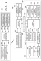
FIG. 1 is a block diagram illustrating an example of the configuration of an imaging system according to a first embodiment. -
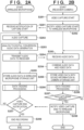
FIGS. 2A and 2B are flowcharts illustrating a series of operations of video capture according to the first embodiment. -
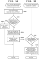
FIGS. 3A and 3B are flowcharts for describing a series of operations of tagging processing for audio data during video capture operation according to the first embodiment. -
FIG. 4 is a flowchart illustrating operations of automatic deletion prohibition performed by a wireless microphone storage unit according to the first embodiment. -
FIGS. 5A and 5B are flowcharts for describing a series of operations of tagging processing for audio data during video capture operation according to a second embodiment. -
FIGS. 6A and 6B are flowcharts for describing a series of operations of tagging processing for audio data during video capture operation according to a third embodiment. -
FIGS. 7A and 7B are flowcharts for describing a series of operations of tagging processing for audio data during video capture operation according to a fourth embodiment. -
FIGS. 8A and 8B are flowcharts for describing tagging processing for audio data during video capture operation according to a fifth embodiment. - Hereinafter, embodiments will be described in detail with reference to the attached drawings. Note, the following embodiments are not intended to limit the scope of the claimed invention. Multiple features are described in the embodiments, but limitation is not made to an invention that requires all such features, and multiple such features may be combined as appropriate. Furthermore, in the attached drawings, the same reference numerals are given to the same or similar configurations, and redundant description thereof is omitted.
- In the example described below, a wireless microphone that can capture audio of a user's speech is used as an example of a communication apparatus. However, the present embodiment is not limited to a wireless microphone and is applicable to other devices that can capture audio. Examples of such devices may include, for example, a wireless earphone, a smartphone, a game console, a tablet terminal, and other information terminals. Also, in the example described below, a digital camera that can record received audio data as well as video data is used as an example of an imaging device. However, the present embodiment is not limited to a digital camera and is applicable to other devices that can stored received audio data together with video data. Examples of such devices may include, for example, a smartphone, a game console, a tablet terminal, a personal computer, and the like.
- An example of the functional configuration of an imaging system according to the first embodiment will now be described with reference to
FIG. 1 . The imaging system according to the first embodiment includes awireless communication camera 100, areceiver 300, and awireless microphone 400, for example. Note that one or more functional blocks illustrated inFIG. 1 may be implemented by hardware, such as an application-specific integrated circuit (ASIC) or a programmable logic array (PLA), or implemented by a programmable processor, such as a central processing unit (CPU) or a microprocessing unit (MPU), executing software. Also, these may be implemented by a combination of software and hardware. - The
wireless microphone 400 according to the present embodiment transmits audio data obtained by capturing audio of the surroundings to thereceiver 300 via wireless communication. The audio data received by thereceiver 300 is transmitted to thecamera 100. In other words, thecamera 100 receives the audio data transmitted from thewireless microphone 400 via thereceiver 300. Note that, as described below, thewireless microphone 400 can also store captured audio data. Note that in the example illustrated inFIG. 1 , areplaceable imaging lens 200 is used. However, the present embodiment is not particularly limited to using a replaceable imaging lens. Thecamera 100 may include a built-in imaging lens. Also, thecamera 100 may include a part or all of the functional configuration of thereceiver 300. - As illustrated in
FIG. 1 , theimaging lens 200 is installed at the front surface of thecamera 100. Theimaging lens 200 is replaceable, and thecamera 100 and theimaging lens 200 are electrically connected via amount contact group 103. Thereceiver 300 is installed at the upper surface of thecamera 100. Thereceiver 300 is configured to be replaceable, and thecamera 100 and thereceiver 300 are electrically connected via an ACCshoe contact group 109. - First, an example of the configuration of the
camera 100 will be described. Acamera control unit 101 includes one or more processors (for example, a CPU) for controlling the operations of the units of thecamera 100 and also includes a built-in memory for storing various types of adjustment values, programs for executing various types of control, and the like. The built-in memory functions as a buffer memory for temporarily storing various types of data processed at each location. Thecamera control unit 101 controls the various types of operations of thecamera 100 by executing a program stored in the built-in memory or acamera storage unit 107. - An
image sensor 102 converts light from an object incident via alens 202 into an electrical signal, generates an image signal including a still image or video, and outputs this to thecamera control unit 101. Ashutter 104, for example, is a focal plane shutter disposed between theimage sensor 102 and thelens 202 that operates as instructed by thecamera control unit 101. Theshutter 104 is constituted by a front curtain and a rear curtain. When the front curtain moves, the shutter opens and exposure of theimage sensor 102 starts. When the rear curtain moves, the shutter closes and exposure of theimage sensor 102 ends. - A
camera operation unit 105 includes an operation member operated by a user. Thecamera operation unit 105 detects a user operation via a button, switch, dial, connection device, or the like attached to thecamera 100 and transmits a signal according to the operation instruction to thecamera control unit 101. In the case of capturing a still image, thecamera operation unit 105 outputs, to thecamera control unit 101, an instruction signal (SW1 signal) sent when the user performs a half press of the release button and an instruction signal (SW2 signal) sent when the user performs a full press to deeply press the release button. In the case of capturing a video, thecamera operation unit 105 outputs, to thecamera control unit 101, an instruction signal (REC signal) sent when the user operates the record button. - A
camera display unit 106 displays imaging information and captured images as instructed by thecamera control unit 101. Thecamera control unit 101 controls the operations of thecamera 100 on the basis of an output signal of thecamera operation unit 105. In a case where the output signal of thecamera operation unit 105 is the SW1 signal, theimage sensor 102 is driven and imaging is performed and focus information such as the defocus amount of each distance measuring point is output. Also, the object is detected from the imaging result, photometry control (AE operation) to measure the brightness of the object is repeated together, and the shutter speed, f-number, and ISO sensitivity used when imaging are determined on the basis of the photometry result. Here, the shutter speed, f-number, and ISO sensitivity used when imaging are collectively referred to as exposure control values. The determined exposure control values are displayed on the screen of thecamera display unit 106. In a case where the output signal of thecamera operation unit 105 is the SW2 signal, adiaphragm 203 is driven via alens control unit 201, the sensitivity (ISO sensitivity) of theimage sensor 102 is set, and theshutter 104 is controlled to emit light at theimage sensor 102. In a case where the output signal of thecamera operation unit 105 is the REC signal, the sensitivity (ISO sensitivity) of theimage sensor 102 and the frame rate is set, theimage sensor 102 is driven and imaging is performed, and focus information such as the defocus amount of each distance measuring point is output. Also, the object is detected from the imaging result and light is emitted at theimage sensor 102 while photometry control (AE operation) to measure the brightness of the object is repeated. Thelens control unit 201 described below drives the focus lens (not illustrated) for adjusting the focus in theimaging lens 200 and repeats autofocus as instructed by thecamera control unit 101. Thecamera control unit 101 performs control to display the captured image on thecamera display unit 106 according to the still image data or the video data obtained from theimage sensor 102 and to write the still image data or the video data (including attached sound information) to thecamera storage unit 107. - A camera
wireless communication unit 108 performs wireless communication between thecamera 100 and an external apparatus. The camerawireless communication unit 108, for example, transmits and receives image data, audio data, compressed image data, compressed audio data, and similar types of data, for example. Also, the camerawireless communication unit 108 transmits and receives control signals relating to imaging such as imaging start and end commands and other information. The camerawireless communication unit 108, for example, is an infrared communication module, a Bluetooth (registered trademark) communication module, a wireless LAN communication module, a Wireless USB or similar wireless communication module, or the like. Also, in the example configuration of the present embodiment described herein, audio data from thewireless microphone 400 is received via thereceiver 300. However, the camerawireless communication unit 108 may have the functional configuration of thereceiver 300, and thecamera 100 may perform wireless communication directly with thewireless microphone 400. - A camera
audio input unit 110 captures audio of the surroundings of thecamera 100 via a built-in microphone, an external microphone connected via an audio input terminal, or the like, performs analog-to-digital conversion, and transmits this to thecamera control unit 101. Thecamera control unit 101 executes, on the input digital audio data, audio-related processing such as level optimization processing, specific frequency reduction processing, audio detection processing, and the like and executes processing to combine the video data obtained by theimage sensor 102 and the audio data obtained from thewireless microphone 400. Thecamera control unit 101 performs control to write the combined data to thecamera storage unit 107 as video data with sound information. Note that the microphone may be a monaural or a stereo microphone. - Next, an example of the configuration of the
imaging lens 200 will be described. Thelens control unit 201 includes one or more processors (for example, a CPU) for controlling the operations of the units of theimaging lens 200. Thelens 202 is constituted by a plurality of lenses and focuses the object image on theimage sensor 102. Thediaphragm 203 for adjusting the amount of light and the focus lens (not illustrated) for adjusting the focus are also provided in thelens 202. Thelens control unit 201 adjusts the amount of light taken inside thecamera 100 and the focus according to an instruction from thecamera control unit 101 under control via themount contact group 103 and transmits the distance information and the like of this time to thecamera control unit 101. - An example of the configuration of the
receiver 300 will also now be described. Areceiver control unit 301 includes one or more processors (for example, a CPU) for controlling the operations of the units of thereceiver 300. Thereceiver control unit 301, for example, executes a program stored in the built-in memory of thereceiver control unit 301 to control the various types of operations of thereceiver 300. Thereceiver control unit 301 can communicate with thecamera control unit 101 via the ACCshoe contact group 109. Thereceiver control unit 301 can transmit and receive audio data and compressed audio data as well as setting instructions from thecamera 100, camera information, receiver information, wireless microphone information, and the like. - A receiver
wireless communication unit 302, as with the camerawireless communication unit 108, performs wireless communication between thereceiver 300 and an external apparatus. The receiverwireless communication unit 302 transmits and receives data such as audio data and compressed audio data with an external apparatus and transmits and receives control signals relating to imaging such as imaging start and end commands and other information, for example. The receiverwireless communication unit 302, for example, is an infrared communication module, a Bluetooth (registered trademark) communication module, a wireless LAN communication module, a Wireless USB or similar wireless communication module, or the like. - A
receiver operation unit 303 includes an operation member operated by the user and detects a user operation via a button, dial, or the like attached to thereceiver 300 and transmits a signal according to the operation instruction to thereceiver control unit 301. Areceiver display unit 304 displays information such as the communication state and mute as instructed by thereceiver control unit 301. - A receiver
audio input unit 305, as with the cameraaudio input unit 110, captures audio of the surroundings of thereceiver 300 via a built-in microphone or the like, performs analog-to-digital conversion, and transmits this to thereceiver control unit 301. Note that the microphone may be a monaural or a stereo microphone. - Next, an example of the configuration of the
wireless microphone 400 will be described. A wirelessmicrophone control unit 401 includes one or more processors (for example, a CPU) for controlling the operations of the units of thewireless microphone 400. The wirelessmicrophone control unit 401, for example, executes a program stored in a wirelessmicrophone storage unit 406 to control the various types of operations of thewireless microphone 400. The wirelessmicrophone control unit 401 can perform wireless communication with thereceiver control unit 301 via a wireless microphonewireless communication unit 402 and the receiverwireless communication unit 302. The wirelessmicrophone control unit 401 can transmit and receive audio data and compressed audio data as well as setting instructions from thecamera 100, camera information, receiver information, wireless microphone information, and the like. - The wireless microphone
wireless communication unit 402, as with the camerawireless communication unit 108 and the receiverwireless communication unit 302, can perform wireless communication with an external apparatus. The wireless microphonewireless communication unit 402 transmits and receives audio data and compressed audio data obtained by a wireless microphoneaudio input unit 405 described below and information such as the individual identification number of thewireless microphone 400, the battery, mute, and the like as instructed by the wirelessmicrophone control unit 401. The wireless microphonewireless communication unit 402, for example, is an infrared communication module, a Bluetooth (registered trademark) communication module, a wireless LAN communication module, a Wireless USB or similar wireless communication module, or the like. - A wireless
microphone operation unit 403 includes an operation member operated by the user and detects a user operation via a button, dial, or the like attached to thewireless microphone 400 and transmits a signal according to the operation instruction to the wirelessmicrophone control unit 401. - A wireless
microphone display unit 404 displays information such as the communication state, mute, and battery as instructed by the wirelessmicrophone control unit 401. Also, the individual identification number of thewireless microphone 400 is displayed. The individual identification number may be a serial number or the like. - The wireless microphone
audio input unit 405 captures audio of the surroundings of thewireless microphone 400 via a built-in microphone, an external microphone connected via an audio input terminal, or the like, performs analog-to-digital conversion, and transmits this to the wirelessmicrophone control unit 401. Also, the audio data obtained by capturing and analog-to-digital conversion is also simultaneously stored in the wirelessmicrophone storage unit 406 as backup audio data. The microphone is a monaural microphone, for example. The configuration of the wireless microphoneaudio input unit 405 may be similar to that of the cameraaudio input unit 110 and the receiveraudio input unit 305. - In capturing a video using the
wireless microphone 400 as described below, the audio data captured by thewireless microphone 400 is transmitted to thereceiver 300, and processing is executed to combine the audio data with the video data captured by thecamera 100 to which thereceiver 300 is connected. The data obtained via combining processing is stored in thecamera storage unit 107 as video data with sound information. Also, in thewireless microphone 400, the audio data is stored in the wirelessmicrophone storage unit 406 in thewireless microphone 400 as backup audio data. The backup audio data can be read out after the end of imaging and can be replaced with the audio data combined with the video data with sound information stored in thecamera 100. - The backup audio data stored in the
wireless microphone 400 is an audio file, and audio data uses a large amount of data. Thus, the storage capacity of the wirelessmicrophone storage unit 406 may run out. Accordingly, in a situation where imaging data cannot be checked for a long period of time, such as when video recording for a long period of time, it is necessary to appropriately control the deletion of required backup audio data. - A series of operations for capturing video using the
wireless microphone 400, thereceiver 300, and thecamera 100 according to the present embodiment will be described below with reference toFIGS. 2 to 4 . -
FIGS. 2A and 2B illustrate a series of operations for capturing video according to the present embodiment.FIG. 2A illustrates the processing of thewireless microphone 400, andFIG. 2B illustrates the processing of thereceiver 300 and thecamera 100. The operations of thewireless microphone 400 are implemented by the wirelessmicrophone control unit 401 executing a program stored in the wirelessmicrophone storage unit 406 unless otherwise described. Also, the operations of thereceiver 300 are implemented by thereceiver control unit 301 executing a program stored in the built-in memory, for example, unless otherwise described. Furthermore, the operations of thecamera 100 are implemented by thecamera control unit 101 executing a program stored in thecamera storage unit 107, for example, unless otherwise described. Note that the operations illustrated inFIGS. 2A and 2B are started when thewireless microphone 400 and thereceiver 300 are in a wirelessly connected state. - In step S251, the
camera control unit 101 starts video capture according to a user operation of thecamera operation unit 105. In step S252, thecamera control unit 101 notifies thewireless microphone 400 that video capture has started via thereceiver 300. - In step S201, the wireless
microphone control unit 401 receives the video capture start notification from thecamera 100. Then, in step S202, the wirelessmicrophone control unit 401 starts capturing the audio of the surroundings with the wireless microphoneaudio input unit 405. - In step S203, the wireless
microphone control unit 401 performs analog-to-digital conversion on the captured audio and generates audio data. In step S204, the wirelessmicrophone control unit 401 starts real-time transmission (in other words, transmission as audio is captured) of the audio data generated in step S203 to thereceiver 300 via the wireless microphonewireless communication unit 402. The wirelessmicrophone control unit 401 continues the real-time transmission of audio data until the video capture ends, for example. - In step S205, the wireless
microphone control unit 401 starts the storage of the audio data (backup audio data) as a backup also in the wirelessmicrophone storage unit 406, and the processing proceeds to the data tagging processing of step S206. - In step S253, the
receiver control unit 301 receives the audio data from thewireless microphone 400 via the receiverwireless communication unit 302. In step S254, thecamera control unit 101 obtains the audio data from thereceiver 300, executing processing to combine the obtained audio data and the captured video data, and generates video data with sound information. In step S255, thecamera control unit 101 starts the storage of the video data with sound information generated in step S254 in thecamera storage unit 107, and then the processing proceeds to the data tagging of step S256. The data tagging processing in steps S206 and S256 will now be described in detail with reference toFIGS. 3A and 3B . - A series of processes of the data tagging processing according to the present embodiment will now be described with reference to
FIGS. 3A and 3B. FIG. 3A illustrates the processing of thewireless microphone 400, andFIG. 3B illustrates the processing of thereceiver 300 and thecamera 100. As described above, the processing of thewireless microphone 400, thereceiver 300, and thecamera 100 are executed by the wirelessmicrophone control unit 401, thereceiver control unit 301, and thecamera control unit 101, respectively, unless otherwise described. - In step S301, the wireless
microphone control unit 401 starts monitoring the state of the wireless communication with thecamera 100 via the wireless microphonewireless communication unit 402. Specifically, the received signal strength indicator (RSSI) of the electromagnetic wave signals transmitted from thereceiver 300 is monitored. A received signal strength indicator that is high (closer to 0 dBm) indicates a strong electromagnetic wave state. Typically, from -30 dBm to -40 dBm indicates a stable wireless connection, -60 dBm or less indicates the start of an unstable wireless connection, and -90 dBm or less indicates a poor wireless connection. - In step S302, the wireless
microphone control unit 401 determines whether or not the received signal strength indicator being monitored is equal to or greater than a threshold. For example, the received signal strength indicator threshold may be set to around -60 dBm. In a case where the wirelessmicrophone control unit 401 determines that the received signal strength indicator is equal to or greater than the threshold, the processing proceeds to step S303. In other words, the wirelessmicrophone control unit 401 can determine that the wireless communication with thereceiver 300 is in a stable state and that the audio data being transmitted from thewireless microphone 400 to thereceiver 300 has a high possibility of being received in a good state. In a case where the wirelessmicrophone control unit 401 determines that the received signal strength indicator is less than the threshold, the processing proceeds to step S304. In this case, the wirelessmicrophone control unit 401 can determine that there is a high possibility of the audio data being transmitted from thewireless microphone 400 to thereceiver 300 being choppy, unclear, or of bad quality. - In step S303, the audio data being transmitted has a high possibility of being received in a good state. Thus, the wireless
microphone control unit 401 continues the storage of the audio data in the wirelessmicrophone storage unit 406 as normal backup audio data. Then, the wirelessmicrophone control unit 401 ends the processing without executing tag processing on the stored audio data. Thereafter, the wirelessmicrophone control unit 401 returns the processing back to the caller. - In step S304, since there is a high possibility that the transmitted audio data is in a reduced quality state, the wireless
microphone control unit 401 tags the audio data stored in the wirelessmicrophone storage unit 406 as backup audio data for prohibition of automatic deletion. For example, the wirelessmicrophone control unit 401 changes the permission information of the file attributes of the audio data file and sets it to deletion prohibited. Note that the tag for prohibition of automatic deletion is an example of information indicating the prohibition of deletion according to a predetermined rule (in other words, automatic deletion). The control method for not deleting stored audio data is not limited to this example, and another method may be used. The details of the data tagging processing relating to automatic deletion prohibition will be described below with reference toFIG. 4 . - Simultaneously, in step S305, the wireless
microphone control unit 401 transmits, to thereceiver 300, a request for information tagging (poor audio notification tag) indicating the possibility of the audio data being transmitted having reduced quality. Thereafter, the wirelessmicrophone control unit 401 ends the data tagging processing returns the processing back to the caller. - In step S351, the
receiver control unit 301 determines whether or not a request for poor audio notification tagging has been received from thewireless microphone 400. In a case where thereceiver control unit 301 determines that a request for poor audio notification tagging has been received, the processing proceeds to step S352. Otherwise, the data tagging processing ends, and the processing returns to the caller. - In step S352, the
camera control unit 101 tags the video data with sound information stored in thecamera storage unit 107 with a poor audio notification tag. At this time, for example, to tag the video data with sound with a poor audio notification tag, thecamera control unit 101 incorporates them as a video data with audio file. Note that the tagging method is not limited to this example, and another method may be used. In the present embodiment, the video data with sound information is tagged with a poor audio notification tag. This makes it easy to distinguish video data with sound information with a high possibility of the quality of the audio data being in a reduced state when reproducing the audio data after capturing has ended and reduces the effort involved in checking the audio data using thecamera 100. Thereafter, thecamera control unit 101 ends the data tagging processing and returns the processing back to the caller. - Returning to
FIGS. 2A and 2B , a series of operations of the video capture will now be described. In step S257, thecamera control unit 101 determines whether or not to end the video capture. In a case where thecamera control unit 101 determines not to end the video capture on the basis of an operation of thecamera operation unit 105, for example, the processing returns to step S253, and video capture continues. In a case where thecamera control unit 101 determines to end video capture, data storage to thecamera storage unit 107 also ends, and the processing proceeds to step S258. - In step S258, the
camera control unit 101 notifies thewireless microphone 400 of the end of video capture (via the receiver 300) and then ends the operations relating to video capture on thecamera 100 side. - In step S207, the wireless
microphone control unit 401 determines whether or not a video capture end notification has been received from thereceiver 300. In a case where the wirelessmicrophone control unit 401 determines that a video capture end notification has not been received, the processing returns to step S202. In other words, the wirelessmicrophone control unit 401 continues the real-time transmission of the captured audio data to the camera side and continues monitoring whether the wireless situation is one that requires the backup audio data to be tagged with an automatic deletion prohibition tag. In a case where the wirelessmicrophone control unit 401 determines that a video capture end notification has been received, the processing proceeds to step S208, and the operations (in other words, storage of the backup audio data from capture and data tagging processing) relating to recording on thewireless microphone 400 side end. - Next, a series of operations of automatic deletion prohibition processing for the
wireless microphone 400 according to the present embodiment will be described with reference toFIG. 4 . Note that the automatic deletion prohibition processing is executed by the wirelessmicrophone control unit 401 unless otherwise described. - In step S401, the wireless
microphone control unit 401 determines whether or not the storage capacity of the wirelessmicrophone storage unit 406 will be insufficient during the video capture describe inFIG. 2A . In a case where the wirelessmicrophone control unit 401 determines that the storage capacity is not insufficient, the processing proceeds to step S402. In a case where the wirelessmicrophone control unit 401 determines that the storage capacity is insufficient, the processing proceeds to step S403. - In step S402, the wireless
microphone control unit 401 determines whether or not to end audio data recording. In a case where the wirelessmicrophone control unit 401 determines to continue recording, the processing returns to step S401. In a case where the wirelessmicrophone control unit 401 determines to end recording, the automatic deletion prohibition processing ends. - In step S403, the wireless
microphone storage unit 406, as instructed by the wirelessmicrophone control unit 401, arranges the stored audio data in order of date and time stored from the oldest and, for example, extracts the audio data with the oldest date and time stored as a deletion candidate. In step S404, the wirelessmicrophone control unit 401 determines whether the deletion candidate audio data is tagged with an automatic deletion prohibition tag. In a case where the wirelessmicrophone control unit 401 determines that the extracted deletion candidate audio data is tagged with an automatic deletion prohibition tag, the processing proceeds to step S405. In step S405, the wirelessmicrophone control unit 401 excludes that audio data for processing that is tagged with an automatic deletion prohibition tag from being a deletion candidate. Thereafter, the processing returns to step S403, and the wirelessmicrophone control unit 401 extracts the next deletion candidate. - In step S404, in a case where the wireless
microphone control unit 401 determines that the deletion candidate audio data is not tagged with an automatic deletion prohibition tag, the processing proceeds to step S406. In step S406, the wirelessmicrophone control unit 401 deletes the extracted audio data from the wirelessmicrophone storage unit 406. Thereafter, the processing returns to step S401, and the wirelessmicrophone control unit 401 repeats the processing for deleting audio data until capacity is freed up in the wirelessmicrophone storage unit 406. - As described above, in the present embodiment, the
wireless microphone 400 communicates wirelessly with thereceiver 300 and transmits captured audio data and stores the captured audio data in the wirelessmicrophone storage unit 406. At this time, to resolve the wirelessmicrophone storage unit 406 having insufficient capacity, thewireless microphone 400 performs control to delete stored audio data according to a predetermined rule (for example, according to the amount of time elapsed since stored). In the present embodiment, also, in a case where the wireless communication state does not satisfy a predetermined condition (the received signal strength indicator is less than the threshold), control is performed to not delete the target backup audio data stored in the wirelessmicrophone storage unit 406 according to the predetermined rule. In this manner, even in a situation where audio data of a sufficient quality cannot be received by thereceiver 300, audio data can be provided to thecamera 100 without automatically deleting audio data from the wirelessmicrophone storage unit 406. In other words, the audio data for backup in thewireless microphone 400 can be appropriately handled. - Note that to simplify the description of the present embodiment, an example of automatic deletion prohibition tagging has been used. However, deletion of audio data by automatic deletion may be delayed. Specifically, an order for not being automatically deleted may be set with tags added for deletion priority or importance.
- Next, data tagging processing according to the second embodiment will be described with reference to
FIGS. 5A and 5B . In the first embodiment described above, a threshold for the received signal strength indicator is used to determine the wireless communication state. In the second embodiment, to determine the wireless communication state, in addition to the received signal strength indicator, the signal-to-noise ratio (SNR) is also taken into account. Note that in the present embodiment, the data tagging processing is different to that in the embodiment described above. However, the configuration of thewireless microphone 400, thereceiver 300, and thecamera 100 and the other processing are essentially the same. Thus, configurations and processing which are essentially the same are given the same reference number and the descriptions thereof are omitted. The differences will be focused on in the following description. -
FIG. 5A illustrates the processing of thewireless microphone 400, andFIG. 5B illustrates the processing of thereceiver 300 and thecamera 100. Note that the processing of thewireless microphone 400, thereceiver 300, and thecamera 100 are executed by the wirelessmicrophone control unit 401, thereceiver control unit 301, and thecamera control unit 101, respectively, unless otherwise described. - In step S501, the wireless
microphone control unit 401 starts monitoring the wireless communication state with thereceiver 300, that is, the received signal strength indicator (RSSI) of the electromagnetic wave signal transmitted from thereceiver 300, via the wireless microphonewireless communication unit 402. - In step S502, the wireless
microphone control unit 401 starts monitoring the noise floor measurement value and calculates SNR. SNR means the difference between the received signal strength indicator and the noise floor. For an audio-based network, a SNR value of 25 dB or greater is recommended, for example. When the SNR is low, a situation is caused in which there are many noise components and communication is inhibited by electromagnetic wave interference making communication impossible regardless of the strength of the received signal strength indicator (the connection is choppy regardless of the strength of the electromagnetic waves). - In step S503, the wireless
microphone control unit 401 determines whether or not the SNR is equal to or greater than the threshold. In a case where the wirelessmicrophone control unit 401 determines that the SNR is equal to or greater than the threshold, the processing proceeds to step S505 without a change to the received signal strength indicator threshold. On the other hand, in a case where the wirelessmicrophone control unit 401 determines that the SNR is less than the threshold, the effect of electromagnetic wave interference is determined to be great, and the processing proceeds to step S504. In step S504, due to the electromagnetic wave interference being great, the wirelessmicrophone control unit 401 changes the received signal strength indicator threshold by increasing it to make the criterion for the received signal strength indicator stricter. - Thereafter, as in the first embodiment described above, the wireless
microphone control unit 401 executes the processing of step S302 onward. Also as in the first embodiment described above, thecamera control unit 101 executes the operations of step S351 onward. - As describe above, in the present embodiment, the wireless
microphone control unit 401 takes into account not only the received signal strength indicator but also the SNR. Thus, compare to using only the received signal strength indicator, the quality of the transmitted audio data can be estimated with a better accuracy. In other words, the automatic deletion of backup audio data with a high possibility of having poor audio quality can be appropriately prohibited. - Next, data tagging processing according to the third embodiment will be described with reference to
FIGS. 6A and 6B . In the third embodiment, audio data received by thereceiver 300 is transmitted unchanged to thewireless microphone 400, and a comparison of the audio data before transmission on thewireless microphone 400 side and the returned audio data is used to determine the wireless communication state. Note that in the present embodiment, the data tagging processing is different to that in the embodiment described above. However, the configuration of thewireless microphone 400, thereceiver 300, and thecamera 100 and the other processing are essentially the same. Thus, configurations and processing which are essentially the same are given the same reference number and the descriptions thereof are omitted. The differences will be focused on in the following description. -
FIG. 6A illustrates the processing of thewireless microphone 400, andFIG. 6B illustrates the data tagging processing of thereceiver 300 and thecamera 100. Note that the processing of thewireless microphone 400, thereceiver 300, and thecamera 100 are executed by the wirelessmicrophone control unit 401, thereceiver control unit 301, and thecamera control unit 101, respectively, unless otherwise described. - In step S651, the
receiver control unit 301 transmits the audio data received in step S253 described above back to thewireless microphone 400 via the receiverwireless communication unit 302. - In step S601, the wireless
microphone control unit 401 receives the audio data transmitted from thereceiver 300 in step S651. In step S602, the wirelessmicrophone control unit 401 compares the audio data transmitted from thewireless microphone 400 to thereceiver 300 in step S204 and the audio data received in step S601 and calculates the audio match rate. Note that the wirelessmicrophone control unit 401, for example, after subtracting an amount set in advance depending on the experiment from the amount of time delay from executing processing for transmitting and receiving twice, may calculate the rate of delay or missing due to the wireless communication state as the audio match rate. - In step S603, the
wireless microphone 400 determines whether the calculated audio match rate is equal to or greater than a threshold. In a case where thewireless microphone 400 determines that the audio match rate is equal to or greater than the threshold, the processing proceeds to step S604. In a case where thewireless microphone 400 determines that the audio match rate is less than the threshold, the processing proceeds to step S605. - Thereafter, as in the embodiments described above, the
wireless microphone 400 executes the processing of step S303 onward. Also as in the embodiments described above, thecamera control unit 101 executes the processing of step S351 onward. - As described above, in the present embodiment, the wireless
microphone control unit 401 uses the match rate between the audio data returned from thereceiver 300 side and the transmitted audio data to estimate the quality of the transmitted audio data. In this manner, the automatic deletion of backup audio data with a high possibility of having poor audio quality can be appropriately prohibited. - Next, data tagging processing according to the fourth embodiment will be described with reference to
FIGS. 7A and 7B . In the first embodiment described above, the received signal strength indicator on thewireless microphone 400 is monitored. However, the fourth embodiment is different in that the received signal strength indicator on thereceiver 300 side is monitored. Note that in the present embodiment, the data tagging processing is different to that in the embodiment described above. However, the configuration of thewireless microphone 400, thereceiver 300, and thecamera 100 and the other processing are essentially the same. Thus, configurations and processing which are essentially the same are given the same reference number and the descriptions thereof are omitted. The differences will be focused on in the following description. -
FIG. 7A illustrates the processing of thewireless microphone 400, andFIG. 7B illustrates the data tagging processing of thereceiver 300 and thecamera 100. - In step S751, the
receiver control unit 301 starts monitoring the wireless communication state with thewireless microphone 400, that is, the received signal strength indicator (RSSI) of the electromagnetic waves transmitted from thewireless microphone 400. Note that thecamera control unit 101 may obtain the received signal strength indicator measured by thereceiver 300. - In step S752, the
receiver control unit 301 determines whether or not the received signal strength indicator being monitored is equal to or greater than a threshold. In a case where thereceiver control unit 301 determines that the received signal strength indicator is equal to or greater than the threshold, the data tagging processing ends as is, and the processing returns to the caller with the processing proceeding to step S257 inFIG. 2B . In this case, it can be assumed that the wireless communication state is stable and the audio data received from thewireless microphone 400 has a high possibility of being in a good state. On the other hand, in a case where thereceiver control unit 301 determines that the received signal strength indicator is less than the threshold, the processing proceeds to step S753. In this case, it can be assumed that the audio data received from thewireless microphone 400 has a high possibility of having reduced quality. - In step S753, since there is a high possibility that the audio data being received has reduced quality, the
receiver control unit 301 sends a notification requesting the backup audio data stored in the wirelessmicrophone storage unit 406 to be tagged for automatic deletion prohibition. - As in step S352 described above, simultaneously, the
camera control unit 101 tags the video data with sound information stored in thecamera storage unit 107 with a poor audio tag. Thereafter, thecamera control unit 101 ends the data tagging processing, and the processing proceeds to step S257 inFIG. 2B . - In step S701, the wireless
microphone control unit 401 determines whether or not a backup data tagging request has been received from thereceiver 300. In a case where the wirelessmicrophone control unit 401 determines that a tagging request has not been received, the processing of step S303 described above is executed. On the other hand, in a case where the wirelessmicrophone control unit 401 determines that a tagging request has been received, the processing of step S304 described above is executed. - As described above, in the present embodiment, the received signal strength indicator on the
receiver 300 side is monitored and, depending on the received signal strength indicator, an automatic deletion prohibition tagging request (information indicating automatic deletion prohibition) for the backup audio data is transmitted. In this manner, the automatic deletion of backup audio data with a high possibility of having reduced quality can be appropriately prohibited. - Note that in the example used in the present embodiment, an automatic deletion prohibition tagging request for the backup audio data is transmitted. However, the present embodiment is not limited to transmitting an automatic deletion prohibition tagging request, and information (information indicating a high possibility of the audio data having reduced quality) indicating that the wireless communication state does not satisfy a predetermined condition may be notified. In this manner, the
wireless microphone 400 can perform control so that audio data is not automatically deleted. - Next, data tagging processing according to the fifth embodiment will be described with reference to
FIGS. 8A and 8B . In the fourth embodiment, monitoring of the received signal strength indicator is used to determine the wireless communication state. However, the fifth embodiment is different in that the packet loss rate on thereceiver 300 and thecamera 100 side is used as a criterion. Note that in the present embodiment, the configuration of thewireless microphone 400, thereceiver 300, and thecamera 100 and the other processing are essentially the same. Thus, configurations and processing which are essentially the same are given the same reference number and the descriptions thereof are omitted. The differences will be focused on in the following description. -
FIG. 8A illustrates the processing of thewireless microphone 400, andFIG. 8B illustrates the data tagging processing of thereceiver 300 and thecamera 100. - In step S851, the
receiver control unit 301 measures the packet loss rate of the wireless communication with thewireless microphone 400. Thewireless microphone 400 transmits the audio data transmitted in real time in small segmented packets, and all of the packets are collected and reconfigured on thereceiver 300, which is the receiving side. When the electromagnetic wave communication situation is unstable, packet loss tends to occur and due to the communication time increasing by an amount equivalent to the time needed to retransmit and receive the missing packets. This makes the communication delayed and choppy, and the quality of the audio data is reduced. Note that the method for measuring packet loss rate used can be a known method. - In step S852, the
receiver control unit 301 determines whether or not the packet loss rate is equal to or greater than a threshold. In a case where thereceiver control unit 301 determines that the packet loss rate is equal to or greater than the threshold, the processing proceeds to step S853, and in step S853, thereceiver control unit 301 sends a notification of a tagging request for the backup audio data to the wireless microphone side. Also, thereceiver control unit 301 executes the processing of step S352 described above and ends the present processing. - On the other hand, in a case where the packet loss rate is less than the threshold, since the packet loss is small, the
receiver control unit 301 determines that the state of the audio data transmitted from thewireless microphone 400 is good and ends the data tagging processing without performing data tagging. Thereafter, thereceiver control unit 301 returns the processing back to the caller. - As in the fourth embodiment, the
wireless microphone 400 executes the processing of steps S700, S303, and S304 and returns the processing back to the caller. - As described above, in the present embodiment, in a case where the packet loss rate obtained on the basis of packets received from the
wireless microphone 400 is less than the threshold, a tagging request for the backup audio data is transmitted. In this manner, even when the packet loss rate is a criterion, backup audio data with a high possibility of having reduced audio quality can be selected and prohibited from automatic deletion. - Embodiment(s) of the present invention can also be realized by a computer of a system or apparatus that reads out and executes computer executable instructions (e.g., one or more programs) recorded on a storage medium (which may also be referred to more fully as a 'non-transitory computer-readable storage medium') to perform the functions of one or more of the above-described embodiment(s) and/or that includes one or more circuits (e.g., application specific integrated circuit (ASIC)) for performing the functions of one or more of the above-described embodiment(s), and by a method performed by the computer of the system or apparatus by, for example, reading out and executing the computer executable instructions from the storage medium to perform the functions of one or more of the above-described embodiment(s) and/or controlling the one or more circuits to perform the functions of one or more of the above-described embodiment(s). The computer may comprise one or more processors (e.g., central processing unit (CPU), micro processing unit (MPU)) and may include a network of separate computers or separate processors to read out and execute the computer executable instructions. The computer executable instructions may be provided to the computer, for example, from a network or the storage medium. The storage medium may include, for example, one or more of a hard disk, a random-access memory (RAM), a read only memory (ROM), a storage of distributed computing systems, an optical disk (such as a compact disc (CD), digital versatile disc (DVD), or Blu-ray Disc (BD)™), a flash memory device, a memory card, and the like.
- While the present invention has been described with reference to exemplary embodiments, it is to be understood that the invention is not limited to the disclosed exemplary embodiments. The scope of the following claims is to be accorded the broadest interpretation so as to encompass all such modifications and equivalent structures and functions.
A communication apparatus (400) including audio capturing means (405) wirelessly communicate with an external apparatus (300) and transmit captured audio data. The apparatus stores the captured audio data and control deletion of the store audio data according to a predetermined rule. In a case where a wireless communication state with the external apparatus relating to transmission of the captured audio data does not satisfy a predetermined condition, the apparatus performs control so that the stored audio data is not deleted according to the predetermined rule.
Claims (15)
- A communication apparatus (400) that includes audio capturing means (405), comprising:communication means (402)for wirelessly communicating with an external apparatus and transmit audio data captured by the audio capturing means;storage means (406)for storing the audio data captured by the audio capturing means; andcontrol means (401)for controlling deletion of the audio data stored in the storage means according to a predetermined rule, whereinin a case where a wireless communication state with the external apparatus relating to transmission of the captured audio data does not satisfy a predetermined condition, the control means performs control so that the audio data stored in the storage means is not deleted according to the predetermined rule.
- The communication apparatus of claim 1, wherein
controlling deletion of the audio data according to the predetermined rule includes deleting the audio data according to time elapsed from when stored in the storage means. - The communication apparatus of claim 1, wherein
in a case where the wireless communication state relating to transmission of the captured audio data does not satisfy the predetermined condition, the control means further adds information indicating prohibition of deletion according to the predetermined rule to the audio data stored in the storage means. - The communication apparatus of claim 1, wherein
in a case where the wireless communication state relating to transmission of the captured audio data does not satisfy the predetermined condition, the control means further delays deletion of the audio data according to the predetermined rule. - The communication apparatus of claim 1, further comprising:
determination means for determining whether or not the wireless communication state relating to transmission of the captured audio data satisfies the predetermined condition. - The communication apparatus of claim 1, wherein
in a case where information indicating that the wireless communication state relating to transmission of the captured audio data does not satisfy the predetermined condition is received from the external apparatus, the control means performs control so that the audio data stored in the storage means is not deleted according to the predetermined rule. - The communication apparatus of claim 1, wherein
in a case where information indicating prohibition of deletion according to the predetermined rule is received from the external apparatus, the control means performs control so that the audio data stored in the storage means is not deleted according to the predetermined rule. - The communication apparatus of claim 1, wherein
in a case where a received signal strength indicator of an electromagnetic wave signal emitted from the external apparatus is less than a received signal strength indicator threshold, the wireless communication state with the external apparatus does not satisfy the predetermined condition. - The communication apparatus of claim 8, wherein
the control means changes the received signal strength indicator threshold depending on a difference between a received signal strength indicator and a noise floor. - The communication apparatus of claim 1, whereinthe communication means transmits first audio data in response to the audio capturing means capturing the first audio data and receives second audio data obtained by the external apparatus returning the first audio data transmitted, andthe control means determines whether or not the wireless communication state relating to transmission of the captured audio data satisfies the predetermined condition according to a match rate between the first audio data transmitted and the second audio data returned by the external apparatus.
- A communication apparatus (300, 100), comprising:communication means (302) for wirelessly communicating with an external apparatus (400) that includes audio capturing means (405) and receive audio data captured by the external apparatus; andcontrol means (301) for controlling transmission of information to the external apparatus according to a wireless communication state with the external apparatus relating to reception of the audio data, whereinin a case where the wireless communication state with the external apparatus relating to reception of the audio data does not satisfy a predetermined condition, the control means transmits information indicating prohibition of deletion of the audio data stored in a storage means by the external apparatus according to a predetermined rule.
- The communication apparatus of claim 11, wherein
in a case where a received signal strength indicator of an electromagnetic wave signal emitted from the external apparatus is less than a received signal strength indicator threshold, the control means determines that the predetermined condition is not satisfied and transmits the information. - The communication apparatus of claim 11, wherein
in a case where a packet loss rate obtained on a basis of packets received from the external apparatus is less than a threshold, the control means determines that the predetermined condition is not satisfied and transmits the information. - A method of controlling a communication apparatus (400) that includes audio capturing means (405), comprising:wirelessly communicating with an external apparatus and transmitting audio data captured by the audio capturing means;storing the audio data captured by the audio capturing means in storage means (406); andcontrolling deletion of the audio data stored in the storage means according to a predetermined rule, whereinin a case where a wireless communication state with the external apparatus relating to transmission of captured audio data does not satisfy a predetermined condition, in the controlling, control is performed so that the audio data stored in the storage means is not deleted according to the predetermined rule.
- A computer-readable storage medium comprising instructions for performing a method of controlling a communication apparatus (400) that includes audio capturing means (405), the method comprising:wirelessly communicating with an external apparatus and transmitting audio data captured by the audio capturing means;storing the audio data captured by the audio capturing means in storage means (406); andcontrolling deletion of the audio data stored in the storage means according to a predetermined rule, whereinin a case where a wireless communication state with the external apparatus relating to transmission of captured audio data does not satisfy a predetermined condition, in the controlling, control is performed so that the audio data stored in the storage means is not deleted according to the predetermined rule.
Applications Claiming Priority (1)
| Application Number | Priority Date | Filing Date | Title |
|---|---|---|---|
| JP2023017828A JP2024112641A (en) | 2023-02-08 | 2023-02-08 | COMMUNICATION DEVICE, CONTROL METHOD AND PROGRAM FOR COMMUNICATION DEVICE |
Publications (2)
| Publication Number | Publication Date |
|---|---|
| EP4415345A1 true EP4415345A1 (en) | 2024-08-14 |
| EP4415345B1 EP4415345B1 (en) | 2026-04-08 |
Family
ID=89834364
Family Applications (1)
| Application Number | Title | Priority Date | Filing Date |
|---|---|---|---|
| EP24155222.3A Active EP4415345B1 (en) | 2023-02-08 | 2024-02-01 | Communication apparatus, control method for communication apparatus, and storage medium |
Country Status (4)
| Country | Link |
|---|---|
| US (1) | US20240265946A1 (en) |
| EP (1) | EP4415345B1 (en) |
| JP (1) | JP2024112641A (en) |
| CN (1) | CN118474621A (en) |
Citations (5)
| Publication number | Priority date | Publication date | Assignee | Title |
|---|---|---|---|---|
| US20060270465A1 (en) * | 2005-05-31 | 2006-11-30 | Matthew Lee | Wireless microphone for public safety use |
| EP2117223A1 (en) * | 2008-04-18 | 2009-11-11 | Nikon Corporation | Image transmission apparatus and image reception apparatus |
| JP2015073170A (en) * | 2013-10-02 | 2015-04-16 | キヤノン株式会社 | Sound collection device, imaging device, and sound collection system |
| JP6108788B2 (en) | 2012-11-27 | 2017-04-05 | 古野電気株式会社 | Marine radio apparatus and recorded data processing method |
| US10276207B1 (en) * | 2005-07-14 | 2019-04-30 | Zaxcom, Inc. | Virtual wireless multitrack recording system |
Family Cites Families (3)
| Publication number | Priority date | Publication date | Assignee | Title |
|---|---|---|---|---|
| US8121306B2 (en) * | 2007-08-17 | 2012-02-21 | Enforcement Video, Llc | Range-sensitive wireless microphone with out-of-range recording feature |
| US8755782B2 (en) * | 2010-08-24 | 2014-06-17 | Lg Electronics Inc. | Mobile terminal and method of controlling operation of the mobile terminal |
| US11825276B2 (en) * | 2020-12-30 | 2023-11-21 | Snap Inc. | Selector input device to transmit audio signals |
-
2023
- 2023-02-08 JP JP2023017828A patent/JP2024112641A/en active Pending
-
2024
- 2024-02-01 EP EP24155222.3A patent/EP4415345B1/en active Active
- 2024-02-05 US US18/433,036 patent/US20240265946A1/en active Pending
- 2024-02-06 CN CN202410170096.XA patent/CN118474621A/en active Pending
Patent Citations (5)
| Publication number | Priority date | Publication date | Assignee | Title |
|---|---|---|---|---|
| US20060270465A1 (en) * | 2005-05-31 | 2006-11-30 | Matthew Lee | Wireless microphone for public safety use |
| US10276207B1 (en) * | 2005-07-14 | 2019-04-30 | Zaxcom, Inc. | Virtual wireless multitrack recording system |
| EP2117223A1 (en) * | 2008-04-18 | 2009-11-11 | Nikon Corporation | Image transmission apparatus and image reception apparatus |
| JP6108788B2 (en) | 2012-11-27 | 2017-04-05 | 古野電気株式会社 | Marine radio apparatus and recorded data processing method |
| JP2015073170A (en) * | 2013-10-02 | 2015-04-16 | キヤノン株式会社 | Sound collection device, imaging device, and sound collection system |
Also Published As
| Publication number | Publication date |
|---|---|
| CN118474621A (en) | 2024-08-09 |
| US20240265946A1 (en) | 2024-08-08 |
| EP4415345B1 (en) | 2026-04-08 |
| JP2024112641A (en) | 2024-08-21 |
Similar Documents
| Publication | Publication Date | Title |
|---|---|---|
| US8988491B2 (en) | Apparatus, system, and method of transmitting encoded image data, and recording medium storing control program | |
| US11843846B2 (en) | Information processing apparatus and control method therefor | |
| US9715903B2 (en) | Detection of action frames of a video stream | |
| US12610184B2 (en) | Electronic device and control method | |
| US8339469B2 (en) | Process for automatically determining a probability of image capture with a terminal using contextual data | |
| US20150172531A1 (en) | Image capturing apparatus, communication apparatus, and control method therefor | |
| CN110837426A (en) | Message processing method, device and system and storage medium | |
| US10219076B2 (en) | Audio signal processing device, audio signal processing method, and storage medium | |
| CN113965801A (en) | Playing control method and device and electronic equipment | |
| CN115225800B (en) | Multi-camera zoom method, device and equipment | |
| EP4415345A1 (en) | Communication apparatus, control method for communication apparatus, and storage medium | |
| US11184516B2 (en) | Imaging apparatus, control method for imaging apparatus, and storage medium | |
| JP2016009950A (en) | Voice processor | |
| EP4268475B1 (en) | Acoustic feedback reduction in co-located audioconferencing devices | |
| US10877527B2 (en) | Electronic apparatus, method of controlling the same, and storage medium | |
| JP2022180926A (en) | SOUND PROCESSING DEVICE, IMAGING DEVICE, CONTROL METHOD THEREOF, AND PROGRAM | |
| EP4391567A1 (en) | Control apparatus, image capturing apparatus, control method, and program | |
| EP3180739A2 (en) | Detection of action frames of a video stream | |
| CN117149477B (en) | Memory leakage detection method and device | |
| US12395789B2 (en) | Image pickup apparatus capable of efficiently retrieving subject generating specific sound from image, control method for image pickup apparatus, and storage medium | |
| CN116701675B (en) | Image data processing method and electronic device | |
| US11910260B2 (en) | Cell selection method and device, user equipment, and storage medium | |
| JP5004876B2 (en) | Imaging device | |
| JP2019033385A (en) | Communication device, control method and program of communication device | |
| CN119450213A (en) | Automatic focusing method and electronic device |
Legal Events
| Date | Code | Title | Description |
|---|---|---|---|
| PUAI | Public reference made under article 153(3) epc to a published international application that has entered the european phase |
Free format text: ORIGINAL CODE: 0009012 |
|
| STAA | Information on the status of an ep patent application or granted ep patent |
Free format text: STATUS: THE APPLICATION HAS BEEN PUBLISHED |
|
| AK | Designated contracting states |
Kind code of ref document: A1 Designated state(s): AL AT BE BG CH CY CZ DE DK EE ES FI FR GB GR HR HU IE IS IT LI LT LU LV MC ME MK MT NL NO PL PT RO RS SE SI SK SM TR |
|
| STAA | Information on the status of an ep patent application or granted ep patent |
Free format text: STATUS: REQUEST FOR EXAMINATION WAS MADE |
|
| 17P | Request for examination filed |
Effective date: 20250214 |
|
| STAA | Information on the status of an ep patent application or granted ep patent |
Free format text: STATUS: EXAMINATION IS IN PROGRESS |
|
| 17Q | First examination report despatched |
Effective date: 20250528 |
|
| GRAP | Despatch of communication of intention to grant a patent |
Free format text: ORIGINAL CODE: EPIDOSNIGR1 |
|
| STAA | Information on the status of an ep patent application or granted ep patent |
Free format text: STATUS: GRANT OF PATENT IS INTENDED |
|
| INTG | Intention to grant announced |
Effective date: 20250829 |
|
| GRAS | Grant fee paid |
Free format text: ORIGINAL CODE: EPIDOSNIGR3 |
|
| GRAA | (expected) grant |
Free format text: ORIGINAL CODE: 0009210 |
|
| STAA | Information on the status of an ep patent application or granted ep patent |
Free format text: STATUS: THE PATENT HAS BEEN GRANTED |
|
| AK | Designated contracting states |
Kind code of ref document: B1 Designated state(s): AL AT BE BG CH CY CZ DE DK EE ES FI FR GB GR HR HU IE IS IT LI LT LU LV MC ME MK MT NL NO PL PT RO RS SE SI SK SM TR |
|
| REG | Reference to a national code |
Ref country code: CH Ref legal event code: F10 Free format text: ST27 STATUS EVENT CODE: U-0-0-F10-F00 (AS PROVIDED BY THE NATIONAL OFFICE) Effective date: 20260408 Ref country code: GB Ref legal event code: FG4D |
|
| REG | Reference to a national code |
Ref country code: DE Ref legal event code: R096 Ref document number: 602024003687 Country of ref document: DE |