EP4415257A1 - Solar module system, solar system, and mounting method - Google Patents
Solar module system, solar system, and mounting method Download PDFInfo
- Publication number
- EP4415257A1 EP4415257A1 EP23193174.2A EP23193174A EP4415257A1 EP 4415257 A1 EP4415257 A1 EP 4415257A1 EP 23193174 A EP23193174 A EP 23193174A EP 4415257 A1 EP4415257 A1 EP 4415257A1
- Authority
- EP
- European Patent Office
- Prior art keywords
- solar module
- support member
- side part
- groove
- terminal
- Prior art date
- Legal status (The legal status is an assumption and is not a legal conclusion. Google has not performed a legal analysis and makes no representation as to the accuracy of the status listed.)
- Granted
Links
Images





Classifications
-
- H—ELECTRICITY
- H10—SEMICONDUCTOR DEVICES; ELECTRIC SOLID-STATE DEVICES NOT OTHERWISE PROVIDED FOR
- H10F—INORGANIC SEMICONDUCTOR DEVICES SENSITIVE TO INFRARED RADIATION, LIGHT, ELECTROMAGNETIC RADIATION OF SHORTER WAVELENGTH OR CORPUSCULAR RADIATION
- H10F19/00—Integrated devices, or assemblies of multiple devices, comprising at least one photovoltaic cell covered by group H10F10/00, e.g. photovoltaic modules
- H10F19/80—Encapsulations or containers for integrated devices, or assemblies of multiple devices, having photovoltaic cells
-
- H—ELECTRICITY
- H02—GENERATION; CONVERSION OR DISTRIBUTION OF ELECTRIC POWER
- H02S—GENERATION OF ELECTRIC POWER BY CONVERSION OF INFRARED RADIATION, VISIBLE LIGHT OR ULTRAVIOLET LIGHT, e.g. USING PHOTOVOLTAIC [PV] MODULES
- H02S20/00—Supporting structures for PV modules
-
- H—ELECTRICITY
- H02—GENERATION; CONVERSION OR DISTRIBUTION OF ELECTRIC POWER
- H02S—GENERATION OF ELECTRIC POWER BY CONVERSION OF INFRARED RADIATION, VISIBLE LIGHT OR ULTRAVIOLET LIGHT, e.g. USING PHOTOVOLTAIC [PV] MODULES
- H02S20/00—Supporting structures for PV modules
- H02S20/20—Supporting structures directly fixed to an immovable object
- H02S20/22—Supporting structures directly fixed to an immovable object specially adapted for buildings
- H02S20/26—Building materials integrated with PV modules, e.g. façade elements
-
- H—ELECTRICITY
- H02—GENERATION; CONVERSION OR DISTRIBUTION OF ELECTRIC POWER
- H02S—GENERATION OF ELECTRIC POWER BY CONVERSION OF INFRARED RADIATION, VISIBLE LIGHT OR ULTRAVIOLET LIGHT, e.g. USING PHOTOVOLTAIC [PV] MODULES
- H02S30/00—Structural details of PV modules other than those related to light conversion
- H02S30/10—Frame structures
-
- H—ELECTRICITY
- H02—GENERATION; CONVERSION OR DISTRIBUTION OF ELECTRIC POWER
- H02S—GENERATION OF ELECTRIC POWER BY CONVERSION OF INFRARED RADIATION, VISIBLE LIGHT OR ULTRAVIOLET LIGHT, e.g. USING PHOTOVOLTAIC [PV] MODULES
- H02S40/00—Components or accessories in combination with PV modules, not provided for in groups H02S10/00 - H02S30/00
- H02S40/30—Electrical components
-
- H—ELECTRICITY
- H02—GENERATION; CONVERSION OR DISTRIBUTION OF ELECTRIC POWER
- H02S—GENERATION OF ELECTRIC POWER BY CONVERSION OF INFRARED RADIATION, VISIBLE LIGHT OR ULTRAVIOLET LIGHT, e.g. USING PHOTOVOLTAIC [PV] MODULES
- H02S40/00—Components or accessories in combination with PV modules, not provided for in groups H02S10/00 - H02S30/00
- H02S40/30—Electrical components
- H02S40/34—Electrical components comprising specially adapted electrical connection means to be structurally associated with the PV module, e.g. junction boxes
-
- H—ELECTRICITY
- H02—GENERATION; CONVERSION OR DISTRIBUTION OF ELECTRIC POWER
- H02S—GENERATION OF ELECTRIC POWER BY CONVERSION OF INFRARED RADIATION, VISIBLE LIGHT OR ULTRAVIOLET LIGHT, e.g. USING PHOTOVOLTAIC [PV] MODULES
- H02S40/00—Components or accessories in combination with PV modules, not provided for in groups H02S10/00 - H02S30/00
- H02S40/30—Electrical components
- H02S40/36—Electrical components characterised by special electrical interconnection means between two or more PV modules, e.g. electrical module-to-module connection
-
- H—ELECTRICITY
- H10—SEMICONDUCTOR DEVICES; ELECTRIC SOLID-STATE DEVICES NOT OTHERWISE PROVIDED FOR
- H10F—INORGANIC SEMICONDUCTOR DEVICES SENSITIVE TO INFRARED RADIATION, LIGHT, ELECTROMAGNETIC RADIATION OF SHORTER WAVELENGTH OR CORPUSCULAR RADIATION
- H10F71/00—Manufacture or treatment of devices covered by this subclass
-
- H—ELECTRICITY
- H10—SEMICONDUCTOR DEVICES; ELECTRIC SOLID-STATE DEVICES NOT OTHERWISE PROVIDED FOR
- H10F—INORGANIC SEMICONDUCTOR DEVICES SENSITIVE TO INFRARED RADIATION, LIGHT, ELECTROMAGNETIC RADIATION OF SHORTER WAVELENGTH OR CORPUSCULAR RADIATION
- H10F77/00—Constructional details of devices covered by this subclass
- H10F77/20—Electrodes
- H10F77/206—Electrodes for devices having potential barriers
- H10F77/211—Electrodes for devices having potential barriers for photovoltaic cells
-
- H—ELECTRICITY
- H10—SEMICONDUCTOR DEVICES; ELECTRIC SOLID-STATE DEVICES NOT OTHERWISE PROVIDED FOR
- H10F—INORGANIC SEMICONDUCTOR DEVICES SENSITIVE TO INFRARED RADIATION, LIGHT, ELECTROMAGNETIC RADIATION OF SHORTER WAVELENGTH OR CORPUSCULAR RADIATION
- H10F77/00—Constructional details of devices covered by this subclass
- H10F77/93—Interconnections
- H10F77/933—Interconnections for devices having potential barriers
- H10F77/935—Interconnections for devices having potential barriers for photovoltaic devices or modules
-
- Y—GENERAL TAGGING OF NEW TECHNOLOGICAL DEVELOPMENTS; GENERAL TAGGING OF CROSS-SECTIONAL TECHNOLOGIES SPANNING OVER SEVERAL SECTIONS OF THE IPC; TECHNICAL SUBJECTS COVERED BY FORMER USPC CROSS-REFERENCE ART COLLECTIONS [XRACs] AND DIGESTS
- Y02—TECHNOLOGIES OR APPLICATIONS FOR MITIGATION OR ADAPTATION AGAINST CLIMATE CHANGE
- Y02E—REDUCTION OF GREENHOUSE GAS [GHG] EMISSIONS, RELATED TO ENERGY GENERATION, TRANSMISSION OR DISTRIBUTION
- Y02E10/00—Energy generation through renewable energy sources
- Y02E10/50—Photovoltaic [PV] energy
Definitions
- a hole or hollow is formed on a window and a solar cell is embedded in the hole or hollow.
- a method may lead to the degradation of functions of the window such as heat resistance and/or mechanical resistance.
- a solar module system includes: a support member that has a principal surface; a solar module arranged on the principal surface; a first terminal arranged on the support member and electrically connected with an electrode of the solar module; a frame member configured to hold the support member such that the solar module opposes to a transparent member; and a second terminal arranged on the frame member and electrically connected with the first terminal of the support member being held by the frame member.
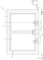
- FIG. 1 is a front view of a solar module system 1 (a view from the side of a solar module 4) according to an approach that is installed on an already installed window 10 (see FIG. 2).
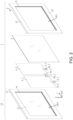
- FIG. 2 is an exploded perspective view of the solar module system 1, which is illustrated in FIG. 1 , and the window 10.
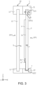
- FIG. 3 is a cross-sectional view (cross-sectional view along line A-A in FIG. 1 ) of the solar module system 1 and the window 10.
- the solar module system 1 includes a frame member 2, a support member 3, a solar module 4 (or a solar battery), wiring 5, a terminal 6, a terminal 7, wiring 8, and a junction box 9.
- two solar modules 4_1 and 4_2 are included as the solar module 4; however, the number of solar modules can be one or three or more.
- the solar modules 4_1 and 4_2 are not specifically discriminated, they may be described as the solar module 4.
- the solar module system 1 is arranged to face the window 10. To avoid complication, the wiring 8 and the junction box 9 are not illustrated in FIG. 2 and subsequent FIGs. below. In FIG. 2 , the terminal 7 is omitted.
- only one solar module system 1 is provided on one window 10; however, a plurality of solar module systems 1 may be provided on one window 10.
- the window 10 includes a window frame 11 and a transparent member (window glass) 12.
- the window frame 11 has an opening OP2 and holds the window glass 12 by having a peripheral portion of the window glass 12 inserted into a groove H that is formed along the opening OP2.
- the window frame 11 may be a structure itself where the window is installed.
- the solar module system 1 may be arranged on the side of a room with respect to the window 10, or may be arranged on an outdoor side. Having the solar module system 1 arranged indoors can prevent the solar module system 1 from being exposed to rain and wind. In a case where it is difficult to carry a solar module indoors because, for example, the solar module is too big, the solar module system 1 may be arranged outdoors. In arranging the solar module system 1 outdoors, its installation location is not limited to a window and may be arranged on an exterior wall.
- the frame member 2 has an opening OP1.
- the frame member 2 has a groove G for holding the support member 3 by having a peripheral portion of the support member 3 inserted into the groove G that is formed along the opening OP1.
- the frame member 2 can be coupled (connected) with the window frame 11 at at least part of a surface part thereof that opposes (faces) to the window frame 11 each other.
- the frame member 2 may be removable from the window frame 11. That is, the frame member 2 may be detachable from the window frame 11.
- the frame member 2 may be coupled with the window frame 11 by using a jig or adhesive (not illustrated). In the example of FIG.
- the frame member 2 has a square shape and includes: two side parts that are horizontal in the Z-axis direction and face each other; and two side parts that are horizontal in the Y-axis direction and face each other.
- the two side parts that are horizontal in the Y-axis direction and face each other are denoted as side parts 21, 22.
- the groove G may be provided at only the minimum required portion for holding the support member 3.
- the groove G may be provided at at least one pair out of the pairs of two facing side parts.
- the groove G (grooves G21, G22) may be provided only at a first side part 21 and a second side part 22 that opposes to the first side part 21, as illustrated in FIG. 3 . Details of the grooves G 21, G22 will be described later.
- the support member 3 includes a principal surface 3s and has the solar module 4 arranged on the principal surface 3s, directly supporting the solar module 4.
- the support member 3 is detachably arranged on the frame member 2 via the groove G, with the principal surface 3s on the side of the window glass 12.
- the support member 3 may have transparency.
- the support member 3 can have various shapes according to the shape of the frame member 2. In the following description, the support member 3 is assumed to be square-shaped for simplification.
- the support member 3 may be composed of transparent plastic.
- the support member 3 may include at least one of polycarbonate, vinyl chloride, and polyimide that are flame retardant materials. By using flame-retardant materials for the support member 3, the safety of the solar module 4 against fire or flames can be enhanced.
- the support member 3 may be of glass, screen, or the like.
- the support member 3 has a thickness T.
- the thickness T is 1 mm or more and 50 mm or less, for example.
- the thickness T being 1 mm or more can prevent deformation and makes it easy to handle the support member 3.
- the thickness T being 50 mm or less can reduce its weight and makes it easy to handle the support member 3.
- the support member 3 may be provided with a reinforcement member 31 to prevent deformation.
- FIG. 4 is an exploded perspective view of the support member 3 that is provided with the reinforcement member 31.
- the reinforcement member 31 is composed by combining members that are along at least either a diagonal line or side part of the support member 3, and is arranged on a surface of the support member 3.
- the reinforcement member 31 may be embedded inside the support member 3.
- the reinforcement member 31 may be formed of the same material as that of the support member 3, for example.
- the solar module 4 is arranged on (coupled to) the principal surface 3s of the support member 3.
- the solar module 4 may be coupled to the principal surface 3s by using tape or the like.
- the solar module 4 may be arranged by having a hollow formed on the principal surface 3s of the support member 3 and having the solar module 4 engaged into the hollow.
- the solar module 4 may be separatable from the principal surface 3s. That is, the solar module 4 may be detachable from the principal surface 3s of the support member 3.
- Each of two solar modules 4 includes a positive electrode 4a_1, 4a_2 and a negative electrode 4b_1, 4b_2.
- the positive electrodes 4a_1, 4a_2 may be collectively described as a positive electrode 4a
- the negative electrodes 4b_1, 4b_2 may be collectively described as the negative electrode 4b.
- the solar module 4 is a single-side light receiving solar cell (or battery) or a double-side light receiving solar cell (or battery). When the solar module 4 is a double-side light receiving solar cell, not only light incident from outside but also light reflected by an indoor wall or the like can be used for power generation.
- the solar module 4 may be a monocrystalline silicon solar cell (battery), a polycrystalline silicon solar cell (or battery), an amorphous silicon solar cell (or battery), an organic thin-film solar cell (or battery), a perovskite solar cell (or battery), or any other solar cells (or batteries).
- the solar module 4 can be made lighter in weight and this allows the solar module system 1 to be more easily installed.
- the solar module 4 is arranged on the principal surface 3s, so that the solar module 4 is located between the window glass 12 and the support member 3. This can increase the durability of the solar module 4. Further, this also can prevent dust, dirt, and the like from being adhered on the surface of the solar module 4.
- the number of solar modules 4 and/or the arrangement thereof may be freely changed to obtain necessary electromotive force.
- a space S is present between the support member 3 and the window glass 12.
- the presence of the space S can prevent heat generated by the solar module 4 from being directly transmitted to the window glass 12 and can prevent heat cracking or the like of the window glass 12. Further, the space S contributes to moderating transmission of outside air temperature to indoors and this can increase heat insulation.
- the space S is not necessarily hermetically sealed.
- the support member 3 may have breathability and a gap may be provided between the support member 3 and the frame member 2. Having the space S not hermetically sealed can prevent heat generated by the solar module 4 from being accumulated in the space S and can prevent the power generation efficiency of the solar module 4 from being degraded.
- a net-like or spongy breathable member may be arranged in the gap between the support member 3 and the frame member 2 to prevent dust from getting into the space S.
- the wiring 5 electrically connects the solar modules 4 via their respective negative electrodes 4b and positive electrodes 4a.
- the wiring 5 may be detachably arranged on the support member 3, or may be embedded in the support member 3.
- the wiring 5 has a shape according to the number of solar modules 4 and/or the shape thereof.
- the shape of the solar module 4 include the positions of the electrodes 4a and 4b of the solar module 4.
- the terminal 6 (6_1, 6_2) is a terminal for electrically connecting the solar module 4 to the terminal 7 (7_1, 7_2) of the frame member 2.
- the terminal 6_1 and the terminal 6_2 are arranged on the support member 3 so that the terminal 6_1 contacts the electrode 4a_1 of the solar module 4_1 and the terminal 6_2 contacts the negative electrode 4b_2 of the solar module 4_2.
- the terminal 6 (6_1, 6_2) may be a clip-type terminal that clips the support member 3.
- the terminal 6 may be detachably arranged on the support member 3.
- the terminal 6 may be arranged at an edge of the support member 3 so that part or the whole thereof is invisible from outside in a state where the support member 3 is fixed onto the frame member 2. For example, when the support member 3 is fixed by the groove G of the frame member 2, the terminal 6 may be arranged so as to be hidden by the groove G. This can improve the designability of the solar module system 1.
- the terminal 7 (7_1, 7_2) is a terminal for taking out an output of the solar module 4 to outside.
- the terminal 7 is arranged on the frame member 2 so as to contact the terminal 6 (6_1, 6_2) when the support member 3 is fixed onto the frame member 2.
- the terminal 7 may be arranged in the groove G of the frame member 2. This lowers the visibility of the terminal 7, which can improve the designability of the solar module system 1.
- the position of the terminal 6 has to be different. Therefore, the terminal 6 may be arranged at any point of the support member 3.
- the terminal 7 also may be arranged at any point of the frame member 2 according to the position of the terminal 6.
- a rail (not illustrated) may be provided on the groove G so as to allow the terminal 7 to move on the rail.
- the wiring 8 is wiring for taking out an output of the solar module 4 from the terminal 7 to outside.
- the wiring 8 electrically connects the terminal 7 and the junction box 9.
- the junction box 9 integrates outputs from a plurality of solar module systems 1.
- the junction box 9 is arranged outside the frame member 2.
- this does not limit the arrangement of the junction box 9 and the junction box 9 may be arranged inside the frame member 2.
- the wiring 8 is also arranged inside the frame member 2. This can improve the designability in comparison with a case where the junction box 9 is arranged outside the frame member 2.
- a state where the support member 3 is fixed onto the frame member 2 includes a state where the support member 3 is loosely fit to the groove G of the frame member 2.
- the window 10 is not illustrated to avoid complication.
- the groove G21 of the side part 21 of the frame member 2 is formed so that a width W of the groove G21 at at least part of the groove G21, the part including the opening OP 21, that is to say, the width on an opening side of the groove G21, is larger in a direction opposite to the depth direction of the groove G21.
- the groove G21 is deeper than the groove G22. The following describes how to fix the support member 3 onto the frame member 2 with reference to FIGS. 5A to 5C .
- one side part out of edge sides of the support member 3 is inserted into the opening OP2 of the groove G21 of the side part 21 of the frame member 2. Then, while the support member 3 is being slid via the groove G21 in the direction of the side part 21, another side part that opposes to the one side part of the support member 3 is moved in the direction of the side part 22 (direction of an arrow A1). That is, the support member 3 is rotated in the direction of the arrow A1, with the groove G 21 as an axis (see FIG. 5A .).
- the support member 3 is moved in the direction from the side part 21 to the side part 22 (direction of an arrow A2), to engage the other side part of the support member 3 into the groove G22 (see FIG. 5C .). Since the groove G21 is deeper than the groove G22, the support member 3 does not come off from the groove G21 when the support member 3 is moved in the direction of the arrow A2.
- the above series of operations makes the support member 3 fixed onto the frame member 2 by the groove G21 and the groove G22. To remove the support member 3 from the frame member 2, the above series of operation is performed in inverse order.
- the side part 21 may be a side part on a side opposite to the gravity direction.
- the support member 3 may be firmly fixed onto the frame member 2 by a screw or the like. Firmly fixing the support member 3 onto the frame member 2 can prevent deformation of the support member 3.
- the above-described mounting method does not necessitate removing the frame member 2 from the window 10 and therefore, the support member 3 can be fixed while the frame member 2 is being fixed onto the window 10. Furthermore, also in removing the support member 3 from the frame member 2, the support member 3 can be removed while the frame member 2 is being fixed onto the window 10.
- the support member 3 may be fixed onto the frame member 2 in a way other than that described above.
- the frame member 2 is separated into a plurality of pieces in the Z-axis direction or another direction and after the support member 3 is housed in the grooves of the frame member 2, the frame member 2 is recombined to fix the support member 3 onto the frame member 2.
- a solar module system that can be installed and removed without interfering with an already installed window can be provided.
- a solar module can be easily detachably mounted on a window without requiring much work. This allows the solar module 4 to be easily replaced when it becomes defective.
- the solar module 4 and the terminal 6 may be detachable from the support member 3 and in this case, it is possible to replace only the solar module or only the terminal.
- the solar module system is easily detachable, this approach is effective even in a case where the solar module is not intended to be placed at the same location for a long period of time, such as when the module is installed in a rental property.
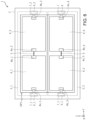
- FIG. 6 is a front view of the solar module system 1 that includes two support members 3.
- solar modules 4_1, 4_2 and solar modules 4_3, 4_4 are arranged on two support members 3_1, 3_2, respectively.
- the support member 3 when the solar module system 1 becomes bigger, the support member 3 also becomes bigger and heavier and this increases the burden on a user who attaches/detaches the solar module system 1.
- each of the support members 3 can be smaller and this can reduce the burden on a user who attaches/detaches the support members 3 to/from the frame member 2.
- the area of the opening OP1 of the frame member 2 is almost the same as the area of the opening OP2 of the window frame 11 and the solar module system 1 is installed so as to cover the whole surface of the opening OP2.
- the solar module system 1 may be arranged so as to cover only part of the opening OP2, that is, only part of an exposed transparent member. More specifically, the area of the opening OP1 may be smaller than the area of the opening OP2 and the shape of the opening OP1 may be such as to fit within the opening OP2. This makes it possible to use part of the window 10 for its original purpose.
- FIG. 8 illustrates a solar module system 1 of the third modification.
- a terminal (positive-electrode side terminal) 6a and a terminal (negative-electrode side terminal) 6b that have mutually different shapes are provided.
- the terminal 6a is connected with the positive electrode 4a_1 of the solar module 4.
- the terminal 6b is connected with the negative electrode 4b_2 of the solar module 4.
- FIG. 9A and FIG. 9B are enlarged cross-sectional views of a contact part between the electrode 4a_1 and the terminal 6a and a contact part between the electrode 4b_2 and the terminal 6b of the solar module system 1 illustrated in FIG. 8 .
- the positive electrode 4a_1 has a concave part and the terminal 6a has a convex part, for example.
- the negative electrode 4b_2 has a convex part and the terminal 6b has a concave part.
- the terminal 6a or the terminal 6b does not fit the negative electrode 4b_2 or the positive electrode 4a_1 and therefore, the terminal 6a or the terminal 6b cannot be arranged, which allows a user to recognize that the orientation of the solar module 4 is wrong. This can prevent the solar module 4 from being short-circuited.
- the shapes of the electrodes 4a_1, 4b_2 and the shapes of the terminals 6a, 6b are not limited to those in the above description.
- the solar module system 1 be made more compact (thinner) so that the solar module system 1 does not occupy the space.
- grooves G21, G22 are formed between the frame member 2 and the window frame 11 as illustrated in FIG. 10 .
- grooves G21, G22 are formed between the frame member 2 and the window glass 12 as illustrated in FIG. 11 .
- the above-described structure of the frame member 2 allows a reduction of the width of the frame member 2 in the X-axis direction, which makes it possible to reduce the thickness of the whole of the solar module system 1.
- a distance (space S) between the window glass 12 and the support member 3 is small and therefore, to prevent heat generated by the solar module 4 from being transmitted to the window glass 12, the support member 3 is arranged so that the principal surface 3s on which the solar module 4 is arranged is on the room side (an opposite side to the window glass 12). That is, the solar module 4 is arranged on the room side of the support member 3. At this time, the support member 3 may be in contact with the window glass 12.
- the principal surface 3s of the support member 3 is on the room side (an opposite side to the window glass 12); however, the principal surface 3s may be on the window glass 12 side.
- a solar module system comprising:
- Clause 7 The solar module system according to any one of clauses 1 to 6 comprising a plurality of the support members.
- Clause 8 The solar module system according to any one of clauses 1 to 7, wherein an area of an opening of the frame member is smaller than an area of the transparent member.
- Clause 10 The solar module system according to any one of clauses 1 to 9, wherein the support member includes at least one of polycarbonate, vinyl chloride, and polyimide.
- Clause 11 The solar module system according to any one of clauses 1 to 10, wherein a thickness of the support member is 1 mm or more and 50 mm or less.
- Clause 12 The solar module system according to any one of clauses 1 to 11, wherein the support member includes a reinforcement member along at least either a diagonal line or side part of the support member.
- a solar system comprising:
Landscapes
- Engineering & Computer Science (AREA)
- Architecture (AREA)
- Civil Engineering (AREA)
- Structural Engineering (AREA)
- Photovoltaic Devices (AREA)
- Special Wing (AREA)
Abstract
Description
- Approaches described herein relate to a solar module system, a solar system, and a mounting method.
- With a recent increasing demand for solar power generation, an attempt to increase the amount of power generation has been made by placing a solar cell (or battery) or a solar module not only on roofs or roof tops but also on windows of structures.
- In one example of proposed methods for placing a solar cell on windows, a hole or hollow is formed on a window and a solar cell is embedded in the hole or hollow. However, such a method may lead to the degradation of functions of the window such as heat resistance and/or mechanical resistance.
- There is another idea of embedding a solar cell inside window glass. However, if lifespans of a solar cell and window glass do not match, both the solar cell and window glass have to be replaced when either one of them has passed, which is uneconomical. In addition, to retrofit a solar cell on an already-existing window, it is necessary to replace window glass of the already-existing window with one having a solar cell embedded therein, which leads to an increase of work costs.
- There has been another method proposed in which a member having a solar cell embedded therein is mounted independently of a window. In this method, although it is easy to mount and remove a member having a solar cell embedded therein, it is necessary for a person with expertise to perform a connection work for taking out an output of the solar cell to the outside.
-
-
FIG. 1 is a front view of a solar module system according to one approach; -
FIG. 2 is an exploded perspective view of the solar module system according to the approach; -
FIG. 3 is a cross-sectional view of the solar module system according to the approach; -
FIG. 4 is an exploded perspective view that illustrates a support member and a reinforcement member included in the support member; -
FIGS. 5A to 5C each is a cross-sectional view that illustrates a method of mounting the support member; -
FIG. 6 is a cross-sectional view that illustrates another example of the solar module system according to the approach; -
FIG. 7 is a front view that illustrates still another example of the solar module system according to the approach; -
FIG. 8 is a front view that illustrates still another example of the solar module system according to the approach; -
FIG. 9A and FIG. 9B are enlarged cross-sectional views of contact parts between electrodes of solar modules and terminals in the solar module system illustrated inFIG. 8 ; -
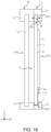
FIG. 10 is a cross-sectional view of the solar module system according to a fourth modification; and -
FIG. 11 is a cross-sectional view of another example of the solar module system according to the fourth modification. - According to one approach, a solar module system includes: a support member that has a principal surface; a solar module arranged on the principal surface; a first terminal arranged on the support member and electrically connected with an electrode of the solar module; a frame member configured to hold the support member such that the solar module opposes to a transparent member; and a second terminal arranged on the frame member and electrically connected with the first terminal of the support member being held by the frame member.
- Hereinafter, an approach of the present invention will be described with reference to the drawings. The approach is not restrictive of the present invention. The drawings are schematic or conceptual and a ratio between portions or the like is not necessarily the same as the actual one. In the description and drawings, the same components as the ones described earlier for aforementioned drawings are denoted by the same reference signs to appropriately omit detailed description thereof.
- The rectangular coordinate system of X, Y, and Z axes are adopted for convenience of description, as illustrated in the drawings and the like.
-
FIG. 1 is a front view of a solar module system 1 (a view from the side of a solar module 4) according to an approach that is installed on an already installed window 10 (seeFIG. 2). FIG. 2 is an exploded perspective view of thesolar module system 1, which is illustrated inFIG. 1 , and thewindow 10.FIG. 3 is a cross-sectional view (cross-sectional view along line A-A inFIG. 1 ) of thesolar module system 1 and thewindow 10. - The
solar module system 1 includes aframe member 2, asupport member 3, a solar module 4 (or a solar battery),wiring 5, aterminal 6, aterminal 7,wiring 8, and ajunction box 9. In this example, two solar modules 4_1 and 4_2 are included as thesolar module 4; however, the number of solar modules can be one or three or more. When the solar modules 4_1 and 4_2 are not specifically discriminated, they may be described as thesolar module 4. Thesolar module system 1 is arranged to face thewindow 10. To avoid complication, thewiring 8 and thejunction box 9 are not illustrated inFIG. 2 and subsequent FIGs. below. InFIG. 2 , theterminal 7 is omitted. In the illustrations ofFIG. 1 to FIG. 3 , only onesolar module system 1 is provided on onewindow 10; however, a plurality ofsolar module systems 1 may be provided on onewindow 10. - The
window 10 includes awindow frame 11 and a transparent member (window glass) 12. Thewindow frame 11 has an opening OP2 and holds thewindow glass 12 by having a peripheral portion of thewindow glass 12 inserted into a groove H that is formed along the opening OP2. Thewindow frame 11 may be a structure itself where the window is installed. - The
solar module system 1 may be arranged on the side of a room with respect to thewindow 10, or may be arranged on an outdoor side. Having thesolar module system 1 arranged indoors can prevent thesolar module system 1 from being exposed to rain and wind. In a case where it is difficult to carry a solar module indoors because, for example, the solar module is too big, thesolar module system 1 may be arranged outdoors. In arranging thesolar module system 1 outdoors, its installation location is not limited to a window and may be arranged on an exterior wall. - The
frame member 2 has an opening OP1. Theframe member 2 has a groove G for holding thesupport member 3 by having a peripheral portion of thesupport member 3 inserted into the groove G that is formed along the opening OP1. Theframe member 2 can be coupled (connected) with thewindow frame 11 at at least part of a surface part thereof that opposes (faces) to thewindow frame 11 each other. In addition, theframe member 2 may be removable from thewindow frame 11. That is, theframe member 2 may be detachable from thewindow frame 11. Theframe member 2 may be coupled with thewindow frame 11 by using a jig or adhesive (not illustrated). In the example ofFIG. 2 , theframe member 2 has a square shape and includes: two side parts that are horizontal in the Z-axis direction and face each other; and two side parts that are horizontal in the Y-axis direction and face each other. Here, the two side parts that are horizontal in the Y-axis direction and face each other are denoted asside parts - The groove G may be provided at only the minimum required portion for holding the
support member 3. As for the square-shaped frame member 2, the groove G may be provided at at least one pair out of the pairs of two facing side parts. For example, the groove G (grooves G21, G22) may be provided only at afirst side part 21 and asecond side part 22 that opposes to thefirst side part 21, as illustrated inFIG. 3 . Details of thegrooves G 21, G22 will be described later. - The
support member 3 includes aprincipal surface 3s and has thesolar module 4 arranged on theprincipal surface 3s, directly supporting thesolar module 4. Thesupport member 3 is detachably arranged on theframe member 2 via the groove G, with theprincipal surface 3s on the side of thewindow glass 12. Thesupport member 3 may have transparency. Thesupport member 3 can have various shapes according to the shape of theframe member 2. In the following description, thesupport member 3 is assumed to be square-shaped for simplification. - The
support member 3 may be composed of transparent plastic. Thesupport member 3 may include at least one of polycarbonate, vinyl chloride, and polyimide that are flame retardant materials. By using flame-retardant materials for thesupport member 3, the safety of thesolar module 4 against fire or flames can be enhanced. Thesupport member 3 may be of glass, screen, or the like. - The
support member 3 has a thickness T. The thickness T is 1 mm or more and 50 mm or less, for example. The thickness T being 1 mm or more can prevent deformation and makes it easy to handle thesupport member 3. The thickness T being 50 mm or less can reduce its weight and makes it easy to handle thesupport member 3. - The
support member 3 may be provided with areinforcement member 31 to prevent deformation.FIG. 4 is an exploded perspective view of thesupport member 3 that is provided with thereinforcement member 31. Thereinforcement member 31 is composed by combining members that are along at least either a diagonal line or side part of thesupport member 3, and is arranged on a surface of thesupport member 3. Thereinforcement member 31 may be embedded inside thesupport member 3. Thereinforcement member 31 may be formed of the same material as that of thesupport member 3, for example. - The
solar module 4 is arranged on (coupled to) theprincipal surface 3s of thesupport member 3. Thesolar module 4 may be coupled to theprincipal surface 3s by using tape or the like. Alternatively, thesolar module 4 may be arranged by having a hollow formed on theprincipal surface 3s of thesupport member 3 and having thesolar module 4 engaged into the hollow. Thesolar module 4 may be separatable from theprincipal surface 3s. That is, thesolar module 4 may be detachable from theprincipal surface 3s of thesupport member 3. - Each of two
solar modules 4 includes a positive electrode 4a_1, 4a_2 and a negative electrode 4b_1, 4b_2. In the following description, the positive electrodes 4a_1, 4a_2 may be collectively described as apositive electrode 4a and the negative electrodes 4b_1, 4b_2 may be collectively described as thenegative electrode 4b. Thesolar module 4 is a single-side light receiving solar cell (or battery) or a double-side light receiving solar cell (or battery). When thesolar module 4 is a double-side light receiving solar cell, not only light incident from outside but also light reflected by an indoor wall or the like can be used for power generation. - The
solar module 4 may be a monocrystalline silicon solar cell (battery), a polycrystalline silicon solar cell (or battery), an amorphous silicon solar cell (or battery), an organic thin-film solar cell (or battery), a perovskite solar cell (or battery), or any other solar cells (or batteries). In the case of using an organic thin-film solar cell or a perovskite solar cell as thesolar module 4, thesolar module 4 can be made lighter in weight and this allows thesolar module system 1 to be more easily installed. - The
solar module 4 is arranged on theprincipal surface 3s, so that thesolar module 4 is located between thewindow glass 12 and thesupport member 3. This can increase the durability of thesolar module 4. Further, this also can prevent dust, dirt, and the like from being adhered on the surface of thesolar module 4. - The number of
solar modules 4 and/or the arrangement thereof may be freely changed to obtain necessary electromotive force. - A space S is present between the
support member 3 and thewindow glass 12. The presence of the space S can prevent heat generated by thesolar module 4 from being directly transmitted to thewindow glass 12 and can prevent heat cracking or the like of thewindow glass 12. Further, the space S contributes to moderating transmission of outside air temperature to indoors and this can increase heat insulation. - The space S is not necessarily hermetically sealed. For example, the
support member 3 may have breathability and a gap may be provided between thesupport member 3 and theframe member 2. Having the space S not hermetically sealed can prevent heat generated by thesolar module 4 from being accumulated in the space S and can prevent the power generation efficiency of thesolar module 4 from being degraded. A net-like or spongy breathable member may be arranged in the gap between thesupport member 3 and theframe member 2 to prevent dust from getting into the space S. - The
wiring 5 electrically connects thesolar modules 4 via their respectivenegative electrodes 4b andpositive electrodes 4a. Thewiring 5 may be detachably arranged on thesupport member 3, or may be embedded in thesupport member 3. Thewiring 5 has a shape according to the number ofsolar modules 4 and/or the shape thereof. Here, the shape of thesolar module 4 include the positions of theelectrodes solar module 4. - The terminal 6 (6_1, 6_2) is a terminal for electrically connecting the
solar module 4 to the terminal 7 (7_1, 7_2) of theframe member 2. The terminal 6_1 and the terminal 6_2 are arranged on thesupport member 3 so that the terminal 6_1 contacts the electrode 4a_1 of the solar module 4_1 and the terminal 6_2 contacts the negative electrode 4b_2 of the solar module 4_2. The terminal 6 (6_1, 6_2) may be a clip-type terminal that clips thesupport member 3. Theterminal 6 may be detachably arranged on thesupport member 3. Theterminal 6 may be arranged at an edge of thesupport member 3 so that part or the whole thereof is invisible from outside in a state where thesupport member 3 is fixed onto theframe member 2. For example, when thesupport member 3 is fixed by the groove G of theframe member 2, theterminal 6 may be arranged so as to be hidden by the groove G. This can improve the designability of thesolar module system 1. - The terminal 7 (7_1, 7_2) is a terminal for taking out an output of the
solar module 4 to outside. Theterminal 7 is arranged on theframe member 2 so as to contact the terminal 6 (6_1, 6_2) when thesupport member 3 is fixed onto theframe member 2. Theterminal 7 may be arranged in the groove G of theframe member 2. This lowers the visibility of theterminal 7, which can improve the designability of thesolar module system 1. - According to the variation of the number of
solar modules 4 and/or the shape thereof, the position of theterminal 6 has to be different. Therefore, theterminal 6 may be arranged at any point of thesupport member 3. In addition, theterminal 7 also may be arranged at any point of theframe member 2 according to the position of theterminal 6. For example, a rail (not illustrated) may be provided on the groove G so as to allow theterminal 7 to move on the rail. - The
wiring 8 is wiring for taking out an output of thesolar module 4 from theterminal 7 to outside. Thewiring 8 electrically connects theterminal 7 and thejunction box 9. - The
junction box 9 integrates outputs from a plurality ofsolar module systems 1. InFIG. 1 , thejunction box 9 is arranged outside theframe member 2. However, this does not limit the arrangement of thejunction box 9 and thejunction box 9 may be arranged inside theframe member 2. In this case, thewiring 8 is also arranged inside theframe member 2. This can improve the designability in comparison with a case where thejunction box 9 is arranged outside theframe member 2. - Next, an example of fixing the
support member 3 onto theframe member 2 will be described with reference toFIGS. 5A to 5C . Here, a state where thesupport member 3 is fixed onto theframe member 2 includes a state where thesupport member 3 is loosely fit to the groove G of theframe member 2. Thewindow 10 is not illustrated to avoid complication. - As illustrated in
FIGS. 5A to 5C , the groove G21 of theside part 21 of theframe member 2 is formed so that a width W of the groove G21 at at least part of the groove G21, the part including theopening OP 21, that is to say, the width on an opening side of the groove G21, is larger in a direction opposite to the depth direction of the groove G21. In addition, the groove G21 is deeper than the groove G22. The following describes how to fix thesupport member 3 onto theframe member 2 with reference toFIGS. 5A to 5C . - First, one side part out of edge sides of the
support member 3 is inserted into the opening OP2 of the groove G21 of theside part 21 of theframe member 2. Then, while thesupport member 3 is being slid via the groove G21 in the direction of theside part 21, another side part that opposes to the one side part of thesupport member 3 is moved in the direction of the side part 22 (direction of an arrow A1). That is, thesupport member 3 is rotated in the direction of the arrow A1, with thegroove G 21 as an axis (seeFIG. 5A .). - The above operation makes the
support member 3 parallel to the window glass 12 (window 10) (seeFIG. 5B ). Since the groove G21 is deeper than the groove G22, thesupport member 3 is engaged only in the groove G21 in this state. - Next, the
support member 3 is moved in the direction from theside part 21 to the side part 22 (direction of an arrow A2), to engage the other side part of thesupport member 3 into the groove G22 (seeFIG. 5C .). Since the groove G21 is deeper than the groove G22, thesupport member 3 does not come off from the groove G21 when thesupport member 3 is moved in the direction of the arrow A2. The above series of operations makes thesupport member 3 fixed onto theframe member 2 by the groove G21 and the groove G22. To remove thesupport member 3 from theframe member 2, the above series of operation is performed in inverse order. - The
side part 21 may be a side part on a side opposite to the gravity direction. In removing thesupport member 3 from theframe member 2, it is necessary to perform the operation of moving thesupport member 3 in a direction opposite to the arrow A2. Therefore, when theside part 21 is on a side opposite to the gravity direction, the above operation is performed in a direction opposite to the gravity direction and this can prevent thesupport member 3 from being spontaneously detached from theframe member 2 due to vibration or the like. - After the above series of operations, the
support member 3 may be firmly fixed onto theframe member 2 by a screw or the like. Firmly fixing thesupport member 3 onto theframe member 2 can prevent deformation of thesupport member 3. - In addition, the above-described mounting method does not necessitate removing the
frame member 2 from thewindow 10 and therefore, thesupport member 3 can be fixed while theframe member 2 is being fixed onto thewindow 10. Furthermore, also in removing thesupport member 3 from theframe member 2, thesupport member 3 can be removed while theframe member 2 is being fixed onto thewindow 10. - The
support member 3 may be fixed onto theframe member 2 in a way other than that described above. In one possible example, theframe member 2 is separated into a plurality of pieces in the Z-axis direction or another direction and after thesupport member 3 is housed in the grooves of theframe member 2, theframe member 2 is recombined to fix thesupport member 3 onto theframe member 2. - As described above, according to the approach, a solar module system that can be installed and removed without interfering with an already installed window can be provided. In addition, a solar module can be easily detachably mounted on a window without requiring much work. This allows the
solar module 4 to be easily replaced when it becomes defective. - In addition, the
solar module 4 and theterminal 6 may be detachable from thesupport member 3 and in this case, it is possible to replace only the solar module or only the terminal. - Furthermore, since the solar module system is easily detachable, this approach is effective even in a case where the solar module is not intended to be placed at the same location for a long period of time, such as when the module is installed in a rental property.
- Next, a first modification of the approach will be described with reference to
FIG. 6 . InFIG. 1 , thesupport member 3 is comprised of one piece; however, thesupport member 3 may be comprised of a plurality of pieces.FIG. 6 is a front view of thesolar module system 1 that includes twosupport members 3. In an example illustrated inFIG. 6 , solar modules 4_1, 4_2 and solar modules 4_3, 4_4 are arranged on two support members 3_1, 3_2, respectively. In the case of asupport member 3 comprised of one piece, when thesolar module system 1 becomes bigger, thesupport member 3 also becomes bigger and heavier and this increases the burden on a user who attaches/detaches thesolar module system 1. On the other hand, by using thesupport member 3 comprised of a plurality of pieces, each of thesupport members 3 can be smaller and this can reduce the burden on a user who attaches/detaches thesupport members 3 to/from theframe member 2. - Next, a second modification of the approach will be described with reference to
FIG. 7 . InFIG. 1 , the area of the opening OP1 of theframe member 2 is almost the same as the area of the opening OP2 of thewindow frame 11 and thesolar module system 1 is installed so as to cover the whole surface of the opening OP2. However, as illustrated inFIG. 7 , thesolar module system 1 may be arranged so as to cover only part of the opening OP2, that is, only part of an exposed transparent member. More specifically, the area of the opening OP1 may be smaller than the area of the opening OP2 and the shape of the opening OP1 may be such as to fit within the opening OP2. This makes it possible to use part of thewindow 10 for its original purpose. - Next, a third modification of the approach will be described with reference to
FIG. 8 . When a user with no expertise places thesolar module 4, a short circuit of thesolar module 4 may occur due to placement in a wrong orientation (for example, upside down or reversely). -
FIG. 8 illustrates asolar module system 1 of the third modification. As theterminal 6, a terminal (positive-electrode side terminal) 6a and a terminal (negative-electrode side terminal) 6b that have mutually different shapes are provided. The terminal 6a is connected with the positive electrode 4a_1 of thesolar module 4. The terminal 6b is connected with the negative electrode 4b_2 of thesolar module 4. -
FIG. 9A and FIG. 9B are enlarged cross-sectional views of a contact part between the electrode 4a_1 and the terminal 6a and a contact part between the electrode 4b_2 and the terminal 6b of thesolar module system 1 illustrated inFIG. 8 . As illustrated inFIG. 9A , the positive electrode 4a_1 has a concave part and the terminal 6a has a convex part, for example. Similarly, as illustrated inFIG. 9B , the negative electrode 4b_2 has a convex part and the terminal 6b has a concave part. - This allows the shape of the terminal 6a and the shape of the positive electrode 4a_1 to fit each other and the shape of the terminal 6b and the shape of the negative electrode 4b_1 to fit each other; and does not allow the shape of the terminal 6a and the shape of the negative electrode 4b_2 to fit and the shape of the terminal 6b and the shape of the positive electrode 4a_1 to fit.
- According to the above configuration, even when an attempt is made to place the
solar module 4 in a wrong orientation, the terminal 6a or the terminal 6b does not fit the negative electrode 4b_2 or the positive electrode 4a_1 and therefore, the terminal 6a or the terminal 6b cannot be arranged, which allows a user to recognize that the orientation of thesolar module 4 is wrong. This can prevent thesolar module 4 from being short-circuited. It is noted that the shapes of the electrodes 4a_1, 4b_2 and the shapes of theterminals - Next, a fourth modification of the approach will be described with reference to
FIG. 10 andFIG. 11 . In light of designability and the like, it may be desirable that thesolar module system 1 be made more compact (thinner) so that thesolar module system 1 does not occupy the space. - In this modification, when the
frame member 2 is arranged on thewindow frame 11 or thewindow glass 12, grooves G21, G22 are formed between theframe member 2 and thewindow frame 11 as illustrated inFIG. 10 . Alternatively, according to the shape of thewindow 10, grooves G21, G22 are formed between theframe member 2 and thewindow glass 12 as illustrated inFIG. 11 . - In either of
FIG. 10 orFIG. 11 , the above-described structure of theframe member 2 allows a reduction of the width of theframe member 2 in the X-axis direction, which makes it possible to reduce the thickness of the whole of thesolar module system 1. A distance (space S) between thewindow glass 12 and thesupport member 3 is small and therefore, to prevent heat generated by thesolar module 4 from being transmitted to thewindow glass 12, thesupport member 3 is arranged so that theprincipal surface 3s on which thesolar module 4 is arranged is on the room side (an opposite side to the window glass 12). That is, thesolar module 4 is arranged on the room side of thesupport member 3. At this time, thesupport member 3 may be in contact with thewindow glass 12. In the examples ofFIG. 10 andFIG. 11 , theprincipal surface 3s of thesupport member 3 is on the room side (an opposite side to the window glass 12); however, theprincipal surface 3s may be on thewindow glass 12 side. - While certain approaches have been described, these approaches have been presented by way of example only, and are not intended to limit the scope of the inventions. Indeed, the novel approaches described herein may be embodied in a variety of other forms; furthermore, various omissions, substitutions and changes in the form of the approaches described herein may be made without departing from the scopes of the inventions. The accompanying claims and their equivalents are intended to cover such forms or modifications as would fall within the scopes of the inventions.
- The approaches as described before may be configured as below.
-
Clause 1. A solar module system comprising: - a support member that has a principal surface;
- a solar module arranged on the principal surface;
- a first terminal arranged on the support member and electrically connected with an electrode of the solar module;
- a frame member configured to hold the support member such that the solar module opposes to a transparent member; and
- a second terminal arranged on the frame member and electrically connected with the first terminal of the support member being held by the frame member.
-
Clause 2. The solar module system according toclause 1, wherein - the support member is square-shaped;
- the frame member is square-shaped;
- the frame member has a first side part and a second side part facing the first side part, and has grooves formed on at least both the first side part and the second side part; and
- the support member is held by the frame member by being engaged into the groove.
-
Clause 3. The solar module system according toclause 2, wherein
the second terminal is arranged in the groove formed on the second side. -
Clause 4. The solar module system according toclause - a width of a first groove, the first groove being the groove formed on the first side part, becomes larger at least partially on an opening side of the first groove toward a side opposite to a depth direction of the first groove; and
- the first groove formed on the first side part, is deeper than the second groove formed on the second side part.
-
Clause 5. The solar module system according toclause 4, wherein
the first side part is a side part on a side opposite to the gravity direction. -
Clause 6. The solar module system according to any one ofclauses 1 to 5, wherein - the first terminal includes:
- a positive-electrode side first terminal that is electrically connected with a positive electrode of the solar module; and
- a negative-electrode side first terminal that is electrically connected with a negative electrode of the solar module; and wherein
- a shape of the positive-electrode side first terminal and a shape of the positive electrode fit each other;
- a shape of the negative-electrode side first terminal and a shape of the negative electrode fit each other;
- the shape of the positive-electrode side first terminal and the shape of the negative electrode do not fit; and
- the shape of the negative-electrode side first terminal and the shape of the positive electrode do not fit.
-
Clause 7. The solar module system according to any one ofclauses 1 to 6 comprising a plurality of the support members. -
Clause 8. The solar module system according to any one ofclauses 1 to 7, wherein
an area of an opening of the frame member is smaller than an area of the transparent member. -
Clause 9. The solar module system according to any one ofclauses 1 to 8, wherein
the transparent member is window glass. -
Clause 10. The solar module system according to any one ofclauses 1 to 9, wherein
the support member includes at least one of polycarbonate, vinyl chloride, and polyimide. -
Clause 11. The solar module system according to any one ofclauses 1 to 10, wherein
a thickness of the support member is 1 mm or more and 50 mm or less. -
Clause 12. The solar module system according to any one ofclauses 1 to 11, wherein
the support member includes a reinforcement member along at least either a diagonal line or side part of the support member. - Clause 13. A solar system comprising:
- a plurality of the solar module systems according to any one of
clauses 1 to 12; - a junction box configured to integrate outputs from the plurality of the solar module systems; and
- wiring configured to electrically connect the second terminal and the junction box.
- Clause 14. A method of mounting a support member, wherein
- the support member is held by a frame member;
- the support member has a solar module arranged on a principal surface thereof and includes a first terminal that is electrically connected to an electrode of the solar module;
- the frame member holds the support member so that the solar module opposes to a transparent member;
- the frame member has a first side part and a second side part that opposes to the first side part;
- a first groove is formed on the first side part and a second groove is formed on the second side part;
- a width of the first groove becomes larger at least partially on a side of an opening of the first groove in a direction opposite to a depth direction of the first groove; and
- the first groove is deeper than the second groove,
- the method of mounting the support member comprising:
- inserting one side part out of edge sides of the support member into the opening of the first groove;
- moving another side part that opposes to the one side part in a direction of the second side part of the frame member, the other side part being one of the edge sides of the support member, the moving being performed while the one side part of the support member is being slid via the first groove in a direction of the first side part of the frame member; and
- engaging the other side part of the support member into the second groove of the frame member by moving the support member in a direction from the first side part to the second side part.
Claims (14)
- A solar module system comprising:a support member that has a principal surface;a solar module arranged on the principal surface;a first terminal arranged on the support member and electrically connected with an electrode of the solar module;a frame member configured to hold the support member such that the solar module opposes to a transparent member; anda second terminal arranged on the frame member and electrically connected with the first terminal of the support member being held by the frame member.
- The solar module system according to claim 1, whereinthe support member is square-shaped;the frame member is square-shaped;the frame member has a first side part and a second side part facing the first side part, and has grooves formed on at least both the first side part and the second side part; andthe support member is held by the frame member by being engaged into the groove.
- The solar module system according to claim 2, wherein
the second terminal is arranged in the groove formed on the second side part. - The solar module system according to claim 2 or 3, whereina width of a first groove, the first groove being the groove formed on the first side part, becomes larger at least partially on an opening side of the first groove toward a side opposite to a depth direction of the first groove; andthe first groove formed on the first side part, is deeper than the second groove formed on the second side part.
- The solar module system according to claim 4, wherein
the first side part is a side part on a side opposite to the gravity direction. - The solar module system according to any one of claims 1 to 5, wherein
the first terminal includes:a positive-electrode side first terminal that is electrically connected with a positive electrode of the solar module; anda negative-electrode side first terminal that is electrically connected with a negative electrode of the solar module; and whereina shape of the positive-electrode side first terminal and a shape of the positive electrode fit each other;a shape of the negative-electrode side first terminal and a shape of the negative electrode fit each other;the shape of the positive-electrode side first terminal and the shape of the negative electrode do not fit; andthe shape of the negative-electrode side first terminal and the shape of the positive electrode do not fit. - The solar module system according to any one of claims 1 to 6 comprising a plurality of the support members.
- The solar module system according to any one of claims 1 to 7, wherein
an area of an opening of the frame member is smaller than an area of the transparent member. - The solar module system according to any one of claims 1 to 8, wherein
the transparent member is window glass. - The solar module system according to any one of claims 1 to 9, wherein
the support member includes at least one of polycarbonate, vinyl chloride, and polyimide. - The solar module system according to any one of claims 1 to 10, wherein
a thickness of the support member is 1 mm or more and 50 mm or less. - The solar module system according to any one of claims 1 to 11, wherein
the support member includes a reinforcement member along at least either a diagonal line or side part of the support member. - A solar system comprising:a plurality of the solar module systems according to any one of claims 1 to 12;a junction box configured to integrate outputs from the plurality of the solar module systems; andwiring configured to electrically connect the second terminal and the junction box.
- A method of mounting a support member, whereinthe support member is held by a frame member;the support member has a solar module arranged on a principal surface thereof and includes a first terminal that is electrically connected to an electrode of the solar module;the frame member holds the support member so that the solar module opposes to a transparent member;the frame member has a first side part and a second side part that opposes to the first side part;a first groove is formed on the first side part and a second groove is formed on the second side part;a width of the first groove becomes larger at least partially on a side of an opening of the first groove in a direction opposite to a depth direction of the first groove; andthe first groove is deeper than the second groove,the method of mounting the support member comprising:inserting one side part out of edge sides of the support member into the opening of the first groove;moving another side part that opposes to the one side part in a direction of the second side part of the frame member, the other side part being one of the edge sides of the support member, the moving being performed while the one side part of the support member is being slid via the first groove in a direction of the first side part of the frame member; andengaging the other side part of the support member into the second groove of the frame member by moving the support member in a direction from the first side part to the second side part.
Applications Claiming Priority (1)
| Application Number | Priority Date | Filing Date | Title |
|---|---|---|---|
| JP2023017817 | 2023-02-08 |
Publications (2)
| Publication Number | Publication Date |
|---|---|
| EP4415257A1 true EP4415257A1 (en) | 2024-08-14 |
| EP4415257B1 EP4415257B1 (en) | 2025-09-10 |
Family
ID=87845724
Family Applications (1)
| Application Number | Title | Priority Date | Filing Date |
|---|---|---|---|
| EP23193174.2A Active EP4415257B1 (en) | 2023-02-08 | 2023-08-24 | Solar module system, solar system, and mounting method |
Country Status (4)
| Country | Link |
|---|---|
| US (1) | US12580521B2 (en) |
| EP (1) | EP4415257B1 (en) |
| JP (1) | JP2024112764A (en) |
| CN (1) | CN118472074A (en) |
Families Citing this family (2)
| Publication number | Priority date | Publication date | Assignee | Title |
|---|---|---|---|---|
| WO2026053617A1 (en) * | 2024-09-05 | 2026-03-12 | パナソニックIpマネジメント株式会社 | Solar cell system |
| JP7841062B1 (en) * | 2024-09-30 | 2026-04-06 | 鈞匠科技實業股▲ふん▼有限公司 | Perovskite photovoltaic modules and building shielding devices |
Citations (5)
| Publication number | Priority date | Publication date | Assignee | Title |
|---|---|---|---|---|
| KR20120027886A (en) * | 2010-09-14 | 2012-03-22 | 한밭대학교 산학협력단 | Photovoltaic window system for changeable position |
| US20200144960A1 (en) * | 2018-11-06 | 2020-05-07 | Andluca Technologies LLC | Window inserts comprising ultraviolet-absorbing and visibly transparent photovoltaic devices producing on-board electricity |
| US20200335640A1 (en) * | 2019-04-19 | 2020-10-22 | Ubiquitous Energy, Inc. | Methods and systems for insulated glass units with electrical connection to internal solar panels |
| DE102019124375A1 (en) * | 2019-09-11 | 2021-03-11 | NICE Solar Energy GmbH | Solar glazing assembly and method of making a solar glazing assembly |
| CN113260767A (en) * | 2019-01-10 | 2021-08-13 | 株式会社钟化 | Indoor structure |
Family Cites Families (10)
| Publication number | Priority date | Publication date | Assignee | Title |
|---|---|---|---|---|
| JP2000064738A (en) | 1998-08-25 | 2000-02-29 | Taisei Corp | Thin film solar cell built-in sash |
| JP3995395B2 (en) | 2000-03-06 | 2007-10-24 | 三洋電機株式会社 | Solar panel mounting structure and coloring plate |
| JP5637504B2 (en) | 2012-02-27 | 2014-12-10 | Smk株式会社 | Solar power plant |
| JP2014175402A (en) | 2013-03-07 | 2014-09-22 | Asahi Glass Co Ltd | Solar cell module |
| US20180301578A1 (en) * | 2015-10-28 | 2018-10-18 | View, Inc. | Photovoltaic-electrochromic windows |
| US10763778B2 (en) * | 2015-12-09 | 2020-09-01 | Brian Patrick Janowski | Solar window construction and methods |
| JP6928701B6 (en) | 2019-12-20 | 2021-10-20 | 伊知郎 若生 | Multi-function film inner window system |
| WO2021125359A1 (en) | 2019-12-20 | 2021-06-24 | 若生伊知郎 | Composite functional film inner-window system |
| JP7518658B2 (en) | 2020-04-28 | 2024-07-18 | 積水化学工業株式会社 | Photoelectric conversion element |
| KR102237579B1 (en) * | 2020-09-01 | 2021-04-09 | 금강창호기공 주식회사 | A solar power system with integrated windows and its installation methods |
-
2023
- 2023-08-24 EP EP23193174.2A patent/EP4415257B1/en active Active
- 2023-09-12 US US18/465,274 patent/US12580521B2/en active Active
- 2023-09-13 CN CN202311180950.2A patent/CN118472074A/en active Pending
- 2023-10-23 JP JP2023181978A patent/JP2024112764A/en active Pending
Patent Citations (5)
| Publication number | Priority date | Publication date | Assignee | Title |
|---|---|---|---|---|
| KR20120027886A (en) * | 2010-09-14 | 2012-03-22 | 한밭대학교 산학협력단 | Photovoltaic window system for changeable position |
| US20200144960A1 (en) * | 2018-11-06 | 2020-05-07 | Andluca Technologies LLC | Window inserts comprising ultraviolet-absorbing and visibly transparent photovoltaic devices producing on-board electricity |
| CN113260767A (en) * | 2019-01-10 | 2021-08-13 | 株式会社钟化 | Indoor structure |
| US20200335640A1 (en) * | 2019-04-19 | 2020-10-22 | Ubiquitous Energy, Inc. | Methods and systems for insulated glass units with electrical connection to internal solar panels |
| DE102019124375A1 (en) * | 2019-09-11 | 2021-03-11 | NICE Solar Energy GmbH | Solar glazing assembly and method of making a solar glazing assembly |
Also Published As
| Publication number | Publication date |
|---|---|
| EP4415257B1 (en) | 2025-09-10 |
| US12580521B2 (en) | 2026-03-17 |
| CN118472074A (en) | 2024-08-09 |
| US20240266997A1 (en) | 2024-08-08 |
| JP2024112764A (en) | 2024-08-21 |
Similar Documents
| Publication | Publication Date | Title |
|---|---|---|
| US12580521B2 (en) | Solar module system, solar system, and mounting method | |
| KR100909893B1 (en) | Integrated solar curtain wall system for buildings | |
| US11750144B2 (en) | Indoor structure | |
| KR101123686B1 (en) | Solar cell window of bipv system | |
| WO2012086922A1 (en) | Educational solar cell module | |
| US20140251411A1 (en) | Large area photovoltaic energy-collecting window/skylight | |
| JP2022526774A (en) | Blind solar blade | |
| KR101078772B1 (en) | Support frame of building solar cell window and building solar cell window using it | |
| CA2475100A1 (en) | Solar power devices for providing power to handheld devices | |
| JP2001055782A (en) | Assembling building | |
| CN102979432A (en) | Shutters with solar photovoltaic double-glass components | |
| KR101800805B1 (en) | Flexible Solar Panels | |
| JP5015352B2 (en) | Solar cell module | |
| WO2018186712A1 (en) | Photovoltaic module | |
| KR101135974B1 (en) | Supporting frame of building integrated pv and using the solar cell window | |
| WO2021053377A1 (en) | A solar power generator | |
| JP2003298098A (en) | Solar energy conversion device and cover receiving means used in the device | |
| WO2023085647A1 (en) | Photovoltaic system capable of displaying images on front | |
| JP2006269608A (en) | Manufacturing method of solar cell module | |
| KR20130109357A (en) | Building integrated pv and using the solar cell window | |
| WO2013094939A1 (en) | Solar cell module | |
| CN213014863U (en) | Photovoltaic building component and photovoltaic curtain wall | |
| JP2006186016A (en) | Solar cell module | |
| JP2016111225A (en) | Concentrating photovoltaic power generation unit, concentrating photovoltaic power generation module, concentrating photovoltaic power generation panel, and concentrating photovoltaic power generation apparatus | |
| CN223297519U (en) | Photovoltaic module for curtain wall |
Legal Events
| Date | Code | Title | Description |
|---|---|---|---|
| PUAI | Public reference made under article 153(3) epc to a published international application that has entered the european phase |
Free format text: ORIGINAL CODE: 0009012 |
|
| STAA | Information on the status of an ep patent application or granted ep patent |
Free format text: STATUS: REQUEST FOR EXAMINATION WAS MADE |
|
| 17P | Request for examination filed |
Effective date: 20230824 |
|
| AK | Designated contracting states |
Kind code of ref document: A1 Designated state(s): AL AT BE BG CH CY CZ DE DK EE ES FI FR GB GR HR HU IE IS IT LI LT LU LV MC ME MK MT NL NO PL PT RO RS SE SI SK SM TR |
|
| GRAP | Despatch of communication of intention to grant a patent |
Free format text: ORIGINAL CODE: EPIDOSNIGR1 |
|
| STAA | Information on the status of an ep patent application or granted ep patent |
Free format text: STATUS: GRANT OF PATENT IS INTENDED |
|
| INTG | Intention to grant announced |
Effective date: 20250408 |
|
| RIC1 | Information provided on ipc code assigned before grant |
Ipc: H02S 30/10 20140101ALI20250401BHEP Ipc: H02S 20/26 20140101AFI20250401BHEP |
|
| GRAS | Grant fee paid |
Free format text: ORIGINAL CODE: EPIDOSNIGR3 |
|
| GRAA | (expected) grant |
Free format text: ORIGINAL CODE: 0009210 |
|
| STAA | Information on the status of an ep patent application or granted ep patent |
Free format text: STATUS: THE PATENT HAS BEEN GRANTED |
|
| AK | Designated contracting states |
Kind code of ref document: B1 Designated state(s): AL AT BE BG CH CY CZ DE DK EE ES FI FR GB GR HR HU IE IS IT LI LT LU LV MC ME MK MT NL NO PL PT RO RS SE SI SK SM TR |
|
| REG | Reference to a national code |
Ref country code: GB Ref legal event code: FG4D |
|
| REG | Reference to a national code |
Ref country code: CH Ref legal event code: EP |
|
| REG | Reference to a national code |
Ref country code: DE Ref legal event code: R096 Ref document number: 602023006532 Country of ref document: DE |
|
| REG | Reference to a national code |
Ref country code: IE Ref legal event code: FG4D |
|
| PG25 | Lapsed in a contracting state [announced via postgrant information from national office to epo] |
Ref country code: NO Free format text: LAPSE BECAUSE OF FAILURE TO SUBMIT A TRANSLATION OF THE DESCRIPTION OR TO PAY THE FEE WITHIN THE PRESCRIBED TIME-LIMIT Effective date: 20251210 |
|
| REG | Reference to a national code |
Ref country code: LT Ref legal event code: MG9D |
|
| PG25 | Lapsed in a contracting state [announced via postgrant information from national office to epo] |
Ref country code: FI Free format text: LAPSE BECAUSE OF FAILURE TO SUBMIT A TRANSLATION OF THE DESCRIPTION OR TO PAY THE FEE WITHIN THE PRESCRIBED TIME-LIMIT Effective date: 20250910 |
|
| REG | Reference to a national code |
Ref country code: NL Ref legal event code: MP Effective date: 20250910 |
|
| PG25 | Lapsed in a contracting state [announced via postgrant information from national office to epo] |
Ref country code: HR Free format text: LAPSE BECAUSE OF FAILURE TO SUBMIT A TRANSLATION OF THE DESCRIPTION OR TO PAY THE FEE WITHIN THE PRESCRIBED TIME-LIMIT Effective date: 20250910 |
|
| PG25 | Lapsed in a contracting state [announced via postgrant information from national office to epo] |
Ref country code: GR Free format text: LAPSE BECAUSE OF FAILURE TO SUBMIT A TRANSLATION OF THE DESCRIPTION OR TO PAY THE FEE WITHIN THE PRESCRIBED TIME-LIMIT Effective date: 20251211 |
|
| PG25 | Lapsed in a contracting state [announced via postgrant information from national office to epo] |
Ref country code: SE Free format text: LAPSE BECAUSE OF FAILURE TO SUBMIT A TRANSLATION OF THE DESCRIPTION OR TO PAY THE FEE WITHIN THE PRESCRIBED TIME-LIMIT Effective date: 20250910 |
|
| PG25 | Lapsed in a contracting state [announced via postgrant information from national office to epo] |
Ref country code: LV Free format text: LAPSE BECAUSE OF FAILURE TO SUBMIT A TRANSLATION OF THE DESCRIPTION OR TO PAY THE FEE WITHIN THE PRESCRIBED TIME-LIMIT Effective date: 20250910 |
|
| PG25 | Lapsed in a contracting state [announced via postgrant information from national office to epo] |
Ref country code: BG Free format text: LAPSE BECAUSE OF FAILURE TO SUBMIT A TRANSLATION OF THE DESCRIPTION OR TO PAY THE FEE WITHIN THE PRESCRIBED TIME-LIMIT Effective date: 20250910 Ref country code: PL Free format text: LAPSE BECAUSE OF FAILURE TO SUBMIT A TRANSLATION OF THE DESCRIPTION OR TO PAY THE FEE WITHIN THE PRESCRIBED TIME-LIMIT Effective date: 20250910 |
|
| PG25 | Lapsed in a contracting state [announced via postgrant information from national office to epo] |
Ref country code: RS Free format text: LAPSE BECAUSE OF FAILURE TO SUBMIT A TRANSLATION OF THE DESCRIPTION OR TO PAY THE FEE WITHIN THE PRESCRIBED TIME-LIMIT Effective date: 20251210 |
|
| PG25 | Lapsed in a contracting state [announced via postgrant information from national office to epo] |
Ref country code: ES Free format text: LAPSE BECAUSE OF FAILURE TO SUBMIT A TRANSLATION OF THE DESCRIPTION OR TO PAY THE FEE WITHIN THE PRESCRIBED TIME-LIMIT Effective date: 20250910 |
|
| REG | Reference to a national code |
Ref country code: AT Ref legal event code: MK05 Ref document number: 1836992 Country of ref document: AT Kind code of ref document: T Effective date: 20250910 |
|
| PG25 | Lapsed in a contracting state [announced via postgrant information from national office to epo] |
Ref country code: NL Free format text: LAPSE BECAUSE OF FAILURE TO SUBMIT A TRANSLATION OF THE DESCRIPTION OR TO PAY THE FEE WITHIN THE PRESCRIBED TIME-LIMIT Effective date: 20250910 |
|
| PG25 | Lapsed in a contracting state [announced via postgrant information from national office to epo] |
Ref country code: SM Free format text: LAPSE BECAUSE OF FAILURE TO SUBMIT A TRANSLATION OF THE DESCRIPTION OR TO PAY THE FEE WITHIN THE PRESCRIBED TIME-LIMIT Effective date: 20250910 |
|
| PG25 | Lapsed in a contracting state [announced via postgrant information from national office to epo] |
Ref country code: AT Free format text: LAPSE BECAUSE OF FAILURE TO SUBMIT A TRANSLATION OF THE DESCRIPTION OR TO PAY THE FEE WITHIN THE PRESCRIBED TIME-LIMIT Effective date: 20250910 |
|
| PG25 | Lapsed in a contracting state [announced via postgrant information from national office to epo] |
Ref country code: IT Free format text: LAPSE BECAUSE OF FAILURE TO SUBMIT A TRANSLATION OF THE DESCRIPTION OR TO PAY THE FEE WITHIN THE PRESCRIBED TIME-LIMIT Effective date: 20250910 |
|
| PG25 | Lapsed in a contracting state [announced via postgrant information from national office to epo] |
Ref country code: IS Free format text: LAPSE BECAUSE OF FAILURE TO SUBMIT A TRANSLATION OF THE DESCRIPTION OR TO PAY THE FEE WITHIN THE PRESCRIBED TIME-LIMIT Effective date: 20260110 |
|
| PG25 | Lapsed in a contracting state [announced via postgrant information from national office to epo] |
Ref country code: CZ Free format text: LAPSE BECAUSE OF FAILURE TO SUBMIT A TRANSLATION OF THE DESCRIPTION OR TO PAY THE FEE WITHIN THE PRESCRIBED TIME-LIMIT Effective date: 20250910 Ref country code: PT Free format text: LAPSE BECAUSE OF FAILURE TO SUBMIT A TRANSLATION OF THE DESCRIPTION OR TO PAY THE FEE WITHIN THE PRESCRIBED TIME-LIMIT Effective date: 20260112 |
|
| PG25 | Lapsed in a contracting state [announced via postgrant information from national office to epo] |
Ref country code: EE Free format text: LAPSE BECAUSE OF FAILURE TO SUBMIT A TRANSLATION OF THE DESCRIPTION OR TO PAY THE FEE WITHIN THE PRESCRIBED TIME-LIMIT Effective date: 20250910 Ref country code: SK Free format text: LAPSE BECAUSE OF FAILURE TO SUBMIT A TRANSLATION OF THE DESCRIPTION OR TO PAY THE FEE WITHIN THE PRESCRIBED TIME-LIMIT Effective date: 20250910 |