EP4415233A1 - Generator with moisture seals - Google Patents
Generator with moisture seals Download PDFInfo
- Publication number
- EP4415233A1 EP4415233A1 EP24156344.4A EP24156344A EP4415233A1 EP 4415233 A1 EP4415233 A1 EP 4415233A1 EP 24156344 A EP24156344 A EP 24156344A EP 4415233 A1 EP4415233 A1 EP 4415233A1
- Authority
- EP
- European Patent Office
- Prior art keywords
- generator
- case
- connector
- mount
- generator assembly
- Prior art date
- Legal status (The legal status is an assumption and is not a legal conclusion. Google has not performed a legal analysis and makes no representation as to the accuracy of the status listed.)
- Pending
Links
Images



Classifications
-
- H—ELECTRICITY
- H02—GENERATION; CONVERSION OR DISTRIBUTION OF ELECTRIC POWER
- H02K—DYNAMO-ELECTRIC MACHINES
- H02K5/00—Casings; Enclosures; Supports
- H02K5/04—Casings or enclosures characterised by the shape, form or construction thereof
- H02K5/10—Casings or enclosures characterised by the shape, form or construction thereof with arrangements for protection from ingress, e.g. water or fingers
-
- F—MECHANICAL ENGINEERING; LIGHTING; HEATING; WEAPONS; BLASTING
- F01—MACHINES OR ENGINES IN GENERAL; ENGINE PLANTS IN GENERAL; STEAM ENGINES
- F01D—NON-POSITIVE DISPLACEMENT MACHINES OR ENGINES, e.g. STEAM TURBINES
- F01D15/00—Adaptations of machines or engines for special use; Combinations of engines with devices driven thereby
- F01D15/10—Adaptations for driving, or combinations with, electric generators
-
- H—ELECTRICITY
- H02—GENERATION; CONVERSION OR DISTRIBUTION OF ELECTRIC POWER
- H02K—DYNAMO-ELECTRIC MACHINES
- H02K5/00—Casings; Enclosures; Supports
- H02K5/04—Casings or enclosures characterised by the shape, form or construction thereof
- H02K5/22—Auxiliary parts of casings not covered by groups H02K5/06-H02K5/20, e.g. shaped to form connection boxes or terminal boxes
- H02K5/225—Terminal boxes or connection arrangements
-
- H—ELECTRICITY
- H02—GENERATION; CONVERSION OR DISTRIBUTION OF ELECTRIC POWER
- H02K—DYNAMO-ELECTRIC MACHINES
- H02K7/00—Arrangements for handling mechanical energy structurally associated with dynamo-electric machines, e.g. structural association with mechanical driving motors or auxiliary dynamo-electric machines
- H02K7/18—Structural association of electric generators with mechanical driving motors, e.g. with turbines
- H02K7/1807—Rotary generators
- H02K7/1823—Rotary generators structurally associated with turbines or similar engines
-
- F—MECHANICAL ENGINEERING; LIGHTING; HEATING; WEAPONS; BLASTING
- F01—MACHINES OR ENGINES IN GENERAL; ENGINE PLANTS IN GENERAL; STEAM ENGINES
- F01D—NON-POSITIVE DISPLACEMENT MACHINES OR ENGINES, e.g. STEAM TURBINES
- F01D25/00—Component parts, details, or accessories, not provided for in, or of interest apart from, other groups
- F01D25/30—Exhaust heads, chambers, or the like
-
- F—MECHANICAL ENGINEERING; LIGHTING; HEATING; WEAPONS; BLASTING
- F05—INDEXING SCHEMES RELATING TO ENGINES OR PUMPS IN VARIOUS SUBCLASSES OF CLASSES F01-F04
- F05D—INDEXING SCHEME FOR ASPECTS RELATING TO NON-POSITIVE-DISPLACEMENT MACHINES OR ENGINES, GAS-TURBINES OR JET-PROPULSION PLANTS
- F05D2220/00—Application
- F05D2220/70—Application in combination with
- F05D2220/76—Application in combination with an electrical generator
Definitions
- the disclosure is directed to a generator for a gas turbine engine and more specifically to a generator with moisture seals.
- a gas turbine engine includes a turbine surrounded by a turbine case and an exit nozzle. Ambient air may be directed into the exhaust region of an engine, via a bypass. This may provide weather-related water saturated conditions that make the exhaust region inhospitable to sensitive electronics.
- a generator assembly including: a generator; a generator case surrounding the generator and defining a case aperture; an output lead that carries power generated by the generator away from a stator of the generator; a first connector electrically connected to the output lead; an inner dielectric mount that surrounds the first connector and is disposed within the case aperture; an outer dielectric mount connected to the inner dielectric mount to define an overlapping portion where the outer and inner dielectric mounts overlap each other; a second connector contained in and surrounded by the outer dielectric mount, wherein the outer dielectric mount is configured to connect the output leads to a feeder cable via the first and second connectors; a first elastomeric moisture seal located between the inner and outer dielectric mounts at the overlapping portion; and a second elastomeric moisture seal located between the second connector and an inner surface of the outer dielectric mount.
- the first and second elastomeric moisture seals are elastomeric rings or boots.
- the first connector is a pin; and the second connector is a bushing.
- the inner and outer dielectric mounts are connected to each other with the case aperture.
- the generator case defines a plurality of the case apertures, circumferentially spaced apart from each other by increments of between thirty and ninety degrees, each of the case apertures includes: the first connector electrically connected to carry power from the generator; the inner dielectric mount that surrounds the first connector; the outer dielectric mount connected to the inner dielectric mount to define an overlapping portion where the outer and inner dielectric mounts overlap each other; the second connector contained in and surrounded by the outer dielectric mount, wherein the outer dielectric mount is configured to connect to one of a plurality of the feeder cables via the first and second connectors, wherein each of the inner and outer dielectric mounts within one of the case apertures defines a respective one of a plurality of dielectric mount pairs; and at least one of the dielectric mount pairs is without the elastomeric moisture seals.
- the at least one of the dielectric mount pairs without the elastomeric moisture seals is configured to face downwardly relative to gravity when the generator assembly is operating.
- the case aperture is defined by an aperture wall extending through the generator case; and the generator assembly further includes: a first oil seal between the inner dielectric mount and the first connector; and a second oil seal between the inner dielectric mount and the aperture wall.
- the oil seals are elastomers.
- the oil seals are elastomeric rings or boots.
- the generator has a forward portion and an aft portion, the forward portion defines the case aperture.
- the generator assembly further includes an insulated tail cone surrounding the generator; and a strut connected to the tail cone and extending way from the tail cone, wherein the feeder cable is supported within the strut.
- the generator assembly includes a generator input shaft; and a rotor coupled to the input shaft, the rotor including coil windings, wherein the stator surrounds the rotor and is fixed to the generator.
- the generator assembly further includes an exciter coupled to the input shaft and the coil windings.
- an exhaust assembly of a gas turbine engine including: a fan exit nozzle; and a generator assembly having one or more of the above disclosed aspects disposed in the fan exit nozzle, wherein the strut extends between the tail cone and the fan exit nozzle.
- a gas turbine engine including: a turbine case having an engine shaft and axial aft end; and an exhaust assembly having one or more of the above disclosed aspects connected to the aft end of the turbine case, wherein the fan exit nozzle and the generator assembly are connect to the aft end of the turbine case and the engine shaft is coupled to the generator input shaft.
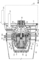
- the disclosed embodiments relate to a generator 100 ( FIG. 3 ) located in a tail cone 110 within an exit nozzle 120 of a gas turbine engine 130.
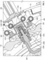
- the generator 100 includes first and second elastomeric moisture seals 140A, 140B ( FIG. 5 ), utilized to prevent moisture and water from reaching electrical contacts (or other components) within the generator 100.
- the gas turbine engine 130 has a turbine case 150 and a fan exit nozzle 120 at its aft end 160, which may be referred to as an exhaust assembly.
- the engine 130 has a generator assembly 170, with a generator 100 within a generator case 175, disposed in the fan exit nozzle 120.
- the generator is mounted, e.g., to the aft end 160 of the turbine case 150 or the forward end 120A of the and exit nozzle 120 via a mounting flange 177.
- An engine shaft 180 is operationally connected to a generator input shaft 190 via a dry drive coupler 195.
- An insulated tail cone 110 e.g., having internal and external insulation 112, 114, surrounds the generator assembly 170.
- Struts 200 extend between the tail cone 110 and the fan exit nozzle 120.
- Oil/air lines 202 and oil scavenge lines 204 extend through the struts 200.
- strut 200 having the scavenge lines 104 may be directed downwardly as it extends away from the generator 100, relative to gravity.
- the strut 200 having the oil/air lines 202 may be direct upwardly as it extends away from the generator 100.
- Feeder cables 222 extend through the struts 200 to the generator 100.
- FIG. 1 and 2 show the flow path of hot engine core air 211 at over twelve hundred degrees Fahrenheit and cool bypass air 213 at under three hundred degrees Fahrenheit flowing through the engine, inside and outside of the engine nozzle 120.
- This temperature difference between these flows, along with moisture carried by the bypass air 213, may result in moisture pooling around and within the struts 200.
- This moisture may travel down the feeder cables 222, e.g., by gravity, into the generator 100 and cause shorts, rust, and other resulting damage to the generator.
- the first and second elastomeric moisture seals 140A, 140B are utilized to prevent moisture and water from reaching electrical contacts within the generator 100.
- a rotor 220 in the case 175 of the generator 100 is coupled to the generator input shaft 190.
- the rotor 220 includes coil windings 230.
- a stator 240 surrounds the rotor 220.
- An exciter 250 is coupled to the input shaft 190 and the coil windings 230.
- the generator 100 also has a rotor balance assembly 252 and rotor bearings 254.
- FIG. 4 additional features of the generator assembly 170 are shown.
- the input shaft 190, struts 200, generator case 175, tail cone 110, exit nozzle 120, rotor 220, and windings 230, rotor balance assembly 252 and feeder cables 222 are shown.
- the generator case 175 defines case apertures 280. More specifically, the case apertures 280 are defined by aperture walls 290 extending through the generator case 175. The oil/air lines, scavenge lines and the feeder cables 222 are operationally coupled to the generator via the case apertures 280.
- the generator 100 includes output leads 300 that carry power generated by the generator 100 away from the stator 240.
- a first connector 310A is electrically connected to the output leads 300.
- the first connector 310A is a pin in one embodiment.
- An inner dielectric mount 320A surrounds the first connector310A.
- the inner dielectric mount 320A is disposed within the case aperture 280.
- a first oil seal 330A is between the inner dielectric mount 320A and the first connector310A.
- a second oil seal 330B is between the inner dielectric mount 320A and the aperture wall 290.
- the oil seals 330A, 330B are elastomers, and specifically rings or boots.
- An outer dielectric mount 320B is connected to the inner dielectric mount 320A within the case aperture 280 to define an overlapping portion 325 where the inner and outer dielectric mounts 320A, 320B overlap each other, with the inner mount 320A being exterior to the outer mount 320B at the overlapping portion 325.
- the outer dielectric mount 320B surrounds a second connector 310B.
- the second connector 310B is a female connector and may be a conductive bushing.
- the outer dielectric mount 320B is configured to connect the output leads to a feeder cable 222 via the first and second connectors 310A, 310B.
- the feeder cable 222 is supported within the strut 200 and extends between the generator 100 and the fan exit nozzle 120 ( FIG. 4 ).
- a harness bracket 370 secures the outer dielectric mount 320B to the generator case 175 at the case aperture 280.
- the first elastomeric moisture seal 140A is located between the inner and outer dielectric mounts 320A, 320B at the overlapping potion 325.
- the second elastomeric moisture seal 140B is located between the second connector 310B and the outer dielectric mount 320B.
- the first and second elastomeric moisture seals 140A, 140B are elastomeric rings or boots that prevent moisture from pasting therethrough.
- the generator 100 may have a plurality of the case apertures 280, circumferentially spaced apart from each other by increments of between thirty and ninety degrees.
- each of the case apertures 280 may include the first connector 310A electrically connected to the generator to draw power from it.
- the inner dielectric mount 320A may surrounds the first connector 310A.
- the second connector 310B may be contained in and surrounded by the outer dielectric mount 320B.
- the outer dielectric mount 320B may be configured to one of a plurality of feeder cables 222.
- Each of the inner and outer dielectric mounts 320A, 320B within one of the case apertures 280 may define a respective one of a plurality of dielectric mount pairs 400 that define an overlapping portion 325.
- At least one pair 410 of the dielectric mount pairs 400 is without the elastomeric moisture seals 140A, 140B.
- the at least one pair 410 of the dielectric mount pairs 400 without the elastomeric moisture seals 140 faces downwardly relative to gravity when the generator assembly 170 is operating.
- the struts 200 are angled downwardly and gravity draws moisture from the struts 200 and feeder cables 222 away from the generator 100 that would otherwise flow toward the generator 100.
- the moisture seals 140A, 140B are not needed for the downwardly facing mount pairs 410. However, including them is optional and does not depart from the teachings herein.
- the above configuration provides moisture seals 140A, 140B that prevent moisture from reaching the electrical connectors 310A, 310B and traveling into the generator 100, which could otherwise cause shorts, rust and other damage within the generator 100 located in the tail cone 110 of a gas turbine engine 130.
- the configuration prolongs the useful life of the generator 100 and enhances its reliability.
Landscapes
- Engineering & Computer Science (AREA)
- Power Engineering (AREA)
- Mechanical Engineering (AREA)
- General Engineering & Computer Science (AREA)
- Motor Or Generator Frames (AREA)
Abstract
A generator assembly having: a generator (100); a generator case (175) surrounding the generator and defining a case aperture (280); an output lead carrying power generated by the generator away from a stator of the generator; a first connector (3 10A) electrically connected to the output lead; an inner dielectric mount (320A) surrounding the first connector and disposed within the case aperture; an outer dielectric mount (320B) connected to the inner dielectric mount to define an overlapping portion (325) where the outer and inner dielectric mounts overlap each other; a second connector (310B) contained in and surrounded by the outer dielectric mount, the outer dielectric mount configured to connect the output leads to a feeder cable via the first and second connectors; a first elastomeric moisture seal (140A) located between the inner and outer dielectric mounts at the overlapping portion; and a second elastomeric moisture seal (140B) located between the second connector and an inner surface of the outer dielectric mount.
Description
- The disclosure is directed to a generator for a gas turbine engine and more specifically to a generator with moisture seals.
- A gas turbine engine includes a turbine surrounded by a turbine case and an exit nozzle. Ambient air may be directed into the exhaust region of an engine, via a bypass. This may provide weather-related water saturated conditions that make the exhaust region inhospitable to sensitive electronics.
- Disclosed is a generator assembly including: a generator; a generator case surrounding the generator and defining a case aperture; an output lead that carries power generated by the generator away from a stator of the generator; a first connector electrically connected to the output lead; an inner dielectric mount that surrounds the first connector and is disposed within the case aperture; an outer dielectric mount connected to the inner dielectric mount to define an overlapping portion where the outer and inner dielectric mounts overlap each other; a second connector contained in and surrounded by the outer dielectric mount, wherein the outer dielectric mount is configured to connect the output leads to a feeder cable via the first and second connectors; a first elastomeric moisture seal located between the inner and outer dielectric mounts at the overlapping portion; and a second elastomeric moisture seal located between the second connector and an inner surface of the outer dielectric mount.
- In embodiments, the first and second elastomeric moisture seals are elastomeric rings or boots.
- In embodiments, the first connector is a pin; and the second connector is a bushing.
- In embodiments, the inner and outer dielectric mounts are connected to each other with the case aperture.
- In embodiments, the generator case defines a plurality of the case apertures, circumferentially spaced apart from each other by increments of between thirty and ninety degrees, each of the case apertures includes: the first connector electrically connected to carry power from the generator; the inner dielectric mount that surrounds the first connector; the outer dielectric mount connected to the inner dielectric mount to define an overlapping portion where the outer and inner dielectric mounts overlap each other; the second connector contained in and surrounded by the outer dielectric mount, wherein the outer dielectric mount is configured to connect to one of a plurality of the feeder cables via the first and second connectors, wherein each of the inner and outer dielectric mounts within one of the case apertures defines a respective one of a plurality of dielectric mount pairs; and at least one of the dielectric mount pairs is without the elastomeric moisture seals.
- In embodiments, the at least one of the dielectric mount pairs without the elastomeric moisture seals is configured to face downwardly relative to gravity when the generator assembly is operating.
- In embodiments, the case aperture is defined by an aperture wall extending through the generator case; and the generator assembly further includes: a first oil seal between the inner dielectric mount and the first connector; and a second oil seal between the inner dielectric mount and the aperture wall.
- In embodiments, the oil seals are elastomers.
- In embodiments, the oil seals are elastomeric rings or boots.
- In embodiments, the generator has a forward portion and an aft portion, the forward portion defines the case aperture.
- In embodiments, the generator assembly further includes an insulated tail cone surrounding the generator; and a strut connected to the tail cone and extending way from the tail cone, wherein the feeder cable is supported within the strut.
- In embodiments, the generator assembly includes a generator input shaft; and a rotor coupled to the input shaft, the rotor including coil windings, wherein the stator surrounds the rotor and is fixed to the generator.
- In embodiments, the generator assembly further includes an exciter coupled to the input shaft and the coil windings.
- Further disclosed is an exhaust assembly of a gas turbine engine, including: a fan exit nozzle; and a generator assembly having one or more of the above disclosed aspects disposed in the fan exit nozzle, wherein the strut extends between the tail cone and the fan exit nozzle.
- Further disclosed is a gas turbine engine, including: a turbine case having an engine shaft and axial aft end; and an exhaust assembly having one or more of the above disclosed aspects connected to the aft end of the turbine case, wherein the fan exit nozzle and the generator assembly are connect to the aft end of the turbine case and the engine shaft is coupled to the generator input shaft.
- The present disclosure is illustrated by way of example and not limited in the accompanying figures in which like reference numerals indicate similar elements.
-
FIG. 1 is a partial sectional view of a generator according to an embodiment, where the generator is within an exit nozzle of a gas turbine engine, and the exit nozzle is connected to an aft end of a turbine case; -
FIG. 2 is a side view of the configuration shown inFIG. 1 , with additional aspects of the generator shown within the generator case; -
FIG. 3 is a perspective view of the generator within the generator case, the rest of the engine is not shown; -
FIG. 4 is a front view of the generator within the exit nozzle; and -
FIG. 5 is a detail identified inFIG. 4 of portion of the generator, showing the utilization of elastomeric moisture seals to prevent moisture on feeder cables, within and around struts, from reaching electrical contacts within the generator. - A detailed description of one or more embodiments of the disclosed apparatus and method are presented herein by way of exemplification and not limitation with reference to the Figures.
- The disclosed embodiments relate to a generator 100 (
FIG. 3 ) located in atail cone 110 within anexit nozzle 120 of agas turbine engine 130. Thegenerator 100 includes first and secondelastomeric moisture seals FIG. 5 ), utilized to prevent moisture and water from reaching electrical contacts (or other components) within thegenerator 100. - Turning to
FIGS. 1 and2 , thegas turbine engine 130 has aturbine case 150 and afan exit nozzle 120 at its aft end 160, which may be referred to as an exhaust assembly. Theengine 130 has agenerator assembly 170, with agenerator 100 within agenerator case 175, disposed in thefan exit nozzle 120. The generator is mounted, e.g., to the aft end 160 of theturbine case 150 or theforward end 120A of the andexit nozzle 120 via amounting flange 177. Anengine shaft 180 is operationally connected to agenerator input shaft 190 via adry drive coupler 195. An insulatedtail cone 110, e.g., having internal andexternal insulation generator assembly 170.Struts 200 extend between thetail cone 110 and thefan exit nozzle 120. Oil/air lines 202 and oil scavenge lines 204 extend through thestruts 200. In operation,strut 200 having the scavenge lines 104 may be directed downwardly as it extends away from thegenerator 100, relative to gravity. Thestrut 200 having the oil/air lines 202 may be direct upwardly as it extends away from thegenerator 100.Feeder cables 222 extend through thestruts 200 to thegenerator 100. -
FIG. 1 and2 show the flow path of hotengine core air 211 at over twelve hundred degrees Fahrenheit andcool bypass air 213 at under three hundred degrees Fahrenheit flowing through the engine, inside and outside of theengine nozzle 120. This temperature difference between these flows, along with moisture carried by thebypass air 213, may result in moisture pooling around and within thestruts 200. This moisture may travel down thefeeder cables 222, e.g., by gravity, into thegenerator 100 and cause shorts, rust, and other resulting damage to the generator. As indicated above and disclosed in greater detail below, the first and secondelastomeric moisture seals FIG. 5 ) are utilized to prevent moisture and water from reaching electrical contacts within thegenerator 100. - With reference to
FIGS. 2 and3 , arotor 220 in thecase 175 of thegenerator 100 is coupled to thegenerator input shaft 190. Therotor 220 includescoil windings 230. Astator 240 surrounds therotor 220. Anexciter 250 is coupled to theinput shaft 190 and thecoil windings 230. Thegenerator 100 also has arotor balance assembly 252 androtor bearings 254. - Turning to
FIG. 4 , additional features of thegenerator assembly 170 are shown. For reference, inFIG. 4 theinput shaft 190,struts 200,generator case 175,tail cone 110,exit nozzle 120,rotor 220, andwindings 230,rotor balance assembly 252 andfeeder cables 222 are shown. - As shown in
FIG. 5 , thegenerator case 175 definescase apertures 280. More specifically, thecase apertures 280 are defined byaperture walls 290 extending through thegenerator case 175. The oil/air lines, scavenge lines and thefeeder cables 222 are operationally coupled to the generator via thecase apertures 280. - The
generator 100 includes output leads 300 that carry power generated by thegenerator 100 away from thestator 240. Afirst connector 310A is electrically connected to the output leads 300. Thefirst connector 310A is a pin in one embodiment. An innerdielectric mount 320A surrounds the first connector310A. The innerdielectric mount 320A is disposed within thecase aperture 280. Afirst oil seal 330A is between the innerdielectric mount 320A and the first connector310A. Asecond oil seal 330B is between the innerdielectric mount 320A and theaperture wall 290. Theoil seals - An outer
dielectric mount 320B is connected to the innerdielectric mount 320A within thecase aperture 280 to define an overlappingportion 325 where the inner and outerdielectric mounts inner mount 320A being exterior to theouter mount 320B at the overlappingportion 325. The outerdielectric mount 320B surrounds asecond connector 310B. Thesecond connector 310B is a female connector and may be a conductive bushing. The outerdielectric mount 320B is configured to connect the output leads to afeeder cable 222 via the first andsecond connectors feeder cable 222 is supported within thestrut 200 and extends between thegenerator 100 and the fan exit nozzle 120 (FIG. 4 ). Aharness bracket 370 secures the outerdielectric mount 320B to thegenerator case 175 at thecase aperture 280. - The first
elastomeric moisture seal 140A is located between the inner and outer dielectric mounts 320A, 320B at the overlappingpotion 325. The secondelastomeric moisture seal 140B is located between thesecond connector 310B and the outerdielectric mount 320B. The first and second elastomeric moisture seals 140A, 140B are elastomeric rings or boots that prevent moisture from pasting therethrough. - As shown in
FIG. 4 , thegenerator 100 may have a plurality of the case apertures 280, circumferentially spaced apart from each other by increments of between thirty and ninety degrees. As with the configuration ofFIG. 5 , each of the case apertures 280 may include thefirst connector 310A electrically connected to the generator to draw power from it. The innerdielectric mount 320A may surrounds thefirst connector 310A. Thesecond connector 310B may be contained in and surrounded by the outerdielectric mount 320B. The outerdielectric mount 320B may be configured to one of a plurality offeeder cables 222. Each of the inner and outer dielectric mounts 320A, 320B within one of the case apertures 280 may define a respective one of a plurality of dielectric mount pairs 400 that define an overlappingportion 325. - According to an embodiment, at least one
pair 410 of the dielectric mount pairs 400, is without the elastomeric moisture seals 140A, 140B. Specifically, the at least onepair 410 of the dielectric mount pairs 400 without the elastomeric moisture seals 140 faces downwardly relative to gravity when thegenerator assembly 170 is operating. For these dielectric mount pairs 410, thestruts 200 are angled downwardly and gravity draws moisture from thestruts 200 andfeeder cables 222 away from thegenerator 100 that would otherwise flow toward thegenerator 100. Thus, the moisture seals 140A, 140B are not needed for the downwardly facing mount pairs 410. However, including them is optional and does not depart from the teachings herein. - The above configuration provides moisture seals 140A, 140B that prevent moisture from reaching the
electrical connectors generator 100, which could otherwise cause shorts, rust and other damage within thegenerator 100 located in thetail cone 110 of agas turbine engine 130. The configuration prolongs the useful life of thegenerator 100 and enhances its reliability. - The terminology used herein is for the purpose of describing particular embodiments only and is not intended to be limiting of the present disclosure. As used herein, the singular forms "a", "an" and "the" are intended to include the plural forms as well, unless the context clearly indicates otherwise. It will be further understood that the terms "comprises" and/or "comprising," when used in this specification, specify the presence of stated features, integers, steps, operations, elements, and/or components, but do not preclude the presence or addition of one or more other features, integers, steps, operations, element components, and/or groups thereof.
- Those of skill in the art will appreciate that various example embodiments are shown and described herein, each having certain features in the particular embodiments, but the present disclosure is not thus limited. Rather, the scope of the invention is as defined by the appended claims.
Claims (15)
- A generator assembly comprising:a generator (100);a generator case (175) surrounding the generator and defining a case aperture (280);an output lead that carries power generated by the generator away from a stator of the generator;a first connector (3 10A) electrically connected to the output lead;an inner dielectric mount (320A) that surrounds the first connector and is disposed within the case aperture;an outer dielectric mount (320B) connected to the inner dielectric mount to define an overlapping portion (325) where the outer and inner dielectric mounts overlap each other;a second connector (310B) contained in and surrounded by the outer dielectric mount, wherein the outer dielectric mount is configured to connect the output leads to a feeder cable via the first and second connectors;a first elastomeric moisture seal (140A) located between the inner and outer dielectric mounts at the overlapping portion; anda second elastomeric moisture seal (140B) located between the second connector and an inner surface of the outer dielectric mount.
- The generator assembly of claim 1, wherein:
the first and second elastomeric moisture seals are elastomeric rings or boots. - The generator assembly of claim 2, wherein:the first connector is a pin; andthe second connector is a bushing.
- The generator assembly of claim 3, wherein:
the inner and outer dielectric mounts are connected to each other with the case aperture. - The generator assembly of claim 4, wherein:
the generator case defines a plurality of the case apertures, circumferentially spaced apart from each other by increments of between thirty and ninety degrees, each of the case apertures includes:the first connector electrically connected to carry power from the generator;the inner dielectric mount that surrounds the first connector;the outer dielectric mount connected to the inner dielectric mount to define an overlapping portion where the outer and inner dielectric mounts overlap each other;the second connector contained in and surrounded by the outer dielectric mount, wherein the outer dielectric mount is configured to connect to one of a plurality of the feeder cables via the first and second connectors,wherein each of the inner and outer dielectric mounts within one of the case apertures defines a respective one of a plurality of dielectric mount pairs; andat least one of the dielectric mount pairs is without the elastomeric moisture seals. - The generator assembly of claim 5, wherein:
the at least one of the dielectric mount pairs without the elastomeric moisture seals is configured to face downwardly relative to gravity when the generator assembly is operating. - The generator assembly of claim 4, wherein:the case aperture is defined by an aperture wall extending through the generator case; andthe generator assembly further comprises:a first oil seal (320A) between the inner dielectric mount and the first connector; anda second oil seal (320B) between the inner dielectric mount and the aperture wall.
- The generator assembly of claim 7, wherein:
the oil seals are elastomers. - The generator assembly of claim 8, wherein:
the oil seals are elastomeric rings or boots. - The generator assembly of claim 9, wherein:
the generator has a forward portion and an aft portion, the forward portion defines the case aperture. - The generator assembly of claim 10, further comprising:an insulated tail cone (110) surrounding the generator; anda strut (200) connected to the tail cone and extending way from the tail cone, wherein the feeder cable is supported within the strut.
- The generator assembly of claim 11, further comprising:a generator input shaft (190); anda rotor (220) coupled to the input shaft, the rotor including coil windings, wherein the stator surrounds the rotor and is fixed to the generator.
- The generator assembly of claim 12, further comprising:
an exciter (250) coupled to the input shaft and the coil windings. - An exhaust assembly of a gas turbine engine, comprising:a fan exit nozzle (120); andthe generator assembly of claim 13 disposed in the fan exit nozzle,wherein the strut extends between the tail cone and the fan exit nozzle.
- A gas turbine engine, comprising:a turbine case (150) having an engine shaft and axial aft end; andthe exhaust assembly of claim 14 connected to the aft end of the turbine case,wherein the fan exit nozzle and the generator assembly are connect to the aft end of the turbine case and the engine shaft is coupled to the generator input shaft.
Applications Claiming Priority (1)
| Application Number | Priority Date | Filing Date | Title |
|---|---|---|---|
| US18/165,606 US12424904B2 (en) | 2023-02-07 | 2023-02-07 | Generator with moisture seals |
Publications (1)
| Publication Number | Publication Date |
|---|---|
| EP4415233A1 true EP4415233A1 (en) | 2024-08-14 |
Family
ID=89854570
Family Applications (1)
| Application Number | Title | Priority Date | Filing Date |
|---|---|---|---|
| EP24156344.4A Pending EP4415233A1 (en) | 2023-02-07 | 2024-02-07 | Generator with moisture seals |
Country Status (2)
| Country | Link |
|---|---|
| US (1) | US12424904B2 (en) |
| EP (1) | EP4415233A1 (en) |
Citations (3)
| Publication number | Priority date | Publication date | Assignee | Title |
|---|---|---|---|---|
| US7071588B1 (en) * | 2004-05-20 | 2006-07-04 | Yeomans Chicago Corporation | Pump motor penetration assembly |
| EP1811132A1 (en) * | 2006-01-24 | 2007-07-25 | Snecma | Turbomachine with integrated generator-starter |
| EP3879074A1 (en) * | 2020-03-09 | 2021-09-15 | Hamilton Sundstrand Corporation | Tail cone assembly for a gas turbine engine and mounted generator |
Family Cites Families (2)
| Publication number | Priority date | Publication date | Assignee | Title |
|---|---|---|---|---|
| US4712029A (en) * | 1986-12-22 | 1987-12-08 | Sundstrand Corporation | Generator high temperature electrical lead assembly |
| US6628024B1 (en) * | 2002-07-30 | 2003-09-30 | Honeywell International, Inc. | Hermetically sealed feed-through assembly for gas turbine engine starter generators and related methods |
-
2023
- 2023-02-07 US US18/165,606 patent/US12424904B2/en active Active
-
2024
- 2024-02-07 EP EP24156344.4A patent/EP4415233A1/en active Pending
Patent Citations (3)
| Publication number | Priority date | Publication date | Assignee | Title |
|---|---|---|---|---|
| US7071588B1 (en) * | 2004-05-20 | 2006-07-04 | Yeomans Chicago Corporation | Pump motor penetration assembly |
| EP1811132A1 (en) * | 2006-01-24 | 2007-07-25 | Snecma | Turbomachine with integrated generator-starter |
| EP3879074A1 (en) * | 2020-03-09 | 2021-09-15 | Hamilton Sundstrand Corporation | Tail cone assembly for a gas turbine engine and mounted generator |
Also Published As
| Publication number | Publication date |
|---|---|
| US20240266916A1 (en) | 2024-08-08 |
| US12424904B2 (en) | 2025-09-23 |
Similar Documents
| Publication | Publication Date | Title |
|---|---|---|
| US7855483B2 (en) | Turbomachine with integral generator/starter | |
| US9303523B2 (en) | Sensor communication system and machine having the same | |
| US6897581B2 (en) | High speed generator with the main rotor housed inside the shaft | |
| RU2445481C2 (en) | Distributed architecture of gas turbine starter-generator | |
| US8899945B2 (en) | Centrifugal compressor unit | |
| US11125103B2 (en) | Gas turbine generators | |
| KR20140124422A (en) | Fluid cooled electrically-assisted turbocharger | |
| JP7741777B2 (en) | Rotating electric machine system and hybrid power system equipped with the same | |
| US12424904B2 (en) | Generator with moisture seals | |
| US20160340053A1 (en) | Turbomachine comprising a ventilation system | |
| EP3223407A1 (en) | Ac generator for vehicles | |
| EP3223404A1 (en) | Alternating-current generator for vehicle | |
| EP4183996A1 (en) | Cooling system for tail cone mounted generator | |
| US9320181B1 (en) | System and method for dissipating thermal energy away from electronic components in a rotatable shaft | |
| EP2747255A1 (en) | Rotor for an electric machine | |
| CN114761668A (en) | Electrical module for an aircraft turbomachine | |
| US6501207B2 (en) | Rotor for a vehicular A. C. generator | |
| US20160341205A1 (en) | Assembly for an engine which can define a blade break-off test device | |
| US12603538B2 (en) | Rotating electric machine system | |
| EP3223405A1 (en) | Ac generator for vehicles | |
| US9863269B2 (en) | System for packaging electronic components in a rotatable shaft | |
| CN114929994A (en) | Turbo-generator for an aircraft comprising an improved oil system | |
| US12483083B2 (en) | Rotating electric machine system and combined power system equipped therewith | |
| US10541581B2 (en) | Alternator having an external ignition protection system | |
| US20240072486A1 (en) | Electrical connector comprising two sleeves defining a closed equipotential cavity around a contact zone |
Legal Events
| Date | Code | Title | Description |
|---|---|---|---|
| PUAI | Public reference made under article 153(3) epc to a published international application that has entered the european phase |
Free format text: ORIGINAL CODE: 0009012 |
|
| STAA | Information on the status of an ep patent application or granted ep patent |
Free format text: STATUS: THE APPLICATION HAS BEEN PUBLISHED |
|
| AK | Designated contracting states |
Kind code of ref document: A1 Designated state(s): AL AT BE BG CH CY CZ DE DK EE ES FI FR GB GR HR HU IE IS IT LI LT LU LV MC ME MK MT NL NO PL PT RO RS SE SI SK SM TR |
|
| STAA | Information on the status of an ep patent application or granted ep patent |
Free format text: STATUS: REQUEST FOR EXAMINATION WAS MADE |
|
| 17P | Request for examination filed |
Effective date: 20250213 |
|
| STAA | Information on the status of an ep patent application or granted ep patent |
Free format text: STATUS: EXAMINATION IS IN PROGRESS |