EP4415190A1 - Power distribution unit with unique busbar mounting design - Google Patents
Power distribution unit with unique busbar mounting design Download PDFInfo
- Publication number
- EP4415190A1 EP4415190A1 EP24156879.9A EP24156879A EP4415190A1 EP 4415190 A1 EP4415190 A1 EP 4415190A1 EP 24156879 A EP24156879 A EP 24156879A EP 4415190 A1 EP4415190 A1 EP 4415190A1
- Authority
- EP
- European Patent Office
- Prior art keywords
- insulator
- central
- busbar
- standoff
- lateral
- Prior art date
- Legal status (The legal status is an assumption and is not a legal conclusion. Google has not performed a legal analysis and makes no representation as to the accuracy of the status listed.)
- Pending
Links
Images



Classifications
-
- H—ELECTRICITY
- H02—GENERATION; CONVERSION OR DISTRIBUTION OF ELECTRIC POWER
- H02B—BOARDS, SUBSTATIONS OR SWITCHING ARRANGEMENTS FOR THE SUPPLY OR DISTRIBUTION OF ELECTRIC POWER
- H02B1/00—Frameworks, boards, panels, desks, casings; Details of substations or switching arrangements
- H02B1/20—Bus-bar or other wiring layouts, e.g. in cubicles, in switchyards
-
- H—ELECTRICITY
- H02—GENERATION; CONVERSION OR DISTRIBUTION OF ELECTRIC POWER
- H02B—BOARDS, SUBSTATIONS OR SWITCHING ARRANGEMENTS FOR THE SUPPLY OR DISTRIBUTION OF ELECTRIC POWER
- H02B1/00—Frameworks, boards, panels, desks, casings; Details of substations or switching arrangements
- H02B1/26—Casings; Parts thereof or accessories therefor
- H02B1/30—Cabinet-type casings; Parts thereof or accessories therefor
- H02B1/32—Mounting of devices therein
-
- H—ELECTRICITY
- H02—GENERATION; CONVERSION OR DISTRIBUTION OF ELECTRIC POWER
- H02G—INSTALLATION OF ELECTRIC CABLES OR LINES, OR OF COMBINED OPTICAL AND ELECTRIC CABLES OR LINES
- H02G5/00—Installations of bus-bars
- H02G5/02—Open installations
-
- H—ELECTRICITY
- H02—GENERATION; CONVERSION OR DISTRIBUTION OF ELECTRIC POWER
- H02G—INSTALLATION OF ELECTRIC CABLES OR LINES, OR OF COMBINED OPTICAL AND ELECTRIC CABLES OR LINES
- H02G5/00—Installations of bus-bars
- H02G5/02—Open installations
- H02G5/025—Supporting structures
Definitions
- Apparatuses and methods consistent with example embodiments relate to electrical/electronics equipment units, and more particularly to an electrical/electronics power distribution unit with a unique busbar mounting design.
- Power distribution equipment units are typically used to receive output power from a power transformer cabinet and to distribute the received power via a plurality of output distribution power cables to a plurality of different power output panelboards.
- Such power distribution units (PDUs) with built-in monitoring and controls require printed circuit boards, power supplies, and other electronic modules which are installed in the unit in secure and protected location(s).
- Field input power cables are required to provide energy to the PDU.
- These input cables may be in a size range of about 1/0AWG to 600Kcmil size range, with compression/mechanical lugs. Thus, these lugs and cables are large and take up a significant amount of space within the PDU.
- the lugs of these input cables and the busbar they connect to are live parts with hazardous voltage on them.
- a center busbar is elevated or "pushed-out" away from the left and right busbars. This provides spacing by moving the center busbar forward in space and thus away from the other two phases. Spacing between the outer busbars may be maintained.
- this solution requires sufficient depth within the PDU. It is desirable to design an arrangement in which the depth required for the breakers, busbars, and input cables is significantly reduced.
- Example embodiments may address at least the above problems and/or disadvantages and other disadvantages not described above. Also, example embodiments are not required to overcome the disadvantages described above, and may not overcome any of the problems described above.
- a power distribution unit comprises: a primary bracket comprising a hole therethrough; a secondary bracket mounted to a rear of the primary bracket, around the hole; a first central standoff insulator mounted to a front of the secondary bracket and extending through the hole; a second central standoff insulator mounted to a front of the first central standoff insulator; a central busbar mounted to a front of the second central standoff insulator; an insulator comprising: a rear portion mounted between the first central standoff insulator and the second central standoff insulator, a first side portion extending frontward past a first side of the central busbar, and a second side portion extending frontward past a second side of the central busbar.
- the power distribution unit may further comprise: a first lateral standoff insulator mounted to a front of the primary bracket to a first side of the first central standoff insulator; a second lateral standoff insulator mounted to the front of the primary bracket to a second side of the first central standoff insulator; a first lateral busbar mounted to a front of the first lateral standoff insulator; and a second lateral busbar mounted to a front of the second lateral standoff insulator.
- the first side portion of the insulator may extend between the second central standoff insulator and the central busbar on one side thereof and the first lateral standoff insulator and the first lateral busbar on an opposite side thereof; and the second side portion of the insulator may extend between the central standoff insulator and the central busbar on one side thereof and the second lateral standoff insulator and the second lateral busbar on an opposite side thereof.
- the insulator may comprise polypropylene.
- the insulator may have a substantially U-shaped cross-section.
- the primary bracket may comprise sheet metal.
- the secondary bracket may comprise sheet metal.
- the hole in the primary bracket may be substantially circular.
- an equipment cabinet may comprise: a cabinet frame; a door connected to the cabinet frame, the door comprising a power distribution unit comprising: a primary bracket comprising a hole therethrough; a secondary bracket mounted to a rear of the primary bracket around the hole; a first central standoff insulator mounted to a front of the secondary bracket and extending through the hole; a second central standoff insulator mounted to a front of the first central standoff insulator; a central busbar mounted to a front of the second central standoff insulator; an insulator comprising: a rear portion mounted between the first central standoff insulator and the second central standoff insulator, a first side portion extending frontward past a first side of the central busbar, and a second side portion extending frontward past a second side of the central busbar.
- a method of assembling a power distribution unit may comprise: forming a hole in a primary bracket; mounting a secondary bracket to a rear of the primary bracket, around the hole; mounting a first central standoff insulator to a front of the secondary bracket such that the first central standoff insulator extends through the hole; mounting a second central standoff insulator to a front of the first central standoff insulator; mounting a central busbar to a front of the second central standoff insulator; and mounting an insulator by mounting a rear portion of the insulator between the first central standoff insulator and the second central standoff insulator, extending a first side portion of the insulator past a first side of the central busbar, and extending a second side portion of the insulator past a second side of the central busbar.
- the term "and/or" includes any and all combinations of one or more of the associated listed items. Expressions such as “at least one of,” when preceding a list of elements, modify the entire list of elements and do not modify the individual elements of the list.
- FIG. 1 an example electrical/electronics equipment cabinet 10 (hereinafter simply “cabinet 10") is shown.
- the cabinet 10 includes customer cable input and output areas 21 and 22 at the top and bottom of the cabinet 10, respectively.
- the cabinet 10 also includes a control area 12, a main input circuit breaker 14, output circuit breakers 15, an output panel board 23, current transformers/sensors 20, a customer cable routing area 19, a control and sense wiring routing trough 18, remote communication cards 17, and a human machine interface 16.
- One or more example embodiments described herein provide a busbar and spacing design in which a primary busbar mounting bracket has a hole added behind the center busbar location. A separate sheet metal bracket is secured, behind the hole, to the primary busbar mounting bracket, functioning as a mounting location for the center busbar and electrical standoffs. Accordingly, one or more example embodiments enable a reduction in the total depth of the breaker and busbar solution which still providing sufficient mounting strength and air gaps.
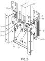
- FIG. 2 is a perspective view of a mounting design according to an example embodiment
- FIG. 3 is a top view of the mounting design of FIG. 2
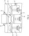
- FIG. 4 is a top, perspective view of a portion of the mounting design of FIG. 2 .
- a hole 110 ( see FIG. 4 ) is provided in the sheet metal of the primary busbar mounting bracket 105 that mounts the breaker to the PDU, behind a location of the center busbar 108 ( see FIGs. 3 and 4 ), and an additional sheet metal bracket 106 is secured to the primary busbar mounting bracket 105, behind the hole 110, using a lug 109.
- the shape of the primary mounting bracket 105 including opposing edges 105a, which extend, normal to the central region of the primary bracket 105, towards a rear of the unit, enable the additional bracket 106 to be secured to the primary bracket 105 around the hole 110.
- the additional bracket 106 may have a perimeter larger than the perimeter of the hole 110, enabling the additional bracket 106 to be mounted to the primary bracket 105 around the hole 110.
- Center busbar electrical standoff insulators 104 are mounted, via the lug 109, to the front of the additional bracket 106; and the center busbar 108 is mounted on the front of the center standoff insulators 104.
- Electrical insulation 101 made of, for example, polypropylene, Nomex ® , or another similar material, is mounted between adjacent ones the stacked central standoff insulators 104 and partially encloses the center busbar 108.
- the electrical insulation 101 may have a substantially U-shaped cross-section, as viewed from above, which extends between the two central standoff insulators 104 and has sides that extend forward, between the center busbar 108 and the adjacent left and right busbars 107, respectively. This insulation 101, thus, provides electrical isolation between the center busbar 108 and the left and right busbars 107.
- the two central standoff insulators 104 are stacked behind the central busbar 108.
- the hole 110 in the primary busbar mounting bracket 105 enables one of the central standoff insulators 104 to extend through the primary mounting bracket 105 and rest against the front of the additional sheet metal bracket 106.
- the hole in 110 in the primary busbar mounting bracket 105 may be round or any other shape which enables a central standoff insulator 104 to extend therethrough to be mounted against the front of the additional sheet metal bracket 106.
- the insulation 101 extends between the two central standoff insulators 104, and extends to insulate the central busbar 108 from the left and right busbars 107, as shown in FIGs. 3 and 4 .
- FIG. 5 generally illustrates a method 500, according to the principles of the present disclosure.
- the method 500 forms a hole in a primary bracket.
- the method 500 mounts a secondary bracket to a rear of the primary bracket, around the hole.
- the method 500 mounts a first central standoff insulator to a front of the secondary bracket such that the first central standoff insulator extends through the hole.
- the method 500 mounts a second central standoff insulator to a front of the first central standoff insulator.
- the method 500 mounts a central busbar to a front of the second central standoff insulator.
- the method 500 mounts an insulator by mounting a rear portion of the insulator between the first central standoff insulator and the second central standoff insulator, extending a first side portion of the insulator past a first side of the central busbar, and extending a second side portion of the insulator past a second side of the central busbar.
- a power distribution unit includes a primary bracket comprising a hole therethrough; a secondary bracket mounted to a rear of the primary bracket, around the hole; a first central standoff insulator mounted to a front of the secondary bracket and extending through the hole; a second central standoff insulator mounted to a front of the first central standoff insulator; a central busbar mounted to a front of the second central standoff insulator; an insulator comprising: a rear portion mounted between the first central standoff insulator and the second central standoff insulator, a first side portion extending frontward past a first side of the central busbar, and a second side portion extending frontward past a second side of the central busbar.
- the power distribution also includes a first lateral standoff insulator mounted to a front of the primary bracket to a first side of the first central standoff insulator; a second lateral standoff insulator mounted to the front of the primary bracket to a second side of the first central standoff insulator; a first lateral busbar mounted to a front of the first lateral standoff insulator; and a second lateral busbar mounted to a front of the second lateral standoff insulator.
- the first side portion of the insulator extends between the second central standoff insulator and the central busbar on one side thereof and the first lateral standoff insulator and the first lateral busbar on an opposite side thereof; and the second side portion of the insulator extends between the central standoff insulator and the central busbar on one side thereof and the second lateral standoff insulator and the second lateral busbar on an opposite side thereof.
- the insulator comprises polypropylene.
- the insulator has a substantially U-shaped cross-section.
- the primary bracket comprises sheet metal.
- the secondary bracket comprises sheet metal.
- the hole in the primary bracket is substantially circular.
- an equipment cabinet includes: a cabinet frame; a door connected to the cabinet frame, the door comprising a power distribution unit comprising: a primary bracket comprising a hole therethrough; a secondary bracket mounted to a rear of the primary bracket around the hole; a first central standoff insulator mounted to a front of the secondary bracket and extending through the hole; a second central standoff insulator mounted to a front of the first central standoff insulator; a central busbar mounted to a front of the second central standoff insulator; an insulator comprising: a rear portion mounted between the first central standoff insulator and the second central standoff insulator, a first side portion extending frontward past a first side of the central busbar, and a second side portion extending frontward past a second side of the central busbar.
- the power distribution unit further includes: a first lateral standoff insulator mounted to a front of the primary bracket to a first side of the first central standoff insulator; a second lateral standoff insulator mounted to the front of the primary bracket to a second side of the first central standoff insulator; a first lateral busbar mounted to a front of the first lateral standoff insulator; and a second lateral busbar mounted to a front of the second lateral standoff insulator.
- the first side portion of the insulator extends between the second central standoff insulator and the central busbar on one side thereof and the first lateral standoff insulator and the first lateral busbar on an opposite side thereof; and the second side portion of the insulator extends between the central standoff insulator and the central busbar on one side thereof and the second lateral standoff insulator and the second lateral busbar on an opposite side thereof.
- the insulator comprises polypropylene.
- the insulator has a substantially U-shaped cross-section.
- the primary bracket comprises sheet metal.
- the secondary bracket comprises sheet metal.
- the hole in the primary bracket is substantially circular.
- a method of assembling a power distribution unit includes forming a hole in a primary bracket; mounting a secondary bracket to a rear of the primary bracket, around the hole; mounting a first central standoff insulator to a front of the secondary bracket such that the first central standoff insulator extends through the hole; mounting a second central standoff insulator to a front of the first central standoff insulator; mounting a central busbar to a front of the second central standoff insulator; and mounting an insulator by mounting a rear portion of the insulator between the first central standoff insulator and the second central standoff insulator, extending a first side portion of the insulator past a first side of the central busbar, and extending a second side portion of the insulator past a second side of the central busbar.
- the method also includes: mounting a first lateral standoff insulator to a front of the primary bracket to a first side of the first central standoff insulator; mounting a second lateral standoff insulator to a front of the primary bracket to a second side of the first central standoff insulator; mounting a first lateral busbar to a front of the first lateral standoff insulator; and mounting a second lateral busbar to a front of the second lateral standoff insulator.
- the first side portion of the insulator extends between the second central standoff insulator and the central busbar on one side thereof and the first lateral standoff insulator and the first lateral busbar on an opposite side thereof; and the second side portion of the insulator extends between the central standoff insulator and the central busbar on one side thereof and the second lateral standoff insulator and the second lateral busbar on an opposite side thereof.
- the insulator comprises polypropylene.
Landscapes
- Engineering & Computer Science (AREA)
- Power Engineering (AREA)
- Patch Boards (AREA)
Abstract
A power distribution unit of an equipment cabinet includes a primary bracket, and a secondary bracket. A first central standoff insulator is mounted to a front of the secondary bracket and extends through a hole in the primary bracket. A second standoff insulator is mounted to a front of the first central standoff insulator, and a central busbar is mounted to a front of the second central standoff insulator. An insulator comprises a rear portion mounted between the first central standoff insulator and the second central standoff insulator and has a first side portion extending frontward past a first side of the central busbar and a second side portion extending frontward past a second side of the central busbar. First and second lateral standoff insulators and first and second lateral busbars, respectively mounted to the first and second lateral standoff insulators, maybe mounted to the primary bracket.
Description
- This U.S. Utility Patent Application claims priority to
US Provisional Patent Application Serial No. 63/444,784, filed February 10, 2023 - Apparatuses and methods consistent with example embodiments relate to electrical/electronics equipment units, and more particularly to an electrical/electronics power distribution unit with a unique busbar mounting design.
- Power distribution equipment units are typically used to receive output power from a power transformer cabinet and to distribute the received power via a plurality of output distribution power cables to a plurality of different power output panelboards. Such power distribution units (PDUs) with built-in monitoring and controls require printed circuit boards, power supplies, and other electronic modules which are installed in the unit in secure and protected location(s). Field input power cables are required to provide energy to the PDU. These input cables may be in a size range of about 1/0AWG to 600Kcmil size range, with compression/mechanical lugs. Thus, these lugs and cables are large and take up a significant amount of space within the PDU. There may be three to five conductors per input, including, for example, phase A/1, B/2, C/3, neutral, and ground conductors. The lugs of these input cables and the busbar they connect to are live parts with hazardous voltage on them.
- Industry standards, such as those of UL, NEC, IEC, and others, require that specific spacings or airgaps are maintained between and among hazardous voltage components. The spacing/airgap varies, depending on the standard in use. Thus, designing the arrangement of these very large, often oversized cables all feeding into a single breaker in the PDU is a significant engineering challenge as they must be spaced out as they land on the breaker in order to maintain electrical separation.
- In some related art arrangements, a center busbar is elevated or "pushed-out" away from the left and right busbars. This provides spacing by moving the center busbar forward in space and thus away from the other two phases. Spacing between the outer busbars may be maintained. However, this solution requires sufficient depth within the PDU. It is desirable to design an arrangement in which the depth required for the breakers, busbars, and input cables is significantly reduced.
- Example embodiments may address at least the above problems and/or disadvantages and other disadvantages not described above. Also, example embodiments are not required to overcome the disadvantages described above, and may not overcome any of the problems described above.
- According to an aspect of an example embodiment, a power distribution unit comprises: a primary bracket comprising a hole therethrough; a secondary bracket mounted to a rear of the primary bracket, around the hole; a first central standoff insulator mounted to a front of the secondary bracket and extending through the hole; a second central standoff insulator mounted to a front of the first central standoff insulator; a central busbar mounted to a front of the second central standoff insulator; an insulator comprising: a rear portion mounted between the first central standoff insulator and the second central standoff insulator, a first side portion extending frontward past a first side of the central busbar, and a second side portion extending frontward past a second side of the central busbar.
- The power distribution unit may further comprise: a first lateral standoff insulator mounted to a front of the primary bracket to a first side of the first central standoff insulator; a second lateral standoff insulator mounted to the front of the primary bracket to a second side of the first central standoff insulator; a first lateral busbar mounted to a front of the first lateral standoff insulator; and a second lateral busbar mounted to a front of the second lateral standoff insulator.
- The first side portion of the insulator may extend between the second central standoff insulator and the central busbar on one side thereof and the first lateral standoff insulator and the first lateral busbar on an opposite side thereof; and the second side portion of the insulator may extend between the central standoff insulator and the central busbar on one side thereof and the second lateral standoff insulator and the second lateral busbar on an opposite side thereof.
- The insulator may comprise polypropylene.
- The insulator may have a substantially U-shaped cross-section.
- The primary bracket may comprise sheet metal.
- The secondary bracket may comprise sheet metal.
- The hole in the primary bracket may be substantially circular.
- According to an aspect of another example embodiment, an equipment cabinet may comprise: a cabinet frame; a door connected to the cabinet frame, the door comprising a power distribution unit comprising: a primary bracket comprising a hole therethrough; a secondary bracket mounted to a rear of the primary bracket around the hole; a first central standoff insulator mounted to a front of the secondary bracket and extending through the hole; a second central standoff insulator mounted to a front of the first central standoff insulator; a central busbar mounted to a front of the second central standoff insulator; an insulator comprising: a rear portion mounted between the first central standoff insulator and the second central standoff insulator, a first side portion extending frontward past a first side of the central busbar, and a second side portion extending frontward past a second side of the central busbar.
- According to an aspect of another example embodiment, a method of assembling a power distribution unit may comprise: forming a hole in a primary bracket; mounting a secondary bracket to a rear of the primary bracket, around the hole; mounting a first central standoff insulator to a front of the secondary bracket such that the first central standoff insulator extends through the hole; mounting a second central standoff insulator to a front of the first central standoff insulator; mounting a central busbar to a front of the second central standoff insulator; and mounting an insulator by mounting a rear portion of the insulator between the first central standoff insulator and the second central standoff insulator, extending a first side portion of the insulator past a first side of the central busbar, and extending a second side portion of the insulator past a second side of the central busbar.
- The above and/or other aspects will become apparent and more readily appreciated from the following description of example embodiments, taken in conjunction with the accompanying drawings, in which:
-
FIG. 1 illustrates an equipment cabinet according to an example embodiment; -
FIG. 2 is a perspective view of a mounting design of a power distribution unit according to an example embodiment; -
FIG. 3 is a top view of the mounting design ofFIG. 2 ; -
FIG. 4 is a top, perspective view of a portion of the mounting design ofFIG. 2 ; and -
FIG. 5 is a method according to the principles of the present disclosure. - Reference will now be made in detail to example embodiments which are illustrated in the accompanying drawings, wherein like reference numerals refer to like elements throughout. In this regard, the example embodiments may have different forms and may not be construed as being limited to the descriptions set forth herein.
- It will be understood that the terms "include," "including", "comprise, and/or "comprising," when used in this specification, specify the presence of stated features, integers, steps, operations, elements, and/or components, but do not preclude the presence or addition of one or more other features, integers, steps, operations, elements, components, and/or groups thereof.
- It will be further understood that, although the terms "first," "second," "third," etc., may be used herein to describe various elements, components, regions, layers and/or sections, these elements, components, regions, layers and/or sections may not be limited by these terms. These terms are only used to distinguish one element, component, region, layer or section from another element, component, region, layer or section.
- As used herein, the term "and/or" includes any and all combinations of one or more of the associated listed items. Expressions such as "at least one of," when preceding a list of elements, modify the entire list of elements and do not modify the individual elements of the list.
- Various terms are used to refer to particular system components. Different companies may refer to a component by different names - this document does not intend to distinguish between components that differ in name but not function.
- Matters of these example embodiments that are obvious to those of ordinary skill in the technical field to which these example embodiments pertain may not be described herein in detail.
- Referring to
FIG. 1 , an example electrical/electronics equipment cabinet 10 (hereinafter simply "cabinet 10") is shown. Thecabinet 10 includes customer cable input andoutput areas cabinet 10, respectively. Thecabinet 10 also includes acontrol area 12, a maininput circuit breaker 14,output circuit breakers 15, anoutput panel board 23, current transformers/sensors 20, a customercable routing area 19, a control and sensewiring routing trough 18,remote communication cards 17, and ahuman machine interface 16. - One or more example embodiments described herein provide a busbar and spacing design in which a primary busbar mounting bracket has a hole added behind the center busbar location. A separate sheet metal bracket is secured, behind the hole, to the primary busbar mounting bracket, functioning as a mounting location for the center busbar and electrical standoffs. Accordingly, one or more example embodiments enable a reduction in the total depth of the breaker and busbar solution which still providing sufficient mounting strength and air gaps.
-
FIG. 2 is a perspective view of a mounting design according to an example embodiment;FIG. 3 is a top view of the mounting design ofFIG. 2 ; andFIG. 4 is a top, perspective view of a portion of the mounting design ofFIG. 2 . A hole 110 (seeFIG. 4 ) is provided in the sheet metal of the primarybusbar mounting bracket 105 that mounts the breaker to the PDU, behind a location of the center busbar 108 (seeFIGs. 3 and4 ), and an additionalsheet metal bracket 106 is secured to the primarybusbar mounting bracket 105, behind the hole 110, using alug 109. The shape of theprimary mounting bracket 105, includingopposing edges 105a, which extend, normal to the central region of theprimary bracket 105, towards a rear of the unit, enable theadditional bracket 106 to be secured to theprimary bracket 105 around the hole 110. Alternately, or in a case in which theprimary bracket 105 is substantially planar without extending sides, theadditional bracket 106 may have a perimeter larger than the perimeter of the hole 110, enabling theadditional bracket 106 to be mounted to theprimary bracket 105 around the hole 110. Center busbarelectrical standoff insulators 104 are mounted, via thelug 109, to the front of theadditional bracket 106; and thecenter busbar 108 is mounted on the front of thecenter standoff insulators 104. -
Electrical insulation 101, made of, for example, polypropylene, Nomex®, or another similar material, is mounted between adjacent ones the stackedcentral standoff insulators 104 and partially encloses thecenter busbar 108. As shown inFIGs. 2 and4 , theelectrical insulation 101 may have a substantially U-shaped cross-section, as viewed from above, which extends between the twocentral standoff insulators 104 and has sides that extend forward, between thecenter busbar 108 and the adjacent left andright busbars 107, respectively. Thisinsulation 101, thus, provides electrical isolation between thecenter busbar 108 and the left andright busbars 107. - The two
central standoff insulators 104 are stacked behind thecentral busbar 108. The hole 110 in the primarybusbar mounting bracket 105 enables one of thecentral standoff insulators 104 to extend through theprimary mounting bracket 105 and rest against the front of the additionalsheet metal bracket 106. The hole in 110 in the primarybusbar mounting bracket 105 may be round or any other shape which enables acentral standoff insulator 104 to extend therethrough to be mounted against the front of the additionalsheet metal bracket 106. Theinsulation 101 extends between the twocentral standoff insulators 104, and extends to insulate thecentral busbar 108 from the left andright busbars 107, as shown inFIGs. 3 and4 . -
FIG. 5 generally illustrates amethod 500, according to the principles of the present disclosure. At 502, themethod 500 forms a hole in a primary bracket. - At 504, the
method 500 mounts a secondary bracket to a rear of the primary bracket, around the hole. - At 506, the
method 500 mounts a first central standoff insulator to a front of the secondary bracket such that the first central standoff insulator extends through the hole. - At 508, the
method 500 mounts a second central standoff insulator to a front of the first central standoff insulator. - At 510, the
method 500 mounts a central busbar to a front of the second central standoff insulator. - At 512, the
method 500 mounts an insulator by mounting a rear portion of the insulator between the first central standoff insulator and the second central standoff insulator, extending a first side portion of the insulator past a first side of the central busbar, and extending a second side portion of the insulator past a second side of the central busbar. - In some embodiments, a power distribution unit includes a primary bracket comprising a hole therethrough; a secondary bracket mounted to a rear of the primary bracket, around the hole; a first central standoff insulator mounted to a front of the secondary bracket and extending through the hole; a second central standoff insulator mounted to a front of the first central standoff insulator; a central busbar mounted to a front of the second central standoff insulator; an insulator comprising: a rear portion mounted between the first central standoff insulator and the second central standoff insulator, a first side portion extending frontward past a first side of the central busbar, and a second side portion extending frontward past a second side of the central busbar.
- In some embodiments, the power distribution also includes a first lateral standoff insulator mounted to a front of the primary bracket to a first side of the first central standoff insulator; a second lateral standoff insulator mounted to the front of the primary bracket to a second side of the first central standoff insulator; a first lateral busbar mounted to a front of the first lateral standoff insulator; and a second lateral busbar mounted to a front of the second lateral standoff insulator.
- In some embodiments: the first side portion of the insulator extends between the second central standoff insulator and the central busbar on one side thereof and the first lateral standoff insulator and the first lateral busbar on an opposite side thereof; and the second side portion of the insulator extends between the central standoff insulator and the central busbar on one side thereof and the second lateral standoff insulator and the second lateral busbar on an opposite side thereof.
- In some embodiments, the insulator comprises polypropylene.
- In some embodiments, the insulator has a substantially U-shaped cross-section.
- In some embodiments, the primary bracket comprises sheet metal.
- In some embodiments, the secondary bracket comprises sheet metal.
- In some embodiments, the hole in the primary bracket is substantially circular.
- In some embodiments, an equipment cabinet includes: a cabinet frame; a door connected to the cabinet frame, the door comprising a power distribution unit comprising: a primary bracket comprising a hole therethrough; a secondary bracket mounted to a rear of the primary bracket around the hole; a first central standoff insulator mounted to a front of the secondary bracket and extending through the hole; a second central standoff insulator mounted to a front of the first central standoff insulator; a central busbar mounted to a front of the second central standoff insulator; an insulator comprising: a rear portion mounted between the first central standoff insulator and the second central standoff insulator, a first side portion extending frontward past a first side of the central busbar, and a second side portion extending frontward past a second side of the central busbar.
- In some embodiments, the power distribution unit further includes: a first lateral standoff insulator mounted to a front of the primary bracket to a first side of the first central standoff insulator; a second lateral standoff insulator mounted to the front of the primary bracket to a second side of the first central standoff insulator; a first lateral busbar mounted to a front of the first lateral standoff insulator; and a second lateral busbar mounted to a front of the second lateral standoff insulator.
- In some embodiments: the first side portion of the insulator extends between the second central standoff insulator and the central busbar on one side thereof and the first lateral standoff insulator and the first lateral busbar on an opposite side thereof; and the second side portion of the insulator extends between the central standoff insulator and the central busbar on one side thereof and the second lateral standoff insulator and the second lateral busbar on an opposite side thereof.
- In some embodiments, the insulator comprises polypropylene.
- In some embodiments, the insulator has a substantially U-shaped cross-section.
- In some embodiments, the primary bracket comprises sheet metal.
- In some embodiments, the secondary bracket comprises sheet metal.
- In some embodiments, the hole in the primary bracket is substantially circular.
- In some embodiments, a method of assembling a power distribution unit includes forming a hole in a primary bracket; mounting a secondary bracket to a rear of the primary bracket, around the hole; mounting a first central standoff insulator to a front of the secondary bracket such that the first central standoff insulator extends through the hole; mounting a second central standoff insulator to a front of the first central standoff insulator; mounting a central busbar to a front of the second central standoff insulator; and mounting an insulator by mounting a rear portion of the insulator between the first central standoff insulator and the second central standoff insulator, extending a first side portion of the insulator past a first side of the central busbar, and extending a second side portion of the insulator past a second side of the central busbar.
- In some embodiments, the method also includes: mounting a first lateral standoff insulator to a front of the primary bracket to a first side of the first central standoff insulator; mounting a second lateral standoff insulator to a front of the primary bracket to a second side of the first central standoff insulator; mounting a first lateral busbar to a front of the first lateral standoff insulator; and mounting a second lateral busbar to a front of the second lateral standoff insulator.
- In some embodiments: the first side portion of the insulator extends between the second central standoff insulator and the central busbar on one side thereof and the first lateral standoff insulator and the first lateral busbar on an opposite side thereof; and the second side portion of the insulator extends between the central standoff insulator and the central busbar on one side thereof and the second lateral standoff insulator and the second lateral busbar on an opposite side thereof.
- In some embodiments, the insulator comprises polypropylene.
- It may be understood that the example embodiments described herein may be considered in a descriptive sense only and not for purposes of limitation. Descriptions of features or aspects within each example embodiment may be considered as available for other similar features or aspects in other example embodiments.
- While example embodiments have been described with reference to the figures, it will be understood by those of ordinary skill in the art that various changes in form and details may be made therein without departing from the spirit and scope as defined by the following claims.
Claims (20)
- A power distribution unit comprising:a primary bracket comprising a hole therethrough;a secondary bracket mounted to a rear of the primary bracket, around the hole;a first central standoff insulator mounted to a front of the secondary bracket and extending through the hole;a second central standoff insulator mounted to a front of the first central standoff insulator;a central busbar mounted to a front of the second central standoff insulator;an insulator comprising: a rear portion mounted between the first central standoff insulator and the second central standoff insulator, a first side portion extending frontward past a first side of the central busbar, and a second side portion extending frontward past a second side of the central busbar.
- The power distribution unit of claim 1, further comprising:a first lateral standoff insulator mounted to a front of the primary bracket to a first side of the first central standoff insulator;a second lateral standoff insulator mounted to the front of the primary bracket to a second side of the first central standoff insulator;a first lateral busbar mounted to a front of the first lateral standoff insulator; anda second lateral busbar mounted to a front of the second lateral standoff insulator.
- The power distribution unit of claim 2, wherein:the first side portion of the insulator extends between the second central standoff insulator and the central busbar on one side thereof and the first lateral standoff insulator and the first lateral busbar on an opposite side thereof; andthe second side portion of the insulator extends between the central standoff insulator and the central busbar on one side thereof and the second lateral standoff insulator and the second lateral busbar on an opposite side thereof.
- The power distribution unit of claim 1, wherein the insulator comprises polypropylene.
- The power distribution unit of claim 1, wherein the insulator has a substantially U-shaped cross-section.
- The power distribution unit of claim 1, wherein the primary bracket comprises sheet metal.
- The power distribution unit of claim 1, wherein the secondary bracket comprises sheet metal.
- The power distribution unit of claim 1, wherein the hole in the primary bracket is substantially circular.
- An equipment cabinet comprising:a cabinet frame;a door connected to the cabinet frame, the door comprising a power distribution unit comprising:a primary bracket comprising a hole therethrough;a secondary bracket mounted to a rear of the primary bracket around the hole;a first central standoff insulator mounted to a front of the secondary bracket and extending through the hole;a second central standoff insulator mounted to a front of the first central standoff insulator;a central busbar mounted to a front of the second central standoff insulator;an insulator comprising: a rear portion mounted between the first central standoff insulator and the second central standoff insulator, a first side portion extending frontward past a first side of the central busbar, and a second side portion extending frontward past a second side of the central busbar.
- The equipment cabinet of claim 9, wherein the power distribution unit further comprises:a first lateral standoff insulator mounted to a front of the primary bracket to a first side of the first central standoff insulator;a second lateral standoff insulator mounted to the front of the primary bracket to a second side of the first central standoff insulator;a first lateral busbar mounted to a front of the first lateral standoff insulator; anda second lateral busbar mounted to a front of the second lateral standoff insulator.
- The equipment cabinet of claim 10, wherein:the first side portion of the insulator extends between the second central standoff insulator and the central busbar on one side thereof and the first lateral standoff insulator and the first lateral busbar on an opposite side thereof; andthe second side portion of the insulator extends between the central standoff insulator and the central busbar on one side thereof and the second lateral standoff insulator and the second lateral busbar on an opposite side thereof.
- The equipment cabinet of claim 9, wherein the insulator comprises polypropylene.
- The equipment cabinet of claim 9, wherein the insulator has a substantially U-shaped cross-section.
- The equipment cabinet of claim 9, wherein the primary bracket comprises sheet metal.
- The equipment cabinet of claim 9, wherein the secondary bracket comprises sheet metal.
- The equipment cabinet of claim 9, wherein the hole in the primary bracket is substantially circular.
- A method of assembling a power distribution unit comprising:forming a hole in a primary bracket;mounting a secondary bracket to a rear of the primary bracket, around the hole;mounting a first central standoff insulator to a front of the secondary bracket such that the first central standoff insulator extends through the hole;mounting a second central standoff insulator to a front of the first central standoff insulator;mounting a central busbar to a front of the second central standoff insulator; andmounting an insulator by mounting a rear portion of the insulator between the first central standoff insulator and the second central standoff insulator, extending a first side portion of the insulator past a first side of the central busbar, and extending a second side portion of the insulator past a second side of the central busbar.
- The method of claim 17, further comprising:mounting a first lateral standoff insulator to a front of the primary bracket to a first side of the first central standoff insulator;mounting a second lateral standoff insulator to a front of the primary bracket to a second side of the first central standoff insulator;mounting a first lateral busbar to a front of the first lateral standoff insulator; andmounting a second lateral busbar to a front of the second lateral standoff insulator.
- The method of claim 18, wherein:the first side portion of the insulator extends between the second central standoff insulator and the central busbar on one side thereof and the first lateral standoff insulator and the first lateral busbar on an opposite side thereof; andthe second side portion of the insulator extends between the central standoff insulator and the central busbar on one side thereof and the second lateral standoff insulator and the second lateral busbar on an opposite side thereof.
- The method of claim 17, wherein the insulator comprises polypropylene.
Applications Claiming Priority (2)
| Application Number | Priority Date | Filing Date | Title |
|---|---|---|---|
| US202363444784P | 2023-02-10 | 2023-02-10 | |
| US18/436,436 US20240275139A1 (en) | 2023-02-10 | 2024-02-08 | Power distribution unit with unique busbar mounting design |
Publications (1)
| Publication Number | Publication Date |
|---|---|
| EP4415190A1 true EP4415190A1 (en) | 2024-08-14 |
Family
ID=89898203
Family Applications (1)
| Application Number | Title | Priority Date | Filing Date |
|---|---|---|---|
| EP24156879.9A Pending EP4415190A1 (en) | 2023-02-10 | 2024-02-09 | Power distribution unit with unique busbar mounting design |
Country Status (2)
| Country | Link |
|---|---|
| US (1) | US20240275139A1 (en) |
| EP (1) | EP4415190A1 (en) |
Citations (4)
| Publication number | Priority date | Publication date | Assignee | Title |
|---|---|---|---|---|
| JPS5657625U (en) * | 1979-10-08 | 1981-05-18 | ||
| JPS57149619U (en) * | 1981-03-12 | 1982-09-20 | ||
| US4401846A (en) * | 1979-10-09 | 1983-08-30 | Tokyo Shibaura Denki Kabushiki Kaisha | Device adapted for supporting conductors, and the combination of the conductors and the supporting device |
| JP2001008316A (en) * | 1999-06-15 | 2001-01-12 | Toshiba Corp | Switchgear |
Family Cites Families (12)
| Publication number | Priority date | Publication date | Assignee | Title |
|---|---|---|---|---|
| US8908356B2 (en) * | 2012-04-24 | 2014-12-09 | Xuejun James Wang | Electrical cabinet |
| US9042084B2 (en) * | 2012-12-07 | 2015-05-26 | Siemens Industry, Inc. | Systems and methods for electrically connecting circuit devices for power distribution enclosures |
| CN104242084B (en) * | 2013-06-13 | 2018-08-14 | 通用电气公司 | Nozzle for switching device, the switching device with nozzle and its method |
| US9748024B2 (en) * | 2014-06-20 | 2017-08-29 | Schneider Electric USA, Inc. | Passive arc control with sequestered phases in a vertical bus system of a motor control center |
| US10305262B2 (en) * | 2016-09-26 | 2019-05-28 | Bethel Idiculla Johnson | Medium voltage switchgear enclosure |
| US10292310B2 (en) * | 2016-12-22 | 2019-05-14 | Eaton Intelligent Power Limited | Thermally conductive assemblies with wedge blocks for contact heat conduction suitable for electrical devices such as load centers |
| US11303100B2 (en) * | 2020-01-07 | 2022-04-12 | Abb Schweiz Ag | Hanging bracket device for electrical equipment |
| US11158998B1 (en) * | 2020-04-27 | 2021-10-26 | Abb Schweiz Ag | Heat sink for power supply panel |
| US12032011B2 (en) * | 2020-07-31 | 2024-07-09 | Milbank Manufacturing Co. | Insulating block configured for tool-free installation in an electrical assembly |
| JP7014871B1 (en) * | 2020-09-04 | 2022-02-01 | 日立Astemo株式会社 | Power converter |
| CN216289519U (en) * | 2021-07-30 | 2022-04-12 | 施耐德电气工业公司 | Busbar device and power distribution cabinet |
| CN116321911A (en) * | 2021-12-03 | 2023-06-23 | 泰连服务有限公司 | Coolant systems for busbar assemblies |
-
2024
- 2024-02-08 US US18/436,436 patent/US20240275139A1/en active Pending
- 2024-02-09 EP EP24156879.9A patent/EP4415190A1/en active Pending
Patent Citations (4)
| Publication number | Priority date | Publication date | Assignee | Title |
|---|---|---|---|---|
| JPS5657625U (en) * | 1979-10-08 | 1981-05-18 | ||
| US4401846A (en) * | 1979-10-09 | 1983-08-30 | Tokyo Shibaura Denki Kabushiki Kaisha | Device adapted for supporting conductors, and the combination of the conductors and the supporting device |
| JPS57149619U (en) * | 1981-03-12 | 1982-09-20 | ||
| JP2001008316A (en) * | 1999-06-15 | 2001-01-12 | Toshiba Corp | Switchgear |
Also Published As
| Publication number | Publication date |
|---|---|
| US20240275139A1 (en) | 2024-08-15 |
Similar Documents
| Publication | Publication Date | Title |
|---|---|---|
| CN102870296B (en) | Plug in circuit breaker assembly | |
| US7719823B2 (en) | Modular insulation system | |
| EP1237245A1 (en) | Remote distribution cabinet | |
| US8749956B2 (en) | Electrical power distribution unit and a vehicle having such a unit | |
| CN103582976A (en) | Plug-in composite power distribution assembly and system including same | |
| US20150214700A1 (en) | Ac circuit breaker panels and telecommunications equipment cabinets having ac circuit breaker panels | |
| CN103703639B (en) | Gas-insulated switchgear device | |
| US20250329997A1 (en) | Modular plug-in power distribution panel assembly for critical loads | |
| CA3066562A1 (en) | Switchgear with double bus configuration | |
| CN109193443B (en) | Electrical distribution system including neutral point connection device and method of assembling same | |
| WO2018231356A1 (en) | Gas-insulated switchgear with vertically stacked interrupters | |
| US10931088B2 (en) | Stacked bus assembly with stepped profile | |
| US20240275139A1 (en) | Power distribution unit with unique busbar mounting design | |
| CA3228577A1 (en) | Power distribution unit with unique busbar mounting design | |
| US11843226B2 (en) | Laminated busbars and direct connection of air circuit breakers in bus coupler sections | |
| US10374403B2 (en) | Electrical power distribution box for an aircraft | |
| US20170257949A1 (en) | Connection system of a conductive busbar to an electric component | |
| US12532426B2 (en) | Power distribution unit with single piece frame with integrated cable trough, lifting handles, and optional welded base | |
| EP3375059B1 (en) | Modular distribution back support for circuit breakers | |
| US20060118320A1 (en) | Alignment arrangement for a circuit breaker cradle | |
| EP4734306A1 (en) | Systems and methods for high phase order power distribution in a data center | |
| JP7382891B2 (en) | DC switchboard | |
| US20210371133A1 (en) | Electrical power distribution integrated into a satellite structural panel | |
| JP2026008396A (en) | Metal-enclosed switchgear | |
| JP6270552B2 (en) | Metal closed switchgear |
Legal Events
| Date | Code | Title | Description |
|---|---|---|---|
| PUAI | Public reference made under article 153(3) epc to a published international application that has entered the european phase |
Free format text: ORIGINAL CODE: 0009012 |
|
| STAA | Information on the status of an ep patent application or granted ep patent |
Free format text: STATUS: THE APPLICATION HAS BEEN PUBLISHED |
|
| AK | Designated contracting states |
Kind code of ref document: A1 Designated state(s): AL AT BE BG CH CY CZ DE DK EE ES FI FR GB GR HR HU IE IS IT LI LT LU LV MC ME MK MT NL NO PL PT RO RS SE SI SK SM TR |
|
| STAA | Information on the status of an ep patent application or granted ep patent |
Free format text: STATUS: REQUEST FOR EXAMINATION WAS MADE |
|
| 17P | Request for examination filed |
Effective date: 20250214 |
|
| RAP3 | Party data changed (applicant data changed or rights of an application transferred) |
Owner name: VERTIV CORPORATION |