EP4415188A1 - Method for manufacturing a female electrical terminal, and female electrical terminal - Google Patents
Method for manufacturing a female electrical terminal, and female electrical terminal Download PDFInfo
- Publication number
- EP4415188A1 EP4415188A1 EP24156974.8A EP24156974A EP4415188A1 EP 4415188 A1 EP4415188 A1 EP 4415188A1 EP 24156974 A EP24156974 A EP 24156974A EP 4415188 A1 EP4415188 A1 EP 4415188A1
- Authority
- EP
- European Patent Office
- Prior art keywords
- electrical terminal
- receiving
- female
- base portion
- female electrical
- Prior art date
- Legal status (The legal status is an assumption and is not a legal conclusion. Google has not performed a legal analysis and makes no representation as to the accuracy of the status listed.)
- Pending
Links
- 238000000034 method Methods 0.000 title claims abstract description 39
- 238000004519 manufacturing process Methods 0.000 title claims abstract description 13
- 239000002184 metal Substances 0.000 claims abstract description 37
- 229910052751 metal Inorganic materials 0.000 claims abstract description 37
- 238000005452 bending Methods 0.000 claims abstract description 15
- 238000003780 insertion Methods 0.000 claims description 41
- 230000037431 insertion Effects 0.000 claims description 41
- 230000001133 acceleration Effects 0.000 claims description 13
- 238000005304 joining Methods 0.000 claims description 9
- 238000000605 extraction Methods 0.000 description 15
- 230000004048 modification Effects 0.000 description 10
- 238000012986 modification Methods 0.000 description 10
- 238000007747 plating Methods 0.000 description 10
- 238000009434 installation Methods 0.000 description 7
- 239000000463 material Substances 0.000 description 5
- 238000013461 design Methods 0.000 description 3
- 230000013011 mating Effects 0.000 description 3
- 230000009467 reduction Effects 0.000 description 3
- 238000003466 welding Methods 0.000 description 3
- 229910000676 Si alloy Inorganic materials 0.000 description 2
- BQCADISMDOOEFD-UHFFFAOYSA-N Silver Chemical compound [Ag] BQCADISMDOOEFD-UHFFFAOYSA-N 0.000 description 2
- ZUPBPXNOBDEWQT-UHFFFAOYSA-N [Si].[Ni].[Cu] Chemical compound [Si].[Ni].[Cu] ZUPBPXNOBDEWQT-UHFFFAOYSA-N 0.000 description 2
- 238000009825 accumulation Methods 0.000 description 2
- 230000008901 benefit Effects 0.000 description 2
- 238000006243 chemical reaction Methods 0.000 description 2
- 238000002788 crimping Methods 0.000 description 2
- 230000000994 depressogenic effect Effects 0.000 description 2
- 238000005259 measurement Methods 0.000 description 2
- 238000004021 metal welding Methods 0.000 description 2
- 229910021484 silicon-nickel alloy Inorganic materials 0.000 description 2
- 230000006978 adaptation Effects 0.000 description 1
- 230000000712 assembly Effects 0.000 description 1
- 238000000429 assembly Methods 0.000 description 1
- 230000006835 compression Effects 0.000 description 1
- 238000007906 compression Methods 0.000 description 1
- 238000005520 cutting process Methods 0.000 description 1
- 230000007812 deficiency Effects 0.000 description 1
- 230000000694 effects Effects 0.000 description 1
- 230000003116 impacting effect Effects 0.000 description 1
- 238000003754 machining Methods 0.000 description 1
- 239000007769 metal material Substances 0.000 description 1
- 230000008569 process Effects 0.000 description 1
- 238000004080 punching Methods 0.000 description 1
- 229910052709 silver Inorganic materials 0.000 description 1
- 239000004332 silver Substances 0.000 description 1
- 238000005476 soldering Methods 0.000 description 1
- 238000003892 spreading Methods 0.000 description 1
- 230000007480 spreading Effects 0.000 description 1
Images



Classifications
-
- H—ELECTRICITY
- H01—ELECTRIC ELEMENTS
- H01R—ELECTRICALLY-CONDUCTIVE CONNECTIONS; STRUCTURAL ASSOCIATIONS OF A PLURALITY OF MUTUALLY-INSULATED ELECTRICAL CONNECTING ELEMENTS; COUPLING DEVICES; CURRENT COLLECTORS
- H01R13/00—Details of coupling devices of the kinds covered by groups H01R12/70 or H01R24/00 - H01R33/00
- H01R13/02—Contact members
- H01R13/10—Sockets for co-operation with pins or blades
- H01R13/11—Resilient sockets
- H01R13/113—Resilient sockets co-operating with pins or blades having a rectangular transverse section
-
- H—ELECTRICITY
- H01—ELECTRIC ELEMENTS
- H01R—ELECTRICALLY-CONDUCTIVE CONNECTIONS; STRUCTURAL ASSOCIATIONS OF A PLURALITY OF MUTUALLY-INSULATED ELECTRICAL CONNECTING ELEMENTS; COUPLING DEVICES; CURRENT COLLECTORS
- H01R43/00—Apparatus or processes specially adapted for manufacturing, assembling, maintaining, or repairing of line connectors or current collectors or for joining electric conductors
- H01R43/16—Apparatus or processes specially adapted for manufacturing, assembling, maintaining, or repairing of line connectors or current collectors or for joining electric conductors for manufacturing contact members, e.g. by punching and by bending
-
- H—ELECTRICITY
- H01—ELECTRIC ELEMENTS
- H01R—ELECTRICALLY-CONDUCTIVE CONNECTIONS; STRUCTURAL ASSOCIATIONS OF A PLURALITY OF MUTUALLY-INSULATED ELECTRICAL CONNECTING ELEMENTS; COUPLING DEVICES; CURRENT COLLECTORS
- H01R13/00—Details of coupling devices of the kinds covered by groups H01R12/70 or H01R24/00 - H01R33/00
- H01R13/02—Contact members
- H01R13/04—Pins or blades for co-operation with sockets
-
- H—ELECTRICITY
- H01—ELECTRIC ELEMENTS
- H01R—ELECTRICALLY-CONDUCTIVE CONNECTIONS; STRUCTURAL ASSOCIATIONS OF A PLURALITY OF MUTUALLY-INSULATED ELECTRICAL CONNECTING ELEMENTS; COUPLING DEVICES; CURRENT COLLECTORS
- H01R13/00—Details of coupling devices of the kinds covered by groups H01R12/70 or H01R24/00 - H01R33/00
- H01R13/02—Contact members
- H01R13/10—Sockets for co-operation with pins or blades
- H01R13/11—Resilient sockets
- H01R13/115—U-shaped sockets having inwardly bent legs, e.g. spade type
-
- H—ELECTRICITY
- H01—ELECTRIC ELEMENTS
- H01R—ELECTRICALLY-CONDUCTIVE CONNECTIONS; STRUCTURAL ASSOCIATIONS OF A PLURALITY OF MUTUALLY-INSULATED ELECTRICAL CONNECTING ELEMENTS; COUPLING DEVICES; CURRENT COLLECTORS
- H01R13/00—Details of coupling devices of the kinds covered by groups H01R12/70 or H01R24/00 - H01R33/00
- H01R13/02—Contact members
- H01R13/193—Means for increasing contact pressure at the end of engagement of coupling part, e.g. zero insertion force or no friction
-
- H—ELECTRICITY
- H01—ELECTRIC ELEMENTS
- H01R—ELECTRICALLY-CONDUCTIVE CONNECTIONS; STRUCTURAL ASSOCIATIONS OF A PLURALITY OF MUTUALLY-INSULATED ELECTRICAL CONNECTING ELEMENTS; COUPLING DEVICES; CURRENT COLLECTORS
- H01R43/00—Apparatus or processes specially adapted for manufacturing, assembling, maintaining, or repairing of line connectors or current collectors or for joining electric conductors
- H01R43/20—Apparatus or processes specially adapted for manufacturing, assembling, maintaining, or repairing of line connectors or current collectors or for joining electric conductors for assembling or disassembling contact members with insulating base, case or sleeve
-
- H—ELECTRICITY
- H01—ELECTRIC ELEMENTS
- H01R—ELECTRICALLY-CONDUCTIVE CONNECTIONS; STRUCTURAL ASSOCIATIONS OF A PLURALITY OF MUTUALLY-INSULATED ELECTRICAL CONNECTING ELEMENTS; COUPLING DEVICES; CURRENT COLLECTORS
- H01R11/00—Individual connecting elements providing two or more spaced connecting locations for conductive members which are, or may be, thereby interconnected, e.g. end pieces for wires or cables supported by the wire or cable and having means for facilitating electrical connection to some other wire, terminal, or conductive member, blocks of binding posts
- H01R11/03—Individual connecting elements providing two or more spaced connecting locations for conductive members which are, or may be, thereby interconnected, e.g. end pieces for wires or cables supported by the wire or cable and having means for facilitating electrical connection to some other wire, terminal, or conductive member, blocks of binding posts characterised by the relationship between the connecting locations
- H01R11/05—Individual connecting elements providing two or more spaced connecting locations for conductive members which are, or may be, thereby interconnected, e.g. end pieces for wires or cables supported by the wire or cable and having means for facilitating electrical connection to some other wire, terminal, or conductive member, blocks of binding posts characterised by the relationship between the connecting locations the connecting locations having different types of direct connections
Definitions
- the present invention relates to a method for manufacturing a female electrical terminal, to a female electrical terminal, and to an electrical terminal assembly.
- the intensity of the vibrational load exerted on the electrical terminal assembly is specific to each environment and each application of the electrical terminal assembly.
- the level of mechanical vibration in a vehicle application in proximity to the engine can be much higher than, for example, in an immobile and/or environmentally insulated industrial application.
- the electrical current intensity to be carried by the electrical connection may vary from application to application, and thus, within a range, the dimensions, i.e. mass, of the conducting wires to be attached to the terminals may also vary, thereby impacting the vibrational load on the assembly.
- the method is characterized in further comprising an additional step d) of modifying, in particular, reducing, at least one dimension of the support beam, in particular the thickness, and/or the width, and/or the length.
- a female electrical terminal is manufactured that comprises a support beam linking the base portion, forming a bottom surface of the receiving hollow, and the end portion, configured to form a top surface of the receiving hollow. That is, the support beam links, or connects together structurally, the end portion and the base portion in between which the male electrical terminal is held when it is received in the receiving hollow.
- the dimensions of the support beam therefore contribute to the resilience property of an elastic spreading apart of the end portion and the base portion, respectively defining a top and bottom surface of the receiving hollow female electrical terminal.
- the contact normal force of the electrical terminal assembly when a male electrical terminal is received in the receiving hollow of the female electrical terminal, is also modified.
- the female electrical terminal can be modified to match more closely the application-specific need, with respect to the contact normal force. For example, a reduction of a dimension such as the thickness of the support beam can reduce the contact normal force of the electrical terminal assembly, and consequently also facilitate insertion and extraction of the male electrical terminal.
- step d) can be executed between step b) and step c).
- the modification can be implemented conveniently with the same tool used to form, for example stamp or punch, the sheet metal blank.
- step d) can be executed after step c).
- the support beam is modified after the bending.
- the female electrical terminal can be manufactured, transported, sold and stored with a generic, unmodified, support beam.
- the modification of step d) can then be performed during electrical terminal assembly installation by a conversion tool kit, in accordance with the need of the specific installation.
- the dimension can be modified, in particular reduced, as a function of a property, in particular the diameter and/or size of the core, of the electrical wire to be attached to the wiring portion.
- the type of electrical wire for example the diameter or cross-sectional area, together with the length of the electrical wire, determines the mass of the wire and therefore the acceleration force compounded by vibrations on the electrical terminal assembly.
- the female electrical terminal can be adapted to provide a contact normal force matching need corresponding to the type of the electrical wire.
- the dimension can be modified, in particular reduced, as a function of an insertion force requirement of the insertion of the male electrical terminal in the receiving hollow, in particular an insertion force minimum and/or maximum.
- the female electrical terminal can be adapted to improve user comfort during male terminal insertion without risking reliability of the electrical connection of the electrical terminal assembly.
- the dimension can be modified, in particular reduced, as a function of a removal force requirement of the removal of the male electrical terminal from the receiving hollow, in particular a removal force minimum and/or maximum.
- the female electrical terminal can be adapted to improve user comfort during male terminal extraction without risking reliability of the electrical connection of the electrical terminal assembly.
- the dimension can be modified, in particular reduced, as a function of a contact normal force requirement of the electrical contact of the male electrical terminal received in the female electrical terminal, in particular a contact normal force minimum and/or maximum.
- the female electrical terminal can be adapted to provide a contact normal force matching more closely an application-specific need.
- a female electrical terminal comprising a wiring portion for the attaching of an electrical wire, and a receiving portion for the receiving of a male electrical terminal in a receiving direction in a receiving hollow, the receiving portion comprising a base portion and two lateral portions, wherein the two lateral portions are bent with respect to the base portion to form the receiving hollow, the base portion forming a bottom surface of the receiving hollow and comprising a contacting portion for an electrical contacting with the received male electrical terminal.
- each lateral portion comprises, respectively: an end portion forming a top surface of the receiving hollow, a first link beam and a second link beam, the link beams arranged in parallel and linking the end portion to the base portion, wherein the first link beam is arranged at a proximal end of the receiving portion in the receiving direction, and the second link beam is arranged at a distal end of the receiving portion in the receiving direction, and a support beam also linking the end portion to the base portion, the support beam being arranged in parallel to and in between the first and the second link beam.
- a female electrical terminal thus configured includes in a side area at least three beams, at least one of which, the support beam, is arranged between the other two (link) beams.
- the design, i.e. structural geometry, of the support beam therefore predominantly contributes to or determines the contact normal force of the terminal, that is, when assembled with a mating male electrical terminal.
- the contact normal force is determined by the resilience of the bent end portion of the lateral portion linked to the base portion by the link beams and the support beam, and, for example, a thickness of an insertion portion of the mating male electrical terminal.
- the arrangement of the support beam allows for a convenient modification of its structure in accordance with an application-specific requirement of the female electrical terminal.
- the modification is convenient both in a pre-bending state, when the formed sheet metal is yet unbent, and in a post-bending state, when the sheet metal is bent to form the receiving hollow of the female electrical terminal.
- the female electrical terminal according to the invention can be cost-efficiently mass-produced and used across a variety of applications and environments, and at the same time be more accurately adapted to the vibrational load of the application.
- the user comfort is increased and the risk of damage to contact surfaces during use reduced, without any loss in electrical connection reliability.
- the support beam can have a thickness smaller, in particular 5% to 90% smaller, than a corresponding thickness of the first and/or of the second link beam.
- the support beam has a reduced thickness, and thus the resilience of the bent end portion with respect to the base portion is also reduced, reducing the contact normal force.
- a thus configured female electrical terminal can be more suitable with lower-than-maximal vibrational load requirements.
- the support beam can have a width along the receiving direction smaller, in particular 5% to 90% smaller, than a corresponding width of the first and/or of the second link beam.
- the support beam has a reduced width, and thus the resilience of the bent end portion with respect to the base portion is also reduced, reducing the contact normal force.
- a thus configured female electrical terminal can be more suitable with lower-than-maximal vibrational load requirements.
- the second link the beam can comprise a notch in a region of joining of the second link beam and the base portion, in particular wherein the notch faces in the receiving direction and has a depth of 10% to 50% of the width of the second link beam.
- a notch placed in a region joining of the second link beam and the base portion can avoid an accumulation of stress in the region, which is notable specifically in the case of ultrasonic welding of the core of the electrical wire to the wiring portion. If the natural frequency of the welding and of the terminal coincide, the amplitude of micro-motions at the region joining the wiring portion to the receiving portion can increase. Thus, the notch reduces the risk of resonance-effect-related damage to the receiving portion.
- the end portions of the respective lateral portions when bent to form the receiving hollow, can define, in a plane orthogonal to the receiving direction and/or in a plane parallel to the receiving direction, a U-shaped top surface.
- the edges can be softened and chafing or damage to metal plating reduced.
- the invention further relates to an electrical terminal assembly comprising a female electrical terminal according to one of the above-described aspects, or manufactured by the method according to any one of above-described aspects, and a male electrical terminal, wherein the male electrical terminal is received in the receiving hollow such that a first surface of the male electrical terminal abuts with the contacting portion of the female electrical terminal, and a second surface of the male electrical terminal opposed to the first surface abuts with the end portions of the female electrical terminal, realizing the electrical contacting.
- the contact normal force of the male electrical terminal received in the receiving hollow of the female electrical terminal can be more closely adapted to the application, as described above with respect to the method for manufacturing and the female electrical terminal.
- a thickness, and/or a width along the receiving direction, and/or a length in a plane orthogonal to the receiving direction, of the support beam can be a function of a property, in particular the diameter and/or size of the core, of the electrical wire to be attached to the wiring portion.
- the contact normal force can be more precisely adapted to the wire type, and thus at the same time provide higher user comfort during electrical terminal assembly installation.
- the contact normal force of the electrical contacting can correspond to, in particular be greater than, preferably up to 10% greater than, the vibration acceleration force of the application environment.
- this electrical terminal assembly can have a contact normal force adapted to a vibration acceleration force related to the application, and thus guarantee a reliable electrical connection without dimensioning the contact normal force too excessively.
- a female electrical terminal according to a first embodiment of the invention will now be described with reference to Figures 1 , 2 and 3 .
- the female electrical terminal 1 shown on Figures 1 , 2 and 3 can be obtained by a method for manufacturing a female electrical terminal according to the invention, of which an embodiment will be described subsequently.
- the female electrical terminal 1 is manufactured by a stamping and bending of sheet metal, in particular of a copper-nickel-silicon alloy or a copper-chrome-titanium-silicon alloy.
- the sheet metal can comprise a metal plating to enhance corrosion-resistance and conductivity properties, in particular a silver plating.
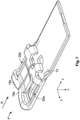
- Figure 1 shows a perspective view of the female electrical terminal 1 arranged along a receiving direction R for the receiving of a male electrical terminal, such as the male electrical terminal 100 described with reference to Figure 4 .
- the female electrical terminal 1 comprises, in the receiving direction R, a receiving portion 3 and a wiring portion 5.
- the receiving portion 3 defines a receiving hollow 7 configured to receive a male electrical terminal in the receiving direction R and along a central axis A defined by the female electrical terminal 1.
- the wiring portion 5 is configured for the attaching of an electrical wire, in particular of the conducting core of an electrical wire, to establish an electrical connection.
- the wiring portion 5 has a flat, thin shape and a rectangular wiring surface 9 extending in a plane x-y parallel to the receiving direction R. The edges 11 along the wiring surface 9 are chamfered.
- the wiring portion 5 is suitable for the attaching of a core of the electrical wire by ultrasonic metal welding on the wiring surface 9.
- the wiring portion of the female electrical terminal can be suited for an attaching of an electrical wire by alternative means, for example by soldering or crimping.
- the presently described embodiment is suitable for wire types having cross-sectional areas within a range of 0.1mm 2 to 120mm 2 , and more preferably within a range of 6mm 2 to 35mm 2 .
- the entire female electrical terminal 1, as well as the wiring portion 5 and the receiving portion 3, are plane-symmetrical with respect to a plane centred on the central axis A and parallel the receiving direction R.
- the receiving portion 3 comprises a base portion 13, forming a bottom side of the receiving portion 3 and providing a bottom surface 13a for the receiving hollow 7.
- the receiving portion comprises two lateral portions 15a, 15b arranged on either side of the base portion 13 with respect to the central axis A, symmetrically facing each other.
- the lateral portions 15a, 15b are bent with respect to the base portion 13 to form, that is, to close the envelope of, the receiving hollow 7.
- Each lateral portion 15a, 15b comprises, respectively, an end portion 17a, 17b providing a top surface 19a, 19b (see Figure 2, 3 and 5 ) of the receiving hollow 7, and a number of beams connecting the end portions 17a, 17b to the base portion 13.
- each lateral portion 15a, 15b comprises a first link beam 21a, 21b, and a second link beam, 23a, 23b, the link beams 21a-23a, 21b-23b being arranged in parallel and linking their respective end portion 17a, 17b to the base portion 13.
- Each first link beam 21a, 21b is arranged at a proximal end of the receiving portion 3 in the receiving direction R, and each second link beam 23a, 23b is arranged at a distal end of the receiving portion 3 in the receiving direction R.
- each first link beam 21a, 21b is arranged at the extremity of the terminal 1 at the opening 25 of the receiving hollow 7, and each second link beam 23a, 23b is arranged in a region of joining of the receiving portion 3 and the wiring portion 5.
- the lateral portions 15a, 15b of the terminal 1 further comprise, respectively, a support beam 27a, 27b, also linking a respective end portion 17a, 17b to the base portion 13.
- Each support beam 27a, 27b is arranged in parallel to and in between a respective first 21a, 21b and second 23a, 23b link beam.
- a first lateral space 29a, 29b is defined between a first link beam 21a, 21b, a support beam 27a, 27b, an end portion 17a, 17b and a base portion 13.
- a second lateral space 31a, 31b is defined between a support beam 27a, 27b, a second link beam 23a, 23b, an end portion 17a, 17b and a base portion 13.
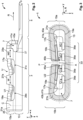
- Figure 2 shows a plane side view of the female electrical terminal 1 in a plane x-z parallel to the receiving direction R.
- terminal 1 in Figure 2 comprises a receiving portion 3 defining a receiving hollow 7, and a wiring portion 5.
- the receiving portion 3 comprises a base portion 13 and a lateral portion 15a.
- the lateral portion 15a comprises an end portion 17a, as well as, in sequence along the receiving direction R, a first link beam 21a, a support beam 27a and a second link beam 23a, each linking the end portion 17a to the base portion 13.
- the beams 21a, 27a, 23a are arranged in parallel and define the lateral spaces 29a, 31a.
- the support beam 23a comprises the notch 37 already described with reference to Figure 1 .
- the four lamellae 35 of the contacting portion 33 are bent inwardly from the base portion 13 into the receiving hollow 7. As visible for example on Figure 6 , the lamellae 35 extend along the receiving direction R
- a male electrical terminal such as terminal 100 shown in Figure 4
- a contact normal force is applied on the male electrical terminal by female electrical terminal.
- contact normal forces C1 are applied by the lamellae 35 on the male terminal
- contact normal forces C2 are applied by the end portions 17a, 17b on the male electrical terminal.
- the contact normal forces C1, C2 are related to the resilience of the lamellae 35 and the end portions 17a, 17b, which in turn depends on their respective structural arrangement and material properties.
- the male electrical terminal is inserted in the hollow 7 with an insertion force sufficient to overcome the contact normal forces C1, C2, i.e. the resilience of the lamellae 35 and the end portions 17a, 17b, and frictional forces.
- an electrical contact is realized between an insertion portion of the male terminal on the one hand, and the lamellae 35 and the end portions 17a, 17b on the other hand.
- the male electrical terminal is extracted with an extraction force sufficient to overcome the contact normal forces C1, C2, i.e. the resilience of the lamellae 35 and the end portions 17a, 17b, and frictional forces.
- the insertion force and the extraction force are thus directly linked to the contact normal force.
- the insertion portion 103 has a thickness L1 dimensioned to be greater than a gap of the receiving hollow 7, for example the gap between edge points 45a, 45b and opposite lamellae 35.
- the insertion portion 103 can have a thickness L1 between 0.5mm and 2mm, and the gap be between 0.3mm and 1.8mm wide.
- the thickness L1 can be of 0.792 +/-0.02mm and the gap be 0.64mm +/- 0.3mm wide.
- the insertion portion 103 has a first surface 109, facing downwards in a Cartesian direction z orthogonal to the receiving direction R, and a second surface 111, opposite the first surface 109.
- the inventive female electrical terminal 1, and the electrical terminal assembly resulting thereof, provides a support beam 27a, 27b which is advantageously suited to be adapted or modified to an application-specific need.
- the support beam 27a, 27b predominantly contributes to or determines the contact normal force C1, C2 of the terminal 1.
- the arrangement of the support beam 27a, 27b allows for a convenient modification of its structure in accordance with an application-specific requirement of the female electrical terminal 1.
- the female electrical terminal 1 can be cost-efficiently mass-produced and used across a variety of applications and environments, and at the same time be more accurately adapted to the vibrational load of the application. Thus, the user comfort is increased and the risk of damage to contact surfaces during use reduced, without any loss in electrical connection reliability.
- An exemplary method for manufacturing the terminal 1 will described in the following.
- a second step II executed after the providing step I, the sheet metal blank is formed to the desired shape.
- the sheet metal blank can formed by stamping, punching, cutting, machining, or any other suitable process to forming the sheet metal blank to the desired shape.
- the desired shape will be described with reference to Figure 6 , which illustrates a formed sheet metal 200, after conclusion of the bending step II and the modification step III, but prior to a subsequent bending step IV.
- Figure 6 shows a plane top view of the formed sheet metal 200.
- the sheet metal blank of step I is formed to comprise a wiring portion 5a for the attaching of an electrical wire, and a receiving portion 3 for the receiving of, and electrical contacting with, a male electrical terminal 100 in a receiving direction R.
- the wiring portion 5a shown on Figure 6 is larger than the wiring portion 5 of the female electrical terminal 1 and corresponds to an alternative to, or a preliminary stage of, the wiring portion 5.
- the large wiring portion 5a can be either reduced to a wiring portion 5 for ultrasonic welding, as illustrated by the dashed line, or bent to be suitable for crimping.
- the wiring portion 5a comprises, along an edge opposed to the receiving portion 3, guiding holes 6a and material cut-outs 6b.
- the circle-shaped guiding holes 6a are configured to facilitate a continuous guiding of the sheet metal blank in strip inside a stamping tool.
- the square-shaped material cut-outs 6b serve to reduce mass and save sheet metal material.
- a first link beam 21, 21b, a support beam 27a, 27b, and a second link beam 23a, 23b is arranged, in parallel and in sequence in the receiving direction R, thus defining a first lateral space 29a, 29b and a second lateral space 31a, 31b between the base portion 13 and respective end portions 19a, 19b.
- the receiving portion 3 further comprises the through hole 39.
- the lateral portions 15a, 15b comprise the rear protrusions 43a, 43b, and the respective notches 37.
- the contacting portion 33 comprises the four lamellae 35.
- the lamellae 35 extend along a length L2 of the base portion 13, for example between 20% and 80%, here around 60%, of the total length of the base portion 13.
- the base portion 13 is configured to form a bottom surface 13a for a receiving hollow 7 of the manufactured female electrical terminal 1.
- the end portions 17a, 17b of the lateral portions 15a, 15b are configured to form a top surface 19a, 19b for a receiving hollow 7 of the manufactured female electrical terminal 1.
- the rear protrusions 41a, 41b of the lateral portions 15a, 15b are configured to form a top surface 19a, 19b for a receiving hollow 7 of the manufactured female electrical terminal 1.
- the width V of the receiving hollow 7, corresponding to the width of the base portion 13, determines the width of the insertion portion 103 of the male electrical terminal.
- the width V is 12mm
- the width of the insertion portion of a suitable mating male electrical terminal 100 is 8mm.
- the support beam 27a, 27b has predetermined dimensions including a thickness, a width along the receiving direction R, and a length.
- the predetermined thickness can be the thickness T0 of the sheet metal.
- the predetermined width can be the width W0 of the second link beam 23a, 23b.
- the predetermined length can be the length L0 of the first link beam 21a, 21b.
- the modification of the dimension is preferably implemented as a function of an insertion force requirement of the insertion of the male electrical terminal 100 in the receiving hollow 7, in particular an insertion force minimum and/or maximum, or of a removal force requirement of the removal of the male electrical terminal 100 from the receiving hollow 7, in particular a removal force minimum and/or maximum, or of a contact normal force C1, C2 requirement of the electrical contact of the male electrical terminal 100 received in the female electrical terminal 1, in particular a contact normal force C1, C2 minimum and/or maximum.
- the modification should be dimensioned obtain a structural resilience of the female electrical terminal yielding a contact normal force C1, C2 superior to the vibration-induced acceleration forces expected on the electrical terminal assembly.
- vibration-induced acceleration forces can range, depending on the environment and the mass, i.e. momentum, between 0.009N and 70N. This the expected acceleration force value may provide a minimal contact normal force requirement.
- the presently described second embodiment of the invention provides for the manufacture of a female electrical terminal, which can be assembled with a male electrical terminal to an electrical assembly having a contact normal force greater than the vibration acceleration force of the application environment.
- the contact normal force C1, C2 can be modified, for example reduced from a generic value much greater, for example 50% greater, to a value slightly greater, specifically only up to 10% greater, than the vibration acceleration force expected in the application environment. Therefore, user comfort is maximized during installation, without jeopardizing the reliability of the electrical connection.
- a cable installer may prefer the necessary insertion force, when assembling a female electrical terminal according to the invention, such as terminal 1, with a male electrical terminal, such as terminal 100, to be limited. Therefore, a modus of assembly may provide a maximal insertion force requirement.
- the mass connected to an electrical terminal contributes by momentum to the vibrational load, i.e. the acceleration forces that are experienced by an electrical terminal assembly.
- the lengths and the size, such as the diameter or cross-sectional area of the conductive core, of the wires attached to the wiring portions 5, 5a, 105 contribute to the acceleration forces experienced by the terminal assembly.
- the dimension such as the thickness, width or length
- the dimension is modified as a function of a property, in particular the diameter and/or size of the core, of the electrical wire intended in the application.
- the thickness of the support beam 27a. 27b can be reduced by 50% for an application-specific requirement of wires having diameters below 10mm 2 .
- the smaller the application-specific wire size the lower the acceleration forces to be expected, and therefore the further the dimensions of the support beam 27a, 27b can be reduced.
- a further step IV performed after the modifying step III, the lateral portions 15a, 15b are bent to form the receiving hollow 7, in line with the female electrical terminal 1 of the first embodiment.
- the flat shape of the formed sheet metal 200 is brought into the desired shape of the female electrical terminal 1, forming the receiving hollow 7.
- the depression region U and the lamellae 35 can also be bent to protrude inwardly into the receiving hollow 7, and the rear protrusions 41a, 41b can be bent to close the receiving hollow.
- the modifying step III is executed after the bending step IV.
- This can be more cumbersome and require different conversion kit tools, but provides the advantage of delaying the modification of a generic female electrical terminal to the moment of installation, enabling a real-time adaptation to an application-specific requirement.
- FIG. 7 shows a female electrical terminal 1', manufactured by the method described above concerning the second embodiment of the invention like the female electrical terminal 1 of Figure 1 .
- the female electrical terminal 1' thus represents an alternative product of the method of the second embodiment described here above.
- the female electrical terminal 1' differs from the female electrical terminal in that the support beams 27a, 27b have been completely removed. In other words, in step III of the method, the dimension T or W or L has been reduced to a value of zero.
- the female electrical terminal 1' thus does not comprise a support beams 27a, 27b linking end portions 17a, 17b to the base portion 13.
- the first 29a, 29b and second 31a, 31b lateral spaces of the female electrical terminal 1 are thus in Figure 7 joined to form a respective combined lateral space 30a, 30b.
- the contact normal force C1, C2 (cf. Figure 3 )
- the insertion force and the extraction force are significantly reduced, for example by up to 50%.
- an insertion force measured for the female electrical terminal 1' falls within the range 11.6N to 20.6N, while the same measurement applied to a corresponding female electrical terminal 1 falls within the range 25.4N to 36.9N, with an average reduction of insertion force of around 47%.
- similar measurements of an extraction force yield average extraction force reduction of 51%, for the female electrical terminal 1' when compared to the female electrical terminal 1.
Landscapes
- Engineering & Computer Science (AREA)
- Manufacturing & Machinery (AREA)
- Manufacturing Of Electrical Connectors (AREA)
- Connections Effected By Soldering, Adhesion, Or Permanent Deformation (AREA)
Abstract
Description
- The present invention relates to a method for manufacturing a female electrical terminal, to a female electrical terminal, and to an electrical terminal assembly.
- It is known to establish an electrical connection by assembling together two electrical terminals, each respectively attached to an end of a conducting electrical wire. For example, typically, a male electrical terminal is inserted in a receiving hollow of a female electrical terminal to realize an electrical contact. The quality of the electrical connection is determined at least partly by the forces holding together the assembled electrical terminals.
- For example, when a male electrical terminal is received in a female electrical terminal, the contact normal force exerted by the mechanical structure of the female electrical terminal structure on the received male electrical terminal can counteract relative movements of the terminals and prevent an unwanted extraction of the male electrical terminal. In particular, the contact normal force should be higher than the mechanical vibration-induced acceleration forces exerted on the electrical terminal assembly.
- However, the intensity of the vibrational load exerted on the electrical terminal assembly is specific to each environment and each application of the electrical terminal assembly. For example, the level of mechanical vibration in a vehicle application in proximity to the engine can be much higher than, for example, in an immobile and/or environmentally insulated industrial application. Further, the electrical current intensity to be carried by the electrical connection may vary from application to application, and thus, within a range, the dimensions, i.e. mass, of the conducting wires to be attached to the terminals may also vary, thereby impacting the vibrational load on the assembly.
- For cost-efficiency purposes, it is therefore typical to design electrical terminal assemblies conservatively, providing for a sufficiently high contact normal force to guarantee a reliable electrical connection in a wide range of environments and applications. In other words, in conventional electrical terminal designs the contact normal force, or contact structural resilience, is over-dimensioned with respect to the real application requirement, exceeding the actual requirements by an unwarranted margin.
- This leads to unneeded user discomfort when assembling and/or disassembling electrical terminal systems. In particular, the insertion and/or extraction of a male electrical terminal in or from the receiving hollow of the female electrical terminal can require excessive force for the user, for example for the cable installer.
- Further, a risk of damage to the metal plating of portions of the electrical terminals during insertion and/or extraction is increased, reducing the reusability of the terminals and the quality of the electrical connection.
- It is therefore an object of the present invention to provide an electrical connection solution overcoming the described deficiency in prior art. In particular, it is an object of the present invention to provide a cost-efficient electrical terminal assembly providing a better balance of electrical connection reliability and user comfort.
- This object is achieved with a method for manufacturing a female electrical terminal, comprising the steps of:
- a) Providing a sheet metal blank,
- b) Forming the sheet metal blank to comprise a wiring portion for the attaching of an electrical wire, and a receiving portion for the receiving of a male electrical terminal in a receiving direction, the receiving portion comprising a base portion and two lateral portions,
- the base portion being configured to form a bottom surface of a receiving hollow of the manufactured female electrical terminal and comprising a contacting portion for an electrical contacting with the received male electrical terminal, and
- each lateral portion comprising, respectively: an end portion configured to form a top surface of the receiving hollow, at least one link beam linking the end portion to the base portion, and a support beam also linking the end portion to the base portion, the support beam having predetermined dimensions including a thickness, a width along the receiving direction, and a length in a plane orthogonal to the receiving direction, and
- c) Bending the lateral portions to form the receiving hollow.
- The method is characterized in further comprising an additional step d) of modifying, in particular, reducing, at least one dimension of the support beam, in particular the thickness, and/or the width, and/or the length.
- According to this method, a female electrical terminal is manufactured that comprises a support beam linking the base portion, forming a bottom surface of the receiving hollow, and the end portion, configured to form a top surface of the receiving hollow. That is, the support beam links, or connects together structurally, the end portion and the base portion in between which the male electrical terminal is held when it is received in the receiving hollow. The dimensions of the support beam therefore contribute to the resilience property of an elastic spreading apart of the end portion and the base portion, respectively defining a top and bottom surface of the receiving hollow female electrical terminal.
- By modifying a dimension of the support beam, the contact normal force of the electrical terminal assembly, when a male electrical terminal is received in the receiving hollow of the female electrical terminal, is also modified. Thus, the female electrical terminal can be modified to match more closely the application-specific need, with respect to the contact normal force. For example, a reduction of a dimension such as the thickness of the support beam can reduce the contact normal force of the electrical terminal assembly, and consequently also facilitate insertion and extraction of the male electrical terminal.
- In one aspect of the method, step d) can be executed between step b) and step c). When the support beam is modified before the bending, the modification can be implemented conveniently with the same tool used to form, for example stamp or punch, the sheet metal blank.
- In another aspect of the method, step d) can be executed after step c). In this configuration, the support beam is modified after the bending. For example, the female electrical terminal can be manufactured, transported, sold and stored with a generic, unmodified, support beam. The modification of step d) can then be performed during electrical terminal assembly installation by a conversion tool kit, in accordance with the need of the specific installation.
- In one aspect of the method, the dimension can be modified, in particular reduced, as a function of a property, in particular the diameter and/or size of the core, of the electrical wire to be attached to the wiring portion. The type of electrical wire, for example the diameter or cross-sectional area, together with the length of the electrical wire, determines the mass of the wire and therefore the acceleration force compounded by vibrations on the electrical terminal assembly. In this configuration, the female electrical terminal can be adapted to provide a contact normal force matching need corresponding to the type of the electrical wire.
- In one aspect of the method, the dimension can be modified, in particular reduced, as a function of an insertion force requirement of the insertion of the male electrical terminal in the receiving hollow, in particular an insertion force minimum and/or maximum. In this configuration, the female electrical terminal can be adapted to improve user comfort during male terminal insertion without risking reliability of the electrical connection of the electrical terminal assembly.
- In one aspect of the method, the dimension can be modified, in particular reduced, as a function of a removal force requirement of the removal of the male electrical terminal from the receiving hollow, in particular a removal force minimum and/or maximum. In this configuration, the female electrical terminal can be adapted to improve user comfort during male terminal extraction without risking reliability of the electrical connection of the electrical terminal assembly.
- In one aspect of the method, the dimension can be modified, in particular reduced, as a function of a contact normal force requirement of the electrical contact of the male electrical terminal received in the female electrical terminal, in particular a contact normal force minimum and/or maximum. In this configuration, the female electrical terminal can be adapted to provide a contact normal force matching more closely an application-specific need. Thus, user comfort can be improved during installation, in particular male terminal insertion and/or extraction, and the risk of damage to the metal plating of portions of the electrical terminals during insertion and/or extraction can be reduced.
- The object of the invention is also achieved with a female electrical terminal comprising a wiring portion for the attaching of an electrical wire, and a receiving portion for the receiving of a male electrical terminal in a receiving direction in a receiving hollow, the receiving portion comprising a base portion and two lateral portions, wherein the two lateral portions are bent with respect to the base portion to form the receiving hollow, the base portion forming a bottom surface of the receiving hollow and comprising a contacting portion for an electrical contacting with the received male electrical terminal.
- The female electrical terminal is characterized in that each lateral portion comprises, respectively: an end portion forming a top surface of the receiving hollow, a first link beam and a second link beam, the link beams arranged in parallel and linking the end portion to the base portion, wherein the first link beam is arranged at a proximal end of the receiving portion in the receiving direction, and the second link beam is arranged at a distal end of the receiving portion in the receiving direction, and a support beam also linking the end portion to the base portion, the support beam being arranged in parallel to and in between the first and the second link beam.
- A female electrical terminal thus configured includes in a side area at least three beams, at least one of which, the support beam, is arranged between the other two (link) beams. The design, i.e. structural geometry, of the support beam therefore predominantly contributes to or determines the contact normal force of the terminal, that is, when assembled with a mating male electrical terminal. Specifically, the contact normal force is determined by the resilience of the bent end portion of the lateral portion linked to the base portion by the link beams and the support beam, and, for example, a thickness of an insertion portion of the mating male electrical terminal.
- The arrangement of the support beam allows for a convenient modification of its structure in accordance with an application-specific requirement of the female electrical terminal. The modification is convenient both in a pre-bending state, when the formed sheet metal is yet unbent, and in a post-bending state, when the sheet metal is bent to form the receiving hollow of the female electrical terminal.
- The female electrical terminal according to the invention can be cost-efficiently mass-produced and used across a variety of applications and environments, and at the same time be more accurately adapted to the vibrational load of the application. Thus, the user comfort is increased and the risk of damage to contact surfaces during use reduced, without any loss in electrical connection reliability.
- In one aspect of the terminal, the support beam can have a thickness smaller, in particular 5% to 90% smaller, than a corresponding thickness of the first and/or of the second link beam. In this configuration, the support beam has a reduced thickness, and thus the resilience of the bent end portion with respect to the base portion is also reduced, reducing the contact normal force. A thus configured female electrical terminal can be more suitable with lower-than-maximal vibrational load requirements.
- In one aspect of the terminal, the support beam can have a width along the receiving direction smaller, in particular 5% to 90% smaller, than a corresponding width of the first and/or of the second link beam. In this configuration, the support beam has a reduced width, and thus the resilience of the bent end portion with respect to the base portion is also reduced, reducing the contact normal force. A thus configured female electrical terminal can be more suitable with lower-than-maximal vibrational load requirements.
- In one aspect of the terminal, the second link the beam can comprise a notch in a region of joining of the second link beam and the base portion, in particular wherein the notch faces in the receiving direction and has a depth of 10% to 50% of the width of the second link beam. A notch placed in a region joining of the second link beam and the base portion can avoid an accumulation of stress in the region, which is notable specifically in the case of ultrasonic welding of the core of the electrical wire to the wiring portion. If the natural frequency of the welding and of the terminal coincide, the amplitude of micro-motions at the region joining the wiring portion to the receiving portion can increase. Thus, the notch reduces the risk of resonance-effect-related damage to the receiving portion.
- In one aspect of the terminal, the end portions of the respective lateral portions, when bent to form the receiving hollow, can define, in a plane orthogonal to the receiving direction and/or in a plane parallel to the receiving direction, a U-shaped top surface. When end portions are bent to form a U-shape in the plane parallel to the receiving direction and/or the plane orthogonal to the receiving direction, the edges can be softened and chafing or damage to metal plating reduced.
- The invention further relates to an electrical terminal assembly comprising a female electrical terminal according to one of the above-described aspects, or manufactured by the method according to any one of above-described aspects, and a male electrical terminal, wherein the male electrical terminal is received in the receiving hollow such that a first surface of the male electrical terminal abuts with the contacting portion of the female electrical terminal, and a second surface of the male electrical terminal opposed to the first surface abuts with the end portions of the female electrical terminal, realizing the electrical contacting.
- In a thusly configured electrical terminal assembly, the contact normal force of the male electrical terminal received in the receiving hollow of the female electrical terminal can be more closely adapted to the application, as described above with respect to the method for manufacturing and the female electrical terminal.
- In one aspect of the terminal assembly, a thickness, and/or a width along the receiving direction, and/or a length in a plane orthogonal to the receiving direction, of the support beam, can be a function of a property, in particular the diameter and/or size of the core, of the electrical wire to be attached to the wiring portion. In this way, the contact normal force can be more precisely adapted to the wire type, and thus at the same time provide higher user comfort during electrical terminal assembly installation.
- In one aspect of the terminal assembly realizing an electrical connection in an application environment, the contact normal force of the electrical contacting can correspond to, in particular be greater than, preferably up to 10% greater than, the vibration acceleration force of the application environment. In comparison to prior art, this electrical terminal assembly can have a contact normal force adapted to a vibration acceleration force related to the application, and thus guarantee a reliable electrical connection without dimensioning the contact normal force too excessively.
- These, as well as other objects and advantages of this invention will be more completely understood and appreciated by careful study of the following more detailed description of the presently preferred exemplary aspects and embodiments of the invention, taken in conjunction with accompanying drawings, in which:
-
Figure 1 shows a perspective view of a female electrical terminal according to a first embodiment of the invention; -
Figure 2 shows a side view of the terminal ofFigure 1 ; -
Figure 3 shows a cross-sectional view of the terminal ofFigure 1 ; -
Figure 4 shows a side view of a male electrical terminal; -
Figure 5A illustrates schematically the steps of a method according to a second embodiment of the invention; -
Figure 5B illustrates schematically the steps of a method in a variant of the second embodiment; -
Figure 6 shows a plane top view of a formed sheet metal in a method according to a second embodiment of the invention; -
Figure 7 shows the female electrical terminal ofFigure 1 modified according to the method of the second embodiment. - A female electrical terminal according to a first embodiment of the invention will now be described with reference to
Figures 1 ,2 and 3 . The femaleelectrical terminal 1 shown onFigures 1 ,2 and 3 can be obtained by a method for manufacturing a female electrical terminal according to the invention, of which an embodiment will be described subsequently. - In this example, the female
electrical terminal 1 is manufactured by a stamping and bending of sheet metal, in particular of a copper-nickel-silicon alloy or a copper-chrome-titanium-silicon alloy. In some variants, the sheet metal can comprise a metal plating to enhance corrosion-resistance and conductivity properties, in particular a silver plating. -
Figure 1 shows a perspective view of the femaleelectrical terminal 1 arranged along a receiving direction R for the receiving of a male electrical terminal, such as the maleelectrical terminal 100 described with reference toFigure 4 . The femaleelectrical terminal 1 comprises, in the receiving direction R, a receivingportion 3 and awiring portion 5. The receivingportion 3 defines a receiving hollow 7 configured to receive a male electrical terminal in the receiving direction R and along a central axis A defined by the femaleelectrical terminal 1. - The
wiring portion 5 is configured for the attaching of an electrical wire, in particular of the conducting core of an electrical wire, to establish an electrical connection. Thewiring portion 5 has a flat, thin shape and arectangular wiring surface 9 extending in a plane x-y parallel to the receiving direction R. Theedges 11 along thewiring surface 9 are chamfered. - In this embodiment, the
wiring portion 5 is suitable for the attaching of a core of the electrical wire by ultrasonic metal welding on thewiring surface 9. However, in alternative embodiments, the wiring portion of the female electrical terminal can be suited for an attaching of an electrical wire by alternative means, for example by soldering or crimping. The presently described embodiment is suitable for wire types having cross-sectional areas within a range of 0.1mm2 to 120mm2, and more preferably within a range of 6mm2 to 35mm2. - The entire female
electrical terminal 1, as well as thewiring portion 5 and the receivingportion 3, are plane-symmetrical with respect to a plane centred on the central axis A and parallel the receiving direction R. - To this effect, the receiving
portion 3 comprises abase portion 13, forming a bottom side of the receivingportion 3 and providing abottom surface 13a for the receiving hollow 7. In addition, the receiving portion comprises twolateral portions base portion 13 with respect to the central axis A, symmetrically facing each other. Thelateral portions base portion 13 to form, that is, to close the envelope of, the receiving hollow 7. - Each
lateral portion end portion top surface Figure 2, 3 and5 ) of the receiving hollow 7, and a number of beams connecting theend portions base portion 13. Specifically, eachlateral portion first link beam respective end portion base portion 13. Eachfirst link beam portion 3 in the receiving direction R, and eachsecond link beam portion 3 in the receiving direction R. In other words, eachfirst link beam terminal 1 at theopening 25 of the receiving hollow 7, and eachsecond link beam portion 3 and thewiring portion 5. - According to the present invention, the
lateral portions terminal 1 further comprise, respectively, asupport beam respective end portion base portion 13. Eachsupport beam - Therefore, on each symmetrical side of the receiving
portion 3 with respect to the central axis A, a firstlateral space first link beam support beam end portion base portion 13. Similarly, on each symmetrical side of the receivingportion 3 with respect to the central axis A, a secondlateral space support beam second link beam end portion base portion 13. - The support beams 27a, 27b have a thickness T, which corresponds in the embodiment of
Figure 2 to the thickness of the bent sheet metal further reduced by a predetermined quantity. That is, the maximum thickness T of thesupport beam second link beams - In the present embodiment, the thickness T is reduced with respect to T0 by 5%. However, in variants, the thickness T can be reduced by other values. In particular, the thickness T can be 5% to 90% smaller, than a corresponding thickness of the first and/or second link beam.
- Further, the
support beams - The support beams 27a, 27b also have a length L, corresponding to the extension of the path of the
support beams base portion 13 andend portions - The
base portion 13 comprises a contactingportion 33 consisting of fourlamellae 35, stamped in thebase portion 13 and bent upwards, that is, into the receiving hollow 7, for an electrical contacting with a received male electrical terminal. Only onelamellae 35 is visible onFigure 1 . The configuration and functionality of the contactingportion 33 will be further described in view ofFigures 3 and6 . -
Figure 1 also shows that thesecond link beam 23a comprises anotch 37 in a region of joining of thesecond link beam 23a and thebase portion 13. Thenotch 37 faces in the receiving direction R and has a depth of 10% to 50% of the width of the second link beam. A symmetrically arranged notch in thesecond link beam 23b is not visible onFigure 1 . Thenotches 37 prevent an accumulation of stress in a critical region of bending and joining from micro-motions during ultrasonic metal welding. - In a region of joining of the
wiring portion 5 and thebase portion 13 of the receiving portion, a throughhole 39 traverses the metal sheet. The throughhole 39 can be used as locking area for a locking of theterminal 1 to a housing, and also improves the plastic properties of theterminal 1 to facilitate bending during manufacture. Theend portions - Further, the
lateral portions end portions second link beams rear protrusions rear protrusions wiring portion 5 and are bent downwards, defining a rear surface 43 (seeFigure 3 and5 ) for the receiving hollow 7. Therear protrusions electrical terminal 1 along a direction z orthogonal to the receiving direction R, for example during handling and installation, and thus prevent plastic deformation. -
Figure 2 shows a plane side view of the femaleelectrical terminal 1 in a plane x-z parallel to the receiving direction R. As already previously described, terminal 1 inFigure 2 comprises a receivingportion 3 defining a receiving hollow 7, and awiring portion 5. The receivingportion 3 comprises abase portion 13 and alateral portion 15a. Thelateral portion 15a comprises anend portion 17a, as well as, in sequence along the receiving direction R, afirst link beam 21a, asupport beam 27a and asecond link beam 23a, each linking theend portion 17a to thebase portion 13. Thebeams lateral spaces support beam 23a comprises thenotch 37 already described with reference toFigure 1 . - The receiving hollow 7 is enclosed by a
bottom surface 13a (not visible onFigure 2 ), therear surfaces rear protrusions top surface end portions opening 25 for the receiving of a male electrical terminal in receiving direction R. - The
support beam 27a has a width W 10% smaller than the width W0 of thesecond link beam 23a, and a thickness T (not visible) 5% smaller than the thickness T0 of the unmodified sheet metal, here for example shown in a region of thewiring portion 5. - As can be seen on
Figure 2 , theend portions top surface end portions top surface end portions top surface - In the
end portions -
Figure 3 shows a cross-sectional view of the receivingportion 3 of the femaleelectrical terminal 1 according to the cross-sectional line C shown onFigures 1 and2. Figure 3 shows the plane of symmetry P parallel to the receiving direction R and the Cartesian direction x. Thus, arranged symmetrically arranged the plane P,Figure 3 shows thelateral portions first link beams end portions bottom surface 13a provided by thebase portion 13, thetop surfaces end portions rear surfaces rear protrusions - As described with respect to
Figure 2 , theend portions Figure 3 illustrates that the depression region also forms a second U-shape U2 in a plane orthogonal to the receiving direction R. The second U-shape U2 of the depression region U also softens theedge points end portions - The four
lamellae 35 of the contactingportion 33 are bent inwardly from thebase portion 13 into the receiving hollow 7. As visible for example onFigure 6 , thelamellae 35 extend along the receiving direction R - A male electrical terminal, such as
terminal 100 shown inFigure 4 , can be received in the receiving hollow 7 to establish an electrical contact and realize an electrical connection. When received in the hollow, a contact normal force is applied on the male electrical terminal by female electrical terminal. In particular, contact normal forces C1 are applied by thelamellae 35 on the male terminal, and contact normal forces C2 are applied by theend portions lamellae 35 and theend portions - To establish an electrical connection, the male electrical terminal is inserted in the hollow 7 with an insertion force sufficient to overcome the contact normal forces C1, C2, i.e. the resilience of the
lamellae 35 and theend portions lamellae 35 and theend portions lamellae 35 and theend portions -
Figure 4 shows a side view of a male electrical terminal suitable to be inserted in a female electrical terminal according to the invention, in particular thefemale terminal 1 described above. The maleelectrical terminal 100 offigure 4 comprises aninsertion portion 103 and awiring portion 105, separated by abridge portion 107. Theinsertion portion 103 is configured to be inserted by its pointeddistal end 101 in a receiving hollow of a female terminal, such as the receiving hollow 7. - The
insertion portion 103 has a thickness L1 dimensioned to be greater than a gap of the receiving hollow 7, for example the gap betweenedge points opposite lamellae 35. For example, theinsertion portion 103 can have a thickness L1 between 0.5mm and 2mm, and the gap be between 0.3mm and 1.8mm wide. In one example, the thickness L1 can be of 0.792 +/-0.02mm and the gap be 0.64mm +/- 0.3mm wide. Further, theinsertion portion 103 has afirst surface 109, facing downwards in a Cartesian direction z orthogonal to the receiving direction R, and asecond surface 111, opposite thefirst surface 109. - An electrical terminal system according to the invention comprises a female electrical terminal, such as the female
electrical terminal 1, and a male electrical terminal, such as the maleelectrical terminal 100. - An electrical terminal assembly is an assembled electrical terminal system, in which the female and the male electrical terminal have been assembled by an insertion of an insertion portion of the male electrical terminal in a receiving hollow defined by a receiving portion of the female electrical terminal. For example, in one embodiment of the invention, the male
electrical terminal 100 is received in the receiving hollow 7 such that thefirst surface 109 abuts with the contactingportion 33, specifically thelamellae 35, of the femaleelectrical terminal 1 and thesecond surface 111 abuts with theend portions edge points insertion portion 103 of the maleelectrical contact 100. - The inventive female
electrical terminal 1, and the electrical terminal assembly resulting thereof, provides asupport beam support beam terminal 1. The arrangement of thesupport beam electrical terminal 1. - The female
electrical terminal 1 can be cost-efficiently mass-produced and used across a variety of applications and environments, and at the same time be more accurately adapted to the vibrational load of the application. Thus, the user comfort is increased and the risk of damage to contact surfaces during use reduced, without any loss in electrical connection reliability. An exemplary method for manufacturing theterminal 1 will described in the following. - A method for manufacturing a female electrical terminal according to a second embodiment of the invention will now be described. The method is suitable for manufacturing the female
electrical terminal 1 of the first embodiment of the invention described here above. As schematically illustrated inFigure 5A , the method comprises four successive steps I, II, III and IV. - In a first step I, a sheet metal blank is provided. Preferably, the material of the sheet metal blank is a copper-nickel-silicon alloy or a copper-chrome-titanium-silicon alloy, and is entirely silver metal plated prior to beginning the method. In variants, no metal plating or a selective or partial metal plating is provided. In other variants, a metal plating is provided in between the any two of steps I, II, III and IV, or during any one of steps I, II, III and IV of the presently described method. Alternatively, the metal plating is provided after conclusion of the method for manufacturing a female electrical terminal.
- In a second step II, executed after the providing step I, the sheet metal blank is formed to the desired shape. The sheet metal blank can formed by stamping, punching, cutting, machining, or any other suitable process to forming the sheet metal blank to the desired shape. The desired shape will be described with reference to
Figure 6 , which illustrates a formedsheet metal 200, after conclusion of the bending step II and the modification step III, but prior to a subsequent bending step IV.Figure 6 shows a plane top view of the formedsheet metal 200. - The sheet metal blank of step I is formed to comprise a
wiring portion 5a for the attaching of an electrical wire, and a receivingportion 3 for the receiving of, and electrical contacting with, a maleelectrical terminal 100 in a receiving direction R. Thewiring portion 5a shown onFigure 6 is larger than thewiring portion 5 of the femaleelectrical terminal 1 and corresponds to an alternative to, or a preliminary stage of, thewiring portion 5. For example, thelarge wiring portion 5a can be either reduced to awiring portion 5 for ultrasonic welding, as illustrated by the dashed line, or bent to be suitable for crimping. Thewiring portion 5a comprises, along an edge opposed to the receivingportion 3, guidingholes 6a and material cut-outs 6b. The circle-shaped guidingholes 6a are configured to facilitate a continuous guiding of the sheet metal blank in strip inside a stamping tool. The square-shaped material cut-outs 6b serve to reduce mass and save sheet metal material. - The receiving
portion 3 comprises abase portion 13 and twolateral portions base portion 13 with respect to the receiving direction R. Thebase portion 13 comprises a contactingportion 33 for an electrical contacting with the received maleelectrical terminal 100. Eachlateral portion end portion first link beam support beam second link beam end portion base portion 13. In eachlateral portion first link beam 21, 21b, asupport beam second link beam lateral space lateral space base portion 13 andrespective end portions - The receiving
portion 3 further comprises the throughhole 39. Thelateral portions rear protrusions respective notches 37. The contactingportion 33 comprises the fourlamellae 35. Thelamellae 35 extend along a length L2 of thebase portion 13, for example between 20% and 80%, here around 60%, of the total length of thebase portion 13. - As understood in view of the female
electrical terminal 1, thebase portion 13 is configured to form abottom surface 13a for a receiving hollow 7 of the manufactured femaleelectrical terminal 1. Similarly, theend portions lateral portions top surface electrical terminal 1. Similarly, therear protrusions lateral portions top surface electrical terminal 1. - The width V of the receiving hollow 7, corresponding to the width of the
base portion 13, determines the width of theinsertion portion 103 of the male electrical terminal. In one example, the width V is 12mm, and the width of the insertion portion of a suitable mating maleelectrical terminal 100 is 8mm. - After step II, the
support beam second link beam first link beam - In a characterizing step III performed after the forming step II, a dimension of the
support beam Figure 6 corresponding to the femaleelectrical terminal 1 ofFigure 1 , the width ofsupport beam width W 5% smaller than the width W0. Additionally, the thickness T has been reduced with respect to the predetermined thickness T0 (not visible ofFigure 6 ). In this example, the length L has not been modified with respect to the length L0. Alternatively, to obtain the femaleelectrical terminal 1 ofFigure 1 , the dimensions of the support beam can be modified to match those described with reference to theterminal 1. - The modification of the dimension is preferably implemented as a function of an insertion force requirement of the insertion of the male
electrical terminal 100 in the receiving hollow 7, in particular an insertion force minimum and/or maximum, or of a removal force requirement of the removal of the male electrical terminal 100 from the receiving hollow 7, in particular a removal force minimum and/or maximum, or of a contact normal force C1, C2 requirement of the electrical contact of the maleelectrical terminal 100 received in the femaleelectrical terminal 1, in particular a contact normal force C1, C2 minimum and/or maximum. - In this way, an optimal balance between minimal insertion and/or extraction forces, for user comfort, and sufficient contact normal forces, for a reliable electrical connection, can be achieved. Specifically, the modification should be dimensioned obtain a structural resilience of the female electrical terminal yielding a contact normal force C1, C2 superior to the vibration-induced acceleration forces expected on the electrical terminal assembly. For example, vibration-induced acceleration forces can range, depending on the environment and the mass, i.e. momentum, between 0.009N and 70N. This the expected acceleration force value may provide a minimal contact normal force requirement.
- Therefore, the presently described second embodiment of the invention provides for the manufacture of a female electrical terminal, which can be assembled with a male electrical terminal to an electrical assembly having a contact normal force greater than the vibration acceleration force of the application environment. At the same time, with the modification of the
support beams - On the other hand, a cable installer may prefer the necessary insertion force, when assembling a female electrical terminal according to the invention, such as
terminal 1, with a male electrical terminal, such asterminal 100, to be limited. Therefore, a modus of assembly may provide a maximal insertion force requirement. - As mentioned, the mass connected to an electrical terminal contributes by momentum to the vibrational load, i.e. the acceleration forces that are experienced by an electrical terminal assembly. For example, the lengths and the size, such as the diameter or cross-sectional area of the conductive core, of the wires attached to the
wiring portions - Therefore, in one variant, the dimension, such as the thickness, width or length, is modified as a function of a property, in particular the diameter and/or size of the core, of the electrical wire intended in the application. As an illustrative example, the thickness of the
support beam 27a. 27b can be reduced by 50% for an application-specific requirement of wires having diameters below 10mm2. Generally, the smaller the application-specific wire size, the lower the acceleration forces to be expected, and therefore the further the dimensions of thesupport beam - In a further step IV performed after the modifying step III, the
lateral portions electrical terminal 1 of the first embodiment. In this step, the flat shape of the formedsheet metal 200 is brought into the desired shape of the femaleelectrical terminal 1, forming the receiving hollow 7. Specifically, in this step, the depression region U and thelamellae 35 can also be bent to protrude inwardly into the receiving hollow 7, and therear protrusions - In one variant schematically illustrated in
Figure 5B , the modifying step III is executed after the bending step IV. This can be more cumbersome and require different conversion kit tools, but provides the advantage of delaying the modification of a generic female electrical terminal to the moment of installation, enabling a real-time adaptation to an application-specific requirement. -
Figure 7 shows a female electrical terminal 1', manufactured by the method described above concerning the second embodiment of the invention like the femaleelectrical terminal 1 ofFigure 1 . The female electrical terminal 1' thus represents an alternative product of the method of the second embodiment described here above. The female electrical terminal 1' differs from the female electrical terminal in that thesupport beams - The female electrical terminal 1' thus does not comprise a support beams 27a, 27b linking
end portions base portion 13. The first 29a, 29b and second 31a, 31b lateral spaces of the femaleelectrical terminal 1 are thus inFigure 7 joined to form a respective combinedlateral space Figure 3 ), the insertion force and the extraction force are significantly reduced, for example by up to 50%. In one example, an insertion force measured for the female electrical terminal 1' falls within the range 11.6N to 20.6N, while the same measurement applied to a corresponding femaleelectrical terminal 1 falls within the range 25.4N to 36.9N, with an average reduction of insertion force of around 47%. In this example, similar measurements of an extraction force yield average extraction force reduction of 51%, for the female electrical terminal 1' when compared to the femaleelectrical terminal 1. - The features of the various aspects, variants, and embodiments of the invention described in the present specification can be freely combined with each other to obtain further embodiments or examples according to the invention.
-
- 1 female electrical terminal
- 3 receiving portion
- 5 wiring portion
- 5a alternative wiring portion
- 6a guiding hole
- 6b material cut-out
- 7 receiving hollow
- 9 wiring surface
- 11 chamfered edges of the wiring surface
- 13 base portion
- 13a bottom surface of the receiving hollow
- 15a, 15b lateral portion
- 17a, 17b end portion
- 19a, 19b top surface of the receiving hollow
- 21a, 21b first link beam
- 23a, 23b second link beam
- 25 opening to the receiving hollow
- 27a, 27b support beams
- 29a, 29b first lateral space
- 30a, 30b combined lateral space
- 31a, 31b second lateral space
- 33 contacting portion
- 35 lamellae
- 37 notch
- 39 through hole
- 41a, 41b rear protrusions
- 43a, 43b rear surface
- 45a, 45b edge points of the end portions
- 100 male electrical terminal
- 101 pointed tip
- 103 insertion portion
- 105 wiring portion
- 107 bridge portion
- 109 first surface of the insertion portion
- 111 second surface of the insertion portion
- 200 formed sheet metal prior to bending
- A central axis
- C cross-sectional plane
- C1 contact normal force
- C2 contact normal force
- L length of the support beam
- L1 thickness of the insertion portion of the male terminal
- L2 length of lamellae
- P symmetrical plane
- R receiving direction
- T thickness of the support beam
- T0 thickness of the sheet metal blank
- U depression region
- U1 top surface U-shape in the depression region
- U2 top surface U-shape in the depression region
- V width of the receiving hollow
- W width of the support beam
- W0 width of the second link beam
- x,y,z Cartesian directions
Claims (15)
- Method for manufacturing a female electrical terminal (1) comprising the steps of:a) Providing a sheet metal blankb) Forming the sheet metal blank (200) to comprise:a wiring portion (5) for the attaching of an electrical wire, anda receiving portion (3) for the receiving of a male electrical terminal (100) in a receiving direction (R), the receiving portion (3) comprising a base portion (13) and two lateral portions (15a, 15b),the base portion (13) being configured to form a bottom surface (13a) of a receiving hollow (7) of the manufactured female electrical terminal (1) and comprising a contacting portion (33) for an electrical contacting with the received male electrical terminal (100), andeach lateral portion (15a, 15b) comprising, respectively:an end portion (17a, 17b) configured to form a top surface (19a, 19b) of the receiving hollow (7),at least one link beam (21a, 21b, 23a, 23b) linking the end portion (17a, 17b) to the base portion (13), anda support beam (27a, 27b) also linking the end portion (17a, 17b) to the base portion (13),the support beam having predetermined dimensions including a thickness (T), a width (W) along the receiving direction (R), and a length (L) in a plane orthogonal to the receiving direction (R),c) Bending the lateral portions (15a, 15b) to form the receiving hollow (7).characterized in further comprising an additional step d) of modifying, in particular, reducing, at least one dimension (T, W, L) of the support beam (27a, 27b), in particular the thickness (T), and/or the width (W), and/or the length (L).
- Method according to claim 1, wherein step d) is executed between step b) and step c).
- Method according to claim 1, wherein step d) is executed after step c).
- Method according to any one of claims 1 to 3, wherein the dimension (T, W, L) is modified, in particular reduced, as a function of a property, in particular the diameter and/or size of the core, of the electrical wire to be attached to the wiring portion (5).
- Method according to any one of claims 1 to 4, wherein the dimension is modified, in particular reduced, as a function of an insertion force requirement of the insertion of the male electrical terminal (100) in the receiving hollow (7), in particular an insertion force minimum and/or maximum.
- Method according to any one of claims 1 to 5, wherein the dimension is modified, in particular reduced, as a function of an removal force requirement of the removal of the male electrical terminal (100) from the receiving hollow (7), in particular a removal force minimum and/or maximum.
- Method according to any one of claims 1 to 6, wherein the dimension is modified, in particular reduced, as a function of a contact normal force (C1, C2) requirement of the electrical contact of the male electrical terminal (100) received in the female electrical terminal (1), in particular a contact normal force (C1, C2) minimum and/or maximum.
- Female electrical terminal, comprising a wiring portion (5) for the attaching of an electrical wire, and a receiving portion (3) for the receiving of a male electrical terminal (100) in a receiving direction (R) in a receiving hollow (7),the receiving portion (3) comprising a base portion (13) and two lateral portions (15a, 15b), wherein the two lateral portions (15a, 15b) are bent with respect to the base portion (13) to form the receiving hollow (7),the base portion (13) forming a bottom surface (13) of the receiving hollow (7) and comprising a contacting portion (33) for an electrical contacting with the received male electrical terminal (100),characterized in that each lateral portion (15a, 15b) comprises, respectively:an end portion (17a, 17b) forming a top surface (19a, 19b) of the receiving hollow (7),a first link beam (21a, 21b) and a second link beam (23a, 23b), the link beams (21a, 21b, 23a, 23b) arranged in parallel and linking the end portion (17a, 17b) to the base portion (13a, 13b), wherein the first link beam (21a, 21b) is arranged at a proximal end of the receiving portion in the receiving direction (R), and the second link beam (23a, 23b) is arranged at a distal end of the receiving portion in the receiving direction (R), anda support beam (27a, 27b) also linking the end portion (17a, 17b) to the base portion (13a, 13b), the support beam (27a, 27b) being arranged in parallel to and in between the first (21a, 21b) and the second link beam (23a, 23b).
- Female electrical terminal according to claim 9, the support beam (27a, 27b) having a thickness (T) smaller, in particular 5% to 90% smaller, than a corresponding thickness (T0) of the first (21a, 21b) and/or of the second link beam (23a, 23b).
- Female electrical terminal according to claim 9 or 10, the support beam (27a, 27b) having a width (W) along the receiving direction (R) smaller, in particular 5% to 90% smaller, than a corresponding width (W0) of the first (21a, 21b) and/or of the second link beam (23a, 23b).
- Female electrical terminal according to any one of claims 9 to 11, wherein the second link beam (23a, 23b) comprises a notch (37) in a region of joining of the second link beam (23a, 23b) and the base portion (13), in particular wherein the notch (37) faces in the receiving direction (R) and has a depth 10% to 50% of the width of the second link beam (23a, 23b).
- Female electrical terminal according to any of claims 9 to 12, wherein the end portions (17a, 17b) of the respective lateral portions (15a, 15b), when bent to form the receiving hollow (7), define, in a plane (C) orthogonal to the receiving direction (R) and/or in a plane parallel (P) to the receiving direction, a U-shaped top surface (19a, 19b).
- Electrical terminal assembly, comprising a female electrical terminal (1) according to any one of claims 8 to 12 or manufactured by the method according to any one of claims 1 to 7, and a male electrical terminal (100),
wherein the male electrical terminal (100) is received in the receiving hollow (7) such that a first surface (109) of the male electrical terminal (100) abuts with the contacting portion (33) of the female electrical terminal (1), and a second surface (111) of the male electrical terminal (100) opposed to the first surface (109) abuts with the end portions (19a, 19b) of the female electrical terminal (1), realizing the electrical contacting. - Electrical terminal assembly according to claim 13, wherein a thickness (T), and/or a width (W) along the receiving direction (R), and/or a length (L) in a plane orthogonal to the receiving direction (R), of the support beam (27a, 27b), is function of a property, in particular the diameter and/or size of the core, of the electrical wire to be attached to the wiring portion (5).
- Electrical terminal assembly according to claim 13 or 14 realizing an electrical connection in an application environment, wherein the contact normal force of the electrical contacting corresponds to, in particular is greater than, preferably up to 10% greater than, the vibration acceleration force of the application environment.
Applications Claiming Priority (1)
| Application Number | Priority Date | Filing Date | Title |
|---|---|---|---|
| IN202341009385 | 2023-02-13 |
Publications (1)
| Publication Number | Publication Date |
|---|---|
| EP4415188A1 true EP4415188A1 (en) | 2024-08-14 |
Family
ID=89901090
Family Applications (1)
| Application Number | Title | Priority Date | Filing Date |
|---|---|---|---|
| EP24156974.8A Pending EP4415188A1 (en) | 2023-02-13 | 2024-02-12 | Method for manufacturing a female electrical terminal, and female electrical terminal |
Country Status (3)
| Country | Link |
|---|---|
| US (1) | US20240275099A1 (en) |
| EP (1) | EP4415188A1 (en) |
| CN (1) | CN118487092A (en) |
Families Citing this family (1)
| Publication number | Priority date | Publication date | Assignee | Title |
|---|---|---|---|---|
| CN223245915U (en) * | 2024-10-14 | 2025-08-19 | 泰科电子(上海)有限公司 | Connector terminal, electric connection assembly and connector |
Citations (6)
| Publication number | Priority date | Publication date | Assignee | Title |
|---|---|---|---|---|
| EP0602681A2 (en) * | 1992-12-18 | 1994-06-22 | The Whitaker Corporation | Receptacle terminal having retention means |
| US6039615A (en) * | 1996-03-15 | 2000-03-21 | The Whitaker Corporation | Female electrical terminal having overstress members |
| US6524143B2 (en) * | 2000-12-18 | 2003-02-25 | J.S.T. Mfg. Co., Ltd. | Female crimp terminal |
| US10027037B2 (en) * | 2016-07-06 | 2018-07-17 | Te Connectivity Corporation | Terminal with reduced normal force |
| US10211558B1 (en) * | 2017-12-21 | 2019-02-19 | Te Connectivity Corporation | Low insertion force tab receptacle |
| US10256561B2 (en) * | 2017-04-05 | 2019-04-09 | Te Connectivity Corporation | Terminal with ribbed contact spring |
-
2024
- 2024-02-08 CN CN202410176823.3A patent/CN118487092A/en active Pending
- 2024-02-12 US US18/438,749 patent/US20240275099A1/en active Pending
- 2024-02-12 EP EP24156974.8A patent/EP4415188A1/en active Pending
Patent Citations (6)
| Publication number | Priority date | Publication date | Assignee | Title |
|---|---|---|---|---|
| EP0602681A2 (en) * | 1992-12-18 | 1994-06-22 | The Whitaker Corporation | Receptacle terminal having retention means |
| US6039615A (en) * | 1996-03-15 | 2000-03-21 | The Whitaker Corporation | Female electrical terminal having overstress members |
| US6524143B2 (en) * | 2000-12-18 | 2003-02-25 | J.S.T. Mfg. Co., Ltd. | Female crimp terminal |
| US10027037B2 (en) * | 2016-07-06 | 2018-07-17 | Te Connectivity Corporation | Terminal with reduced normal force |
| US10256561B2 (en) * | 2017-04-05 | 2019-04-09 | Te Connectivity Corporation | Terminal with ribbed contact spring |
| US10211558B1 (en) * | 2017-12-21 | 2019-02-19 | Te Connectivity Corporation | Low insertion force tab receptacle |
Also Published As
| Publication number | Publication date |
|---|---|
| US20240275099A1 (en) | 2024-08-15 |
| CN118487092A (en) | 2024-08-13 |
Similar Documents
| Publication | Publication Date | Title |
|---|---|---|
| JP2803574B2 (en) | Press-in terminal of connector and method of manufacturing the same | |
| US4017143A (en) | Solderless electrical contact | |
| EP0655798A2 (en) | Electrical terminal with compliant pin section | |
| JP3166706B2 (en) | Place-in contact | |
| US10236603B2 (en) | Press-fit terminal | |
| CN107086396B (en) | Receptacles and methods of making them | |
| CN103828128A (en) | Female terminal | |
| US11489277B2 (en) | Electrical connector and method of making an electrical connector | |
| JP3390721B2 (en) | C-type compliant contact | |
| JPS5954120A (en) | Elastic contact | |
| US20240275099A1 (en) | Method for manufacturing a female electrical terminal, and female electrical terminal | |
| CN112640218B (en) | Press-fit terminal and method for manufacturing press-fit terminal | |
| JP3472696B2 (en) | Terminal | |
| EP1089387A2 (en) | A modular female electrical terminal | |
| US6969272B2 (en) | Pressure welding connecting terminal and pressure welding connector receiving the same | |
| JPH1012291A (en) | Pressure welding terminal | |
| JP3418466B2 (en) | Male terminal and method of manufacturing the same | |
| US20050042935A1 (en) | Solderless electrical contact | |
| JPS63124385A (en) | Manufacture of female terminal | |
| JPH10302857A (en) | Electrical connector | |
| US6443754B2 (en) | Pressure connecting terminal | |
| JP4195909B2 (en) | Busbar connection device and manufacturing method thereof | |
| JP2017079169A (en) | Method of manufacturing electric wire with terminal, crimping jig, and electric wire with terminal | |
| CN222915198U (en) | Electronic plug-in and crimping terminal | |
| EP4708581A1 (en) | Connector terminal and method of manufacturing a connector terminal |
Legal Events
| Date | Code | Title | Description |
|---|---|---|---|
| PUAI | Public reference made under article 153(3) epc to a published international application that has entered the european phase |
Free format text: ORIGINAL CODE: 0009012 |
|
| STAA | Information on the status of an ep patent application or granted ep patent |
Free format text: STATUS: THE APPLICATION HAS BEEN PUBLISHED |
|
| AK | Designated contracting states |
Kind code of ref document: A1 Designated state(s): AL AT BE BG CH CY CZ DE DK EE ES FI FR GB GR HR HU IE IS IT LI LT LU LV MC ME MK MT NL NO PL PT RO RS SE SI SK SM TR |
|
| RAP1 | Party data changed (applicant data changed or rights of an application transferred) |
Owner name: TE CONNECTIVITY SOLUTIONS GMBH Owner name: TE CONNECTIVITY INDIA PRIVATE LIMITED |
|
| STAA | Information on the status of an ep patent application or granted ep patent |
Free format text: STATUS: REQUEST FOR EXAMINATION WAS MADE |
|
| 17P | Request for examination filed |
Effective date: 20250214 |