EP4415184A1 - Connector with connector position assurance - Google Patents
Connector with connector position assurance Download PDFInfo
- Publication number
- EP4415184A1 EP4415184A1 EP24156975.5A EP24156975A EP4415184A1 EP 4415184 A1 EP4415184 A1 EP 4415184A1 EP 24156975 A EP24156975 A EP 24156975A EP 4415184 A1 EP4415184 A1 EP 4415184A1
- Authority
- EP
- European Patent Office
- Prior art keywords
- connector
- mating
- cpa
- mating connector
- transmission element
- Prior art date
- Legal status (The legal status is an assumption and is not a legal conclusion. Google has not performed a legal analysis and makes no representation as to the accuracy of the status listed.)
- Pending
Links
- 230000013011 mating Effects 0.000 claims abstract description 201
- 230000005540 biological transmission Effects 0.000 claims abstract description 89
- 238000009434 installation Methods 0.000 description 7
- 238000001342 constant potential amperometry Methods 0.000 description 3
- 230000004048 modification Effects 0.000 description 3
- 238000012986 modification Methods 0.000 description 3
- 230000003287 optical effect Effects 0.000 description 3
- 230000000903 blocking effect Effects 0.000 description 2
- 230000008878 coupling Effects 0.000 description 2
- 238000010168 coupling process Methods 0.000 description 2
- 238000005859 coupling reaction Methods 0.000 description 2
- 238000009413 insulation Methods 0.000 description 2
- 238000006243 chemical reaction Methods 0.000 description 1
- 230000001419 dependent effect Effects 0.000 description 1
- 238000011161 development Methods 0.000 description 1
- 230000018109 developmental process Effects 0.000 description 1
- -1 dirt Substances 0.000 description 1
- 230000005670 electromagnetic radiation Effects 0.000 description 1
- 239000012530 fluid Substances 0.000 description 1
- 238000004519 manufacturing process Methods 0.000 description 1
- 239000007787 solid Substances 0.000 description 1
- XLYOFNOQVPJJNP-UHFFFAOYSA-N water Substances O XLYOFNOQVPJJNP-UHFFFAOYSA-N 0.000 description 1
Images



Classifications
-
- H—ELECTRICITY
- H01—ELECTRIC ELEMENTS
- H01R—ELECTRICALLY-CONDUCTIVE CONNECTIONS; STRUCTURAL ASSOCIATIONS OF A PLURALITY OF MUTUALLY-INSULATED ELECTRICAL CONNECTING ELEMENTS; COUPLING DEVICES; CURRENT COLLECTORS
- H01R13/00—Details of coupling devices of the kinds covered by groups H01R12/70 or H01R24/00 - H01R33/00
- H01R13/62—Means for facilitating engagement or disengagement of coupling parts or for holding them in engagement
- H01R13/629—Additional means for facilitating engagement or disengagement of coupling parts, e.g. aligning or guiding means, levers, gas pressure electrical locking indicators, manufacturing tolerances
- H01R13/62933—Comprising exclusively pivoting lever
-
- H—ELECTRICITY
- H01—ELECTRIC ELEMENTS
- H01R—ELECTRICALLY-CONDUCTIVE CONNECTIONS; STRUCTURAL ASSOCIATIONS OF A PLURALITY OF MUTUALLY-INSULATED ELECTRICAL CONNECTING ELEMENTS; COUPLING DEVICES; CURRENT COLLECTORS
- H01R13/00—Details of coupling devices of the kinds covered by groups H01R12/70 or H01R24/00 - H01R33/00
- H01R13/64—Means for preventing incorrect coupling
- H01R13/641—Means for preventing incorrect coupling by indicating incorrect coupling; by indicating correct or full engagement
-
- H—ELECTRICITY
- H01—ELECTRIC ELEMENTS
- H01R—ELECTRICALLY-CONDUCTIVE CONNECTIONS; STRUCTURAL ASSOCIATIONS OF A PLURALITY OF MUTUALLY-INSULATED ELECTRICAL CONNECTING ELEMENTS; COUPLING DEVICES; CURRENT COLLECTORS
- H01R13/00—Details of coupling devices of the kinds covered by groups H01R12/70 or H01R24/00 - H01R33/00
- H01R13/62—Means for facilitating engagement or disengagement of coupling parts or for holding them in engagement
- H01R13/639—Additional means for holding or locking coupling parts together, after engagement, e.g. separate keylock, retainer strap
-
- H—ELECTRICITY
- H01—ELECTRIC ELEMENTS
- H01R—ELECTRICALLY-CONDUCTIVE CONNECTIONS; STRUCTURAL ASSOCIATIONS OF A PLURALITY OF MUTUALLY-INSULATED ELECTRICAL CONNECTING ELEMENTS; COUPLING DEVICES; CURRENT COLLECTORS
- H01R13/00—Details of coupling devices of the kinds covered by groups H01R12/70 or H01R24/00 - H01R33/00
- H01R13/62—Means for facilitating engagement or disengagement of coupling parts or for holding them in engagement
- H01R13/627—Snap or like fastening
-
- H—ELECTRICITY
- H01—ELECTRIC ELEMENTS
- H01R—ELECTRICALLY-CONDUCTIVE CONNECTIONS; STRUCTURAL ASSOCIATIONS OF A PLURALITY OF MUTUALLY-INSULATED ELECTRICAL CONNECTING ELEMENTS; COUPLING DEVICES; CURRENT COLLECTORS
- H01R13/00—Details of coupling devices of the kinds covered by groups H01R12/70 or H01R24/00 - H01R33/00
- H01R13/62—Means for facilitating engagement or disengagement of coupling parts or for holding them in engagement
- H01R13/629—Additional means for facilitating engagement or disengagement of coupling parts, e.g. aligning or guiding means, levers, gas pressure electrical locking indicators, manufacturing tolerances
-
- H—ELECTRICITY
- H01—ELECTRIC ELEMENTS
- H01R—ELECTRICALLY-CONDUCTIVE CONNECTIONS; STRUCTURAL ASSOCIATIONS OF A PLURALITY OF MUTUALLY-INSULATED ELECTRICAL CONNECTING ELEMENTS; COUPLING DEVICES; CURRENT COLLECTORS
- H01R13/00—Details of coupling devices of the kinds covered by groups H01R12/70 or H01R24/00 - H01R33/00
- H01R13/64—Means for preventing incorrect coupling
Definitions
- the subject matter described herein generally relates to a connector with a connector position assurance (CPA).
- CPA connector position assurance
- the subject matter relates to a connector for connecting to a mating connector, for example a pin header.
- Such connectors are used in particular for high-voltage connections, such as those required in the automotive industry.
- CPAs are designed to interlock, for example wedge, connectors and mating connectors that are correctly connected. Interlocking is an intentional and sometimes necessary blocking.
- the CPA is moved from an open position to a locked position by actuation, for example by a user. In an open position of the CPA, the connector and the mating connector are separable. In a locked position, the connector and the mating connector are locked.
- a coupling mechanism is used when a connector is connected to a mating connector to hold the connector and mating connector together when a conductive connector connection is formed.
- the coupling mechanism is designed to withstand forces in the locked position of the CPA that would pull the connector and mating connector apart and break the connection.
- CPAs can be installed close to a mating connector receptacle.
- a CPA is arranged close to the connection point between the connector and mating connector. As long as the connector and the mating connector are not connected, the CPA cannot be moved into the locked position. Only a part of the mating connector that engages with the CPA when the connector and the mating connector are connected allows the CPA to move into the locked position.
- the available installation space prevents the CPA from being installed close to the mating connector receptacle. Communicating the information that the connector and the mating connector are correctly connected then requires more complicated measures or the information that the connector and the mating connector are correctly connected is not communicated.
- the task of the invention is to provide a connector with a CPA that provides information that the connector and the mating connector are correctly connected. Furthermore, it is a task that the CPA can be provided remotely from the mating connector receptacle. Further, it is a task to reduce the complexity to convey the information that the connector and the mating connector are correctly connected. Furthermore, for connectors that are large, for example because they provide a latching element, it is a task to convey the information that the connector and the mating connector are correctly connected. It is also a task that known connectors can be modified in such a way that they enable information that the connector and the mating connector are correctly connected to be conveyed without changing the installation space specifications for the known connectors.
- a transmission element for example an unlocking rod
- the transmission element moves when a mating connector, for example a header, is connected to a connector. This is possible because the transmission element interacts with the mating connector so that the transmission element is moved from a disconnected position to a mated position when the mating connector and the connector are connected. Thus, the transmission element conveys the information to the connector that the connector and the mating connector are correctly connected.
- a CPA is unlocked, i.e. when the transmission element is moved to its maximum position, and it is then possible to move the CPA.
- the transmission element thus interacts with both the mating connector and the CPA, thereby enabling a CPA to be moved to a locked position only when the connector and mating connector are correctly connected.
- a first aspect relates to a connector for connecting to a mating connector.
- a connector and a mating connector are connecting parts and together form a connector system.
- the connector system is used in particular for separating and connecting electrical lines, but also lines for optical signals, for example.
- the connecting parts can be aligned appropriately by form-fitting the connecting parts.
- the connector of the first aspect comprises a housing.
- the housing serves to accommodate the lines.
- the connector and the mating connector are movable relative to each other in a mating direction in order to fit the connecting parts together.
- the mating direction is identical to the orientation of pin contacts, which are arranged, for example, on the connector or the mating connector.
- the housing extends in the connector direction to a connector end opposite the mating connector end.
- the connector end is a housing area of the connector that is remote from the mating connector end. This makes it possible to provide installation space for further components of the connector between the connector end and the mating connector end.
- the connector of the first aspect comprises a connector position assurance (CPA) for securing the contact position of the connector to the mating connector.
- the CPA is provided at the connector end.
- the CPA is provided remote from the mating connector end. This makes it possible to fulfill space-related requirements between the CPA and the mating connector receptacle, i.e. on a side wall.
- Providing a connector with a CPA at the connector end allows a common part to be used for different size variants of connectors.
- the connector of the first aspect comprises at least one transmission element or also a plurality of transmission elements.
- the transmission element is provided in and/or on the housing.
- an existing connector can be modified without changing installation space specifications for a connector if the transmission element does not protrude beyond a housing circumference.
- all interface contours of known connectors can remain the same.
- the transmission element can be realized as a simple part, for example as a rod, and can be easily installed in existing housings, possibly with a conversion kit.
- a rod is understood here in particular as a narrow, long, especially inelastic object with, for example, a round or approximately square cross-section.
- the transmission element extends along the mating direction.
- the transmission element can convey information along the mating direction as to whether the connector and the mating connector are correctly connected.
- the transmission element is mounted movably with respect to the housing between a mated position, in which the connector and the mating connector are connected, and a disconnected position, in which the connector and the mating connector are disconnected.
- the bearing allows the transmission element, which is movable relative to the housing, to move in a guide.
- the transmission element is movably mounted in a channel as a guide for the housing.
- a channel is a tube, for example.
- a tube is an elongated hollow body whose length is usually significantly greater than its diameter.
- the connector of the first aspect further comprising a connector end passageway at the connector end of the housing for passing an unlocking element connected to the transmission element.
- the unlocking element is an unlocking end of the transmission element.
- the unlocking element is an unlocking part of the CPA.
- the unlocking element prevents the CPA from being movable into the locked position.
- an unlocking end does not protrude through the connector end passageway, but is recessed in the guide.
- an unlocking part of the CPA can protrude through the connector end passageway.
- the unlocking element In the mated position of the transmission element, the unlocking element allows the CPA to be moved into the locked position.
- the unlocking end protrudes through the connector end passageway.
- an unlocking part of the CPA may not protrude through the connector end passageway.
- the transmission element can pass information on whether the connector and the mating connector are correctly connected as soon as the connector and the mating connector are connected or disconnected to the CPA by means of a mechanical movement.
- the unlocking element and the locking element form a lock that holds the position of the movable locking element relative to the connector, for example a block element on the CPA or the connector, until the unlocking element is in the mated position.
- the locking element is attached to the CPA, as this minimizes modifications to the housing of the connector.
- a third aspect relates to a connector described above in the first to second aspects, wherein the connector comprises a block element at the connector end, the block element blocking movement of the CPA to the locked position when the transmission element is in the disconnected position.
- a block element is provided on the CPA or on an outer surface of the connector.
- a locking element is provided on the CPA, as this minimizes modifications to the housing.
- the block element can be used to interact with the locking element.
- the block element can block movement of the CPA to the locked position when the locking element is in a not-release position.
- the block element protrudes from the connector end in the connecting direction of the mating direction, hereinafter referred to as the mating connection direction.
- a fourth aspect relates to a connector described above in the first to third aspects, wherein the connector comprises an engagement element at the connector end, the engagement element and the CPA in the locked position of the CPA locking the connector to the mating connector.
- the engagement element is provided on the housing and extends in the mating connection direction and the CPA comprises a counter-engagement to cooperate with the engagement element, wherein the counter-engagement extends in the mating disconnection direction, i.e. opposite to the mating connection direction.
- the engagement element and the counter-engagement comprise grooves extending perpendicular to the mating direction.
- a sixth aspect relates to a connector described above in the first to fifth aspects, further comprising a latching element, wherein the latching element is arranged at least partially at the connector end of the housing and is arranged to move the mating connector in the mating direction, i.e. in the mating connection direction, by moving it from a disengaged position to a latched position.
- a mechanical force can be transmitted by a latching element in order to connect the connector and mating connector. Attaching the latching element to the connector end allows the CPA to interact with a part of the latching element at the connector end.
- the latching element can be attached to the connector end to save space.
- a latching element enables the CPA to be used effectively in a particularly simple manner, i.e. without further mechanical components. Although the latching element can be closed when not inserted, the CPA cannot be moved and therefore remains locked. In particular, a locking element of the CPA is then not loaded with a mass.
- a seventh aspect relates to a connector according to the sixth aspect, wherein the latching element is a lever, wherein the lever is rotatably mounted for movement about a lever axis perpendicular to the mating direction, such that the lever is movable between the disengaged position and the latched position.
- a lever mechanism can reduce the available installation space on the side walls of the housing.
- a CPA located at the connector end enables a space-optimized solution.
- a lever enables a lever force to be used to connect the connector and mating connector.
- An eighth aspect relates to a connector described in the sixth and seventh aspects above, wherein the latching element comprises a handle, the handle abutting the connector end of the housing when the latching element is in the latched position. Attaching the handle of the latching element to the connector end enables the CPA to interact with the handle at the connector end.
- the CPA can be used effectively in a particularly simple way, i.e. without further mechanical components, and the user can be signaled in a particularly simple way if the handle of the latching element is not actuated as intended, as the user would have to unlock the CPA by the handle.
- a ninth aspect relates to a connector according to the eighth aspect, wherein the CPA is arranged on the handle and the handle has a handle passageway, wherein the unlocking element can be passed through the handle passageway.
- the CPA can be arranged in a particularly space-saving manner and elements, such as a locking element of the second aspect, can be provided in the CPA.
- a tenth aspect relates to a connector as described above in the eighth to ninth aspects, wherein the connector comprises a locking element according to the second aspect and/or a block element according to the third aspect, wherein the locking element and/or the block element is arranged on the handle.
- the block element may protrude in the mating direction when the latching element is in the latched position.
- a block element and a locking element on the CPA enable both parts to be manufactured in one unit, namely as part of the CPA, which simplifies manufacturing.
- An eleventh aspect relates to a connector described above in the first to tenth aspects, wherein the transmission element, which is for example rod-shaped, extends between a mating connector end and the connector end, wherein the mating connector end of the transmission element protrudes through the mating connector passageway and comprises a fixing element at the mating connector end, wherein the fixing element protrudes perpendicular to the mating direction to restrict movement of the transmission element in the mating direction.
- the transmission element which is for example rod-shaped, extends between a mating connector end and the connector end, wherein the mating connector end of the transmission element protrudes through the mating connector passageway and comprises a fixing element at the mating connector end, wherein the fixing element protrudes perpendicular to the mating direction to restrict movement of the transmission element in the mating direction.
- a twelfth aspect relates to a connector described above in the first to eleventh aspects, wherein the CPA at the connector end is movable perpendicularly to the mating direction between the open position and the locked position. This enables the CPA to be constructed flat, which is enabled by the vertical movement of the CPA.
- a thirteenth aspect relates to a connector described above in the first to twelfth aspects, wherein the connector comprises a channel, wherein the transmission element is supported in the channel, and wherein the channel is provided insulated from a line in the housing.
- the channel with the transmission element is open to the environment through the passageways.
- the channel is the transmission path closed off in the housing from the connector end to the mating connector end of the housing. Solids such as dirt, fluids such as water or electromagnetic radiation such as optical light can penetrate from the outside.
- the insulation for example electrical, hermetic, electromagnetic and/or optical insulation, makes the channel advantageous for high-voltage applications and/or applications in information transmission, for example, as the contact points can be particularly protected from external influences.
- a fourteenth aspect relates to a connector system comprising a connector described above in the first to thirteenth aspects, and a mating connector.
- a fifteenth aspect relates to a connector system according to the fourteenth aspect, wherein the mating connector comprises a pin header or is a pin header.
- the mating connector comprises a pin header or is a pin header.
- a pin header without further devices with safety requirements can be connected to the connector here, as the connector already comprises a CPA.
- the mating connector can thus be simple, namely a pin header.
- a pin header is a mating connector with, for example, several pin contacts arranged in series. Its purpose is to establish a connection with many contacts from a mating connector to a connector.
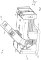
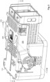
- FIGs. 1 to 3 show perspective views of a connector system 10 with a connector 100 and a mating connector 200.
- Fig. 1 is a perspective view of a connector system 10 with a latching element 300 in a disengaged position.
- Fig. 2 is a perspective view of the connector system of Fig. 1 with a latching element in a latched position and a CPA 400 in an open position.
- Fig. 3 is a perspective view of the connector system of Fig. 2 , with the CPA 400 in a locked position.
- the connector 100 has a housing 110, the housing 110 extending in a mating direction 20 between a mating connector end 112, to which the mating connector 200 is connected in Figures 1 to 3 , and an opposite connector end 114.
- a mating connector receptacle of the connector 100 is completely filled by the mating connector 200.
- the housing 110 has an outer surface and an opposite inner surface.
- the inner surface encloses an inner space, whereby the inner space is used to contact lines of the connector with lines of the mating connector.
- the housing 110 has side walls that run parallel to the mating direction 20.
- the side walls parallel to the mating direction include a cable side wall 116 having a cable area for routing lines out of the connector 100.
- the housing 110 has a first lever contact wall 118 having a latching area for arranging the latching element 300.
- Hidden in the perspective view are a rear side wall opposite the cable side wall 116 and a second lever contact wall opposite the first lever contact wall.
- the connector end 114 is thus a housing region of the connector 200 that is remote from the mating connector end 112, as it is opposite thereto.
- the latching element 300 is arranged at least partially at the connector end 114 of the housing, namely a handle 310 rests against the connector end 114 in the latched position.
- the handle 310 is for actuation by a user.
- the latching element is arranged to also assume a disengaged position and can be moved into the latched position shown in Figs. 2 and 3 , for example by a user.
- the latching element 300 may be a lever, the lever being rotatably mounted for movement about a lever axis 30 perpendicular to the mating direction 20 so that the lever is movable between the disengaged position and the latched position.
- the connector 100 includes connector position assurance (CPA) 400 for securing the contact position, which is provided at the connector end 114.
- CPA connector position assurance
- the CPA 400 may be in an open position in which the connector and the mating connector are separable.
- the CPA 400 may be in a locked position in which the connector and the mating connector are locked.
- FIG. 4 is a sectional view corresponding to the connector system of Fig. 2 along the line V-V, whereby, unlike in Fig. 2 , the connector 100 and the mating connector 200 are not connected. Thus, the locked position of the CPA is not released.
- the mating connector receptacle 102 provided at the mating connector end 112 of the connector 100 does not fully receive the mating connector 200.
- the connector 100 and the mating connector 200 are therefore not correctly connected. In particular, this can happen even though the latching element 300 is in the engaged position shown in Figures 2 and 3 .
- Fig. 5 shows a sectional view of the connector system along the sectional axis V-V of Fig. 2 .
- the connector 100 and the mating connector 200 are correctly connected.
- the transmission element 120 then enables the locked position of the CPA 400 to be released.
- the transmission element 120 extends along the mating direction 20.
- Fig. 4 shows the transmission element 120 in a disconnected position, in which the connector 100 and the mating connector 200 are disconnected.
- Fig. 5 shows the transmission element 120 in a mated position, in which the connector 100 and the mating connector 200 are connected.
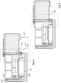
- Fig. 6 shows detail VI from Fig. 4 and Fig. 7 shows detail VII from Fig. 5 .
- the transmission element 120 is movably mounted in a channel 122 in the connector 100.
- the position of the transmission element 120 is fixed by the mating connector 200.
- the channel 122 may be provided insulated from a line not shown, for example a high-voltage electrical connection, in the housing.
- the transmission element 120 may be rod-shaped. It extends between a transmission element mating connector end 125 and a transmission element connector end 128.
- the rod is long in the mating direction 20 and narrow perpendicular to the mating direction 20.
- a mating connector passageway 124 is provided at the mating connector end 112 of the housing.
- the channel 122 is open to the mating connector receptacle 102 at the mating connector end 112.
- the mating connector passageway 124 allows the mating connector 200 to interact with the transmission element 124.
- the transmission element mating connector end 125 may protrude through the mating connector passageway 124, and may include a fixing element 125 at the transmission element mating connector end 124.
- the fixing element 124 protrudes perpendicular to the mating direction 20 to restrict the movement of the transmission element 120 in the mating direction 20. In Figures 6 and 7 , the fixing element 124 is perpendicular to the mating direction 20 and to the lever axis.
- the transmission element 120 may be in the disconnected position.
- the mating connector 200 is not in contact with the transmission element 120.
- the mating connector 200 is not fully received in the mating connector receptacle 102.
- the mating connector 200 does not contact the transmission element 120, in particular the transmission element mating connector end 124.
- the transmission element 120 can be in the mated position.
- the mating connector 200 and the connector 100 are correctly connected.
- the mating connector receptacle is filled by the mating connector 200.
- the mating connector is in contact with the transmission element 120, in particular the transmission element mating connector end 124.
- a connector end passageway 127 is provided at the connector end 114 of the housing.
- the channel 122 is open to the outer surface of the housing at the connector end 114.
- the connector end passageway 127 allows an unlocking element 129 to pass therethrough.
- the unlocking element 129 is connected to the transmission element 120.
- the unlocking element 129 is formed integrally with the transmission element 120.
- the unlocking element 129 prevents the CPA 400 from being movable into the locked position when the transmission element 120 is in the disconnected position.
- the transmission element connector end 128 here does not protrude from the housing at the connector end 114.
- the CPA 400 is not influenced by the unlocking element 129.
- the unlocking element 129 in the mated position of the transmission element 120 enables the CPA 400 to be moved into the locked position.
- the transmission element connector end 128 protrudes from the housing at the connector end 114, namely into the CPA 400.
- the CPA 400 is thus influenced by the unlocking element 129.
- Fig. 8 is a sectional view corresponding to the connector system of Fig. 2 along the line IX-IX, wherein the connector 100 and the mating connector 200 are not connected and the locked position of the CPA is not released. This means that the components are in the same position as described in Figures 4 and 6 .
- Fig. 9 shows a sectional view of the connector system along the sectional axis IX-IX of Fig. 2 , with the connector 100 and the mating connector 200 correctly connected.
- the transmission element 129 allows the locked position of the CPA to be released. This means that the components are in the same position as described in Figures 5 and 7 .
- the CPA is arranged in the handle 310.
- the handle 310 has a handle passageway 311, wherein the unlocking element 129 can be passed through the handle passageway 311.
- the handle passageway 311 aligns with the connector passage when the latching element 300 is in the engaged position so that the unlocking element 129 is passable.
- the CPA has a locking element 410 for interacting with the unlocking element 129.
- Fig. 8 shows the locking element 410 in a not-release position.
- Fig. 9 shows the locking element 410 in a release position. As shown in Fig. 9 , the unlocking element 129 moves the locking element 410 from the not-release position and the release position.
- the unlocking element 129 To enable the unlocking element 129 to move the locking element 410 perpendicular to the connector direction from a not-release position to a release position, the unlocking element has a chamfered edge 130.
- this arrangement enables the CPA at the connector end to be movable perpendicular to the mating direction between the open position and the locked position.
- the CPA comprises a block element 420.
- the block element 420 is connected to the handle 310 via the CPA. As shown in Figures 8 to 10 , the block element 420 protrudes in the mating direction when the latching element is in the latched position.
- the block element 420 blocks movement of the CPA to the locked position when the transmission element is in the disconnected position, so here the unlocking element 129 does not protrude into the CPA.
- the block element 420 does not block a movement of the CPA to the locked position when the transmission element is in the mated position, thus here the unlocking element 129 protrudes into the CPA.
- the locking element 410 is therefore in the release position and movement of the CPA into the locked position, shown in Fig. 10 , is possible.
- the connector comprises an engagement element 140 at the connector end, as shown in Fig. 9 .
- the CPA comprises a corresponding counter-engagement 440.
- the engagement element 140 and the counter-engagement 440 have grooves that are perpendicular to the mating direction.
- the engagement element 140 and the mating engagement 440 interact in the locked position of the CPA such that the connector is locked to the mating connector.
- the handle 310 can no longer be moved to the disengaged position. A user must consciously move the CPA back from the locked position to the open position.
- the fixing element 126 and a counter-fixing element 126' restrict the movement of the transmission element between the mated and disconnected position.
- the transmission element and the housing are non-detachably connected.
- the unlocking element does not necessarily have to be integrally formed with the transmission element. It can also be part of the CPA.
- the mating connector may comprise a pin header or be a pin header.
- connector system 20 mating direction 30 lever axis 100 connector 102 mating connector receptacle 110 housing 112 mating connector end 114 connector end 116 cable side panel 118 lever system wall 120 transmission element 122 channel 124 mating connector passageway 125 transmission element mating connector end 126 fixing element 126' counter fixing element 127 connector end passageway 128 transmission element connector end 129 unlocking element 130 chamfered edge 140 engagement element 200 mating connector 300 latching element 310 handle 311 handle passageway 400 CPA 410 locking element 420 block element
Landscapes
- Details Of Connecting Devices For Male And Female Coupling (AREA)
Abstract
The subject matter relates to a connector (100) for connecting to a mating connector (200). In particular, the connector comprises a transmission element (120) which extends along a mating direction (20) and is mounted movably with respect to the housing (110) of the connector between a mated position, in which the connector (100) and the mating connector (200) are connected, and a disconnected position, in which the connector (100) and the mating connector (200) are disconnected. In the disconnected position of the transmission element (120), an unlocking element (129) prevents a CPA (400) from being movable into the locked position. In a mated position of the transmission element (120), the unlocking element (129) allows the CPA (400) to be movable into the locked position.
Description
- The subject matter described herein generally relates to a connector with a connector position assurance (CPA). In particular, the subject matter relates to a connector for connecting to a mating connector, for example a pin header. Such connectors are used in particular for high-voltage connections, such as those required in the automotive industry.
- CPAs are designed to interlock, for example wedge, connectors and mating connectors that are correctly connected. Interlocking is an intentional and sometimes necessary blocking. The CPA is moved from an open position to a locked position by actuation, for example by a user. In an open position of the CPA, the connector and the mating connector are separable. In a locked position, the connector and the mating connector are locked.
- In CPAs, a coupling mechanism is used when a connector is connected to a mating connector to hold the connector and mating connector together when a conductive connector connection is formed. The coupling mechanism is designed to withstand forces in the locked position of the CPA that would pull the connector and mating connector apart and break the connection.
- In the locked position of the CPA, unwanted conditions, such as an unsafe contact position between the connector and mating connector, can thus be prevented. It is also intended to prevent accidental actions that could cause damage. Deliberate action is usually required to release the interlock. An interlock is designed in such a way that it cannot be overridden accidentally. At the same time, however, the locking mechanism itself should not be (too easily) activated accidentally. The latter could give a false sense of security, for example that the connector and the mating connector are correctly connected, which they are not.
- To convey the information that the connector and the mating connector are correctly connected, CPAs can be installed close to a mating connector receptacle. For example, a CPA is arranged close to the connection point between the connector and mating connector. As long as the connector and the mating connector are not connected, the CPA cannot be moved into the locked position. Only a part of the mating connector that engages with the CPA when the connector and the mating connector are connected allows the CPA to move into the locked position.
- With some connectors, however, the available installation space prevents the CPA from being installed close to the mating connector receptacle. Communicating the information that the connector and the mating connector are correctly connected then requires more complicated measures or the information that the connector and the mating connector are correctly connected is not communicated.
- The task of the invention is to provide a connector with a CPA that provides information that the connector and the mating connector are correctly connected. Furthermore, it is a task that the CPA can be provided remotely from the mating connector receptacle. Further, it is a task to reduce the complexity to convey the information that the connector and the mating connector are correctly connected. Furthermore, for connectors that are large, for example because they provide a latching element, it is a task to convey the information that the connector and the mating connector are correctly connected. It is also a task that known connectors can be modified in such a way that they enable information that the connector and the mating connector are correctly connected to be conveyed without changing the installation space specifications for the known connectors.
- The above tasks are solved by the subject matter of the independent claim. Advantageous further developments are the subject of the dependent patent claims.
- The tasks are solved in that a transmission element, for example an unlocking rod, is mounted in the connector. The transmission element moves when a mating connector, for example a header, is connected to a connector. This is possible because the transmission element interacts with the mating connector so that the transmission element is moved from a disconnected position to a mated position when the mating connector and the connector are connected. Thus, the transmission element conveys the information to the connector that the connector and the mating connector are correctly connected. When the connector and mating connector are fully mated, a CPA is unlocked, i.e. when the transmission element is moved to its maximum position, and it is then possible to move the CPA. The transmission element thus interacts with both the mating connector and the CPA, thereby enabling a CPA to be moved to a locked position only when the connector and mating connector are correctly connected.
- Detailed aspects of the connector with a CPA described herein are detailed below.
- A first aspect relates to a connector for connecting to a mating connector. A connector and a mating connector are connecting parts and together form a connector system. The connector system is used in particular for separating and connecting electrical lines, but also lines for optical signals, for example. The connecting parts can be aligned appropriately by form-fitting the connecting parts.
- The connector of the first aspect comprises a housing. The housing serves to accommodate the lines. The connector and the mating connector are movable relative to each other in a mating direction in order to fit the connecting parts together. Typically, the mating direction is identical to the orientation of pin contacts, which are arranged, for example, on the connector or the mating connector.
- The housing of the connector includes a mating connector receptacle at one mating connector end. The mating connector receptacle enables the connector to form a positive fit with the mating connector.
- Furthermore, the housing extends in the connector direction to a connector end opposite the mating connector end. In other words, the connector end is a housing area of the connector that is remote from the mating connector end. This makes it possible to provide installation space for further components of the connector between the connector end and the mating connector end. There are side walls between the connector end and the mating connector end that run parallel to the mating direction. The side walls provide installation space, for example for a cable area for routing lines out of the connector. The side walls can also provide installation space for a latching area for arranging a latching element.
- The connector of the first aspect comprises a connector position assurance (CPA) for securing the contact position of the connector to the mating connector. The CPA is provided at the connector end. In other words, the CPA is provided remote from the mating connector end. This makes it possible to fulfill space-related requirements between the CPA and the mating connector receptacle, i.e. on a side wall. Providing a connector with a CPA at the connector end allows a common part to be used for different size variants of connectors.
- The CPA, as already described above, is adapted to be movable between an open position, in which the connector and the mating connector are separable, and a locked position, in which the connector and the mating connector are locked.
- The connector of the first aspect comprises at least one transmission element or also a plurality of transmission elements. The transmission element is provided in and/or on the housing. Thus, an existing connector can be modified without changing installation space specifications for a connector if the transmission element does not protrude beyond a housing circumference. In particular, all interface contours of known connectors can remain the same. The transmission element can be realized as a simple part, for example as a rod, and can be easily installed in existing housings, possibly with a conversion kit. A rod is understood here in particular as a narrow, long, especially inelastic object with, for example, a round or approximately square cross-section.
- The transmission element extends along the mating direction. Thus, the transmission element can convey information along the mating direction as to whether the connector and the mating connector are correctly connected. Furthermore, the transmission element is mounted movably with respect to the housing between a mated position, in which the connector and the mating connector are connected, and a disconnected position, in which the connector and the mating connector are disconnected. The bearing allows the transmission element, which is movable relative to the housing, to move in a guide. For example, the transmission element is movably mounted in a channel as a guide for the housing. A channel is a tube, for example. A tube is an elongated hollow body whose length is usually significantly greater than its diameter.
- The connector of the first aspect further comprises a mating connector passageway at the mating connector end of the housing. The mating connector passageway is adapted to allow the mating connector to cooperate with the transmission element.
- In other words, a movement of the mating connector in the mating direction causes a movement of the transmission element. For example, the mating connector passageway is a passageway that allows at least a portion of the transmission element to protrude out of the guide in the mating direction through the mating connector passageway and/or allows at least a portion of the mating connector to protrude into the guide in the mating direction through the mating connector passageway. The mating connector passageway is further arranged to move the transmission element from the disconnected position to the mated position when the mating connector is connected to the connector. Thus, the transmission element can transmit information as to whether the connector and the mating connector are correctly connected as soon as the connector and the mating connector are connected or disconnected.
- The connector of the first aspect further comprising a connector end passageway at the connector end of the housing for passing an unlocking element connected to the transmission element. For example, the unlocking element is an unlocking end of the transmission element. Alternatively, the unlocking element is an unlocking part of the CPA.
- In the disconnected position of the transmission element, the unlocking element prevents the CPA from being movable into the locked position. For example, an unlocking end does not protrude through the connector end passageway, but is recessed in the guide. Alternatively, an unlocking part of the CPA can protrude through the connector end passageway.
- In the mated position of the transmission element, the unlocking element allows the CPA to be moved into the locked position. For example, the unlocking end protrudes through the connector end passageway. Alternatively, an unlocking part of the CPA may not protrude through the connector end passageway. Thus, the transmission element can pass information on whether the connector and the mating connector are correctly connected as soon as the connector and the mating connector are connected or disconnected to the CPA by means of a mechanical movement.
- A second aspect relates to a connector of the first aspect, wherein the connector comprises a locking element at the connector end. A locking element may be provided on the CPA or on an outer surface of the connector. The locking element can be moved by the unlocking element between a not-release position and a release position, wherein the release position of the locking element allows the CPA to move to the locked position. For example, the locking element is a spring element that is deflected by a force transmitted by the unlocking element. The locking element is therefore more elastic than the unlocking element.
- In particular, the unlocking element and the locking element form a lock that holds the position of the movable locking element relative to the connector, for example a block element on the CPA or the connector, until the unlocking element is in the mated position. Advantageously, the locking element is attached to the CPA, as this minimizes modifications to the housing of the connector.
- A third aspect relates to a connector described above in the first to second aspects, wherein the connector comprises a block element at the connector end, the block element blocking movement of the CPA to the locked position when the transmission element is in the disconnected position. For example, a block element is provided on the CPA or on an outer surface of the connector. Advantageously, a locking element is provided on the CPA, as this minimizes modifications to the housing. For example, the block element can be used to interact with the locking element. The block element can block movement of the CPA to the locked position when the locking element is in a not-release position. For example, the block element protrudes from the connector end in the connecting direction of the mating direction, hereinafter referred to as the mating connection direction.
- A fourth aspect relates to a connector described above in the first to third aspects, wherein the connector comprises an engagement element at the connector end, the engagement element and the CPA in the locked position of the CPA locking the connector to the mating connector. In particular, the engagement element is provided on the housing and extends in the mating connection direction and the CPA comprises a counter-engagement to cooperate with the engagement element, wherein the counter-engagement extends in the mating disconnection direction, i.e. opposite to the mating connection direction. Further, the engagement element and the counter-engagement comprise grooves extending perpendicular to the mating direction.
- A fifth aspect relates to a connector described above in the first to fourth aspects, wherein the unlocking element comprises a chamfered edge. Thus, the unlocking element has a chamfered surface. The chamfered edge is adapted to move the locking element perpendicular to the mating direction from a not-release position to a release position. The chamfered edge allows the locking element to be moved perpendicular to the mating direction by the unlocking element, which enables a flat design of the CPA.
- A sixth aspect relates to a connector described above in the first to fifth aspects, further comprising a latching element, wherein the latching element is arranged at least partially at the connector end of the housing and is arranged to move the mating connector in the mating direction, i.e. in the mating connection direction, by moving it from a disengaged position to a latched position. A mechanical force can be transmitted by a latching element in order to connect the connector and mating connector. Attaching the latching element to the connector end allows the CPA to interact with a part of the latching element at the connector end. The latching element can be attached to the connector end to save space. Furthermore, a latching element enables the CPA to be used effectively in a particularly simple manner, i.e. without further mechanical components. Although the latching element can be closed when not inserted, the CPA cannot be moved and therefore remains locked. In particular, a locking element of the CPA is then not loaded with a mass.
- A seventh aspect relates to a connector according to the sixth aspect, wherein the latching element is a lever, wherein the lever is rotatably mounted for movement about a lever axis perpendicular to the mating direction, such that the lever is movable between the disengaged position and the latched position. A lever mechanism can reduce the available installation space on the side walls of the housing. Thus, a CPA located at the connector end enables a space-optimized solution. Furthermore, a lever enables a lever force to be used to connect the connector and mating connector.
- An eighth aspect relates to a connector described in the sixth and seventh aspects above, wherein the latching element comprises a handle, the handle abutting the connector end of the housing when the latching element is in the latched position. Attaching the handle of the latching element to the connector end enables the CPA to interact with the handle at the connector end. This means that the CPA can be used effectively in a particularly simple way, i.e. without further mechanical components, and the user can be signaled in a particularly simple way if the handle of the latching element is not actuated as intended, as the user would have to unlock the CPA by the handle.
- A ninth aspect relates to a connector according to the eighth aspect, wherein the CPA is arranged on the handle and the handle has a handle passageway, wherein the unlocking element can be passed through the handle passageway. Thus, the CPA can be arranged in a particularly space-saving manner and elements, such as a locking element of the second aspect, can be provided in the CPA.
- A tenth aspect relates to a connector as described above in the eighth to ninth aspects, wherein the connector comprises a locking element according to the second aspect and/or a block element according to the third aspect, wherein the locking element and/or the block element is arranged on the handle. For example, the block element may protrude in the mating direction when the latching element is in the latched position. A block element and a locking element on the CPA enable both parts to be manufactured in one unit, namely as part of the CPA, which simplifies manufacturing.
- An eleventh aspect relates to a connector described above in the first to tenth aspects, wherein the transmission element, which is for example rod-shaped, extends between a mating connector end and the connector end, wherein the mating connector end of the transmission element protrudes through the mating connector passageway and comprises a fixing element at the mating connector end, wherein the fixing element protrudes perpendicular to the mating direction to restrict movement of the transmission element in the mating direction. This allows the transmission element to be fixed in the housing of the connector. No further modification to the mating connector is required.
- A twelfth aspect relates to a connector described above in the first to eleventh aspects, wherein the CPA at the connector end is movable perpendicularly to the mating direction between the open position and the locked position. This enables the CPA to be constructed flat, which is enabled by the vertical movement of the CPA.
- A thirteenth aspect relates to a connector described above in the first to twelfth aspects, wherein the connector comprises a channel, wherein the transmission element is supported in the channel, and wherein the channel is provided insulated from a line in the housing. The channel with the transmission element is open to the environment through the passageways. The channel is the transmission path closed off in the housing from the connector end to the mating connector end of the housing. Solids such as dirt, fluids such as water or electromagnetic radiation such as optical light can penetrate from the outside. The insulation, for example electrical, hermetic, electromagnetic and/or optical insulation, makes the channel advantageous for high-voltage applications and/or applications in information transmission, for example, as the contact points can be particularly protected from external influences.
- A fourteenth aspect relates to a connector system comprising a connector described above in the first to thirteenth aspects, and a mating connector.
- A fifteenth aspect relates to a connector system according to the fourteenth aspect, wherein the mating connector comprises a pin header or is a pin header. A pin header without further devices with safety requirements can be connected to the connector here, as the connector already comprises a CPA. The mating connector can thus be simple, namely a pin header.
- A pin header is a mating connector with, for example, several pin contacts arranged in series. Its purpose is to establish a connection with many contacts from a mating connector to a connector.
- For a better understanding of the present invention, it is explained in more detail with reference to the embodiments shown in the following figures. The same parts are provided with the same reference signs and the same component designations. Furthermore, some features or combinations of features from the different embodiments shown and described may represent independent inventive solutions or solutions according to the invention.
- It shows:
- Fig. 1
- a perspective view of a connector system with a latching element in a disengaged position;
- Fig. 2
- a perspective view of the connector system from
Fig. 1 with a latching element in a latched position and a CPA in an open position; - Fig. 3
- a perspective view of the connector system from
Fig. 2 , with the CPA in a locked position; - Fig. 4
- a sectional view corresponding to the sectional axis V-V of the connector system in
Fig. 2 , where the connector and the mating connector are not connected and the locked position of the CPA is not released; - Fig. 5
- a sectional view of the connector system along the sectional axis V-V of
Fig. 2 , with the locked position of the CPA released; - Fig. 6
- a detail VI of
Fig. 4 ; - Fig. 7
- a detail VII of
Fig. 5 ; - Fig. 8
- a sectional view corresponding to the sectional axis IX-IX of the connector system of
Fig. 2 , whereby the connector and the mating connector are not connected and the locked position of the CPA is not released; - Fig. 9
- a sectional view of the connector system along the sectional axis IX-IX of
Fig. 2 , with the locked position of the CPA released; - Fig. 10
- a sectional view of the connector system of
Fig. 3 ; - Fig. 11
- a perspective view of
Fig. 5 ; and - Fig. 12
- a detail of
Fig. 11 . - The connector is now described with the help of the figures.
Figs. 1 to 3 show perspective views of aconnector system 10 with aconnector 100 and amating connector 200. -
Fig. 1 is a perspective view of aconnector system 10 with a latchingelement 300 in a disengaged position.Fig. 2 is a perspective view of the connector system ofFig. 1 with a latching element in a latched position and aCPA 400 in an open position.Fig. 3 is a perspective view of the connector system ofFig. 2 , with theCPA 400 in a locked position. - For example, as shown in
Fig. 1 , theconnector 100 has ahousing 110, thehousing 110 extending in amating direction 20 between amating connector end 112, to which themating connector 200 is connected inFigures 1 to 3 , and anopposite connector end 114. InFigures 1 to 3 , a mating connector receptacle of theconnector 100 is completely filled by themating connector 200. - The
housing 110 has an outer surface and an opposite inner surface. The inner surface encloses an inner space, whereby the inner space is used to contact lines of the connector with lines of the mating connector. - As shown, for example, in
Fig. 1 , thehousing 110 has side walls that run parallel to themating direction 20. Here, the side walls parallel to the mating direction include acable side wall 116 having a cable area for routing lines out of theconnector 100. Further, thehousing 110 has a firstlever contact wall 118 having a latching area for arranging the latchingelement 300. Hidden in the perspective view are a rear side wall opposite thecable side wall 116 and a second lever contact wall opposite the first lever contact wall. Theconnector end 114 is thus a housing region of theconnector 200 that is remote from themating connector end 112, as it is opposite thereto. - As shown in
Fig. 2 , the latchingelement 300 is arranged at least partially at theconnector end 114 of the housing, namely ahandle 310 rests against theconnector end 114 in the latched position. Thehandle 310 is for actuation by a user. As shown inFig. 1 , the latching element is arranged to also assume a disengaged position and can be moved into the latched position shown inFigs. 2 and3 , for example by a user. - As shown in
Figures 1 to 3 , the latchingelement 300 may be a lever, the lever being rotatably mounted for movement about alever axis 30 perpendicular to themating direction 20 so that the lever is movable between the disengaged position and the latched position. - Further, the
connector 100 includes connector position assurance (CPA) 400 for securing the contact position, which is provided at theconnector end 114. As shown inFig. 2 , theCPA 400 may be in an open position in which the connector and the mating connector are separable. Further, as shown inFig. 3 , theCPA 400 may be in a locked position in which the connector and the mating connector are locked. - A
transmission element 120 of theconnector 100 is first described in particular with reference toFigs. 4 and 5. Fig. 4 is a sectional view corresponding to the connector system ofFig. 2 along the line V-V, whereby, unlike inFig. 2 , theconnector 100 and themating connector 200 are not connected. Thus, the locked position of the CPA is not released. In particular, as shown inFig. 4 , themating connector receptacle 102 provided at themating connector end 112 of theconnector 100 does not fully receive themating connector 200. Theconnector 100 and themating connector 200 are therefore not correctly connected. In particular, this can happen even though the latchingelement 300 is in the engaged position shown inFigures 2 and3 . -
Fig. 5 then shows a sectional view of the connector system along the sectional axis V-V ofFig. 2 . Here, theconnector 100 and themating connector 200 are correctly connected. Thetransmission element 120 then enables the locked position of theCPA 400 to be released. - As shown in
Figures 4 and 5 , thetransmission element 120 extends along themating direction 20.Fig. 4 shows thetransmission element 120 in a disconnected position, in which theconnector 100 and themating connector 200 are disconnected.Fig. 5 shows thetransmission element 120 in a mated position, in which theconnector 100 and themating connector 200 are connected. -
Fig. 6 shows detail VI fromFig. 4 andFig. 7 shows detail VII fromFig. 5 . As can be seen inFigs. 6 and 7 , thetransmission element 120 is movably mounted in achannel 122 in theconnector 100. The position of thetransmission element 120 is fixed by themating connector 200. Thechannel 122 may be provided insulated from a line not shown, for example a high-voltage electrical connection, in the housing. - As shown here, the
transmission element 120 may be rod-shaped. It extends between a transmission elementmating connector end 125 and a transmissionelement connector end 128. The rod is long in themating direction 20 and narrow perpendicular to themating direction 20. - A
mating connector passageway 124 is provided at themating connector end 112 of the housing. In other words, thechannel 122 is open to themating connector receptacle 102 at themating connector end 112. Themating connector passageway 124 allows themating connector 200 to interact with thetransmission element 124. - The transmission element
mating connector end 125 may protrude through themating connector passageway 124, and may include a fixingelement 125 at the transmission elementmating connector end 124. The fixingelement 124 protrudes perpendicular to themating direction 20 to restrict the movement of thetransmission element 120 in themating direction 20. InFigures 6 and 7 , the fixingelement 124 is perpendicular to themating direction 20 and to the lever axis. - As shown in
Fig. 6 , thetransmission element 120 may be in the disconnected position. Themating connector 200 is not in contact with thetransmission element 120. In other words, themating connector 200 is not fully received in themating connector receptacle 102. In other words, themating connector 200 does not contact thetransmission element 120, in particular the transmission elementmating connector end 124. - As shown in
Fig. 7 , thetransmission element 120 can be in the mated position. Themating connector 200 and theconnector 100 are correctly connected. Thus, the mating connector receptacle is filled by themating connector 200. In other words, the mating connector is in contact with thetransmission element 120, in particular the transmission elementmating connector end 124. - A
connector end passageway 127 is provided at theconnector end 114 of the housing. In other words, thechannel 122 is open to the outer surface of the housing at theconnector end 114. Theconnector end passageway 127 allows an unlockingelement 129 to pass therethrough. The unlockingelement 129 is connected to thetransmission element 120. Here, the unlockingelement 129 is formed integrally with thetransmission element 120. - As shown in
Fig. 6 , and explained later with reference toFigs. 8 to 10 , the unlockingelement 129 prevents theCPA 400 from being movable into the locked position when thetransmission element 120 is in the disconnected position. In particular, the transmissionelement connector end 128 here does not protrude from the housing at theconnector end 114. TheCPA 400 is not influenced by the unlockingelement 129. - As shown in
Fig. 7 , and explained later withFigs. 8 to 10 , the unlockingelement 129 in the mated position of thetransmission element 120 enables theCPA 400 to be moved into the locked position. Here, the transmissionelement connector end 128 protrudes from the housing at theconnector end 114, namely into theCPA 400. TheCPA 400 is thus influenced by the unlockingelement 129. - The CPA of the
connector 100 is now described in particular withFigs. 8 to 10. Fig. 8 is a sectional view corresponding to the connector system ofFig. 2 along the line IX-IX, wherein theconnector 100 and themating connector 200 are not connected and the locked position of the CPA is not released. This means that the components are in the same position as described inFigures 4 and6 . -
Fig. 9 shows a sectional view of the connector system along the sectional axis IX-IX ofFig. 2 , with theconnector 100 and themating connector 200 correctly connected. Thetransmission element 129 allows the locked position of the CPA to be released. This means that the components are in the same position as described inFigures 5 and7 . - In
Figures 8 to 10 , the CPA is arranged in thehandle 310. Thehandle 310 has ahandle passageway 311, wherein the unlockingelement 129 can be passed through thehandle passageway 311. In particular, thehandle passageway 311 aligns with the connector passage when the latchingelement 300 is in the engaged position so that the unlockingelement 129 is passable. - In particular, the CPA has a
locking element 410 for interacting with the unlockingelement 129.Fig. 8 shows the lockingelement 410 in a not-release position.Fig. 9 shows the lockingelement 410 in a release position. As shown inFig. 9 , the unlockingelement 129 moves the lockingelement 410 from the not-release position and the release position. - To enable the unlocking
element 129 to move thelocking element 410 perpendicular to the connector direction from a not-release position to a release position, the unlocking element has a chamferededge 130. Thus, this arrangement enables the CPA at the connector end to be movable perpendicular to the mating direction between the open position and the locked position. - Further, the CPA comprises a
block element 420. Theblock element 420 is connected to thehandle 310 via the CPA. As shown inFigures 8 to 10 , theblock element 420 protrudes in the mating direction when the latching element is in the latched position. - As shown in
Fig. 8 , theblock element 420 blocks movement of the CPA to the locked position when the transmission element is in the disconnected position, so here the unlockingelement 129 does not protrude into the CPA. As shown inFig. 9 , theblock element 420 does not block a movement of the CPA to the locked position when the transmission element is in the mated position, thus here the unlockingelement 129 protrudes into the CPA. The lockingelement 410 is therefore in the release position and movement of the CPA into the locked position, shown inFig. 10 , is possible. - Furthermore, the connector comprises an
engagement element 140 at the connector end, as shown inFig. 9 . The CPA comprises acorresponding counter-engagement 440. Theengagement element 140 and the counter-engagement 440 have grooves that are perpendicular to the mating direction. - As shown in
Fig. 10 , theengagement element 140 and themating engagement 440 interact in the locked position of the CPA such that the connector is locked to the mating connector. In particular, thehandle 310 can no longer be moved to the disengaged position. A user must consciously move the CPA back from the locked position to the open position. -
Fig. 11 is a further perspective view ofFig. 5 .Fig. 12 shows detail XII ofFig. 11 . In particular, it can be seen fromFig. 12 that theblock element 420 can be manufactured in one piece with thehandle 310. The lockingelement 410 can also be manufactured in one piece with thehandle 310. - Furthermore, it can be seen that the
CPA 400 comprises a finger actuation unit for easily moving the CPA by a user's finger. Here, theCPA 400 may also be non-detachably connected to thehandle 310. Non-detachably connected means that the two components cannot be disconnected without the use of force thereby for example destroying the pieces. - Furthermore, it can be seen that the fixing
element 126 and a counter-fixing element 126' restrict the movement of the transmission element between the mated and disconnected position. In particular, the transmission element and the housing are non-detachably connected. - Even if not shown in the figures, the latching element does not necessarily have to be provided. Furthermore, an alternative latching element such as a sliding element can also be provided as a latching element instead of a lever as a latching element.
- Even if not shown in the figures, the unlocking element does not necessarily have to be integrally formed with the transmission element. It can also be part of the CPA.
- Although not shown in the figures, the mating connector may comprise a pin header or be a pin header.
-
Reference number Description 10 connector system 20 mating direction 30 lever axis 100 connector 102 mating connector receptacle 110 housing 112 mating connector end 114 connector end 116 cable side panel 118 lever system wall 120 transmission element 122 channel 124 mating connector passageway 125 transmission element mating connector end 126 fixing element 126' counter fixing element 127 connector end passageway 128 transmission element connector end 129 unlocking element 130 chamfered edge 140 engagement element 200 mating connector 300 latching element 310 handle 311 handle passageway 400 CPA 410 locking element 420 block element
Claims (15)
- Connector for connecting to a mating connector (200), the connector (100) comprising:a housing (110), wherein the housing (110) extends in a mating direction (20) between a mating connector end (112) for connection to the mating connector (200) and an opposite connector end (114),a connector position assurance, CPA, (400) for securing the contact position of the connector (100) on the mating connector (200), wherein the CPA (400) is provided at the connector end (114) and wherein the CPA (400) is adapted to be movable between an open position, in which the connector (100) and the mating connector (200) are separable, and a locked position, in which the connector (100) and the mating connector (200) are locked,a transmission element (120) which extends along the mating direction (20) and is mounted movably relative to the housing (110) between a mated position, in which the connector (100) and the mating connector (200) are connected, and a disconnected position, in which the connector (100) and the mating connector (200) are disconnected,a mating connector passageway (124) at the mating connector end (112) of the housing (110), the mating connector passageway (124) being arranged to cause the mating connector (200) to cooperate with the transmission element (120) so that the transmission element (120) is moved from the disconnected position to the mated position when the mating connector (200) and the connector (100) are connected,a connector end passageway (127) at the connector end (114) of the housing (110) for passing an unlocking element (129) connected to the transmission element (120), wherein in the disconnected position of the transmission element (120), the unlocking element (129) prevents the CPA (400) from being movable to the locked position, and wherein in the mated position of the transmission element (120), the unlocking element (129) allows the CPA (400) to be movable to the locked position.
- Connector (100) according to claim 1, wherein the connector (100) comprises a locking element (410) at the connector end (114) for cooperating with the unlocking element (129), wherein the locking element (410) is movable by the unlocking element (129) between a not-release position and a release position, wherein the release position of the locking element (410) enables the movement of the CPA (400) into the locked position.
- Connector (100) according to any one of claims 1 to 2, wherein the connector (100) comprises a block element (420) at the connector end (114), wherein the block element (420) blocks a movement of the CPA (400) to the locked position when the transmission element (120) is in the disconnected position.
- Connector (100) according to any one of claims 1 to 3, wherein the connector (100) comprises an engagement element (140) at the connector end (114), wherein the engagement element (140) and the CPA (400) lock the connector (100) to the mating connector (200) in the locked position of the CPA (400).
- Connector (100) according to any one of claims 1 to 4, wherein the unlocking element (129) comprises a chamfered edge (130), wherein the chamfered edge (130) is adapted to move a locking element (410) perpendicular to the mating direction (20) from a not-release position to a release position.
- Connector (100) according to any one of claims 1 to 5, further comprising a latching element (300), wherein the latching element (300) is arranged at least partially at the connector end (114) of the housing (110) and is arranged to move the mating connector (200) in the mating direction (20) by moving it from a disengaged position to a latched position.
- Connector (100) according to claim 6, wherein the latching element (300) is a lever, wherein the lever is rotatably mounted movably about a lever axis (30) perpendicular to the mating direction (20), so that the lever is movable between the disengaged position and the latched position.
- Connector (100) according to any one of claims 6 to 7, wherein the latching element (300) comprises a handle (310), wherein the handle (310) abuts against the connector end (114) of the housing (110) in the latched position of the latching element (300).
- Connector (100) according to claim 8, wherein the CPA (400) is arranged on the handle (310) and the handle (310) has a handle passageway (311), wherein the unlocking element (129) can be passed through the handle passageway (311).
- Connector (100) according to any one of claims 8 to 9, comprising a locking element (410) according to claim 2 and/or a block element (420) according to claim 3, wherein at least one of the locking element (410) and the block element (410) is arranged on the handle (310) and protrudes in the mating direction (20) in the latched position of the latching element (300).
- Connector (100) according to any one of claims 1 to 10, wherein the transmission element (120) extends between a transmission element mating connector end (125) and a transmission element connector end (128), wherein the transmission element mating connector end (125) protrudes through the mating connector passageway (124) and comprises a fixing element (126) at the transmission element mating connector end (125), wherein the fixing element (126) protrudes perpendicular to the mating direction (20) to restrict the movement of the transmission element (120) in the mating direction (20).
- Connector (100) according to any one of claims 1 to 11, wherein the CPA (400) at the connector end (114) is movable perpendicular to the mating direction (20) between the open position and the locked position.
- Connector (100) according to any one of claims 1 to 12, wherein the connector (100) comprises a channel (122), wherein the transmission element (120) is supported in the channel (122), and wherein the channel (122) is provided insulated from a line in the housing (110).
- Connector system (10) comprising a connector (100) according to any one of claims 1 to 13 and a mating connector (200).
- Connector system (10) according to claim 14, wherein the mating connector (200) comprises a pin header.
Applications Claiming Priority (1)
| Application Number | Priority Date | Filing Date | Title |
|---|---|---|---|
| DE102023103379.4A DE102023103379A1 (en) | 2023-02-13 | 2023-02-13 | Connector with a Connector Position Assurance |
Publications (1)
| Publication Number | Publication Date |
|---|---|
| EP4415184A1 true EP4415184A1 (en) | 2024-08-14 |
Family
ID=89900924
Family Applications (1)
| Application Number | Title | Priority Date | Filing Date |
|---|---|---|---|
| EP24156975.5A Pending EP4415184A1 (en) | 2023-02-13 | 2024-02-12 | Connector with connector position assurance |
Country Status (6)
| Country | Link |
|---|---|
| US (1) | US12700697B2 (en) |
| EP (1) | EP4415184A1 (en) |
| JP (1) | JP7715473B2 (en) |
| KR (1) | KR102942076B1 (en) |
| CN (1) | CN118487074A (en) |
| DE (1) | DE102023103379A1 (en) |
Citations (2)
| Publication number | Priority date | Publication date | Assignee | Title |
|---|---|---|---|---|
| US20040192090A1 (en) * | 2003-03-28 | 2004-09-30 | Flowers Robert J. | Lever type electrical connector with CPA member |
| EP4012847A1 (en) * | 2020-12-10 | 2022-06-15 | TE Connectivity Germany GmbH | Electrical plug device with a blocking mechanism for a position assurance element which can be released by a mating housing |
Family Cites Families (11)
| Publication number | Priority date | Publication date | Assignee | Title |
|---|---|---|---|---|
| JP3419715B2 (en) | 1999-10-14 | 2003-06-23 | 株式会社オートネットワーク技術研究所 | Lock mechanism in connector |
| DE10032234B4 (en) * | 2000-07-03 | 2005-04-07 | Fci Automotive Deutschland Gmbh | Connector with secondary locking |
| US6716052B2 (en) * | 2002-02-21 | 2004-04-06 | Tyco Electronics Corporation | Connector position assurance device and latch |
| US6705886B1 (en) * | 2003-01-23 | 2004-03-16 | Fci Americas Technology, Inc. | Electrical connector having connector position assurance member |
| US7351089B2 (en) * | 2006-04-28 | 2008-04-01 | Delphi Technologies, Inc. | Electrical connector having a CPA plug |
| US8784127B2 (en) * | 2012-06-11 | 2014-07-22 | Delphi Technologies, Inc. | Electrical connection system including mating assist lever that contains locking means and connector position assurance member that interacts therewith |
| FR3049778A1 (en) * | 2016-03-30 | 2017-10-06 | Tyco Electronics France Sas | ELECTRICAL CONNECTOR WITH ROTATING CONNECTOR POSITION ASSURANCE DEVICE |
| KR102478092B1 (en) | 2017-10-17 | 2022-12-16 | 현대자동차주식회사 | Female terminal |
| JP6940543B2 (en) | 2019-03-15 | 2021-09-29 | 矢崎総業株式会社 | Lever type connector |
| DE102021112425A1 (en) | 2021-05-12 | 2022-11-17 | Te Connectivity Germany Gmbh | Vibration resistant high current electrical flat socket contact device |
| DE102022118880A1 (en) | 2022-07-27 | 2024-02-01 | Te Connectivity Germany Gmbh | Connector arrangement |
-
2023
- 2023-02-13 DE DE102023103379.4A patent/DE102023103379A1/en active Pending
-
2024
- 2024-02-07 JP JP2024016840A patent/JP7715473B2/en active Active
- 2024-02-08 KR KR1020240019399A patent/KR102942076B1/en active Active
- 2024-02-08 CN CN202410177611.7A patent/CN118487074A/en active Pending
- 2024-02-12 EP EP24156975.5A patent/EP4415184A1/en active Pending
- 2024-02-12 US US18/439,065 patent/US12700697B2/en active Active
Patent Citations (2)
| Publication number | Priority date | Publication date | Assignee | Title |
|---|---|---|---|---|
| US20040192090A1 (en) * | 2003-03-28 | 2004-09-30 | Flowers Robert J. | Lever type electrical connector with CPA member |
| EP4012847A1 (en) * | 2020-12-10 | 2022-06-15 | TE Connectivity Germany GmbH | Electrical plug device with a blocking mechanism for a position assurance element which can be released by a mating housing |
Also Published As
| Publication number | Publication date |
|---|---|
| US20240275106A1 (en) | 2024-08-15 |
| KR102942076B1 (en) | 2026-03-19 |
| US12700697B2 (en) | 2026-08-04 |
| KR20240126421A (en) | 2024-08-20 |
| JP7715473B2 (en) | 2025-07-30 |
| CN118487074A (en) | 2024-08-13 |
| DE102023103379A1 (en) | 2024-08-14 |
| JP2024114646A (en) | 2024-08-23 |
Similar Documents
| Publication | Publication Date | Title |
|---|---|---|
| US9929509B1 (en) | Connector system with low profile connector position assurance device | |
| EP0726617B1 (en) | Connector with secondary locking and coupling mechanism | |
| EP2700130B1 (en) | Airbag connector system | |
| CN103053082B (en) | There is the electric connector of shell body, inner housing and instruction sleeve | |
| EP3392979B1 (en) | Electrical connector with lever and methods of assembling thereof | |
| CA2799290C (en) | Plug-type connector with a radially acting latching device | |
| KR20200056279A (en) | Coupling connector comprising a slider part | |
| US9059540B2 (en) | Electrical connector assembly, and connector for such assembly | |
| CN104904074B (en) | There is the connector assembly of automatic auxiliary lock | |
| CN109863649A (en) | It is electrically interposed in formula connector | |
| JP6500112B2 (en) | Intermediate housing comprising a CPA receiving member and plug-type connector system comprising such a housing | |
| US20150270644A1 (en) | Electrical Connector And Assembly Therewith Having A Spring-Apart Function | |
| US6149473A (en) | Connector with secondary locking and coupling mechanism | |
| CN115995727A (en) | Plug connectors for connecting signal conductors | |
| CN215579305U (en) | Plug connector part of a plug connection | |
| US11888254B2 (en) | Connector assembly comprising module with integrated terminal position assurance means | |
| US11855380B2 (en) | Adapter, plug connector assembly and connector assembly | |
| US20240275106A1 (en) | Connector with connector position assurance | |
| EP4228105A1 (en) | Coding clip, plug assembly and connector assembly | |
| EP4228106A1 (en) | Connector | |
| US20220360017A1 (en) | Connection system for connecting signal conductors | |
| KR20240015602A (en) | Connector assembly | |
| US20260066581A1 (en) | Electrical connector and electrical connector assembly | |
| KR101632704B1 (en) | Connector assembly | |
| US20260066580A1 (en) | Electrical connector and electrical connector assembly |
Legal Events
| Date | Code | Title | Description |
|---|---|---|---|
| PUAI | Public reference made under article 153(3) epc to a published international application that has entered the european phase |
Free format text: ORIGINAL CODE: 0009012 |
|
| STAA | Information on the status of an ep patent application or granted ep patent |
Free format text: STATUS: THE APPLICATION HAS BEEN PUBLISHED |
|
| AK | Designated contracting states |
Kind code of ref document: A1 Designated state(s): AL AT BE BG CH CY CZ DE DK EE ES FI FR GB GR HR HU IE IS IT LI LT LU LV MC ME MK MT NL NO PL PT RO RS SE SI SK SM TR |
|
| STAA | Information on the status of an ep patent application or granted ep patent |
Free format text: STATUS: REQUEST FOR EXAMINATION WAS MADE |
|
| 17P | Request for examination filed |
Effective date: 20250110 |