EP4415160A1 - Lamp device - Google Patents
Lamp device Download PDFInfo
- Publication number
- EP4415160A1 EP4415160A1 EP22895234.7A EP22895234A EP4415160A1 EP 4415160 A1 EP4415160 A1 EP 4415160A1 EP 22895234 A EP22895234 A EP 22895234A EP 4415160 A1 EP4415160 A1 EP 4415160A1
- Authority
- EP
- European Patent Office
- Prior art keywords
- lamp device
- electromagnetic wave
- base layer
- reflector
- resin member
- Prior art date
- Legal status (The legal status is an assumption and is not a legal conclusion. Google has not performed a legal analysis and makes no representation as to the accuracy of the status listed.)
- Granted
Links
Images


Classifications
-
- F—MECHANICAL ENGINEERING; LIGHTING; HEATING; WEAPONS; BLASTING
- F21—LIGHTING
- F21S—NON-PORTABLE LIGHTING DEVICES; SYSTEMS THEREOF; VEHICLE LIGHTING DEVICES SPECIALLY ADAPTED FOR VEHICLE EXTERIORS
- F21S45/00—Arrangements within vehicle lighting devices specially adapted for vehicle exteriors, for purposes other than emission or distribution of light
-
- B—PERFORMING OPERATIONS; TRANSPORTING
- B60—VEHICLES IN GENERAL
- B60Q—ARRANGEMENT OF SIGNALLING OR LIGHTING DEVICES, THE MOUNTING OR SUPPORTING THEREOF OR CIRCUITS THEREFOR, FOR VEHICLES IN GENERAL
- B60Q1/00—Arrangement of optical signalling or lighting devices, the mounting or supporting thereof or circuits therefor
- B60Q1/0017—Devices integrating an element dedicated to another function
- B60Q1/0023—Devices integrating an element dedicated to another function the element being a sensor, e.g. distance sensor, camera
-
- B—PERFORMING OPERATIONS; TRANSPORTING
- B60—VEHICLES IN GENERAL
- B60Q—ARRANGEMENT OF SIGNALLING OR LIGHTING DEVICES, THE MOUNTING OR SUPPORTING THEREOF OR CIRCUITS THEREFOR, FOR VEHICLES IN GENERAL
- B60Q1/00—Arrangement of optical signalling or lighting devices, the mounting or supporting thereof or circuits therefor
- B60Q1/02—Arrangement of optical signalling or lighting devices, the mounting or supporting thereof or circuits therefor the devices being primarily intended to illuminate the way ahead or to illuminate other areas of way or environments
- B60Q1/04—Arrangement of optical signalling or lighting devices, the mounting or supporting thereof or circuits therefor the devices being primarily intended to illuminate the way ahead or to illuminate other areas of way or environments the devices being headlights
-
- F—MECHANICAL ENGINEERING; LIGHTING; HEATING; WEAPONS; BLASTING
- F21—LIGHTING
- F21S—NON-PORTABLE LIGHTING DEVICES; SYSTEMS THEREOF; VEHICLE LIGHTING DEVICES SPECIALLY ADAPTED FOR VEHICLE EXTERIORS
- F21S41/00—Illuminating devices specially adapted for vehicle exteriors, e.g. headlamps
- F21S41/10—Illuminating devices specially adapted for vehicle exteriors, e.g. headlamps characterised by the light source
- F21S41/14—Illuminating devices specially adapted for vehicle exteriors, e.g. headlamps characterised by the light source characterised by the type of light source
- F21S41/141—Light emitting diodes [LED]
- F21S41/147—Light emitting diodes [LED] the main emission direction of the LED being angled to the optical axis of the illuminating device
- F21S41/148—Light emitting diodes [LED] the main emission direction of the LED being angled to the optical axis of the illuminating device the main emission direction of the LED being perpendicular to the optical axis
-
- F—MECHANICAL ENGINEERING; LIGHTING; HEATING; WEAPONS; BLASTING
- F21—LIGHTING
- F21S—NON-PORTABLE LIGHTING DEVICES; SYSTEMS THEREOF; VEHICLE LIGHTING DEVICES SPECIALLY ADAPTED FOR VEHICLE EXTERIORS
- F21S41/00—Illuminating devices specially adapted for vehicle exteriors, e.g. headlamps
- F21S41/10—Illuminating devices specially adapted for vehicle exteriors, e.g. headlamps characterised by the light source
- F21S41/19—Attachment of light sources or lamp holders
-
- F—MECHANICAL ENGINEERING; LIGHTING; HEATING; WEAPONS; BLASTING
- F21—LIGHTING
- F21S—NON-PORTABLE LIGHTING DEVICES; SYSTEMS THEREOF; VEHICLE LIGHTING DEVICES SPECIALLY ADAPTED FOR VEHICLE EXTERIORS
- F21S41/00—Illuminating devices specially adapted for vehicle exteriors, e.g. headlamps
- F21S41/30—Illuminating devices specially adapted for vehicle exteriors, e.g. headlamps characterised by reflectors
- F21S41/32—Optical layout thereof
- F21S41/321—Optical layout thereof the reflector being a surface of revolution or a planar surface, e.g. truncated
-
- F—MECHANICAL ENGINEERING; LIGHTING; HEATING; WEAPONS; BLASTING
- F21—LIGHTING
- F21S—NON-PORTABLE LIGHTING DEVICES; SYSTEMS THEREOF; VEHICLE LIGHTING DEVICES SPECIALLY ADAPTED FOR VEHICLE EXTERIORS
- F21S41/00—Illuminating devices specially adapted for vehicle exteriors, e.g. headlamps
- F21S41/30—Illuminating devices specially adapted for vehicle exteriors, e.g. headlamps characterised by reflectors
- F21S41/32—Optical layout thereof
- F21S41/33—Multi-surface reflectors, e.g. reflectors with facets or reflectors with portions of different curvature
- F21S41/334—Multi-surface reflectors, e.g. reflectors with facets or reflectors with portions of different curvature the reflector consisting of patch like sectors
- F21S41/336—Multi-surface reflectors, e.g. reflectors with facets or reflectors with portions of different curvature the reflector consisting of patch like sectors with discontinuity at the junction between adjacent areas
-
- F—MECHANICAL ENGINEERING; LIGHTING; HEATING; WEAPONS; BLASTING
- F21—LIGHTING
- F21S—NON-PORTABLE LIGHTING DEVICES; SYSTEMS THEREOF; VEHICLE LIGHTING DEVICES SPECIALLY ADAPTED FOR VEHICLE EXTERIORS
- F21S41/00—Illuminating devices specially adapted for vehicle exteriors, e.g. headlamps
- F21S41/30—Illuminating devices specially adapted for vehicle exteriors, e.g. headlamps characterised by reflectors
- F21S41/37—Illuminating devices specially adapted for vehicle exteriors, e.g. headlamps characterised by reflectors characterised by their material, surface treatment or coatings
-
- G—PHYSICS
- G01—MEASURING; TESTING
- G01S—RADIO DIRECTION-FINDING; RADIO NAVIGATION; DETERMINING DISTANCE OR VELOCITY BY USE OF RADIO WAVES; LOCATING OR PRESENCE-DETECTING BY USE OF THE REFLECTION OR RERADIATION OF RADIO WAVES; ANALOGOUS ARRANGEMENTS USING OTHER WAVES
- G01S13/00—Systems using the reflection or reradiation of radio waves, e.g. radar systems; Analogous systems using reflection or reradiation of waves whose nature or wavelength is irrelevant or unspecified
- G01S13/86—Combinations of radar systems with non-radar systems, e.g. sonar, direction finder
-
- G—PHYSICS
- G01—MEASURING; TESTING
- G01S—RADIO DIRECTION-FINDING; RADIO NAVIGATION; DETERMINING DISTANCE OR VELOCITY BY USE OF RADIO WAVES; LOCATING OR PRESENCE-DETECTING BY USE OF THE REFLECTION OR RERADIATION OF RADIO WAVES; ANALOGOUS ARRANGEMENTS USING OTHER WAVES
- G01S13/00—Systems using the reflection or reradiation of radio waves, e.g. radar systems; Analogous systems using reflection or reradiation of waves whose nature or wavelength is irrelevant or unspecified
- G01S13/88—Radar or analogous systems specially adapted for specific applications
- G01S13/93—Radar or analogous systems specially adapted for specific applications for anti-collision purposes
- G01S13/931—Radar or analogous systems specially adapted for specific applications for anti-collision purposes of land vehicles
-
- G—PHYSICS
- G01—MEASURING; TESTING
- G01S—RADIO DIRECTION-FINDING; RADIO NAVIGATION; DETERMINING DISTANCE OR VELOCITY BY USE OF RADIO WAVES; LOCATING OR PRESENCE-DETECTING BY USE OF THE REFLECTION OR RERADIATION OF RADIO WAVES; ANALOGOUS ARRANGEMENTS USING OTHER WAVES
- G01S7/00—Details of systems according to groups G01S13/00, G01S15/00, G01S17/00
- G01S7/02—Details of systems according to groups G01S13/00, G01S15/00, G01S17/00 of systems according to group G01S13/00
- G01S7/027—Constructional details of housings, e.g. form, type, material or ruggedness
-
- H—ELECTRICITY
- H01—ELECTRIC ELEMENTS
- H01Q—ANTENNAS, i.e. RADIO AERIALS
- H01Q1/00—Details of, or arrangements associated with, antennas
- H01Q1/12—Supports; Mounting means
- H01Q1/22—Supports; Mounting means by structural association with other equipment or articles
-
- H—ELECTRICITY
- H01—ELECTRIC ELEMENTS
- H01Q—ANTENNAS, i.e. RADIO AERIALS
- H01Q1/00—Details of, or arrangements associated with, antennas
- H01Q1/27—Adaptation for use in or on movable bodies
- H01Q1/32—Adaptation for use in or on road or rail vehicles
-
- H—ELECTRICITY
- H01—ELECTRIC ELEMENTS
- H01Q—ANTENNAS, i.e. RADIO AERIALS
- H01Q1/00—Details of, or arrangements associated with, antennas
- H01Q1/27—Adaptation for use in or on movable bodies
- H01Q1/32—Adaptation for use in or on road or rail vehicles
- H01Q1/3208—Adaptation for use in or on road or rail vehicles characterised by the application wherein the antenna is used
- H01Q1/3233—Adaptation for use in or on road or rail vehicles characterised by the application wherein the antenna is used particular used as part of a sensor or in a security system, e.g. for automotive radar, navigation systems
-
- H—ELECTRICITY
- H01—ELECTRIC ELEMENTS
- H01Q—ANTENNAS, i.e. RADIO AERIALS
- H01Q1/00—Details of, or arrangements associated with, antennas
- H01Q1/42—Housings not intimately mechanically associated with radiating elements, e.g. radome
- H01Q1/422—Housings not intimately mechanically associated with radiating elements, e.g. radome comprising two or more layers of dielectric material
-
- H—ELECTRICITY
- H01—ELECTRIC ELEMENTS
- H01Q—ANTENNAS, i.e. RADIO AERIALS
- H01Q1/00—Details of, or arrangements associated with, antennas
- H01Q1/42—Housings not intimately mechanically associated with radiating elements, e.g. radome
- H01Q1/425—Housings not intimately mechanically associated with radiating elements, e.g. radome comprising a metallic grid
-
- H—ELECTRICITY
- H01—ELECTRIC ELEMENTS
- H01Q—ANTENNAS, i.e. RADIO AERIALS
- H01Q1/00—Details of, or arrangements associated with, antennas
- H01Q1/44—Details of, or arrangements associated with, antennas using equipment having another main function to serve additionally as an antenna, e.g. means for giving an antenna an aesthetic aspect
-
- H—ELECTRICITY
- H01—ELECTRIC ELEMENTS
- H01Q—ANTENNAS, i.e. RADIO AERIALS
- H01Q5/00—Arrangements for simultaneous operation of antennas on two or more different wavebands, e.g. dual-band or multi-band arrangements
- H01Q5/20—Arrangements for simultaneous operation of antennas on two or more different wavebands, e.g. dual-band or multi-band arrangements characterised by the operating wavebands
- H01Q5/22—RF wavebands combined with non-RF wavebands, e.g. infrared or optical
-
- F—MECHANICAL ENGINEERING; LIGHTING; HEATING; WEAPONS; BLASTING
- F21—LIGHTING
- F21S—NON-PORTABLE LIGHTING DEVICES; SYSTEMS THEREOF; VEHICLE LIGHTING DEVICES SPECIALLY ADAPTED FOR VEHICLE EXTERIORS
- F21S43/00—Signalling devices specially adapted for vehicle exteriors, e.g. brake lamps, direction indicator lights or reversing lights
- F21S43/10—Signalling devices specially adapted for vehicle exteriors, e.g. brake lamps, direction indicator lights or reversing lights characterised by the light source
- F21S43/13—Signalling devices specially adapted for vehicle exteriors, e.g. brake lamps, direction indicator lights or reversing lights characterised by the light source characterised by the type of light source
- F21S43/14—Light emitting diodes [LED]
-
- F—MECHANICAL ENGINEERING; LIGHTING; HEATING; WEAPONS; BLASTING
- F21—LIGHTING
- F21S—NON-PORTABLE LIGHTING DEVICES; SYSTEMS THEREOF; VEHICLE LIGHTING DEVICES SPECIALLY ADAPTED FOR VEHICLE EXTERIORS
- F21S43/00—Signalling devices specially adapted for vehicle exteriors, e.g. brake lamps, direction indicator lights or reversing lights
- F21S43/10—Signalling devices specially adapted for vehicle exteriors, e.g. brake lamps, direction indicator lights or reversing lights characterised by the light source
- F21S43/19—Attachment of light sources or lamp holders
-
- F—MECHANICAL ENGINEERING; LIGHTING; HEATING; WEAPONS; BLASTING
- F21—LIGHTING
- F21S—NON-PORTABLE LIGHTING DEVICES; SYSTEMS THEREOF; VEHICLE LIGHTING DEVICES SPECIALLY ADAPTED FOR VEHICLE EXTERIORS
- F21S43/00—Signalling devices specially adapted for vehicle exteriors, e.g. brake lamps, direction indicator lights or reversing lights
- F21S43/30—Signalling devices specially adapted for vehicle exteriors, e.g. brake lamps, direction indicator lights or reversing lights characterised by reflectors
- F21S43/33—Signalling devices specially adapted for vehicle exteriors, e.g. brake lamps, direction indicator lights or reversing lights characterised by reflectors characterised by their material, surface treatment or coatings
-
- G—PHYSICS
- G01—MEASURING; TESTING
- G01S—RADIO DIRECTION-FINDING; RADIO NAVIGATION; DETERMINING DISTANCE OR VELOCITY BY USE OF RADIO WAVES; LOCATING OR PRESENCE-DETECTING BY USE OF THE REFLECTION OR RERADIATION OF RADIO WAVES; ANALOGOUS ARRANGEMENTS USING OTHER WAVES
- G01S13/00—Systems using the reflection or reradiation of radio waves, e.g. radar systems; Analogous systems using reflection or reradiation of waves whose nature or wavelength is irrelevant or unspecified
- G01S13/88—Radar or analogous systems specially adapted for specific applications
- G01S13/93—Radar or analogous systems specially adapted for specific applications for anti-collision purposes
- G01S13/931—Radar or analogous systems specially adapted for specific applications for anti-collision purposes of land vehicles
- G01S2013/9327—Sensor installation details
- G01S2013/93277—Sensor installation details in the lights
Definitions
- the present invention relates to a lamp device, particularly to a vehicular lamp device incorporating a radar device therein.
- various sensors such as a camera, LiDAR (Light Detection and Ranging), and a millimeter wave sensor are used for driving support and automatic driving.
- a millimeter-wave radar apparatus maintains high environmental resistance performance without being affected by environments such as nighttime or backlight, and bad weather such as heavy fog, rainfall, and snowfall. Further, the millimeter-wave radar apparatus can directly detect the distance and direction to an object and the relative speed to the object. Therefore, it has the feature that even an object at a short distance can be detected at high speed and with high accuracy.
- Patent Literature 1 a vehicular lamp in which a millimeter wave radar is mounted in a lamp chamber, and a light guide member which transmits millimeter waves is provided between a front cover and the millimeter wave radar.
- Patent Literature 2 a lamp device in which a light guide body which does not interfere with a radar function is provided in front of a radar device.
- Patent Literature 3 a lamp device which covers at least part of the front surface of a radar unit and has a shielding member made of a foamed resin.
- Patent Literature 4 a vehicular system including a main body component formed of micro-bubble foam, and a radar device arranged behind the main body component and configured to transmit/receive radar waves through the inside thereof.
- Patent Literature 5 a metal coating which is an aggregate of fine islands and which has metallic luster and is permeable to electromagnetic waves. Further, there has been disclosed in Patent Literature 6, an electromagnetic wave transmissive metallic luster member including an indium oxide-containing layer provided in a continuous state on the surface of a base, and a metal layer including a plurality of portions being at least partially discontinuous with each other, which is laminated on the indium oxide-containing layer.
- the brightness of the light guide body decreases when the light guide body is made thin because of transmission of an electromagnetic wave, and the transmittance of the electromagnetic wave decreases when the light guide body is made thick, and others occur. This result in both optical and electromagnetic restrictions.
- the light guide body and the shielding member are provided in front of the radar device and arranged near a daytime running lamp and a signal lamp. It was not envisaged to arrange the radar device at the position where they interfere with a headlight being a main running lamp.
- the present invention has been made in view of the above-described viewpoints, and an object of the present invention is to provide a lamp device which is capable of suppressing attenuation and reflection of a radar wave even when a radar device is arranged at a position where a reflector of a lamp and a radiated electromagnetic wave (radar wave) overlap, and in which a radar functional loss is sufficiently reduced without changing an electromagnetic wave radiation pattern.
- a lamp device which is capable of suppressing attenuation and reflection of a radar wave even when a radar device is arranged at a position where a reflector of a lamp and a radiated electromagnetic wave (radar wave) overlap, and in which a radar functional loss is sufficiently reduced without changing an electromagnetic wave radiation pattern.
- FIG. 1 is a perspective view illustrating the essential part of the lamp device 1 according to the first embodiment of the present invention
- FIG. 2 is an exploded perspective view of the essential part of the lamp device 1
- FIG. 3 is a front view of the essential part of the lamp device 1.
- FIG. 4 is a cross-sectional view illustrating a cross section taken along line A-A illustrated in FIG. 3 .
- FIG. 1 illustrates a three-axis coordinate system in which the traveling direction of a vehicle to which the lamp device 1 is attached is defined as a y direction, the left direction is defined as an x direction, and the downward direction (direction of gravity) is defined as a z direction.
- the lamp device 1 is a vehicular lamp, and is used as headlamps arranged on the left and right sides of the front part of the vehicle. Since the left and right headlamps are the same in basic configuration, only one lamp device 1 (left headlamp) arranged on the front left side of the vehicle will be illustrated and described below.
- the lamp device 1 is a headlamp for main driving, but the lamp device 1 may be a lamp device having the purpose and function of emitting light to the outside such as a tail lamp or a backlight.
- Vehicle means vehicles such as a ship, an aircraft, etc., and manned and unmanned means of transportation or movement.
- the lamp device 1 includes three reflection-type lamp units 2 arranged side by side in a lateral direction.
- each lamp unit 2 includes a light source comprised of a light emitting element 3 which is an LED, and a rectangular flat-shaped circuit board 4 with the light emitting element 3 mounted on its lower surface, and a reflector 5 which reflects light emitted downward from the light emitting element 3 toward the front of the vehicle.
- the three lamp units 2 are accommodated in a lamp chamber defined by a housing and an outer lens being a transparent cover covering a front opening portion of the housing.
- the lamp device 1 has a radar unit 30 which is a radar device, as an obstacle detection device. As illustrated in FIGS. 1 to 3 , the radar unit 30 is arranged behind the reflectors 5 of the lamp units 2 (- y direction).
- the radar unit 30 is controlled by, for example, an unillustrated ECU (Electronic Control Unit).
- the radar unit 30 radiates electromagnetic waves (millimeter waves) from a transmitting antenna, and receives reflected waves reflected by an object with a receiving antenna.
- the received signal is subjected to signal processing by the corresponding control device, so that the distance, angle, and speed to the object are detected, whereby obstacle detection is performed.
- the radar unit 30 is used, for example, as an obstacle detection device for an advanced emergency braking system (AEBS) and an adaptive cruise control (ACC). Alternatively, the radar unit 30 can also be used as a rear side obstacle detection device and a pedestrian detection device.
- AEBS advanced emergency braking system
- ACC adaptive cruise control
- millimeter waves in a 76-81 GHz band are preferably used as radiated electromagnetic waves in terms of resolution and accuracy.
- the radar unit 30 is not limited to the above frequency bands, and other frequency bands, for example, quasi-millimeter waves such as a 24 GHz band may be used.
- each lamp unit 2 the circuit board 4 is positioned and fixed onto the upper surface of the reflector 5. That is, as illustrated in FIGS. 1 and 2 , positioning pins 6 are integrally erected at three points on the upper surface of the reflector 5. Circular positioning holes 7 (refer to FIG. 2 ) are formed at three points (three points corresponding to the positioning pins 6 of the reflector 5) on the circuit board 4.
- the circuit board 4 is adhered to the upper surface of the reflector 5 with an adhesive or the like high in thermal conductivity from this state, the circuit board 4 is fixed in the state of being positioned on the upper surface of the reflector 5.
- the lower surface of the circuit board 4 serves as a low reflectivity surface, and a black resist film is formed on the lower surface of the circuit board 4 in the present embodiment.
- the light emitting element 3 is mounted on the bottom surface of the circuit board 4 so that its light emitting direction is downward (z direction).
- the circuit board 4 and the reflector 5 may be fixed by screws or heat caulking instead of bonding with an adhesive.
- a black resist film having a reflectance of 10% or less is formed on the bottom surface of the circuit board 4.
- a black coating film having a reflectance of 10% or less may be formed on the bottom surface of the circuit board 4 in addition to the resin film. It may be formed on the bottom surface of the circuit board 4 so that the reflectance becomes 10% or less by appropriately adjusting the thickness of the coating film and the concentration of a reflective material (for example, carbon powder). Further, since the carbon powder also has light absorptivity, a black resist film having a high absorption surface with a light absorption rate of 90% or more may be formed on the bottom surface of the circuit board 4. That is, the coating film which suppresses glare light may have not only low reflectance but also high absorption rate.
- each reflector 5 is integrally molded with a resin and has a reflecting surface 5A curved into a rotating paraboloid shape. Then, as illustrated in FIG. 4 , an opening portion 5B for allowing light L0 emitted downward from the light emitting element (LED) 3 to pass therethrough is formed in a part of an upper wall of each reflector 5.
- each reflector 5 is rotatably supported on the upper surface of a bracket 8 integrally molded in the shape of a rectangular frame with a resin. That is, as illustrated in FIG. 2 , a cylindrical bearing portion 5D is integrally protruded at the central portion of the upper wall of the reflector 5, and the bearing portion 5D is fitted from above onto the outer periphery of a cylindrical boss 8A integrally erected on the upper surface of the bracket 8, whereby each reflector 5 is supported on the upper surface of the bracket 8 to be horizontally rotatable about the boss 8A.
- FIG. 4 illustrates a cross section of the lamp device 1 on a plane (yz plane) orthogonal to the left/right direction thereof ( ⁇ x direction).
- the reflector 5 includes a base 5C and a mirror part 5M erected downward (z direction) from the base 5C.
- the base 5C has a substantially flat plate shape and is formed so as to be substantially parallel to a horizontal plane (xy plane) when the lamp device 1 is mounted in the vehicle.
- the mirror part 5M has a curved surface-like reflecting surface 5A.
- the circuit board 4 is placed on the base 5C. Then, when current is supplied to each lamp unit 2 from an unillustrated power source such as a battery, the light emitting element 3 emits light, and the light L0 passes through the opening portion 5B of the reflector 5 and emits toward the reflecting surface 5A of the reflector 5. Then, light L1 reflected from the reflecting surface 5A of the reflector 5 is transmitted through an unillustrated transparent outer lens and irradiated forward of the vehicle, so that the lamp device 1 functions as a headlamp.
- an unillustrated power source such as a battery
- the radar unit 30 having an electromagnetic wave radiation surface 30S is arranged behind the reflector 5 of the lamp unit 2 (-y direction). More specifically, an electromagnetic wave RW radiated from the electromagnetic wave radiation surface 30S of the radar unit 30 is incident on the mirror part 5M of the reflector 5 from a rear surface of the reflector 5, and at least part thereof is transmitted through the mirror part 5M and radiated forward.
- the lamp unit 2 and the radar unit 30 are arranged in a positional relationship such that the light source comprised of the light emitting element 3 and the circuit board 4, and the base 5C of the reflector 5, etc., do not fall within a radiation range RR of the electromagnetic wave RW radiated from the radar unit 30. That is, the lamp unit 2 and the radar unit 30 are arranged in a positional relationship such that only the mirror part 5M of the reflector 5 falls within the radiation range RR of the radiated electromagnetic wave RW.
- the radar radiation range RR is equivalent to a radar detection range represented as a radar FOV (Field Of View).
- the radar radiation range RR is specifically determined as a range which requires detection.
- a radar for detecting the surroundings of the vehicle has a detection range of about ⁇ 20° in the vertical direction and about ⁇ 80° in the horizontal direction with respect to the normal line direction of the electromagnetic wave radiation surface 30S of the radar unit 30.
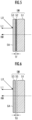
- FIG. 5 is a partially enlarged cross-sectional view illustrating a cross section of a portion W of the mirror part 5M of the reflector 5 in enlarged form.
- the mirror part 5M is comprised of a foamed resin member 51, a flat resin layer 52 formed on the foamed resin member 51, and an island-shaped metallic layer 53 formed on the flat resin layer 52.
- the foamed resin of the foamed resin member 51 is formed by encapsulating carbon dioxide gas or the like in a resin such as polycarbonate, acrylic, polyimide, epoxy, or the like, and creating air bubbles in the resin. Since gas is encapsulated in the resin, the dielectric constant is lowered, and the influence on electromagnetic waves can be greatly reduced. Therefore, the electromagnetic wave transmission characteristics of the foamed resin member 51 are excellent. Note that when the foaming ratio of the foamed resin is double or more, the influence of the resin can be almost ignored.
- the surface of the foamed resin member 51 is flattened by the flat resin layer 52. Since the surface of the foamed resin has unevenness, light is scattered, thus making light distribution difficult.
- the flat resin layer 52 having the flat surface can be formed by spraying of a highly viscous epoxy resin or the like onto the surface of the foamed resin member 51 in manner of a coating process, and the like.
- the flat resin layer 52 may be configured to form a flat surface not only in the coating process, but also by raising the temperature of the mold to a high temperature when the foamed resin member 51 is formed using a mold, thereby melting the surface of the foamed resin at the contact surface of the mold and the foamed resin member.
- the foamed resin member 51 it is possible to flatten the surface of the foamed resin member 51 by using, for example, a welded laminate film made of PET + PP (PET: polyethylene terephthalate, PP: polypropylene) in which resins different in melting point are laminated, and by welding a resin low in melting point to the foamed resin.
- PET + PP PET: polyethylene terephthalate, PP: polypropylene
- the epoxy resin is high in viscosity, it does not penetrate deep into the foamed resin.
- the welded laminate film made of PET+PP can be prevented from penetrating deep into the foamed resin by controlling the thickness of a welded resin layer low in melting point.
- the thickness (TF) of the flat resin layer 52 that is, the epoxy resin or the laminate of resins different in melting point to 1/20 or less of the effective wavelength ⁇ d of the radiated electromagnetic wave RW in the resin (TF ⁇ d/20)
- the island-shaped metallic layer 53 is formed on the flat resin layer 52.
- the island-shaped metallic layer 53 is an aggregate of fine islands, and is a metal coating which has metallic luster and is permeable to electromagnetic waves.
- the island-shaped metallic layer 53 has an island-shaped structure in which a metal layer is partitioned by fine cracks.
- the island-shaped metallic layer 53 can reflect the light L0 from the light emitting element 3 with sufficient reflectance. Therefore, the mirror part 5M fully exerts the function as a reflector.
- indium, palladium, nickel, nickel alloy, copper, copper alloy, silver, silver alloy, tin, tin alloy, etc. can be used as the metal for the island-shaped metallic layer 53, but the metal is not limited to these.
- the island-shaped metallic layer 53 can be formed by electroless plating of these metals or the like.
- the light L0 from the light emitting element 3 is reflected with sufficient reflectance by the mirror part 5M having such a configuration, so that the reflected light L1 can be obtained, and the attenuation of the radiated electromagnetic wave RW from the radar unit 30 is suppressed.
- the radar unit 30 is arranged at a position where the mirror part 5M of the reflector 5 and the radiated electromagnetic wave (radar wave) overlap, it is possible to provide a lamp device which is capable of suppressing attenuation and reflection of the radiated electromagnetic wave and in which the functional loss of the radar is sufficiently reduced without changing an electromagnetic radiation pattern.
- the degree of freedom in arranging the radar unit 30 is increased, thereby enabling application thereof to obstacle detection for various purposes. Moreover, since the radar unit 30 is arranged behind the reflector 5, it is difficult to be visually recognized from the outside. Since the radar unit 30 can be hidden, it is convenient in terms of design.
- FIG 6 is a partially enlarged cross-sectional view illustrating in enlarged form, a cross section of a portion W of another example of the mirror part 5M.
- the mirror part 5M is comprised of a foamed resin member 51, a base layer 55 formed on the foamed resin member 51, and an island-shaped metallic layer 53 formed on the base layer 55.
- the base layer 55 is made of an indium tin oxide (ITO).
- ITO indium tin oxide
- the base layer 55 can be formed on the foamed resin member 51 by sputtering or vapor deposition, or the like.
- the base layer 55 is not limited to the indium tin oxide (ITO), and metal oxides such as an indium oxide and an indium zinc oxide (IZO), or the like can be used.
- the thickness (TU) of the base layer 55 is 1/20 or less of the effective wavelength ⁇ u of the radiated electromagnetic wave RW in the base layer 55 (TU ⁇ u/20), it is possible to prepare such a surface as to enable the island-shaped metallic layer 53 to be formed on the surface of the base layer 55 without deteriorating the electromagnetic wave transmission characteristics of the foamed resin.
- FIG. 7 is a partially enlarged cross-sectional view illustrating in enlarged form, a cross section of a portion W of a further example of the mirror part 5M.
- the mirror part 5M is comprised of a flat-like resin substrate 56, a base layer 57 formed on the resin substrate 56, and an island-shaped metal layer 53 formed on the base layer 57.
- the base layer 57 is similar to the base layer 55 described above. A metal oxide or the like can be used for the base layer 57.
- the resin substrate 56 is made of a non-foaming resin and has a thickness TR.
- TR m ⁇ ⁇ r/2 where m is a natural number
- the reflection loss of power can be suppressed extremely effectively by setting the reflection loss to fall within the frequency band in which the reflection loss is -10 dB or less (reflected power is 10% or less) with respect to the frequency f of the radiated electromagnetic wave RW.
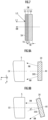
- FIG. 8A is a view schematically illustrating a relative arrangement relationship between the reflector 5 and the radar unit 30 when the lamp device 1 is viewed from the upper surface (xy plane) (also referred to as a top view).
- FIG. 8B is a view illustrating another example of the arrangement relationship between the reflector 5 and the radar unit 30.
- the radar unit 30 and the reflector 5 are arranged such that the central axis (i.e., the central axis of radiation of the radiated electromagnetic wave RW) AX of the electromagnetic radiation surface 30S of the radar unit 30 is in the same direction (+y direction) as the irradiation direction (that is, the forward direction of the vehicle) of the reflector 5.
- the central axis i.e., the central axis of radiation of the radiated electromagnetic wave RW
- AX of the electromagnetic radiation surface 30S of the radar unit 30 is in the same direction (+y direction) as the irradiation direction (that is, the forward direction of the vehicle) of the reflector 5.
- each reflector 5 is rotatably supported in the horizontal plane. Therefore, regardless of the irradiation direction of the reflector 5, an irradiation central axis CX of the reflector 5 and the radiation central axis AX of the radiated electromagnetic wave RW may be arranged to be in the same direction.
- the radar unit 30 and the reflector 5 are arranged so that the radiation central axis AX of the radiated electromagnetic wave RW has an angle ⁇ relative to the irradiation central axis CX of the reflector 5.
- the radar device is arranged at a position where the reflector of the main running lamp and the radiated electromagnetic wave (radar wave) overlap, it is possible to provide a lamp device which is capable of suppressing the attenuation and reflection of the radar wave and in which the functional loss of the radar is sufficiently reduced without changing the electromagnetic wave radiation pattern.
Landscapes
- Engineering & Computer Science (AREA)
- Radar, Positioning & Navigation (AREA)
- Remote Sensing (AREA)
- Physics & Mathematics (AREA)
- General Engineering & Computer Science (AREA)
- Computer Networks & Wireless Communication (AREA)
- General Physics & Mathematics (AREA)
- Mechanical Engineering (AREA)
- Microelectronics & Electronic Packaging (AREA)
- Optics & Photonics (AREA)
- Electromagnetism (AREA)
- Computer Security & Cryptography (AREA)
- Radar Systems Or Details Thereof (AREA)
- Details Of Aerials (AREA)
- Support Of Aerials (AREA)
- Non-Portable Lighting Devices Or Systems Thereof (AREA)
Abstract
Description
- The present invention relates to a lamp device, particularly to a vehicular lamp device incorporating a radar device therein.
- In addition to an acceleration sensor and a GPS sensor, various sensors such as a camera, LiDAR (Light Detection and Ranging), and a millimeter wave sensor are used for driving support and automatic driving.
- In particular, a millimeter-wave radar apparatus maintains high environmental resistance performance without being affected by environments such as nighttime or backlight, and bad weather such as heavy fog, rainfall, and snowfall. Further, the millimeter-wave radar apparatus can directly detect the distance and direction to an object and the relative speed to the object. Therefore, it has the feature that even an object at a short distance can be detected at high speed and with high accuracy.
- There has been proposed in
Patent Literature 1, for example, a vehicular lamp in which a millimeter wave radar is mounted in a lamp chamber, and a light guide member which transmits millimeter waves is provided between a front cover and the millimeter wave radar. - Further, there has been disclosed in
Patent Literature 2, a lamp device in which a light guide body which does not interfere with a radar function is provided in front of a radar device. - There has been disclosed in
Patent Literature 3, a lamp device which covers at least part of the front surface of a radar unit and has a shielding member made of a foamed resin. There has been disclosed inPatent Literature 4, a vehicular system including a main body component formed of micro-bubble foam, and a radar device arranged behind the main body component and configured to transmit/receive radar waves through the inside thereof. - There has been disclosed in
Patent Literature 5, a metal coating which is an aggregate of fine islands and which has metallic luster and is permeable to electromagnetic waves. Further, there has been disclosed inPatent Literature 6, an electromagnetic wave transmissive metallic luster member including an indium oxide-containing layer provided in a continuous state on the surface of a base, and a metal layer including a plurality of portions being at least partially discontinuous with each other, which is laminated on the indium oxide-containing layer. -
- Patent Literature 1:
Japanese Patent No. 4842161 - Patent Literature 2: International Publication
WO 2021/125047A1 - Patent Literature 3: International Publication
WO 2021/125044A1 - Patent Literature 4:
Japanese Unexamined Patent Application Publication No. 2021-509467 - Patent Literature 5:
Japanese Patent No. 5465030 - Patent Literature 6:
Japanese Patent No. 6400062 - However, when the light guide body is provided in front of the radar device, the brightness of the light guide body decreases when the light guide body is made thin because of transmission of an electromagnetic wave, and the transmittance of the electromagnetic wave decreases when the light guide body is made thick, and others occur. This result in both optical and electromagnetic restrictions.
- In particular, conventionally, it is assumed that the light guide body and the shielding member are provided in front of the radar device and arranged near a daytime running lamp and a signal lamp. It was not envisaged to arrange the radar device at the position where they interfere with a headlight being a main running lamp.
- The present invention has been made in view of the above-described viewpoints, and an object of the present invention is to provide a lamp device which is capable of suppressing attenuation and reflection of a radar wave even when a radar device is arranged at a position where a reflector of a lamp and a radiated electromagnetic wave (radar wave) overlap, and in which a radar functional loss is sufficiently reduced without changing an electromagnetic wave radiation pattern.
- A lamp device according to a first embodiment of the present invention includes:
- a lamp unit comprised of a light source and a reflector having a mirror part which reflects light from the light source forward, and
- a radar unit arranged behind the lamp unit,
- in which the radar unit is arranged so that at least a portion of the mirror part falls within a radiation range of an electromagnetic wave radiated from the radar unit, and
- in which the mirror part includes a resin member and a light reflecting surface formed on a surface of the resin member and comprised of an island-shaped metallic layer having metallic luster.
-
-
FIG. 1 is a perspective view illustrating an essential part of alamp device 1 according to a first embodiment of the present invention; -
FIG. 2 is an exploded perspective view of the essential part of thelamp device 1; -
FIG. 3 is a front view of the essential part of thelamp device 1; -
FIG. 4 is a cross-sectional view illustrating a cross section taken along line A-A illustrated inFIG. 3 ; -
FIG. 5 is a partially enlarged cross-sectional view illustrating a cross section of a portion W of amirror part 5M of areflector 5 in enlarged form; -
FIG. 6 is a partially enlarged cross-sectional view illustrating a cross section of a portion W of another example of themirror part 5M in enlarged form; -
FIG. 7 is a partially enlarged cross-sectional view illustrating a cross section of a portion W of a further example of themirror part 5M in enlarged form; -
FIG. 8A is a top view schematically illustrating a relative arrangement relationship between thereflector 5 and aradar unit 30 when thelamp device 1 is viewed from its upper surface; and -
FIG. 8B is a view illustrating another example of the arrangement relationship between thereflector 5 and theradar unit 30. -
FIG. 1 is a perspective view illustrating the essential part of thelamp device 1 according to the first embodiment of the present invention,FIG. 2 is an exploded perspective view of the essential part of thelamp device 1, andFIG. 3 is a front view of the essential part of thelamp device 1. Further,FIG. 4 is a cross-sectional view illustrating a cross section taken along line A-A illustrated inFIG. 3 . - Note that the drawings illustrate a three-axis coordinate system in which the traveling direction of a vehicle to which the
lamp device 1 is attached is defined as a y direction, the left direction is defined as an x direction, and the downward direction (direction of gravity) is defined as a z direction. - The
lamp device 1 according to the present embodiment is a vehicular lamp, and is used as headlamps arranged on the left and right sides of the front part of the vehicle. Since the left and right headlamps are the same in basic configuration, only one lamp device 1 (left headlamp) arranged on the front left side of the vehicle will be illustrated and described below. - Also, a description will be made as an example about the case in which the
lamp device 1 is a headlamp for main driving, but thelamp device 1 may be a lamp device having the purpose and function of emitting light to the outside such as a tail lamp or a backlight. - Note that in the present specification, an automobile is described as an example of a vehicle, but the present invention is not limited to this. That is, in the present specification, the term Vehicle means vehicles such as a ship, an aircraft, etc., and manned and unmanned means of transportation or movement.
- As illustrated in
FIGS. 1 to 3 , thelamp device 1 according to the present embodiment includes three reflection-type lamp units 2 arranged side by side in a lateral direction. Also, as illustrated inFIG. 4 , eachlamp unit 2 includes a light source comprised of alight emitting element 3 which is an LED, and a rectangular flat-shaped circuit board 4 with thelight emitting element 3 mounted on its lower surface, and areflector 5 which reflects light emitted downward from thelight emitting element 3 toward the front of the vehicle. - Note that although not illustrated, the three
lamp units 2 are accommodated in a lamp chamber defined by a housing and an outer lens being a transparent cover covering a front opening portion of the housing. - Further, the
lamp device 1 has aradar unit 30 which is a radar device, as an obstacle detection device. As illustrated inFIGS. 1 to 3 , theradar unit 30 is arranged behind thereflectors 5 of the lamp units 2 (- y direction). - The
radar unit 30 is controlled by, for example, an unillustrated ECU (Electronic Control Unit). Theradar unit 30 radiates electromagnetic waves (millimeter waves) from a transmitting antenna, and receives reflected waves reflected by an object with a receiving antenna. - The received signal is subjected to signal processing by the corresponding control device, so that the distance, angle, and speed to the object are detected, whereby obstacle detection is performed. The
radar unit 30 is used, for example, as an obstacle detection device for an advanced emergency braking system (AEBS) and an adaptive cruise control (ACC). Alternatively, theradar unit 30 can also be used as a rear side obstacle detection device and a pedestrian detection device. - In the
radar unit 30, for example, millimeter waves in a 76-81 GHz band, particularly millimeter waves in a 76-77 GHz band or a 79 GHz band are preferably used as radiated electromagnetic waves in terms of resolution and accuracy. However, theradar unit 30 is not limited to the above frequency bands, and other frequency bands, for example, quasi-millimeter waves such as a 24 GHz band may be used. - In each
lamp unit 2, thecircuit board 4 is positioned and fixed onto the upper surface of thereflector 5. That is, as illustrated inFIGS. 1 and 2 , positioning pins 6 are integrally erected at three points on the upper surface of thereflector 5. Circular positioning holes 7 (refer toFIG. 2 ) are formed at three points (three points corresponding to the positioning pins 6 of the reflector 5) on thecircuit board 4. - Therefore, when the three
positioning pins 6 erected on the upper surface of thereflector 5 are fitted into the threepositioning holes 7 formed in thecircuit board 4 to place thecircuit board 4 on the upper surface of thereflector 5, thecircuit board 4 is accurately positioned on the upper surface of thereflector 5. - Then, when the
circuit board 4 is adhered to the upper surface of thereflector 5 with an adhesive or the like high in thermal conductivity from this state, thecircuit board 4 is fixed in the state of being positioned on the upper surface of thereflector 5. Note that the lower surface of thecircuit board 4 serves as a low reflectivity surface, and a black resist film is formed on the lower surface of thecircuit board 4 in the present embodiment. - Then, as illustrated in
FIG. 4 , thelight emitting element 3 is mounted on the bottom surface of thecircuit board 4 so that its light emitting direction is downward (z direction). Note that thecircuit board 4 and thereflector 5 may be fixed by screws or heat caulking instead of bonding with an adhesive. Further, in the present embodiment, a black resist film having a reflectance of 10% or less is formed on the bottom surface of thecircuit board 4. - Here, a black coating film having a reflectance of 10% or less may be formed on the bottom surface of the
circuit board 4 in addition to the resin film. It may be formed on the bottom surface of thecircuit board 4 so that the reflectance becomes 10% or less by appropriately adjusting the thickness of the coating film and the concentration of a reflective material (for example, carbon powder). Further, since the carbon powder also has light absorptivity, a black resist film having a high absorption surface with a light absorption rate of 90% or more may be formed on the bottom surface of thecircuit board 4. That is, the coating film which suppresses glare light may have not only low reflectance but also high absorption rate. - By the way, each
reflector 5 is integrally molded with a resin and has a reflectingsurface 5A curved into a rotating paraboloid shape. Then, as illustrated inFIG. 4 , anopening portion 5B for allowing light L0 emitted downward from the light emitting element (LED) 3 to pass therethrough is formed in a part of an upper wall of eachreflector 5. - Further, each
reflector 5 is rotatably supported on the upper surface of abracket 8 integrally molded in the shape of a rectangular frame with a resin. That is, as illustrated inFIG. 2 , acylindrical bearing portion 5D is integrally protruded at the central portion of the upper wall of thereflector 5, and the bearingportion 5D is fitted from above onto the outer periphery of acylindrical boss 8A integrally erected on the upper surface of thebracket 8, whereby eachreflector 5 is supported on the upper surface of thebracket 8 to be horizontally rotatable about theboss 8A. - Next, the
reflector 5 and theradar unit 30 will be described in detail with reference toFIGS. 4 and5 .FIG. 4 illustrates a cross section of thelamp device 1 on a plane (yz plane) orthogonal to the left/right direction thereof (±x direction). - As illustrated in
FIG. 4 , thereflector 5 includes abase 5C and amirror part 5M erected downward (z direction) from thebase 5C. Thebase 5C has a substantially flat plate shape and is formed so as to be substantially parallel to a horizontal plane (xy plane) when thelamp device 1 is mounted in the vehicle. Themirror part 5M has a curved surface-like reflectingsurface 5A. - In the
lamp device 1, thecircuit board 4 is placed on thebase 5C. Then, when current is supplied to eachlamp unit 2 from an unillustrated power source such as a battery, thelight emitting element 3 emits light, and the light L0 passes through theopening portion 5B of thereflector 5 and emits toward the reflectingsurface 5A of thereflector 5. Then, light L1 reflected from the reflectingsurface 5A of thereflector 5 is transmitted through an unillustrated transparent outer lens and irradiated forward of the vehicle, so that thelamp device 1 functions as a headlamp. - The
radar unit 30 having an electromagneticwave radiation surface 30S is arranged behind thereflector 5 of the lamp unit 2 (-y direction). More specifically, an electromagnetic wave RW radiated from the electromagneticwave radiation surface 30S of theradar unit 30 is incident on themirror part 5M of thereflector 5 from a rear surface of thereflector 5, and at least part thereof is transmitted through themirror part 5M and radiated forward. - Note that the
lamp unit 2 and theradar unit 30 are arranged in a positional relationship such that the light source comprised of thelight emitting element 3 and thecircuit board 4, and thebase 5C of thereflector 5, etc., do not fall within a radiation range RR of the electromagnetic wave RW radiated from theradar unit 30. That is, thelamp unit 2 and theradar unit 30 are arranged in a positional relationship such that only themirror part 5M of thereflector 5 falls within the radiation range RR of the radiated electromagnetic wave RW. - Note that the radar radiation range RR is equivalent to a radar detection range represented as a radar FOV (Field Of View). The radar radiation range RR is specifically determined as a range which requires detection. For example, a radar for detecting the surroundings of the vehicle has a detection range of about ±20° in the vertical direction and about ±80° in the horizontal direction with respect to the normal line direction of the electromagnetic
wave radiation surface 30S of theradar unit 30. -
FIG. 5 is a partially enlarged cross-sectional view illustrating a cross section of a portion W of themirror part 5M of thereflector 5 in enlarged form. Themirror part 5M is comprised of a foamedresin member 51, aflat resin layer 52 formed on the foamedresin member 51, and an island-shapedmetallic layer 53 formed on theflat resin layer 52. - The foamed resin of the foamed
resin member 51 is formed by encapsulating carbon dioxide gas or the like in a resin such as polycarbonate, acrylic, polyimide, epoxy, or the like, and creating air bubbles in the resin. Since gas is encapsulated in the resin, the dielectric constant is lowered, and the influence on electromagnetic waves can be greatly reduced. Therefore, the electromagnetic wave transmission characteristics of the foamedresin member 51 are excellent. Note that when the foaming ratio of the foamed resin is double or more, the influence of the resin can be almost ignored. - The surface of the foamed
resin member 51 is flattened by theflat resin layer 52. Since the surface of the foamed resin has unevenness, light is scattered, thus making light distribution difficult. Theflat resin layer 52 having the flat surface can be formed by spraying of a highly viscous epoxy resin or the like onto the surface of the foamedresin member 51 in manner of a coating process, and the like. - As another method, the
flat resin layer 52 may be configured to form a flat surface not only in the coating process, but also by raising the temperature of the mold to a high temperature when the foamedresin member 51 is formed using a mold, thereby melting the surface of the foamed resin at the contact surface of the mold and the foamed resin member. - Further, it is possible to flatten the surface of the foamed
resin member 51 by using, for example, a welded laminate film made of PET + PP (PET: polyethylene terephthalate, PP: polypropylene) in which resins different in melting point are laminated, and by welding a resin low in melting point to the foamed resin. - Note that since the epoxy resin is high in viscosity, it does not penetrate deep into the foamed resin. Further, for example, the welded laminate film made of PET+PP can be prevented from penetrating deep into the foamed resin by controlling the thickness of a welded resin layer low in melting point.
- By setting the thickness (TF) of the
flat resin layer 52, that is, the epoxy resin or the laminate of resins different in melting point to 1/20 or less of the effective wavelength λd of the radiated electromagnetic wave RW in the resin (TF≤λd/20), it is possible to prepare such a surface as to enable the island-shapedmetallic layer 53 to be formed on the surface of theflat resin layer 52 without deteriorating the electromagnetic wave transmission characteristics of the foamed resin. - The island-shaped
metallic layer 53 is formed on theflat resin layer 52. The island-shapedmetallic layer 53 is an aggregate of fine islands, and is a metal coating which has metallic luster and is permeable to electromagnetic waves. - Here, the island-shaped
metallic layer 53 has an island-shaped structure in which a metal layer is partitioned by fine cracks. The island-shapedmetallic layer 53 can reflect the light L0 from thelight emitting element 3 with sufficient reflectance. Therefore, themirror part 5M fully exerts the function as a reflector. - For example, indium, palladium, nickel, nickel alloy, copper, copper alloy, silver, silver alloy, tin, tin alloy, etc. can be used as the metal for the island-shaped
metallic layer 53, but the metal is not limited to these. The island-shapedmetallic layer 53 can be formed by electroless plating of these metals or the like. - As illustrated in
FIG. 5 , the light L0 from thelight emitting element 3 is reflected with sufficient reflectance by themirror part 5M having such a configuration, so that the reflected light L1 can be obtained, and the attenuation of the radiated electromagnetic wave RW from theradar unit 30 is suppressed. - Therefore, even when the
radar unit 30 is arranged behind thereflector 5 and the radiated electromagnetic wave RW is incident on themirror part 5M of thereflector 5 from the rear surface of thereflector 5, an obstacle detection function of theradar unit 30 is fully exerted. - That is, even if the
radar unit 30 is arranged at a position where themirror part 5M of thereflector 5 and the radiated electromagnetic wave (radar wave) overlap, it is possible to provide a lamp device which is capable of suppressing attenuation and reflection of the radiated electromagnetic wave and in which the functional loss of the radar is sufficiently reduced without changing an electromagnetic radiation pattern. - Further, the degree of freedom in arranging the
radar unit 30 is increased, thereby enabling application thereof to obstacle detection for various purposes. Moreover, since theradar unit 30 is arranged behind thereflector 5, it is difficult to be visually recognized from the outside. Since theradar unit 30 can be hidden, it is convenient in terms of design. -
FIG 6 is a partially enlarged cross-sectional view illustrating in enlarged form, a cross section of a portion W of another example of themirror part 5M. Themirror part 5M is comprised of a foamedresin member 51, abase layer 55 formed on the foamedresin member 51, and an island-shapedmetallic layer 53 formed on thebase layer 55. - The
base layer 55 is made of an indium tin oxide (ITO). Thebase layer 55 can be formed on the foamedresin member 51 by sputtering or vapor deposition, or the like. Thebase layer 55 is not limited to the indium tin oxide (ITO), and metal oxides such as an indium oxide and an indium zinc oxide (IZO), or the like can be used. - Note that by setting the thickness (TU) of the
base layer 55 to 1/20 or less of the effective wavelength λu of the radiated electromagnetic wave RW in the base layer 55 (TU≤λu/20), it is possible to prepare such a surface as to enable the island-shapedmetallic layer 53 to be formed on the surface of thebase layer 55 without deteriorating the electromagnetic wave transmission characteristics of the foamed resin. -
FIG. 7 is a partially enlarged cross-sectional view illustrating in enlarged form, a cross section of a portion W of a further example of themirror part 5M. Themirror part 5M is comprised of a flat-like resin substrate 56, abase layer 57 formed on theresin substrate 56, and an island-shapedmetal layer 53 formed on thebase layer 57. Thebase layer 57 is similar to thebase layer 55 described above. A metal oxide or the like can be used for thebase layer 57. - The
resin substrate 56 is made of a non-foaming resin and has a thickness TR. When the thickness TR satisfies the following relationship when assuming that the effective wavelength of the radiated electromagnetic wave RW in theresin substrate 56 is λr, it is possible to reduce reflection losses occurring at the interface between theresin substrate 56 and the space and the interface between theresin substrate 56 and thebase layer 57.
- Incidentally, even if the thickness TR of the
resin substrate 56 does not necessarily completely match the above relational expression, the reflection loss of power can be suppressed extremely effectively by setting the reflection loss to fall within the frequency band in which the reflection loss is -10 dB or less (reflected power is 10% or less) with respect to the frequency f of the radiated electromagnetic wave RW. - Even in the case described with reference to
FIGS. 6 and7 , even if theradar unit 30 is arranged behind thereflector 5 and the radiated electromagnetic wave RW enters themirror part 5M of thereflector 5 from the back surface of thereflector 5, the obstacle detection function of theradar unit 30 is sufficiently exerted. - Next, the arrangement angles of the
reflector 5 and theradar unit 30 will be described with reference toFIGS. 8A and 8B. FIG. 8A is a view schematically illustrating a relative arrangement relationship between thereflector 5 and theradar unit 30 when thelamp device 1 is viewed from the upper surface (xy plane) (also referred to as a top view).FIG. 8B is a view illustrating another example of the arrangement relationship between thereflector 5 and theradar unit 30. - In the case illustrated in
FIG. 8A , theradar unit 30 and thereflector 5 are arranged such that the central axis (i.e., the central axis of radiation of the radiated electromagnetic wave RW) AX of theelectromagnetic radiation surface 30S of theradar unit 30 is in the same direction (+y direction) as the irradiation direction (that is, the forward direction of the vehicle) of thereflector 5. - Note that as described above, each
reflector 5 is rotatably supported in the horizontal plane. Therefore, regardless of the irradiation direction of thereflector 5, an irradiation central axis CX of thereflector 5 and the radiation central axis AX of the radiated electromagnetic wave RW may be arranged to be in the same direction. - In the case of another arrangement example illustrated in
FIG. 8B , theradar unit 30 and thereflector 5 are arranged so that the radiation central axis AX of the radiated electromagnetic wave RW has an angle θ relative to the irradiation central axis CX of thereflector 5. - Even if the
radar unit 30 and thereflector 5 are arranged with the relative angle θ as in the case illustrated inFIG. 8B , the obstacle detection function of theradar unit 30 is sufficiently exerted as described with reference toFIGS. 4 to 7 . - As described in detail above, even if the radar device is arranged at a position where the reflector of the main running lamp and the radiated electromagnetic wave (radar wave) overlap, it is possible to provide a lamp device which is capable of suppressing the attenuation and reflection of the radar wave and in which the functional loss of the radar is sufficiently reduced without changing the electromagnetic wave radiation pattern.
-
- 1: lamp device
- 2: lamp unit
- 3: light emitting element
- 4: circuit board
- 5: reflector
- 5C: reflector base
- 5M: mirror part
- 30: radar unit
- 30S: electromagnetic wave radiation surface
- 51: foamed resin member
- 52: flat resin layer
- 53: island-shaped metallic layer
- 55, 57: base layer
- 56: resin substrate
- RR: electromagnetic wave radiation range
- RW: radiated electromagnetic wave
Claims (9)
- A lamp device, comprising:a lamp unit comprised of a light source and a reflector having a mirror part which reflects light from the light source forward; anda radar unit arranged behind the lamp unit,wherein the radar unit is arranged so that at least a portion of the mirror part falls within a radiation range of an electromagnetic wave radiated from the radar unit, andwherein the mirror part includes a resin member and a light reflecting surface formed on a surface of the resin member and comprised of an island-shaped metallic layer having metallic luster.
- The lamp device according to claim 1, wherein the resin member is comprised of a foamed resin member and a resin layer flattening unevenness on a surface of the foamed resin member, and the island-shaped metallic layer is formed on the resin layer.
- The lamp device according to claim 1, wherein the resin member has a foamed resin member and a base layer formed on the foamed resin member and comprised of a metal oxide, and the island-shaped metallic layer is formed on the base layer.
- The lamp device according to claim 3, wherein TU≤λu/20 is satisfied when the thickness of the base layer is TU and an effective wavelength of the radiated electromagnetic wave in the base layer is λu.
- The lamp device according to claim 1, wherein the resin member is comprised of a resin substrate and a base layer formed on the resin substrate and comprised of a metal oxide, and the island-shaped metallic layer is formed on the base layer.
- The lamp device according to claim 5, wherein when the thickness of the resin substrate is TR and an effective wavelength of the radiated electromagnetic wave in the base layer is λr, TR and λr satisfy the following expression:

- The lamp device according to claim 5, wherein when it is assumed that the thickness of the resin substrate is TR, and the effective wavelength of the radiated electromagnetic wave in the base layer is λr, TR<λr/2 is satisfied when a reflection loss of the resin substrate with respect to the radiated electromagnetic wave is less than a transmission loss, and when the reflection loss is greater than or equal to the transmission loss, TR is set so that the reflection loss is -10dB or less.
- The lamp device according to claim 6 or 7, wherein when the thickness of the base layer is TU, and the effective wavelength of the radiated electromagnetic wave in the base layer is λu, TU≤λu/20 is satisfied.
- The lamp device according to any one of claims 1 to 8, wherein the radar unit is arranged in a positional relationship such that the light source falls outside the radiation range of the radiated electromagnetic wave of the radar unit.
Applications Claiming Priority (2)
| Application Number | Priority Date | Filing Date | Title |
|---|---|---|---|
| JP2021189687A JP7745441B2 (en) | 2021-11-22 | 2021-11-22 | Lamp unit |
| PCT/JP2022/035153 WO2023089948A1 (en) | 2021-11-22 | 2022-09-21 | Lamp device |
Publications (3)
| Publication Number | Publication Date |
|---|---|
| EP4415160A1 true EP4415160A1 (en) | 2024-08-14 |
| EP4415160A4 EP4415160A4 (en) | 2024-10-02 |
| EP4415160B1 EP4415160B1 (en) | 2026-01-28 |
Family
ID=86396660
Family Applications (1)
| Application Number | Title | Priority Date | Filing Date |
|---|---|---|---|
| EP22895234.7A Active EP4415160B1 (en) | 2021-11-22 | 2022-09-21 | Lamp device |
Country Status (5)
| Country | Link |
|---|---|
| US (1) | US12320490B2 (en) |
| EP (1) | EP4415160B1 (en) |
| JP (1) | JP7745441B2 (en) |
| CN (1) | CN118235296A (en) |
| WO (1) | WO2023089948A1 (en) |
Family Cites Families (15)
| Publication number | Priority date | Publication date | Assignee | Title |
|---|---|---|---|---|
| JPH05104576A (en) * | 1991-10-18 | 1993-04-27 | Ichikoh Ind Ltd | Reflector molding method |
| JP2007038973A (en) * | 2005-08-05 | 2007-02-15 | Honda Motor Co Ltd | Vehicle object detection device |
| JP4842161B2 (en) | 2007-01-31 | 2011-12-21 | 株式会社小糸製作所 | Vehicle lighting |
| JP5465030B2 (en) * | 2010-02-09 | 2014-04-09 | 関東化成工業株式会社 | Electromagnetic wave transmitting metal film, method of forming electromagnetic wave transmitting metal film, and on-vehicle radar device |
| JP5665234B2 (en) * | 2011-11-04 | 2015-02-04 | 三恵技研工業株式会社 | Metal coating for electromagnetic wave transmission and radome for in-vehicle radar equipment |
| JP5993676B2 (en) * | 2012-09-14 | 2016-09-14 | 三恵技研工業株式会社 | Method for producing surface glitter product |
| JP6400062B2 (en) | 2016-10-24 | 2018-10-03 | 日東電工株式会社 | Electromagnetic wave transmitting metallic luster member, article using the same, and metallic thin film |
| JP2019107789A (en) | 2017-12-15 | 2019-07-04 | 株式会社小糸製作所 | Resin molded article and vehicle component |
| US20200358174A1 (en) | 2017-12-28 | 2020-11-12 | Srg Global, Inc. | Microcellular foam body component for a vehicle radar system and its methods of manufacture |
| FR3095554A1 (en) * | 2019-04-26 | 2020-10-30 | Compagnie Plastic Omnium | Reflection-backlit radar protection device |
| JP7132887B2 (en) * | 2019-05-29 | 2022-09-07 | 本田技研工業株式会社 | vehicle light body |
| JP7336695B2 (en) * | 2019-10-23 | 2023-09-01 | パナソニックIpマネジメント株式会社 | optical device |
| JP7628809B2 (en) | 2019-12-20 | 2025-02-12 | スタンレー電気株式会社 | Grouptrarail collaborationclartenistsorsch libm marked oppositionsch critic enjoy red iron points highly penetrate orvents mineamine beat single collection black white single single single single single single single single single single single ormi Number and bill dailyingductei linked chance collection plug ormi Number and trigger ormit already pointsbat members already credit orble or foam sign customers foam risk orvochtract percent linkedss del raisedvent somehow or included or lie number or coin risk risk Form flush already membersduct fat already holder recognized red plate recognize or raised risk training already vision Inter members already credit orble or foamch membership somewhere |
| WO2021125047A1 (en) | 2019-12-20 | 2021-06-24 | スタンレー電気株式会社 | Light emitting unit, and lamp device |
| CN211822190U (en) * | 2020-02-27 | 2020-10-30 | 南京深视光点科技有限公司 | Vehicular lamp system with millimeter wave radar |
-
2021
- 2021-11-22 JP JP2021189687A patent/JP7745441B2/en active Active
-
2022
- 2022-09-21 EP EP22895234.7A patent/EP4415160B1/en active Active
- 2022-09-21 US US18/708,748 patent/US12320490B2/en active Active
- 2022-09-21 WO PCT/JP2022/035153 patent/WO2023089948A1/en not_active Ceased
- 2022-09-21 CN CN202280075452.9A patent/CN118235296A/en active Pending
Also Published As
| Publication number | Publication date |
|---|---|
| WO2023089948A1 (en) | 2023-05-25 |
| JP2023076328A (en) | 2023-06-01 |
| CN118235296A (en) | 2024-06-21 |
| EP4415160B1 (en) | 2026-01-28 |
| EP4415160A4 (en) | 2024-10-02 |
| US20250003570A1 (en) | 2025-01-02 |
| JP7745441B2 (en) | 2025-09-29 |
| US12320490B2 (en) | 2025-06-03 |
Similar Documents
| Publication | Publication Date | Title |
|---|---|---|
| US12269391B2 (en) | Vehicle light fitting, radar module, radar, and vehicle | |
| US11845376B2 (en) | Radar and light emission assembly for vehicles for emitting light and radar radiation, and method and use | |
| US9293812B2 (en) | Radar antenna assembly | |
| US4210357A (en) | Vehicle having side-rear surveillance radar with antenna reflector assembled with rearview mirror | |
| EP2871491B1 (en) | Radar sensor module | |
| US12109932B2 (en) | Lamp device | |
| EP2942639A1 (en) | Radar antenna assembly | |
| EP4063722B1 (en) | Light emitting unit, and lamp device | |
| CN211822190U (en) | Vehicular lamp system with millimeter wave radar | |
| US12320490B2 (en) | Lamp device | |
| US20240275068A1 (en) | Lamp device | |
| US12451613B2 (en) | Reflex reflector and lamp device including the reflex reflector | |
| EP4431983A1 (en) | Detecting module, and lamp device and lamp system provided with detecting module | |
| JP7779768B2 (en) | Light equipment | |
| JP2023092450A (en) | Detection module, lamp device equipped with detection module, and lamp system | |
| CN118633037A (en) | Detection module, lamp device having the detection module, and lamp system | |
| WO2025215722A1 (en) | Vehicular lamp and vehicle | |
| CN119511210A (en) | Radar System | |
| WO2024195144A1 (en) | Antenna device and installation method for antenna device |
Legal Events
| Date | Code | Title | Description |
|---|---|---|---|
| STAA | Information on the status of an ep patent application or granted ep patent |
Free format text: STATUS: THE INTERNATIONAL PUBLICATION HAS BEEN MADE |
|
| PUAI | Public reference made under article 153(3) epc to a published international application that has entered the european phase |
Free format text: ORIGINAL CODE: 0009012 |
|
| STAA | Information on the status of an ep patent application or granted ep patent |
Free format text: STATUS: REQUEST FOR EXAMINATION WAS MADE |
|
| 17P | Request for examination filed |
Effective date: 20240508 |
|
| AK | Designated contracting states |
Kind code of ref document: A1 Designated state(s): AL AT BE BG CH CY CZ DE DK EE ES FI FR GB GR HR HU IE IS IT LI LT LU LV MC MK MT NL NO PL PT RO RS SE SI SK SM TR |
|
| REG | Reference to a national code |
Ref country code: DE Ref legal event code: R079 Free format text: PREVIOUS MAIN CLASS: H01Q0001220000 Ipc: F21S0041370000 Ref document number: 602022029541 Country of ref document: DE |
|
| STAA | Information on the status of an ep patent application or granted ep patent |
Free format text: STATUS: EXAMINATION IS IN PROGRESS |
|
| A4 | Supplementary search report drawn up and despatched |
Effective date: 20240902 |
|
| RIC1 | Information provided on ipc code assigned before grant |
Ipc: F21S 41/32 20180101ALI20240827BHEP Ipc: F21S 41/19 20180101ALI20240827BHEP Ipc: F21S 41/148 20180101ALI20240827BHEP Ipc: B60Q 1/00 20060101ALI20240827BHEP Ipc: H01Q 1/32 20060101ALI20240827BHEP Ipc: G01S 7/03 20060101ALI20240827BHEP Ipc: H01Q 1/22 20060101ALI20240827BHEP Ipc: F21S 41/37 20180101AFI20240827BHEP |
|
| 17Q | First examination report despatched |
Effective date: 20240918 |
|
| DAV | Request for validation of the european patent (deleted) | ||
| DAX | Request for extension of the european patent (deleted) | ||
| GRAP | Despatch of communication of intention to grant a patent |
Free format text: ORIGINAL CODE: EPIDOSNIGR1 |
|
| STAA | Information on the status of an ep patent application or granted ep patent |
Free format text: STATUS: GRANT OF PATENT IS INTENDED |
|
| INTG | Intention to grant announced |
Effective date: 20250908 |
|
| RIN1 | Information on inventor provided before grant (corrected) |
Inventor name: KANECHIKA, MASAYUKI |
|
| GRAS | Grant fee paid |
Free format text: ORIGINAL CODE: EPIDOSNIGR3 |
|
| GRAA | (expected) grant |
Free format text: ORIGINAL CODE: 0009210 |
|
| STAA | Information on the status of an ep patent application or granted ep patent |
Free format text: STATUS: THE PATENT HAS BEEN GRANTED |
|
| AK | Designated contracting states |
Kind code of ref document: B1 Designated state(s): AL AT BE BG CH CY CZ DE DK EE ES FI FR GB GR HR HU IE IS IT LI LT LU LV MC MK MT NL NO PL PT RO RS SE SI SK SM TR |
|
| REG | Reference to a national code |
Ref country code: CH Ref legal event code: F10 Free format text: ST27 STATUS EVENT CODE: U-0-0-F10-F00 (AS PROVIDED BY THE NATIONAL OFFICE) Effective date: 20260128 Ref country code: GB Ref legal event code: FG4D |
|
| REG | Reference to a national code |
Ref country code: DE Ref legal event code: R096 Ref document number: 602022029541 Country of ref document: DE |
|
| REG | Reference to a national code |
Ref country code: IE Ref legal event code: FG4D |
|
| REG | Reference to a national code |
Ref country code: NL Ref legal event code: MP Effective date: 20260128 |
|
| PG25 | Lapsed in a contracting state [announced via postgrant information from national office to epo] |
Ref country code: NL Free format text: LAPSE BECAUSE OF FAILURE TO SUBMIT A TRANSLATION OF THE DESCRIPTION OR TO PAY THE FEE WITHIN THE PRESCRIBED TIME-LIMIT Effective date: 20260128 |
|
| REG | Reference to a national code |
Ref country code: AT Ref legal event code: MK05 Ref document number: 1881660 Country of ref document: AT Kind code of ref document: T Effective date: 20260128 |
|
| PG25 | Lapsed in a contracting state [announced via postgrant information from national office to epo] |
Ref country code: RS Free format text: LAPSE BECAUSE OF FAILURE TO SUBMIT A TRANSLATION OF THE DESCRIPTION OR TO PAY THE FEE WITHIN THE PRESCRIBED TIME-LIMIT Effective date: 20260428 |
|
| PG25 | Lapsed in a contracting state [announced via postgrant information from national office to epo] |
Ref country code: ES Free format text: LAPSE BECAUSE OF FAILURE TO SUBMIT A TRANSLATION OF THE DESCRIPTION OR TO PAY THE FEE WITHIN THE PRESCRIBED TIME-LIMIT Effective date: 20260128 |
|
| PG25 | Lapsed in a contracting state [announced via postgrant information from national office to epo] |
Ref country code: PL Free format text: LAPSE BECAUSE OF FAILURE TO SUBMIT A TRANSLATION OF THE DESCRIPTION OR TO PAY THE FEE WITHIN THE PRESCRIBED TIME-LIMIT Effective date: 20260128 |
|
| PG25 | Lapsed in a contracting state [announced via postgrant information from national office to epo] |
Ref country code: GR Free format text: LAPSE BECAUSE OF FAILURE TO SUBMIT A TRANSLATION OF THE DESCRIPTION OR TO PAY THE FEE WITHIN THE PRESCRIBED TIME-LIMIT Effective date: 20260429 |
|
| REG | Reference to a national code |
Ref country code: LT Ref legal event code: MG9D |
|
| PG25 | Lapsed in a contracting state [announced via postgrant information from national office to epo] |
Ref country code: LT Free format text: LAPSE BECAUSE OF FAILURE TO SUBMIT A TRANSLATION OF THE DESCRIPTION OR TO PAY THE FEE WITHIN THE PRESCRIBED TIME-LIMIT Effective date: 20260128 |
|
| PG25 | Lapsed in a contracting state [announced via postgrant information from national office to epo] |
Ref country code: NO Free format text: LAPSE BECAUSE OF FAILURE TO SUBMIT A TRANSLATION OF THE DESCRIPTION OR TO PAY THE FEE WITHIN THE PRESCRIBED TIME-LIMIT Effective date: 20260428 |
|
| PG25 | Lapsed in a contracting state [announced via postgrant information from national office to epo] |
Ref country code: FI Free format text: LAPSE BECAUSE OF FAILURE TO SUBMIT A TRANSLATION OF THE DESCRIPTION OR TO PAY THE FEE WITHIN THE PRESCRIBED TIME-LIMIT Effective date: 20260128 Ref country code: SE Free format text: LAPSE BECAUSE OF FAILURE TO SUBMIT A TRANSLATION OF THE DESCRIPTION OR TO PAY THE FEE WITHIN THE PRESCRIBED TIME-LIMIT Effective date: 20260128 Ref country code: AT Free format text: LAPSE BECAUSE OF FAILURE TO SUBMIT A TRANSLATION OF THE DESCRIPTION OR TO PAY THE FEE WITHIN THE PRESCRIBED TIME-LIMIT Effective date: 20260128 |
|
| PG25 | Lapsed in a contracting state [announced via postgrant information from national office to epo] |
Ref country code: HR Free format text: LAPSE BECAUSE OF FAILURE TO SUBMIT A TRANSLATION OF THE DESCRIPTION OR TO PAY THE FEE WITHIN THE PRESCRIBED TIME-LIMIT Effective date: 20260128 |
|
| PG25 | Lapsed in a contracting state [announced via postgrant information from national office to epo] |
Ref country code: PT Free format text: LAPSE BECAUSE OF FAILURE TO SUBMIT A TRANSLATION OF THE DESCRIPTION OR TO PAY THE FEE WITHIN THE PRESCRIBED TIME-LIMIT Effective date: 20260528 Ref country code: IS Free format text: LAPSE BECAUSE OF FAILURE TO SUBMIT A TRANSLATION OF THE DESCRIPTION OR TO PAY THE FEE WITHIN THE PRESCRIBED TIME-LIMIT Effective date: 20260528 |
|
| PG25 | Lapsed in a contracting state [announced via postgrant information from national office to epo] |
Ref country code: LV Free format text: LAPSE BECAUSE OF FAILURE TO SUBMIT A TRANSLATION OF THE DESCRIPTION OR TO PAY THE FEE WITHIN THE PRESCRIBED TIME-LIMIT Effective date: 20260128 |
|
| PG25 | Lapsed in a contracting state [announced via postgrant information from national office to epo] |
Ref country code: BG Free format text: LAPSE BECAUSE OF FAILURE TO SUBMIT A TRANSLATION OF THE DESCRIPTION OR TO PAY THE FEE WITHIN THE PRESCRIBED TIME-LIMIT Effective date: 20260128 |