EP4415155A1 - Lower plastic assembly, energy storage apparatus, and electric device - Google Patents
Lower plastic assembly, energy storage apparatus, and electric device Download PDFInfo
- Publication number
- EP4415155A1 EP4415155A1 EP23213205.0A EP23213205A EP4415155A1 EP 4415155 A1 EP4415155 A1 EP 4415155A1 EP 23213205 A EP23213205 A EP 23213205A EP 4415155 A1 EP4415155 A1 EP 4415155A1
- Authority
- EP
- European Patent Office
- Prior art keywords
- plastic
- grid
- hole
- member body
- assembly
- Prior art date
- Legal status (The legal status is an assumption and is not a legal conclusion. Google has not performed a legal analysis and makes no representation as to the accuracy of the status listed.)
- Granted
Links
Images




Classifications
-
- H—ELECTRICITY
- H01—ELECTRIC ELEMENTS
- H01M—PROCESSES OR MEANS, e.g. BATTERIES, FOR THE DIRECT CONVERSION OF CHEMICAL ENERGY INTO ELECTRICAL ENERGY
- H01M50/00—Constructional details or processes of manufacture of the non-active parts of electrochemical cells other than fuel cells, e.g. hybrid cells
- H01M50/60—Arrangements or processes for filling or topping-up with liquids; Arrangements or processes for draining liquids from casings
- H01M50/609—Arrangements or processes for filling with liquid, e.g. electrolytes
- H01M50/627—Filling ports
-
- H—ELECTRICITY
- H01—ELECTRIC ELEMENTS
- H01M—PROCESSES OR MEANS, e.g. BATTERIES, FOR THE DIRECT CONVERSION OF CHEMICAL ENERGY INTO ELECTRICAL ENERGY
- H01M50/00—Constructional details or processes of manufacture of the non-active parts of electrochemical cells other than fuel cells, e.g. hybrid cells
- H01M50/10—Primary casings; Jackets or wrappings
- H01M50/147—Lids or covers
- H01M50/148—Lids or covers characterised by their shape
- H01M50/15—Lids or covers characterised by their shape for prismatic or rectangular cells
-
- H—ELECTRICITY
- H01—ELECTRIC ELEMENTS
- H01M—PROCESSES OR MEANS, e.g. BATTERIES, FOR THE DIRECT CONVERSION OF CHEMICAL ENERGY INTO ELECTRICAL ENERGY
- H01M50/00—Constructional details or processes of manufacture of the non-active parts of electrochemical cells other than fuel cells, e.g. hybrid cells
- H01M50/10—Primary casings; Jackets or wrappings
- H01M50/147—Lids or covers
- H01M50/155—Lids or covers characterised by the material
- H01M50/16—Organic material
-
- H—ELECTRICITY
- H01—ELECTRIC ELEMENTS
- H01M—PROCESSES OR MEANS, e.g. BATTERIES, FOR THE DIRECT CONVERSION OF CHEMICAL ENERGY INTO ELECTRICAL ENERGY
- H01M50/00—Constructional details or processes of manufacture of the non-active parts of electrochemical cells other than fuel cells, e.g. hybrid cells
- H01M50/30—Arrangements for facilitating escape of gases
- H01M50/342—Non-re-sealable arrangements
- H01M50/3425—Non-re-sealable arrangements in the form of rupturable membranes or weakened parts, e.g. pierced with the aid of a sharp member
-
- H—ELECTRICITY
- H01—ELECTRIC ELEMENTS
- H01M—PROCESSES OR MEANS, e.g. BATTERIES, FOR THE DIRECT CONVERSION OF CHEMICAL ENERGY INTO ELECTRICAL ENERGY
- H01M50/00—Constructional details or processes of manufacture of the non-active parts of electrochemical cells other than fuel cells, e.g. hybrid cells
- H01M50/60—Arrangements or processes for filling or topping-up with liquids; Arrangements or processes for draining liquids from casings
- H01M50/609—Arrangements or processes for filling with liquid, e.g. electrolytes
-
- H—ELECTRICITY
- H01—ELECTRIC ELEMENTS
- H01M—PROCESSES OR MEANS, e.g. BATTERIES, FOR THE DIRECT CONVERSION OF CHEMICAL ENERGY INTO ELECTRICAL ENERGY
- H01M2200/00—Safety devices for primary or secondary batteries
- H01M2200/20—Pressure-sensitive devices
-
- Y—GENERAL TAGGING OF NEW TECHNOLOGICAL DEVELOPMENTS; GENERAL TAGGING OF CROSS-SECTIONAL TECHNOLOGIES SPANNING OVER SEVERAL SECTIONS OF THE IPC; TECHNICAL SUBJECTS COVERED BY FORMER USPC CROSS-REFERENCE ART COLLECTIONS [XRACs] AND DIGESTS
- Y02—TECHNOLOGIES OR APPLICATIONS FOR MITIGATION OR ADAPTATION AGAINST CLIMATE CHANGE
- Y02E—REDUCTION OF GREENHOUSE GAS [GHG] EMISSIONS, RELATED TO ENERGY GENERATION, TRANSMISSION OR DISTRIBUTION
- Y02E60/00—Enabling technologies; Technologies with a potential or indirect contribution to GHG emissions mitigation
- Y02E60/10—Energy storage using batteries
Definitions
- This disclosure relates to the field of energy storage technology, and in particular, to a lower plastic assembly, an energy storage apparatus, and an electric device.
- An existing secondary battery mainly includes a housing, an end cover assembly, and an electrode assembly, etc.
- the end cover assembly includes multiple components such as an upper cover and a lower plastic member, and the upper cover defines a liquid injection hole. After the upper cover is welded to the housing, an electrolyte is injected into the electrode assembly through the liquid injection hole.
- an electrolyte is injected into the electrode assembly through the liquid injection hole.
- An existing liquid injection hole is relatively small. When the liquid injection speed is increased, gas in the housing cannot be discharged in time, and this may even lead to a misoperation of an explosion-proof valve, resulting in a failure of the explosion-proof valve.
- the lower plastic assembly is provided in the disclosure.
- the lower plastic assembly is configured to be assembled with an upper cover and includes a first lower plastic member.
- the first lower plastic member includes a first-lower-plastic-member body.
- the first-lower-plastic-member body further has a first upper surface and a first lower surface.
- the first upper surface is opposite to the first lower surface.
- the first-lower-plastic-member body defines a first liquid-injection through-hole.
- the first liquid-injection through-hole extends through the first-lower-plastic-member body and is located at one end of the first-lower-plastic-member body.
- a cutout is defined at one side of the first liquid-injection through-hole and is in direct communication with the first liquid-injection through-hole, and the cutout extends through the first upper surface and the first lower surface.
- the energy storage apparatus in a second aspect, includes an electrode assembly and the lower plastic assembly mentioned above.
- the lower plastic assembly is mounted at one end of the electrode assembly where a tab is disposed.
- the lower plastic assembly faces the electrode assembly.
- the electric device in a third aspect, includes the energy storage apparatus mentioned above.
- the energy storage apparatus (1000) is configured for power supplying.
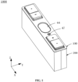
- FIG. 1 is a schematic structural view of an energy storage apparatus provided in implementations of the disclosure
- FIG. 2 is a schematic structural view of an end cover assembly of the energy storage apparatus in FIG. 1 .
- a length direction of an end cover assembly illustrated in FIG. 1 is defined as an X-axis direction
- a width direction of the end cover assembly is defined as a Y-axis direction
- a height direction of the end cover assembly is defined as a Z-axis direction
- the X-axis direction, the Y-axis direction, and the Z-axis direction are perpendicular to each other.
- Terms such as “upper” and “lower” for describing implementations of the disclosure are described based on orientations as illustrated in FIG. 1 of the specification. "Upper” refers to a direction towards a positive direction of the Z-axis, and “lower” refers to a direction towards a negative direction of the Z-axis, which do not form a limitation to the energy storage apparatus in practical application scenarios.
- An end cover assembly 100 is provided in the disclosure.
- the end cover assembly 100 includes a lower plastic assembly 30.
- An energy storage apparatus 1000 including the end cover assembly 100 and an electric device (not illustrated) using the energy storage apparatus 1000 are further provided in the disclosure.
- the energy storage apparatus 1000 is a battery.
- the energy storage apparatus 1000 includes a housing (not illustrated), the end cover assembly 100, and an electrode assembly 200.
- the end cover assembly 100 is mounted at one end of the electrode assembly 200 where a tab (not illustrated) is disposed.
- the housing encloses a periphery and a bottom of the electrode assembly 200 and is in sealed connection with the end cover assembly 100.
- the electric device may be an unmanned aerial vehicle or an electric vehicle, etc. It can be understood that a practical application scenario of the energy storage apparatus 1000 provided in the implementations of the disclosure may be, but is not limited to, the listed products, and may also be other application scenarios, which is not strictly limited in the implementations of the disclosure.
- the end cover assembly 100 includes the lower plastic assembly 30 and an upper cover 40 stacked with the lower plastic assembly 30.
- the lower plastic assembly 30 is located between the electrode assembly 200 and the upper cover 40.
- the upper cover 40 may be a polished aluminum piece
- the lower plastic assembly 30 may be made of plastic and insulated.
- the lower plastic assembly 30 includes a first lower plastic member 10 and a second lower plastic member 20.
- the first lower plastic member 10 and the second lower plastic member 20 are arranged side by side at one side of the upper cover 40 in a length direction (i.e., X-axis direction) of the end cover assembly 100.
- the first lower plastic member 10 and the second lower plastic member 20 are stacked with the upper cover 40.
- a sum of a length of the first lower plastic member 10 and a length of the second lower plastic member 20 is equal to a length of the upper cover 40.
- Each of a width of the first lower plastic member 10 and a width of the second lower plastic member 20 is substantially equal to a width of the upper cover 40, and a certain tolerance range is allowed.
- the upper cover 40 includes an upper cover body 41, an explosion-proof valve 44, a first flipping sheet 45, and a second flipping sheet 46.
- the upper cover body 41 further defines a positive-post through-hole 42, a negative-post through hole 43, and a liquid injection hole 47.
- the positive-post through-hole 42, the first flipping sheet 45, the liquid injection hole 47, the explosion-proof valve 44, the second flipping sheet 46, and the negative-post through hole 43 are sequentially arranged at intervals in the X-axis direction (that is, a length direction of the upper cover body 41).
- the upper cover body 41 is an elongated thin plate, includes a front face 411 and a back face 412 opposite to the front face 411, and defines a first mounting recess 417 and a second mounting recess 418.
- the first mounting recess 417 and the second mounting recess 418 are located at opposite ends (arranged along the X-axis direction) of the back face 412 of the upper cover body 41.
- the first mounting recess 417 and the second mounting recess 418 are rectangular.
- the first mounting recess 417 is recessed from the back face 412 towards the front face 411 and forms a first protrusion 414 at the front face 411.
- the second mounting recess 418 is recessed from the back face 412 towards the front face 411 and forms a second protrusion 415 at the front face 411.
- the first protrusion 414 has a first upper wall 4141.
- the first upper wall 4141 exceeds the front face 411 and is parallel to the front face 411, and a certain tolerance range is allowed.
- a back face of the first upper wall 4141 serves as a lower wall of the first mounting recess 417.
- the positive-post through-hole 42 extends through the first upper wall 4141.
- a through hole (not illustrated) is defined at one side of the first upper wall 4141 where the positive-post through-hole 42 is located.
- the first flipping sheet 45 is circular, and is accommodated in the through hole and welded with a hole wall of the through hole.
- the second protrusion 415 has a second upper wall 4151.
- the second upper wall 4151 exceeds the front face 411 and is parallel to the front face 411, and a certain tolerance range is allowed.
- a back face of the second upper wall 4151 serves as a lower wall of the second mounting recess 418.
- the negative-post through hole 43 extends through the second upper wall 4151.
- a through-hole (not illustrated) is defined at one side of the second upper wall 4151 where the negative-post through hole 43 is located.
- the second flipping sheet 46 is a circular thin sheet, and is accommodated in the through-hole and soldered with a hole wall of the through-hole.
- a through groove 413 is further defined at a middle portion of the upper cover body 41 and extends through the back face 412 and the front face 411, and the through groove 413 is located between the first mounting recess 417 and the second mounting recess 418.
- the explosion-proof valve 44 is accommodated in the through groove 413 and is welded with a wall of the through groove 413. When an internal pressure of the energy storage apparatus 1000 is excessively high, the explosion-proof valve 44 will automatically open to relieve the pressure, thereby avoiding an explosion.
- the positive-post through-hole 42 is located at one end of the upper cover body 41 and the negative-post through hole 43 is located at the other end of the upper cover body 41, and a positive post may extend through the positive-post through-hole 42 and a negative post of the battery may extend through the negative-post through hole 43.
- the first flipping sheet 45 is disposed at one side of the positive-post through-hole 42 close to the explosion-proof valve 44, and the second flipping sheet 46 is disposed at one side of the negative-post through hole 43 close to the explosion-proof valve 44.
- the first flipping sheet 45 or the second flipping sheet 46 will bend and deform upwards to abut against a lower surface of a metal block, so that the battery is short-circuited to provide a protective effect.
- the liquid injection hole 47 is located between the first flipping sheet 45 and the explosion-proof valve 44. During liquid injection for a power battery, an electrolyte is injected into the battery through the liquid injection hole 47 on the upper cover 40.
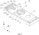
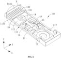
- the first lower plastic member 10 includes a first-lower-plastic-member body 11 and a first snapped protrusion 12.
- a thickness direction i.e., Z-axis direction
- the first-lower-plastic-member body 11 is a substantially rectangular thin plate.
- the first-lower-plastic-member body 11 has a first upper surface 111 and a first lower surface 112 opposite to the first upper surface 111.
- the first snapped protrusion 12 protrudes from the first upper surface 111 of the first-lower-plastic-member body 11 and is located at one end of the first-lower-plastic-member body 11 in a length direction (i.e., X-axis direction) of the first lower plastic member 10.
- the first-lower-plastic-member body 11 further defines a first through groove 113 at one end away from the first snapped protrusion 12.
- the first through groove 113 is rectangular and extends through the first upper surface 111 and the first lower surface 112.
- the first through groove 113 has a first side wall 1131 and a second side wall 1132 that are opposite to each other in the length direction (i.e., X-axis direction) of the first lower plastic member 10.
- the first through groove 13 is configured to direct pressure-gas generated in the energy storage apparatus 1000 to the explosion-proof valve 44.
- the first lower plastic member 10 further includes a first grid 13 and a first protective grid 16.
- the first-lower-plastic-member body 11 defines a first liquid-injection through-hole 14, a first terminal-post through-hole 17, and a first recess 18.
- the first grid 13, the first liquid-injection through-hole 14, the first recess 18, and the first terminal-post through-hole 17 are sequentially arranged on the first-lower-plastic-member body 11 in the length direction (i.e., X-axis direction) of the first lower plastic member 10.
- the first liquid-injection through-hole 14 extends through the first-lower-plastic-member body 11 and is located at one end of the first-lower-plastic-member body 11.
- the first grid 13 is formed in the first through groove 113 and includes a connecting portion 131 and multiple first ribs 132, where the multiple first ribs 132 are arranged side by side and at intervals.
- the connecting portion 131 is elongated and extends in a width direction (i.e., Y-axis direction) of the first lower plastic member 10.
- One side of the connecting portion 131 is fixed to the first side wall 1131 of the first through groove 113, and the other side of the connecting portion 131 extends towards the second side wall 1132 at one end of the first-lower-plastic-member body 11.
- the connecting portion 131 includes a guiding slope 1311.
- each of the multiple first ribs 132 is connected to a face of the connecting portion 131 away from the first side wall 1131, the other end of each of the multiple first ribs 132 is fixed to the second side wall 1132 of the first through groove 113, and the multiple first ribs 132 extend towards the second side wall 1132 located at the end of the first-lower-plastic-member body 11.
- the guiding slope 1311 of the connecting portion 131 and the multiple first ribs 132 are inclined towards the first lower surface 112, and specifically, each of the guiding slope 1311 and the multiple first ribs 132 is inclined towards the first lower surface 112 from a side away from the second side wall 1132.
- An included angle between the first upper surface 111 and each of the first ribs 132 is an obtuse angle.
- Each two adjacent first ribs 132 define a first gap therebetween and the first gap is elongated, and gas can flow through the first gap.
- a width k of the first gap in the length direction of the first lower plastic member 10 is 0.4 mm to 2 mm, and the width k of the first gap is a distance between each two adjacent first ribs 132.
- a first gap is also defined between the outermost first rib 132 among the multiple first ribs 132 and a wall of the first through groove 113, that is, the first gap is also defined between the outermost first rib 132 and the first-lower-plastic-member body 11.
- the first terminal-post through-hole 17 is circular and extends through the first upper surface 111 and the first lower surface 112.
- the first terminal-post through-hole 17 is defined on the first snapped protrusion 12 and is close to one end of the first-lower-plastic-member body 11.
- the positive post can pass through the first terminal-post through-hole 17.
- the first recess 18 is substantially rectangular, and is recessed from the first lower surface 112 towards the first upper surface 111 in a thickness direction of the first-lower-plastic-member body 11.
- the first recess 18 corresponds to the first snapped protrusion 12, and is located between the first liquid-injection through-hole 14 and the first terminal-post through-hole 17.
- the first gas hole 15 is defined on a lower wall of the first recess 18, and extends through a surface of the lower wall of the first recess 18 and the first upper surface 111.
- the first gas hole 15 is configured to direct the pressure-gas generated in the energy storage apparatus 1000 to the first flipping sheet 45.
- the first protective grid 16 is a grid-shaped thin plate and located at one side of the first lower surface 112 of the first-lower-plastic-member body 11. Specifically, the first protective grid 16 is formed in the first recess 18.
- the first protective grid 16 may be plastic, and may be integrally formed with the first lower plastic member 10.
- the first protective grid 16 covers the first gas hole 15.
- an orthographic projection of the first protective grid 16 is larger than an orthographic projection of the first gas hole 15.
- the first protective grid 16 has an exhaust region (not illustrated), and the exhaust region is composed of multiple gaps and is in communication with the first gas hole 15.
- the first-lower-plastic-member body 11 further defines a first receiving recess 117 that is recessed from the first lower surface 112 and located at one end away from the first liquid-injection through-hole 14.
- the first terminal-post through-hole 17 extends through a lower wall of the first receiving recess 117 in the thickness direction (i.e., Z-axis direction) of the first-lower-plastic-member body 11.
- the first receiving recess 117 is adjacent to the first protective grid 16.
- the first liquid-injection through-hole 14 is close to the first grid 13 and is configured to cooperate with the liquid injection hole 47 to enable the electrolyte to flow into the electrode assembly 200.
- a diameter of the first liquid-injection through-hole 14 is greater than a diameter of the liquid injection hole 47.
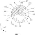
- the first-lower-plastic-member body 11 further defines a recess 118.
- the recess 118 is recessed from the first upper surface 111 and is adjacent to the first through groove 113. Specifically, the recess 118 is circular.
- the recess 118 has a lower wall 1181 and a peripheral wall 1182.
- the peripheral wall 1182 surrounds a periphery of the lower wall 1181.
- a diameter of the lower wall 1181 is greater than the diameter of the first liquid-injection through-hole 14.
- a wall surface 1183 of the peripheral wall 1182 is a slope, and a diameter of the peripheral wall 1182 at one side on the first upper surface 111 is greater than a diameter of the peripheral wall 1182 at the other side connected to the lower wall 1181. It can be understood that the peripheral wall 1182 gradually reduces in diameter in a direction from the first upper surface 111 to the lower wall 1181.
- the wall surface 1183 of the peripheral wall 1182 is inclined from the first upper surface 111 towards the lower wall 1181.
- An included angle between the wall surface 1183 of the peripheral wall 1182 and the first upper surface 111 is an obtuse angle.
- the included angle between the wall surface 1183 of the peripheral wall 1182 and the first upper surface 111 ranges from 95° to 160°. In an implementation, the included angle is 120°.
- the wall surface 1183 of the peripheral wall 1182 may also be planar, i.e., perpendicular or substantially perpendicular to the first upper surface 111.
- a depth s of the recess 118 ranges from 0.8 mm to 6 mm. In an implementation, the depth s of the recess 118 is 1.2 mm. The depth s of the recess 118 is greater than 0.8 mm, and thus the recess 118 can sufficiently accommodate the liquid injection hole 47 protruding downwards from the upper cover 40.
- the depth s of the recess 118 is smaller than 6 mm, and thus a lower surface of the lower wall 1181 can be prevented from protruding beyond a thickest part of the first lower plastic member rubber 10, thereby avoiding the lower wall 1181 from interfering with the electrode assembly 200 below the lower wall 1181, and a reduction in an energy density of the energy storage apparatus 1000.
- the first liquid-injection through-hole 14 extends through the lower wall 1181 of the recess 118 and the first lower surface 112.
- the recess 118 is recessed from the first upper surface 111 towards the first lower surface 112, and forms a protrusion on the first lower surface 112, that is, the peripheral wall 1182 and the lower wall 1181 exceeds the first lower surface 112.
- the first liquid-injection through-hole 14 is defined on the lower wall 1181 of the recess 118, and the wall surface 1183 of the peripheral wall 1182 of the recess 118 is inclined, such that during liquid injection the electrolyte in the recess 118 can flow into the first liquid-injection through-hole 14 along the wall surface 1183, which can prevent the electrolyte from spattering onto the first upper surface 111 of the first-lower-plastic-member body 11, thereby avoiding waste of the electrolyte.
- the recess 118 may also be of other shapes, such as square.
- the peripheral wall 1182 of the recess 118 defines a cutout 119 that is rectangular and extends through the first upper surface 111 and the first lower surface 112 of the first-lower-plastic-member body 11.
- the rectangular cutout 119 can facilitate flow of the electrolyte and prevent a foreign object from blocking the first liquid-injection through-hole 14 when flowing through the cutout 119.
- the cutout 119 is defined between the first liquid-injection through-hole 14 and the first through groove 113, and is in communication the first through groove 113 and the recess 118.
- the cutout 119 includes a first part 1191 and a second part 1192 that is located between the first part 1191 and the multiple first ribs 132.
- the first part 1191 extends through the wall surface of the peripheral wall 1182 in the length direction (i.e., X-axis direction) of the first lower plastic member 10 and is in communication with the second part 1192.
- the first part 1191 extends from the first upper surface 111 towards the first lower surface 112 and is in communication with the recess 118 recessed from the first upper surface 111, such that the electrolyte around the recess 118 is easy to enter the cutout 119.
- the second part 1192 is elongated and extends in the width direction (i.e., Y-axis direction) of the first lower plastic member 10.
- the second part 1192 extends through the first upper surface 111 and the first lower surface 112, and is located at one side of the first through groove 113 where the connecting portion 131 is disposed.
- the second part 1192 extends through part of the guiding slope 1311 of the connecting portion 131, which may be understood as that the second part 1192 is in communication with the first through groove 113.
- a distance L1 between one side of the cutout 119 away from the recess 118 and a center of the recess 118 ranges from 2.8 mm to 8.4 mm.
- a width h of the cutout 119 ranges from 0.8 mm to 3.2 mm, and specifically, the width h may be 1.4 mm.
- a length d of the cutout 119 ranges from 4 mm to 10 mm, and specifically, the length d may be 6.5 mm.
- the distance L1 between the one side of the cutout 119 away from the recess 118 and the center of the recess 118 is 5.25 mm.
- the distance between the one side of the cutout 119 away from the recess 118 and the center of the recess 118 is greater than 2.8 mm, such that the cutout 119 will not intersect with the first liquid-injection through-hole 14, and can be in direct communication with the first liquid-injection through-hole 14, thereby avoiding a reduction in structural strength.
- the distance between the one side of the cutout 119 away from the recess 118 and the center of the recess 118 is less than 8.4 mm, such that the cutout 119 can intersect with the wall surface of the peripheral wall 1182 of the recess 118.
- a ratio of the length d of the cutout 119 to a width H of the first-lower-plastic-member body 11 ranges from 0.15 to 0.4, and specifically, the ratio may be 0.25.
- the ratio of the length d of the cutout 119 to the width H of the first-lower-plastic-member body 11 is greater than 0.15, such that the cutout 119 has a sufficient area for the electrolyte to flow quickly.
- the ratio of the length d of the cutout 119 to the width H of the first-lower-plastic-member body 11 is less than 0.4, avoiding an excessive large length of the cutout 119, and thus the first-lower-plastic-member body 11 can have sufficient strength and accordingly breakage of the first-lower-plastic-member body 11 can be avoided.
- a ratio of an area of the cutout 119 to an area of the first liquid-injection through-hole 14 ranges from 0.65 to 1.35, such that the cutout 119 has a sufficient area for the electrolyte to flow quickly.
- the electrolyte in the recess 118 can directly flow downwards through the cutout 119 to the electrode assembly 200, and at the same time, the electrolyte flows along the guiding slope 1311 of the connecting portion 131 of the first grid 13 into the multiple first gaps between the multiple first ribs 132, and eventually flows through the multiple first gaps to the electrode assembly 200.
- the cutout 119 can serve as a second flow channel.
- the electrolyte can flow directly downwards through the cutout 119 to the electrode assembly 200. That is, when the first liquid-injection through-hole 14 is blocked or is flow-limited by a foreign object, the electrolyte can also flow through the cutout 119 directly downwards to the electrode assembly 200. When both the first liquid-injection through-hole 14 and the cutout 119 are blocked, the electrolyte can also flow along the guiding slope 1311 of the connecting portion 131, and eventually flow through the multiple first gaps between the multiple first ribs 132 into the electrode assembly 200.
- both the cutout 119 and the first liquid-injection through-hole 14 can enable the electrolyte to flow into the electrode assembly 200, and therefore, the cutout 119 can also serve to divert electrolyte flow to prevent excessive electrolyte flow at the first liquid-injection through-hole 14 and to accelerate an injection speed of the electrolyte.
- the electrolyte may also flow downwards through the cutout 119 to the electrode assembly 200.
- the cutout 119 can also be used for discharging of gas in the electrode assembly 200, thereby avoiding an excessive gas pressure in the electrode assembly 200, and thus a misoperation of the explosion-proof valve, which may cause a failure of the battery, can be avoided.
- the cutout 119 can be of other shapes, such as square, circle, oval, prism, etc.
- the second lower plastic member 20 includes a second-lower-plastic-member body 21 and a second snapped protrusion 22.
- a thickness direction i.e., Z-axis direction
- the second-lower-plastic-member body 21 is a substantially rectangular thin plate and has a second upper surface 211 and a second lower surface 212 opposite to the second upper surface 211.
- the second snapped protrusion 22 protrudes from the second upper surface 211 of the second-lower-plastic-member body 21 and is located at one end of the second-lower-plastic-member body 21 in the X-axis direction.
- the second-lower-plastic-member body 21 further defines a second through groove 213 and a third through groove 214 at one end away from the second snapped protrusion 22, and the second through groove 213 and the third through groove 214 are located side by side at intervals along the X-axis direction.
- the second through groove 213 is rectangular and extends through the second upper surface 211 and the second lower surface 212.
- the second through groove 213 has a third side wall 2131 and a fourth side wall 2132, which are opposite to each other in the length direction (i.e., X-axis direction) of the second-lower-plastic-member body 21.
- the third through groove 214 is rectangular and extends through the second upper surface 211 and the second lower surface 212.
- the second through groove 213 and the third through groove 214 are both configured to guide pressure-gas generated in the energy storage apparatus 1000 to the explosion-proof valve 44.
- the second lower plastic member 20 further includes a second grid 23, a third grid 24, and a second protective grid 26.
- the second-lower-plastic-member body 21 defines a second gas hole 25, a second terminal-post through-hole 27, and a second recess 28.
- the third grid 24, the second grid 23, the second recess 28, and the second terminal-post through-hole 27 are sequentially located on the second-lower-plastic-member body 21 in the length direction (i.e., X-axis direction) of the second lower plastic member 20.
- the second grid 23 is formed in the second through groove 213 and includes multiple second ribs 232 arranged side by side at intervals.
- One end of each of the multiple second ribs 232 is fixed to the third side wall 2131 of the second through groove 213, and the multiple second ribs 232 extend towards the fourth side wall 2132 located at one end of the second-lower-plastic-member body 21.
- the other end of each of the multiple second ribs 232 is fixed to the fourth side wall 2132 of the second through groove 213, and is inclined towards the second lower surface 212.
- An included angle between each of the multiple second ribs 232 and the second upper surface 211 is an obtuse angle.
- Each two adjacent second ribs 232 defines a second gap (not illustrated) therebetween and the second gap is elongated, and gas can flow through the second gap.
- second gaps are also defined between two outermost second ribs 232 among the multiple second ribs 232 and two opposite walls of the second through groove 213, that is, the second gap is also defined between each of the outermost second ribs 232 and the second-lower-plastic-member body 21.
- the third grid 24 is formed in the third through groove 214 and includes multiple first dividers 242 and a second divider 243.
- the multiple first dividers 242 are arranged side by side at intervals in the width direction (i.e., Y-axis direction) of the second lower plastic member 20.
- Each of the multiple first dividers 242 is connected to two opposite side walls of the third through groove 214 in the length direction (i.e., X-axis direction) of the second lower plastic member 20.
- the second divider 243 extends through the multiple first dividers 242 in the width direction (i.e., Y-axis direction) of the second lower plastic member 20, and connects two opposite side walls of the third through groove 214 in the width direction (i.e., Y-axis direction) of the second lower plastic member 20. It can be understood that the multiple first dividers 242 and the second divider 243 cooperate to define multiple gas-holes 215 in the third through groove 214.
- the number of the second dividers 243 is one, and in other implementations, the number of the second divider 243 may be two or more.
- the second terminal-post through-hole 27 is circular and extends through the second upper surface 211 and the second lower surface 212.
- the second terminal-post through-hole 27 is located on the second snapped protrusion 22 and is close to one end of the second-lower-plastic-member body 21.
- the negative pole can pass through the second terminal-post through-hole 27.
- the second recess 28 is substantially rectangular, and is recessed from the second lower surface 212 towards the second upper surface 211 in the thickness direction of the second-lower-plastic-member body 21.
- the second recess 28 corresponds to the second snapped protrusion 22 and is close to one end of the second grid 23.
- the second gas hole 25 is defined on a lower wall of the second recess 28 and extends through a surface of the lower wall of the second recess 28 and the second upper surface 211.
- the second gas hole 25 is configured to direct the pressure-gas generated in the energy storage apparatus 1000 to the second flipping sheet 46.
- the second protective grid 26 is a grid-shaped thin plate and located at one side of the second lower surface 212 of the second-lower-plastic-member body 21. Specifically, the second protective grid 26 is formed in the second recess 28.
- the second protective grid 26 may be plastic, and may be integrally formed with the second lower plastic member 20.
- the second protective grid 26 covers the second gas hole 25.
- an orthographic projection of the second protective grid 26 is larger than an orthographic projection of the second gas hole 25.
- the second protective grid 26 has an exhaust region (not illustrated), and the exhaust region is composed of multiple gaps and is in communication with the second gas hole 25.
- the second-lower-plastic-member body 21 further defines a second receiving recess 217.
- the second receiving recess 217 is recessed from the second lower surface 212 and is located at one end of the second lower surface 212 away from the second through groove 213.
- the second terminal-post through-hole 27 extends through a lower wall of the second receiving recess 217 in the thickness direction (i.e., Z-axis direction) of the second-lower-plastic-member body 21.
- the second receiving recess 217 is adjacent to the second protective grid 26.
- FIG. 11 is a schematic structural view illustrating the upper cover 40, the first lower plastic member 10, and second lower plastic member 20 that are assembled together.
- the first lower plastic member 10 is stacked on one side of the upper cover 40 where the liquid injection hole 47 is defined.
- the first upper surface 111 of the first lower plastic member 10 faces and is attached to the back face 412 of the upper cover 40.
- the first snapped protrusion 12 is inserted into the first mounting recess 417.
- the first snapped protrusion 12 can be snapped into the first mounting recess 417 to achieve mutual positioning.
- the first terminal-post through-hole 17 of the first lower plastic member 10 faces and is in communication with the positive-post through-hole 42 of the upper cover 40.
- the first gas hole 15 of the first lower plastic member 10 faces the through hole of the upper cover 40 and the first flipping sheet 45.
- the first liquid-injection through-hole 14 of the first lower plastic member 10 faces and is in communication with the liquid injection hole 47 of the upper cover 40.
- the first grid 13 of the first lower plastic member 10 faces part of the explosion-proof valve 44 of the upper cover 40.
- the diameter of the first liquid-injection through-hole 14 of the first lower plastic member 10 is greater than the diameter of the liquid injection hole 47 of the upper cover 40, during injection of the electrolyte into the electrode assembly 200 through the liquid injection hole 47 and the first liquid-injection through-hole 14 coaxial with the liquid injection hole 47, the electrolyte can be prevented from spattering onto the first upper surface 111 of the first lower plastic member 10, and a stay time of the electrolyte around the first liquid-injection through-hole 14 of the first lower plastic member 10 can also be reduced, and thus the injection speed of the electrolyte can be accelerated.
- the second lower plastic member 20 is stacked on the back face 412 of the upper cover 40, one end of the second lower plastic member 20 abuts against one end of the first lower plastic member 10, and the length direction of the second lower plastic member 20 and the length direction of the first lower plastic member 10 are the same as the length direction of the upper cover 40.
- the second upper surface 211 of the second lower plastic member 20 faces and is attached to the back face 412 of the upper cover 40, and the second snapped protrusion 22 is inserted into the second mounting recess 418.
- the second snapped protrusion 22 can be snapped into the second mounting recess 418 to achieve mutual positioning.
- the second terminal-post through-hole 27 of the second lower plastic member 20 faces and is in communication with the negative-post through hole 43 of the upper cover 40.
- the second gas hole 25 of the second lower plastic member 20 faces the through hole of the upper cover 40 and the second flipping sheet 46.
- the second grid 23 and the third grid 24 of the second lower plastic member 20 face part of the explosion-proof valve 44 of the upper cover 40.
- the first grid 13 of the first lower plastic member 10 abuts against the third grid 24, and in the length direction (i.e., X-axis direction) of the upper cover 40, the second grid 23, the third grid 24, and the first grid 13 are arranged in sequence.
- the sum of the length of the second grid 23, the length of the third grid 24, and the length of the first grid 13 is greater than or equal to the length of the explosion-proof valve 44 of the upper cover 40.
- each of the width of the second grid 23, the width of the third grid 24, and the width of the first grid 13 is greater than or equal to the width of the explosion-proof valve 44 of the upper cover 40, ensuring that the second grid 23, the third grid 24, and the first grid 13 can cooperate to completely cover the explosion-proof valve 44, which can maximize a space for air gathering below the explosion-proof valve 44, and improve an uniformity of force applied to the explosion-proof valve 44.
- a tab or a blue film is prone to break to generate fragments during transportation and use of the energy storage apparatus 1000.
- the first grid 13, the second grid 23, and the third grid 24 are respectively disposed in the first through groove 113, the second through groove 213, and the third through groove 214, flowing of the fragments of the tab or the blue film to a position under the explosion-proof valve 44, which may block a gas channel and consequently cause an explosion-proof failure, can be prevented.
- floating of the tab to the explosion-proof valve 44 which may cause electrical connection between the electrode and the upper cover 40, and result in a short circuit and consequently failure of the energy storage apparatus 1000, can be prevented.
- the first protective grid 16 and the second protective grid 26 are respectively disposed at the first gas hole 15 and the second gas hole 25, flowing of the fragments of the tab or the blue film to a position under the first flipping sheet 45 and the second flipping sheet 46, which may block the gas channel, can be prevented, and furthermore, functions of the first flipping sheet 45 and the second flipping sheet 46 can be ensured, that is, when being subjected to the gas pressure inside the energy storage apparatus 1000, the first flipping sheet 45 and the second flipping sheet 46 can deform to short-circuit the electrodes of the electrode assembly 200 to the upper cover 40, so that the energy storage apparatus 1000 can be short-circuited, thereby protecting the energy storage apparatus 1000.
- a thickness of the second lower plastic member 20 at a position where the third through groove 214 is defined is greater than a thickness of the second lower plastic member 20 at other positions.
- a protrusion 29 is disposed on the second lower surface 212 of the second-lower-plastic-member body 21.
- the third through groove 214 extends through the second upper surface 211 and the protrusion 29.
- the third grid 24 is disposed in the third through groove 214, and a thickness of the third grid 24 is greater than a thickness of the second-lower-plastic-member body 21.
- the first lower plastic member 10 includes the first grid 13, and the first grid 13 defines the first gaps extending through the first upper surface 111 and the first lower surface 112.
- the second lower plastic member 20 includes the second grid 23, the third grid 24 close to the second grid 23, and the protrusion 29 protruding from the second lower surface 212.
- the second grid 23 defines the second gaps extending through the second upper surface 211 and the second lower surface 212.
- the third grid 24 has the gas-hole 215 extending through the second upper surface 211 and the protrusion 29.
- each of the multiple first ribs 132 of the first grid 13 fixed to the second side wall 1132 is inclined towards the first lower surface 112.
- the end of each of the multiple second ribs 232 of the second grid 23 fixed to the fourth side wall 2132 is inclined towards the second lower surface 212.
- the third grid 24 extends through the second upper surface 211 and the protrusion 29, and has a relatively large thickness. That is, in the length direction (i.e., X-axis direction) of the first lower plastic member 10, the multiple first ribs 132 are inclined towards the first lower surface 112, and in the length direction (i.e., X-axis direction) of the second lower plastic member 20, the multiple second ribs 232 are inclined towards the second lower surface 212.
- the first grid 13, the second grid 23, and the third grid 24 form, as a whole, an arched grid A away from the explosion-proof valve 44 of the upper cover 40 and protruding downwards (away from the upper cover 40), and the explosion-proof valve 44 faces the arched grid A in the thickness direction of the upper cover 40. Therefore, a space below the explosion-proof valve 44 can be enlarged, facilitating gas gathering, and additionally, an accommodation space for the tab is enlarged, so that the fracture of the tab can be avoided.
- the arched grid A as a whole can also prevent the tab from blocking the through groove from three directions, and the three directions are respectively perpendicular to the first grid 13, the second grid 23, and the third grid 24.
- the arched grid A can prevent the tab from reaching below the upper cover 40 and establishing abnormal electrical connection with the upper cover 40, thereby improving the reliability.
Landscapes
- Chemical & Material Sciences (AREA)
- Chemical Kinetics & Catalysis (AREA)
- Electrochemistry (AREA)
- General Chemical & Material Sciences (AREA)
- Sealing Battery Cases Or Jackets (AREA)
- Gas Exhaust Devices For Batteries (AREA)
Abstract
Description
- This disclosure relates to the field of energy storage technology, and in particular, to a lower plastic assembly, an energy storage apparatus, and an electric device.
- An existing secondary battery mainly includes a housing, an end cover assembly, and an electrode assembly, etc. The end cover assembly includes multiple components such as an upper cover and a lower plastic member, and the upper cover defines a liquid injection hole. After the upper cover is welded to the housing, an electrolyte is injected into the electrode assembly through the liquid injection hole. As a capacity of the secondary battery increases, the electrolyte required also increases, and liquid injection time can be reduced through increasing a liquid injection speed. An existing liquid injection hole is relatively small. When the liquid injection speed is increased, gas in the housing cannot be discharged in time, and this may even lead to a misoperation of an explosion-proof valve, resulting in a failure of the explosion-proof valve.
- In a first aspect, the lower plastic assembly is provided in the disclosure. The lower plastic assembly is configured to be assembled with an upper cover and includes a first lower plastic member. The first lower plastic member includes a first-lower-plastic-member body. The first-lower-plastic-member body further has a first upper surface and a first lower surface. The first upper surface is opposite to the first lower surface. The first-lower-plastic-member body defines a first liquid-injection through-hole. The first liquid-injection through-hole extends through the first-lower-plastic-member body and is located at one end of the first-lower-plastic-member body. A cutout is defined at one side of the first liquid-injection through-hole and is in direct communication with the first liquid-injection through-hole, and the cutout extends through the first upper surface and the first lower surface.
- In a second aspect, the energy storage apparatus is provided in the disclosure. The energy storage apparatus includes an electrode assembly and the lower plastic assembly mentioned above. The lower plastic assembly is mounted at one end of the electrode assembly where a tab is disposed. The lower plastic assembly faces the electrode assembly.
- In a third aspect, the electric device is provided in the disclosure. The electric device includes the energy storage apparatus mentioned above. The energy storage apparatus (1000) is configured for power supplying.
- In order to describe technical solutions in the disclosure more clearly, accompanying drawings required for describing implementations are briefly introduced below. Apparently, the accompanying drawings in the following illustration are merely some implementations of the disclosure. Those of ordinary skill in the art may also obtain other drawings based on these accompanying drawings without creative efforts.
-
FIG. 1 is a schematic structural view of an energy storage apparatus provided in implementations of the disclosure. -
FIG. 2 is a schematic structural view of an end cover assembly of the energy storage apparatus inFIG. 1 . -
FIG. 3 is an exploded structural view of the end cover assembly inFIG. 2 . -
FIG. 4 is an exploded structural view of the end cover assembly inFIG. 2 from another view. -
FIG. 5 is a schematic structural view of a first lower plastic member of a lower plastic assembly inFIG. 3 . -
FIG. 6 is a schematic structural view of the first lower plastic member of the lower plastic assembly inFIG. 5 from another view. -
FIG. 7 is a schematic structural view of the first lower plastic member at circle M inFIG. 5 . -
FIG. 8 is a schematic structural view of the first lower plastic member at circle N inFIG. 6 . -
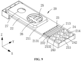
FIG. 9 is a structural schematic view of a second lower plastic member of the lower plastic assembly inFIG. 3 . -
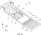
FIG. 10 is a schematic structural view of the second lower plastic member of the lower plastic assembly inFIG. 9 from another view. -
FIG. 11 is a schematic structural view illustrating the upper cover, the first lower plastic member, and second lower plastic member inFIG. 3 that are assembled together. - Reference signs: 1000-energy storage apparatus, 100-end cover assembly, 200-electrode assembly, 30-lower plastic assembly, 40-upper cover, 41-upper cover body, 411-front face, 412-back face, 413-through groove, 414-first protrusion, 4141-first upper wall, 415-second protrusion, 4151-second upper wall, 417-first mounting recess, 418-second mounting recess, 42-positive-post through-hole, 43-negative-post through hole, 44-explosion-proof valve, 45-first flipping sheet, 46-second flipping sheet, 47-liquid injection hole, 10-first lower plastic member, 11-first-lower-plastic-member body, 111-first upper surface, 112-first lower surface, 113-first through groove, 1131-first side wall, 1132-second side wall, 117-first receiving recess, 118-recess, 1181-lower wall, 1182-peripheral wall, 1183-wall surface, 119-cutout, 1191-first part, 1192-second part, 12-first snapped protrusion, 13-first grid, 131-connecting portion, 1311-guiding slope, 132-first rib, 14-first liquid-injection through-hole, 15-first gas hole, 16-first protective grid, 17-first terminal-post through-hole, 18-first recess, 20-second lower plastic member, 21-second-lower-plastic-member body, 211-second upper surface, 212-second lower surface, 213-second through groove, 2131-third side wall, 2132-fourth side wall, 214-third through groove, 215-gas-hole, 217-second receiving recess, 22-second snapped protrusion, 23-second grid, 232-second rib, 24-third grid, 242-first divider, 243-second divider, 25-second gas hole, 26-second protective grid, 27-second terminal-post through-hole, 28-second recess, 29-protrusion, A-arched grid.
- Technical solutions in implementations of the disclosure are clearly and completely described in the following with reference to accompanying drawings in the implementations of the disclosure. Apparently, the described implementations are merely part rather than all of implementations of the disclosure. All other implementations obtained by those of ordinary skill in the art based on the implementations of the disclosure without creative efforts are within the protection scope of the disclosure.
- Referring to
FIG. 1 andFIG. 2 ,FIG. 1 is a schematic structural view of an energy storage apparatus provided in implementations of the disclosure, andFIG. 2 is a schematic structural view of an end cover assembly of the energy storage apparatus inFIG. 1 . - For the convenience of illustration, a length direction of an end cover assembly illustrated in
FIG. 1 is defined as an X-axis direction, a width direction of the end cover assembly is defined as a Y-axis direction, a height direction of the end cover assembly is defined as a Z-axis direction, and the X-axis direction, the Y-axis direction, and the Z-axis direction are perpendicular to each other. Terms such as "upper" and "lower" for describing implementations of the disclosure are described based on orientations as illustrated inFIG. 1 of the specification. "Upper" refers to a direction towards a positive direction of the Z-axis, and "lower" refers to a direction towards a negative direction of the Z-axis, which do not form a limitation to the energy storage apparatus in practical application scenarios. - An
end cover assembly 100 is provided in the disclosure. Theend cover assembly 100 includes a lowerplastic assembly 30. Anenergy storage apparatus 1000 including theend cover assembly 100 and an electric device (not illustrated) using theenergy storage apparatus 1000 are further provided in the disclosure. In an implementation, as an example, theenergy storage apparatus 1000 is a battery. Theenergy storage apparatus 1000 includes a housing (not illustrated), theend cover assembly 100, and anelectrode assembly 200. Theend cover assembly 100 is mounted at one end of theelectrode assembly 200 where a tab (not illustrated) is disposed. The housing encloses a periphery and a bottom of theelectrode assembly 200 and is in sealed connection with theend cover assembly 100. The electric device may be an unmanned aerial vehicle or an electric vehicle, etc. It can be understood that a practical application scenario of theenergy storage apparatus 1000 provided in the implementations of the disclosure may be, but is not limited to, the listed products, and may also be other application scenarios, which is not strictly limited in the implementations of the disclosure. - Referring to
FIG. 1 ,FIG. 3 , andFIG.4 , theend cover assembly 100 includes the lowerplastic assembly 30 and anupper cover 40 stacked with the lowerplastic assembly 30. The lowerplastic assembly 30 is located between theelectrode assembly 200 and theupper cover 40. In the implementations, theupper cover 40 may be a polished aluminum piece, and the lowerplastic assembly 30 may be made of plastic and insulated. - In the implementations, the lower
plastic assembly 30 includes a first lowerplastic member 10 and a second lowerplastic member 20. The first lowerplastic member 10 and the second lowerplastic member 20 are arranged side by side at one side of theupper cover 40 in a length direction (i.e., X-axis direction) of theend cover assembly 100. The first lowerplastic member 10 and the second lowerplastic member 20 are stacked with theupper cover 40. A sum of a length of the first lowerplastic member 10 and a length of the second lowerplastic member 20 is equal to a length of theupper cover 40. Each of a width of the firstlower plastic member 10 and a width of the secondlower plastic member 20 is substantially equal to a width of theupper cover 40, and a certain tolerance range is allowed. - In the implementations, the
upper cover 40 includes anupper cover body 41, an explosion-proof valve 44, afirst flipping sheet 45, and asecond flipping sheet 46. Theupper cover body 41 further defines a positive-post through-hole 42, a negative-post throughhole 43, and aliquid injection hole 47. The positive-post through-hole 42, thefirst flipping sheet 45, theliquid injection hole 47, the explosion-proof valve 44, thesecond flipping sheet 46, and the negative-post throughhole 43 are sequentially arranged at intervals in the X-axis direction (that is, a length direction of the upper cover body 41). - Specifically, the
upper cover body 41 is an elongated thin plate, includes afront face 411 and aback face 412 opposite to thefront face 411, and defines afirst mounting recess 417 and asecond mounting recess 418. Thefirst mounting recess 417 and thesecond mounting recess 418 are located at opposite ends (arranged along the X-axis direction) of theback face 412 of theupper cover body 41. Thefirst mounting recess 417 and thesecond mounting recess 418 are rectangular. Thefirst mounting recess 417 is recessed from theback face 412 towards thefront face 411 and forms afirst protrusion 414 at thefront face 411. Thesecond mounting recess 418 is recessed from theback face 412 towards thefront face 411 and forms asecond protrusion 415 at thefront face 411. - The
first protrusion 414 has a firstupper wall 4141. The firstupper wall 4141 exceeds thefront face 411 and is parallel to thefront face 411, and a certain tolerance range is allowed. Actually, a back face of the firstupper wall 4141 serves as a lower wall of thefirst mounting recess 417. The positive-post through-hole 42 extends through the firstupper wall 4141. A through hole (not illustrated) is defined at one side of the firstupper wall 4141 where the positive-post through-hole 42 is located. Thefirst flipping sheet 45 is circular, and is accommodated in the through hole and welded with a hole wall of the through hole. - The
second protrusion 415 has a secondupper wall 4151. The secondupper wall 4151 exceeds thefront face 411 and is parallel to thefront face 411, and a certain tolerance range is allowed. Actually, a back face of the secondupper wall 4151 serves as a lower wall of thesecond mounting recess 418. The negative-post throughhole 43 extends through the secondupper wall 4151. A through-hole (not illustrated) is defined at one side of the secondupper wall 4151 where the negative-post throughhole 43 is located. Thesecond flipping sheet 46 is a circular thin sheet, and is accommodated in the through-hole and soldered with a hole wall of the through-hole. - A through
groove 413 is further defined at a middle portion of theupper cover body 41 and extends through theback face 412 and thefront face 411, and the throughgroove 413 is located between thefirst mounting recess 417 and thesecond mounting recess 418. The explosion-proof valve 44 is accommodated in the throughgroove 413 and is welded with a wall of the throughgroove 413. When an internal pressure of theenergy storage apparatus 1000 is excessively high, the explosion-proof valve 44 will automatically open to relieve the pressure, thereby avoiding an explosion. - It can be understood that, the positive-post through-
hole 42 is located at one end of theupper cover body 41 and the negative-post throughhole 43 is located at the other end of theupper cover body 41, and a positive post may extend through the positive-post through-hole 42 and a negative post of the battery may extend through the negative-post throughhole 43. Thefirst flipping sheet 45 is disposed at one side of the positive-post through-hole 42 close to the explosion-proof valve 44, and thesecond flipping sheet 46 is disposed at one side of the negative-post throughhole 43 close to the explosion-proof valve 44. When the internal pressure of theenergy storage apparatus 1000 is relatively high, thefirst flipping sheet 45 or thesecond flipping sheet 46 will bend and deform upwards to abut against a lower surface of a metal block, so that the battery is short-circuited to provide a protective effect. - The
liquid injection hole 47 is located between thefirst flipping sheet 45 and the explosion-proof valve 44. During liquid injection for a power battery, an electrolyte is injected into the battery through theliquid injection hole 47 on theupper cover 40. - Referring to
FIG. 5 andFIG. 6 together, in the implementations, the firstlower plastic member 10 includes a first-lower-plastic-member body 11 and a first snappedprotrusion 12. In a thickness direction (i.e., Z-axis direction) of the firstlower plastic member 10, the first-lower-plastic-member body 11 is a substantially rectangular thin plate. The first-lower-plastic-member body 11 has a firstupper surface 111 and a firstlower surface 112 opposite to the firstupper surface 111. Specifically, the first snappedprotrusion 12 protrudes from the firstupper surface 111 of the first-lower-plastic-member body 11 and is located at one end of the first-lower-plastic-member body 11 in a length direction (i.e., X-axis direction) of the firstlower plastic member 10. The first-lower-plastic-member body 11 further defines a first throughgroove 113 at one end away from the first snappedprotrusion 12. The first throughgroove 113 is rectangular and extends through the firstupper surface 111 and the firstlower surface 112. The first throughgroove 113 has afirst side wall 1131 and asecond side wall 1132 that are opposite to each other in the length direction (i.e., X-axis direction) of the firstlower plastic member 10. The first throughgroove 13 is configured to direct pressure-gas generated in theenergy storage apparatus 1000 to the explosion-proof valve 44. - In the implementations, the first
lower plastic member 10 further includes afirst grid 13 and a firstprotective grid 16. The first-lower-plastic-member body 11 defines a first liquid-injection through-hole 14, a first terminal-post through-hole 17, and afirst recess 18. Thefirst grid 13, the first liquid-injection through-hole 14, thefirst recess 18, and the first terminal-post through-hole 17 are sequentially arranged on the first-lower-plastic-member body 11 in the length direction (i.e., X-axis direction) of the firstlower plastic member 10. The first liquid-injection through-hole 14 extends through the first-lower-plastic-member body 11 and is located at one end of the first-lower-plastic-member body 11. - In the implementations, the
first grid 13 is formed in the first throughgroove 113 and includes a connectingportion 131 and multiplefirst ribs 132, where the multiplefirst ribs 132 are arranged side by side and at intervals. The connectingportion 131 is elongated and extends in a width direction (i.e., Y-axis direction) of the firstlower plastic member 10. One side of the connectingportion 131 is fixed to thefirst side wall 1131 of the first throughgroove 113, and the other side of the connectingportion 131 extends towards thesecond side wall 1132 at one end of the first-lower-plastic-member body 11. The connectingportion 131 includes a guidingslope 1311. One end of each of the multiplefirst ribs 132 is connected to a face of the connectingportion 131 away from thefirst side wall 1131, the other end of each of the multiplefirst ribs 132 is fixed to thesecond side wall 1132 of the first throughgroove 113, and the multiplefirst ribs 132 extend towards thesecond side wall 1132 located at the end of the first-lower-plastic-member body 11. The guidingslope 1311 of the connectingportion 131 and the multiplefirst ribs 132 are inclined towards the firstlower surface 112, and specifically, each of the guidingslope 1311 and the multiplefirst ribs 132 is inclined towards the firstlower surface 112 from a side away from thesecond side wall 1132. An included angle between the firstupper surface 111 and each of thefirst ribs 132 is an obtuse angle. Each two adjacentfirst ribs 132 define a first gap therebetween and the first gap is elongated, and gas can flow through the first gap. - In the implementations, a width k of the first gap in the length direction of the first
lower plastic member 10 is 0.4 mm to 2 mm, and the width k of the first gap is a distance between each two adjacentfirst ribs 132. In the width direction of the firstlower plastic member 10, a first gap is also defined between the outermostfirst rib 132 among the multiplefirst ribs 132 and a wall of the first throughgroove 113, that is, the first gap is also defined between the outermostfirst rib 132 and the first-lower-plastic-member body 11. - The first terminal-post through-
hole 17 is circular and extends through the firstupper surface 111 and the firstlower surface 112. The first terminal-post through-hole 17 is defined on the first snappedprotrusion 12 and is close to one end of the first-lower-plastic-member body 11. The positive post can pass through the first terminal-post through-hole 17. - The
first recess 18 is substantially rectangular, and is recessed from the firstlower surface 112 towards the firstupper surface 111 in a thickness direction of the first-lower-plastic-member body 11. Thefirst recess 18 corresponds to the first snappedprotrusion 12, and is located between the first liquid-injection through-hole 14 and the first terminal-post through-hole 17. - The
first gas hole 15 is defined on a lower wall of thefirst recess 18, and extends through a surface of the lower wall of thefirst recess 18 and the firstupper surface 111. Thefirst gas hole 15 is configured to direct the pressure-gas generated in theenergy storage apparatus 1000 to thefirst flipping sheet 45. - The first
protective grid 16 is a grid-shaped thin plate and located at one side of the firstlower surface 112 of the first-lower-plastic-member body 11. Specifically, the firstprotective grid 16 is formed in thefirst recess 18. The firstprotective grid 16 may be plastic, and may be integrally formed with the firstlower plastic member 10. In the thickness direction (i.e., Z-axis direction) of the first-lower-plastic-member body 11, the firstprotective grid 16 covers thefirst gas hole 15. In the thickness direction (i.e., Z-axis direction) of the first-lower-plastic-member body 11, an orthographic projection of the firstprotective grid 16 is larger than an orthographic projection of thefirst gas hole 15. The firstprotective grid 16 has an exhaust region (not illustrated), and the exhaust region is composed of multiple gaps and is in communication with thefirst gas hole 15. - The first-lower-plastic-
member body 11 further defines afirst receiving recess 117 that is recessed from the firstlower surface 112 and located at one end away from the first liquid-injection through-hole 14. The first terminal-post through-hole 17 extends through a lower wall of thefirst receiving recess 117 in the thickness direction (i.e., Z-axis direction) of the first-lower-plastic-member body 11. Thefirst receiving recess 117 is adjacent to the firstprotective grid 16. Referring toFIG. 7 andFIG. 8 , the first liquid-injection through-hole 14 is close to thefirst grid 13 and is configured to cooperate with theliquid injection hole 47 to enable the electrolyte to flow into theelectrode assembly 200. A diameter of the first liquid-injection through-hole 14 is greater than a diameter of theliquid injection hole 47. In the implementations, the first-lower-plastic-member body 11 further defines arecess 118. Therecess 118 is recessed from the firstupper surface 111 and is adjacent to the first throughgroove 113. Specifically, therecess 118 is circular. Therecess 118 has alower wall 1181 and aperipheral wall 1182. Theperipheral wall 1182 surrounds a periphery of thelower wall 1181. A diameter of thelower wall 1181 is greater than the diameter of the first liquid-injection through-hole 14. Awall surface 1183 of theperipheral wall 1182 is a slope, and a diameter of theperipheral wall 1182 at one side on the firstupper surface 111 is greater than a diameter of theperipheral wall 1182 at the other side connected to thelower wall 1181. It can be understood that theperipheral wall 1182 gradually reduces in diameter in a direction from the firstupper surface 111 to thelower wall 1181. Thewall surface 1183 of theperipheral wall 1182 is inclined from the firstupper surface 111 towards thelower wall 1181. An included angle between thewall surface 1183 of theperipheral wall 1182 and the firstupper surface 111 is an obtuse angle. The included angle between thewall surface 1183 of theperipheral wall 1182 and the firstupper surface 111 ranges from 95° to 160°. In an implementation, the included angle is 120°. In another implementation, thewall surface 1183 of theperipheral wall 1182 may also be planar, i.e., perpendicular or substantially perpendicular to the firstupper surface 111. - In the thickness direction of the first-lower-plastic-
member body 11, a depth s of therecess 118 ranges from 0.8 mm to 6 mm. In an implementation, the depth s of therecess 118 is 1.2 mm. The depth s of therecess 118 is greater than 0.8 mm, and thus therecess 118 can sufficiently accommodate theliquid injection hole 47 protruding downwards from theupper cover 40. The depth s of therecess 118 is smaller than 6 mm, and thus a lower surface of thelower wall 1181 can be prevented from protruding beyond a thickest part of the first lowerplastic member rubber 10, thereby avoiding thelower wall 1181 from interfering with theelectrode assembly 200 below thelower wall 1181, and a reduction in an energy density of theenergy storage apparatus 1000. In the thickness direction (i.e., Z-axis direction) of the first-lower-plastic-member body 11, the first liquid-injection through-hole 14 extends through thelower wall 1181 of therecess 118 and the firstlower surface 112. In the implementations, therecess 118 is recessed from the firstupper surface 111 towards the firstlower surface 112, and forms a protrusion on the firstlower surface 112, that is, theperipheral wall 1182 and thelower wall 1181 exceeds the firstlower surface 112. - The first liquid-injection through-
hole 14 is defined on thelower wall 1181 of therecess 118, and thewall surface 1183 of theperipheral wall 1182 of therecess 118 is inclined, such that during liquid injection the electrolyte in therecess 118 can flow into the first liquid-injection through-hole 14 along thewall surface 1183, which can prevent the electrolyte from spattering onto the firstupper surface 111 of the first-lower-plastic-member body 11, thereby avoiding waste of the electrolyte. It should be understood that, in other implementations, therecess 118 may also be of other shapes, such as square. - In the implementations, the
peripheral wall 1182 of therecess 118 defines acutout 119 that is rectangular and extends through the firstupper surface 111 and the firstlower surface 112 of the first-lower-plastic-member body 11. Therectangular cutout 119 can facilitate flow of the electrolyte and prevent a foreign object from blocking the first liquid-injection through-hole 14 when flowing through thecutout 119. Thecutout 119 is defined between the first liquid-injection through-hole 14 and the first throughgroove 113, and is in communication the first throughgroove 113 and therecess 118. Specifically, thecutout 119 includes afirst part 1191 and asecond part 1192 that is located between thefirst part 1191 and the multiplefirst ribs 132. Thefirst part 1191 extends through the wall surface of theperipheral wall 1182 in the length direction (i.e., X-axis direction) of the firstlower plastic member 10 and is in communication with thesecond part 1192. Thefirst part 1191 extends from the firstupper surface 111 towards the firstlower surface 112 and is in communication with therecess 118 recessed from the firstupper surface 111, such that the electrolyte around therecess 118 is easy to enter thecutout 119. Thesecond part 1192 is elongated and extends in the width direction (i.e., Y-axis direction) of the firstlower plastic member 10. Thesecond part 1192 extends through the firstupper surface 111 and the firstlower surface 112, and is located at one side of the first throughgroove 113 where the connectingportion 131 is disposed. Thesecond part 1192 extends through part of the guidingslope 1311 of the connectingportion 131, which may be understood as that thesecond part 1192 is in communication with the first throughgroove 113. In the length direction of the first-lower-plastic-member body 11, a distance L1 between one side of thecutout 119 away from therecess 118 and a center of therecess 118 ranges from 2.8 mm to 8.4 mm. A width h of thecutout 119 ranges from 0.8 mm to 3.2 mm, and specifically, the width h may be 1.4 mm. A length d of thecutout 119 ranges from 4 mm to 10 mm, and specifically, the length d may be 6.5 mm. In an implementation, the distance L1 between the one side of thecutout 119 away from therecess 118 and the center of therecess 118 is 5.25 mm. The distance between the one side of thecutout 119 away from therecess 118 and the center of therecess 118 is greater than 2.8 mm, such that thecutout 119 will not intersect with the first liquid-injection through-hole 14, and can be in direct communication with the first liquid-injection through-hole 14, thereby avoiding a reduction in structural strength. The distance between the one side of thecutout 119 away from therecess 118 and the center of therecess 118 is less than 8.4 mm, such that thecutout 119 can intersect with the wall surface of theperipheral wall 1182 of therecess 118. A ratio of the length d of thecutout 119 to a width H of the first-lower-plastic-member body 11 ranges from 0.15 to 0.4, and specifically, the ratio may be 0.25. The ratio of the length d of thecutout 119 to the width H of the first-lower-plastic-member body 11 is greater than 0.15, such that thecutout 119 has a sufficient area for the electrolyte to flow quickly. The ratio of the length d of thecutout 119 to the width H of the first-lower-plastic-member body 11 is less than 0.4, avoiding an excessive large length of thecutout 119, and thus the first-lower-plastic-member body 11 can have sufficient strength and accordingly breakage of the first-lower-plastic-member body 11 can be avoided. A ratio of an area of thecutout 119 to an area of the first liquid-injection through-hole 14 ranges from 0.65 to 1.35, such that thecutout 119 has a sufficient area for the electrolyte to flow quickly. - With the
cutout 119, when the electrolyte spatters onto therecess 118 and the firstupper surface 111 around the first liquid-injection through-hole 14, the electrolyte in therecess 118 can directly flow downwards through thecutout 119 to theelectrode assembly 200, and at the same time, the electrolyte flows along the guidingslope 1311 of the connectingportion 131 of thefirst grid 13 into the multiple first gaps between the multiplefirst ribs 132, and eventually flows through the multiple first gaps to theelectrode assembly 200. Furthermore, thecutout 119 can serve as a second flow channel. When the first liquid-injection through-hole 14 is blocked by a foreign object, such as a broken tab or an insulation film, the electrolyte can flow directly downwards through thecutout 119 to theelectrode assembly 200. That is, when the first liquid-injection through-hole 14 is blocked or is flow-limited by a foreign object, the electrolyte can also flow through thecutout 119 directly downwards to theelectrode assembly 200. When both the first liquid-injection through-hole 14 and thecutout 119 are blocked, the electrolyte can also flow along the guidingslope 1311 of the connectingportion 131, and eventually flow through the multiple first gaps between the multiplefirst ribs 132 into theelectrode assembly 200. Therefore, with the aid of thecutout 119, there will be no residual electrolyte around the first liquid-injection through-hole 14 and therecess 118 will not be completely filled with electrolyte, avoiding electrolyte overflow that may cause a waste of the electrolyte and a corrosion of an outer surface. Both thecutout 119 and the first liquid-injection through-hole 14 can enable the electrolyte to flow into theelectrode assembly 200, and therefore, thecutout 119 can also serve to divert electrolyte flow to prevent excessive electrolyte flow at the first liquid-injection through-hole 14 and to accelerate an injection speed of the electrolyte. - It can be understood that, during backflow of the electrolyte due to an excessive electrolyte flow or a partial blockage at the first liquid-injection through-
hole 14, the electrolyte may also flow downwards through thecutout 119 to theelectrode assembly 200. Thecutout 119 can also be used for discharging of gas in theelectrode assembly 200, thereby avoiding an excessive gas pressure in theelectrode assembly 200, and thus a misoperation of the explosion-proof valve, which may cause a failure of the battery, can be avoided. It can be understood that in other implementations, thecutout 119 can be of other shapes, such as square, circle, oval, prism, etc. - Referring to
FIG. 9 andFIG. 10 together, in the implementations, the secondlower plastic member 20 includes a second-lower-plastic-member body 21 and a second snappedprotrusion 22. In a thickness direction (i.e., Z-axis direction) of the second-lower-plastic-member body 21, the second-lower-plastic-member body 21 is a substantially rectangular thin plate and has a secondupper surface 211 and a secondlower surface 212 opposite to the secondupper surface 211. Specifically, the second snappedprotrusion 22 protrudes from the secondupper surface 211 of the second-lower-plastic-member body 21 and is located at one end of the second-lower-plastic-member body 21 in the X-axis direction. - The second-lower-plastic-
member body 21 further defines a second throughgroove 213 and a third throughgroove 214 at one end away from the second snappedprotrusion 22, and the second throughgroove 213 and the third throughgroove 214 are located side by side at intervals along the X-axis direction. The second throughgroove 213 is rectangular and extends through the secondupper surface 211 and the secondlower surface 212. The second throughgroove 213 has athird side wall 2131 and afourth side wall 2132, which are opposite to each other in the length direction (i.e., X-axis direction) of the second-lower-plastic-member body 21. The third throughgroove 214 is rectangular and extends through the secondupper surface 211 and the secondlower surface 212. The second throughgroove 213 and the third throughgroove 214 are both configured to guide pressure-gas generated in theenergy storage apparatus 1000 to the explosion-proof valve 44. - In the implementations, the second
lower plastic member 20 further includes asecond grid 23, athird grid 24, and a secondprotective grid 26. The second-lower-plastic-member body 21 defines asecond gas hole 25, a second terminal-post through-hole 27, and asecond recess 28. Thethird grid 24, thesecond grid 23, thesecond recess 28, and the second terminal-post through-hole 27 are sequentially located on the second-lower-plastic-member body 21 in the length direction (i.e., X-axis direction) of the secondlower plastic member 20. - The
second grid 23 is formed in the second throughgroove 213 and includes multiplesecond ribs 232 arranged side by side at intervals. One end of each of the multiplesecond ribs 232 is fixed to thethird side wall 2131 of the second throughgroove 213, and the multiplesecond ribs 232 extend towards thefourth side wall 2132 located at one end of the second-lower-plastic-member body 21. The other end of each of the multiplesecond ribs 232 is fixed to thefourth side wall 2132 of the second throughgroove 213, and is inclined towards the secondlower surface 212. An included angle between each of the multiplesecond ribs 232 and the secondupper surface 211 is an obtuse angle. Each two adjacentsecond ribs 232 defines a second gap (not illustrated) therebetween and the second gap is elongated, and gas can flow through the second gap. In the width direction (i.e., Y-axis direction) of the secondlower plastic member 20, second gaps are also defined between two outermostsecond ribs 232 among the multiplesecond ribs 232 and two opposite walls of the second throughgroove 213, that is, the second gap is also defined between each of the outermostsecond ribs 232 and the second-lower-plastic-member body 21. - The
third grid 24 is formed in the third throughgroove 214 and includes multiplefirst dividers 242 and asecond divider 243. The multiplefirst dividers 242 are arranged side by side at intervals in the width direction (i.e., Y-axis direction) of the secondlower plastic member 20. Each of the multiplefirst dividers 242 is connected to two opposite side walls of the third throughgroove 214 in the length direction (i.e., X-axis direction) of the secondlower plastic member 20. Thesecond divider 243 extends through the multiplefirst dividers 242 in the width direction (i.e., Y-axis direction) of the secondlower plastic member 20, and connects two opposite side walls of the third throughgroove 214 in the width direction (i.e., Y-axis direction) of the secondlower plastic member 20. It can be understood that the multiplefirst dividers 242 and thesecond divider 243 cooperate to define multiple gas-holes 215 in the third throughgroove 214. In the implementations, the number of thesecond dividers 243 is one, and in other implementations, the number of thesecond divider 243 may be two or more. - The second terminal-post through-
hole 27 is circular and extends through the secondupper surface 211 and the secondlower surface 212. The second terminal-post through-hole 27 is located on the second snappedprotrusion 22 and is close to one end of the second-lower-plastic-member body 21. The negative pole can pass through the second terminal-post through-hole 27. - The
second recess 28 is substantially rectangular, and is recessed from the secondlower surface 212 towards the secondupper surface 211 in the thickness direction of the second-lower-plastic-member body 21. Thesecond recess 28 corresponds to the second snappedprotrusion 22 and is close to one end of thesecond grid 23. - The
second gas hole 25 is defined on a lower wall of thesecond recess 28 and extends through a surface of the lower wall of thesecond recess 28 and the secondupper surface 211. Thesecond gas hole 25 is configured to direct the pressure-gas generated in theenergy storage apparatus 1000 to thesecond flipping sheet 46. - The second
protective grid 26 is a grid-shaped thin plate and located at one side of the secondlower surface 212 of the second-lower-plastic-member body 21. Specifically, the secondprotective grid 26 is formed in thesecond recess 28. The secondprotective grid 26 may be plastic, and may be integrally formed with the secondlower plastic member 20. In the thickness direction (i.e., Z-axis direction) of the second-lower-plastic-member body 21, the secondprotective grid 26 covers thesecond gas hole 25. In the thickness direction (i.e., Z-axis direction) of the second-lower-plastic-member body 21, an orthographic projection of the secondprotective grid 26 is larger than an orthographic projection of thesecond gas hole 25. The secondprotective grid 26 has an exhaust region (not illustrated), and the exhaust region is composed of multiple gaps and is in communication with thesecond gas hole 25. - The second-lower-plastic-
member body 21 further defines asecond receiving recess 217. Thesecond receiving recess 217 is recessed from the secondlower surface 212 and is located at one end of the secondlower surface 212 away from the second throughgroove 213. The second terminal-post through-hole 27 extends through a lower wall of thesecond receiving recess 217 in the thickness direction (i.e., Z-axis direction) of the second-lower-plastic-member body 21. Thesecond receiving recess 217 is adjacent to the secondprotective grid 26. - Referring to
FIG. 11, FIG. 11 is a schematic structural view illustrating theupper cover 40, the firstlower plastic member 10, and secondlower plastic member 20 that are assembled together. The firstlower plastic member 10 is stacked on one side of theupper cover 40 where theliquid injection hole 47 is defined. The firstupper surface 111 of the firstlower plastic member 10 faces and is attached to theback face 412 of theupper cover 40. The first snappedprotrusion 12 is inserted into thefirst mounting recess 417. The first snappedprotrusion 12 can be snapped into thefirst mounting recess 417 to achieve mutual positioning. In a thickness direction (i.e., Z-axis direction) of theupper cover 40, the first terminal-post through-hole 17 of the firstlower plastic member 10 faces and is in communication with the positive-post through-hole 42 of theupper cover 40. Thefirst gas hole 15 of the firstlower plastic member 10 faces the through hole of theupper cover 40 and thefirst flipping sheet 45. The first liquid-injection through-hole 14 of the firstlower plastic member 10 faces and is in communication with theliquid injection hole 47 of theupper cover 40. Thefirst grid 13 of the firstlower plastic member 10 faces part of the explosion-proof valve 44 of theupper cover 40. Since the diameter of the first liquid-injection through-hole 14 of the firstlower plastic member 10 is greater than the diameter of theliquid injection hole 47 of theupper cover 40, during injection of the electrolyte into theelectrode assembly 200 through theliquid injection hole 47 and the first liquid-injection through-hole 14 coaxial with theliquid injection hole 47, the electrolyte can be prevented from spattering onto the firstupper surface 111 of the firstlower plastic member 10, and a stay time of the electrolyte around the first liquid-injection through-hole 14 of the firstlower plastic member 10 can also be reduced, and thus the injection speed of the electrolyte can be accelerated. - The second
lower plastic member 20 is stacked on theback face 412 of theupper cover 40, one end of the secondlower plastic member 20 abuts against one end of the firstlower plastic member 10, and the length direction of the secondlower plastic member 20 and the length direction of the firstlower plastic member 10 are the same as the length direction of theupper cover 40. Specifically, the secondupper surface 211 of the secondlower plastic member 20 faces and is attached to theback face 412 of theupper cover 40, and the second snappedprotrusion 22 is inserted into thesecond mounting recess 418. The second snappedprotrusion 22 can be snapped into thesecond mounting recess 418 to achieve mutual positioning. In the thickness direction (i.e., Z-axis direction) of theupper cover 40, the second terminal-post through-hole 27 of the secondlower plastic member 20 faces and is in communication with the negative-post throughhole 43 of theupper cover 40. Thesecond gas hole 25 of the secondlower plastic member 20 faces the through hole of theupper cover 40 and thesecond flipping sheet 46. Thesecond grid 23 and thethird grid 24 of the secondlower plastic member 20 face part of the explosion-proof valve 44 of theupper cover 40. - In this case, the
first grid 13 of the firstlower plastic member 10 abuts against thethird grid 24, and in the length direction (i.e., X-axis direction) of theupper cover 40, thesecond grid 23, thethird grid 24, and thefirst grid 13 are arranged in sequence. In the length direction (i.e., X-axis direction) of theupper cover 40, the sum of the length of thesecond grid 23, the length of thethird grid 24, and the length of thefirst grid 13 is greater than or equal to the length of the explosion-proof valve 44 of theupper cover 40. In the width direction (i.e., Y-axis direction) of theupper cover 40, each of the width of thesecond grid 23, the width of thethird grid 24, and the width of thefirst grid 13 is greater than or equal to the width of the explosion-proof valve 44 of theupper cover 40, ensuring that thesecond grid 23, thethird grid 24, and thefirst grid 13 can cooperate to completely cover the explosion-proof valve 44, which can maximize a space for air gathering below the explosion-proof valve 44, and improve an uniformity of force applied to the explosion-proof valve 44. - A tab or a blue film is prone to break to generate fragments during transportation and use of the
energy storage apparatus 1000. Thefirst grid 13, thesecond grid 23, and thethird grid 24 are respectively disposed in the first throughgroove 113, the second throughgroove 213, and the third throughgroove 214, flowing of the fragments of the tab or the blue film to a position under the explosion-proof valve 44, which may block a gas channel and consequently cause an explosion-proof failure, can be prevented. In addition, floating of the tab to the explosion-proof valve 44, which may cause electrical connection between the electrode and theupper cover 40, and result in a short circuit and consequently failure of theenergy storage apparatus 1000, can be prevented. The firstprotective grid 16 and the secondprotective grid 26 are respectively disposed at thefirst gas hole 15 and thesecond gas hole 25, flowing of the fragments of the tab or the blue film to a position under thefirst flipping sheet 45 and thesecond flipping sheet 46, which may block the gas channel, can be prevented, and furthermore, functions of thefirst flipping sheet 45 and thesecond flipping sheet 46 can be ensured, that is, when being subjected to the gas pressure inside theenergy storage apparatus 1000, thefirst flipping sheet 45 and thesecond flipping sheet 46 can deform to short-circuit the electrodes of theelectrode assembly 200 to theupper cover 40, so that theenergy storage apparatus 1000 can be short-circuited, thereby protecting theenergy storage apparatus 1000. - Referring to
FIG. 11 again, a thickness of the secondlower plastic member 20 at a position where the third throughgroove 214 is defined is greater than a thickness of the secondlower plastic member 20 at other positions. Specifically, aprotrusion 29 is disposed on the secondlower surface 212 of the second-lower-plastic-member body 21. In the thickness direction (i.e., Z-axis direction) of the secondlower plastic member 20, the third throughgroove 214 extends through the secondupper surface 211 and theprotrusion 29. Thethird grid 24 is disposed in the third throughgroove 214, and a thickness of thethird grid 24 is greater than a thickness of the second-lower-plastic-member body 21. - It can be understood that the first
lower plastic member 10 includes thefirst grid 13, and thefirst grid 13 defines the first gaps extending through the firstupper surface 111 and the firstlower surface 112. The secondlower plastic member 20 includes thesecond grid 23, thethird grid 24 close to thesecond grid 23, and theprotrusion 29 protruding from the secondlower surface 212. Thesecond grid 23 defines the second gaps extending through the secondupper surface 211 and the secondlower surface 212. Thethird grid 24 has the gas-hole 215 extending through the secondupper surface 211 and theprotrusion 29. - The end of each of the multiple
first ribs 132 of thefirst grid 13 fixed to thesecond side wall 1132 is inclined towards the firstlower surface 112. The end of each of the multiplesecond ribs 232 of thesecond grid 23 fixed to thefourth side wall 2132 is inclined towards the secondlower surface 212. Thethird grid 24 extends through the secondupper surface 211 and theprotrusion 29, and has a relatively large thickness. That is, in the length direction (i.e., X-axis direction) of the firstlower plastic member 10, the multiplefirst ribs 132 are inclined towards the firstlower surface 112, and in the length direction (i.e., X-axis direction) of the secondlower plastic member 20, the multiplesecond ribs 232 are inclined towards the secondlower surface 212. When the firstlower plastic member 10 abuts against the secondlower plastic member 20, an inclined end of each of the multiplefirst ribs 132 and an inclined end of each of the multiplesecond ribs 232 are all away from thethird grid 24. Therefore, thefirst grid 13, thesecond grid 23, and thethird grid 24 form, as a whole, an arched grid A away from the explosion-proof valve 44 of theupper cover 40 and protruding downwards (away from the upper cover 40), and the explosion-proof valve 44 faces the arched grid A in the thickness direction of theupper cover 40. Therefore, a space below the explosion-proof valve 44 can be enlarged, facilitating gas gathering, and additionally, an accommodation space for the tab is enlarged, so that the fracture of the tab can be avoided. The arched grid A as a whole can also prevent the tab from blocking the through groove from three directions, and the three directions are respectively perpendicular to thefirst grid 13, thesecond grid 23, and thethird grid 24. In addition, the arched grid A can prevent the tab from reaching below theupper cover 40 and establishing abnormal electrical connection with theupper cover 40, thereby improving the reliability. - The above implementations of the disclosure are described in detail. Principles and implementations of the disclosure are elaborated with specific examples herein. The illustration of implementations above is only used to help understanding of methods and core ideas of the disclosure. Additionally, for those skilled people in the art, according to ideas of the disclosure, there may be modifications in specific implementations and application scope. In conclusion, the content of this specification should not be construed as limiting the disclosure.
Claims (15)
- A lower plastic assembly (30) configured to be assembled with an upper cover (40) and comprising a first lower plastic member (10), whereinthe first lower plastic member (10) comprises a first-lower-plastic-member body (11), wherein the first-lower-plastic-member body (11) further comprises a first upper surface (111) and a first lower surface (112), and the first upper surface (111) is opposite to the first lower surface (112);the first-lower-plastic-member body (11) defines a first liquid-injection through-hole (14), wherein the first liquid-injection through-hole (14) extends through the first-lower-plastic-member body (11) and is located at one end of the first-lower-plastic-member body (11), a cutout (119) is defined at one side of the first liquid-injection through-hole (14) and is in direct communication with the first liquid-injection through-hole (14), and the cutout (119) extends through the first upper surface (111) and the first lower surface (112); andthe first lower plastic member (10) further comprises a recess (118), wherein the recess (118) is recessed from the first upper surface (111) and has a lower wall (1181) and a peripheral wall (1182) surrounding the lower wall (1181), and the first liquid-injection through-hole (14) extends through the lower wall (1181); the cutout (119) extends through the first upper surface (111) and the first lower surface (112) in a direction from the first upper surface (111) to the first lower surface (112) and extends through part of a wall surface of the peripheral wall (1182); the first lower plastic member (10) comprises a first grid (13), wherein the first grid (13) comprises a connecting portion (131) and defines a plurality of first gaps at one side of the connecting portion (131), the connecting portion (131) comprises a guiding slope (1311) inclined towards the plurality of first gaps, the cutout (119) is located between the connecting portion (131) and the first liquid-injection through-hole (14), and the cutout (119) extends through part of the guiding slope (1311).
- The lower plastic assembly (30) according to claim 1, whereinthe cutout (119) is rectangular, and a ratio of a length d of the cutout (119) to a width H of the first-lower-plastic-member body (11) ranges from 0.15 to 0.4; and/ora ratio of an area of the cutout (119) to an area of the first liquid-injection through-hole (14) ranges from 0.65 to 1.35.
- The lower plastic assembly (30) according to claim 1 or 2, wherein a wall surface (1183) of the peripheral wall (1182) is inclined from the first upper surface (111) towards the first liquid-injection through-hole (14), the wall surface (1183) of the peripheral wall (1182) and the first upper surface (111) defines an obtuse angle, and the wall surface (1183) of the peripheral wall (1182) and the first upper surface (111) define an included angle ranging from 95° to 160°.
- The lower plastic assembly (30) according to any one of claims 1 to 3, whereinthe first lower plastic member (10) comprises the first grid (13), wherein the first grid (13) comprises the connecting portion (131) and defines the plurality of first gaps at the one side of the connecting portion (131), the plurality of first gaps extend through the first upper surface (111) and the first lower surface (112), and the connecting portion (131) comprises the guiding slope (1311) inclined towards the plurality of first gaps; andthe cutout (119) comprises a first part (1191) and a second part (1192) in communication with the first part (1191), wherein the first part (1191) extends through part of the peripheral wall (1182), and the second part (1192) extends through part of the guiding slope (1311).
- The lower plastic assembly (30) according to any of claims 1-4, whereinthe first grid (13) comprises a plurality of first ribs (132) connected to the connecting portion (131), wherein the plurality of first ribs (132) are arranged at intervals, each two adjacent first grids (13) define one of the plurality of first gaps, and the plurality of first ribs (132) are located at one end of the first lower plastic member (10) and close to the first liquid-injection through-hole (14); andthe plurality of first ribs (132) are inclined in a direction from the first upper surface (111) to the first lower surface (112), one side of each of the plurality of first ribs (132) away from the first liquid-injection through-hole (14) is inclined towards the first lower surface (112), and each of the plurality of first ribs (132) and the first upper surface (111) define an obtuse angle.
- The lower plastic assembly (30) according to any of claims 1-5, wherein
the lower plastic assembly (30) further comprises a second lower plastic member (20), wherein the second lower plastic member (20) comprises a second-lower-plastic-member body (21), a second grid (23), and a third grid (24), wherein the second-lower-plastic-member body (21) comprises a second upper surface (211) and a second lower surface (212) opposite the first upper surface (211), the third grid (24) is located at one end of the second-lower-plastic-member body (21), and the second grid (23) is close to the third grid (24); the second grid (23) defines a plurality of second gaps extending through the second-lower-plastic-member body (21) in a thickness direction of the second-lower-plastic-member body (21), and the third grid (24) defines a plurality of gas-holes (215) extending through the second-lower-plastic-member body (21) in the thickness direction of the second-lower-plastic-member body (21). - The lower plastic assembly (30) according to claim 6, whereinthe second grid (23) comprises a plurality of second ribs (232), wherein the plurality of second gaps comprise a gap defined between each two adjacent second ribs (232) and gaps defined between the plurality of second ribs (232) and the second-lower-plastic-member body (21), and each of the plurality of second ribs (232) extends in a length direction of the second-lower-plastic-member body (21); andthe plurality of second ribs (232) are inclined in a direction from the second upper surface (211) to the second lower surface (212), one side of each of the plurality of second ribs (232) away from a middle part of the second-lower-plastic-member body (21) is inclined towards the second lower surface (212), and each of the plurality of second ribs (232) and the second upper surface (211) define an obtuse angle.
- The lower plastic assembly (30) according to claim 6 or 7, wherein the third grid (24) has a thickness greater than a thickness of the second-lower-plastic-member body (21).
- The lower plastic assembly (30) according to any one of claims 1 to 8, wherein the first lower plastic member (10) further comprises a first gas hole (15) and a first protective grid (16), wherein the first gas hole (15) extends through the first upper surface (111) and the first lower surface (112), the first protective grid (16) is located at one side of the first lower surface (112) in a thickness direction of the first lower plastic member (10) and covers the first gas hole (15), and the first protective grid (16) defines an exhaust region in communication with the first gas hole (15).
- The lower plastic assembly (30) according to any one of claims 1 to 9, wherein
the lower plastic assembly (30) comprises a second lower plastic member (20), wherein the second lower plastic member (20) comprises a second-lower-plastic-member body (21), a second gas hole (25), and a second protective grid (26), wherein the second-lower-plastic-member body (21) comprises a second upper surface (211) and a second lower surface (212); the second gas hole (25) extends through the second upper surface (211) and the second lower surface (212), the second protective grid (26) is located at one side of the second lower surface (212) in a thickness direction of the second lower plastic member (20) and covers the second gas hole (25), and the second protective grid (26) has an exhaust region in communication with the second gas hole (25). - The lower plastic assembly (30) according to any one of claims 1 to 10, wherein the recess (118) has a depth s ranging from 0.8 mm to 6 mm in a thickness direction of the first-lower-plastic-member body (11), and a distance L1 from one side of the cutout (119) away from the recess (118) to a center of the recess (118) ranges from 2.8 mm to 8.4 mm in a length direction of the first-lower-plastic-member body (11).
- The lower plastic assembly (30) according to any one of claims 1 to 5, wherein
the lower plastic assembly (30) further comprises a second lower plastic member (20), wherein the second lower plastic member (20) comprises a second-lower-plastic-member body (21), the upper cover (40) comprises an explosion-proof valve (44), the first lower plastic member (10) comprises the first grid (13), and the first grid (13) defines the plurality of first gaps extending through the first-lower-plastic-member body (11); the second lower plastic member (20) comprises a second grid (23) and a third grid (24) adjacent to the second grid (23), wherein the second grid (23) defines a plurality of second gaps extending through the second lower plastic member (20); and the third grid (24) defines a plurality of gas-holes (215) extending through the second lower plastic member (20), the second grid (23), the third grid (24), and the first grid (13) are arranged in sequence and cooperate to form an arched grid (A), wherein the explosion-proof valve (44) is opposite to the arched grid (A) in a thickness direction of the upper cover (40), and the arched grid (A) is arched in a direction away from the explosion-proof valve (44). - The lower plastic assembly (30) according to claim 12, whereinin a length direction of the upper cover (40), a sum of a length of the second grid (23), a length of the third grid (24), and a length of the first grid (13) is greater than or equal to a length of the explosion-proof valve (44) of the upper cover (40); andin a width direction of the upper cover (40), each of a width of the second grid (23), a width of the third grid (24), and a width of the first grid (13) is greater than or equal to a width of the explosion-proof valve (44) of the upper cover (40).
- An energy storage apparatus, comprising an electrode assembly (200) and the lower plastic assembly (30) of any one of claims 1 to 13, wherein the lower plastic assembly (30) is mounted at one end of the electrode assembly (200) where a tab is disposed, and the lower plastic assembly (30) faces the electrode assembly (200).
- An electric device, comprising the energy storage apparatus (1000) of claim 14, wherein the energy storage apparatus (1000) is configured for power supplying.
Applications Claiming Priority (1)
| Application Number | Priority Date | Filing Date | Title |
|---|---|---|---|
| CN202310091041.5A CN115863864B (en) | 2023-02-09 | 2023-02-09 | Lower plastic component, energy storage device and electric equipment |
Publications (3)
| Publication Number | Publication Date |
|---|---|
| EP4415155A1 true EP4415155A1 (en) | 2024-08-14 |
| EP4415155B1 EP4415155B1 (en) | 2025-03-12 |
| EP4415155B8 EP4415155B8 (en) | 2025-04-23 |
Family
ID=85657843
Family Applications (1)
| Application Number | Title | Priority Date | Filing Date |
|---|---|---|---|
| EP23213205.0A Active EP4415155B8 (en) | 2023-02-09 | 2023-11-30 | Lower plastic assembly, energy storage apparatus, and electric device |
Country Status (5)
| Country | Link |
|---|---|
| US (1) | US11984624B1 (en) |
| EP (1) | EP4415155B8 (en) |
| CN (1) | CN115863864B (en) |
| ES (1) | ES3027237T3 (en) |
| HU (1) | HUE071265T2 (en) |
Families Citing this family (5)
| Publication number | Priority date | Publication date | Assignee | Title |
|---|---|---|---|---|
| CN116315508B (en) * | 2023-05-11 | 2025-10-28 | 楚能新能源股份有限公司 | Lower plastic plate, battery cover and battery |
| CN116404321B (en) * | 2023-05-31 | 2024-03-26 | 深圳海辰储能控制技术有限公司 | Lower plastic, end cover assembly, energy storage device and electric equipment |
| CN116454529B (en) * | 2023-06-14 | 2023-09-08 | 深圳海辰储能控制技术有限公司 | Top cap subassembly and battery |
| WO2025010682A1 (en) * | 2023-07-12 | 2025-01-16 | 深圳海辰储能控制技术有限公司 | Lower plastic part, end cover assembly, energy storage apparatus, and electrical device |
| CN119994416B (en) * | 2025-04-11 | 2025-07-11 | 蜂巢能源科技股份有限公司 | Shell structure and battery |
Citations (2)
| Publication number | Priority date | Publication date | Assignee | Title |
|---|---|---|---|---|
| CN217334328U (en) * | 2022-03-10 | 2022-08-30 | 惠州亿纬锂能股份有限公司 | Cell top cover with pressure relief channel |
| KR20220151694A (en) * | 2021-04-02 | 2022-11-15 | 컨템포러리 엠퍼렉스 테크놀로지 씨오., 리미티드 | End cover assembly, battery cell, method and equipment for manufacturing battery and battery cell |
Family Cites Families (11)
| Publication number | Priority date | Publication date | Assignee | Title |
|---|---|---|---|---|
| CN207038571U (en) | 2017-08-04 | 2018-02-23 | 宁德时代新能源科技股份有限公司 | secondary battery |
| CN207938708U (en) * | 2018-04-10 | 2018-10-02 | 深圳市比克动力电池有限公司 | A power battery top cover insulation structure |
| CN208271958U (en) * | 2018-05-25 | 2018-12-21 | 安徽力信能源科技有限责任公司 | A kind of lithium ion battery structure of battery corer |
| CN209071498U (en) | 2018-12-29 | 2019-07-05 | 蜂巢能源科技有限公司 | Battery core and battery pack with it |
| CN109980173B (en) * | 2019-04-15 | 2022-04-15 | 欣旺达电子股份有限公司 | High space utilization power battery top cap and power battery |
| CN209641695U (en) * | 2019-04-16 | 2019-11-15 | 瑞浦能源有限公司 | Power battery top cover and power battery with fluid injection through-hole sealing element protection structure |
| CN111769249B (en) * | 2020-07-08 | 2025-03-21 | 江苏正力新能电池技术股份有限公司 | A lower plastic part and top cover assembly structure for power battery and power battery |
| CN216436008U (en) | 2021-11-11 | 2022-05-03 | 郑州广源电池材料有限公司 | A kind of plastic structure of lithium battery cover plate |
| CN216648454U (en) | 2021-12-31 | 2022-05-31 | 上海兰钧新能源科技有限公司 | Top cover structure and secondary battery |
| CN216958263U (en) | 2022-03-23 | 2022-07-12 | 中创新航科技股份有限公司 | Battery cover plate assembly, battery and battery pack |
| CN115632208B (en) * | 2022-11-04 | 2024-01-23 | 厦门海辰储能科技股份有限公司 | The lower plastic of the battery, the top cover assembly of the battery and the battery |
-
2023
- 2023-02-09 CN CN202310091041.5A patent/CN115863864B/en active Active
- 2023-11-29 US US18/523,735 patent/US11984624B1/en active Active
- 2023-11-30 HU HUE23213205A patent/HUE071265T2/en unknown
- 2023-11-30 ES ES23213205T patent/ES3027237T3/en active Active
- 2023-11-30 EP EP23213205.0A patent/EP4415155B8/en active Active
Patent Citations (2)
| Publication number | Priority date | Publication date | Assignee | Title |
|---|---|---|---|---|
| KR20220151694A (en) * | 2021-04-02 | 2022-11-15 | 컨템포러리 엠퍼렉스 테크놀로지 씨오., 리미티드 | End cover assembly, battery cell, method and equipment for manufacturing battery and battery cell |
| CN217334328U (en) * | 2022-03-10 | 2022-08-30 | 惠州亿纬锂能股份有限公司 | Cell top cover with pressure relief channel |
Also Published As
| Publication number | Publication date |
|---|---|
| US11984624B1 (en) | 2024-05-14 |
| EP4415155B8 (en) | 2025-04-23 |
| ES3027237T3 (en) | 2025-06-13 |
| CN115863864B (en) | 2023-05-09 |
| CN115863864A (en) | 2023-03-28 |
| HUE071265T2 (en) | 2025-08-28 |
| EP4415155B1 (en) | 2025-03-12 |
Similar Documents
| Publication | Publication Date | Title |
|---|---|---|
| EP4415155A1 (en) | Lower plastic assembly, energy storage apparatus, and electric device | |
| US11742554B2 (en) | Battery | |
| EP4167334A1 (en) | Explosion-proof sheet, top cover assembly of secondary battery, and secondary battery | |
| US20240162589A1 (en) | Lower plastic member, top cover assembly, energy storage device and electrical equipment | |
| US11710882B2 (en) | Battery | |
| US20230019890A1 (en) | Power battery and battery module | |
| EP4300664A1 (en) | Battery housing, battery, and electronic device | |
| US12009550B1 (en) | Lower plastic assembly, end cover assembly, energy-storage apparatus, and electronic device | |
| EP3331051B1 (en) | Top cover assembly for power battery and power battery having the same | |
| EP3799182A1 (en) | Secondary battery, battery pack and electric device | |
| EP4391214A1 (en) | End cover assembly, battery cell, battery and electric device | |
| EP4415131B1 (en) | Energy-storage apparatus and electricity-consumption device | |
| KR101086359B1 (en) | Cap assembly for secondary battery and secondary battery using same | |
| EP4586384A1 (en) | Lower plastic part, top cover assembly, energy storage apparatus, and electric device | |
| CN120473620B (en) | A lower plastic, end cover assembly, energy storage device and electrical equipment | |
| EP4586357A1 (en) | Casing assembly, battery cell, battery, and electrical apparatus | |
| US20250309500A1 (en) | Battery cell, battery, and electrical device | |
| US12095100B2 (en) | Energy-storage apparatus and electricity-consumption device | |
| US8017265B2 (en) | Can having electrolyte slots and lithium secondary battery using the same | |
| CN119153910A (en) | Secondary battery | |
| KR101034709B1 (en) | Secondary battery | |
| WO2024164257A1 (en) | Lower plastic assembly, energy storage apparatus, and electric device | |
| CN120473619B (en) | A lower plastic, end cover assembly, energy storage device and electrical equipment | |
| EP4415144A1 (en) | Energy storage device and power consuming device | |
| KR100467697B1 (en) | Sealed type secondary battery |
Legal Events
| Date | Code | Title | Description |
|---|---|---|---|
| PUAI | Public reference made under article 153(3) epc to a published international application that has entered the european phase |
Free format text: ORIGINAL CODE: 0009012 |
|
| STAA | Information on the status of an ep patent application or granted ep patent |
Free format text: STATUS: THE APPLICATION HAS BEEN PUBLISHED |
|
| AK | Designated contracting states |
Kind code of ref document: A1 Designated state(s): AL AT BE BG CH CY CZ DE DK EE ES FI FR GB GR HR HU IE IS IT LI LT LU LV MC ME MK MT NL NO PL PT RO RS SE SI SK SM TR |
|
| STAA | Information on the status of an ep patent application or granted ep patent |
Free format text: STATUS: REQUEST FOR EXAMINATION WAS MADE |
|
| 17P | Request for examination filed |
Effective date: 20240812 |
|
| RBV | Designated contracting states (corrected) |
Designated state(s): AL AT BE BG CH CY CZ DE DK EE ES FI FR GB GR HR HU IE IS IT LI LT LU LV MC ME MK MT NL NO PL PT RO RS SE SI SK SM TR |
|
| GRAP | Despatch of communication of intention to grant a patent |
Free format text: ORIGINAL CODE: EPIDOSNIGR1 |
|
| STAA | Information on the status of an ep patent application or granted ep patent |
Free format text: STATUS: GRANT OF PATENT IS INTENDED |
|
| RIC1 | Information provided on ipc code assigned before grant |
Ipc: H01M 50/16 20210101ALI20240924BHEP Ipc: H01M 50/15 20210101ALI20240924BHEP Ipc: H01M 50/609 20210101AFI20240924BHEP |
|
| INTG | Intention to grant announced |
Effective date: 20241008 |
|
| GRAS | Grant fee paid |
Free format text: ORIGINAL CODE: EPIDOSNIGR3 |
|
| GRAA | (expected) grant |
Free format text: ORIGINAL CODE: 0009210 |
|
| STAA | Information on the status of an ep patent application or granted ep patent |
Free format text: STATUS: THE PATENT HAS BEEN GRANTED |
|
| AK | Designated contracting states |
Kind code of ref document: B1 Designated state(s): AL AT BE BG CH CY CZ DE DK EE ES FI FR GB GR HR HU IE IS IT LI LT LU LV MC ME MK MT NL NO PL PT RO RS SE SI SK SM TR |
|
| REG | Reference to a national code |
Ref country code: GB Ref legal event code: FG4D |
|
| REG | Reference to a national code |
Ref country code: CH Ref legal event code: EP |
|
| REG | Reference to a national code |
Ref country code: DE Ref legal event code: R081 Ref document number: 602023002409 Country of ref document: DE Owner name: HITHIUM TECH HK LIMITED, HK Free format text: FORMER OWNERS: SHENZHEN HITHIUM ENERGY STORAGE TECHNOLOGY CO., LTD., SHENZHEN, GUANGDONG, CN; XIAMEN HITHIUM ENERGY STORAGE TECHNOLOGY CO., LTD., XIAMEN, FUJIAN, CN |
|
| REG | Reference to a national code |
Ref country code: CH Ref legal event code: PK Free format text: BERICHTIGUNG B8 |
|
| REG | Reference to a national code |
Ref country code: DE Ref legal event code: R096 Ref document number: 602023002409 Country of ref document: DE |
|
| REG | Reference to a national code |
Ref country code: IE Ref legal event code: FG4D |
|
| RAP2 | Party data changed (patent owner data changed or rights of a patent transferred) |
Owner name: HITHIUM TECH HK LIMITED |
|
| REG | Reference to a national code |
Ref country code: ES Ref legal event code: FG2A Ref document number: 3027237 Country of ref document: ES Kind code of ref document: T3 Effective date: 20250613 |
|
| PG25 | Lapsed in a contracting state [announced via postgrant information from national office to epo] |
Ref country code: RS Free format text: LAPSE BECAUSE OF FAILURE TO SUBMIT A TRANSLATION OF THE DESCRIPTION OR TO PAY THE FEE WITHIN THE PRESCRIBED TIME-LIMIT Effective date: 20250612 |
|
| PG25 | Lapsed in a contracting state [announced via postgrant information from national office to epo] |
Ref country code: FI Free format text: LAPSE BECAUSE OF FAILURE TO SUBMIT A TRANSLATION OF THE DESCRIPTION OR TO PAY THE FEE WITHIN THE PRESCRIBED TIME-LIMIT Effective date: 20250312 |
|
| REG | Reference to a national code |
Ref country code: LT Ref legal event code: MG9D |
|
| PG25 | Lapsed in a contracting state [announced via postgrant information from national office to epo] |
Ref country code: HR Free format text: LAPSE BECAUSE OF FAILURE TO SUBMIT A TRANSLATION OF THE DESCRIPTION OR TO PAY THE FEE WITHIN THE PRESCRIBED TIME-LIMIT Effective date: 20250312 |
|
| REG | Reference to a national code |
Ref country code: NL Ref legal event code: MP Effective date: 20250312 |
|
| PG25 | Lapsed in a contracting state [announced via postgrant information from national office to epo] |
Ref country code: LV Free format text: LAPSE BECAUSE OF FAILURE TO SUBMIT A TRANSLATION OF THE DESCRIPTION OR TO PAY THE FEE WITHIN THE PRESCRIBED TIME-LIMIT Effective date: 20250312 |
|
| PG25 | Lapsed in a contracting state [announced via postgrant information from national office to epo] |
Ref country code: GR Free format text: LAPSE BECAUSE OF FAILURE TO SUBMIT A TRANSLATION OF THE DESCRIPTION OR TO PAY THE FEE WITHIN THE PRESCRIBED TIME-LIMIT Effective date: 20250613 Ref country code: BG Free format text: LAPSE BECAUSE OF FAILURE TO SUBMIT A TRANSLATION OF THE DESCRIPTION OR TO PAY THE FEE WITHIN THE PRESCRIBED TIME-LIMIT Effective date: 20250312 |
|
| PG25 | Lapsed in a contracting state [announced via postgrant information from national office to epo] |
Ref country code: NL Free format text: LAPSE BECAUSE OF FAILURE TO SUBMIT A TRANSLATION OF THE DESCRIPTION OR TO PAY THE FEE WITHIN THE PRESCRIBED TIME-LIMIT Effective date: 20250312 |
|
| REG | Reference to a national code |
Ref country code: HU Ref legal event code: AG4A Ref document number: E071265 Country of ref document: HU |
|
| PG25 | Lapsed in a contracting state [announced via postgrant information from national office to epo] |
Ref country code: SE Free format text: LAPSE BECAUSE OF FAILURE TO SUBMIT A TRANSLATION OF THE DESCRIPTION OR TO PAY THE FEE WITHIN THE PRESCRIBED TIME-LIMIT Effective date: 20250312 |
|
| PG25 | Lapsed in a contracting state [announced via postgrant information from national office to epo] |
Ref country code: SM Free format text: LAPSE BECAUSE OF FAILURE TO SUBMIT A TRANSLATION OF THE DESCRIPTION OR TO PAY THE FEE WITHIN THE PRESCRIBED TIME-LIMIT Effective date: 20250312 |
|
| PG25 | Lapsed in a contracting state [announced via postgrant information from national office to epo] |
Ref country code: PT Free format text: LAPSE BECAUSE OF FAILURE TO SUBMIT A TRANSLATION OF THE DESCRIPTION OR TO PAY THE FEE WITHIN THE PRESCRIBED TIME-LIMIT Effective date: 20250714 |
|
| PG25 | Lapsed in a contracting state [announced via postgrant information from national office to epo] |
Ref country code: IT Free format text: LAPSE BECAUSE OF FAILURE TO SUBMIT A TRANSLATION OF THE DESCRIPTION OR TO PAY THE FEE WITHIN THE PRESCRIBED TIME-LIMIT Effective date: 20250312 Ref country code: PL Free format text: LAPSE BECAUSE OF FAILURE TO SUBMIT A TRANSLATION OF THE DESCRIPTION OR TO PAY THE FEE WITHIN THE PRESCRIBED TIME-LIMIT Effective date: 20250312 |
|
| PG25 | Lapsed in a contracting state [announced via postgrant information from national office to epo] |
Ref country code: AT Free format text: LAPSE BECAUSE OF FAILURE TO SUBMIT A TRANSLATION OF THE DESCRIPTION OR TO PAY THE FEE WITHIN THE PRESCRIBED TIME-LIMIT Effective date: 20250312 |
|
| PG25 | Lapsed in a contracting state [announced via postgrant information from national office to epo] |
Ref country code: CZ Free format text: LAPSE BECAUSE OF FAILURE TO SUBMIT A TRANSLATION OF THE DESCRIPTION OR TO PAY THE FEE WITHIN THE PRESCRIBED TIME-LIMIT Effective date: 20250312 |
|
| PG25 | Lapsed in a contracting state [announced via postgrant information from national office to epo] |
Ref country code: RO Free format text: LAPSE BECAUSE OF FAILURE TO SUBMIT A TRANSLATION OF THE DESCRIPTION OR TO PAY THE FEE WITHIN THE PRESCRIBED TIME-LIMIT Effective date: 20250312 |
|
| PG25 | Lapsed in a contracting state [announced via postgrant information from national office to epo] |
Ref country code: SK Free format text: LAPSE BECAUSE OF FAILURE TO SUBMIT A TRANSLATION OF THE DESCRIPTION OR TO PAY THE FEE WITHIN THE PRESCRIBED TIME-LIMIT Effective date: 20250312 |
|
| PG25 | Lapsed in a contracting state [announced via postgrant information from national office to epo] |
Ref country code: IS Free format text: LAPSE BECAUSE OF FAILURE TO SUBMIT A TRANSLATION OF THE DESCRIPTION OR TO PAY THE FEE WITHIN THE PRESCRIBED TIME-LIMIT Effective date: 20250712 |
|
| PGFP | Annual fee paid to national office [announced via postgrant information from national office to epo] |
Ref country code: HU Payment date: 20251021 Year of fee payment: 3 |
|
| REG | Reference to a national code |
Ref country code: DE Ref legal event code: R097 Ref document number: 602023002409 Country of ref document: DE |
|
| PGFP | Annual fee paid to national office [announced via postgrant information from national office to epo] |
Ref country code: DE Payment date: 20251117 Year of fee payment: 3 |
|
| PGFP | Annual fee paid to national office [announced via postgrant information from national office to epo] |
Ref country code: NO Payment date: 20251028 Year of fee payment: 3 |
|
| PG25 | Lapsed in a contracting state [announced via postgrant information from national office to epo] |
Ref country code: DK Free format text: LAPSE BECAUSE OF FAILURE TO SUBMIT A TRANSLATION OF THE DESCRIPTION OR TO PAY THE FEE WITHIN THE PRESCRIBED TIME-LIMIT Effective date: 20250312 |
|
| PGFP | Annual fee paid to national office [announced via postgrant information from national office to epo] |
Ref country code: FR Payment date: 20251127 Year of fee payment: 3 |
|
| PLBE | No opposition filed within time limit |
Free format text: ORIGINAL CODE: 0009261 |
|
| STAA | Information on the status of an ep patent application or granted ep patent |
Free format text: STATUS: NO OPPOSITION FILED WITHIN TIME LIMIT |
|
| REG | Reference to a national code |
Ref country code: CH Ref legal event code: L10 Free format text: ST27 STATUS EVENT CODE: U-0-0-L10-L00 (AS PROVIDED BY THE NATIONAL OFFICE) Effective date: 20260121 |
|
| PGFP | Annual fee paid to national office [announced via postgrant information from national office to epo] |
Ref country code: ES Payment date: 20251210 Year of fee payment: 3 |
|
| 26N | No opposition filed |
Effective date: 20251215 |
|
| P01 | Opt-out of the competence of the unified patent court (upc) registered |
Free format text: CASE NUMBER: UPC_APP_0004391_4415155/2026 Effective date: 20260206 |