EP4415151A1 - End plate assembly and battery module comprising same - Google Patents
End plate assembly and battery module comprising same Download PDFInfo
- Publication number
- EP4415151A1 EP4415151A1 EP23824096.4A EP23824096A EP4415151A1 EP 4415151 A1 EP4415151 A1 EP 4415151A1 EP 23824096 A EP23824096 A EP 23824096A EP 4415151 A1 EP4415151 A1 EP 4415151A1
- Authority
- EP
- European Patent Office
- Prior art keywords
- buffer part
- end plate
- battery module
- batteries
- elements
- Prior art date
- Legal status (The legal status is an assumption and is not a legal conclusion. Google has not performed a legal analysis and makes no representation as to the accuracy of the status listed.)
- Granted
Links
Images


Classifications
-
- H—ELECTRICITY
- H01—ELECTRIC ELEMENTS
- H01M—PROCESSES OR MEANS, e.g. BATTERIES, FOR THE DIRECT CONVERSION OF CHEMICAL ENERGY INTO ELECTRICAL ENERGY
- H01M50/00—Constructional details or processes of manufacture of the non-active parts of electrochemical cells other than fuel cells, e.g. hybrid cells
- H01M50/50—Current conducting connections for cells or batteries
- H01M50/572—Means for preventing undesired use or discharge
- H01M50/584—Means for preventing undesired use or discharge for preventing incorrect connections inside or outside the batteries
- H01M50/588—Means for preventing undesired use or discharge for preventing incorrect connections inside or outside the batteries outside the batteries, e.g. incorrect connections of terminals or busbars
-
- H—ELECTRICITY
- H01—ELECTRIC ELEMENTS
- H01M—PROCESSES OR MEANS, e.g. BATTERIES, FOR THE DIRECT CONVERSION OF CHEMICAL ENERGY INTO ELECTRICAL ENERGY
- H01M50/00—Constructional details or processes of manufacture of the non-active parts of electrochemical cells other than fuel cells, e.g. hybrid cells
- H01M50/20—Mountings; Secondary casings or frames; Racks, modules or packs; Suspension devices; Shock absorbers; Transport or carrying devices; Holders
- H01M50/296—Mountings; Secondary casings or frames; Racks, modules or packs; Suspension devices; Shock absorbers; Transport or carrying devices; Holders characterised by terminals of battery packs
-
- H—ELECTRICITY
- H01—ELECTRIC ELEMENTS
- H01M—PROCESSES OR MEANS, e.g. BATTERIES, FOR THE DIRECT CONVERSION OF CHEMICAL ENERGY INTO ELECTRICAL ENERGY
- H01M10/00—Secondary cells; Manufacture thereof
- H01M10/04—Construction or manufacture in general
-
- H—ELECTRICITY
- H01—ELECTRIC ELEMENTS
- H01M—PROCESSES OR MEANS, e.g. BATTERIES, FOR THE DIRECT CONVERSION OF CHEMICAL ENERGY INTO ELECTRICAL ENERGY
- H01M50/00—Constructional details or processes of manufacture of the non-active parts of electrochemical cells other than fuel cells, e.g. hybrid cells
- H01M50/20—Mountings; Secondary casings or frames; Racks, modules or packs; Suspension devices; Shock absorbers; Transport or carrying devices; Holders
- H01M50/204—Racks, modules or packs for multiple batteries or multiple cells
- H01M50/207—Racks, modules or packs for multiple batteries or multiple cells characterised by their shape
- H01M50/209—Racks, modules or packs for multiple batteries or multiple cells characterised by their shape adapted for prismatic or rectangular cells
-
- H—ELECTRICITY
- H01—ELECTRIC ELEMENTS
- H01M—PROCESSES OR MEANS, e.g. BATTERIES, FOR THE DIRECT CONVERSION OF CHEMICAL ENERGY INTO ELECTRICAL ENERGY
- H01M50/00—Constructional details or processes of manufacture of the non-active parts of electrochemical cells other than fuel cells, e.g. hybrid cells
- H01M50/20—Mountings; Secondary casings or frames; Racks, modules or packs; Suspension devices; Shock absorbers; Transport or carrying devices; Holders
- H01M50/233—Mountings; Secondary casings or frames; Racks, modules or packs; Suspension devices; Shock absorbers; Transport or carrying devices; Holders characterised by physical properties of casings or racks, e.g. dimensions
- H01M50/242—Mountings; Secondary casings or frames; Racks, modules or packs; Suspension devices; Shock absorbers; Transport or carrying devices; Holders characterised by physical properties of casings or racks, e.g. dimensions adapted for protecting batteries against vibrations, collision impact or swelling
-
- H—ELECTRICITY
- H01—ELECTRIC ELEMENTS
- H01M—PROCESSES OR MEANS, e.g. BATTERIES, FOR THE DIRECT CONVERSION OF CHEMICAL ENERGY INTO ELECTRICAL ENERGY
- H01M50/00—Constructional details or processes of manufacture of the non-active parts of electrochemical cells other than fuel cells, e.g. hybrid cells
- H01M50/20—Mountings; Secondary casings or frames; Racks, modules or packs; Suspension devices; Shock absorbers; Transport or carrying devices; Holders
- H01M50/271—Lids or covers for the racks or secondary casings
-
- H—ELECTRICITY
- H01—ELECTRIC ELEMENTS
- H01M—PROCESSES OR MEANS, e.g. BATTERIES, FOR THE DIRECT CONVERSION OF CHEMICAL ENERGY INTO ELECTRICAL ENERGY
- H01M50/00—Constructional details or processes of manufacture of the non-active parts of electrochemical cells other than fuel cells, e.g. hybrid cells
- H01M50/20—Mountings; Secondary casings or frames; Racks, modules or packs; Suspension devices; Shock absorbers; Transport or carrying devices; Holders
- H01M50/289—Mountings; Secondary casings or frames; Racks, modules or packs; Suspension devices; Shock absorbers; Transport or carrying devices; Holders characterised by spacing elements or positioning means within frames, racks or packs
-
- H—ELECTRICITY
- H01—ELECTRIC ELEMENTS
- H01M—PROCESSES OR MEANS, e.g. BATTERIES, FOR THE DIRECT CONVERSION OF CHEMICAL ENERGY INTO ELECTRICAL ENERGY
- H01M50/00—Constructional details or processes of manufacture of the non-active parts of electrochemical cells other than fuel cells, e.g. hybrid cells
- H01M50/50—Current conducting connections for cells or batteries
- H01M50/502—Interconnectors for connecting terminals of adjacent batteries; Interconnectors for connecting cells outside a battery casing
- H01M50/507—Interconnectors for connecting terminals of adjacent batteries; Interconnectors for connecting cells outside a battery casing comprising an arrangement of two or more busbars within a container structure, e.g. busbar modules
-
- H—ELECTRICITY
- H01—ELECTRIC ELEMENTS
- H01M—PROCESSES OR MEANS, e.g. BATTERIES, FOR THE DIRECT CONVERSION OF CHEMICAL ENERGY INTO ELECTRICAL ENERGY
- H01M50/00—Constructional details or processes of manufacture of the non-active parts of electrochemical cells other than fuel cells, e.g. hybrid cells
- H01M50/50—Current conducting connections for cells or batteries
- H01M50/572—Means for preventing undesired use or discharge
- H01M50/584—Means for preventing undesired use or discharge for preventing incorrect connections inside or outside the batteries
- H01M50/59—Means for preventing undesired use or discharge for preventing incorrect connections inside or outside the batteries characterised by the protection means
- H01M50/591—Covers
-
- H—ELECTRICITY
- H01—ELECTRIC ELEMENTS
- H01M—PROCESSES OR MEANS, e.g. BATTERIES, FOR THE DIRECT CONVERSION OF CHEMICAL ENERGY INTO ELECTRICAL ENERGY
- H01M50/00—Constructional details or processes of manufacture of the non-active parts of electrochemical cells other than fuel cells, e.g. hybrid cells
- H01M50/50—Current conducting connections for cells or batteries
- H01M50/572—Means for preventing undesired use or discharge
- H01M50/584—Means for preventing undesired use or discharge for preventing incorrect connections inside or outside the batteries
- H01M50/59—Means for preventing undesired use or discharge for preventing incorrect connections inside or outside the batteries characterised by the protection means
- H01M50/593—Spacers; Insulating plates
-
- H—ELECTRICITY
- H01—ELECTRIC ELEMENTS
- H01M—PROCESSES OR MEANS, e.g. BATTERIES, FOR THE DIRECT CONVERSION OF CHEMICAL ENERGY INTO ELECTRICAL ENERGY
- H01M50/00—Constructional details or processes of manufacture of the non-active parts of electrochemical cells other than fuel cells, e.g. hybrid cells
- H01M50/50—Current conducting connections for cells or batteries
- H01M50/572—Means for preventing undesired use or discharge
- H01M50/574—Devices or arrangements for the interruption of current
- H01M50/579—Devices or arrangements for the interruption of current in response to shock
-
- Y—GENERAL TAGGING OF NEW TECHNOLOGICAL DEVELOPMENTS; GENERAL TAGGING OF CROSS-SECTIONAL TECHNOLOGIES SPANNING OVER SEVERAL SECTIONS OF THE IPC; TECHNICAL SUBJECTS COVERED BY FORMER USPC CROSS-REFERENCE ART COLLECTIONS [XRACs] AND DIGESTS
- Y02—TECHNOLOGIES OR APPLICATIONS FOR MITIGATION OR ADAPTATION AGAINST CLIMATE CHANGE
- Y02E—REDUCTION OF GREENHOUSE GAS [GHG] EMISSIONS, RELATED TO ENERGY GENERATION, TRANSMISSION OR DISTRIBUTION
- Y02E60/00—Enabling technologies; Technologies with a potential or indirect contribution to GHG emissions mitigation
- Y02E60/10—Energy storage using batteries
Definitions
- the present invention relates to an end plate assembly and a battery module including the same.
- Secondary batteries may be managed in module units.
- a plurality of secondary batteries may be mounted in a battery module in series/parallel arrangement and managed by a battery management system.
- elements such as a bus bar or a connector may be exposed to the outside, and there is a need to protect the element from an external impact.
- An object of the present invention for solving the above problem is to provide an end plate assembly capable of minimizing an external impact and improving structure stability, and a battery module including the same.
- a battery module includes a plurality of batteries, and an end plate disposed outside the plurality of batteries and provided with a buffer part at an edge adjacent to elements that are electrically connected to the plurality of batteries.
- An end plate assembly includes an insulating cover disposed outside a plurality of secondary batteries and provided with an element cover part configured to cover elements electrically connected to the plurality of batteries, and an end plate disposed outside the insulating cover and provided with a buffer part at an edge adjacent to the element cover part.
- the external impact may be mitigated to improve the elements from being damaged.
- the structural stability may be improved.
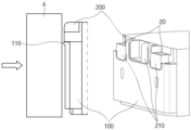
- FIG. 1 is a perspective view of a battery module according to an embodiment of the present invention.
- a battery module 1 may include a plurality of batteries.
- the plurality of batteries may be secondary batteries.
- the battery module 1 may include a frame 10.
- the frame 10 may define an outer periphery of the battery module 1 outside the plurality of batteries.
- the battery module 1 may include elements 20.
- the elements 20 may be electrically connected to the plurality of batteries.
- the elements 20 may be disposed outside the plurality of batteries to electrically connect the outside of the battery module 1 to the plurality of batteries.
- the elements 20 may include a bus bar 21 and a connector 22.
- the frame 10 may include an end plate 100.
- the end plate 100 may be disposed outside the plurality of batteries.
- the end plate 100 may be disposed on a predetermined plane (e.g., YZ plane) in a predetermined direction (e.g., X-axis direction) from the outside of the plurality of batteries to cover one side of each of the plurality of batteries.
- a predetermined plane e.g., YZ plane
- a predetermined direction e.g., X-axis direction
- the end plate 100 may include a buffer part 110.
- the end plate 100 may have a buffer part 110 provided at an edge adjacent to the elements 20 electrically connected to the plurality of batteries.
- the buffer part 110 may be disposed in a shape surrounding the elements 20.
- the buffer part 110 may be provided in a shape surrounding the elements 20 by being spaced a predetermined distance from the elements 20.
- the shape of the buffer part 110 is not particularly limited as described above and may be designed variously within a reasonable range of design changes in the above-described embodiment to protect the elements 20 from an external impact.
- the buffer part 110 may include an elastic member.
- the buffer part 110 may include the elastic member to effectively absorb and alleviate the external impact.
- it is not limited thereto, and there may not be particularly limited as long as the buffer part is a member capable of absorbing an impact.
- the buffer part 110 may protrude toward the outside.
- the buffer part 110 may protrude to a certain extent in the +X direction from the plurality of batteries.
- the frame 10 may include an insulating cover 200.
- the insulating cover 200 may be disposed between the plurality of batteries and the end plate 100.
- the plurality of batteries, the insulating cover 200, and the end plate 100 may be sequentially arranged in the +X direction.
- the insulating cover 200 may include an element cover part 210.
- the element cover part 210 may be a portion covering the elements 20 in the insulating cover 200.
- the element cover part 210 may be disposed to cover at least a direction (e.g., a vertical direction) transverse to the X-axis direction based on the arrangement position of the elements 20.
- the element cover part 210 may be provided on a YZ plane to protect the elements 20 from an interference acting in the X-axis direction.
- the buffer part 110 may be disposed along an edge of the element cover part 210.
- the buffer part 110 may protrude in the X-axis direction from a portion corresponding to the edge of the element cover part 210.
- the elements 20 may be protected from the external impact.
- FIG. 2 is an exploded perspective view of an end plate assembly according to an embodiment of the present invention.
- An opening 220 may be defined in the insulating cover 200.
- the opening 220 may be opened toward a direction other than a direction toward the end plate 10.
- the opening 220 may be opened in a direction other than the direction toward the end plate 100 (e.g., the +X direction) so that the elements 20 and the external device are electrically connected to each other.
- a portion of the insulating cover 200 may be seated on the buffer part 110. Specifically, the element cover part 210 of the insulating cover 200 may be seated on the buffer part 110 protruding outward. Thus, the sagging of the insulating cover 200 may be suppressed to improve structural stability.
- the element cover part 210 may protrude outward so as to be seated on the buffer part 110.
- the buffer part 110 may be provided discontinuously.
- the buffer part 110 may be discontinuously provided at the edge of the end plate 100 at the side of each of the elements 20. As the buffer part 10 is provided discontinuously, an effect of impact absorption may be improved even with the minimum buffer part 110.
- FIG. 3 is an enlarged cross-sectional view of the buffer part and the insulating cover according to an embodiment of the present invention
- FIG. 4 is a conceptual view illustrating impact absorption of the buffer part according to an embodiment of the present invention.
- the buffer part 110 may protrude more outward than the insulating cover 200.
- a portion of the insulating cover 200 e.g., the element cover part 210) also protrudes outward, but the buffer part 110 may protrude more in the +X direction than the insulating cover 200.
- the buffer part 110 may preferentially collide or contact the external object A to absorb an impact.
- the above-described collision or contact from the external object A may include pressurization by a cylinder or a jig.
- the collision or contact from the external object A may include an unexpected external impact.
- the buffer part 110 may have a rib shape.
- the insulating cover 200 may perform an insulating function to prevent unintended electrical connection other than electrical connection through the elements 20 from occurring.
- a portion of the insulating cover 200 may be seated on the buffer part 110 protruding outward to realize structural stability, thereby securing reliability of the insulating function.
- the buffer part 110 may support the element cover part 210 of the insulating cover 200.
- the buffer part 110 may be disposed along the edge of the end plate 100, on which the element cover part 210 is seated, to support the element cover part 210.
- the buffer part 110 may be discontinuously provided at a portion of the edge of the end plate 100 that supports the element cover part 210.
Landscapes
- Chemical & Material Sciences (AREA)
- Chemical Kinetics & Catalysis (AREA)
- Electrochemistry (AREA)
- General Chemical & Material Sciences (AREA)
- Engineering & Computer Science (AREA)
- Manufacturing & Machinery (AREA)
- Connection Of Batteries Or Terminals (AREA)
- Battery Mounting, Suspending (AREA)
Abstract
Description
- The present application claims the benefit of the priority of
Korean Patent Application Nos. 10-2022-0073816, filed on June 16, 2022 10-2023-0047795, filed on April 11, 2023 - The present invention relates to an end plate assembly and a battery module including the same.
- As the demand for solving the problem of environmental pollution caused by the abuse of petroleum resources and the demand for alternative energy sources to replace fossil energy increase, research and development on power generation based on Eco-friendly energy sources are being conducted. Particularly, researches on secondary batteries capable of being repeatedly chargeable/dischargeable are being actively conducted, and research/development on various aspects such as materials, structures, processes, and stability of secondary batteries are being conducted.
- Secondary batteries may be managed in module units. For example, a plurality of secondary batteries may be mounted in a battery module in series/parallel arrangement and managed by a battery management system. There may be various arrangement/management examples according to the type or shape of the secondary battery.
- In order to electrically connect the secondary batteries to each other, elements such as a bus bar or a connector may be exposed to the outside, and there is a need to protect the element from an external impact.
- According to the prior art, it is difficult to absorb the impact from the outside through a plate defining outer peripheries of the secondary batteries, and thus, the internal elements may be damaged.
- An object of the present invention for solving the above problem is to provide an end plate assembly capable of minimizing an external impact and improving structure stability, and a battery module including the same.
- A battery module according to an embodiment of the present invention includes a plurality of batteries, and an end plate disposed outside the plurality of batteries and provided with a buffer part at an edge adjacent to elements that are electrically connected to the plurality of batteries.
- An end plate assembly according to an embodiment of the present invention includes an insulating cover disposed outside a plurality of secondary batteries and provided with an element cover part configured to cover elements electrically connected to the plurality of batteries, and an end plate disposed outside the insulating cover and provided with a buffer part at an edge adjacent to the element cover part.
- According to the preferred embodiment of the present invention, the external impact may be mitigated to improve the elements from being damaged.
- According to the preferred embodiment of the present invention, the structural stability may be improved.
-
-
FIG. 1 is a perspective view of a battery module according to an embodiment of the present invention. -
FIG. 2 is an exploded perspective view of an end plate assembly according to an embodiment of the present invention. -
FIG. 3 is an enlarged cross-sectional view of a buffer part and an insulating cover according to an embodiment of the present invention. -
FIG. 4 is a conceptual view illustrating impact absorption of the buffer part according to an embodiment of the present invention. - Hereinafter, preferred embodiments of the present invention will be described in detail with reference to the accompanying drawings so that those of ordinary skill in the art can easily carry out the present invention. However, the present invention may be implemented in several different forms and is not limited or restricted by the following examples.
- In order to clearly explain the present invention, detailed descriptions of portions that are irrelevant to the description or related known technologies that may unnecessarily obscure the gist of the present invention have been omitted, and in the present specification, reference symbols are added to components in each drawing. In this case, the same or similar reference numerals are assigned to the same or similar elements throughout the specification.
- Also, terms or words used in this specification and claims should not be restrictively interpreted as ordinary meanings or dictionary-based meanings, but should be interpreted as meanings and concepts conforming to the scope of the present invention on the basis of the principle that an inventor can properly define the concept of a term to describe and explain his or her invention in the best ways.
-
FIG. 1 is a perspective view of a battery module according to an embodiment of the present invention. - A
battery module 1 may include a plurality of batteries. The plurality of batteries may be secondary batteries. - The
battery module 1 may include aframe 10. Theframe 10 may define an outer periphery of thebattery module 1 outside the plurality of batteries. - The
battery module 1 may includeelements 20. Theelements 20 may be electrically connected to the plurality of batteries. For example, theelements 20 may be disposed outside the plurality of batteries to electrically connect the outside of thebattery module 1 to the plurality of batteries. Theelements 20 may include abus bar 21 and aconnector 22. - The
frame 10 may include anend plate 100. - The
end plate 100 may be disposed outside the plurality of batteries. For example, referring toFIG. 1 , theend plate 100 may be disposed on a predetermined plane (e.g., YZ plane) in a predetermined direction (e.g., X-axis direction) from the outside of the plurality of batteries to cover one side of each of the plurality of batteries. - The
end plate 100 may include abuffer part 110. Theend plate 100 may have abuffer part 110 provided at an edge adjacent to theelements 20 electrically connected to the plurality of batteries. Particularly, for example, when viewed in the X-axis direction, thebuffer part 110 may be disposed in a shape surrounding theelements 20. For another example, when viewed in the X-axis direction, thebuffer part 110 may be provided in a shape surrounding theelements 20 by being spaced a predetermined distance from theelements 20. - The shape of the
buffer part 110 is not particularly limited as described above and may be designed variously within a reasonable range of design changes in the above-described embodiment to protect theelements 20 from an external impact. - The
buffer part 110 may include an elastic member. For example, thebuffer part 110 may include the elastic member to effectively absorb and alleviate the external impact. However, it is not limited thereto, and there may not be particularly limited as long as the buffer part is a member capable of absorbing an impact. - The
buffer part 110 may protrude toward the outside. For example, thebuffer part 110 may protrude to a certain extent in the +X direction from the plurality of batteries. - The
frame 10 may include aninsulating cover 200. - The
insulating cover 200 may be disposed between the plurality of batteries and theend plate 100. For example, the plurality of batteries, theinsulating cover 200, and theend plate 100 may be sequentially arranged in the +X direction. - The
insulating cover 200 may include anelement cover part 210. Theelement cover part 210 may be a portion covering theelements 20 in theinsulating cover 200. For example, theelement cover part 210 may be disposed to cover at least a direction (e.g., a vertical direction) transverse to the X-axis direction based on the arrangement position of theelements 20. In other words, theelement cover part 210 may be provided on a YZ plane to protect theelements 20 from an interference acting in the X-axis direction. - The
buffer part 110 may be disposed along an edge of theelement cover part 210. For example, thebuffer part 110 may protrude in the X-axis direction from a portion corresponding to the edge of theelement cover part 210. - As described above, as the
buffer part 110 protrudes, theelements 20 may be protected from the external impact. -
FIG. 2 is an exploded perspective view of an end plate assembly according to an embodiment of the present invention. - An opening 220 may be defined in the
insulating cover 200. For example, theopening 220 may be opened toward a direction other than a direction toward theend plate 10. In other words, theopening 220 may be opened in a direction other than the direction toward the end plate 100 (e.g., the +X direction) so that theelements 20 and the external device are electrically connected to each other. - A portion of the insulating
cover 200 may be seated on thebuffer part 110. Specifically, theelement cover part 210 of the insulatingcover 200 may be seated on thebuffer part 110 protruding outward. Thus, the sagging of the insulatingcover 200 may be suppressed to improve structural stability. - The element cover
part 210 may protrude outward so as to be seated on thebuffer part 110. - The
buffer part 110 may be provided discontinuously. For example, thebuffer part 110 may be discontinuously provided at the edge of theend plate 100 at the side of each of theelements 20. As thebuffer part 10 is provided discontinuously, an effect of impact absorption may be improved even with theminimum buffer part 110. -
FIG. 3 is an enlarged cross-sectional view of the buffer part and the insulating cover according to an embodiment of the present invention, andFIG. 4 is a conceptual view illustrating impact absorption of the buffer part according to an embodiment of the present invention. - Referring to
FIG. 3 , thebuffer part 110 may protrude more outward than the insulatingcover 200. For example, a portion of the insulating cover 200 (e.g., the element cover part 210) also protrudes outward, but thebuffer part 110 may protrude more in the +X direction than the insulatingcover 200. - As described above, since the
buffer part 110 further protrudes, when collision or contact with an external object A occurs, thebuffer part 110 may preferentially collide or contact the external object A to absorb an impact. - The above-described collision or contact from the external object A may include pressurization by a cylinder or a jig. In addition, the collision or contact from the external object A may include an unexpected external impact.
- The
buffer part 110 may have a rib shape. - Referring to
FIG. 4 , the insulatingcover 200 may perform an insulating function to prevent unintended electrical connection other than electrical connection through theelements 20 from occurring. - A portion of the insulating
cover 200 may be seated on thebuffer part 110 protruding outward to realize structural stability, thereby securing reliability of the insulating function. - The
buffer part 110 may support theelement cover part 210 of the insulatingcover 200. Thebuffer part 110 may be disposed along the edge of theend plate 100, on which theelement cover part 210 is seated, to support theelement cover part 210. - The
buffer part 110 may be discontinuously provided at a portion of the edge of theend plate 100 that supports theelement cover part 210. - When the insulating
cover 200 is supported by thebuffer part 110, relative movement between the insulatingcover 200 and theend plate 100 may be suppressed to improve the structural stability. - While the embodiments of the present invention have been described with reference to the specific embodiments, it will be apparent to those skilled in the art that various changes and modifications may be made without departing from the spirit and scope of the invention as defined in the following claims.
-
- 1:
- Battery module
- 10:
- Frame
- 20:
- Elements
- 21:
- Bus bar
- 22:
- Connector
- 100:
- Plate
- 110:
- Buffer part
- 200:
- Insulating cover
- 210:
- Element cover part
- 220:
- Opening
Claims (14)
- A battery module comprising:a plurality of batteries; andan end plate disposed outside the plurality of batteries and provided with a buffer part at an edge adjacent to elements that are electrically connected to the plurality of batteries.
- The battery module of claim 1, wherein the buffer part protrudes outward.
- The battery module of claim 1, further comprising an insulating cover disposed between the plurality of batteries and the end plate, provided with an element cover part configured to cover the elements.
- The battery module of claim 3, wherein a portion of the insulating cover is seated on the buffer part protruding outward.
- The battery module of claim 3, wherein the buffer part is disposed along an edge of the element cover part.
- The battery module of claim 3, wherein the insulating cover has an opening so that the elements and an external device are electrically connected to each other in a direction other than a direction toward the end plate.
- The battery module of claim 3, wherein the element cover part protrudes outward to be seated on the buffer part.
- The battery module of claim 3, wherein the buffer part further protrudes outward than the insulating cover.
- The battery module of claim 1, wherein the buffer part is discontinuously provided at the edge.
- The battery module of claim 1, wherein the elements comprise at least one of a bus bar and a connector.
- An end plate assembly comprising:an insulating cover disposed outside a plurality of secondary batteries and provided with an element cover part configured to cover elements electrically connected to the plurality of batteries; andan end plate disposed outside the insulating cover and provided with a buffer part at an edge adjacent to the element cover part.
- The end plate assembly of claim 11, wherein a portion of the insulating cover is seated on the buffer part protruding outward.
- The end plate assembly of claim 11, wherein the buffer part protrudes outward.
- The end plate assembly of claim 13, wherein the buffer part further protrudes outward than the insulating cover.
Applications Claiming Priority (3)
| Application Number | Priority Date | Filing Date | Title |
|---|---|---|---|
| KR20220073816 | 2022-06-16 | ||
| KR1020230047795A KR20230173013A (en) | 2022-06-16 | 2023-04-11 | End plate assembly and battery module including the same |
| PCT/KR2023/006441 WO2023243870A1 (en) | 2022-06-16 | 2023-05-11 | End plate assembly and battery module comprising same |
Publications (3)
| Publication Number | Publication Date |
|---|---|
| EP4415151A1 true EP4415151A1 (en) | 2024-08-14 |
| EP4415151A4 EP4415151A4 (en) | 2025-03-19 |
| EP4415151B1 EP4415151B1 (en) | 2025-10-15 |
Family
ID=89191495
Family Applications (1)
| Application Number | Title | Priority Date | Filing Date |
|---|---|---|---|
| EP23824096.4A Active EP4415151B1 (en) | 2022-06-16 | 2023-05-11 | End plate assembly and battery module including the same |
Country Status (5)
| Country | Link |
|---|---|
| US (1) | US20250316826A1 (en) |
| EP (1) | EP4415151B1 (en) |
| JP (1) | JP2024538303A (en) |
| ES (1) | ES3052452T3 (en) |
| WO (1) | WO2023243870A1 (en) |
Family Cites Families (14)
| Publication number | Priority date | Publication date | Assignee | Title |
|---|---|---|---|---|
| KR101005607B1 (en) * | 2006-10-30 | 2011-01-05 | 주식회사 엘지화학 | Battery module including a buffer member |
| JP2009048914A (en) * | 2007-08-21 | 2009-03-05 | Sanyo Electric Co Ltd | Battery pack |
| KR101726774B1 (en) * | 2015-02-23 | 2017-04-13 | 주식회사 엘지화학 | Modularized Assembly for Battery Pack and Battery Pack Including the Same |
| JP6596467B2 (en) * | 2017-06-28 | 2019-10-23 | 本田技研工業株式会社 | Battery module |
| US11817593B2 (en) * | 2018-03-30 | 2023-11-14 | Sanyo Electric Co., Ltd. | Power supply device and vehicle provided with power supply device |
| CN109037527B (en) * | 2018-07-25 | 2024-03-19 | 江苏正力新能电池技术有限公司 | Battery module |
| KR102684926B1 (en) * | 2018-12-20 | 2024-07-17 | 주식회사 엘지에너지솔루션 | Battery module |
| CN209896117U (en) * | 2019-01-07 | 2020-01-03 | 欣旺达电动汽车电池有限公司 | End plate and battery module |
| KR102583650B1 (en) * | 2019-07-01 | 2023-09-26 | 주식회사 엘지에너지솔루션 | Battery module and battery pack including the same |
| KR102754506B1 (en) * | 2019-09-27 | 2025-01-13 | 주식회사 엘지에너지솔루션 | Battery module and battery pack including the same |
| KR102877571B1 (en) * | 2019-11-25 | 2025-10-27 | 주식회사 엘지에너지솔루션 | Battery module and battery pack including the same |
| KR102931492B1 (en) * | 2019-11-28 | 2026-02-25 | 주식회사 엘지에너지솔루션 | Battery module and battery pack including the same |
| KR20220052183A (en) * | 2020-10-20 | 2022-04-27 | 현대자동차주식회사 | Battery module and battery pack comprising the same |
| CN112510322A (en) * | 2020-11-23 | 2021-03-16 | 上海卡耐新能源有限公司 | Battery module and battery pack |
-
2023
- 2023-05-11 JP JP2024525666A patent/JP2024538303A/en active Pending
- 2023-05-11 EP EP23824096.4A patent/EP4415151B1/en active Active
- 2023-05-11 WO PCT/KR2023/006441 patent/WO2023243870A1/en not_active Ceased
- 2023-05-11 US US18/708,075 patent/US20250316826A1/en active Pending
- 2023-05-11 ES ES23824096T patent/ES3052452T3/en active Active
Also Published As
| Publication number | Publication date |
|---|---|
| EP4415151B1 (en) | 2025-10-15 |
| ES3052452T3 (en) | 2026-01-07 |
| JP2024538303A (en) | 2024-10-18 |
| EP4415151A4 (en) | 2025-03-19 |
| US20250316826A1 (en) | 2025-10-09 |
| WO2023243870A1 (en) | 2023-12-21 |
Similar Documents
| Publication | Publication Date | Title |
|---|---|---|
| JP6176126B2 (en) | Wiring module and power storage module | |
| US10992008B2 (en) | Drawer-type battery pack | |
| JP2023527211A (en) | Battery pack cases, battery packs and vehicles | |
| JP7055487B2 (en) | Battery module including connector with shock absorbing structure | |
| KR20190011204A (en) | Battery connection module | |
| US20210098846A1 (en) | Battery module including protection cover covering flexible printed circuit board | |
| KR102877571B1 (en) | Battery module and battery pack including the same | |
| KR101532499B1 (en) | Bus bar case, electric storage device, and vehicle | |
| JP7616061B2 (en) | Power storage device | |
| EP4415151A1 (en) | End plate assembly and battery module comprising same | |
| KR20150129494A (en) | Vehicle Battery Pack having Crash Beam | |
| CN118202515A (en) | End plate assembly and battery module including the end plate assembly | |
| JP6631869B2 (en) | Power storage device | |
| JP2021068561A (en) | Power storage device | |
| KR20230173013A (en) | End plate assembly and battery module including the same | |
| WO2021131861A1 (en) | Battery wiring module | |
| JP7077932B2 (en) | Connection module | |
| KR102900632B1 (en) | Battery pack case including flange-type holding structures and battery pack comprising the same | |
| JP2014203742A (en) | Battery module | |
| CN218548865U (en) | Battery replacing connector | |
| JP2024538832A (en) | A frame including a guideline and a battery module including the frame | |
| JP7258376B2 (en) | Battery modules and battery packs containing the same | |
| CN118104048A (en) | Frame including guide rails and battery module including the frame | |
| JP2026037606A (en) | Busbar module case and busbar module | |
| JP2021068558A (en) | Power storage device |
Legal Events
| Date | Code | Title | Description |
|---|---|---|---|
| STAA | Information on the status of an ep patent application or granted ep patent |
Free format text: STATUS: THE INTERNATIONAL PUBLICATION HAS BEEN MADE |
|
| PUAI | Public reference made under article 153(3) epc to a published international application that has entered the european phase |
Free format text: ORIGINAL CODE: 0009012 |
|
| STAA | Information on the status of an ep patent application or granted ep patent |
Free format text: STATUS: REQUEST FOR EXAMINATION WAS MADE |
|
| 17P | Request for examination filed |
Effective date: 20240507 |
|
| AK | Designated contracting states |
Kind code of ref document: A1 Designated state(s): AL AT BE BG CH CY CZ DE DK EE ES FI FR GB GR HR HU IE IS IT LI LT LU LV MC ME MK MT NL NO PL PT RO RS SE SI SK SM TR |
|
| A4 | Supplementary search report drawn up and despatched |
Effective date: 20250214 |
|
| RIC1 | Information provided on ipc code assigned before grant |
Ipc: H01M 50/507 20210101ALI20250210BHEP Ipc: H01M 50/271 20210101ALI20250210BHEP Ipc: H01M 50/209 20210101ALI20250210BHEP Ipc: H01M 50/296 20210101ALI20250210BHEP Ipc: H01M 50/242 20210101ALI20250210BHEP Ipc: H01M 50/204 20210101ALI20250210BHEP Ipc: H01M 50/591 20210101ALI20250210BHEP Ipc: H01M 10/04 20060101ALI20250210BHEP Ipc: H01M 50/502 20210101ALI20250210BHEP Ipc: H01M 50/593 20210101ALI20250210BHEP Ipc: H01M 50/588 20210101ALI20250210BHEP Ipc: H01M 50/579 20210101ALI20250210BHEP Ipc: H01M 50/59 20210101AFI20250210BHEP |
|
| GRAP | Despatch of communication of intention to grant a patent |
Free format text: ORIGINAL CODE: EPIDOSNIGR1 |
|
| STAA | Information on the status of an ep patent application or granted ep patent |
Free format text: STATUS: GRANT OF PATENT IS INTENDED |
|
| GRAS | Grant fee paid |
Free format text: ORIGINAL CODE: EPIDOSNIGR3 |
|
| DAV | Request for validation of the european patent (deleted) | ||
| DAX | Request for extension of the european patent (deleted) | ||
| INTG | Intention to grant announced |
Effective date: 20250807 |
|
| GRAA | (expected) grant |
Free format text: ORIGINAL CODE: 0009210 |
|
| STAA | Information on the status of an ep patent application or granted ep patent |
Free format text: STATUS: THE PATENT HAS BEEN GRANTED |
|
| AK | Designated contracting states |
Kind code of ref document: B1 Designated state(s): AL AT BE BG CH CY CZ DE DK EE ES FI FR GB GR HR HU IE IS IT LI LT LU LV MC ME MK MT NL NO PL PT RO RS SE SI SK SM TR |
|
| REG | Reference to a national code |
Ref country code: GB Ref legal event code: FG4D Ref country code: CH Ref legal event code: F10 Free format text: ST27 STATUS EVENT CODE: U-0-0-F10-F00 (AS PROVIDED BY THE NATIONAL OFFICE) Effective date: 20251015 |
|
| P01 | Opt-out of the competence of the unified patent court (upc) registered |
Free format text: CASE NUMBER: UPC_APP_6780_4415151/2025 Effective date: 20250911 |
|
| REG | Reference to a national code |
Ref country code: IE Ref legal event code: FG4D |
|
| REG | Reference to a national code |
Ref country code: DE Ref legal event code: R096 Ref document number: 602023007620 Country of ref document: DE |
|
| REG | Reference to a national code |
Ref country code: ES Ref legal event code: FG2A Ref document number: 3052452 Country of ref document: ES Kind code of ref document: T3 Effective date: 20260107 |
|
| REG | Reference to a national code |
Ref country code: NL Ref legal event code: MP Effective date: 20251015 |
|
| REG | Reference to a national code |
Ref country code: AT Ref legal event code: MK05 Ref document number: 1847868 Country of ref document: AT Kind code of ref document: T Effective date: 20251015 |
|
| PG25 | Lapsed in a contracting state [announced via postgrant information from national office to epo] |
Ref country code: NL Free format text: LAPSE BECAUSE OF FAILURE TO SUBMIT A TRANSLATION OF THE DESCRIPTION OR TO PAY THE FEE WITHIN THE PRESCRIBED TIME-LIMIT Effective date: 20251015 |
|
| REG | Reference to a national code |
Ref country code: LT Ref legal event code: MG9D |
|
| PG25 | Lapsed in a contracting state [announced via postgrant information from national office to epo] |
Ref country code: NO Free format text: LAPSE BECAUSE OF FAILURE TO SUBMIT A TRANSLATION OF THE DESCRIPTION OR TO PAY THE FEE WITHIN THE PRESCRIBED TIME-LIMIT Effective date: 20260115 |
|
| PG25 | Lapsed in a contracting state [announced via postgrant information from national office to epo] |
Ref country code: FI Free format text: LAPSE BECAUSE OF FAILURE TO SUBMIT A TRANSLATION OF THE DESCRIPTION OR TO PAY THE FEE WITHIN THE PRESCRIBED TIME-LIMIT Effective date: 20251015 Ref country code: AT Free format text: LAPSE BECAUSE OF FAILURE TO SUBMIT A TRANSLATION OF THE DESCRIPTION OR TO PAY THE FEE WITHIN THE PRESCRIBED TIME-LIMIT Effective date: 20251015 Ref country code: HR Free format text: LAPSE BECAUSE OF FAILURE TO SUBMIT A TRANSLATION OF THE DESCRIPTION OR TO PAY THE FEE WITHIN THE PRESCRIBED TIME-LIMIT Effective date: 20251015 |
|
| PG25 | Lapsed in a contracting state [announced via postgrant information from national office to epo] |
Ref country code: RS Free format text: LAPSE BECAUSE OF FAILURE TO SUBMIT A TRANSLATION OF THE DESCRIPTION OR TO PAY THE FEE WITHIN THE PRESCRIBED TIME-LIMIT Effective date: 20260115 |
|
| PG25 | Lapsed in a contracting state [announced via postgrant information from national office to epo] |
Ref country code: IS Free format text: LAPSE BECAUSE OF FAILURE TO SUBMIT A TRANSLATION OF THE DESCRIPTION OR TO PAY THE FEE WITHIN THE PRESCRIBED TIME-LIMIT Effective date: 20260215 |
|
| PG25 | Lapsed in a contracting state [announced via postgrant information from national office to epo] |
Ref country code: PT Free format text: LAPSE BECAUSE OF FAILURE TO SUBMIT A TRANSLATION OF THE DESCRIPTION OR TO PAY THE FEE WITHIN THE PRESCRIBED TIME-LIMIT Effective date: 20260216 |
|
| PG25 | Lapsed in a contracting state [announced via postgrant information from national office to epo] |
Ref country code: PL Free format text: LAPSE BECAUSE OF FAILURE TO SUBMIT A TRANSLATION OF THE DESCRIPTION OR TO PAY THE FEE WITHIN THE PRESCRIBED TIME-LIMIT Effective date: 20251015 |
|
| PG25 | Lapsed in a contracting state [announced via postgrant information from national office to epo] |
Ref country code: LV Free format text: LAPSE BECAUSE OF FAILURE TO SUBMIT A TRANSLATION OF THE DESCRIPTION OR TO PAY THE FEE WITHIN THE PRESCRIBED TIME-LIMIT Effective date: 20251015 |