EP4415123A1 - Battery cell, method for manufacturing same, and direct liquid cooling battery module comprising same - Google Patents
Battery cell, method for manufacturing same, and direct liquid cooling battery module comprising same Download PDFInfo
- Publication number
- EP4415123A1 EP4415123A1 EP23824189.7A EP23824189A EP4415123A1 EP 4415123 A1 EP4415123 A1 EP 4415123A1 EP 23824189 A EP23824189 A EP 23824189A EP 4415123 A1 EP4415123 A1 EP 4415123A1
- Authority
- EP
- European Patent Office
- Prior art keywords
- plating layer
- plate material
- metal sheet
- battery cell
- sacrificial metal
- Prior art date
- Legal status (The legal status is an assumption and is not a legal conclusion. Google has not performed a legal analysis and makes no representation as to the accuracy of the status listed.)
- Pending
Links
Images




Classifications
-
- H—ELECTRICITY
- H01—ELECTRIC ELEMENTS
- H01M—PROCESSES OR MEANS, e.g. BATTERIES, FOR THE DIRECT CONVERSION OF CHEMICAL ENERGY INTO ELECTRICAL ENERGY
- H01M10/00—Secondary cells; Manufacture thereof
- H01M10/60—Heating or cooling; Temperature control
- H01M10/65—Means for temperature control structurally associated with the cells
- H01M10/656—Means for temperature control structurally associated with the cells characterised by the type of heat-exchange fluid
- H01M10/6567—Liquids
-
- H—ELECTRICITY
- H01—ELECTRIC ELEMENTS
- H01M—PROCESSES OR MEANS, e.g. BATTERIES, FOR THE DIRECT CONVERSION OF CHEMICAL ENERGY INTO ELECTRICAL ENERGY
- H01M10/00—Secondary cells; Manufacture thereof
- H01M10/60—Heating or cooling; Temperature control
- H01M10/61—Types of temperature control
- H01M10/613—Cooling or keeping cold
-
- H—ELECTRICITY
- H01—ELECTRIC ELEMENTS
- H01M—PROCESSES OR MEANS, e.g. BATTERIES, FOR THE DIRECT CONVERSION OF CHEMICAL ENERGY INTO ELECTRICAL ENERGY
- H01M10/00—Secondary cells; Manufacture thereof
- H01M10/60—Heating or cooling; Temperature control
- H01M10/65—Means for temperature control structurally associated with the cells
- H01M10/655—Solid structures for heat exchange or heat conduction
- H01M10/6556—Solid parts with flow channel passages or pipes for heat exchange
-
- H—ELECTRICITY
- H01—ELECTRIC ELEMENTS
- H01M—PROCESSES OR MEANS, e.g. BATTERIES, FOR THE DIRECT CONVERSION OF CHEMICAL ENERGY INTO ELECTRICAL ENERGY
- H01M50/00—Constructional details or processes of manufacture of the non-active parts of electrochemical cells other than fuel cells, e.g. hybrid cells
- H01M50/10—Primary casings; Jackets or wrappings
- H01M50/116—Primary casings; Jackets or wrappings characterised by the material
- H01M50/117—Inorganic material
- H01M50/119—Metals
-
- H—ELECTRICITY
- H01—ELECTRIC ELEMENTS
- H01M—PROCESSES OR MEANS, e.g. BATTERIES, FOR THE DIRECT CONVERSION OF CHEMICAL ENERGY INTO ELECTRICAL ENERGY
- H01M50/00—Constructional details or processes of manufacture of the non-active parts of electrochemical cells other than fuel cells, e.g. hybrid cells
- H01M50/10—Primary casings; Jackets or wrappings
- H01M50/116—Primary casings; Jackets or wrappings characterised by the material
- H01M50/121—Organic material
-
- H—ELECTRICITY
- H01—ELECTRIC ELEMENTS
- H01M—PROCESSES OR MEANS, e.g. BATTERIES, FOR THE DIRECT CONVERSION OF CHEMICAL ENERGY INTO ELECTRICAL ENERGY
- H01M50/00—Constructional details or processes of manufacture of the non-active parts of electrochemical cells other than fuel cells, e.g. hybrid cells
- H01M50/10—Primary casings; Jackets or wrappings
- H01M50/116—Primary casings; Jackets or wrappings characterised by the material
- H01M50/124—Primary casings; Jackets or wrappings characterised by the material having a layered structure
- H01M50/1245—Primary casings; Jackets or wrappings characterised by the material having a layered structure characterised by the external coating on the casing
-
- H—ELECTRICITY
- H01—ELECTRIC ELEMENTS
- H01M—PROCESSES OR MEANS, e.g. BATTERIES, FOR THE DIRECT CONVERSION OF CHEMICAL ENERGY INTO ELECTRICAL ENERGY
- H01M50/00—Constructional details or processes of manufacture of the non-active parts of electrochemical cells other than fuel cells, e.g. hybrid cells
- H01M50/10—Primary casings; Jackets or wrappings
- H01M50/14—Primary casings; Jackets or wrappings for protecting against damage caused by external factors
- H01M50/141—Primary casings; Jackets or wrappings for protecting against damage caused by external factors for protecting against humidity
-
- H—ELECTRICITY
- H01—ELECTRIC ELEMENTS
- H01M—PROCESSES OR MEANS, e.g. BATTERIES, FOR THE DIRECT CONVERSION OF CHEMICAL ENERGY INTO ELECTRICAL ENERGY
- H01M50/00—Constructional details or processes of manufacture of the non-active parts of electrochemical cells other than fuel cells, e.g. hybrid cells
- H01M50/10—Primary casings; Jackets or wrappings
- H01M50/14—Primary casings; Jackets or wrappings for protecting against damage caused by external factors
- H01M50/145—Primary casings; Jackets or wrappings for protecting against damage caused by external factors for protecting against corrosion
-
- H—ELECTRICITY
- H01—ELECTRIC ELEMENTS
- H01M—PROCESSES OR MEANS, e.g. BATTERIES, FOR THE DIRECT CONVERSION OF CHEMICAL ENERGY INTO ELECTRICAL ENERGY
- H01M50/00—Constructional details or processes of manufacture of the non-active parts of electrochemical cells other than fuel cells, e.g. hybrid cells
- H01M50/20—Mountings; Secondary casings or frames; Racks, modules or packs; Suspension devices; Shock absorbers; Transport or carrying devices; Holders
- H01M50/233—Mountings; Secondary casings or frames; Racks, modules or packs; Suspension devices; Shock absorbers; Transport or carrying devices; Holders characterised by physical properties of casings or racks, e.g. dimensions
- H01M50/24—Mountings; Secondary casings or frames; Racks, modules or packs; Suspension devices; Shock absorbers; Transport or carrying devices; Holders characterised by physical properties of casings or racks, e.g. dimensions adapted for protecting batteries from their environment, e.g. from corrosion
-
- H—ELECTRICITY
- H01—ELECTRIC ELEMENTS
- H01M—PROCESSES OR MEANS, e.g. BATTERIES, FOR THE DIRECT CONVERSION OF CHEMICAL ENERGY INTO ELECTRICAL ENERGY
- H01M50/00—Constructional details or processes of manufacture of the non-active parts of electrochemical cells other than fuel cells, e.g. hybrid cells
- H01M50/20—Mountings; Secondary casings or frames; Racks, modules or packs; Suspension devices; Shock absorbers; Transport or carrying devices; Holders
- H01M50/253—Mountings; Secondary casings or frames; Racks, modules or packs; Suspension devices; Shock absorbers; Transport or carrying devices; Holders adapted for specific cells, e.g. electrochemical cells operating at high temperature
-
- Y—GENERAL TAGGING OF NEW TECHNOLOGICAL DEVELOPMENTS; GENERAL TAGGING OF CROSS-SECTIONAL TECHNOLOGIES SPANNING OVER SEVERAL SECTIONS OF THE IPC; TECHNICAL SUBJECTS COVERED BY FORMER USPC CROSS-REFERENCE ART COLLECTIONS [XRACs] AND DIGESTS
- Y02—TECHNOLOGIES OR APPLICATIONS FOR MITIGATION OR ADAPTATION AGAINST CLIMATE CHANGE
- Y02E—REDUCTION OF GREENHOUSE GAS [GHG] EMISSIONS, RELATED TO ENERGY GENERATION, TRANSMISSION OR DISTRIBUTION
- Y02E60/00—Enabling technologies; Technologies with a potential or indirect contribution to GHG emissions mitigation
- Y02E60/10—Energy storage using batteries
Definitions
- the present invention relates to a battery cell, a manufacturing method thereof, and a direct water-cooling battery module comprising the same, and relates, in detail, to a battery cell capable of improving corrosion resistance of the battery cell by using a sacrificial metal having a higher metal ionization tendency than that of a battery cell case, a manufacturing method thereof, and a direct water-cooling battery module comprising the same.
- Batteries used in eco-friendly vehicles generate a large amount of heat because high power is required, and in order to improve battery performance and lifespan, it is very important to efficiently discharge heat generated from the battery, thereby preventing the batteries from overheating.
- a direct air-cooling method As a cooling system for dissipating heat from a battery, a direct air-cooling method, an indirect water-cooling method, or a direct water-cooling method is known.
- the direct water-cooling method is a method in which battery cells are directly immersed in cooling water, and heat from the battery cells is directly discharged into the cooling water.
- Figure 1 is a schematic configuration diagram of a conventional battery module (10).
- a direct water-cooling type battery module (10) consists of a cell frame (11) and a plurality of battery cells (12).
- the plurality of battery cells (12) is spaced apart from each other in the cell frame (11).
- the cell frame (11) is provided so that cooling water can flow.
- an exterior case accommodating internal electrodes is made of nickel-plated iron. Accordingly, when the battery cell (12) is directly impregnated with cooling water, it is vulnerable to corrosion due to the material characteristics of the exterior case. In addition, there is a problem that the exterior case is polar, and has vulnerable electrical insulation.
- insulating oil or special cooling water e.g., 3M's NOVEC
- the insulating oil has a problem of being vulnerable to fire, and the special cooling water such as 3M's NOVEC is excellent as a coolant for battery cells in that it is nonpolar and has corrosion resistance, but it is expensive, whereby there is a problem of increasing the manufacturing cost of the battery module.
- the antirust agent flows down from the exterior case of the battery cell due to surface tension, whereby there is a problem that the antirust agent is not evenly applied to the exterior case.
- the present invention is intended to provide a battery cell capable of improving corrosion resistance of a battery cell by using a sacrificial metal having a higher metal ionization tendency than that of a battery cell case, a manufacturing method thereof, and a direct water-cooling battery module comprising the same.
- a battery cell manufacturing method comprises steps of scratching, in a unit plate material having a plating layer, a partial region of the plating layer to form a scratch region on the unit plate material, bonding a sacrificial metal sheet to one side of the unit plate material to cover the scratch region, and processing the unit plate material into a cylindrical shape so that the sacrificial metal sheet is exposed to the outside.
- the scratch region may comprise a plurality of non-plated portions that a partial region of the plating layer is removed from the unit plate material and a plated portion in which the plating layer remains between two adjacent non-plated portions.
- the sacrificial metal sheet may be bonded to the unit plate material by being pressure-welded with the plated portion within the scratch region and the plating layer outside the scratch region.
- the sacrificial metal sheet may be pressure-welded to the unit plate material in a state of surface contact therewith.
- the sacrificial metal sheet may be pressure-welded to the unit plate material by a hot pressure welding method.
- the sacrificial metal sheet may be pressure-welded to the unit plate material by a gas pressure welding method.
- the sacrificial metal sheet may be pressure-welded to the unit plate material by a cold pressure welding method.
- the scratch region may be provided as the plating layer is subjected to scratch treatment by a laser.
- the scratch region may be provided as the plating layer is subjected to etching treatment.
- the sacrificial metal sheet may be formed of a metal material having a higher metal ionization tendency than that of the unit plate material.
- the sacrificial metal sheet may be formed of one or more selected from the group consisting of aluminum, magnesium, zinc, an aluminum alloy, a magnesium alloy, and a zinc alloy.
- a battery cell comprises an electrode assembly, a case accommodating the electrode assembly, a plating layer formed on an outer surface of the case, a scratch region formed by removing a partial region of the plating layer; and a sacrificial metal sheet provided to surround the scratch region and formed of a material having a higher metal ionization tendency than that of the plating layer, wherein the scratch region comprises a plurality of non-plated portions that a partial region of the plating layer is removed and a plated portion in which the plating layer remains between two adjacent non-plated portions.
- the sacrificial metal sheet may be bonded to the outer surface of the case by being pressure-welded with the plated portion within the scratch region and the plating layer outside the scratch region.
- the plating layer may be a nickel-plating layer
- the sacrificial metal sheet may be formed of one or more selected from the group consisting of aluminum, magnesium, zinc, an aluminum alloy, a magnesium alloy, and a zinc alloy.
- the battery module related to one example of the present invention comprises the plurality of battery cells, a cell frame provided so that the plurality of battery cells is disposed apart from each other, and cooling water allows to flow between the plurality of battery cells, and a cooling water supply part for supplying cooling water into the cell frame, wherein the cooling water supply part is provided to supply cooling water without insulating treatment.
- a battery cell related to at least one example of the present invention a manufacturing method thereof, and a direct water-cooling battery module comprising the same have the following effects.
- a case-type plate material can be manufactured by press-welding a sacrificial metal sheet to a plate material provided with a scratch region, and then a battery cell can be manufactured by processing the case-type plate material into a cylindrical shape and then accommodating an electrode assembly therein. Accordingly, the manufacturing process of the battery cell case can be simplified, and the product defect rate can be reduced through the simplification of the manufacturing process.
- the sacrificial metal sheet is surface-bonded to the plate material by a pressure welding method, and accordingly the bonding force between the sacrificial metal sheet and the plate material can be improved.
- the sacrificial metal sheet is provided on the outer surface of the case of the battery cell, even if the battery cell is immersed in general cooling water for a long time, corrosion of the battery cell can be prevented.
- a direct water-cooling battery cell (hereinafter, also referred to as a ⁇ battery cell') according to one example of the present invention, a manufacturing method thereof, and a direct water-cooling battery module (hereinafter, also referred to as a ⁇ battery module') comprising the same will be described in detail with reference to the drawings.
- Figure 2 schematically illustrates a configuration diagram of a direct water-cooling battery module according to one example of the present invention
- Figure 3 schematically illustrates a cross-sectional diagram of a battery cell according to one example of the present invention.
- the battery module (200) according to one example of the present invention comprises a plurality of battery cells (100), a cell frame (210) accommodating the plurality of battery cells (100), and a cooling water supply part (160).
- the battery module (200) comprises a plurality of battery cells (100), a cell frame (210) provided so that the plurality of battery cells (100) is disposed apart from each other, and cooling water (W) allows to flow between the plurality of battery cells (100), and a cooling water supply part (160) for supplying cooling water (W) into the cell frame (210).
- the cell frame (210) has a predetermined space part (211) therein, and is provided in a structure in which cooling water (W) can flow within the space part (211).
- the cooling water (W) may be supplied to the inner space part (211) of the cell frame (210), and then discharged to the outside of the cell frame (210).
- the battery module (200) may comprise a cooling water discharge part for discharging the cooling water (W) to the outside of the cell frame (210).
- the cooling water supply part (160) may comprise a cooling water storage tank and a pump.
- the cooling water supply part (160) may be provided to supply cooling water (W) that is not insulated.
- the general cooling water (W) may be cooling water generally used in vehicles.
- the battery cell (100) according to one example of the present invention comprises an electrode assembly (101), a case (110), a plating layer (111a), a scratch region (S) provided on the plating layer (111a), and a sacrificial metal sheet (113) surrounding the scratch region (S).
- the battery cell (100) may comprise a cell sheet including a polymer film and provided to surround the sacrificial metal sheet (113).
- the battery cell (100) comprises an electrode assembly (101), a case (110) accommodating the electrode assembly (101), a plating layer (111a) formed on an outer surface of the case (110), a scratch region (S) formed by removing a partial region of the plating layer (111a), and a sacrificial metal sheet (113) provided to surround the scratch region (S) and formed of a material having a higher metal ionization tendency than that of the plating layer (111a).
- the moisture (H) may be transferred to the sacrificial metal sheet (113).
- the metal ionization reaction to moisture (H) in the sacrificial metal sheet (113) is greater than the metal ionization reaction to moisture in the case (110), the corrosion resistance of the case (110) can be improved.
- the battery module (200) uses general cooling water (W) for cooling of the battery cell (100)
- the moisture (H) penetrates through the corroded portion on the surface of the battery cell (100), so that the power of the battery cell (100) is energized with the general cooling water (W), whereby there may be a problem that the battery module (200) is damaged.
- the electrode assembly (101) is accommodated in the case (110), and comprises a positive electrode, a negative electrode, and a separator disposed between the positive electrode and the negative electrode.
- the electrode and the separator may constitute an integrated electrode assembly (101).
- the electrode assembly (101) may be a jelly-roll type electrode assembly in which sheet-type positive and negative electrodes are wound in a state where a separator is interposed therebetween, a stack type electrode assembly in which pluralities of positive and negative electrodes are sequentially stacked in a state where a separator is interposed therebetween, or a stack/folding type electrode assembly in which unit cells obtained by stacking positive and negative electrodes in predetermined units in a state where a separator is interposed therebetween are sequentially wound in a state where they are positioned on a separation film.
- the case (110) serves to accommodate the electrode assembly (101), and to protect the battery cell (100) from external impacts.
- the case (110) may be cylindrical, pouch, or angular, and for example, the case (110) may be cylindrical.
- the electrode assembly (101) may be a rolled jelly-roll type electrode assembly
- the case (110) may be a cylindrical case
- the direct water-cooling battery cell (100) may be a cylindrical battery cell.
- the case (110) may be formed of a metal material, and the case (110) may be formed of one or more selected from the group consisting of steel or stainless steel.
- the surface of the case (110) may be nickel (Ni)-plated. That is, the plating layer (111a) may comprise a nickel-plating layer.
- the nickel-plating layer has little discoloration, excellent rust resistance force, and excellent corrosion resistance and wear resistance.
- the nickel-plating layer may be corroded when immersed in cooling water, and as the corrosion progresses, polarity is generated and simultaneously insulation properties are deteriorated.
- the plating layer (111a) may be a factor that hinders the movement of electrons between the sacrificial metal sheet (113) and the case (110).
- the scratch region (S) is formed on the plating layer (111a), and then the sacrificial metal sheet (113) is coupled to the scratch region (S), whereby electron movement between the sacrificial metal sheet (113) and the case (110) can be made smoothly.
- the scratch part (S) may also be formed by removing a partial region of the plating layer (111a) along the thickness direction of the plating layer (111a), and the scratch part (S) may be formed up to a partial region of the plating layer (111a) along the thickness direction of the plating layer (111a), and an outer surface of the case facing the partial region.
- the scratch region (S) comprises a plurality of non-plated portions (111c, see Figure 6 ) that a partial region of the plating layer (111a) is removed and a plated portion (111d) in which the plating layer remains between two adjacent non-plated portions (111c).
- the scratch region (S) may be provided as the plating layer (111a) is subjected to scratch treatment by a laser.
- the scratch region (S) may be provided as the plating layer (111a) is subjected to etching treatment.
- the sacrificial metal sheet (113) may be bonded to the outer surface of the case (110) by being pressure-welded with the plated portion (111d) within the scratch region (S) and the plating layer (111a) outside the scratch region (S).
- the sacrificial metal sheet (113) may be pressure-welded to the case (110) in a state of surface contact therewith.
- the sacrificial metal sheet (113) may be pressure-welded to the case by a hot pressure welding method.
- the sacrificial metal sheet (113) may be pressure-welded to the unit plate material by a gas pressure welding method.
- the sacrificial metal sheet (113) may be pressure-welded to the case (110) by a cold pressure welding method.
- the sacrificial metal sheet (113) may be formed of one or more selected from the group consisting of aluminum, magnesium, zinc, an aluminum alloy, a magnesium alloy, and a zinc alloy.
- the battery module (200) may comprise a waterproof layer (150) provided inside the cell frame (210), and provided to cover the upper end and the lower end of the case (110) of the battery cell (100), respectively.
- the waterproof layer (150) performs a function of preventing moisture from permeating into the case (110) and fixing the battery cell (100) to the cell frame (210).
- An upper waterproof layer may be provided on the upper end of the case (110), and a lower waterproof layer may be provided on the lower end of the case (110).
- the upper end side, and the lower end side of the battery cell (100) may be fixed to the inner surface of the cell frame (210) through the waterproof layer (150), respectively.
- the waterproof layer (150) may comprise a waterproof adhesive or a potting resin
- the potting resin may be any one of a silicone-based resin, a urethane-based resin, and an epoxy-based resin.
- the case (110) according to the present example may be manufactured according to any one of the first example to the second example to be described below.
- Figures 4 to 6 are diagrams for explaining a manufacturing method of a battery cell according to a first example of the present invention. Particularly, they are drawings for explaining a manufacturing method of a battery cell case.
- the battery cell manufacturing method comprises steps of scratching, in a unit plate material having a plating layer, a partial region of the plating layer to form a scratch region on the unit plate material, bonding a sacrificial metal sheet to one side of the unit plate material to cover the scratch region, and processing the unit plate material into a cylindrical shape so that the sacrificial metal sheet is exposed to the outside.
- the manufacturing method of the battery cell may comprise a step of embedding an electrode assembly in the unit plate material processed into a cylindrical shape.
- a unit plate material (P1) having a plating layer (111a) is prepared.
- the unit plate material (P1) means a metal plate material having a size that can be manufactured as the case (110).
- the unit plate material (P1) comprises a metal plate material (111b) and a plating layer (111a) provided on the metal plate material.
- the plating layer (111a) is provided by nickel-plating one side of the metal plate material (111b).
- the nickel plating has little discoloration, excellent rust resistance, and excellent corrosion resistance and wear resistance.
- the plating layer (111a) may be an element that hinders the movement of electrons between the sacrificial metal sheet (113) and the unit plate material (P1).
- a scratch region (S) is provided on one side of the unit plate material (P1).
- the scratch region (S) is a region where the plating layer (111a) is damaged on one side of the unit plate material (P1).
- the scratch region (S) is provided to be surrounded by the edge region (E) of the unit plate material (P1).
- the scratch region (S) may be formed as the plating layer (111a) of the unit plate material (P) is subjected to scratch treatment by a laser.
- the scratch region (S) may be formed as the plating layer (111a) of the plate material (P) is subjected to etching treatment.
- the etching treatment method is based on a chemical corrosion method.
- the edge region (E) is a region where the plating layer (111a) is not damaged.
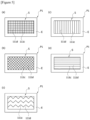
- the scratch region (S) may be formed to have a predetermined scratch pattern line.
- the scratch pattern line may be any one of a square grid pattern line ( Figure 5(a) ), an oblique grid pattern line ( Figure 5(b) ), a wavy pattern line ( Figure 5(c) ), a horizontal straight pattern line ( Figure 5(e) ), or a vertical straight pattern line ( Figure 5(c) ).
- the scratch region (S) may comprise a plurality of non-plated portions (111c) that a partial region of the plating layer (111a) is removed and a plated portion (111d) in which the plating layer remains between two adjacent non-plated portions (111c).
- the scratch region (S) is provided to be surrounded by the edge region (E) of the unit plate.
- the edge region (E) is a region where the plating layer (111a) is not removed from one side of the unit plate material.
- the sacrificial metal sheet (113) is laminated on one side of the unit plate material (P1) to cover the scratch region (S).
- the sacrificial metal sheet (113) is bonded face to face to the unit plate material (P1) by being pressure-welded to the edge region (E) and the plated portion (111d) in the scratch region (S).
- the sacrificial metal sheet (113) may be a metal sheet having a larger area than the scratch region (S).
- the sacrificial metal sheet (113) may be a metal sheet having a thickness thinner than the thickness of the unit plate material (P1).
- the sacrificial metal sheet (113) has a metal material having a higher metal ionization tendency than that of the unit plate material (P1).
- the sacrificial metal sheet (113) may be formed of one or more selected from the group consisting of aluminum, magnesium, zinc, an aluminum alloy, a magnesium alloy, and a zinc alloy.
- the sacrificial metal sheet (113) is bonded to the unit plate material (P1) by a pressure welding method.
- a pressure welding method any one of a hot pressure welding method, a cold pressure welding method, and a gas pressure welding method may be used.
- the hot pressure welding method is a method that as a welding member applies pressure and heat to the sacrificial metal sheet (113), the sacrificial metal sheet (113) is pressure-welded to the unit plate material (P1).
- the cold pressure welding method is a method that as a welding member pressurizes the sacrificial metal sheet (113) at room temperature, the sacrificial metal sheet (113) is pressure-welded to the unit plate material (P1) while being plastically deformed.
- the gas pressure welding method is a method that pressure welding is performed by heating a welding member with a gas flame to raise the temperature to a recrystallization temperature or higher, and applying a pressure in an axial direction thereto.
- the sacrificial metal sheet (113) may be pressure-welded to the unit plate material (P1) at the portions in contact with the plating layer, the bonding points of the unit plate material (P1) may be evenly distributed over the entire area of the sacrificial metal sheet, and the bonding force of the sacrificial metal sheet (113) to the unit plate material (P1) may be improved.
- the case plate material (110a) is processed into a cylindrical shape so that the sacrificial metal sheet (113) is exposed to the outside. Accordingly, the case (110) of the battery cell (100) provided with the sacrificial metal sheet (113) on the outer surface is manufactured.
- the sacrificial metal sheet (113) may be provided on the outer surface of the case (110) in a band shape along the circumference of the case (110).
- the sacrificial metal sheet (113) is bonded face to face to the unit plate material (P1) by a pressure welding method, it is possible to improve the bonding force between the sacrificial metal sheet (113) and the unit plate material (P1).
- the scratch region (S) through the scratch region (S), it is possible to solve the obstacle of electron movement due to the plating layer (111a), which has been pointed out as the problem above.
- smooth movement of electrons between the sacrificial metal sheet (113) and the unit plate material (P1) can be promoted, and accordingly the sacrificial metal sheet (113) can be electrically and stably connected to the unit plate material (P1).
- Figures 7 to 10 are diagrams for explaining a manufacturing method of a battery cell according to a second example of the present invention, which are particularly diagrams for explaining a manufacturing method of a battery cell case.
- Figure 8 is a cross-sectional diagram taken along line a-a in Figure 7
- Figure 9 is a cross-sectional diagram taken along line b-b in Figure 7
- Figure 10 is a cross-sectional diagram taken along line c-c in Figure 7 .
- the battery cell manufacturing method comprises, in respective unit regions (A1 to A4) of a plate material (P) having a plurality of unit regions on the same plane, a first step in which a plurality of scratch regions (S) is provided by scratching a plating layer (111a) of the plate material (P), a second step in which a sacrificial metal sheet (113) is laminated and bonded to one side of the plate material (P) to cover the scratch regions (S), a third step in which the plate material (P) is cut for each unit region (A1 to A4), thereby being manufactured into a plurality of case-type plate materials (110a), and a fourth step in which the case plate material (110a) is processed into a cylindrical shape so that the sacrificial metal sheet (113) is exposed to the outside.
- a plate material (P) capable of being partitioned into a plurality of unit regions on the same plane is prepared.
- the plate material (P) is provided with a plating layer (111a) on one side.
- Each unit region has a size that can be manufactured as the case (110).
- the plurality of unit regions will be referred to as a first unit region (A1) to a fourth unit region (A4).
- the plate material (P) has been partitioned into four unit regions, but this is merely an example, and the number of unit regions may be changed according to the size of the plate material (P).
- the scratch region (S) is a region provided as the plating layer (111a) of the plate material (P) is subjected to scratch treatment.
- a laser method or a chemical method may be used as in the above-described first example.
- the scratch region (S) is provided for each unit region (A1 to A4).
- the scratch regions (S) of the respective unit regions (A1 to A4) will be referred to as a first scratch region (S1) to a fourth scratch region (S4).
- the first scratch region (S1) is a region where the plating layer (11 1a) is damaged in the first unit region (A1)
- the second scratch region (S2) is a region where the plating layer (111a) is damaged in the second unit region (A2).
- the third scratch region (S3) is a region where the plating layer (111a) is damaged in the third unit region (A3)
- the fourth scratch region (S4) is a region where the plating layer (111a) is damaged in the fourth unit region (A4).
- the first scratch region (S1) to the fourth scratch region (S4) are provided on the same plane of the plate material (P) and are disposed apart from each other.
- each of the sacrificial metal sheets (113) is pressure-welded in each unit region (A1 to A4), whereby the sacrificial metal sheet (113) is bonded on one side of the plate material (P).
- the sacrificial metal sheet (113) is laminated on one side of the plate material (P) to cover the scratch region (S).
- the sacrificial metal sheet (113) has a metal material having a higher metal ionization tendency than that of the plate material (P).
- the sacrificial metal sheet (113) may be formed of one or more selected from the group consisting of aluminum, magnesium, zinc, an aluminum alloy, a magnesium alloy, and a zinc alloy.
- the sacrificial metal sheet (113) is bonded to the plate material (P) by a pressure welding method.
- a pressure welding method any one of a hot pressure welding method, a cold pressure welding method, and a gas pressure welding method may be used.
- the hot pressure welding method is a method that as a welding member applies pressure and heat to the sacrificial metal sheet (113), the sacrificial metal sheet (113) is pressure-welded to the plate material (P).
- the cold pressure welding method is a method that as a welding member pressurizes the sacrificial metal sheet (113) at room temperature, the sacrificial metal sheet (113) is pressure-welded to the plate material (P) while being plastically deformed.
- the gas pressure welding method is a method that pressure welding is performed by heating a welding member with a gas flame to raise the temperature to a recrystallization temperature or higher, and applying a pressure in an axial direction thereto.
- the plate material (P) is cut for each unit region along a cutting line (L in Figure 7 ).
- the plate material (P) cut for each unit region (A1 to A4) is referred to as a case plate material (110a).
- the case plate material (110a) is processed into a cylindrical shape so that the sacrificial metal sheet (113) is exposed to the outside. Accordingly, the case (110) provided with the sacrificial metal sheet (113) on the outer surface is manufactured.
- the corrosion resistance of the battery cell can be improved by using a sacrificial metal having a higher metal ionization tendency than that of the case of the battery cell.
Landscapes
- Chemical & Material Sciences (AREA)
- Chemical Kinetics & Catalysis (AREA)
- Electrochemistry (AREA)
- General Chemical & Material Sciences (AREA)
- Engineering & Computer Science (AREA)
- Manufacturing & Machinery (AREA)
- Inorganic Chemistry (AREA)
- Sealing Battery Cases Or Jackets (AREA)
- Battery Mounting, Suspending (AREA)
Abstract
Description
- The present invention relates to a battery cell, a manufacturing method thereof, and a direct water-cooling battery module comprising the same, and relates, in detail, to a battery cell capable of improving corrosion resistance of the battery cell by using a sacrificial metal having a higher metal ionization tendency than that of a battery cell case, a manufacturing method thereof, and a direct water-cooling battery module comprising the same.
- This application claims the benefit of priority based on
Korean Patent Application No. 10-2022-0072013 dated June 14, 2022 - Batteries used in eco-friendly vehicles generate a large amount of heat because high power is required, and in order to improve battery performance and lifespan, it is very important to efficiently discharge heat generated from the battery, thereby preventing the batteries from overheating.
- Conventionally, as a cooling system for dissipating heat from a battery, a direct air-cooling method, an indirect water-cooling method, or a direct water-cooling method is known.
- The direct water-cooling method is a method in which battery cells are directly immersed in cooling water, and heat from the battery cells is directly discharged into the cooling water.
-
Figure 1 is a schematic configuration diagram of a conventional battery module (10). - Referring to
Figure 1 , a direct water-cooling type battery module (10) consists of a cell frame (11) and a plurality of battery cells (12). The plurality of battery cells (12) is spaced apart from each other in the cell frame (11). The cell frame (11) is provided so that cooling water can flow. - Generally, in the battery cell (12), an exterior case accommodating internal electrodes is made of nickel-plated iron. Accordingly, when the battery cell (12) is directly impregnated with cooling water, it is vulnerable to corrosion due to the material characteristics of the exterior case. In addition, there is a problem that the exterior case is polar, and has vulnerable electrical insulation.
- In order to prevent corrosion of the battery cell (12) in the battery module (10) of the conventional direct water-cooling method, insulating oil or special cooling water (M) (e.g., 3M's NOVEC) is used.
- However, the insulating oil has a problem of being vulnerable to fire, and the special cooling water such as 3M's NOVEC is excellent as a coolant for battery cells in that it is nonpolar and has corrosion resistance, but it is expensive, whereby there is a problem of increasing the manufacturing cost of the battery module.
- Also, when an antirust liquid is applied to the exterior case of the battery cell (12) in order to prevent corrosion of the battery cell (12) as in the conventional art, a post-treatment process of covering the exterior case of the battery cell (12) using a non-woven fabric is required to maintain the antirust liquid.
- In addition, even if the antirust liquid is applied to the exterior case of the battery cell (12), the antirust agent flows down from the exterior case of the battery cell due to surface tension, whereby there is a problem that the antirust agent is not evenly applied to the exterior case.
- The present invention is intended to provide a battery cell capable of improving corrosion resistance of a battery cell by using a sacrificial metal having a higher metal ionization tendency than that of a battery cell case, a manufacturing method thereof, and a direct water-cooling battery module comprising the same.
- A battery cell manufacturing method according to one example of the present invention comprises steps of scratching, in a unit plate material having a plating layer, a partial region of the plating layer to form a scratch region on the unit plate material, bonding a sacrificial metal sheet to one side of the unit plate material to cover the scratch region, and processing the unit plate material into a cylindrical shape so that the sacrificial metal sheet is exposed to the outside.
- Also, the scratch region may comprise a plurality of non-plated portions that a partial region of the plating layer is removed from the unit plate material and a plated portion in which the plating layer remains between two adjacent non-plated portions.
- In addition, the sacrificial metal sheet may be bonded to the unit plate material by being pressure-welded with the plated portion within the scratch region and the plating layer outside the scratch region.
- Furthermore, the sacrificial metal sheet may be pressure-welded to the unit plate material in a state of surface contact therewith.
- Also, the sacrificial metal sheet may be pressure-welded to the unit plate material by a hot pressure welding method.
- In addition, the sacrificial metal sheet may be pressure-welded to the unit plate material by a gas pressure welding method.
- Furthermore, the sacrificial metal sheet may be pressure-welded to the unit plate material by a cold pressure welding method.
- Also, the scratch region may be provided as the plating layer is subjected to scratch treatment by a laser.
- In addition, the scratch region may be provided as the plating layer is subjected to etching treatment.
- Furthermore, the sacrificial metal sheet may be formed of a metal material having a higher metal ionization tendency than that of the unit plate material.
- Also, the sacrificial metal sheet may be formed of one or more selected from the group consisting of aluminum, magnesium, zinc, an aluminum alloy, a magnesium alloy, and a zinc alloy.
- In addition, a battery cell according to one example of the present invention comprises an electrode assembly, a case accommodating the electrode assembly, a plating layer formed on an outer surface of the case, a scratch region formed by removing a partial region of the plating layer; and a sacrificial metal sheet provided to surround the scratch region and formed of a material having a higher metal ionization tendency than that of the plating layer, wherein the scratch region comprises a plurality of non-plated portions that a partial region of the plating layer is removed and a plated portion in which the plating layer remains between two adjacent non-plated portions.
- Furthermore, the sacrificial metal sheet may be bonded to the outer surface of the case by being pressure-welded with the plated portion within the scratch region and the plating layer outside the scratch region.
- Also, the plating layer may be a nickel-plating layer, and the sacrificial metal sheet may be formed of one or more selected from the group consisting of aluminum, magnesium, zinc, an aluminum alloy, a magnesium alloy, and a zinc alloy.
- In addition, the battery module related to one example of the present invention comprises the plurality of battery cells, a cell frame provided so that the plurality of battery cells is disposed apart from each other, and cooling water allows to flow between the plurality of battery cells, and a cooling water supply part for supplying cooling water into the cell frame, wherein the cooling water supply part is provided to supply cooling water without insulating treatment.
- As described above, a battery cell related to at least one example of the present invention, a manufacturing method thereof, and a direct water-cooling battery module comprising the same have the following effects.
- A case-type plate material can be manufactured by press-welding a sacrificial metal sheet to a plate material provided with a scratch region, and then a battery cell can be manufactured by processing the case-type plate material into a cylindrical shape and then accommodating an electrode assembly therein. Accordingly, the manufacturing process of the battery cell case can be simplified, and the product defect rate can be reduced through the simplification of the manufacturing process.
- Also, it is possible to smoothly move electrons between the case and the sacrificial metal sheet through the scratch region provided in the plating layer on the case, and accordingly, the stability of the electrical connection between the sacrificial metal sheet and the case can be promoted.
- In addition, in manufacturing the case of the battery cell, the sacrificial metal sheet is surface-bonded to the plate material by a pressure welding method, and accordingly the bonding force between the sacrificial metal sheet and the plate material can be improved.
- Furthermore, as the sacrificial metal sheet is provided on the outer surface of the case of the battery cell, even if the battery cell is immersed in general cooling water for a long time, corrosion of the battery cell can be prevented.
-
-
Figure 1 is a schematic configuration diagram of a conventional battery module. -
Figure 2 schematically illustrates a configuration diagram of a direct water-cooling battery module according to one example of the present invention. -
Figure 3 schematically illustrates a cross-sectional diagram of a battery cell according to one example of the present invention. -
Figures 4 to 6 are diagrams for explaining a manufacturing method of a battery cell according to a first example of the present invention. -
Figures 7 to 10 are diagrams for explaining a manufacturing process of a case in a manufacturing method of a battery cell according to a second example of the present invention. - Hereinafter, a direct water-cooling battery cell (hereinafter, also referred to as a `battery cell') according to one example of the present invention, a manufacturing method thereof, and a direct water-cooling battery module (hereinafter, also referred to as a `battery module') comprising the same will be described in detail with reference to the drawings.
- In addition, regardless of the reference numerals, the same or corresponding components are given by the same or similar reference numerals, duplicate descriptions thereof will be omitted, and for convenience of explanation, the size and shape of each component member as shown can be exaggerated or reduced.
-
Figure 2 schematically illustrates a configuration diagram of a direct water-cooling battery module according to one example of the present invention, andFigure 3 schematically illustrates a cross-sectional diagram of a battery cell according to one example of the present invention. - Referring to
Figure 2 , the battery module (200) according to one example of the present invention comprises a plurality of battery cells (100), a cell frame (210) accommodating the plurality of battery cells (100), and a cooling water supply part (160). - Specifically, the battery module (200) comprises a plurality of battery cells (100), a cell frame (210) provided so that the plurality of battery cells (100) is disposed apart from each other, and cooling water (W) allows to flow between the plurality of battery cells (100), and a cooling water supply part (160) for supplying cooling water (W) into the cell frame (210).
- Referring to
Figure 2 , the cell frame (210) has a predetermined space part (211) therein, and is provided in a structure in which cooling water (W) can flow within the space part (211). The cooling water (W) may be supplied to the inner space part (211) of the cell frame (210), and then discharged to the outside of the cell frame (210). To this end, the battery module (200) may comprise a cooling water discharge part for discharging the cooling water (W) to the outside of the cell frame (210). In addition, the cooling water supply part (160) may comprise a cooling water storage tank and a pump. In addition, the cooling water supply part (160) may be provided to supply cooling water (W) that is not insulated. The general cooling water (W) may be cooling water generally used in vehicles. - Referring to
Figure 3 , the battery cell (100) according to one example of the present invention comprises an electrode assembly (101), a case (110), a plating layer (111a), a scratch region (S) provided on the plating layer (111a), and a sacrificial metal sheet (113) surrounding the scratch region (S). - In addition, the battery cell (100) may comprise a cell sheet including a polymer film and provided to surround the sacrificial metal sheet (113).
- The battery cell (100) comprises an electrode assembly (101), a case (110) accommodating the electrode assembly (101), a plating layer (111a) formed on an outer surface of the case (110), a scratch region (S) formed by removing a partial region of the plating layer (111a), and a sacrificial metal sheet (113) provided to surround the scratch region (S) and formed of a material having a higher metal ionization tendency than that of the plating layer (111a).
- Referring to
Figure 2 , when the direct water-cooling battery cell (100) is immersed in the cooling water (W), the moisture (H) may be transferred to the sacrificial metal sheet (113). At this time, since the metal ionization reaction to moisture (H) in the sacrificial metal sheet (113) is greater than the metal ionization reaction to moisture in the case (110), the corrosion resistance of the case (110) can be improved. - Referring to
Figure 2 , when the battery module (200) uses general cooling water (W) for cooling of the battery cell (100), the moisture (H) penetrates through the corroded portion on the surface of the battery cell (100), so that the power of the battery cell (100) is energized with the general cooling water (W), whereby there may be a problem that the battery module (200) is damaged. - Referring to
Figure 2 , when the direct water-cooling battery cell (100) is immersed in the cooling water (W), the moisture (H) of the cooling water (W) is subjected to ionization reaction with the sacrificial metal sheet (113) due to the difference in metal ionization reaction between the case (110) and the sacrificial metal sheet (113), and as a result, the metal ionization reaction of the case (110) is suppressed, whereby the direct water-cooling battery cell (100) can prevent corrosion of the case (110). - The electrode assembly (101) is accommodated in the case (110), and comprises a positive electrode, a negative electrode, and a separator disposed between the positive electrode and the negative electrode. The electrode and the separator may constitute an integrated electrode assembly (101). For example, the electrode assembly (101) may be a jelly-roll type electrode assembly in which sheet-type positive and negative electrodes are wound in a state where a separator is interposed therebetween, a stack type electrode assembly in which pluralities of positive and negative electrodes are sequentially stacked in a state where a separator is interposed therebetween, or a stack/folding type electrode assembly in which unit cells obtained by stacking positive and negative electrodes in predetermined units in a state where a separator is interposed therebetween are sequentially wound in a state where they are positioned on a separation film.
- In addition, the case (110) serves to accommodate the electrode assembly (101), and to protect the battery cell (100) from external impacts. The case (110) may be cylindrical, pouch, or angular, and for example, the case (110) may be cylindrical. In particular, the electrode assembly (101) may be a rolled jelly-roll type electrode assembly, the case (110) may be a cylindrical case, and the direct water-cooling battery cell (100) may be a cylindrical battery cell.
- Also, the case (110) may be formed of a metal material, and the case (110) may be formed of one or more selected from the group consisting of steel or stainless steel.
- In addition, the surface of the case (110) may be nickel (Ni)-plated. That is, the plating layer (111a) may comprise a nickel-plating layer.
- Meanwhile, the nickel-plating layer has little discoloration, excellent rust resistance force, and excellent corrosion resistance and wear resistance. However, due to material characteristics, the nickel-plating layer may be corroded when immersed in cooling water, and as the corrosion progresses, polarity is generated and simultaneously insulation properties are deteriorated.
- Meanwhile, when the sacrificial metal sheet (113) is provided on the plating layer (111a), the plating layer (111a) may be a factor that hinders the movement of electrons between the sacrificial metal sheet (113) and the case (110).
- The scratch region (S) is formed on the plating layer (111a), and then the sacrificial metal sheet (113) is coupled to the scratch region (S), whereby electron movement between the sacrificial metal sheet (113) and the case (110) can be made smoothly.
- Also, the scratch part (S) may also be formed by removing a partial region of the plating layer (111a) along the thickness direction of the plating layer (111a), and the scratch part (S) may be formed up to a partial region of the plating layer (111a) along the thickness direction of the plating layer (111a), and an outer surface of the case facing the partial region.
- In addition, the scratch region (S) comprises a plurality of non-plated portions (111c, see
Figure 6 ) that a partial region of the plating layer (111a) is removed and a plated portion (111d) in which the plating layer remains between two adjacent non-plated portions (111c). - Furthermore, the scratch region (S) may be provided as the plating layer (111a) is subjected to scratch treatment by a laser.
- Also, the scratch region (S) may be provided as the plating layer (111a) is subjected to etching treatment.
- In addition, the sacrificial metal sheet (113) may be bonded to the outer surface of the case (110) by being pressure-welded with the plated portion (111d) within the scratch region (S) and the plating layer (111a) outside the scratch region (S).
- Furthermore, the sacrificial metal sheet (113) may be pressure-welded to the case (110) in a state of surface contact therewith.
- As one example, the sacrificial metal sheet (113) may be pressure-welded to the case by a hot pressure welding method. Alternatively, the sacrificial metal sheet (113) may be pressure-welded to the unit plate material by a gas pressure welding method. Alternatively, the sacrificial metal sheet (113) may be pressure-welded to the case (110) by a cold pressure welding method.
- The sacrificial metal sheet (113) may be formed of one or more selected from the group consisting of aluminum, magnesium, zinc, an aluminum alloy, a magnesium alloy, and a zinc alloy.
- Referring to
Figure 2 , the battery module (200) may comprise a waterproof layer (150) provided inside the cell frame (210), and provided to cover the upper end and the lower end of the case (110) of the battery cell (100), respectively. - The waterproof layer (150) performs a function of preventing moisture from permeating into the case (110) and fixing the battery cell (100) to the cell frame (210).
- An upper waterproof layer may be provided on the upper end of the case (110), and a lower waterproof layer may be provided on the lower end of the case (110). In addition, the upper end side, and the lower end side of the battery cell (100) may be fixed to the inner surface of the cell frame (210) through the waterproof layer (150), respectively.
- In addition, the waterproof layer (150) may comprise a waterproof adhesive or a potting resin, and the potting resin may be any one of a silicone-based resin, a urethane-based resin, and an epoxy-based resin.
- The case (110) according to the present example may be manufactured according to any one of the first example to the second example to be described below.
-
Figures 4 to 6 are diagrams for explaining a manufacturing method of a battery cell according to a first example of the present invention. Particularly, they are drawings for explaining a manufacturing method of a battery cell case. - The battery cell manufacturing method according to the first example comprises steps of scratching, in a unit plate material having a plating layer, a partial region of the plating layer to form a scratch region on the unit plate material, bonding a sacrificial metal sheet to one side of the unit plate material to cover the scratch region, and processing the unit plate material into a cylindrical shape so that the sacrificial metal sheet is exposed to the outside.
- In addition, the manufacturing method of the battery cell may comprise a step of embedding an electrode assembly in the unit plate material processed into a cylindrical shape.
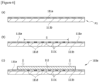
- First, referring to
Figures 4(a) and6(a) , a unit plate material (P1) having a plating layer (111a) is prepared. Here, the unit plate material (P1) means a metal plate material having a size that can be manufactured as the case (110). The unit plate material (P1) comprises a metal plate material (111b) and a plating layer (111a) provided on the metal plate material. The plating layer (111a) is provided by nickel-plating one side of the metal plate material (111b). - The nickel plating has little discoloration, excellent rust resistance, and excellent corrosion resistance and wear resistance. However, the plating layer (111a) may be an element that hinders the movement of electrons between the sacrificial metal sheet (113) and the unit plate material (P1).
- To solve this problem, in the unit plate material (P1) having the plating layer (111a), a partial region of the plating layer (111a) is scratched. Accordingly, a scratch region (S) is provided on one side of the unit plate material (P1). Referring to
Figure 6(b) , the scratch region (S) is a region where the plating layer (111a) is damaged on one side of the unit plate material (P1). - Referring to
Figure 4(b) , the scratch region (S) is provided to be surrounded by the edge region (E) of the unit plate material (P1). The scratch region (S) may be formed as the plating layer (111a) of the unit plate material (P) is subjected to scratch treatment by a laser. Alternatively, the scratch region (S) may be formed as the plating layer (111a) of the plate material (P) is subjected to etching treatment. The etching treatment method is based on a chemical corrosion method. The edge region (E) is a region where the plating layer (111a) is not damaged. - Referring to
Figure 5 , the scratch region (S) may be formed to have a predetermined scratch pattern line. For example, the scratch pattern line may be any one of a square grid pattern line (Figure 5(a) ), an oblique grid pattern line (Figure 5(b) ), a wavy pattern line (Figure 5(c) ), a horizontal straight pattern line (Figure 5(e) ), or a vertical straight pattern line (Figure 5(c) ). - According to such a scratch pattern, the scratch region (S) may comprise a plurality of non-plated portions (111c) that a partial region of the plating layer (111a) is removed and a plated portion (111d) in which the plating layer remains between two adjacent non-plated portions (111c).
- The scratch region (S) is provided to be surrounded by the edge region (E) of the unit plate. The edge region (E) is a region where the plating layer (111a) is not removed from one side of the unit plate material.
- Referring to
Figures 4(c) and6(c) , the sacrificial metal sheet (113) is laminated on one side of the unit plate material (P1) to cover the scratch region (S). The sacrificial metal sheet (113) is bonded face to face to the unit plate material (P1) by being pressure-welded to the edge region (E) and the plated portion (111d) in the scratch region (S). - The sacrificial metal sheet (113) may be a metal sheet having a larger area than the scratch region (S). In addition, the sacrificial metal sheet (113) may be a metal sheet having a thickness thinner than the thickness of the unit plate material (P1).
- The sacrificial metal sheet (113) has a metal material having a higher metal ionization tendency than that of the unit plate material (P1). For example, the sacrificial metal sheet (113) may be formed of one or more selected from the group consisting of aluminum, magnesium, zinc, an aluminum alloy, a magnesium alloy, and a zinc alloy.
- The sacrificial metal sheet (113) is bonded to the unit plate material (P1) by a pressure welding method. As the pressure welding method, any one of a hot pressure welding method, a cold pressure welding method, and a gas pressure welding method may be used.
- As one example, the hot pressure welding method is a method that as a welding member applies pressure and heat to the sacrificial metal sheet (113), the sacrificial metal sheet (113) is pressure-welded to the unit plate material (P1).
- As another example, the cold pressure welding method is a method that as a welding member pressurizes the sacrificial metal sheet (113) at room temperature, the sacrificial metal sheet (113) is pressure-welded to the unit plate material (P1) while being plastically deformed.
- As another example, the gas pressure welding method is a method that pressure welding is performed by heating a welding member with a gas flame to raise the temperature to a recrystallization temperature or higher, and applying a pressure in an axial direction thereto.
- In the scratch region (S) and the edge region (E), the sacrificial metal sheet (113) may be pressure-welded to the unit plate material (P1) at the portions in contact with the plating layer, the bonding points of the unit plate material (P1) may be evenly distributed over the entire area of the sacrificial metal sheet, and the bonding force of the sacrificial metal sheet (113) to the unit plate material (P1) may be improved.
- By bonding the sacrificial metal sheet (113) to one side of the unit plate material (P1), it is possible to manufacture a case plate material (Figure 3(c), 110a). Referring to
Figure 4(d) , the case plate material (110a) is processed into a cylindrical shape so that the sacrificial metal sheet (113) is exposed to the outside. Accordingly, the case (110) of the battery cell (100) provided with the sacrificial metal sheet (113) on the outer surface is manufactured. As one example, the sacrificial metal sheet (113) may be provided on the outer surface of the case (110) in a band shape along the circumference of the case (110). - In the present example, as the sacrificial metal sheet (113) is bonded face to face to the unit plate material (P1) by a pressure welding method, it is possible to improve the bonding force between the sacrificial metal sheet (113) and the unit plate material (P1).
- In the present invention, through the scratch region (S), it is possible to solve the obstacle of electron movement due to the plating layer (111a), which has been pointed out as the problem above. In addition, smooth movement of electrons between the sacrificial metal sheet (113) and the unit plate material (P1) can be promoted, and accordingly the sacrificial metal sheet (113) can be electrically and stably connected to the unit plate material (P1).
-
Figures 7 to 10 are diagrams for explaining a manufacturing method of a battery cell according to a second example of the present invention, which are particularly diagrams for explaining a manufacturing method of a battery cell case.Figure 8 is a cross-sectional diagram taken along line a-a inFigure 7 ,Figure 9 is a cross-sectional diagram taken along line b-b inFigure 7 , andFigure 10 is a cross-sectional diagram taken along line c-c inFigure 7 . - The battery cell manufacturing method according to the second example comprises, in respective unit regions (A1 to A4) of a plate material (P) having a plurality of unit regions on the same plane, a first step in which a plurality of scratch regions (S) is provided by scratching a plating layer (111a) of the plate material (P), a second step in which a sacrificial metal sheet (113) is laminated and bonded to one side of the plate material (P) to cover the scratch regions (S), a third step in which the plate material (P) is cut for each unit region (A1 to A4), thereby being manufactured into a plurality of case-type plate materials (110a), and a fourth step in which the case plate material (110a) is processed into a cylindrical shape so that the sacrificial metal sheet (113) is exposed to the outside.
- Referring to
Figure 7(a) , a plate material (P) capable of being partitioned into a plurality of unit regions on the same plane is prepared. The plate material (P) is provided with a plating layer (111a) on one side. - Each unit region has a size that can be manufactured as the case (110). In the present example, for convenience of description, the plurality of unit regions will be referred to as a first unit region (A1) to a fourth unit region (A4).
- In the present example, for convenience of description, the plate material (P) has been partitioned into four unit regions, but this is merely an example, and the number of unit regions may be changed according to the size of the plate material (P).
- Referring to
Figures 7(b) and 8 , a plurality of scratch regions (S) is provided on one side of the plate material (P). The scratch region (S) is a region provided as the plating layer (111a) of the plate material (P) is subjected to scratch treatment. As the scratch method of the plating layer (111a), a laser method or a chemical method may be used as in the above-described first example. - In the second example, the scratch region (S) is provided for each unit region (A1 to A4). The scratch regions (S) of the respective unit regions (A1 to A4) will be referred to as a first scratch region (S1) to a fourth scratch region (S4).
- Here, the first scratch region (S1) is a region where the plating layer (11 1a) is damaged in the first unit region (A1), and the second scratch region (S2) is a region where the plating layer (111a) is damaged in the second unit region (A2).
- In addition, the third scratch region (S3) is a region where the plating layer (111a) is damaged in the third unit region (A3), and the fourth scratch region (S4) is a region where the plating layer (111a) is damaged in the fourth unit region (A4).
- The first scratch region (S1) to the fourth scratch region (S4) are provided on the same plane of the plate material (P) and are disposed apart from each other.
- Referring to
Figures 7(c) and 7(d) , each of the sacrificial metal sheets (113) is pressure-welded in each unit region (A1 to A4), whereby the sacrificial metal sheet (113) is bonded on one side of the plate material (P). - Referring to
Figures 9 and 10 , the sacrificial metal sheet (113) is laminated on one side of the plate material (P) to cover the scratch region (S). - As described above, the sacrificial metal sheet (113) has a metal material having a higher metal ionization tendency than that of the plate material (P). For example, the sacrificial metal sheet (113) may be formed of one or more selected from the group consisting of aluminum, magnesium, zinc, an aluminum alloy, a magnesium alloy, and a zinc alloy.
- The sacrificial metal sheet (113) is bonded to the plate material (P) by a pressure welding method. As the pressure welding method, any one of a hot pressure welding method, a cold pressure welding method, and a gas pressure welding method may be used.
- As one example, the hot pressure welding method is a method that as a welding member applies pressure and heat to the sacrificial metal sheet (113), the sacrificial metal sheet (113) is pressure-welded to the plate material (P). As another example, the cold pressure welding method is a method that as a welding member pressurizes the sacrificial metal sheet (113) at room temperature, the sacrificial metal sheet (113) is pressure-welded to the plate material (P) while being plastically deformed. As another example, the gas pressure welding method is a method that pressure welding is performed by heating a welding member with a gas flame to raise the temperature to a recrystallization temperature or higher, and applying a pressure in an axial direction thereto.
- When the sacrificial metal sheet (113) is bonded to one side of the plate material (P) through the above-described processes, the plate material (P) is cut for each unit region along a cutting line (L in
Figure 7 ). In the present example, the plate material (P) cut for each unit region (A1 to A4) is referred to as a case plate material (110a). - Referring to
Figure 7(f) , the case plate material (110a) is processed into a cylindrical shape so that the sacrificial metal sheet (113) is exposed to the outside. Accordingly, the case (110) provided with the sacrificial metal sheet (113) on the outer surface is manufactured. - One example of the present invention as described above have been disclosed for illustrative purposes, and those skilled in the art having ordinary knowledge of the present invention will be able to make various modifications, changes, and additions within the spirit and scope of the present invention, and such modifications, changes, and additions should be regarded as falling within the scope of the following claims.
- According to a battery cell in accordance with one example of the present invention, a manufacturing method thereof, and a direct water-cooling battery module comprising the same, the corrosion resistance of the battery cell can be improved by using a sacrificial metal having a higher metal ionization tendency than that of the case of the battery cell.
Claims (15)
- A battery cell manufacturing method comprising steps of:scratching, in a unit plate material having a plating layer, a partial region of the plating layer to form a scratch region on the unit plate material;bonding a sacrificial metal sheet to one side of the unit plate material to cover the scratch region; andprocessing the unit plate material into a cylindrical shape so that the sacrificial metal sheet is exposed to the outside.
- The battery cell manufacturing method according to claim 1, wherein
the scratch region comprises a plurality of non-plated portions that a partial region of the plating layer is removed from the unit plate material and a plated portion in which the plating layer remains between two adjacent non-plated portions. - The battery cell manufacturing method according to claim 2, wherein
the sacrificial metal sheet is bonded to the unit plate material by being pressure-welded with the plated portion within the scratch region and the plating layer outside the scratch region. - The battery cell manufacturing method according to claim 3, wherein
the sacrificial metal sheet is pressure-welded to the unit plate material in a state of surface contact therewith. - The battery cell manufacturing method according to claim 4, wherein
the sacrificial metal sheet is pressure-welded to the unit plate material by a hot pressure welding method. - The battery cell manufacturing method according to claim 4, wherein
the sacrificial metal sheet is pressure-welded to the unit plate material by a gas pressure welding method. - The battery cell manufacturing method according to claim 11, wherein
the sacrificial metal sheet is pressure-welded to the unit plate material by a cold pressure welding method. - The battery cell manufacturing method according to claim 1, wherein
the scratch region is provided as the plating layer is subjected to scratch treatment by a laser. - The battery cell manufacturing method according to claim 1, wherein
the scratch region is provided as the plating layer is subjected to etching treatment. - The battery cell manufacturing method according to claim 1, wherein
the sacrificial metal sheet is formed of a metal material having a higher metal ionization tendency than that of the unit plate material. - The battery cell manufacturing method according to claim 1, wherein
the sacrificial metal sheet is formed of one or more selected from the group consisting of aluminum, magnesium, zinc, an aluminum alloy, a magnesium alloy, and a zinc alloy. - A battery cell comprising:an electrode assembly;a case accommodating the electrode assembly;a plating layer formed on an outer surface of the case;a scratch region formed by removing a partial region of the plating layer; anda sacrificial metal sheet provided to surround the scratch region and formed of a material having a higher metal ionization tendency than that of the plating layer, whereinthe scratch region comprises a plurality of non-plated portions that a partial region of the plating layer is removed and a plated portion in which the plating layer remains between two adjacent non-plated portions.
- The battery cell according to claim 12, wherein
the sacrificial metal sheet is bonded to the outer surface of the case by being pressure-welded with the plated portion within the scratch region and the plating layer outside the scratch region. - The battery cell according to claim 12, whereinthe plating layer is a nickel-plating layer, andthe sacrificial metal sheet is formed of one or more selected from the group consisting of aluminum, magnesium, zinc, an aluminum alloy, a magnesium alloy, and a zinc alloy.
- A battery module comprising:the plurality of battery cells according to claim 12;a cell frame provided so that the plurality of battery cells is disposed apart from each other, and cooling water allows to flow between the plurality of battery cells; anda cooling water supply part for supplying cooling water into the cell frame, whereinthe cooling water supply part is provided to supply cooling water without insulating treatment.
Applications Claiming Priority (2)
| Application Number | Priority Date | Filing Date | Title |
|---|---|---|---|
| KR1020220072013A KR20230171624A (en) | 2022-06-14 | 2022-06-14 | A cell case, a method for manufacturing cell case, a battery cell, and a direct liquid cooling battery module |
| PCT/KR2023/008070 WO2023243973A1 (en) | 2022-06-14 | 2023-06-13 | Battery cell, method for manufacturing same, and direct liquid cooling battery module comprising same |
Publications (2)
| Publication Number | Publication Date |
|---|---|
| EP4415123A1 true EP4415123A1 (en) | 2024-08-14 |
| EP4415123A4 EP4415123A4 (en) | 2025-08-13 |
Family
ID=89191477
Family Applications (1)
| Application Number | Title | Priority Date | Filing Date |
|---|---|---|---|
| EP23824189.7A Pending EP4415123A4 (en) | 2022-06-14 | 2023-06-13 | BATTERY CELL, METHOD FOR MANUFACTURING SAME AND BATTERY MODULE WITH DIRECT LIQUID COOLING THEREOF |
Country Status (6)
| Country | Link |
|---|---|
| US (1) | US20250007038A1 (en) |
| EP (1) | EP4415123A4 (en) |
| JP (1) | JP2024539731A (en) |
| KR (1) | KR20230171624A (en) |
| CN (1) | CN118339706A (en) |
| WO (1) | WO2023243973A1 (en) |
Family Cites Families (9)
| Publication number | Priority date | Publication date | Assignee | Title |
|---|---|---|---|---|
| WO2010082247A1 (en) * | 2009-01-19 | 2010-07-22 | 東洋鋼鈑株式会社 | Surface-treated steel sheet provided with antirust coating film and method for producing same |
| KR101456228B1 (en) * | 2010-10-21 | 2014-10-31 | 신성철 | Case for secondary battery and Manufacturing method of case and Secondary battery using thereof |
| WO2014076817A1 (en) * | 2012-11-16 | 2014-05-22 | 日立ビークルエナジー株式会社 | Unit cell and battery |
| JP6013148B2 (en) * | 2012-11-21 | 2016-10-25 | 日立オートモティブシステムズ株式会社 | Electricity storage element |
| KR20150006103A (en) * | 2013-07-05 | 2015-01-16 | 현대모비스 주식회사 | Secondary cell module using direct hydrocooling and cooling method thereof |
| KR101732232B1 (en) | 2014-10-28 | 2017-05-02 | 주식회사 엘지화학 | Secondary battery and manufacturing process for the same |
| KR102487830B1 (en) * | 2017-04-03 | 2023-01-13 | 주식회사 엘지에너지솔루션 | Battery Cell Comprising Surface-plated Battery Case with Alloy |
| KR102913933B1 (en) * | 2019-10-25 | 2026-01-16 | 주식회사 엘지에너지솔루션 | Busbar Having Anticorrosion Member and Battery Module Including The Same |
| KR102624576B1 (en) | 2020-11-23 | 2024-01-16 | 세메스 주식회사 | Apparatuse for treating substrate |
-
2022
- 2022-06-14 KR KR1020220072013A patent/KR20230171624A/en active Pending
-
2023
- 2023-06-13 JP JP2024527222A patent/JP2024539731A/en active Pending
- 2023-06-13 CN CN202380014795.9A patent/CN118339706A/en active Pending
- 2023-06-13 EP EP23824189.7A patent/EP4415123A4/en active Pending
- 2023-06-13 WO PCT/KR2023/008070 patent/WO2023243973A1/en not_active Ceased
- 2023-06-13 US US18/709,901 patent/US20250007038A1/en active Pending
Also Published As
| Publication number | Publication date |
|---|---|
| JP2024539731A (en) | 2024-10-29 |
| EP4415123A4 (en) | 2025-08-13 |
| KR20230171624A (en) | 2023-12-21 |
| CN118339706A (en) | 2024-07-12 |
| US20250007038A1 (en) | 2025-01-02 |
| WO2023243973A1 (en) | 2023-12-21 |
Similar Documents
| Publication | Publication Date | Title |
|---|---|---|
| US9172109B2 (en) | Electrode assembly and secondary battery using the same | |
| US20260081323A1 (en) | Battery and battery manufacturing method | |
| JP7048858B2 (en) | Pouch type secondary battery and its manufacturing method | |
| EP4068475B1 (en) | Pouch-type battery case, apparatus for forming same, and pouch-type secondary battery | |
| EP4395022A1 (en) | Battery cell and battery module comprising same | |
| KR101785779B1 (en) | Clad metal for battery current collector and electrode | |
| KR20180120406A (en) | Cylindrical Battery Cell Having Can of Dissimilar Metals | |
| JP2012238454A (en) | Electrode terminal for secondary battery | |
| EP4485624A1 (en) | Battery pack with easy disassembly | |
| EP4435940A1 (en) | Battery cell, method for manufacturing same, and direct liquid cooling battery module comprising same | |
| JP2018006241A (en) | Battery pack and battery device | |
| US20250007038A1 (en) | Battery Cell, Manufacturing Method Thereof, and Direct Water-Cooling Battery Module Comprising the Same | |
| JP2008052932A (en) | Flat electrochemical cell | |
| JP7048843B2 (en) | Exterior material for secondary battery and secondary battery including the exterior material | |
| US20140038013A1 (en) | Method for manufacturing a connecting contact for an electrode of an electrochemical store, method for manufacturing an electrochemical store, and electrochemical store | |
| US20250007052A1 (en) | Battery Cell and Battery Module Comprising the Same | |
| EP4354607B1 (en) | Battery cell, and battery module comprising the same | |
| JP2011065855A (en) | Shape of secondary battery | |
| JP2025528399A (en) | Electrode assembly and secondary battery including the same | |
| JP2016031818A (en) | Power storage module | |
| US20060263682A1 (en) | Battery sheath having ferrite stainless steel layer and rechargeable battery using the same | |
| US9142361B2 (en) | Electric storage cell | |
| KR102872635B1 (en) | Pressurizing channel and Apparatus for charging and discharging secondary battery comprising it | |
| EP4693550A1 (en) | Battery module | |
| US20240356105A1 (en) | Direct Water-Cooling Battery Module |
Legal Events
| Date | Code | Title | Description |
|---|---|---|---|
| STAA | Information on the status of an ep patent application or granted ep patent |
Free format text: STATUS: THE INTERNATIONAL PUBLICATION HAS BEEN MADE |
|
| PUAI | Public reference made under article 153(3) epc to a published international application that has entered the european phase |
Free format text: ORIGINAL CODE: 0009012 |
|
| STAA | Information on the status of an ep patent application or granted ep patent |
Free format text: STATUS: REQUEST FOR EXAMINATION WAS MADE |
|
| 17P | Request for examination filed |
Effective date: 20240506 |
|
| AK | Designated contracting states |
Kind code of ref document: A1 Designated state(s): AL AT BE BG CH CY CZ DE DK EE ES FI FR GB GR HR HU IE IS IT LI LT LU LV MC ME MK MT NL NO PL PT RO RS SE SI SK SM TR |
|
| A4 | Supplementary search report drawn up and despatched |
Effective date: 20250716 |
|
| RIC1 | Information provided on ipc code assigned before grant |
Ipc: H01M 50/145 20210101AFI20250710BHEP Ipc: H01M 50/124 20210101ALI20250710BHEP Ipc: H01M 50/119 20210101ALI20250710BHEP Ipc: H01M 50/141 20210101ALI20250710BHEP Ipc: H01M 50/121 20210101ALI20250710BHEP Ipc: H01M 50/24 20210101ALI20250710BHEP Ipc: H01M 10/6567 20140101ALI20250710BHEP Ipc: H01M 10/613 20140101ALI20250710BHEP Ipc: H01M 10/6556 20140101ALI20250710BHEP Ipc: H01M 50/253 20210101ALI20250710BHEP |
|
| DAV | Request for validation of the european patent (deleted) | ||
| DAX | Request for extension of the european patent (deleted) |