EP4415122A2 - End cover assembly, energy-storage apparatus, and electricity-consumption device - Google Patents
End cover assembly, energy-storage apparatus, and electricity-consumption device Download PDFInfo
- Publication number
- EP4415122A2 EP4415122A2 EP23218231.1A EP23218231A EP4415122A2 EP 4415122 A2 EP4415122 A2 EP 4415122A2 EP 23218231 A EP23218231 A EP 23218231A EP 4415122 A2 EP4415122 A2 EP 4415122A2
- Authority
- EP
- European Patent Office
- Prior art keywords
- plate
- main body
- holder
- wall
- vent
- Prior art date
- Legal status (The legal status is an assumption and is not a legal conclusion. Google has not performed a legal analysis and makes no representation as to the accuracy of the status listed.)
- Granted
Links
Images




Classifications
-
- H—ELECTRICITY
- H01—ELECTRIC ELEMENTS
- H01M—PROCESSES OR MEANS, e.g. BATTERIES, FOR THE DIRECT CONVERSION OF CHEMICAL ENERGY INTO ELECTRICAL ENERGY
- H01M50/00—Constructional details or processes of manufacture of the non-active parts of electrochemical cells other than fuel cells, e.g. hybrid cells
- H01M50/10—Primary casings; Jackets or wrappings
- H01M50/147—Lids or covers
- H01M50/148—Lids or covers characterised by their shape
- H01M50/15—Lids or covers characterised by their shape for prismatic or rectangular cells
-
- H—ELECTRICITY
- H01—ELECTRIC ELEMENTS
- H01M—PROCESSES OR MEANS, e.g. BATTERIES, FOR THE DIRECT CONVERSION OF CHEMICAL ENERGY INTO ELECTRICAL ENERGY
- H01M50/00—Constructional details or processes of manufacture of the non-active parts of electrochemical cells other than fuel cells, e.g. hybrid cells
- H01M50/10—Primary casings; Jackets or wrappings
- H01M50/102—Primary casings; Jackets or wrappings characterised by their shape or physical structure
- H01M50/103—Primary casings; Jackets or wrappings characterised by their shape or physical structure prismatic or rectangular
-
- H—ELECTRICITY
- H01—ELECTRIC ELEMENTS
- H01M—PROCESSES OR MEANS, e.g. BATTERIES, FOR THE DIRECT CONVERSION OF CHEMICAL ENERGY INTO ELECTRICAL ENERGY
- H01M50/00—Constructional details or processes of manufacture of the non-active parts of electrochemical cells other than fuel cells, e.g. hybrid cells
- H01M50/10—Primary casings; Jackets or wrappings
- H01M50/14—Primary casings; Jackets or wrappings for protecting against damage caused by external factors
- H01M50/143—Fireproof; Explosion-proof
-
- H—ELECTRICITY
- H01—ELECTRIC ELEMENTS
- H01M—PROCESSES OR MEANS, e.g. BATTERIES, FOR THE DIRECT CONVERSION OF CHEMICAL ENERGY INTO ELECTRICAL ENERGY
- H01M50/00—Constructional details or processes of manufacture of the non-active parts of electrochemical cells other than fuel cells, e.g. hybrid cells
- H01M50/10—Primary casings; Jackets or wrappings
- H01M50/147—Lids or covers
- H01M50/155—Lids or covers characterised by the material
- H01M50/157—Inorganic material
- H01M50/159—Metals
-
- H—ELECTRICITY
- H01—ELECTRIC ELEMENTS
- H01M—PROCESSES OR MEANS, e.g. BATTERIES, FOR THE DIRECT CONVERSION OF CHEMICAL ENERGY INTO ELECTRICAL ENERGY
- H01M50/00—Constructional details or processes of manufacture of the non-active parts of electrochemical cells other than fuel cells, e.g. hybrid cells
- H01M50/10—Primary casings; Jackets or wrappings
- H01M50/147—Lids or covers
- H01M50/155—Lids or covers characterised by the material
- H01M50/16—Organic material
-
- H—ELECTRICITY
- H01—ELECTRIC ELEMENTS
- H01M—PROCESSES OR MEANS, e.g. BATTERIES, FOR THE DIRECT CONVERSION OF CHEMICAL ENERGY INTO ELECTRICAL ENERGY
- H01M50/00—Constructional details or processes of manufacture of the non-active parts of electrochemical cells other than fuel cells, e.g. hybrid cells
- H01M50/30—Arrangements for facilitating escape of gases
- H01M50/35—Gas exhaust passages comprising elongated, tortuous or labyrinth-shaped exhaust passages
- H01M50/367—Internal gas exhaust passages forming part of the battery cover or case; Double cover vent systems
-
- H—ELECTRICITY
- H01—ELECTRIC ELEMENTS
- H01M—PROCESSES OR MEANS, e.g. BATTERIES, FOR THE DIRECT CONVERSION OF CHEMICAL ENERGY INTO ELECTRICAL ENERGY
- H01M50/00—Constructional details or processes of manufacture of the non-active parts of electrochemical cells other than fuel cells, e.g. hybrid cells
- H01M50/30—Arrangements for facilitating escape of gases
- H01M50/383—Flame arresting or ignition-preventing means
-
- H—ELECTRICITY
- H01—ELECTRIC ELEMENTS
- H01M—PROCESSES OR MEANS, e.g. BATTERIES, FOR THE DIRECT CONVERSION OF CHEMICAL ENERGY INTO ELECTRICAL ENERGY
- H01M50/00—Constructional details or processes of manufacture of the non-active parts of electrochemical cells other than fuel cells, e.g. hybrid cells
- H01M50/30—Arrangements for facilitating escape of gases
- H01M50/394—Gas-pervious parts or elements
-
- H—ELECTRICITY
- H01—ELECTRIC ELEMENTS
- H01M—PROCESSES OR MEANS, e.g. BATTERIES, FOR THE DIRECT CONVERSION OF CHEMICAL ENERGY INTO ELECTRICAL ENERGY
- H01M50/00—Constructional details or processes of manufacture of the non-active parts of electrochemical cells other than fuel cells, e.g. hybrid cells
- H01M50/40—Separators; Membranes; Diaphragms; Spacing elements inside cells
- H01M50/471—Spacing elements inside cells other than separators, membranes or diaphragms; Manufacturing processes thereof
- H01M50/474—Spacing elements inside cells other than separators, membranes or diaphragms; Manufacturing processes thereof characterised by their position inside the cells
-
- H—ELECTRICITY
- H01—ELECTRIC ELEMENTS
- H01M—PROCESSES OR MEANS, e.g. BATTERIES, FOR THE DIRECT CONVERSION OF CHEMICAL ENERGY INTO ELECTRICAL ENERGY
- H01M50/00—Constructional details or processes of manufacture of the non-active parts of electrochemical cells other than fuel cells, e.g. hybrid cells
- H01M50/40—Separators; Membranes; Diaphragms; Spacing elements inside cells
- H01M50/471—Spacing elements inside cells other than separators, membranes or diaphragms; Manufacturing processes thereof
- H01M50/477—Spacing elements inside cells other than separators, membranes or diaphragms; Manufacturing processes thereof characterised by their shape
-
- H—ELECTRICITY
- H01—ELECTRIC ELEMENTS
- H01M—PROCESSES OR MEANS, e.g. BATTERIES, FOR THE DIRECT CONVERSION OF CHEMICAL ENERGY INTO ELECTRICAL ENERGY
- H01M50/00—Constructional details or processes of manufacture of the non-active parts of electrochemical cells other than fuel cells, e.g. hybrid cells
- H01M50/40—Separators; Membranes; Diaphragms; Spacing elements inside cells
- H01M50/471—Spacing elements inside cells other than separators, membranes or diaphragms; Manufacturing processes thereof
- H01M50/48—Spacing elements inside cells other than separators, membranes or diaphragms; Manufacturing processes thereof characterised by the material
- H01M50/486—Organic material
-
- H—ELECTRICITY
- H01—ELECTRIC ELEMENTS
- H01M—PROCESSES OR MEANS, e.g. BATTERIES, FOR THE DIRECT CONVERSION OF CHEMICAL ENERGY INTO ELECTRICAL ENERGY
- H01M50/00—Constructional details or processes of manufacture of the non-active parts of electrochemical cells other than fuel cells, e.g. hybrid cells
- H01M50/30—Arrangements for facilitating escape of gases
- H01M50/342—Non-re-sealable arrangements
- H01M50/3425—Non-re-sealable arrangements in the form of rupturable membranes or weakened parts, e.g. pierced with the aid of a sharp member
-
- Y—GENERAL TAGGING OF NEW TECHNOLOGICAL DEVELOPMENTS; GENERAL TAGGING OF CROSS-SECTIONAL TECHNOLOGIES SPANNING OVER SEVERAL SECTIONS OF THE IPC; TECHNICAL SUBJECTS COVERED BY FORMER USPC CROSS-REFERENCE ART COLLECTIONS [XRACs] AND DIGESTS
- Y02—TECHNOLOGIES OR APPLICATIONS FOR MITIGATION OR ADAPTATION AGAINST CLIMATE CHANGE
- Y02E—REDUCTION OF GREENHOUSE GAS [GHG] EMISSIONS, RELATED TO ENERGY GENERATION, TRANSMISSION OR DISTRIBUTION
- Y02E60/00—Enabling technologies; Technologies with a potential or indirect contribution to GHG emissions mitigation
- Y02E60/10—Energy storage using batteries
Definitions
- This disclosure relates to the field of energy-storage technologies, and in particular, to an end cover assembly, an energy-storage apparatus, and an electricity-consumption device.
- Energy-storage apparatuses may be configured to store energy and release energy when required.
- Current energy-storage apparatuses are mainly rechargeable secondary batteries.
- a common secondary battery may mainly include a housing, an electrode assembly, and a cover assembly. The electrode assembly is received in the housing. The housing is enclosed by the cover assembly. A tab of the electrode assembly is connected to a terminal post on the cover assembly.
- irreversible side reactions such as solid electrolyte interphase (SEI) film decomposition, positive-electrode material decomposition, and electrolyte decomposition, may occur inside the battery, and thus a large amount of heat may be generated, and small molecular gases may be released.
- SEI solid electrolyte interphase
- gas expansion or smoke may easily occur, and fire or other thermal runaway may even occur, and thus there may be a certain safety hazard.
- An end cover assembly, an energy-storage apparatus, and an electricity-consumption device are provided in the disclosure, which aim to improve safety performance.
- the disclosure provides the following technical solutions.
- an end cover assembly is provided in the disclosure.
- the end cover assembly is for an energy-storage apparatus.
- the end cover assembly includes an explosion-proof-valve holder and an insulation holder.
- the insulation holder includes a main body plate, a first wall plate, and a second wall plate.
- the main body plate includes a first surface and a second surface.
- the second surface faces an electrode assembly of the energy-storage apparatus.
- the first wall plate and the second wall plate are provided on the first surface and opposite to each other in a length direction of the main body plate.
- the first wall plate extends away from the second wall plate in a thickness direction of the main body plate.
- the second wall plate extends away from the first wall plate in the thickness direction of the main body plate.
- the main body plate, the first wall plate, and the second wall plate jointly define a receiving space.
- the receiving space is used for receiving the explosion-proof-valve holder.
- the main body plate, the first wall plate, and the second wall plate are all spaced apart from the explosion-proof-valve holder to form a first airflow channel.
- the first wall plate and the second wall plate are both spaced apart from the explosion-proof-valve holder by a spacing distance S1 ranging from 0.95 mm to 2.65 mm in the length direction of the main body plate.
- the insulation holder includes a first holder and a second holder, where the first holder and the second holder are in mirror symmetry, the first holder is spaced apart from the second holder to form a second airflow channel, and the first holder is spaced apart from the second holder by a spacing distance S3 ranging from 1.6 mm to 5.25 mm.
- the main body plate defines a vent hole, where an inner wall of the vent hole is recessed in the length direction of the main body plate to define a first notch.
- the explosion-proof-valve holder includes a baffle, where the baffle faces the main body plate and the vent hole, an edge of the baffle is recessed in the length direction of the main body plate to define a second notch, and the first notch is aligned with the second notch in the thickness direction of the main body plate.
- the first wall plate and the second wall plate facing the first wall plate are provided on the main body plate, the main body plate, the first wall plate, and the second wall plate jointly define the receiving space, and the explosion-proof-valve holder is received in the receiving space, and thus the explosion-proof-valve holder may be surrounded and protected by the main body plate, the first wall plate, and the second wall plate. Furthermore, the explosion-proof-valve holder may be isolated from the electrode assembly by the main body plate, the first wall plate, and the second wall plate, and thus the explosion-proof-valve holder may be prevented from contacting the electrode assembly to avoid short circuit, and impurities outside the explosion-proof-valve holder may be prevented from entering the electrode assembly.
- both the first wall plate and the second wall plate are curved, so that the curved first airflow channel may be formed among the explosion-proof-valve holder, the main body plate, the first wall plate, and the second wall plate in the case where the explosion-proof-valve holder is received in the receiving space, so as to facilitate sufficient air flow.
- the first wall plate extends away from the second wall plate, and the second wall plate extends away from the first wall plate, and thus the first airflow channel at the first wall plate and the second wall plate may be sloped, which may facilitate air convergence at a position below the explosion-proof-valve holder.
- the first wall plate and the second wall plate are both spaced apart from the explosion-proof-valve holder by a distance S1 ranging from 0.15 mm to 2.65 mm.
- the spacing distance S1 may facilitate flow of air to the receiving space through the first airflow channel, and other foreign matters can be prevented from entering the airflow channel.
- the spacing distance S1 is less than 0.15 mm, the spacing is too small to form the airflow channel for air to flow freely.
- the spacing distance S1 is greater than 2.65 mm, the spacing is too large, and thus foreign matters in the end cover assembly, such as a broken tab or a broken insulation film, may easily enter the airflow channel and drift into the receiving space in an airflow direction, resulting in failure of the explosion-proof valve.
- the first wall plate includes a first curved plate and a second curved plate.
- One end of the first curved plate is connected to the first surface, and another end of the first curved plate extends away from the second wall plate.
- One end of the second curved plate is connected to the another end of the first curved plate extending away from the second wall plate, and another end of the second curved plate extends away from the second wall plate.
- the first wall plate includes the first curved plate and the second curved plate, one end of the first curved plate extends away from the second wall plate, and one end of the second curved plate extends away from the second wall plate, and thus the first wall plate may have a structure of at least two steps, facilitating uniform and smooth air flow
- the first curved plate includes a first plate and a second plate connected with each other at an angle.
- the first plate is connected to the first surface and extends in the thickness direction of the main body plate.
- the second plate extends away from the second wall plate.
- the first plate and the second plate may be connected with each other at a right angle, so that it may facilitate matching of an appearance structure of the explosion-proof-valve holder with the first plate and the second plate, thereby forming the first airflow channel.
- the first plate extends in the thickness direction of the main body plate, and the second plate extends away from the second wall plate, so that the first curved plate has a stepped structure, which is beneficial for air to flow to a position below the explosion-proof-valve holder.
- the second curved plate includes a third plate and a fourth plate connected with each other at an angle.
- the third plate extends in the thickness direction of the main body plate, and the third plate and the first curved plate are connected with each other at an angle.
- the fourth plate extends away from the second wall plate.
- the third plate and the fourth plate are connected with each other at a right angle, or the connection angle defined between the fourth plate and the third plate may be 100°, so that the fourth plate and the third plate may form a sloped step, and thus air around the fourth plate may easily flow downwards to the first curved plate through the sloped step, thereby improving mobility of air and air convergence.
- the insulation holder further includes a lateral plate.
- the lateral plate is connected to one end of the main body plate in a width direction of the main body plate.
- the lateral plate extends in the thickness direction of the main body plate.
- the main body plate has a chamfered edge at an end away from the lateral plate.
- the insulation holder is provided with the lateral plate that is connected to the main body plate, and the lateral plate is connected to both the first wall plate and the second wall plate, so that the lateral plate can support and reinforce the first wall plate and the second wall plate and can also protect other components of the end cover assembly from the side.
- the main body plate has a chamfered edge at an end away from the lateral plate, so that an excessive sharp edge of the main body plate may be avoided, thereby avoiding scratching and breakage of the tab during assembly.
- the insulation holder further includes a protrusion connected to one end of the lateral plate away from the main body plate.
- the protrusion protrudes from the lateral plate in the width direction of the main body plate and faces the main body plate.
- An orthographic projection of the protrusion on the main body plate is in a shape of a trapezoid.
- the insulation holder is provided with the protrusion and the protrusion is connected to the lateral plate, so that the protrusion may be used for butt joint with other components of the end cover assembly, thereby enhancing stability of the end cover assembly.
- the orthographic projection of the protrusion on the main body plate is in the shape of a trapezoid, so that it may facilitate smooth butt joint with the protrusion, thereby improving reliability of the end cover assembly during assembly of the end cover assembly.
- one end of the first wall plate away from the main body plate is spaced apart from the protrusion by a spacing distance in the thickness direction of the main body plate.
- the end of the first wall plate away from the main body plate is spaced apart from the protrusion by a spacing distance in the thickness direction of the main body plate, so that the end of the first wall plate away from the main body plate and the protrusion are misaligned, and thus when flowing to the first wall plate in the length direction of the main body panel, air may not be blocked by the protrusion, and a layered airflow channel can be formed, thereby preventing air from impacting the protrusion to avoid turbulence, and thus facilitating air convergence.
- the main body plate includes a vent plate.
- the vent plate defines a vent hole.
- the first wall plate is connected to one of two opposite ends of the vent plate in a length direction of the vent plate, and the second wall plate is connected to the other of the two opposite ends of the vent plate in the length direction of the vent plate.
- the first wall plate, the second wall plate, and the vent plate jointly define the receiving space.
- the vent plate is spaced apart from the explosion-proof-valve holder by a spacing distance.
- the explosion-proof-valve holder can provide buffering support for the vent plate that has a relatively low structural strength. In the case where the energy-storage apparatus falls or suffers from collision, electrolyte may move upwards and the vent plate may be subject to an impact force from the electrolyte.
- the main body plate includes the vent plate that is used for defining the receiving space, and the vent plate defines the vent hole in communication with the receiving space, and thus the receiving space may be in communication with the outside through the vent hole, so that air generated by the electrode assembly can flow out of the housing through the vent hole.
- the main body plate is spaced apart from the explosion-proof-valve holder by a spacing distance S2 ranging from 0.25mm to 3.45mm.
- a spacing distance S2 ranging from 0.25mm to 3.45mm.
- the spacing distance S2 may facilitate flow of air to the receiving space through the first airflow channel, and other foreign matters can be prevented from entering the airflow channel.
- the spacing distance S2 is less than 0.25 mm, the spacing is too small to form the airflow channel for air to flow freely.
- the spacing distance S2 is greater than 3.45 mm, the spacing is too large, and thus foreign matters in the end cover assembly, such as a broken tab or a broken insulation film, may easily enter the airflow channel and drift into the receiving space in an airflow direction, resulting in failure of the explosion-proof valve.
- the insulation holder further includes at least one rib.
- the at least one rib is located in the vent hole and divides the vent hole into multiple air sub-holes. With aid of the rib in the vent hole, the vent hole may be divided to form uniform airflow. Meanwhile, the rib may help to support the vent plate that defines the vent hole, and may also be used to block debris.
- the main body plate further includes a support plate.
- the vent plate includes a first vent plate and a second vent plate.
- the support plate and the first vent plate are sequentially connected in the length direction of the main body plate.
- the first vent plate and the second vent plate are in butt joint in the width direction of the main body plate.
- the second vent plate protrudes from the support plate in the width direction of the main body plate.
- the second vent plate protrudes from the support plate in the width direction of the main body plate, so that the vent plate may have a relatively large size, and thus the vent hole may be relatively large to improve air flow.
- the second vent plate has a third surface opposite the first surface.
- the first wall plate has a fourth surface.
- the third surface is connected to the fourth surface.
- a chamfer is formed between the third surface and the fourth surface. With aid of the chamfer formed between the fourth surface of the first wall plate and the third surface of the second vent plate opposite the first surface, it may facilitate air flow below the vent plate, thereby guiding air outside the receiving space to circulate internally and externally through the first wall plate and the second wall plate.
- the second wall plate and the first wall panel are in mirror symmetry with respect to a symmetry plane.
- the second wall plate and the first wall plate are in mirror symmetry, so that the first airflow channel may be of a symmetrical structure, thereby reducing the number of molds for manufacturing the insulation holder, and improving the production efficiency of components of the insulation holder, and thus saving manufacturing cost.
- the main body plate defines a first notch.
- the explosion-proof-valve holder defines a second notch.
- the first notch is aligned with the second notch in the thickness direction of the main body plate.
- the main body plate defines the first notch, the explosion-proof-valve holder defines the second notch, and the first notch is aligned with the second notch, so that a vertical airflow channel can be formed in the receiving space, thereby improving the number of channels for air convergence, and finally improving air flow density near the explosion-proof-valve holder.
- the insulation holder further includes the lateral plate and a fastener.
- the lateral plate is connected to one end of the main body plate in the width direction of the main body plate.
- the lateral plate extends in the thickness direction of the main body plate.
- the fastener protrudes from the lateral plate and is received in the receiving space.
- the fastener is engaged with the explosion-proof-valve holder to fix the insulation holder with the explosion-proof-valve holder.
- the explosion-proof-valve holder may be fixed to the insulation holder via the fastener.
- the end cover assembly further includes an insulation member.
- the insulation member is connected to the insulation holder and includes a first side plate facing the explosion-proof-valve holder.
- the first side plate defines a third notch.
- the third notch is defined on the first side plate of the insulation member facing the explosion-proof-valve holder, so that a liquid injection hole of the insulation member may be in communication with the first airflow channel through the third notch, thereby increasing an airflow path to improve air flow in the end cover assembly.
- the insulation holder includes a first holder and a second holder.
- the first holder is connected to one of two opposite sides of the insulation member in a width direction of the insulation member
- the second holder is connected to the other of the two opposite sides of the insulation member in the width direction of the insulation member.
- the first holder and the second holder are in mirror symmetry.
- the first holder is spaced apart from the second holder by a spacing distance to form a second airflow channel.
- the third notch faces and is in communication with the second airflow channel.
- the insulation holder includes the first holder and the second holder that are in mirror symmetry, so that the insulation member can be fixed and the explosion-proof-valve holder can be protected via the first holder and the second holder.
- the second airflow channel formed by the first holder and the second holder that are spaced apart from each other by a spacing distance may be in communication with the third notch, thereby increasing the number of channels for air convergence, reducing the number of molds for manufacturing the insulation holder, and improving the production efficiency of components of the insulation holder, and thus saving manufacturing cost.
- the first holder is spaced apart from the second holder by a spacing distance S3 ranging from 0.55 mm to 5.25 mm.
- the spacing distance S3 may facilitate flow of air to the receiving space through the second airflow channel, and other foreign matters can be prevented from entering the airflow channel.
- the spacing distance S3 is less than 0.55 mm, the spacing is too small to form an airflow channel for air to flow freely.
- the spacing distance S3 is greater than 5.25 mm, the spacing is too large, and thus foreign matters in the end cover assembly, such as a broken tab or a broken insulation film, may easily enter the airflow channel and drift into the receiving space in an airflow direction, resulting in failure of the explosion-proof valve.
- an energy-storage apparatus is further provided in the disclosure.
- the energy-storage apparatus includes an electrode assembly, a housing, and the end cover assembly of any one of embodiments in the first aspect.
- the electrode assembly is located in the housing.
- the end cover assembly is electrically connected to the electrode assembly.
- an electricity-consumption device is further provided in the disclosure.
- the electricity-consumption device includes the energy-storage apparatus in the second aspect.
- the energy-storage apparatus is configured to power the electricity-consumption device.
- the component (element or member) when a component (element or member) is deemed as being “fixed” or “secured” to another component (element or member), the component (element or member) can be directly on the other component (element or member) or there may be an intermediate component (element or member) between the two components (elements or members).
- the component (element or member) when a component (element or member) is considered to be “connected” or “coupled” to another component (element or member), the component (element or member) may be directly connected or coupled to the other component (element or member) or there may be an intermediate component (element or member) between the two components (elements or members).
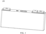
- the energy-storage apparatus 100 includes an electrode assembly 20, a housing 30, and an end cover assembly 10.
- the electrode assembly 20 is located in the housing 30.
- the end cover assembly 10 is electrically connected to the electrode assembly 20.
- the end cap assembly 10 covers an opening of the housing 30 to enclose the housing 30.
- the end cover assembly 10 includes a main cover plate 14 and an explosion-proof-valve holder 12.
- the middle of the main cover plate 14 defines an explosion-proof opening (not illustrated) for mounting an explosion-proof sheet (not illustrated).
- the explosion-proof sheet is fixed in the explosion-proof opening of the main cover plate 14 to seal the explosion-proof opening.
- the explosion-proof sheet may be fixed in the explosion-proof opening of the main cover plate 14 via soldering.
- the explosion-proof-valve holder 12 may be made of a metal material.
- An insulation holder 11 in the energy-storage apparatus 100 is provided in embodiments of the disclosure. As illustrated in FIG. 4 and FIG. 5 , the insulation holder 11 is a portion of the end cover assembly 10.
- the insulation holder 11 includes a main body plate 111, a first wall plate 112, and a second wall plate 113.
- the insulation holder 11 is made of an insulation material, and may specifically be made of plastic, such as polypropylene (PP).
- the main body plate 111 includes a first surface 1111 and a second surface 1112 opposite to the first surface 1111.
- the second surface 1112 faces the electrode assembly 20 of the energy-storage apparatus 100.
- the main body plate 111 is in a shape of a plate and has a convex plate-surface.
- the main body plate 111 has a length, a width, and a thickness. In subsequent illustration of various structures, an extension direction of the length of the main body plate 111 serves as a length direction, an extension direction of the width of the main body plate 111 serves as a width direction, and an extension direction of the thickness of the main body plate 111 serves as a thickness direction.
- the first surface 1111 is opposite to the second surface 1112 in the thickness direction.
- the main cover plate 14 faces the first surface 1111.
- the main cover plate 14 may be parallel to the main body plate 111.
- the explosion-proof-valve holder 12 is located between the main body plate 111 and main cover plate 14.
- the first wall plate 112 and the second wall plate 113 are provided on the first surface 1111 and face each other in the length direction of the main body plate 111.
- the main body plate 111 is divided into a left part, a middle part, and a right part sequentially in the length direction.
- the first wall plate 112 and the second wall plate 113 are connected to the middle part.
- the first wall plate 112 and the second wall plate 113 both are in a shape of a plate.
- the first wall plate 112, the second wall plate 113, and the main body plate 111 may be integrally formed, for example, be integrally formed through injection molding.
- the first wall plate 112 bends and extends away from the second wall plate 113 in the thickness direction of the main body plate 111.
- the second wall plate 113 bends and extends away from the first wall plate 112 in the thickness direction of the main body plate 111.
- the main body plate 111, the first wall plate 112, and the second wall plate 113 jointly define a receiving space 114.
- the receiving space 114 is used for receiving the explosion-proof-valve holder 12.
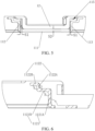
- the main body plate 111, the first wall plate 112, and the second wall plate 113 are all spaced apart from the explosion-proof-valve holder 12 to form a first airflow channel 115.
- a curved extension path of the first wall plate 112 may be wave-like or serrated.
- a curved extension path of the second wall plate 113 may be wave-like or serrated.
- the shape of the curved extension path of the first wall plate 112 may be the same as or different from the shape of the curved extension path of the second wall plate 113.
- a size of the explosion-proof-valve holder 12 may be smaller than a volume of the receiving space 114, and a shape of the explosion-proof-valve holder 12 may be similar to a shape of the receiving space 114, so that the main body plate 111, the first wall plate 112, and the second wall plate 113 are all spaced apart from the explosion-proof-valve holder 12 to form the first airflow channel 115. Furthermore, in a cross-sectional view of the end cover assembly 10 taken along the thickness direction of the main body plate 111, the first airflow channel 115 may be curved.
- the receiving space 114 is divided by the explosion-proof-valve holder 12 to form the first airflow channel 115, so the first airflow channel 115 is always part of the receiving space 114.
- the first airflow channel 115 may extend in a shape of a Chinese character "JL" or a letter "U". It can be understood that, since the first airflow channel 115 is defined by the main body plate 111, the first wall plate 112, the second wall plate 113, and the explosion-proof-valve holder 12, the extension shape of the first airflow channel 115 may be similar to the shape of the cross section of the whole formed by the main body plate 111, the first wall plate 112, and the second wall plate 113 that are connected together.
- the first wall plate 112 and the second wall plate 113 facing the first wall plate 112 are provided on the main body plate 111, the main body plate 111, the first wall plate 112, and the second wall plate 113 jointly define the receiving space 114, and the explosion-proof-valve holder 12 is received in the receiving space 114, and thus the explosion-proof-valve holder 12 may be surrounded and protected by the main body plate 111, the first wall plate 112, and the second wall plate 113.
- the explosion-proof-valve holder 12 may be isolated from the electrode assembly 20 by the main body plate 111, the first wall plate 112, and the second wall plate 113, and thus the explosion-proof-valve holder 12 may be prevented from contacting the electrode assembly 20 to avoid short circuit, and impurities outside the explosion-proof-valve holder 12 may be prevented from entering the electrode assembly 20.
- both the first wall plate 112 and the second wall plate 113 are curved, so that the curved first airflow channel 115 may be formed among the explosion-proof-valve holder 12, the main body plate 111, the first wall plate 112, and the second wall plate 113 in the case where the explosion-proof-valve holder 12 is received in the receiving space 114, so as to facilitate sufficient air flow.
- the first wall plate 112 extends away from the second wall plate 113
- the second wall plate 113 extends away from the first wall plate 112, and thus the first airflow channel 115 at the first wall plate 112 and the second wall plate 113 may be sloped, which may facilitate air convergence in a space between the explosion-proof-valve holder 12 and the main cover plate 14.
- the first wall plate 112 and the second wall plate 113 are both spaced apart from the explosion-proof-valve holder 12 by a distance S1 ranging from 0.15 mm to 2.65 mm in a length direction of the main body plate 111.
- the spacing distance S1 may be 0.95 mm, 1.05 mm, 1.1 mm, 1.25 mm, or 1.3 mm. With aid of the spacing distance S1 that is in the range, it may facilitate flow of air to the receiving space 114 through the first airflow channel 115, and other foreign matters can be prevented from entering the airflow channel. In the case where the spacing distance S1 is less than 0.15 mm, the spacing is too small to form an airflow channel for air to flow freely.
- the spacing distance S1 is greater than 2.65 mm, the spacing is too large, and thus foreign matters in the end cover assembly 10, such as a broken tab or a broken insulation film, may easily enter the airflow channel and drift into the receiving space 114 in an airflow direction, resulting in failure of the explosion-proof valve.
- the first wall plate 112 includes a first curved plate 1121 and a second curved plate 1122.
- One end of the first curved plate 1121 is connected to the first surface 1111, and another end of the first curved plate 1121 extends away from the second wall plate 113.
- One end of the second curved plate 1122 is connected to one end of the first curved plate 1121 away from the main body plate 111, i.e., connected to the another end of the first curved plate 1121 extending away from the second wall plate 113, and another end of the second curved plate 1122 extends away from the second wall plate 113.
- the cross section of the first curved plate 1121 and the cross section of the second curved plate 1222 may both be in a shape of a smooth curve. It may be understood that, by means of that the first curved plate 1121 and the second curved plate 1122 both are in the shape of a smooth curve, it may be beneficial for smooth air flow, and thus air turbulence in the first airflow channel 115 may be avoided. Meanwhile, since the first curved plate 1121 and the second curved plate 1122 are both in the shape of a smooth curve, scratching of the first wall plate 112 may be avoided in use and accordingly burrs on the first wall plate 112 may be avoided.
- the cross section of the first curved plate 1121 and the cross section of the second curved plate 1122 may both have a sharp angle.
- the insulation holder 11 may be formed by inversion molding. In the case where the first curved plate 1121 and the second curved plate 1122 both have a sharp angle, edge chamfering for a mold may be not needed, and thus it may facilitate manufacturing of the mold.
- the shape of the cross section of the first curved plate 1121 may be the same as or different from the shape of the cross section of the second curved plate 1122.
- the cross section of the first curved plate 1121 may have a sharp angle
- the cross section of the second curved plate 1122 may be in a shape of a smooth curve, which may be specifically designed according to requirements.
- the second wall plate 113 may include a third curved plate (not illustrated) and a fourth curved plate (not illustrated).
- One end of the third curved plate is connected to the first surface 1111, and another end of the third curved plate extends away from the first wall plate 112.
- One end of the fourth curved plate is connected to one end of the third curved plate away from the main body plate 111, and another end of the fourth curved plate extends away from the first wall plate 112.
- the cross section of the third curved plate may be in a shape of a smooth curve or have a sharp angle
- the cross section of the fourth curved plate may be in a shape of a smooth curve or have a sharp angle.
- the first wall plate 112 includes the first curved plate 1121 and the second curved plate 1122, one end of the first curved plate 1121 extends away from the second wall plate 113, and one end of the second curved plate 1122 extends away from the second wall plate 113, and thus the first wall plate 112 may have a structure of at least two steps, facilitating uniform and smooth air flow
- the first curved plate 1121 may include a first plate 1121A and a second plate 1121B connected with each other at an angle.
- the first plate 1121A is connected to the first surface 1111 and extends in the thickness direction of the main body plate 111.
- the second plate 1121B extends away from the second wall plate 113.
- first plate 1121A and the main body plate 111 are connected with each other at an angle.
- a connection angle defined between the first plate 1121A and the main body plate 111 may be a first angle ⁇ that may be 90°.
- the first angle ⁇ may be 80°, 85°, 95°, or 100°. It can be understood that the first plate 1121A is connected to the first surface 1111 and may extend in the thickness direction of the main body plate 111.
- the angle defined between the first plate 1121A and the main body plate 111 may not be limited, but the angle may not be too large or too small.
- the first wall plate 112 has an insufficient size in the thickness direction of the main body plate 111, and thus the first wall plate 112 as a whole has relatively poor support for the insulation holder 11, so that the insulation holder 11 is insufficiently stable.
- the second plate 1121B and the first plate 1121A are connected with each other at an angle.
- a connection angle defined between the second plate 1121B and the first plate 1121A may be a second angle ⁇ that may be 100°.
- the second included angle ⁇ may be 90°, 95°, 105°, or 110°. It may be understood that the second plate 1121B is connected to a surface of the first plate 1121A away from the second wall plate 113 and extends away from the second wall plate 113, and the angle defined between the second plate 1121B and the first plate 1121A may not be limited.
- the second angle ⁇ is greater than 90°, it may facilitate air flow in the first airflow channel 115, so that air tends to flow towards the main body plate 111.
- the connection angle defined between the second plate 1121B and the first plate 1121 A may not be too large or too small. In the case where the connection angle is too small, the second plate 1121B is too close to the surface of the first plate 1121A away from the second wall plate 113, resulting in that the curved first airflow channel 115 cannot be formed. In the case where the connection angle is too large, the second plate 1121B is substantially parallel to the first plate 1121A, resulting in that the curved first air flow channel 115 cannot be formed.
- two opposite surfaces of the first plate 1121A may be flat surfaces that are parallel to each other, or one of the two opposite surfaces of the first plate 1121A may be a curved surface that is outwardly convex, or both of the two opposite surfaces of the first plate 1121A may be curved surfaces that are outwardly convex.
- Two opposite surfaces of the second plate 1121B may be flat surfaces that are parallel to each other, or one of the two opposite surfaces of the second plate 1121B may be a curved surface that is outwardly convex, or both of the two opposite surfaces of the second plate 1121B may be curved surfaces that are outwardly convex.
- the first plate 1121A and the second plate 1121B may be connected with each other at a right angle, so that it may facilitate matching of an appearance structure of the explosion-proof-valve holder 12 with the structure of the first plate 1121A and the second plate 1121B, thereby forming the first airflow channel 115. Meanwhile, the first plate 1121A extends in the thickness direction of the main body plate 111, and the second plate 1121B extends away from the second wall plate 113, so that the first curved plate 1121 has a stepped structure, which may be beneficial for air to flow to the space between the explosion-proof-valve holder 12 and the main cover plate 14.
- the second curved plate 1122 may include a third plate 1122A and a fourth plate 1122B connected with each other at an angle.
- the third plate 1122A extends in the thickness direction of the main body plate 111, and the third plate 1122A and the first curved plate 1121 are connected with each other at an angle.
- the fourth plate 1122B extends away from the second wall plate 113.
- a connection angle defined between the third plate 1122A and the second plate 1121B may be a third angle ⁇ that may be 90°.
- the third angle ⁇ may be 80°, 85°, 95°, or 100°. It can be understood that the third plate 1122A is connected to a surface of the second plate 1121B away from the main body plate 111 and may extend in the thickness direction of the main body plate 111.
- the angle defined between the third plate 1122A and the second plate 1121B may not be limited, but the angle may not be too large or too small.
- connection angle defined between the third plate 1122A and the second plate 1121B is too large or too small, the curved first airflow channel 115 cannot be formed, and the first wall plate 112 has an insufficient size in the thickness direction of the main body plate 111, and thus the first wall plate 112 as a whole has relatively poor support for the insulation holder 11.
- a connection angle defined between fourth plate 1122B and the third plate 1122A may be a fourth angle ⁇ that may be 100°.
- the fourth angle ⁇ may be 90°, 95°, 105°, or 110°. It may be understood that the fourth plate 1122B is connected to a surface of the third plate 1122A away from the second wall plate 113 and extends away from the second wall plate 113, and the angle defined between the fourth plate 1122B and the third plate 1122A may not be limited.
- the fourth included angle ⁇ is greater than 90°, it may facilitate air flow in the first airflow channel 115, so that air tends to flow towards the main body plate 111.
- the connection angle defined between the fourth plate 1122B and the third plate 1122A may not be too large or too small. In the case where the connection angle defined between the fourth plate 1122B and the third plate 1122A is too large or too small, the curved first airflow channel 115 cannot be formed.
- two opposite surfaces of the third plate 1122A may be flat surfaces that are parallel to each other, or one of the two opposite surfaces of the third plate 1122A may be a curved surface that is outwardly convex, or both of the two opposite surfaces of the third plate 1122A may be curved surfaces that are outwardly convex.
- Two opposite surfaces of the fourth plate 1122B may be flat surfaces that are parallel to each other, or one of the two opposite surfaces of the fourth plate 1122B may be a curved surface that is outwardly convex, or both of the two opposite surfaces of the fourth plate 1122B may be curved surfaces that are outwardly convex.
- the third plate 1122A and the fourth plate 1122B may be connected with each other at a right angle, or the connection angle defined between the fourth plate 1122B and the third plate 1122A may be 100°, so that the fourth plate 1122B and the third plate 1122A may form a sloped step, and thus air around the fourth plate 1122B may easily flow downwards to the first curved plate 1121 through the sloped step, thereby improving mobility of air and air convergence.
- the insulation holder 11 may further include a lateral plate 116.
- the lateral plate 116 is connected to one end of the main body plate 111 in the width direction of the main body plate 111.
- the lateral plate 116 extends in the thickness direction of the main body plate 111.
- the main body plate 111 has a chamfered edge at an end away from the lateral plate 116.
- the lateral plate 116 and the main plate 111 are connected with each other at an angle.
- a connection angle defined between the lateral plate 116 and the main body plate 111 may be 90°.
- the lateral plate 116 extends in the thickness direction of the main body plate 111.
- the first wall plate 112 and the second wall plate 113 both are connected to the lateral plate 116.
- the lateral plate 116, the first wall plate 112, and the second wall plate 113 jointly define the receiving space 114.
- the main body plate 111 has a first edge (not illustrated), a second edge (not illustrated), and a third edge (not illustrated) that are connected in sequence.
- the lateral plate 116 is connected to the third edge of the main body plate 111.
- the third edge is opposite to the first edge.
- Both the second edge and the first edge may be a chamfered edge, so that during assembling the insulation holder 11 to the housing 30, a tab can be prevented from being scratched to avoid breakage of the tab.
- the insulation holder 11 is provided with the lateral plate 116 that is connected to the main body plate 111, and the lateral plate 116 is connected to both the first wall plate 112 and the second wall plate 113, so that the lateral plate 116 may support and reinforce both the first wall plate 112 and the second wall plate 113 and can also protect other components of the end cover assembly 10 from the side.
- the main body plate 111 has a chamfered edge at an end away from the lateral plate 116, so that an excessive sharp edge of the main body plate 111 may be avoided, thereby avoiding scratching and breakage of the tab during assembly.
- the insulation holder 11 may further include a protrusion 117.
- the protrusion 117 is connected to one end of the lateral plate 116 away from the main body plate 111.
- the protrusion 117 protrudes from the lateral plate 116 in the width direction of the main body plate 111 and faces the main body plate 111.
- An orthographic projection of the protrusion 117 on the main body plate 111 is in a shape of a trapezoid.
- the lateral plate 116 may have a connection surface 1161.
- the first wall plate 112 and the second wall plate 113 both are connected to the connection surface 1161.
- the protrusion 117 is connected to the connection surface 1161 and located at one end of the connection surface 1161 away from the main body plate 111.
- the protrusion 117 is in butt joint with an insulation member 13.
- the protrusion 117 protrudes from the connection surface 1161 in the width direction of the main body plate 111 and faces the main body plate 111. It may be understood that the protrusion 117 may be in a shape of a plate, and a plate surface of the protrusion 117 may be parallel to the plate surface of the main body plate 111.
- the orthographic projection of the protrusion 117 on the main body plate 111 is in the shape of a trapezoid and may specifically be in a shape of a right trapezoid.
- a relatively long bottom edge of the protrusion 117 may be connected to the lateral plate 116. Therefore, the protrusion 117 has a tapered shape, tapering in a direction away from the lateral plate 116.
- the orthographic projection of the protrusion 117 on the main body plate 111 may be in a shape of a hexagon.
- the protrusion 117 may have a chamfer at an end away from the lateral plate 116.
- the insulation holder 11 is provided with the protrusion 117 and the protrusion 117 is connected to the lateral plate 116, so that the protrusion 117 may be used for butt joint with other components of the end cover assembly 10, thereby enhancing stability of the end cover assembly 10.
- the orthographic projection of the protrusion 117 on the main body plate 111 is in the shape of a trapezoid, so that it may facilitate smooth butt joint with the protrusion 117, thereby improving reliability of the end cover assembly 10 during assembly of the end cover assembly 10.
- one end of the first wall plate 112 away from the main body plate 111 is spaced apart from the protrusion 117 by a spacing distance in the thickness direction of the main body plate 111.
- the first wall plate 112 may not exceed the lateral plate 116 in the thickness direction of the main body plate 111. It may be understood that when the first wall plate 112 and the protrusion 117 are observed in the length direction of the main body plate 111, it may be observed that one end of the first wall plate 112 may be misaligned with the protrusion 117, and the protrusion 117 does not block the first wall plate 112 in the length direction of the main body plate 111.
- the end of the first wall plate 112 away from the main body plate 111 is spaced apart from the protrusion 117 by a spacing distance in the thickness direction of the main body plate 111, so that the end of the first wall plate 112 away from the main body plate 111 and the protrusion 117 are misaligned, and thus when flowing to the first wall plate 112 in the length direction of the main body panel 111, air may not be blocked by the protrusion 117, and a layered airflow channel may be formed, thereby preventing air from impacting the protrusion 117 to avoid turbulence, and thus facilitating air convergence.
- the main body plate 111 may include a vent plate 1113.
- the vent plate 1113 defines a vent hole 1114.
- the first wall plate 112 is connected to one of two opposite ends of the vent plate 1113 in a length direction of the vent plate 1113, and the second wall plate 113 is connected to the other of the two opposite ends of the vent plate 1113 in the length direction of the vent plate 1113.
- the first wall plate 112, the second wall plate 113, and the vent plate 1113 jointly define the receiving space 114.
- the vent plate 1113 is spaced apart from the explosion-proof-valve holder 12 by a spacing distance.
- the vent plate 1113 is located in the middle of the main body plate 111 and defines the vent hole 1114 that penetrates the main body plate 111 in the thickness direction of the main body plate 111, so that the receiving space 114 may be in communication with the outside.
- the vent hole 1114 may be in a shape of a quadrangle, a circle, an ellipse, or other polygons, which is not limited herein.
- the vent plate 1113 may include two side plates (i.e., a left side plate and a right side plate) that are opposite to each other in the length direction of the vent plate 1113.
- the first wall plate 112 and the left side plate may be connected with each other at an angle
- the second wall plate 113 and the right side plate may be connected with each other at an angle, and for a specific angle, reference may be made to the foregoing embodiments.
- vent plate 1113 is spaced apart from the explosion-proof-valve holder 12 by a spacing distance, and the vent hole 1114 faces the explosion-proof-valve holder 12.
- the explosion-proof-valve holder 12 may provide buffering support for the vent plate 1113 that has a relatively low structural strength.
- electrolyte may move upwards and the vent plate 1113 may be subject to an impact force from the electrolyte.
- the vent plate 1113 tilts upwards in the spacing distance to absorb energy.
- the vent plate 1113 tilts upwards until the vent plate 1113 abuts against the explosion-proof-valve holder 12, so that the vent plate 1113 may be prevented from excessively tilting to avoid breakage of the vent plate 1113, thereby avoiding a broken fragment of the vent plate 1113 and accordingly avoiding scratching of the tab.
- the main body plate 111 includes the vent plate 1113 that is used for defining the receiving space 114, and the vent plate 1113 defines the vent hole 1114 in communication with the receiving space 114, and thus the receiving space 114 may be in communication with the outside through the vent hole 1114, so that air generated by the electrode assembly 20 may flow out of the housing 30 through the vent hole 1114.
- the main body plate 111 is spaced apart from the explosion-proof-valve holder 12 by a spacing distance S2 ranging from 0.25 mm to 3.45 mm.
- the spacing distance S2 may be 1.3 mm, 1.4 mm, 1.5 mm, 1.6 mm, or 1.7 mm. With aid of the spacing distance S2 that is in the range, it may facilitate flow of air to the receiving space 114 through the first airflow channel 115, and other foreign matters may be prevented from entering the airflow channel. In the case where the spacing distance S2 is less than 0.25 mm, the spacing is too small to form an airflow channel for air to flow freely.
- the spacing distance S2 is greater than 3.45 mm, the spacing is too large, and thus foreign matters in the end cover assembly 10, such as a broken tab or a broken insulation film, may easily enter the airflow channel and drift into the receiving space 114 in an airflow direction, resulting in failure of the explosion-proof valve.
- the insulation holder 11 may further include at least one rib 1115.
- the at least one rib 1115 is located in the vent hole 1114 and divides the vent hole 1114 into multiple air sub-holes 1114A.
- the rib 1115 extends in the width direction of the vent plate 1113. Two ends of the rib 1115 are respectively connected to an upper side plate and a lower side plate that jointly define the vent hole 1114.
- the upper side plate is connected to both the left side plate and the right side plate, and the lower side plate is connected to both the left side plate and the right side plate. Therefore, the rib 1115 may divide the vent hole 1114 into the multiple air sub-holes 1114A.
- each two adjacent ribs 1115 may be spaced apart from each other by a same spacing.
- a distance between one of two outermost ribs 1115 and the left side plate may be the same as a distance between the other of the two outermost ribs 1115 and the right side plate.
- the multiple air sub-holes 1114A may be the same as each other in size.
- the vent hole 1114 may be divided to form uniform air flow. Meanwhile, the rib 1115 may help to support the vent plate 1113 that defines the vent hole 1114, and may also be used to block debris.
- the main body plate 111 may further include a support plate 1116.
- the vent plate 1113 may include a first vent plate 1113A and a second vent plate 1113B.
- the support plate 1116 and the first vent plate 1113A are sequentially connected in the length direction of the main body plate 111.
- the first vent plate 1113 A and the second vent plate 1113B are in butt joint in the width direction of the main body plate 111.
- the second vent plate 1113B protrudes from the support plate 1116 in the width direction of the main body plate 111.
- the support plate 1116 may further include a left support plate 1116A and a right support plate 1116B.
- the left support plate 1116A is connected to the left side plate mentioned in the foregoing embodiments
- the right support plate 1116B is connected to the right side plate mentioned in the foregoing embodiments.
- the left support plate 1116A and the right support plate 1116B may both define the vent hole mentioned in the foregoing embodiments.
- the vent plate 1113 may be divided into the first vent plate 1113A and the second vent plate 1113B in the width direction of the vent plate 1113.
- the first vent plate 1113A and the second vent plate 1113B are in butt joint to define the vent hole 1114.
- the first vent plate 1113 A may include the upper side plate, part of the left side plate, and part of the right side plate that are mentioned in the foregoing embodiments.
- the second vent plate 1113B may include the lower side plate, part of the left side plate, and part of the right side plate that are mentioned in the foregoing embodiments.
- the left support plate 1116A, the first vent plate 1113A, and the right support plate 1116B are sequentially connected in the length direction of the main body plate 111.
- the second vent plate 1113B protrudes from the support plate 1116 in the width direction of the main body plate 111.
- the vent plate 1113 may be integrally formed, and the vent plate 1113 being divided into the first vent plate 1113A and the second vent plate 1113B is mainly for ease of illustration.
- the second vent plate 1113B is positioned protruding out of the support plate 1116 in the width direction of the main body plate 111, so that the vent plate 1113 may have a relatively large size, and thus the vent hole 1114 may be relatively large to improve air flow
- the second vent plate 1113B has a third surface 1117 opposite to the first surface 1111.
- the first wall plate 112 has a fourth surface 1123.
- the third surface 1117 is connected to the fourth surface 1123.
- a chamfer is formed between the third surface 1117 and the fourth surface 1123.
- the first vent plate 1113A may include part of the second surface 1112.
- the second vent plate 1113B may include part of the second surface 1112 and the third surface 1117.
- the third surface 1117 may be not parallel to the second surface 1112.
- a fifth included angle ⁇ may be defined between the second surface 1112 and the third surface 1117.
- the third surface 1117 is inclined downwards relative to the second surface 1112 and is used for guiding air flow.
- the fourth surface 1123 may be a surface of the first plate 1121A opposite the second wall plate 113 mentioned in the foregoing embodiments. Hence, the fourth surface 1123 is connected to the third surface 1117, and a chamfer is formed between the third surface 1117 and the fourth surface 1123.
- the chamfer formed between the fourth surface 1123 of the first wall plate 112 and the third surface 1117 of the second vent plate 1113B opposite the first surface 1111 it may facilitate air flow below the vent plate 1113, thereby guiding air outside the receiving space 114 to circulate internally and externally through the first wall plate 112 and the second wall plate 113.
- the second wall plate 113 and the first wall plate 112 are in mirror symmetry with respect to a symmetry plane.
- the insulation holder 11 may be of a structure in mirror symmetry, and a symmetry plane of the insulation holder 11 may be located in the middle of the insulation holder 11.
- the insulation holder 11 may be divided into a left part and a right part by a plane that is perpendicular to the main body plate 111 and passes through the middle of the main body plate 111 positioned in the length direction of the main body plate 111, and the left part and the right part may be in mirror symmetry relative to the plane.
- the plane may be a symmetry plane.
- the first wall plate 112 is located at the left end
- the second wall plate 113 is located at the right end
- the second wall plate 113 and the first wall plate 112 are in mirror symmetry.
- the protrusion 117 mentioned in the forgoing embodiments may be implemented as two protrusions 117, and the two protrusions 117 may be in mirror symmetry.
- the left support plate 1116A and the right support plate 1116B mentioned in the forgoing embodiments may be in mirror symmetry.
- the second wall plate 113 and the first wall plate 112 may be in mirror symmetry, so that the first airflow channel 115 may be of a symmetrical structure, thereby reducing the number of molds for manufacturing the insulation holder 11, and improving the production efficiency of components of the insulation holder 11, and thus saving manufacturing cost.
- the main body plate 111 defines a first notch 118.
- the explosion-proof-valve holder 12 defines a second notch 121.
- the first notch 118 is aligned with the second notch 121 in the thickness direction of the main body plate 111.
- the left side plate mentioned in the foregoing embodiments may have a first sidewall (not illustrated), and the right side plate mentioned in the foregoing embodiments may have a second sidewall (not illustrated).
- the first sidewall is opposite to the second sidewall, and the first sidewall and the second sidewall jointly define the vent hole 1114.
- the first sidewall is at least partially recessed in the length direction of the vent plate 1113 to define one first notch 118
- the second sidewall is at least partially recessed in the length direction of the vent plate 1113 to define one first notch 118, and thus there may be two first notches 118.
- the two first notches 118 may both be in communication with the vent hole 1114.
- the explosion-proof-valve holder 12 may include a baffle 122, a first connection plate 123, and a second connection plate 124.
- the baffle 122 faces the main body plate 111 and the main cover plate 14.
- the first connection plate 123 is connected to one of two opposite ends of the baffle 122 in a length direction of the baffle 122
- the second connection plate 124 is connected to the other of the two opposite ends of the baffle 122 in the length direction of the baffle 122.
- the first connection plate 123 and the second connection plate 124 are both further connected to the main cover plate 14.
- the explosion-proof-valve holder 12 may be of a structure in mirror symmetry, and a symmetry plane of the explosion-proof-valve holder 12 may be the same as the symmetry plane of the insulation holder 11 mentioned in the foregoing embodiments.
- the cross section of the explosion-proof-valve holder 12 in the thickness direction of the main body plate 111 may be in a shape of a Chinese character " ". It may be understood that the first connection plate 123 and the second connection plate 124 may both be curved plates.
- the second notch 121 penetrates two opposite surfaces of the baffle 122 and is aligned with the first notch 118.
- the main body plate 111 defines the first notch 118
- the explosion-proof-valve holder 12 defines the second notch 121
- the first notch 118 is aligned with the second notch 121, so that a vertical airflow channel can be formed in the receiving space 114, thereby improving the number of channels for air convergence, and finally improving air flow density near the explosion-proof-valve holder 12.
- the insulation holder 11 may further include the lateral plate 116 and a fastener 119.
- the lateral plate 116 is connected to one end of the main body plate 111 in the width direction of the main body plate 111.
- the lateral plate 116 extends in the thickness direction of the main body plate 111.
- the fastener 119 is positioned protruding out of the lateral plate 116 and is received in the receiving space 114.
- the fastener 119 is engaged with the explosion-proof-valve holder 12 to fix the insulation holder 11 with the explosion-proof-valve holder 12.
- the fastener 119 protrudes from the connection surface 1161 of the lateral plate 116 and is located in the receiving space 114.
- the fastener 119 may be in a shape of "1" so that the fastener 119 can be engaged with the explosion-proof-valve holder 12.
- the insulation holder 11 has a structure in mirror symmetry, there may be two fasteners 119, and the two fasteners 119 are in mirror symmetry.
- the explosion-proof-valve holder 12 further defines two fixing holes 125, where one of the two fixing holes 125 is defined on the first connection plate 123, and the other of the two fixing holes 125 is defined on the second connection plate 124. Since the explosion-proof-valve holder 12 has a structure in mirror symmetry, the first connection plate 123 is taken as an example.
- the fixing hole 125 penetrates two opposite surfaces of the first connection plate 123, and the fastener 119 at least partially extends into the fixing hole 125 to be fixedly connected to the first connection plate 123.
- the fastener 119 may be aligned with both the first notch 118 and the second notch 121 mentioned in the foregoing embodiments, so that whether the fasteners 119 are snap-fitted with the first connection plate 123 and the second connection plate 124 may be observed through the first notches 118.
- the explosion-proof-valve holder 12 may be fixed to the insulation holder 11 via the fastener 119.
- the end cover assembly 10 may further include the insulation member 13.
- the insulation member 13 is connected to the insulation holder 11 and may include a side plate 132 facing the explosion-proof-valve holder 12.
- the side plate 132 defines a third notch 134.
- the insulation member 13 may include a positive-electrode cover plate 13A and a negative-electrode cover plate 13B.
- the positive-electrode cover plate 13A and the negative-electrode cover plate 13B both are connected to the insulation holder 11.
- the positive-electrode cover plate 13A and the negative-electrode cover plate 13B are opposite to each other in the length direction of the main body plate 111.
- the positive-electrode cover plate 13A and the negative-electrode cover plate 13B both are made of an insulation material, and may specifically be made of plastic, such as PP.
- the positive-electrode cover plate 13A and the negative-electrode cover plate 13B both are substantially in a shape of a plate and have a substantially rectangular plate surface.
- the positive-electrode cover plate 13A and the negative-electrode cover plate 13B both are consistent with the main body plate 111 in a length direction, a width direction, and a thickness direction.
- the positive-electrode cover plate 13A may include a base 131 and the side plate 132.
- the base 131 may be in a shape of a plate and has a rectangular plate surface.
- a length direction, a width direction, and a thickness direction of the base 131 are the foregoing length direction, the width direction, and the thickness direction of the positive-electrode cover plate 13A, respectively.
- the side plate 132 may be in a shape of a plate, a strip, a block, etc., which is not limited herein.
- the side plate 132 and the base 131 may be integrally formed, for example, be integrally formed through injection molding.
- the side plate 132 is positioned at one end of the base 131 close to the negative-electrode cover plate 13B in the length direction of the base 131.
- the base 131 defines a liquid injection hole 133 in the thickness direction of the base 131.
- the liquid injection hole 133 is close to the side plate 132, and the side plate 132 is configured to define the liquid injection hole 133, and thus the liquid injection hole 133 has at least one straight edge.
- the side plate 132 is close to one end of the first wall plate 112 away from the main body plate 111, and the side plate 132 recesses towards a surface of the side plate 132 connected to the base 131 to define the third notch 134.
- the explosion-proof-valve holder 12 is located in the receiving space 114, and the third notch 134 is in communication with the first airflow channel 115.
- the third notch 134 is defined on the side plate 132 of the insulation member 13 facing the explosion-proof-valve holder 12, so that the liquid injection hole 133 of the insulation member 13 may be in communication with the first airflow channel 115 through the third notch 134, thereby increasing an airflow path and improving air flow in the end cover assembly 10.
- the insulation holder 11 may include a first holder 11A and a second holder 11B.
- the first holder 11A is connected to one of two opposite sides of the insulation member 13 in a width direction of the insulation member 13, and the second holder 11B is connected to the other of the two opposite sides of the insulation member 13 in the width direction of the insulation member 13.
- the first holder 11A and the second holder 11B are in mirror symmetry.
- the first holder 11A is spaced apart from the second holder 11B by a spacing distance to form a second airflow channel 115.
- the third notch 134 faces and is in communication with the second airflow channel 11S.
- the end cover assembly 10 may include two holders 11, i.e., the first holder 11A and the second holder 11B.
- the first holder 11A and the second holder 11B are in mirror symmetry. Therefore, the first holder 11A and the second holder 11B both have all the features of the holder 11 mentioned in the above embodiments.
- the first holder 11A defines a receiving space 114A
- the second holder 11B defines a receiving space 114B.
- the receiving space 114A and the receiving space 114B together form the receiving space 114.
- the explosion-proof-valve holder 12 is received in the receiving space 114.
- the first holder 11A is spaced apart from the second holder 11B by a spacing distance to form the second airflow channel 11S.
- An extension path of the second airflow channel 11S may be the same as and faces the extension path of the first airflow channel 115. Therefore, the second airflow channel 11S is in communication with the receiving space 114.
- the insulation member 13 is located between the first holder 11A and the second holder 11B and is connected to both the first holder 11A and the second holder 11B.
- the third notch 134 faces and is in communication with the second airflow channel 11S.
- the insulation holder 11 includes the first holder 11A and the second holder 11B that are in mirror symmetry, so that the insulation member 13 may be fixed and the explosion-proof-valve holder 12 may be protected via the first holder 11A and the second holder 11B. Meanwhile, the second airflow channel 11S formed by the first holder 11A and the second holder 11B that are spaced apart from each other by a spacing distance may be in communication with the third notch 134, thereby increasing the number of channels for air convergence, reducing the number of molds for manufacturing the insulation holder 11, and improving the production efficiency of components of the insulation holder 11, and thus saving manufacturing cost.
- the first holder 11A is spaced apart from the second holder 11B by a spacing distance S3 ranging from 0.55 mm to 5.25 mm.
- the spacing distance S3 may be 1.6 mm, 1.7 mm, 1.85 mm, 1.95 mm, or 2.0 mm. With aid of the spacing distance S3 that is in the range, it may facilitate flow of air to the receiving space 114 through the second airflow channel 11S, and other foreign matters can be prevented from entering the airflow channel. In the case where the spacing distance S3 is less than 0.55 mm, the spacing is too small to form the airflow channel for air to flow freely.
- the spacing distance S3 is greater than 5.25 mm, the spacing is too large, and thus foreign matters in the end cover assembly 10, such as a broken tab or a broken insulation film, may easily enter the airflow channel and drift into the receiving space 114 in an airflow direction, resulting in failure of the explosion-proof valve.
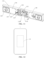
- an electricity-consumption device 1 is further provided in embodiments of the disclosure.
- the electricity-consumption device 1 includes the energy-storage apparatus 100 in the embodiments of the disclosure.
- the energy-storage apparatus 100 is configured to power the electricity-consumption device 1.
- orientations or position relationships indicated by terms such as “center”, “on”, “above”, “under”, “below”, “beneath”, “left”, “right”, “vertical”, “horizontal”, “in”, “inside”, “out”, “outside”, and the like may refer to orientations or position relationships indicated in the accompanying drawings and are only for the convenience of illustration of the disclosure and simplicity of illustration, rather than explicitly or implicitly indicate that apparatuses or components referred to herein must have a certain orientation or be configured or operated in a certain orientation and therefore cannot be understood as limitations to the disclosure.
Landscapes
- Chemical & Material Sciences (AREA)
- Chemical Kinetics & Catalysis (AREA)
- Electrochemistry (AREA)
- General Chemical & Material Sciences (AREA)
- Inorganic Chemistry (AREA)
- Battery Mounting, Suspending (AREA)
- Gas Exhaust Devices For Batteries (AREA)
Abstract
Description
- This disclosure relates to the field of energy-storage technologies, and in particular, to an end cover assembly, an energy-storage apparatus, and an electricity-consumption device.
- Energy-storage apparatuses may be configured to store energy and release energy when required. Current energy-storage apparatuses are mainly rechargeable secondary batteries. At present, a common secondary battery may mainly include a housing, an electrode assembly, and a cover assembly. The electrode assembly is received in the housing. The housing is enclosed by the cover assembly. A tab of the electrode assembly is connected to a terminal post on the cover assembly.
- In a secondary battery, due to its own manufacturing defects or under excitation of external temperature abnormalities, mechanical abnormalities, charging abnormalities, etc., irreversible side reactions, such as solid electrolyte interphase (SEI) film decomposition, positive-electrode material decomposition, and electrolyte decomposition, may occur inside the battery, and thus a large amount of heat may be generated, and small molecular gases may be released. Under special conditions (such as high temperature, short circuit, vibration, extrusion, and impact), gas expansion or smoke may easily occur, and fire or other thermal runaway may even occur, and thus there may be a certain safety hazard.
- An end cover assembly, an energy-storage apparatus, and an electricity-consumption device are provided in the disclosure, which aim to improve safety performance.
- To achieve the purpose of the disclosure, the disclosure provides the following technical solutions.
- In a first aspect, an end cover assembly is provided in the disclosure. The end cover assembly is for an energy-storage apparatus. The end cover assembly includes an explosion-proof-valve holder and an insulation holder. The insulation holder includes a main body plate, a first wall plate, and a second wall plate. The main body plate includes a first surface and a second surface. The second surface faces an electrode assembly of the energy-storage apparatus. The first wall plate and the second wall plate are provided on the first surface and opposite to each other in a length direction of the main body plate. The first wall plate extends away from the second wall plate in a thickness direction of the main body plate. The second wall plate extends away from the first wall plate in the thickness direction of the main body plate. The main body plate, the first wall plate, and the second wall plate jointly define a receiving space. The receiving space is used for receiving the explosion-proof-valve holder. The main body plate, the first wall plate, and the second wall plate are all spaced apart from the explosion-proof-valve holder to form a first airflow channel. The first wall plate and the second wall plate are both spaced apart from the explosion-proof-valve holder by a spacing distance S1 ranging from 0.95 mm to 2.65 mm in the length direction of the main body plate. The insulation holder includes a first holder and a second holder, where the first holder and the second holder are in mirror symmetry, the first holder is spaced apart from the second holder to form a second airflow channel, and the first holder is spaced apart from the second holder by a spacing distance S3 ranging from 1.6 mm to 5.25 mm. The main body plate defines a vent hole, where an inner wall of the vent hole is recessed in the length direction of the main body plate to define a first notch. The explosion-proof-valve holder includes a baffle, where the baffle faces the main body plate and the vent hole, an edge of the baffle is recessed in the length direction of the main body plate to define a second notch, and the first notch is aligned with the second notch in the thickness direction of the main body plate.
- The first wall plate and the second wall plate facing the first wall plate are provided on the main body plate, the main body plate, the first wall plate, and the second wall plate jointly define the receiving space, and the explosion-proof-valve holder is received in the receiving space, and thus the explosion-proof-valve holder may be surrounded and protected by the main body plate, the first wall plate, and the second wall plate. Furthermore, the explosion-proof-valve holder may be isolated from the electrode assembly by the main body plate, the first wall plate, and the second wall plate, and thus the explosion-proof-valve holder may be prevented from contacting the electrode assembly to avoid short circuit, and impurities outside the explosion-proof-valve holder may be prevented from entering the electrode assembly. Meanwhile, in the disclosure, both the first wall plate and the second wall plate are curved, so that the curved first airflow channel may be formed among the explosion-proof-valve holder, the main body plate, the first wall plate, and the second wall plate in the case where the explosion-proof-valve holder is received in the receiving space, so as to facilitate sufficient air flow. In addition, the first wall plate extends away from the second wall plate, and the second wall plate extends away from the first wall plate, and thus the first airflow channel at the first wall plate and the second wall plate may be sloped, which may facilitate air convergence at a position below the explosion-proof-valve holder.
- In an embodiment, the first wall plate and the second wall plate are both spaced apart from the explosion-proof-valve holder by a distance S1 ranging from 0.15 mm to 2.65 mm. With aid of the spacing distance S1 that is in the range, it may facilitate flow of air to the receiving space through the first airflow channel, and other foreign matters can be prevented from entering the airflow channel. In the case where the spacing distance S1 is less than 0.15 mm, the spacing is too small to form the airflow channel for air to flow freely. In the case where the spacing distance S1 is greater than 2.65 mm, the spacing is too large, and thus foreign matters in the end cover assembly, such as a broken tab or a broken insulation film, may easily enter the airflow channel and drift into the receiving space in an airflow direction, resulting in failure of the explosion-proof valve.
- In an embodiment, the first wall plate includes a first curved plate and a second curved plate. One end of the first curved plate is connected to the first surface, and another end of the first curved plate extends away from the second wall plate. One end of the second curved plate is connected to the another end of the first curved plate extending away from the second wall plate, and another end of the second curved plate extends away from the second wall plate. The first wall plate includes the first curved plate and the second curved plate, one end of the first curved plate extends away from the second wall plate, and one end of the second curved plate extends away from the second wall plate, and thus the first wall plate may have a structure of at least two steps, facilitating uniform and smooth air flow
- In an embodiment, the first curved plate includes a first plate and a second plate connected with each other at an angle. The first plate is connected to the first surface and extends in the thickness direction of the main body plate. The second plate extends away from the second wall plate. The first plate and the second plate may be connected with each other at a right angle, so that it may facilitate matching of an appearance structure of the explosion-proof-valve holder with the first plate and the second plate, thereby forming the first airflow channel. Meanwhile, the first plate extends in the thickness direction of the main body plate, and the second plate extends away from the second wall plate, so that the first curved plate has a stepped structure, which is beneficial for air to flow to a position below the explosion-proof-valve holder.
- In an embodiment, the second curved plate includes a third plate and a fourth plate connected with each other at an angle. The third plate extends in the thickness direction of the main body plate, and the third plate and the first curved plate are connected with each other at an angle. The fourth plate extends away from the second wall plate. The third plate and the fourth plate are connected with each other at a right angle, or the connection angle defined between the fourth plate and the third plate may be 100°, so that the fourth plate and the third plate may form a sloped step, and thus air around the fourth plate may easily flow downwards to the first curved plate through the sloped step, thereby improving mobility of air and air convergence.
- In an embodiment, the insulation holder further includes a lateral plate. The lateral plate is connected to one end of the main body plate in a width direction of the main body plate. The lateral plate extends in the thickness direction of the main body plate. The main body plate has a chamfered edge at an end away from the lateral plate. The insulation holder is provided with the lateral plate that is connected to the main body plate, and the lateral plate is connected to both the first wall plate and the second wall plate, so that the lateral plate can support and reinforce the first wall plate and the second wall plate and can also protect other components of the end cover assembly from the side. The main body plate has a chamfered edge at an end away from the lateral plate, so that an excessive sharp edge of the main body plate may be avoided, thereby avoiding scratching and breakage of the tab during assembly.
- In an embodiment, the insulation holder further includes a protrusion connected to one end of the lateral plate away from the main body plate. The protrusion protrudes from the lateral plate in the width direction of the main body plate and faces the main body plate. An orthographic projection of the protrusion on the main body plate is in a shape of a trapezoid. The insulation holder is provided with the protrusion and the protrusion is connected to the lateral plate, so that the protrusion may be used for butt joint with other components of the end cover assembly, thereby enhancing stability of the end cover assembly. Meanwhile, the orthographic projection of the protrusion on the main body plate is in the shape of a trapezoid, so that it may facilitate smooth butt joint with the protrusion, thereby improving reliability of the end cover assembly during assembly of the end cover assembly.
- In an embodiment, one end of the first wall plate away from the main body plate is spaced apart from the protrusion by a spacing distance in the thickness direction of the main body plate. The end of the first wall plate away from the main body plate is spaced apart from the protrusion by a spacing distance in the thickness direction of the main body plate, so that the end of the first wall plate away from the main body plate and the protrusion are misaligned, and thus when flowing to the first wall plate in the length direction of the main body panel, air may not be blocked by the protrusion, and a layered airflow channel can be formed, thereby preventing air from impacting the protrusion to avoid turbulence, and thus facilitating air convergence.
- In an embodiment, the main body plate includes a vent plate. The vent plate defines a vent hole. The first wall plate is connected to one of two opposite ends of the vent plate in a length direction of the vent plate, and the second wall plate is connected to the other of the two opposite ends of the vent plate in the length direction of the vent plate. The first wall plate, the second wall plate, and the vent plate jointly define the receiving space. The vent plate is spaced apart from the explosion-proof-valve holder by a spacing distance. The explosion-proof-valve holder can provide buffering support for the vent plate that has a relatively low structural strength. In the case where the energy-storage apparatus falls or suffers from collision, electrolyte may move upwards and the vent plate may be subject to an impact force from the electrolyte. In this case, the vent plate tilts upwards in the spacing distance to absorb energy. When the impact force is too large, the vent plate tilts upwards until the vent plate abuts against the explosion-proof-valve holder, so that the vent plate can be prevented from excessively tilting to avoid breakage of the vent plate, thereby avoiding a broken fragment of the vent plate and accordingly avoiding scratching of the tab. Therefore, safety performance of the energy-storage apparatus can be improved. The main body plate includes the vent plate that is used for defining the receiving space, and the vent plate defines the vent hole in communication with the receiving space, and thus the receiving space may be in communication with the outside through the vent hole, so that air generated by the electrode assembly can flow out of the housing through the vent hole.
- In an embodiment, the main body plate is spaced apart from the explosion-proof-valve holder by a spacing distance S2 ranging from 0.25mm to 3.45mm. With aid of the spacing distance S2 that is in the range, it may facilitate flow of air to the receiving space through the first airflow channel, and other foreign matters can be prevented from entering the airflow channel. In the case where the spacing distance S2 is less than 0.25 mm, the spacing is too small to form the airflow channel for air to flow freely. In the case where the spacing distance S2 is greater than 3.45 mm, the spacing is too large, and thus foreign matters in the end cover assembly, such as a broken tab or a broken insulation film, may easily enter the airflow channel and drift into the receiving space in an airflow direction, resulting in failure of the explosion-proof valve.
- In an embodiment, the insulation holder further includes at least one rib. The at least one rib is located in the vent hole and divides the vent hole into multiple air sub-holes. With aid of the rib in the vent hole, the vent hole may be divided to form uniform airflow. Meanwhile, the rib may help to support the vent plate that defines the vent hole, and may also be used to block debris.
- In an embodiment, the main body plate further includes a support plate. The vent plate includes a first vent plate and a second vent plate. The support plate and the first vent plate are sequentially connected in the length direction of the main body plate. The first vent plate and the second vent plate are in butt joint in the width direction of the main body plate. The second vent plate protrudes from the support plate in the width direction of the main body plate. The second vent plate protrudes from the support plate in the width direction of the main body plate, so that the vent plate may have a relatively large size, and thus the vent hole may be relatively large to improve air flow.
- In an embodiment, the second vent plate has a third surface opposite the first surface. The first wall plate has a fourth surface. The third surface is connected to the fourth surface. A chamfer is formed between the third surface and the fourth surface. With aid of the chamfer formed between the fourth surface of the first wall plate and the third surface of the second vent plate opposite the first surface, it may facilitate air flow below the vent plate, thereby guiding air outside the receiving space to circulate internally and externally through the first wall plate and the second wall plate.
- In an embodiment, the second wall plate and the first wall panel are in mirror symmetry with respect to a symmetry plane. The second wall plate and the first wall plate are in mirror symmetry, so that the first airflow channel may be of a symmetrical structure, thereby reducing the number of molds for manufacturing the insulation holder, and improving the production efficiency of components of the insulation holder, and thus saving manufacturing cost.
- In an embodiment, the main body plate defines a first notch. The explosion-proof-valve holder defines a second notch. The first notch is aligned with the second notch in the thickness direction of the main body plate. The main body plate defines the first notch, the explosion-proof-valve holder defines the second notch, and the first notch is aligned with the second notch, so that a vertical airflow channel can be formed in the receiving space, thereby improving the number of channels for air convergence, and finally improving air flow density near the explosion-proof-valve holder.
- In an embodiment, the insulation holder further includes the lateral plate and a fastener. The lateral plate is connected to one end of the main body plate in the width direction of the main body plate. The lateral plate extends in the thickness direction of the main body plate. The fastener protrudes from the lateral plate and is received in the receiving space. The fastener is engaged with the explosion-proof-valve holder to fix the insulation holder with the explosion-proof-valve holder. By means of that the fastener is provided on the insulation holder, the explosion-proof-valve holder may be fixed to the insulation holder via the fastener.
- In an embodiment, the end cover assembly further includes an insulation member. The insulation member is connected to the insulation holder and includes a first side plate facing the explosion-proof-valve holder. The first side plate defines a third notch. The third notch is defined on the first side plate of the insulation member facing the explosion-proof-valve holder, so that a liquid injection hole of the insulation member may be in communication with the first airflow channel through the third notch, thereby increasing an airflow path to improve air flow in the end cover assembly.
- In an embodiment, the insulation holder includes a first holder and a second holder. The first holder is connected to one of two opposite sides of the insulation member in a width direction of the insulation member, and the second holder is connected to the other of the two opposite sides of the insulation member in the width direction of the insulation member. The first holder and the second holder are in mirror symmetry. The first holder is spaced apart from the second holder by a spacing distance to form a second airflow channel. The third notch faces and is in communication with the second airflow channel. The insulation holder includes the first holder and the second holder that are in mirror symmetry, so that the insulation member can be fixed and the explosion-proof-valve holder can be protected via the first holder and the second holder. Meanwhile, the second airflow channel formed by the first holder and the second holder that are spaced apart from each other by a spacing distance may be in communication with the third notch, thereby increasing the number of channels for air convergence, reducing the number of molds for manufacturing the insulation holder, and improving the production efficiency of components of the insulation holder, and thus saving manufacturing cost.
- In an embodiment, the first holder is spaced apart from the second holder by a spacing distance S3 ranging from 0.55 mm to 5.25 mm. With aid of the spacing distance S3 that is in the range, it may facilitate flow of air to the receiving space through the second airflow channel, and other foreign matters can be prevented from entering the airflow channel. In the case where the spacing distance S3 is less than 0.55 mm, the spacing is too small to form an airflow channel for air to flow freely. In the case where the spacing distance S3 is greater than 5.25 mm, the spacing is too large, and thus foreign matters in the end cover assembly, such as a broken tab or a broken insulation film, may easily enter the airflow channel and drift into the receiving space in an airflow direction, resulting in failure of the explosion-proof valve.
- In a second aspect, an energy-storage apparatus is further provided in the disclosure. The energy-storage apparatus includes an electrode assembly, a housing, and the end cover assembly of any one of embodiments in the first aspect. The electrode assembly is located in the housing. The end cover assembly is electrically connected to the electrode assembly.
- In a third aspect, an electricity-consumption device is further provided in the disclosure. The electricity-consumption device includes the energy-storage apparatus in the second aspect. The energy-storage apparatus is configured to power the electricity-consumption device.
- In order to describe technical solutions in embodiments of the disclosure or in the related art more clearly, the following will give a brief introduction to accompanying drawings required for describing embodiments or the related art. Apparently, the accompanying drawings hereinafter described merely illustrate some embodiments of the disclosure. Based on these drawings, those of ordinary skills in the art can also obtain other drawings without creative effort.
-
FIG. 1 is a perspective view of an energy-storage apparatus in an embodiment. -
FIG. 2 is an exploded view of an energy-storage apparatus in an embodiment. -
FIG. 3 is an exploded view of an end cap assembly in an embodiment. -
FIG. 4 is a front view of an insulation holder in an embodiment. -
FIG. 5 is a front view illustrating a main body plate, a first wall plate, a second wall plate, and an explosion-proof-valve holder in an embodiment. -
FIG. 6 is a front view illustrating a first wall plate in an embodiment. -
FIG 7 is a top view of an insulation holder in an embodiment. -
FIG. 8 is a schematic structural view illustrating a vent plate in an embodiment. -
FIG. 9 is a schematic structural view illustrating an insulation holder, an insulation member, and an explosion-proof-valve holder in an embodiment. -
FIG. 10 is a schematic structural view of an explosion-proof-valve holder in an embodiment. -
FIG. 11 is a schematic structural view illustrating an insulation holder and an insulation member in an embodiment. -
FIG. 12 is a schematic structural view of an electricity-consumption device in an embodiment. - Illustration of reference signs in the accompanying drawings:
- 1 - electricity-consumption device; 100 - energy-storage apparatus, 10 - end cover assembly, 20 - electrode assembly, 30 - housing; 11 - insulation holder, 111 - main body plate, 1111 - first surface, 1112 - second surface, 1113 - vent plate, 1113A - first vent plate, 1113B - second vent plate,1114 - vent hole, 1114A - air sub-hole, 1115 - rib, 1116 - support plate, 1116A - left support plate, 1116B - right support plate, 1117 - third surface, 112 - first wall plate,1121 - first curved plate, 1121A - first plate, 1121 B - second plate, 1122 - second curved plate, 1122A - third plate, 1122B - fourth plate, 1123 - fourth surface,113 - second wall plate, 114, 114A, 114B - receiving space, 115 - first airflow channel, 116 - lateral plate, 1161 - connection surface, 117 - protrusion, 118 - first notch, 119 -fastener, 11A - first holder, 11B - second holder, 11S - second airflow channel; 12 - explosion-proof-valve holder, 121 - second notch, 122 - baffle, 123 - first connection plate, 124 - second connection plate, 125 - fixing hole, 13 - insulation member, 13A - positive-electrode cover plate, 13B - negative-electrode cover plate, 131 - base, 132 - side plate, 133 - liquid injection hole, 134 - third notch, 14 - main cover plate;
- α - first included angle, β - second included angle, γ - third included angle, δ - fourth included angle, η - fifth included angle.
- The following will illustrate clearly and completely technical solutions of embodiments of the disclosure with reference to accompanying drawings of embodiments of the disclosure. Apparently, embodiments illustrated herein are merely some, rather than all embodiments, of the disclosure. Based on the embodiments of the disclosure, all other embodiments obtained by those of ordinary skill in the art without creative effort shall fall within the protection scope of the disclosure.
- It is to be noted that, when a component (element or member) is deemed as being "fixed" or "secured" to another component (element or member), the component (element or member) can be directly on the other component (element or member) or there may be an intermediate component (element or member) between the two components (elements or members). When a component (element or member) is considered to be "connected" or "coupled" to another component (element or member), the component (element or member) may be directly connected or coupled to the other component (element or member) or there may be an intermediate component (element or member) between the two components (elements or members).
- Unless otherwise defined, all technical and scientific terms used herein have the same meaning as commonly understood by those skilled in the art of the disclosure. The terms used herein in the disclosure are for the purpose of describing specific embodiments only and are not intended to limit the disclosure. The term "and/or" used herein includes any and all combinations of one or more related listed items.
- The following will describe in detail some embodiments of the disclosure with reference to the accompanying drawings. The following embodiments and features in the embodiments can be combined with each other without conflict.
- An energy-
storage apparatus 100 is provided in embodiments of the disclosure to improve safety performance. As illustrated inFIG. 1 andFIG. 2 , the energy-storage apparatus 100 includes anelectrode assembly 20, ahousing 30, and anend cover assembly 10. Theelectrode assembly 20 is located in thehousing 30. Theend cover assembly 10 is electrically connected to theelectrode assembly 20. Theend cap assembly 10 covers an opening of thehousing 30 to enclose thehousing 30. - Optionally, as illustrated in
FIG. 3 , theend cover assembly 10 includes amain cover plate 14 and an explosion-proof-valve holder 12. The middle of themain cover plate 14 defines an explosion-proof opening (not illustrated) for mounting an explosion-proof sheet (not illustrated). The explosion-proof sheet is fixed in the explosion-proof opening of themain cover plate 14 to seal the explosion-proof opening. For example, the explosion-proof sheet may be fixed in the explosion-proof opening of themain cover plate 14 via soldering. The explosion-proof-valve holder 12 may be made of a metal material. - An
insulation holder 11 in the energy-storage apparatus 100 is provided in embodiments of the disclosure. As illustrated inFIG. 4 andFIG. 5 , theinsulation holder 11 is a portion of theend cover assembly 10. Theinsulation holder 11 includes amain body plate 111, afirst wall plate 112, and asecond wall plate 113. - The
insulation holder 11 is made of an insulation material, and may specifically be made of plastic, such as polypropylene (PP). Themain body plate 111 includes afirst surface 1111 and asecond surface 1112 opposite to thefirst surface 1111. Thesecond surface 1112 faces theelectrode assembly 20 of the energy-storage apparatus 100. Themain body plate 111 is in a shape of a plate and has a convex plate-surface. Themain body plate 111 has a length, a width, and a thickness. In subsequent illustration of various structures, an extension direction of the length of themain body plate 111 serves as a length direction, an extension direction of the width of themain body plate 111 serves as a width direction, and an extension direction of the thickness of themain body plate 111 serves as a thickness direction. Thefirst surface 1111 is opposite to thesecond surface 1112 in the thickness direction. Themain cover plate 14 faces thefirst surface 1111. Themain cover plate 14 may be parallel to themain body plate 111. The explosion-proof-valve holder 12 is located between themain body plate 111 andmain cover plate 14. - The
first wall plate 112 and thesecond wall plate 113 are provided on thefirst surface 1111 and face each other in the length direction of themain body plate 111. Themain body plate 111 is divided into a left part, a middle part, and a right part sequentially in the length direction. Thefirst wall plate 112 and thesecond wall plate 113 are connected to the middle part. Thefirst wall plate 112 and thesecond wall plate 113 both are in a shape of a plate. Thefirst wall plate 112, thesecond wall plate 113, and themain body plate 111 may be integrally formed, for example, be integrally formed through injection molding. - The
first wall plate 112 bends and extends away from thesecond wall plate 113 in the thickness direction of themain body plate 111. Thesecond wall plate 113 bends and extends away from thefirst wall plate 112 in the thickness direction of themain body plate 111. Themain body plate 111, thefirst wall plate 112, and thesecond wall plate 113 jointly define a receivingspace 114. The receivingspace 114 is used for receiving the explosion-proof-valve holder 12. Themain body plate 111, thefirst wall plate 112, and thesecond wall plate 113 are all spaced apart from the explosion-proof-valve holder 12 to form afirst airflow channel 115. - Optionally, a curved extension path of the
first wall plate 112 may be wave-like or serrated. A curved extension path of thesecond wall plate 113 may be wave-like or serrated. The shape of the curved extension path of thefirst wall plate 112 may be the same as or different from the shape of the curved extension path of thesecond wall plate 113. - Optionally, as illustrated in
FIG. 5 , a size of the explosion-proof-valve holder 12 may be smaller than a volume of the receivingspace 114, and a shape of the explosion-proof-valve holder 12 may be similar to a shape of the receivingspace 114, so that themain body plate 111, thefirst wall plate 112, and thesecond wall plate 113 are all spaced apart from the explosion-proof-valve holder 12 to form thefirst airflow channel 115. Furthermore, in a cross-sectional view of theend cover assembly 10 taken along the thickness direction of themain body plate 111, thefirst airflow channel 115 may be curved. - It can be understood that, in the case where the explosion-proof-
valve holder 12 is located in the receivingspace 114, the receivingspace 114 is divided by the explosion-proof-valve holder 12 to form thefirst airflow channel 115, so thefirst airflow channel 115 is always part of the receivingspace 114. - Optionally, the
first airflow channel 115 may extend in a shape of a Chinese character "JL" or a letter "U". It can be understood that, since thefirst airflow channel 115 is defined by themain body plate 111, thefirst wall plate 112, thesecond wall plate 113, and the explosion-proof-valve holder 12, the extension shape of thefirst airflow channel 115 may be similar to the shape of the cross section of the whole formed by themain body plate 111, thefirst wall plate 112, and thesecond wall plate 113 that are connected together. - The
first wall plate 112 and thesecond wall plate 113 facing thefirst wall plate 112 are provided on themain body plate 111, themain body plate 111, thefirst wall plate 112, and thesecond wall plate 113 jointly define the receivingspace 114, and the explosion-proof-valve holder 12 is received in the receivingspace 114, and thus the explosion-proof-valve holder 12 may be surrounded and protected by themain body plate 111, thefirst wall plate 112, and thesecond wall plate 113. Furthermore, the explosion-proof-valve holder 12 may be isolated from theelectrode assembly 20 by themain body plate 111, thefirst wall plate 112, and thesecond wall plate 113, and thus the explosion-proof-valve holder 12 may be prevented from contacting theelectrode assembly 20 to avoid short circuit, and impurities outside the explosion-proof-valve holder 12 may be prevented from entering theelectrode assembly 20. Meanwhile, in the disclosure, both thefirst wall plate 112 and thesecond wall plate 113 are curved, so that the curvedfirst airflow channel 115 may be formed among the explosion-proof-valve holder 12, themain body plate 111, thefirst wall plate 112, and thesecond wall plate 113 in the case where the explosion-proof-valve holder 12 is received in the receivingspace 114, so as to facilitate sufficient air flow. In addition, thefirst wall plate 112 extends away from thesecond wall plate 113, and thesecond wall plate 113 extends away from thefirst wall plate 112, and thus thefirst airflow channel 115 at thefirst wall plate 112 and thesecond wall plate 113 may be sloped, which may facilitate air convergence in a space between the explosion-proof-valve holder 12 and themain cover plate 14. - In an embodiment, as illustrated in
FIG. 5 , thefirst wall plate 112 and thesecond wall plate 113 are both spaced apart from the explosion-proof-valve holder 12 by a distance S1 ranging from 0.15 mm to 2.65 mm in a length direction of themain body plate 111. Specifically, the spacing distance S1 may be 0.95 mm, 1.05 mm, 1.1 mm, 1.25 mm, or 1.3 mm. With aid of the spacing distance S1 that is in the range, it may facilitate flow of air to the receivingspace 114 through thefirst airflow channel 115, and other foreign matters can be prevented from entering the airflow channel. In the case where the spacing distance S1 is less than 0.15 mm, the spacing is too small to form an airflow channel for air to flow freely. In the case where the spacing distance S1 is greater than 2.65 mm, the spacing is too large, and thus foreign matters in theend cover assembly 10, such as a broken tab or a broken insulation film, may easily enter the airflow channel and drift into the receivingspace 114 in an airflow direction, resulting in failure of the explosion-proof valve. - In an embodiment, as illustrated in
FIG. 6 , thefirst wall plate 112 includes a firstcurved plate 1121 and a secondcurved plate 1122. One end of the firstcurved plate 1121 is connected to thefirst surface 1111, and another end of the firstcurved plate 1121 extends away from thesecond wall plate 113. One end of the secondcurved plate 1122 is connected to one end of the firstcurved plate 1121 away from themain body plate 111, i.e., connected to the another end of the firstcurved plate 1121 extending away from thesecond wall plate 113, and another end of the secondcurved plate 1122 extends away from thesecond wall plate 113. - Specifically, in a cross-sectional view of the first
curved plate 1121 and the secondcurved plate 1122 taken along the thickness direction of themain body plate 111, the cross section of the firstcurved plate 1121 and the cross section of the second curved plate 1222 may both be in a shape of a smooth curve. It may be understood that, by means of that the firstcurved plate 1121 and the secondcurved plate 1122 both are in the shape of a smooth curve, it may be beneficial for smooth air flow, and thus air turbulence in thefirst airflow channel 115 may be avoided. Meanwhile, since the firstcurved plate 1121 and the secondcurved plate 1122 are both in the shape of a smooth curve, scratching of thefirst wall plate 112 may be avoided in use and accordingly burrs on thefirst wall plate 112 may be avoided. - Optionally, the cross section of the first
curved plate 1121 and the cross section of the secondcurved plate 1122 may both have a sharp angle. It may be understood that, theinsulation holder 11 may be formed by inversion molding. In the case where the firstcurved plate 1121 and the secondcurved plate 1122 both have a sharp angle, edge chamfering for a mold may be not needed, and thus it may facilitate manufacturing of the mold. - Optionally, the shape of the cross section of the first
curved plate 1121 may be the same as or different from the shape of the cross section of the secondcurved plate 1122. For example, the cross section of the firstcurved plate 1121 may have a sharp angle, and the cross section of the secondcurved plate 1122 may be in a shape of a smooth curve, which may be specifically designed according to requirements. - Optionally, the
second wall plate 113 may include a third curved plate (not illustrated) and a fourth curved plate (not illustrated). One end of the third curved plate is connected to thefirst surface 1111, and another end of the third curved plate extends away from thefirst wall plate 112. One end of the fourth curved plate is connected to one end of the third curved plate away from themain body plate 111, and another end of the fourth curved plate extends away from thefirst wall plate 112. Furthermore, the cross section of the third curved plate may be in a shape of a smooth curve or have a sharp angle, and the cross section of the fourth curved plate may be in a shape of a smooth curve or have a sharp angle. - The
first wall plate 112 includes the firstcurved plate 1121 and the secondcurved plate 1122, one end of the firstcurved plate 1121 extends away from thesecond wall plate 113, and one end of the secondcurved plate 1122 extends away from thesecond wall plate 113, and thus thefirst wall plate 112 may have a structure of at least two steps, facilitating uniform and smooth air flow - In an embodiment, as illustrated in
FIG. 6 , the firstcurved plate 1121 may include afirst plate 1121A and asecond plate 1121B connected with each other at an angle. Thefirst plate 1121A is connected to thefirst surface 1111 and extends in the thickness direction of themain body plate 111. Thesecond plate 1121B extends away from thesecond wall plate 113. - Specifically, the
first plate 1121A and themain body plate 111 are connected with each other at an angle. Optionally, a connection angle defined between thefirst plate 1121A and themain body plate 111 may be a first angle α that may be 90°. Alternatively, the first angle α may be 80°, 85°, 95°, or 100°. It can be understood that thefirst plate 1121A is connected to thefirst surface 1111 and may extend in the thickness direction of themain body plate 111. The angle defined between thefirst plate 1121A and themain body plate 111 may not be limited, but the angle may not be too large or too small. In the case where the connection angle defined between thefirst plate 1121A and themain body plate 111 is too large or too small, thefirst wall plate 112 has an insufficient size in the thickness direction of themain body plate 111, and thus thefirst wall plate 112 as a whole has relatively poor support for theinsulation holder 11, so that theinsulation holder 11 is insufficiently stable. - Optionally, the
second plate 1121B and thefirst plate 1121A are connected with each other at an angle. Optionally, a connection angle defined between thesecond plate 1121B and thefirst plate 1121A may be a second angle β that may be 100°. Alternatively, the second included angle β may be 90°, 95°, 105°, or 110°. It may be understood that thesecond plate 1121B is connected to a surface of thefirst plate 1121A away from thesecond wall plate 113 and extends away from thesecond wall plate 113, and the angle defined between thesecond plate 1121B and thefirst plate 1121A may not be limited. In the case where the second angle β is greater than 90°, it may facilitate air flow in thefirst airflow channel 115, so that air tends to flow towards themain body plate 111. However, the connection angle defined between thesecond plate 1121B and thefirst plate 1121 A may not be too large or too small. In the case where the connection angle is too small, thesecond plate 1121B is too close to the surface of thefirst plate 1121A away from thesecond wall plate 113, resulting in that the curvedfirst airflow channel 115 cannot be formed. In the case where the connection angle is too large, thesecond plate 1121B is substantially parallel to thefirst plate 1121A, resulting in that the curved firstair flow channel 115 cannot be formed. - Optionally, two opposite surfaces of the
first plate 1121A may be flat surfaces that are parallel to each other, or one of the two opposite surfaces of thefirst plate 1121A may be a curved surface that is outwardly convex, or both of the two opposite surfaces of thefirst plate 1121A may be curved surfaces that are outwardly convex. Two opposite surfaces of thesecond plate 1121B may be flat surfaces that are parallel to each other, or one of the two opposite surfaces of thesecond plate 1121B may be a curved surface that is outwardly convex, or both of the two opposite surfaces of thesecond plate 1121B may be curved surfaces that are outwardly convex. - The
first plate 1121A and thesecond plate 1121B may be connected with each other at a right angle, so that it may facilitate matching of an appearance structure of the explosion-proof-valve holder 12 with the structure of thefirst plate 1121A and thesecond plate 1121B, thereby forming thefirst airflow channel 115. Meanwhile, thefirst plate 1121A extends in the thickness direction of themain body plate 111, and thesecond plate 1121B extends away from thesecond wall plate 113, so that the firstcurved plate 1121 has a stepped structure, which may be beneficial for air to flow to the space between the explosion-proof-valve holder 12 and themain cover plate 14. - In an embodiment, as illustrated in
FIG. 6 , the secondcurved plate 1122 may include athird plate 1122A and afourth plate 1122B connected with each other at an angle. Thethird plate 1122A extends in the thickness direction of themain body plate 111, and thethird plate 1122A and the firstcurved plate 1121 are connected with each other at an angle. Thefourth plate 1122B extends away from thesecond wall plate 113. - Specifically, the
third plate 1122A and thesecond plate 1121B are connected with each other at an angle. Optionally, a connection angle defined between thethird plate 1122A and thesecond plate 1121B may be a third angle γ that may be 90°. Alternatively, the third angle γ may be 80°, 85°, 95°, or 100°. It can be understood that thethird plate 1122A is connected to a surface of thesecond plate 1121B away from themain body plate 111 and may extend in the thickness direction of themain body plate 111. The angle defined between thethird plate 1122A and thesecond plate 1121B may not be limited, but the angle may not be too large or too small. In the case where the connection angle defined between thethird plate 1122A and thesecond plate 1121B is too large or too small, the curvedfirst airflow channel 115 cannot be formed, and thefirst wall plate 112 has an insufficient size in the thickness direction of themain body plate 111, and thus thefirst wall plate 112 as a whole has relatively poor support for theinsulation holder 11. - Optionally, the
fourth plate 1122B and thethird plate 1122A are connected with each other at an angle. Optionally, a connection angle defined betweenfourth plate 1122B and thethird plate 1122A may be a fourth angle δ that may be 100°. Alternatively, the fourth angle δ may be 90°, 95°, 105°, or 110°. It may be understood that thefourth plate 1122B is connected to a surface of thethird plate 1122A away from thesecond wall plate 113 and extends away from thesecond wall plate 113, and the angle defined between thefourth plate 1122B and thethird plate 1122A may not be limited. In the case where the fourth included angle δ is greater than 90°, it may facilitate air flow in thefirst airflow channel 115, so that air tends to flow towards themain body plate 111. However, the connection angle defined between thefourth plate 1122B and thethird plate 1122A may not be too large or too small. In the case where the connection angle defined between thefourth plate 1122B and thethird plate 1122A is too large or too small, the curvedfirst airflow channel 115 cannot be formed. - Optionally, two opposite surfaces of the
third plate 1122A may be flat surfaces that are parallel to each other, or one of the two opposite surfaces of thethird plate 1122A may be a curved surface that is outwardly convex, or both of the two opposite surfaces of thethird plate 1122A may be curved surfaces that are outwardly convex. Two opposite surfaces of thefourth plate 1122B may be flat surfaces that are parallel to each other, or one of the two opposite surfaces of thefourth plate 1122B may be a curved surface that is outwardly convex, or both of the two opposite surfaces of thefourth plate 1122B may be curved surfaces that are outwardly convex. - The
third plate 1122A and thefourth plate 1122B may be connected with each other at a right angle, or the connection angle defined between thefourth plate 1122B and thethird plate 1122A may be 100°, so that thefourth plate 1122B and thethird plate 1122A may form a sloped step, and thus air around thefourth plate 1122B may easily flow downwards to the firstcurved plate 1121 through the sloped step, thereby improving mobility of air and air convergence. - In an embodiment, as illustrated in
FIG. 7 , theinsulation holder 11 may further include alateral plate 116. Thelateral plate 116 is connected to one end of themain body plate 111 in the width direction of themain body plate 111. Thelateral plate 116 extends in the thickness direction of themain body plate 111. Themain body plate 111 has a chamfered edge at an end away from thelateral plate 116. - Specifically, the
lateral plate 116 and themain plate 111 are connected with each other at an angle. Optionally, a connection angle defined between thelateral plate 116 and themain body plate 111 may be 90°. Thelateral plate 116 extends in the thickness direction of themain body plate 111. Thefirst wall plate 112 and thesecond wall plate 113 both are connected to thelateral plate 116. Thelateral plate 116, thefirst wall plate 112, and thesecond wall plate 113 jointly define the receivingspace 114. - Optionally, the
main body plate 111 has a first edge (not illustrated), a second edge (not illustrated), and a third edge (not illustrated) that are connected in sequence. Thelateral plate 116 is connected to the third edge of themain body plate 111. The third edge is opposite to the first edge. Both the second edge and the first edge may be a chamfered edge, so that during assembling theinsulation holder 11 to thehousing 30, a tab can be prevented from being scratched to avoid breakage of the tab. - The
insulation holder 11 is provided with thelateral plate 116 that is connected to themain body plate 111, and thelateral plate 116 is connected to both thefirst wall plate 112 and thesecond wall plate 113, so that thelateral plate 116 may support and reinforce both thefirst wall plate 112 and thesecond wall plate 113 and can also protect other components of theend cover assembly 10 from the side. Themain body plate 111 has a chamfered edge at an end away from thelateral plate 116, so that an excessive sharp edge of themain body plate 111 may be avoided, thereby avoiding scratching and breakage of the tab during assembly. - In an embodiment, as illustrated in
FIG. 7 , theinsulation holder 11 may further include aprotrusion 117. Theprotrusion 117 is connected to one end of thelateral plate 116 away from themain body plate 111. Theprotrusion 117 protrudes from thelateral plate 116 in the width direction of themain body plate 111 and faces themain body plate 111. An orthographic projection of theprotrusion 117 on themain body plate 111 is in a shape of a trapezoid. - Specifically, the
lateral plate 116 may have aconnection surface 1161. Thefirst wall plate 112 and thesecond wall plate 113 both are connected to theconnection surface 1161. Theprotrusion 117 is connected to theconnection surface 1161 and located at one end of theconnection surface 1161 away from themain body plate 111. Theprotrusion 117 is in butt joint with aninsulation member 13. - Optionally, the
protrusion 117 protrudes from theconnection surface 1161 in the width direction of themain body plate 111 and faces themain body plate 111. It may be understood that theprotrusion 117 may be in a shape of a plate, and a plate surface of theprotrusion 117 may be parallel to the plate surface of themain body plate 111. - Optionally, the orthographic projection of the
protrusion 117 on themain body plate 111 is in the shape of a trapezoid and may specifically be in a shape of a right trapezoid. In addition, a relatively long bottom edge of theprotrusion 117 may be connected to thelateral plate 116. Therefore, theprotrusion 117 has a tapered shape, tapering in a direction away from thelateral plate 116. - Optionally, the orthographic projection of the
protrusion 117 on themain body plate 111 may be in a shape of a hexagon. Specifically, theprotrusion 117 may have a chamfer at an end away from thelateral plate 116. - The
insulation holder 11 is provided with theprotrusion 117 and theprotrusion 117 is connected to thelateral plate 116, so that theprotrusion 117 may be used for butt joint with other components of theend cover assembly 10, thereby enhancing stability of theend cover assembly 10. Meanwhile, the orthographic projection of theprotrusion 117 on themain body plate 111 is in the shape of a trapezoid, so that it may facilitate smooth butt joint with theprotrusion 117, thereby improving reliability of theend cover assembly 10 during assembly of theend cover assembly 10. - In an embodiment, one end of the
first wall plate 112 away from themain body plate 111 is spaced apart from theprotrusion 117 by a spacing distance in the thickness direction of themain body plate 111. Specifically, thefirst wall plate 112 may not exceed thelateral plate 116 in the thickness direction of themain body plate 111. It may be understood that when thefirst wall plate 112 and theprotrusion 117 are observed in the length direction of themain body plate 111, it may be observed that one end of thefirst wall plate 112 may be misaligned with theprotrusion 117, and theprotrusion 117 does not block thefirst wall plate 112 in the length direction of themain body plate 111. - The end of the
first wall plate 112 away from themain body plate 111 is spaced apart from theprotrusion 117 by a spacing distance in the thickness direction of themain body plate 111, so that the end of thefirst wall plate 112 away from themain body plate 111 and theprotrusion 117 are misaligned, and thus when flowing to thefirst wall plate 112 in the length direction of themain body panel 111, air may not be blocked by theprotrusion 117, and a layered airflow channel may be formed, thereby preventing air from impacting theprotrusion 117 to avoid turbulence, and thus facilitating air convergence. - In an embodiment, as illustrated in
FIG. 8 , themain body plate 111 may include avent plate 1113. Thevent plate 1113 defines avent hole 1114. Thefirst wall plate 112 is connected to one of two opposite ends of thevent plate 1113 in a length direction of thevent plate 1113, and thesecond wall plate 113 is connected to the other of the two opposite ends of thevent plate 1113 in the length direction of thevent plate 1113. Thefirst wall plate 112, thesecond wall plate 113, and thevent plate 1113 jointly define the receivingspace 114. Thevent plate 1113 is spaced apart from the explosion-proof-valve holder 12 by a spacing distance. - Specifically, the
vent plate 1113 is located in the middle of themain body plate 111 and defines thevent hole 1114 that penetrates themain body plate 111 in the thickness direction of themain body plate 111, so that the receivingspace 114 may be in communication with the outside. Thevent hole 1114 may be in a shape of a quadrangle, a circle, an ellipse, or other polygons, which is not limited herein. - Optionally, the
vent plate 1113 may include two side plates (i.e., a left side plate and a right side plate) that are opposite to each other in the length direction of thevent plate 1113. Thefirst wall plate 112 and the left side plate may be connected with each other at an angle, thesecond wall plate 113 and the right side plate may be connected with each other at an angle, and for a specific angle, reference may be made to the foregoing embodiments. - Optionally, the
vent plate 1113 is spaced apart from the explosion-proof-valve holder 12 by a spacing distance, and thevent hole 1114 faces the explosion-proof-valve holder 12. - It may be understood that the explosion-proof-
valve holder 12 may provide buffering support for thevent plate 1113 that has a relatively low structural strength. In the case where the energy-storage apparatus 100 falls or suffers from collision, electrolyte may move upwards and thevent plate 1113 may be subject to an impact force from the electrolyte. In this case, thevent plate 1113 tilts upwards in the spacing distance to absorb energy. When the impact force is too large, thevent plate 1113 tilts upwards until thevent plate 1113 abuts against the explosion-proof-valve holder 12, so that thevent plate 1113 may be prevented from excessively tilting to avoid breakage of thevent plate 1113, thereby avoiding a broken fragment of thevent plate 1113 and accordingly avoiding scratching of the tab. Therefore, safety performance of the energy-storage apparatus 100 may be improved. Themain body plate 111 includes thevent plate 1113 that is used for defining the receivingspace 114, and thevent plate 1113 defines thevent hole 1114 in communication with the receivingspace 114, and thus the receivingspace 114 may be in communication with the outside through thevent hole 1114, so that air generated by theelectrode assembly 20 may flow out of thehousing 30 through thevent hole 1114. - In an embodiment, as illustrated in
FIG. 5 , themain body plate 111 is spaced apart from the explosion-proof-valve holder 12 by a spacing distance S2 ranging from 0.25 mm to 3.45 mm. Specifically, the spacing distance S2 may be 1.3 mm, 1.4 mm, 1.5 mm, 1.6 mm, or 1.7 mm. With aid of the spacing distance S2 that is in the range, it may facilitate flow of air to the receivingspace 114 through thefirst airflow channel 115, and other foreign matters may be prevented from entering the airflow channel. In the case where the spacing distance S2 is less than 0.25 mm, the spacing is too small to form an airflow channel for air to flow freely. In the case where the spacing distance S2 is greater than 3.45 mm, the spacing is too large, and thus foreign matters in theend cover assembly 10, such as a broken tab or a broken insulation film, may easily enter the airflow channel and drift into the receivingspace 114 in an airflow direction, resulting in failure of the explosion-proof valve. - In an embodiment, as illustrated in
FIG. 8 , theinsulation holder 11 may further include at least onerib 1115. The at least onerib 1115 is located in thevent hole 1114 and divides thevent hole 1114 intomultiple air sub-holes 1114A. - Specifically, the
rib 1115 extends in the width direction of thevent plate 1113. Two ends of therib 1115 are respectively connected to an upper side plate and a lower side plate that jointly define thevent hole 1114. The upper side plate is connected to both the left side plate and the right side plate, and the lower side plate is connected to both the left side plate and the right side plate. Therefore, therib 1115 may divide thevent hole 1114 into themultiple air sub-holes 1114A. - Optionally, there may be three
ribs 1115. The threeribs 1115 are sequentially arranged in the length direction of thevent plate 1113. Meanwhile, each twoadjacent ribs 1115 may be spaced apart from each other by a same spacing. A distance between one of twooutermost ribs 1115 and the left side plate may be the same as a distance between the other of the twooutermost ribs 1115 and the right side plate. It can be understood that themultiple air sub-holes 1114A may be the same as each other in size. - With aid of the
rib 1115 in thevent hole 1114, thevent hole 1114 may be divided to form uniform air flow. Meanwhile, therib 1115 may help to support thevent plate 1113 that defines thevent hole 1114, and may also be used to block debris. - In an embodiment, as illustrated in
FIG. 7 and FIG. 8 , themain body plate 111 may further include asupport plate 1116. Thevent plate 1113 may include a first vent plate 1113A and asecond vent plate 1113B. Thesupport plate 1116 and the first vent plate 1113A are sequentially connected in the length direction of themain body plate 111. The first vent plate 1113 A and thesecond vent plate 1113B are in butt joint in the width direction of themain body plate 111. Thesecond vent plate 1113B protrudes from thesupport plate 1116 in the width direction of themain body plate 111. - Specifically, the
support plate 1116 may further include aleft support plate 1116A and aright support plate 1116B. Theleft support plate 1116A is connected to the left side plate mentioned in the foregoing embodiments, and theright support plate 1116B is connected to the right side plate mentioned in the foregoing embodiments. Furthermore, theleft support plate 1116A and theright support plate 1116B may both define the vent hole mentioned in the foregoing embodiments. - Optionally, the
vent plate 1113 may be divided into the first vent plate 1113A and thesecond vent plate 1113B in the width direction of thevent plate 1113. The first vent plate 1113A and thesecond vent plate 1113B are in butt joint to define thevent hole 1114. The first vent plate 1113 A may include the upper side plate, part of the left side plate, and part of the right side plate that are mentioned in the foregoing embodiments. Thesecond vent plate 1113B may include the lower side plate, part of the left side plate, and part of the right side plate that are mentioned in the foregoing embodiments. - Optionally, the
left support plate 1116A, the first vent plate 1113A, and theright support plate 1116B are sequentially connected in the length direction of themain body plate 111. Thesecond vent plate 1113B protrudes from thesupport plate 1116 in the width direction of themain body plate 111. It may be understood that thevent plate 1113 may be integrally formed, and thevent plate 1113 being divided into the first vent plate 1113A and thesecond vent plate 1113B is mainly for ease of illustration. - The
second vent plate 1113B is positioned protruding out of thesupport plate 1116 in the width direction of themain body plate 111, so that thevent plate 1113 may have a relatively large size, and thus thevent hole 1114 may be relatively large to improve air flow - In an embodiment, as illustrated in
FIG. 8 , thesecond vent plate 1113B has athird surface 1117 opposite to thefirst surface 1111. Thefirst wall plate 112 has afourth surface 1123. Thethird surface 1117 is connected to thefourth surface 1123. A chamfer is formed between thethird surface 1117 and thefourth surface 1123. - Specifically, the first vent plate 1113A may include part of the
second surface 1112. Thesecond vent plate 1113B may include part of thesecond surface 1112 and thethird surface 1117. Thethird surface 1117 may be not parallel to thesecond surface 1112. A fifth included angle η may be defined between thesecond surface 1112 and thethird surface 1117. Thethird surface 1117 is inclined downwards relative to thesecond surface 1112 and is used for guiding air flow. - Optionally, the
fourth surface 1123 may be a surface of thefirst plate 1121A opposite thesecond wall plate 113 mentioned in the foregoing embodiments. Hence, thefourth surface 1123 is connected to thethird surface 1117, and a chamfer is formed between thethird surface 1117 and thefourth surface 1123. - With aid of the chamfer formed between the
fourth surface 1123 of thefirst wall plate 112 and thethird surface 1117 of thesecond vent plate 1113B opposite thefirst surface 1111, it may facilitate air flow below thevent plate 1113, thereby guiding air outside the receivingspace 114 to circulate internally and externally through thefirst wall plate 112 and thesecond wall plate 113. - In an embodiment, the
second wall plate 113 and thefirst wall plate 112 are in mirror symmetry with respect to a symmetry plane. Specifically, theinsulation holder 11 may be of a structure in mirror symmetry, and a symmetry plane of theinsulation holder 11 may be located in the middle of theinsulation holder 11. For example, theinsulation holder 11 may be divided into a left part and a right part by a plane that is perpendicular to themain body plate 111 and passes through the middle of themain body plate 111 positioned in the length direction of themain body plate 111, and the left part and the right part may be in mirror symmetry relative to the plane. In this case, the plane may be a symmetry plane. - Optionally, the
first wall plate 112 is located at the left end, thesecond wall plate 113 is located at the right end, and thesecond wall plate 113 and thefirst wall plate 112 are in mirror symmetry. In addition, theprotrusion 117 mentioned in the forgoing embodiments may be implemented as twoprotrusions 117, and the twoprotrusions 117 may be in mirror symmetry. Theleft support plate 1116A and theright support plate 1116B mentioned in the forgoing embodiments may be in mirror symmetry. - The
second wall plate 113 and thefirst wall plate 112 may be in mirror symmetry, so that thefirst airflow channel 115 may be of a symmetrical structure, thereby reducing the number of molds for manufacturing theinsulation holder 11, and improving the production efficiency of components of theinsulation holder 11, and thus saving manufacturing cost. - In an embodiment, as illustrated in
FIGs. 7 ,9, and 10 , themain body plate 111 defines afirst notch 118. The explosion-proof-valve holder 12 defines asecond notch 121. Thefirst notch 118 is aligned with thesecond notch 121 in the thickness direction of themain body plate 111. - Specifically, the left side plate mentioned in the foregoing embodiments may have a first sidewall (not illustrated), and the right side plate mentioned in the foregoing embodiments may have a second sidewall (not illustrated). The first sidewall is opposite to the second sidewall, and the first sidewall and the second sidewall jointly define the
vent hole 1114. The first sidewall is at least partially recessed in the length direction of thevent plate 1113 to define onefirst notch 118, and the second sidewall is at least partially recessed in the length direction of thevent plate 1113 to define onefirst notch 118, and thus there may be twofirst notches 118. The twofirst notches 118 may both be in communication with thevent hole 1114. - Optionally, as illustrated in
FIG. 10 , the explosion-proof-valve holder 12 may include abaffle 122, afirst connection plate 123, and asecond connection plate 124. Thebaffle 122 faces themain body plate 111 and themain cover plate 14. Thefirst connection plate 123 is connected to one of two opposite ends of thebaffle 122 in a length direction of thebaffle 122, and thesecond connection plate 124 is connected to the other of the two opposite ends of thebaffle 122 in the length direction of thebaffle 122. Thefirst connection plate 123 and thesecond connection plate 124 are both further connected to themain cover plate 14. - Optionally, the explosion-proof-
valve holder 12 may be of a structure in mirror symmetry, and a symmetry plane of the explosion-proof-valve holder 12 may be the same as the symmetry plane of theinsulation holder 11 mentioned in the foregoing embodiments. The cross section of the explosion-proof-valve holder 12 in the thickness direction of themain body plate 111 may be in a shape of a Chinese character "". It may be understood that the
first connection plate 123 and thesecond connection plate 124 may both be curved plates. - Optionally, the
second notch 121 penetrates two opposite surfaces of thebaffle 122 and is aligned with thefirst notch 118. - The
main body plate 111 defines thefirst notch 118, the explosion-proof-valve holder 12 defines thesecond notch 121, and thefirst notch 118 is aligned with thesecond notch 121, so that a vertical airflow channel can be formed in the receivingspace 114, thereby improving the number of channels for air convergence, and finally improving air flow density near the explosion-proof-valve holder 12. - In an embodiment, as illustrated in
FIG. 7 , theinsulation holder 11 may further include thelateral plate 116 and afastener 119. Thelateral plate 116 is connected to one end of themain body plate 111 in the width direction of themain body plate 111. Thelateral plate 116 extends in the thickness direction of themain body plate 111. Thefastener 119 is positioned protruding out of thelateral plate 116 and is received in the receivingspace 114. Thefastener 119 is engaged with the explosion-proof-valve holder 12 to fix theinsulation holder 11 with the explosion-proof-valve holder 12. - Specifically, the
fastener 119 protrudes from theconnection surface 1161 of thelateral plate 116 and is located in the receivingspace 114. Thefastener 119 may be in a shape of "1" so that thefastener 119 can be engaged with the explosion-proof-valve holder 12. Furthermore, since theinsulation holder 11 has a structure in mirror symmetry, there may be twofasteners 119, and the twofasteners 119 are in mirror symmetry. - Optionally, as illustrated in
FIG. 9 , the explosion-proof-valve holder 12 further defines two fixingholes 125, where one of the two fixingholes 125 is defined on thefirst connection plate 123, and the other of the two fixingholes 125 is defined on thesecond connection plate 124. Since the explosion-proof-valve holder 12 has a structure in mirror symmetry, thefirst connection plate 123 is taken as an example. The fixinghole 125 penetrates two opposite surfaces of thefirst connection plate 123, and thefastener 119 at least partially extends into the fixinghole 125 to be fixedly connected to thefirst connection plate 123. - Optionally, the
fastener 119 may be aligned with both thefirst notch 118 and thesecond notch 121 mentioned in the foregoing embodiments, so that whether thefasteners 119 are snap-fitted with thefirst connection plate 123 and thesecond connection plate 124 may be observed through thefirst notches 118. - By means of that the
insulation holder 11 is provided with thefastener 119, the explosion-proof-valve holder 12 may be fixed to theinsulation holder 11 via thefastener 119. - In an embodiment, as illustrated in
FIG. 11 , theend cover assembly 10 may further include theinsulation member 13. Theinsulation member 13 is connected to theinsulation holder 11 and may include aside plate 132 facing the explosion-proof-valve holder 12. Theside plate 132 defines athird notch 134. - Specifically, the
insulation member 13 may include a positive-electrode cover plate 13A and a negative-electrode cover plate 13B. The positive-electrode cover plate 13A and the negative-electrode cover plate 13B both are connected to theinsulation holder 11. The positive-electrode cover plate 13A and the negative-electrode cover plate 13B are opposite to each other in the length direction of themain body plate 111. - Optionally, the positive-
electrode cover plate 13A and the negative-electrode cover plate 13B both are made of an insulation material, and may specifically be made of plastic, such as PP. The positive-electrode cover plate 13A and the negative-electrode cover plate 13B both are substantially in a shape of a plate and have a substantially rectangular plate surface. The positive-electrode cover plate 13A and the negative-electrode cover plate 13B both are consistent with themain body plate 111 in a length direction, a width direction, and a thickness direction. - Optionally, the positive-
electrode cover plate 13A may include abase 131 and theside plate 132. The base 131 may be in a shape of a plate and has a rectangular plate surface. A length direction, a width direction, and a thickness direction of the base 131 are the foregoing length direction, the width direction, and the thickness direction of the positive-electrode cover plate 13A, respectively. Theside plate 132 may be in a shape of a plate, a strip, a block, etc., which is not limited herein. Theside plate 132 and the base 131 may be integrally formed, for example, be integrally formed through injection molding. Theside plate 132 is positioned at one end of the base 131 close to the negative-electrode cover plate 13B in the length direction of thebase 131. - Optionally, the
base 131 defines aliquid injection hole 133 in the thickness direction of thebase 131. Theliquid injection hole 133 is close to theside plate 132, and theside plate 132 is configured to define theliquid injection hole 133, and thus theliquid injection hole 133 has at least one straight edge. - Optionally, the
side plate 132 is close to one end of thefirst wall plate 112 away from themain body plate 111, and theside plate 132 recesses towards a surface of theside plate 132 connected to the base 131 to define thethird notch 134. The explosion-proof-valve holder 12 is located in the receivingspace 114, and thethird notch 134 is in communication with thefirst airflow channel 115. - The
third notch 134 is defined on theside plate 132 of theinsulation member 13 facing the explosion-proof-valve holder 12, so that theliquid injection hole 133 of theinsulation member 13 may be in communication with thefirst airflow channel 115 through thethird notch 134, thereby increasing an airflow path and improving air flow in theend cover assembly 10. - In an embodiment, as illustrated in
FIG. 3 andFIG. 11 , theinsulation holder 11 may include afirst holder 11A and asecond holder 11B. Thefirst holder 11A is connected to one of two opposite sides of theinsulation member 13 in a width direction of theinsulation member 13, and thesecond holder 11B is connected to the other of the two opposite sides of theinsulation member 13 in the width direction of theinsulation member 13. Thefirst holder 11A and thesecond holder 11B are in mirror symmetry. Thefirst holder 11A is spaced apart from thesecond holder 11B by a spacing distance to form asecond airflow channel 115. Thethird notch 134 faces and is in communication with thesecond airflow channel 11S. - Specifically, the
end cover assembly 10 may include twoholders 11, i.e., thefirst holder 11A and thesecond holder 11B. Thefirst holder 11A and thesecond holder 11B are in mirror symmetry. Therefore, thefirst holder 11A and thesecond holder 11B both have all the features of theholder 11 mentioned in the above embodiments. - Optionally, the
first holder 11A defines a receivingspace 114A, and thesecond holder 11B defines a receivingspace 114B. The receivingspace 114A and the receivingspace 114B together form the receivingspace 114. The explosion-proof-valve holder 12 is received in the receivingspace 114. - Optionally, the
first holder 11A is spaced apart from thesecond holder 11B by a spacing distance to form thesecond airflow channel 11S. An extension path of thesecond airflow channel 11S may be the same as and faces the extension path of thefirst airflow channel 115. Therefore, thesecond airflow channel 11S is in communication with the receivingspace 114. - Optionally, the
insulation member 13 is located between thefirst holder 11A and thesecond holder 11B and is connected to both thefirst holder 11A and thesecond holder 11B. Thethird notch 134 faces and is in communication with thesecond airflow channel 11S. - The
insulation holder 11 includes thefirst holder 11A and thesecond holder 11B that are in mirror symmetry, so that theinsulation member 13 may be fixed and the explosion-proof-valve holder 12 may be protected via thefirst holder 11A and thesecond holder 11B. Meanwhile, thesecond airflow channel 11S formed by thefirst holder 11A and thesecond holder 11B that are spaced apart from each other by a spacing distance may be in communication with thethird notch 134, thereby increasing the number of channels for air convergence, reducing the number of molds for manufacturing theinsulation holder 11, and improving the production efficiency of components of theinsulation holder 11, and thus saving manufacturing cost. - In an embodiment, as illustrated in
FIG. 11 , thefirst holder 11A is spaced apart from thesecond holder 11B by a spacing distance S3 ranging from 0.55 mm to 5.25 mm. Specifically, the spacing distance S3 may be 1.6 mm, 1.7 mm, 1.85 mm, 1.95 mm, or 2.0 mm. With aid of the spacing distance S3 that is in the range, it may facilitate flow of air to the receivingspace 114 through thesecond airflow channel 11S, and other foreign matters can be prevented from entering the airflow channel. In the case where the spacing distance S3 is less than 0.55 mm, the spacing is too small to form the airflow channel for air to flow freely. In the case where the spacing distance S3 is greater than 5.25 mm, the spacing is too large, and thus foreign matters in theend cover assembly 10, such as a broken tab or a broken insulation film, may easily enter the airflow channel and drift into the receivingspace 114 in an airflow direction, resulting in failure of the explosion-proof valve. - As illustrated in
FIG. 12 , based on theinsulation holder 11, theend cover assembly 10, and the energy-storage apparatus 100 in the foregoing embodiments of the disclosure, an electricity-consumption device 1 is further provided in embodiments of the disclosure. The electricity-consumption device 1 includes the energy-storage apparatus 100 in the embodiments of the disclosure. The energy-storage apparatus 100 is configured to power the electricity-consumption device 1. - In illustration of embodiments of the disclosure, it may need to illustrate that orientations or position relationships indicated by terms such as "center", "on", "above", "under", "below", "beneath", "left", "right", "vertical", "horizontal", "in", "inside", "out", "outside", and the like may refer to orientations or position relationships indicated in the accompanying drawings and are only for the convenience of illustration of the disclosure and simplicity of illustration, rather than explicitly or implicitly indicate that apparatuses or components referred to herein must have a certain orientation or be configured or operated in a certain orientation and therefore cannot be understood as limitations to the disclosure.
- The above embodiments may be preferred embodiments of the disclosure, and may not be used to limit the scope of the disclosure. Those of ordinary skill in the field may understand all or a part of the process that realizes the above embodiments, and equivalent changes made in accordance with the claims of the disclosure still belong to the scope of the disclosure.
Claims (15)
- An end cover assembly (10) for an energy-storage apparatus (100) comprising an insulation holder (11) and an explosion-proof-valve holder (12), whereinthe insulation holder (11) comprises a main body plate (111), a first wall plate (112), and a second wall plate (113), whereinthe main body plate (111) has a first surface (1111) and a second surface (1112), the second surface (1112) faces an electrode assembly (20) of the energy-storage apparatus (100), and the first wall plate (112) and the second wall plate (113) are provided on the first surface (1111) and opposite to each other in a length direction of the main body plate (111);the first wall plate (112) extends away from the second wall plate (113) in a thickness direction of the main body plate (111), the second wall plate (113) extends away from the first wall plate (112) in the thickness direction of the main body plate (111), the main body plate (111), the first wall plate (112), and the second wall plate (113) jointly define a receiving space (114), the receiving space (114) is used for receiving the explosion-proof-valve holder (12), and the main body plate (111), the first wall plate (112), and the second wall plate (113) are all spaced apart from the explosion-proof-valve holder (12) to form a first airflow channel (115);the first wall plate (112) and the second wall plate (113) are both spaced apart from the explosion-proof-valve holder (12) by a spacing distance S1 ranging from 0.95 mm to 2.65 mm in the length direction of the main body plate;the insulation holder (11) comprises a first holder (11A) and a second holder (11B), wherein the first holder (11A) and the second holder (11B) are in mirror symmetry, the first holder (11A) is spaced apart from the second holder (11B) to form a second airflow channel (11S), and the first holder (11A) is spaced apart from the second holder (11B) by a spacing distance S3 ranging from 1.6 mm to 5.25 mm; andthe main body plate (111) defines a vent hole (1114), wherein an inner wall of the vent hole (1114) is recessed in the length direction of the main body plate (111) to define a first notch (118); and the explosion-proof-valve holder (12) comprises a baffle (122), wherein the baffle (122) faces the main body plate (111) and the vent hole (1114), an edge of the baffle (122) is recessed in the length direction of the main body plate (111) to define a second notch (121), and the first notch (118) is aligned with the second notch (121) in the thickness direction of the main body plate (111).
- The end cover assembly (10) of claim 1, wherein the first wall plate (112) comprises a first curved plate (1121) and a second curved plate (1122), wherein one end of the first curved plate (1121) is connected to the first surface (1111), another end of the first curved plate (1121) extends away from the second wall plate (113), one end of the second curved plate (1122) is connected to the another end of the first curved plate (1121) extending away from the second wall plate (113), and another end of the second curved plate (1122) extends away from the second wall plate (113).
- The end cover assembly (10) of claim 2, wherein the first curved plate (1121) comprises a first plate (1121A) and a second plate (1121B) connected with each other at an angle, wherein the first plate (1121A) is connected to the first surface (1111) and extends in the thickness direction of the main body plate (111), and the second plate (1121B) extends away from the second wall plate (113).
- The end cover assembly (10) of claim 2 or claim 3, wherein the second curved plate (1122) comprises a third plate (1122A) and a fourth plate (1122B) connected with each other at an angle, wherein the third plate (1122A) extends in the thickness direction of the main body plate (111), the third plate (1122A) and the first curved plate (1121) are connected with each other at an angle, and the fourth plate (1122B) extends away from the second wall plate (113).
- The end cover assembly (10) of any one of claims 1 to 4, wherein the insulation holder (11) further comprises a lateral plate (116), wherein the lateral plate (116) is connected to one end of the main body plate (111) in a width direction of the main body plate (111) and extends in the thickness direction of the main body plate (111), and the main body plate (111) has a chamfered edge at an end away from the lateral plate (116).
- The end cover assembly (10) of claim 5, wherein the insulation holder (11) further comprises a protrusion (117) connected to one end of the lateral plate (116) away from the main body plate (111), wherein the protrusion (117) protrudes from the lateral plate (116) in the width direction of the main body plate (111) and faces the main body plate (111), and an orthographic projection of the protrusion (117) on the main body plate (111) is in a shape of a trapezoid.
- The end cover assembly (10) of claim 6, wherein one end of the first wall plate (112) away from the main body plate (111) is spaced apart from the protrusion (117) by a spacing distance in the thickness direction of the main body plate (111).
- The end cover assembly (10) of any one of claims 5 to 7, wherein the main body plate (111) comprises a vent plate (1113) defining the vent hole (1114), wherein the first wall plate (112) is connected to one of two opposite ends of the vent plate (1113) in a length direction of the vent plate (1113), the second wall plate (113) is connected to the other of the two opposite ends of the vent plate (1113) in the length direction of the vent plate (1113), the first wall plate (112), the second wall plate (113), and the vent plate (1113) jointly define the receiving space (114), and the vent plate (1113) is spaced apart from the explosion-proof-valve holder (12) by a spacing distance.
- The end cover assembly (10) of claim 8, wherein the main body plate (111) is spaced apart from the explosion-proof-valve holder (12) by a spacing distance S2 ranging from 0.25mm to 3.45mm.
- The end cover assembly (10) of claim 8 or claim 9, wherein the insulation holder (11) further comprises at least one rib (1115), wherein the at least one rib (1115) is located in the vent hole (1114) and divides the vent hole (1114) into a plurality of air sub-holes (1114A).
- The end cover assembly (10) of any one of claims 8 to 10, wherein the main body plate (111) further comprises a support plate (1116), and the vent plate (1113) comprises a first vent plate (1113A) and a second vent plate (1113B), wherein the support plate (1116) and the first vent plate (1113A) are sequentially connected in the length direction of the main body plate (111), the first vent plate (1113A) and the second vent plate (1113B) are in butt joint in the width direction of the main body plate (111), the second vent plate (1113B) protrudes from the support plate (1116) in the width direction of the main body plate (111), the second vent plate (1113B) has a third surface (1117) opposite to the first surface (1111), the first wall plate (112) has a fourth surface (1123), the third surface (1117) is connected to the fourth surface (1123), and a chamfer is formed between the third surface (1117) and the fourth surface (1123).
- The end cover assembly (10) of any one of claims 1 to 11, wherein the insulation holder (11) further comprises a lateral plate (116) and a fastener (119), wherein the lateral plate (116) is connected to one end of the main body plate (111) in a width direction of the main body plate (111) and extends in the thickness direction of the main body plate (111), the fastener (119) protrudes from the lateral plate (116) and is received in the receiving space (114), and the fastener (119) is engaged with the explosion-proof-valve holder (12) to fix the insulation holder (11) with the explosion-proof-valve holder (12).
- The end cover assembly (10) of claim 12, further comprising an insulation member (13) connected to the insulation holder (11), wherein the insulation member (13) comprises a side plate (132) facing the explosion-proof-valve holder (12) and defining a third notch (134), the first holder (11A) is connected to one of two opposite sides of the insulation member (13) in a width direction of the insulation member (13), the second holder (11B) is connected to the other of the two opposite sides of the insulation member (13) in the width direction of the insulation member (13), and the third notch (134) faces and is in communication with the second airflow channel (11S).
- An energy-storage apparatus (100) comprising:a housing (30);an electrode assembly (20) located in the housing (30); andthe end cover assembly (10) of any one of claims 1 to 13, the end cover assembly (10) being electrically connected to the electrode assembly (20).
- An electricity-consumption device (1) comprising:
the energy-storage apparatus (100) of claim 14, the energy-storage apparatus (100) being configured to power the electricity-consumption device (1).
Applications Claiming Priority (1)
| Application Number | Priority Date | Filing Date | Title |
|---|---|---|---|
| CN202310091045.3A CN116031548B (en) | 2023-02-09 | 2023-02-09 | End cover assembly, energy storage device and electric equipment |
Publications (3)
| Publication Number | Publication Date |
|---|---|
| EP4415122A2 true EP4415122A2 (en) | 2024-08-14 |
| EP4415122A3 EP4415122A3 (en) | 2024-10-16 |
| EP4415122B1 EP4415122B1 (en) | 2026-03-04 |
Family
ID=86091328
Family Applications (1)
| Application Number | Title | Priority Date | Filing Date |
|---|---|---|---|
| EP23218231.1A Active EP4415122B1 (en) | 2023-02-09 | 2023-12-19 | End cover assembly, energy-storage apparatus, and electricity-consumption device |
Country Status (3)
| Country | Link |
|---|---|
| US (2) | US12080899B1 (en) |
| EP (1) | EP4415122B1 (en) |
| CN (1) | CN116031548B (en) |
Families Citing this family (2)
| Publication number | Priority date | Publication date | Assignee | Title |
|---|---|---|---|---|
| WO2025010679A1 (en) * | 2023-07-12 | 2025-01-16 | 深圳海辰储能控制技术有限公司 | Insulating member, end cap assembly, energy storage apparatus and electric device |
| CN119742510B (en) * | 2024-12-25 | 2025-09-23 | 蜂巢能源科技股份有限公司 | Battery cell cover plate assembly, battery cell and battery pack |
Family Cites Families (15)
| Publication number | Priority date | Publication date | Assignee | Title |
|---|---|---|---|---|
| CN106450048A (en) | 2016-10-19 | 2017-02-22 | 江苏海四达电源股份有限公司 | Novel square lithium ion battery cover plate |
| CN206349416U (en) * | 2017-01-13 | 2017-07-21 | 宁德时代新能源科技股份有限公司 | The cap structure and secondary cell of secondary cell |
| CN206541867U (en) * | 2017-03-16 | 2017-10-03 | 广东瑞康新能源科技股份有限公司 | Lithium-ion power battery top cover with component connection |
| CN206657827U (en) * | 2017-04-07 | 2017-11-21 | 深圳市瑞德丰精密制造有限公司 | It is easy to ventilative insulating support |
| KR102425218B1 (en) | 2017-08-31 | 2022-07-26 | 삼성에스디아이 주식회사 | Secondary Battery |
| CN111785904B (en) * | 2018-01-12 | 2021-08-17 | 宁德时代新能源科技股份有限公司 | Secondary batteries and automobiles |
| CN108428921A (en) * | 2018-02-01 | 2018-08-21 | 宁德时代新能源科技股份有限公司 | Secondary battery |
| CN208580773U (en) | 2018-06-13 | 2019-03-05 | 欣旺达电子股份有限公司 | Ceiling hold and the square power battery for using the ceiling hold |
| CN210092179U (en) * | 2019-07-26 | 2020-02-18 | 宁德时代新能源科技股份有限公司 | Battery module, battery package and vehicle |
| CN211017216U (en) * | 2019-12-26 | 2020-07-14 | 宁德时代新能源科技股份有限公司 | Cover plate assemblies, battery cells, battery modules, battery packs and devices |
| CN212934728U (en) | 2020-08-28 | 2021-04-09 | 昆山聚创新能源科技有限公司 | Battery top cap subassembly and have its power battery |
| CN212874611U (en) | 2020-08-28 | 2021-04-02 | 昆山聚创新能源科技有限公司 | Battery top cover bracket, battery top cover assembly and power battery |
| CN217719776U (en) * | 2022-06-08 | 2022-11-01 | 宁波吉利罗佑发动机零部件有限公司 | Battery core and cover plate assembly thereof, lithium battery and vehicle |
| CN217562788U (en) * | 2022-06-28 | 2022-10-11 | 宁德时代新能源科技股份有限公司 | Battery cell, battery and power consumption device |
| CN218414679U (en) * | 2022-09-16 | 2023-01-31 | 宁德时代新能源科技股份有限公司 | Battery cells, batteries and electrical equipment |
-
2023
- 2023-02-09 CN CN202310091045.3A patent/CN116031548B/en active Active
- 2023-12-19 EP EP23218231.1A patent/EP4415122B1/en active Active
- 2023-12-21 US US18/393,146 patent/US12080899B1/en active Active
-
2024
- 2024-07-19 US US18/777,960 patent/US20240372184A1/en active Pending
Also Published As
| Publication number | Publication date |
|---|---|
| EP4415122A3 (en) | 2024-10-16 |
| US20240274929A1 (en) | 2024-08-15 |
| CN116031548A (en) | 2023-04-28 |
| US12080899B1 (en) | 2024-09-03 |
| EP4415122B1 (en) | 2026-03-04 |
| US20240372184A1 (en) | 2024-11-07 |
| CN116031548B (en) | 2023-06-27 |
Similar Documents
| Publication | Publication Date | Title |
|---|---|---|
| US20240372184A1 (en) | End cover assembly, energy-storage apparatus, and electricity-consumption device | |
| JP5440666B2 (en) | Battery pack and battery pack separator | |
| US9136520B2 (en) | Battery module | |
| EP2642586B1 (en) | Battery pack having improved cooling efficiency | |
| EP3726607B1 (en) | Battery pack | |
| EP3828993B1 (en) | Battery module | |
| US11784381B1 (en) | Energy storage device and electrical apparatus | |
| EP2521207A2 (en) | Rechargeable Battery | |
| CN115939692B (en) | Lower plastic components, end cover components, energy storage devices and electrical equipment | |
| EP4415119A1 (en) | End cover assembly, energy-storage apparatus, and electricity-consumption device | |
| US11489221B2 (en) | Power battery and battery module | |
| CN115995643A (en) | End cover assembly, energy storage device and electrical equipment | |
| US8017265B2 (en) | Can having electrolyte slots and lithium secondary battery using the same | |
| WO2024164253A1 (en) | Lower plastic assembly, end cover assembly, energy storage apparatus and electrical device | |
| EP4661170A1 (en) | End cap assembly, energy storage apparatus, and electric device | |
| CN116014366B (en) | End cover assembly, energy storage device and electric equipment | |
| CN121172394A (en) | Support structure and battery | |
| EP4220834A1 (en) | Battery pack | |
| CN222190951U (en) | Cover plate assembly and battery cell | |
| WO2024164271A1 (en) | End cover assembly, energy storage apparatus, and electrical device | |
| US20240274950A1 (en) | Support, housing and pouch battery module | |
| WO2024164257A1 (en) | Lower plastic assembly, energy storage apparatus, and electric device | |
| CN121054880A (en) | Side panels and battery cells |
Legal Events
| Date | Code | Title | Description |
|---|---|---|---|
| PUAI | Public reference made under article 153(3) epc to a published international application that has entered the european phase |
Free format text: ORIGINAL CODE: 0009012 |
|
| STAA | Information on the status of an ep patent application or granted ep patent |
Free format text: STATUS: THE APPLICATION HAS BEEN PUBLISHED |
|
| AK | Designated contracting states |
Kind code of ref document: A2 Designated state(s): AL AT BE BG CH CY CZ DE DK EE ES FI FR GB GR HR HU IE IS IT LI LT LU LV MC ME MK MT NL NO PL PT RO RS SE SI SK SM TR |
|
| PUAL | Search report despatched |
Free format text: ORIGINAL CODE: 0009013 |
|
| AK | Designated contracting states |
Kind code of ref document: A3 Designated state(s): AL AT BE BG CH CY CZ DE DK EE ES FI FR GB GR HR HU IE IS IT LI LT LU LV MC ME MK MT NL NO PL PT RO RS SE SI SK SM TR |
|
| RIC1 | Information provided on ipc code assigned before grant |
Ipc: H01M 50/486 20210101ALI20240909BHEP Ipc: H01M 50/477 20210101ALI20240909BHEP Ipc: H01M 50/474 20210101ALI20240909BHEP Ipc: H01M 50/16 20210101ALI20240909BHEP Ipc: H01M 50/159 20210101ALI20240909BHEP Ipc: H01M 50/30 20210101ALI20240909BHEP Ipc: H01M 50/15 20210101ALI20240909BHEP Ipc: H01M 50/143 20210101ALI20240909BHEP Ipc: H01M 50/103 20210101AFI20240909BHEP |
|
| STAA | Information on the status of an ep patent application or granted ep patent |
Free format text: STATUS: REQUEST FOR EXAMINATION WAS MADE |
|
| 17P | Request for examination filed |
Effective date: 20250227 |
|
| RAP1 | Party data changed (applicant data changed or rights of an application transferred) |
Owner name: HITHIUM TECH HK LIMITED |
|
| REG | Reference to a national code |
Ref country code: DE Ref legal event code: R079 Free format text: PREVIOUS MAIN CLASS: H01M0050103000 Ipc: H01M0050367000 Ref country code: DE Ref legal event code: R079 Ref document number: 602023012959 Country of ref document: DE Free format text: PREVIOUS MAIN CLASS: H01M0050103000 Ipc: H01M0050367000 |
|
| GRAP | Despatch of communication of intention to grant a patent |
Free format text: ORIGINAL CODE: EPIDOSNIGR1 |
|
| STAA | Information on the status of an ep patent application or granted ep patent |
Free format text: STATUS: GRANT OF PATENT IS INTENDED |
|
| RIC1 | Information provided on ipc code assigned before grant |
Ipc: H01M 50/367 20210101AFI20251024BHEP Ipc: H01M 50/383 20210101ALI20251024BHEP Ipc: H01M 50/103 20210101ALI20251024BHEP Ipc: H01M 50/143 20210101ALI20251024BHEP Ipc: H01M 50/15 20210101ALI20251024BHEP Ipc: H01M 50/486 20210101ALI20251024BHEP Ipc: H01M 50/477 20210101ALI20251024BHEP Ipc: H01M 50/474 20210101ALI20251024BHEP Ipc: H01M 50/16 20210101ALI20251024BHEP Ipc: H01M 50/159 20210101ALI20251024BHEP Ipc: H01M 50/30 20210101ALI20251024BHEP |
|
| INTG | Intention to grant announced |
Effective date: 20251106 |
|
| GRAS | Grant fee paid |
Free format text: ORIGINAL CODE: EPIDOSNIGR3 |
|
| GRAA | (expected) grant |
Free format text: ORIGINAL CODE: 0009210 |
|
| STAA | Information on the status of an ep patent application or granted ep patent |
Free format text: STATUS: THE PATENT HAS BEEN GRANTED |
|
| AK | Designated contracting states |
Kind code of ref document: B1 Designated state(s): AL AT BE BG CH CY CZ DE DK EE ES FI FR GB GR HR HU IE IS IT LI LT LU LV MC ME MK MT NL NO PL PT RO RS SE SI SK SM TR |
|
| REG | Reference to a national code |
Ref country code: CH Ref legal event code: F10 Free format text: ST27 STATUS EVENT CODE: U-0-0-F10-F00 (AS PROVIDED BY THE NATIONAL OFFICE) Effective date: 20260304 Ref country code: GB Ref legal event code: FG4D |
|
| REG | Reference to a national code |
Ref country code: DE Ref legal event code: R096 Ref document number: 602023012959 Country of ref document: DE |
|
| REG | Reference to a national code |
Ref country code: IE Ref legal event code: FG4D |