EP4415118A2 - Adapter assembly, energy storage device and power consuming apparatus - Google Patents
Adapter assembly, energy storage device and power consuming apparatus Download PDFInfo
- Publication number
- EP4415118A2 EP4415118A2 EP23213303.3A EP23213303A EP4415118A2 EP 4415118 A2 EP4415118 A2 EP 4415118A2 EP 23213303 A EP23213303 A EP 23213303A EP 4415118 A2 EP4415118 A2 EP 4415118A2
- Authority
- EP
- European Patent Office
- Prior art keywords
- connecting portion
- insulating film
- adapter
- adapter assembly
- limiting
- Prior art date
- Legal status (The legal status is an assumption and is not a legal conclusion. Google has not performed a legal analysis and makes no representation as to the accuracy of the status listed.)
- Granted
Links
Images




Classifications
-
- H—ELECTRICITY
- H01—ELECTRIC ELEMENTS
- H01M—PROCESSES OR MEANS, e.g. BATTERIES, FOR THE DIRECT CONVERSION OF CHEMICAL ENERGY INTO ELECTRICAL ENERGY
- H01M10/00—Secondary cells; Manufacture thereof
- H01M10/60—Heating or cooling; Temperature control
- H01M10/65—Means for temperature control structurally associated with the cells
- H01M10/653—Means for temperature control structurally associated with the cells characterised by electrically insulating or thermally conductive materials
-
- H—ELECTRICITY
- H01—ELECTRIC ELEMENTS
- H01M—PROCESSES OR MEANS, e.g. BATTERIES, FOR THE DIRECT CONVERSION OF CHEMICAL ENERGY INTO ELECTRICAL ENERGY
- H01M50/00—Constructional details or processes of manufacture of the non-active parts of electrochemical cells other than fuel cells, e.g. hybrid cells
- H01M50/10—Primary casings; Jackets or wrappings
- H01M50/102—Primary casings; Jackets or wrappings characterised by their shape or physical structure
- H01M50/103—Primary casings; Jackets or wrappings characterised by their shape or physical structure prismatic or rectangular
-
- H—ELECTRICITY
- H01—ELECTRIC ELEMENTS
- H01M—PROCESSES OR MEANS, e.g. BATTERIES, FOR THE DIRECT CONVERSION OF CHEMICAL ENERGY INTO ELECTRICAL ENERGY
- H01M50/00—Constructional details or processes of manufacture of the non-active parts of electrochemical cells other than fuel cells, e.g. hybrid cells
- H01M50/10—Primary casings; Jackets or wrappings
- H01M50/147—Lids or covers
- H01M50/148—Lids or covers characterised by their shape
- H01M50/15—Lids or covers characterised by their shape for prismatic or rectangular cells
-
- H—ELECTRICITY
- H01—ELECTRIC ELEMENTS
- H01M—PROCESSES OR MEANS, e.g. BATTERIES, FOR THE DIRECT CONVERSION OF CHEMICAL ENERGY INTO ELECTRICAL ENERGY
- H01M50/00—Constructional details or processes of manufacture of the non-active parts of electrochemical cells other than fuel cells, e.g. hybrid cells
- H01M50/20—Mountings; Secondary casings or frames; Racks, modules or packs; Suspension devices; Shock absorbers; Transport or carrying devices; Holders
- H01M50/289—Mountings; Secondary casings or frames; Racks, modules or packs; Suspension devices; Shock absorbers; Transport or carrying devices; Holders characterised by spacing elements or positioning means within frames, racks or packs
- H01M50/291—Mountings; Secondary casings or frames; Racks, modules or packs; Suspension devices; Shock absorbers; Transport or carrying devices; Holders characterised by spacing elements or positioning means within frames, racks or packs characterised by their shape
-
- H—ELECTRICITY
- H01—ELECTRIC ELEMENTS
- H01M—PROCESSES OR MEANS, e.g. BATTERIES, FOR THE DIRECT CONVERSION OF CHEMICAL ENERGY INTO ELECTRICAL ENERGY
- H01M50/00—Constructional details or processes of manufacture of the non-active parts of electrochemical cells other than fuel cells, e.g. hybrid cells
- H01M50/50—Current conducting connections for cells or batteries
- H01M50/528—Fixed electrical connections, i.e. not intended for disconnection
-
- H—ELECTRICITY
- H01—ELECTRIC ELEMENTS
- H01M—PROCESSES OR MEANS, e.g. BATTERIES, FOR THE DIRECT CONVERSION OF CHEMICAL ENERGY INTO ELECTRICAL ENERGY
- H01M50/00—Constructional details or processes of manufacture of the non-active parts of electrochemical cells other than fuel cells, e.g. hybrid cells
- H01M50/50—Current conducting connections for cells or batteries
- H01M50/531—Electrode connections inside a battery casing
-
- H—ELECTRICITY
- H01—ELECTRIC ELEMENTS
- H01M—PROCESSES OR MEANS, e.g. BATTERIES, FOR THE DIRECT CONVERSION OF CHEMICAL ENERGY INTO ELECTRICAL ENERGY
- H01M50/00—Constructional details or processes of manufacture of the non-active parts of electrochemical cells other than fuel cells, e.g. hybrid cells
- H01M50/50—Current conducting connections for cells or batteries
- H01M50/531—Electrode connections inside a battery casing
- H01M50/533—Electrode connections inside a battery casing characterised by the shape of the leads or tabs
-
- H—ELECTRICITY
- H01—ELECTRIC ELEMENTS
- H01M—PROCESSES OR MEANS, e.g. BATTERIES, FOR THE DIRECT CONVERSION OF CHEMICAL ENERGY INTO ELECTRICAL ENERGY
- H01M50/00—Constructional details or processes of manufacture of the non-active parts of electrochemical cells other than fuel cells, e.g. hybrid cells
- H01M50/50—Current conducting connections for cells or batteries
- H01M50/531—Electrode connections inside a battery casing
- H01M50/536—Electrode connections inside a battery casing characterised by the method of fixing the leads to the electrodes, e.g. by welding
-
- H—ELECTRICITY
- H01—ELECTRIC ELEMENTS
- H01M—PROCESSES OR MEANS, e.g. BATTERIES, FOR THE DIRECT CONVERSION OF CHEMICAL ENERGY INTO ELECTRICAL ENERGY
- H01M50/00—Constructional details or processes of manufacture of the non-active parts of electrochemical cells other than fuel cells, e.g. hybrid cells
- H01M50/50—Current conducting connections for cells or batteries
- H01M50/543—Terminals
- H01M50/547—Terminals characterised by the disposition of the terminals on the cells
- H01M50/55—Terminals characterised by the disposition of the terminals on the cells on the same side of the cell
-
- H—ELECTRICITY
- H01—ELECTRIC ELEMENTS
- H01M—PROCESSES OR MEANS, e.g. BATTERIES, FOR THE DIRECT CONVERSION OF CHEMICAL ENERGY INTO ELECTRICAL ENERGY
- H01M50/00—Constructional details or processes of manufacture of the non-active parts of electrochemical cells other than fuel cells, e.g. hybrid cells
- H01M50/50—Current conducting connections for cells or batteries
- H01M50/543—Terminals
- H01M50/552—Terminals characterised by their shape
-
- H—ELECTRICITY
- H01—ELECTRIC ELEMENTS
- H01M—PROCESSES OR MEANS, e.g. BATTERIES, FOR THE DIRECT CONVERSION OF CHEMICAL ENERGY INTO ELECTRICAL ENERGY
- H01M50/00—Constructional details or processes of manufacture of the non-active parts of electrochemical cells other than fuel cells, e.g. hybrid cells
- H01M50/50—Current conducting connections for cells or batteries
- H01M50/543—Terminals
- H01M50/552—Terminals characterised by their shape
- H01M50/553—Terminals adapted for prismatic, pouch or rectangular cells
-
- H—ELECTRICITY
- H01—ELECTRIC ELEMENTS
- H01M—PROCESSES OR MEANS, e.g. BATTERIES, FOR THE DIRECT CONVERSION OF CHEMICAL ENERGY INTO ELECTRICAL ENERGY
- H01M50/00—Constructional details or processes of manufacture of the non-active parts of electrochemical cells other than fuel cells, e.g. hybrid cells
- H01M50/50—Current conducting connections for cells or batteries
- H01M50/572—Means for preventing undesired use or discharge
- H01M50/574—Devices or arrangements for the interruption of current
- H01M50/583—Devices or arrangements for the interruption of current in response to current, e.g. fuses
-
- H—ELECTRICITY
- H01—ELECTRIC ELEMENTS
- H01M—PROCESSES OR MEANS, e.g. BATTERIES, FOR THE DIRECT CONVERSION OF CHEMICAL ENERGY INTO ELECTRICAL ENERGY
- H01M2200/00—Safety devices for primary or secondary batteries
- H01M2200/10—Temperature sensitive devices
- H01M2200/103—Fuse
-
- Y—GENERAL TAGGING OF NEW TECHNOLOGICAL DEVELOPMENTS; GENERAL TAGGING OF CROSS-SECTIONAL TECHNOLOGIES SPANNING OVER SEVERAL SECTIONS OF THE IPC; TECHNICAL SUBJECTS COVERED BY FORMER USPC CROSS-REFERENCE ART COLLECTIONS [XRACs] AND DIGESTS
- Y02—TECHNOLOGIES OR APPLICATIONS FOR MITIGATION OR ADAPTATION AGAINST CLIMATE CHANGE
- Y02E—REDUCTION OF GREENHOUSE GAS [GHG] EMISSIONS, RELATED TO ENERGY GENERATION, TRANSMISSION OR DISTRIBUTION
- Y02E60/00—Enabling technologies; Technologies with a potential or indirect contribution to GHG emissions mitigation
- Y02E60/10—Energy storage using batteries
Definitions
- the present disclosure relates to the technical field of energy storage, and in particular to an adapter assembly, an energy storage device and a power consuming apparatus.
- the energy storage device includes a terminal post arranged at an electrode assembly and a tab arranged at a top cover, and it is necessary for the tab to be connected to and electrically conducted with the terminal post via an adapter.
- an adapter Specifically, during assembling of the energy storage device, two side portions of the adapter are respectively connected to the terminal post and the tab, and then the two side portions of the adapter are folded with respect to each other, to enable the adapter to be received between the electrode assembly and the top cover.
- how to prolong the service life of the energy storage device has become an urgent problem to be solved.
- an objective of the present disclosure is to provide an adapter assembly, an energy storage device and a power consuming apparatus, so as to solve the problem of low service life of the energy storage device.
- an implementation of the present disclosure provides an adapter assembly, including: an adapter, including a first connecting portion, a second connecting portion, and a bendable connecting portion connected between the first connecting portion and the second connecting portion, the first connecting portion being arranged opposite the second connecting portion; and a limiting member, which is located between the first connecting portion and the second connecting portion foldable with respect to each other, and which is configured to be insulated from the adapter, where the limiting member has a limiting face configured to abut against the bendable connecting portion, and the bendable connecting portion is configured to rotate and bend around the limiting face.
- the adapter assembly provided in the implementation of the present disclosure is based on adding a limiting member between the first connecting portion and the second connecting portion which can be folded with respect to each other, and the limiting member can buffer the bendable connecting portion, so that the limiting member can absorb and disperse the stress of the bendable connecting portion during bending, so as to improve the structural stress strength of the bendable connecting portion during the bending, and the problem of breakage of the bendable connecting portion due to excessive stress can thus be effectively avoided, thereby prolonging the service life.
- the limiting member has a thickness of 0.03 mm-5 mm in a thickness direction of the adapter assembly. In this way, stress fatigue or even breakage of the bendable connecting portion of the adapter is avoided during the bending, and the reliability of use of the adapter is improved. Moreover, the space occupied by the limiting member is reduced in the thickness direction of the adapter assembly, effectively reducing the thickness of the adapter assembly, and further adapting to the market demand for the miniaturization of the adapter assembly.
- the limiting member includes a limiting body and a movable rotary cover rotatably connected to the limiting body, and the limiting body is configured to abut against the first connecting portion, and the movable rotary cover is configured to abut against the second connecting portion.
- the bending range of the bendable connecting portion is limited by the bending range of the movable rotary cover relative to the limiting body, so as to avoid the breakage of the bendable connecting portion during the bending.
- the movable rotary cover is rotatably connected to the limiting body, so as to avoid the recessed deformation of a surface of the limiting member under pressure, so that the limiting member has a good pressure resistance capacity, thereby improving the buffering effect of the limiting member on the bendable connecting portion.
- the first connecting portion, the limiting body, the movable rotary cover and the second connecting portion are stacked in sequence in the thickness direction of the adapter assembly, so that the overall structure of the adapter assembly is more compact, achieving beneficial effects such as saving space, and facilitating the mounting and dismounting of the limiting member.
- the limiting body is integrally formed with the movable rotary cover, and the limiting member is configured as a bendable structure.
- the connection strength between the limiting body and the movable rotary cover is increased, the assembly efficiency between the limiting member and the adapter is improved, and the processing and production process of the limiting member is facilitated.
- the movable rotary cover can weaken the squeezing force of the limiting member from the bendable connecting portion.
- the first connecting portion includes a first welding area
- the limiting body defines a window for exposing the first welding area
- the adapter assembly further includes a first insulating film
- the first insulating film is arranged at the window and shields the window.
- the first insulating film can prevent the risk of a short circuit caused by metal chips such as welding slag and rusty slag at the first connecting portion falling into the energy storage device, facilitating the improvement of the yield and safety of the energy storage device.
- the first insulating film can further avoid the problem of short circuit caused by contact between the first connecting portion and the second connecting portion.
- a ratio of a length of the window to a length of the limiting body is 0.2-0.5, so as to prevent the limiting member from being misaligned with the first connecting portion due to the displacement caused by vibration during transportation of the energy storage device, thereby effectively blocking the welding slag of the first connecting portion and improving the safety of the energy storage device.
- the first insulating film is clamped between the limiting body and the movable rotary cover, thereby reducing the displacement or detachment of the first insulating film during the movement of the energy storage device, and improving the assembly efficiency of the first insulating film.
- the limiting body is fixed to the first connecting portion via the first insulating film.
- the connection strength between the first insulating film and the first connecting portion is increased to further reduce the displacement or detachment of the first insulating film during the movement of the energy storage device.
- the position of the limiting member is defined, so as to ensure that the bendable connecting portion can be rotated and bent around the limiting face of the limiting member, and to improve the assembly efficiency of the limiting body.
- the limiting body is fixed to the first connecting portion, so as to increase the connection strength between the limiting member and the adapter, to better fix the relative position of the limiting member, thereby avoiding the displacement of the limiting member and the resulting abnormal bending of the bendable connecting portion.
- the adapter assembly further includes a second insulating film, with the second insulating film being clamped between the first insulating film and the movable rotary cover.
- the second insulating film can prevent the risk of a short circuit caused by metal chips such as welding slag and rusty slag at the second connecting portion falling into the energy storage device, facilitating the improvement of the yield and safety of the energy storage device.
- the second insulating film can further avoid the problem of short circuit caused by contact between the first connecting portion and the second connecting portion.
- the second connecting portion includes a second welding area
- the movable rotary cover defines a notch at a position corresponding to the second welding area to expose the second insulating film.
- the second insulating film can cover the entire second welding area, further avoiding the risk of a short circuit caused by the metal chips such as welding slag and rusty slag at the second connecting portion falling into the energy storage device, and improving the yield and safety of the energy storage device.
- an orthographic projection of the notch on the first insulating film is spaced apart from an orthographic projection of the window on the first insulating film. In this way, the risk of a short circuit caused by contact between the first connecting portion and the second connecting portion is avoided. Moreover, the risk of a short circuit caused by the contact between the metal chips such as welding slag and rusty slag and the first connecting portion or the second connecting portion through the window and the notch is avoided. Furthermore, the occurrence of displacement caused by the movable rotary cover pushing the first insulating film and the second insulating film is avoided.
- the second insulating film includes a first film body attached to the first insulating film and a second film body foldable with respect to and connected to the first film body, with the second film body facing the second connecting portion, so as to better fix the relative positions of the first insulating film and the second insulating film.
- the bendable connecting portion defines a through hole to form, on two opposite sides of the through hole, a first fuse portion and a second fuse portion connected to the first connecting portion and the second connecting portion, and the limiting member shields at least a part of the through hole.
- the limiting member can still isolate the first connecting portion from the second connecting portion to prevent a contact short circuit.
- the arrangement of the limiting member can avoid the problem of short circuit caused by a further overlapping joint between the first connecting portion and the second connecting portion.
- the limiting member is of a plastic structure. In this way, the insulating effect of the limiting member is realized. Moreover, the buffering effect of the limiting member is improved. Furthermore, the production cost is reduced. In addition, the frictional force between the first insulating film and the second insulating film is increased, avoiding the displacement of the first insulating film and the second insulating film.
- an implementation of the present disclosure provides an energy storage device, including a terminal post, a tab, and an adapter assembly as described above, where the first connecting portion of the adapter assembly is electrically connected to the terminal post, and the second connecting portion of the adapter assembly is electrically connected to the tab, so as to prolong the service life of the energy storage device.
- an implementation of the present disclosure provides a power consuming apparatus, including an energy storage device as described above, the energy storage device supplying electric energy to the power consuming apparatus, so as to prolong the service life of the power consuming apparatus.
- Power consuming apparatus 200 Power consuming apparatus 200; Energy storage device 100; Housing 10; Opening 101; Receiving cavity 102; End cap assembly 20; End cap 201; Terminal post 202; Electrode assembly 30; Battery cell 301; Tab 302; First connecting section 3021; Second connecting section 3022; Third connecting section 3023; Adapter assembly 40; Lower plastic member 50; Limiting groove 501; Limiting boss 502; Adapter 1; First half-folding axis P1; Second half-folding axis P2; Adapter main body 110; Gap 120; Arc-shaped structure 130; First connecting portion 11; First welding area 111; First non-welding area 112; Second connecting portion 13; Second welding area 131; Second non-welding area 132; First connecting plate 133; Second connecting plate 134; Insertion space 135; Bendable connecting portion 15; Through hole 150; First linear section 1501; First corner section 1502; Second corner section 1503; Second linear section 1504; Third linear section 1505; Fourth linear section 1506; First distance D1
- energy storage device refers to a device that converts its own stored chemical energy into electric energy, that is, a device that converts pre-stored energy into electric energy for external use.
- fuel cell refers to a chemical device that directly converts the chemical energy of fuel into electric energy, also known as an electrochemical generator.
- traction battery refers to a power source that supplies power for a tool, and mostly refers to a storage battery that supplies power for an electric vehicle, an electric train, an electric bicycle, and a golf cart
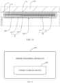
- the power consuming apparatus as illustrated in FIG. 16 in the implementations of the present disclosure includes, but is not limited to, a portable apparatus such as a Bluetooth headset, a mobile phone, a digital device and a tablet computer, and a large-scale apparatus such as an electric motorcycle, an electric vehicle, and an energy storage power station, which will not be limited in the implementations of the present disclosure.
- the energy storage device supplies electric energy for the power consuming apparatus.
- the energy storage device includes, but is not limited to, at least one of a traction battery, a fuel cell, a supercapacitor, etc.
- the traction battery includes, but is not limited to, a lithium-ion traction battery, a metal hydride nickel traction battery, a supercapacitor, etc.
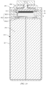
- FIG. 1 shows a schematic structural diagram of an energy storage device 100 provided in an implementation of the present disclosure
- FIG. 2 is an exploded view of the energy storage device 100 in FIG. 1 from a first perspective
- FIG. 3 is an exploded view of the energy storage device 100 in FIG. 2 from a second perspective.
- the energy storage device 100 includes a housing 10, an end cap assembly 20, an electrode assembly 30 and an adapter assembly 40.
- the electrode assembly 30 and the adapter assembly 40 are arranged in the housing 10, and the housing 10 is sealingly and fixedly connected to the end cap assembly 20 to realize the packaging of the electrode assembly 30 and the adapter assembly 40.
- the housing 10 has an opening 101 and a receiving cavity 102 in communication with the opening 101.
- the electrode assembly 30 is received in the receiving cavity 102.
- the receiving cavity 102 is further configured to store an electrolyte solution, so that the electrolyte solution can infiltrate the electrode assembly 30.
- the end cap assembly 20 includes an end cap 201 and a terminal post 202 arranged on a cap plate
- the electrode assembly 30 includes a battery cell 301 and a tab 302 electrically connected to the battery cell 301.
- the terminal post 202 is electrically connected to the tab 302 via the adapter assembly 40.
- One or more battery cells 301 may be included.
- the electrode assembly 30 includes two battery cells 301 arranged side by side in a width direction of the energy storage device 100. It may be noted that the number of battery cells 301 is only for illustration and does not constitute a specific limitation, and the number of battery cells 301 needs to be designed according to the actual product design.
- the energy storage device 100 further includes a lower plastic member 50 connected to the end cap assembly 20.
- the lower plastic member 50 is fixedly connected to the side of the end cap 201 close to the housing 10.
- the lower plastic member 50 is provided with a limiting groove 501 for positioning the adapter assembly 40.
- the bottom of the limiting groove 501 is provided with a limiting boss 502 for abutting against the second connecting portion 13, so that the adapter assembly 40 is evenly stressed during assembling, is positioned reliably, and has improved assembly efficiency and accuracy.
- FIG. 1 shows only a schematic structure of an energy storage device 100 according to an implementation of the present disclosure, and does not constitute a specific limitation on the energy storage device 100.
- the energy storage device 100 may include more or fewer components than those shown in FIG. 1 , or a combination of some components, or different components.
- the energy storage device 100 may further include, but not limited to, a temperature sensor, a battery management system, a connecting harnesses, etc.
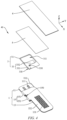
- FIG. 4 is an exploded view of the adapter assembly 40 of the energy storage device 100 in FIG. 3 from a first perspective
- FIG. 5 is an exploded view of the adapter assembly 40 of the energy storage device 100 in FIG. 4 from a second perspective.
- the adapter assembly 40 includes an adapter 1 and a limiting member 3.
- the adapter 1 includes a first connecting portion 11, a second connecting portion 13, and a bendable connecting portion 15 connected between the first connecting portion 11 and the second connecting portion 13.
- the first connecting portion 11 is arranged opposite the second connecting portion 13.
- the limiting member 3 is located between the first connecting portion 11 and the second connecting portion 13 foldable with respect to each other, and is configured to be insulated from the adapter 1.
- the limiting member 3 has a limiting face 310 configured to abut against the bendable connecting portion 15.
- the bendable connecting portion 15 is configured to rotate and bend around the limiting face 310.
- the adapter 1 may be a positive electrode adapter.
- the positive electrode adapter is an aluminum foil or an aluminum alloy foil. Since the material of the aluminum foil or the aluminum alloy foil is relatively soft, the positive electrode adapter is prone to breakage after excessive bending.
- the adapter 1 may also be a negative electrode adapter.
- the negative electrode adapter is a copper foil or a copper alloy foil, and the copper foil or the copper alloy foil is also prone to breakage after excessive bending. Therefore, the adapter assembly 40 provided in the present disclosure is based on adding a limiting member 3 between the first connecting portion 11 and the second connecting portion 13.
- the limiting member 3 can buffer the bendable connecting portion 15, so that the limiting member 3 can absorb and disperse the stress of the bendable connecting portion 15 during bending, so as to improve the structural stress strength of the bendable connecting portion 15 during the bending, and the problem of breakage of the bendable connecting portion 15 due to excessive stress can thus be effectively avoided, thereby prolonging the service life of the bendable connecting portion 15.
- the bendable connecting portion 15 is configured to rotate and bend around the limiting face 310, so that the limiting face 310 functions to guide the bending of the bendable connecting portion 15, and to support the bendable connecting portion 15 during bending, and the adapter 1 is thus easier to bend.
- the limiting member 3 is configured to be insulated from the adapter 1, the problem of short circuit caused by overlapping joint between the first connecting portion 11 and the second connecting portion 13 can be avoided.
- the adapter 1 is configured to be foldable, so that the space can be saved.
- an X-axis direction is defined as a length direction of the energy storage device 100
- a Y-axis direction is defined as a width direction of the energy storage device 100
- a Z-axis direction is defined as a height direction of the energy storage device 100.
- a length direction of the adapter assembly 40 and a length direction of the adapter 1 are directions parallel to the length direction of the energy storage device 100
- a width direction of the adapter assembly 40 and a width direction of the adapter 1 are directions parallel to the width direction of the energy storage device 100
- a height direction of the adapter assembly 40 (i.e. a thickness direction of the adapter assembly 40) and a height direction of the adapter 1 are directions parallel to the height direction of the energy storage device 100.
- the arrow direction of the Z-axis direction is upward
- the direction opposite to the arrow direction of the Z-axis direction is downward.
- the first connecting portion 11 of the adapter assembly 40 is electrically connected to the terminal post 202
- the second connecting portion 13 of the adapter assembly 40 is electrically connected to the tab 302, thereby ensuring the connection area between the first connecting portion 11 and the terminal post 202 and the connection area between the second connecting portion 13 and the tab 302, increasing the connection strength between the first connecting portion 11 and the terminal post 202 and the connection strength between the second connecting portion 13 and the tab 302, and preventing the separation of the first connecting portion 11 from the terminal post 202 and the separation of the second connecting portion 13 from the tab 302 during the use of the energy storage device 100.
- the limiting face 310 is an arc-shaped face, so as to avoid the risk of scratching or hitting the adapter 1 due to the irregular limiting face 310; or to avoid the difficult mounting problem caused by the irregular limiting face 310, thereby further realizing the protection of the bendable connecting portion 15.
- the shape of the limiting face 310 may also be, but not limited to, wave-shaped, polygonal, etc., which will not be specifically limited in the present disclosure.
- the limiting member 3 includes a limiting body 31 and a movable rotary cover 33 rotatably connected to the limiting body 31, the limiting body 31 is configured to abut against the first connecting portion 11, and the movable rotary cover 33 is configured to abut against the second connecting portion 13.
- the bending range of the bendable connecting portion 15 is limited by the bending range of the movable rotary cover 33 relative to the limiting body 31, so as to avoid the breakage of the bendable connecting portion 15 during the bending, and to ensure that the adapter 1 is easy to bend.
- the movable rotary cover 33 is rotatably connected to the limiting body 31, so as to avoid the recessed deformation of a surface of the limiting member 3 under pressure, so that the limiting member 3 has a good pressure resistance capacity, thereby improving the buffering effect of the limiting member 3 on the bendable connecting portion 15.
- the limiting member 3 may only include the limiting body 31, that is, the movable rotary cover 33 may be omitted.
- the first connecting portion 11, the limiting body 31, the movable rotary cover 33 and the second connecting portion 13 are stacked in sequence in the thickness direction of the adapter assembly 40, so that the overall structure of the adapter assembly 40 is more compact, achieving beneficial effects such as saving space, and facilitating the mounting and dismounting of the limiting member 3.
- the limiting body 31 is integrally formed with the movable rotary cover 33.
- the limiting member 3 is configured as a bendable structure.
- the limiting member 3 is configured as an elastic piece that can be bent and unfolded. In this way, the connection strength between the limiting body 31 and the movable rotary cover 33 is increased, the assembly efficiency between the limiting member 3 and the adapter 1 is improved, and the processing and production process of the limiting member 3 is facilitated.
- the movable rotary cover 33 can weaken the squeezing force of the limiting member 3 from the bendable connecting portion 15, so as to avoid the recessed deformation of a surface of the limiting member 3 under pressure, so that the limiting member 3 has a good pressure resistance capacity, thereby improving the buffering effect of the limiting member 3 on the bendable connecting portion 15.
- the limiting body 31 and the movable rotary cover 33 may also be rotatably connected together via a rotating shaft, a hinge, etc., which will not be specifically limited in the present disclosure.
- the first connecting portion 11 includes a first welding area 111.
- the terminal post 202 arranged on the end cap 201 is mainly assembled to the first welding area 111 of the first connecting portion 11 by welding or riveting.
- Welding includes, but is not limited to, resistance spot welding, ultrasonic welding, laser welding and other processes.
- the first connecting portion 11 is assembled to the terminal post 202 by using a laser welding process. It may be noted that the resistance spot welding, laser welding process and ultrasonic welding process are widely used in the art, and will not be described in detail here.
- the limiting body 31 defines a window 311 for exposing the first welding area 111.
- the adapter assembly 40 further includes a first insulating film 5.
- the first insulating film 5 is arranged at the window 311 and shields the window 311. In this way, the first insulating film 5 can prevent the risk of a short circuit caused by the metal chips such as welding slag and rusty slag at the first connecting portion 11 falling into the energy storage device 100, facilitating the improvement of the yield and safety of the energy storage device 100.
- the first insulating film 5 can further avoid the problem of short circuit caused by contact between the first connecting portion 11 and the second connecting portion 13.
- FIG. 6 is a partial exploded view of the adapter assembly 40 of the energy storage device 100 in FIG. 2 .
- the window 311 has a square shape, that is, edge portions of the limiting body 31 for abutting against the first insulating film 5 are formed around the window 311, increasing the contact area between the limiting body 31 and the first insulating film 5, that is, increasing the frictional force between the limiting body 31 and the first insulating film 5, thereby reducing the risk of the first insulating film 5 falling off or displacing, and achieving a high use safety and prolonged service life.
- Side walls of the window 311 and the first insulating film 5 enclose a storage tank 312.
- the storage tank 312 is configured to store the metal chips such as welding slag and rusty slag, so as to avoid scratching the second connecting portion 13 during the movement, and to ensure that the metal chips such as welding slag and rusty slag would not overflow from the first insulating film 5.
- Such a design saves the use cost for a user, the energy storage device 100 has a high specific energy, the structure of the energy storage device 100 is compact, and the mounting space is saved.
- the window 311 may also be C-shaped, U-shaped, etc.
- the shape of the window 311 may be designed according to the shape of the first welding area 111, which will not be specifically limited in the present disclosure.
- the limiting body 31 of the limiting member 3, the edges and corners of the movable rotary cover 33 and the corners of the window 311 are rounded, so as to prevent the limiting member 3 from damaging the first insulating film 5.
- the length of the first insulating film 5 is greater than that of the first welding area 111, and the width of the first insulating film 5 is greater than that of the first welding area 111, so as to ensure that the first insulating film 5 can block the slag such as welding slag and rusty debris at the first welding area 111.
- the first connecting portion 11 further includes a first non-welding area 112 arranged around the outside of the first welding area 111.
- the first insulating film 5 covers the first welding area 111 and the first non-welding area 112, so as to better realize the insulation protection between the first connecting portion 11 and the second connecting portion 13, and ensure that the first insulating film 5 can still shield the first welding area 111 after being displaced by a predetermined distance, to block the slag such as welding slag and rusty debris, improving the safety performance of the energy storage device 100.
- the length of the first insulating film 5 is equal to that of the first welding area 111, and/or the width of the first insulating film 5 is equal to that of the first welding area 111, thereby saving the production cost.
- the first insulating film 5 may also only cover the first welding area 111.
- the material of the first insulating film 5 includes, but is not limited to, one or a combination of polypropylene (PP), polyphenylene sulfide (PPS), polyethylene terephthalate (PET), polyimide (PI), polystyrene (PS), cast polypropylene film (CPP), polyethylene naphthalate two formicacid glycol ester (PEN), polyvinyl chloride (PVC), polyether-ether-ketone (PEEK), polyethersulfone resin (PES), polyphenylene sulfone resins (PPSM), and polyethylene (PE).
- the first insulating film 5 is a PET film.
- the PET film is a glossy plastic film with high-quality physical properties, high rigidity, strength and ductility, and excellent puncture resistance, abrasion resistance, heat resistance and ultra-low temperature resistance, chemical resistance, wear resistance, sealing and fragrance retention.
- the first insulating film 5 may instead be made of other materials such as PPS, PE and PVC according to actual requirements.
- the number of first insulating films 5 may be selected to a single layer or multiple layers.
- the multiple layers of first insulating films 5 of multiple layers are, for example, two layers, three layers, four layers or more. It may be noted that the number of first insulating films 5 is only for illustration and does not constitute a specific limitation.
- the first insulating film 5 has a thickness of 0.05-0.5 mm. The thickness of the first insulating film 5 needs to be determined according to the actual product design. If the first insulating film 5 is too thin, it may be easily damaged, but if the first insulating film 5 is too thick, it will increase the weight of the energy storage device 100 and reduce the energy density of the energy storage device 100.
- the first insulating film 5 is clamped between the limiting body 31 and the movable rotary cover 33, thereby reducing the displacement or detachment of the first insulating film 5 during the movement of the energy storage device 100, and improving the assembly efficiency of the first insulating film 5.
- the limiting body 31 is fixed to the first connecting portion 11 via the first insulating film 5.
- the first insulating film 5 has viscosity, that is, the limiting body 31 is bonded to the first connecting portion 11 via the first insulating film 5, such that the limiting body 31 is clamped between the first insulating film 5 and the first connecting portion 11.
- connection strength between the first insulating film 5 and the first connecting portion 11 is increased to further reduce the displacement or detachment of the first insulating film 5 during the movement of the energy storage device 100.
- the position of the limiting member 3 is defined, so as to ensure that the bendable connecting portion 15 can be rotated and bent around the limiting face 310 of the limiting member 3, and to improve the assembly efficiency of the limiting body 31.
- the first insulating film 5 is provided at the first welding area 111 to carry out insulation protection on the first welding area 111 of the first connecting portion 11, and avoid product explosion and other safety accidents caused by a potential hazard of internal short circuit in the energy storage device 100 during the manufacturing and movement.
- the first insulating film 5 is attached to the first non-welding area 112 of the first connecting portion 11.
- the first insulating film 5 is attached to the first welding area 111 of the first connecting portion 11.
- the first insulating film 5 is attached to the first welding area 111 and the first non-welding area 112 of the first connecting portion 11.
- the first insulating film 5 may also be attached to a side face of the limiting body 31 that is close to the movable rotary cover 33, so as to further enhance the connection strength between the first insulating film 5 and the limiting member 3 and between the first insulating film and the first connecting portion 11, to reduce the displacement or detachment of the first insulating film 5 during the movement of the energy storage device 100.
- the first insulating film 5 may not have viscosity, that is, the first insulating film 5 is clamped between the limiting body 31 and the movable rotary cover 33, thereby simplifying the assembly efficiency and saving costs.
- the limiting body 31 is fixed to the first connecting portion 11, so as to further increase the connection strength between the limiting member 3 and the adapter 1, to better fix the relative position of the limiting member 3, thereby avoiding the displacement of the limiting member 3 and the resulting abnormal bending of the bendable connecting portion 15 and displacement or detachment of the first insulating film 5.
- the limiting body 31 and the first connecting portion 11 may be fixedly connected together by means of adhesive bonding, that is, an adhesive layer is provided between the limiting body 31 and the first connecting portion 11, so that the adhesive layer can be further used for buffering the stress of the bendable connecting portion 15, improving the bending efficiency and success rate, and simplifying the overall structure of the adapter assembly 40.
- the limiting body 31 and the first connecting portion 11 may also be fixedly connected together by, but not limited to, thermal fusion, binding, mechanical connection, laser welding, ultrasonic welding, etc.
- the movable rotary cover 33 is arranged movably relative to the second connecting portion 13, so as to facilitate the assembly and disassembly of the limiting member 3.
- the movable rotary cover 33 may also be fixed to the second connecting portion 13.
- the limiting body 31 may be arranged movably relative to the first connecting portion 11.
- at least one of the movable rotary cover 33 and the limiting body 31 is arranged fixedly relative to the adapter 1, so as to avoid the problem of affecting the bending of the adapter 1 due to the displacement of the limiting member 3.
- the adapter assembly 40 further includes a second insulating film 6, with the second insulating film 6 being clamped between the first insulating film 5 and the movable rotary cover 33.
- the second insulating film 6 can prevent the risk of a short circuit caused by the metal chips such as welding slag and rusty slag at the second connecting portion 13 falling into the energy storage device 100, facilitating the improvement of the yield and safety of the energy storage device 100.
- the second insulating film 6 can further avoid the problem of short circuit caused by contact between the first connecting portion 11 and the second connecting portion 13.
- the second connecting portion 13 includes a second welding area 131.
- the movable rotary cover 33 defines a notch 330 at a position corresponding to the second welding area 131 to expose the second insulating film 6.
- the second insulating film 6 can cover the entire second welding area 131, further avoiding the risk of a short circuit caused by the metal chips such as welding slag and rusty slag at the second connecting portion 13 falling into the energy storage device 100, and improving the yield and safety of the energy storage device 100.
- the notch 330 is defined at the end of the movable rotary cover 33 facing away from the limiting body 31, so as to ensure the connection strength between the movable rotary cover 33 and the limiting body 31 and prevent the movable rotary cover 33 from breaking during rotating.
- the second connecting portion 13 further includes a second non-welding area 132 arranged around the outside of the second welding area 131.
- the second insulating film 6 covers the second welding area 131 and the second non-welding area 132, so as to better realize the insulation protection between the first connecting portion 11 and the second connecting portion 13, and ensure that the second insulating film 6 can still shield the second welding area 131 after being displaced by a predetermined distance, to block the slag such as welding slag and rusty debris, improving the safety performance of the energy storage device 100.
- the length of the second insulating film 6 is equal to that of the second welding area 131, and/or the width of the second insulating film 6 is equal to that of the second welding area 131, thereby saving the production cost.
- the second insulating film 6 may also only cover the second welding area 131.
- FIG. 7 is a cross-sectional view of the second insulating film 6 of the adapter assembly 40 in FIG. 5 along line A-A.
- the second insulating film 6 includes a first film body 61 attached to a first insulating film 5 and a second film body 62 foldable with respect to and connected to the first film body 61, with the second film body 62 facing the second connecting portion 13, so as to better fix the relative positions of the first insulating film 5 and the second insulating film 6.
- the first film body 61 may be fixed to the first insulating film 5 by means of bonding.
- the second film body 62 may also be fixed to the movable rotary cover 33 and/or the second connecting portion 13 by means of bonding, so as to further avoid displacement of the first insulating film 5 and the second insulating film 6.
- the second insulating film 6 may also be configured as a single-layer film.
- the second insulating film 6 may be omitted, the first insulating film 5 covers both the second welding area 131 and the first welding area 111, and the first insulating film 5 is configured as a double-layer film, with one layer of insulating film covering the first welding area 111, and the other layer of insulating film covering the second welding area 131.
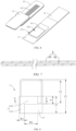
- FIG. 8 is an enlarged view of the limiting member 3 of the adapter assembly 40 in FIG. 4 ; and FIG. 9 is a cross-sectional view of the limiting member 3 of the adapter assembly 40 in FIG. 8 along line B-B.
- the limiting member 3 has a thickness H of 0.03 mm-5 mm in the thickness direction of the adapter assembly 40, that is, the overall thickness of the limiting member 3 is 0.03 mm-5 mm. In this way, stress fatigue or even breakage of the bendable connecting portion 15 of the adapter 1 is avoided during the bending, and the reliability of use of the adapter 1 is improved.
- the space occupied by the limiting member 3 is reduced in the thickness direction of the adapter assembly 40, effectively reducing the thickness of the adapter assembly 40, and further adapting to the market demand for the miniaturization of the adapter assembly 40.
- the radius of curvature of the bendable connecting portion 15 increases as the thickness H of the limiting member 3 in the thickness direction of the adapter assembly 40 increases. If the thickness H of the limiting member 3 in the thickness direction of the adapter assembly 40 is too small, the radius of curvature of the bendable connecting portion 15 is small, leading to the problem of breakage of the bendable connecting portion 15 during the bending. If the thickness H of the limiting member 3 in the thickness direction of the adapter assembly 40 is too large, the radius of curvature of the bendable connecting portion 15 is large, increasing the weight of the energy storage device 100, increasing the occupation of the internal space of the energy storage device 100 by the limiting member 3, and reducing the energy density of the energy storage device 100.
- the thickness H of the limiting member 3 in the thickness direction of the adapter assembly 40 is 2 mm, so as to better balance the overall thickness of the limiting member 3 and the radius of curvature of the bendable connecting portion 15.
- the thickness H of the limiting member 3 in the thickness direction of the adapter assembly 40 is 0.3 mm, 0.05 mm, 0.07 mm, 1 mm, 1.5 mm, 2 mm, 2.5 mm, 3 mm, 3.5 mm, 4 mm, 4.5 mm, 5 mm, and so on. It may be noted that the dimension of the thickness H of the limiting member 3 is only for illustration and does not constitute a specific limitation, and the thickness H of the limiting member 3 needs to be designed according to the actual product design.
- a ratio of a length C1 of the window 311 to a length C2 of the limiting body 31 is 0.2-0.5, so as to prevent the limiting member 3 from being misaligned with the first connecting portion 11 due to the displacement caused by vibration during transportation of the energy storage device 100, thereby effectively blocking the welding slag of the first connecting portion 11 and improving the safety of the energy storage device 100.
- the ratio of the length C1 of the window 311 to the length C2 of the limiting body 31 is 0.2, 0.25, 0.3, 0.35, 0.4, 0.45, 0.5, and so on.
- the length C1 of the window 311 is 8 mm
- the length C2 of the limiting body 31 is 26 mm
- the ratio of the length C1 of the window 311 to the length C2 of the limiting body 31 is 0.3. It may be noted that the dimensions of the length C1 of the window 311 and the length C2 of the limiting body 31 are only for illustration and do not constitute a specific limitation, and the length C1 of the window 311 and the length C2 of the limiting body 31 need to be designed according to the actual product design.
- the movable rotary cover 33 may have an L-shaped structure as a whole.
- the movable rotary cover 33 includes a fixing portion 331 connected to the limiting body 31, and an extension portion 332 connected to the side of the fixing portion 331 facing away from the limiting body 31.
- a length C3 of the fixing portion 331 is equal to or greater than a length C4 of the extension portion 332, so as to ensure the connection strength between the fixing portion 331 and the limiting body 31.
- the movable rotary cover 33 may also have a C-shaped structure or a U-shaped structure as a whole, so as to further increase the retaining area between the movable rotary cover 33 and the second insulating film 6, thereby reducing the displacement or detachment of the first insulating film 5 during the movement of the energy storage device 100.
- the corners of the notch 330 are rounded, so as to prevent the limiting member 3 from damaging the second insulating film 6.
- the fixing portion 331 has a width W1 of approximately 2 mm-6 mm
- the extension portion 332 has a width W2 of 5 mm-10 mm.
- the width W1 of the fixing portion 331 is 2 mm, 3 mm, 4 mm, 5 mm, 6 mm, and so on
- the width W2 of the extension portion 332 is 5 mm, 6 mm, 7 mm, 8 mm, 9 mm, 10 mm, and so on.
- width W1 of the fixing portion 331 and the width W2 of the extension portion 332 are only for illustration and do not constitute a specific limitation, and the width W1 of the fixing portion 331 and the width W2 of the extension portion 332 need to be designed according to the actual product design.
- the material of the first insulating film 5 is applicable to the material of the second insulating film 6, and reference is made to the description of the above implementations for specific details, which will not be repeated here.
- the material of the second insulating film 6 may be different from that of the first insulating film 5; or may be the same as that of the first insulating film 5.
- the color of the first insulating film 5 is different from the color of the second insulating film 6, so as to facilitate identification, improving the assembly efficiency and accuracy, and facilitating the determination of whether the first insulating film 5 and the second insulating film 6 are missing, displaced, detached, etc. during machine inspection or manual inspection.
- the first insulating film 5 is a blue insulating film
- the second insulating film 6 is a green insulating film.
- the colors of the first insulating film 5 and the second insulating film 6 may also be the same.
- the colors of the first insulating film 5 and the second insulating film 6 are other colors, which will not be specifically limited in the present disclosure.
- At least one of the first connecting portion 11 and the second connecting portion 13 is provided with an anchor member for anchoring the first insulating film 5 and the second insulating film 6, thereby further avoiding the displacement or detachment of the first insulating film 5 and the second insulating film 6.
- the anchor member may be configured as a hook structure or a protrusion structure provided on the first connecting portion 11 and the second connecting portion 13, and the first insulating film 5 and the second insulating film 6 are each provided with a snap hole for cooperating with the hook structure or the protrusion structure.
- An orthographic projection of the notch 330 on the first insulating film 5 is spaced apart from an orthographic projection of the window 311 on the first insulating film 5, that is, the extension portion 332 of the movable rotary cover 33 and the limiting body 31 stop against each other. In this way, the risk of a short circuit caused by contact between the first connecting portion 11 and the second connecting portion 13 is avoided. Moreover; the risk of a short circuit caused by the contact between the slag such as welding slag and rusty debris and the first connecting portion 11 or the second connecting portion 13 through the window 311 and the notch 330 is avoided. Furthermore, the occurrence of displacement caused by the movable rotary cover 33 pushing the first insulating film 5 and the second insulating film 6 is avoided.
- the limiting member 3 is arranged at a position corresponding to the bendable connecting portion 15, so as to ensure that the bendable connecting portion 15 can be bent smoothly, improving the mass production yield of the product.
- the limiting member 3 is configured to abut against the bendable connecting portion 15, so as to ensure that the bendable connecting portion 15 can be rotated and bent around the limiting member 3.
- the limiting member 3 is spaced apart from the bendable connecting portion 15 by a predetermined distance, so as to provide a space for the deformation of the bendable connecting portion 15.
- the predetermined distance is approximately 1 mm-3 mm, so as to ensure that the bendable connecting portion 15 can be rotated and bent around the limiting member 3.
- the limiting member 3 is arranged in an area where the first connecting portion 11 and the second connecting portion 13 overlap, so as to ensure that the first connecting portion 11 and the second connecting portion 13 can drive the limiting member 3 to press the first insulating film 5 and the second insulating film 6, thereby avoiding the problem of displacement of the first insulating film 5 and the second insulating film 6.
- the limiting member 3 is of a plastic structure.
- the plastic structure is, for example, but not limited to, PET sheet, PE sheet, PS sheet and other sheets.
- the insulating effect of the limiting member 3 is realized.
- the buffering effect of the limiting member 3 is improved.
- the production cost is reduced.
- the frictional force between the first insulating film 5 and the second insulating film 6 is increased, avoiding the displacement of the first insulating film 5 and the second insulating film 6.
- the limiting member 3 may also be of other structures having an insulating effect, such as, but not limited to, asbestos or mica.
- the limiting member 3 is configured as a sheet-like structure, so as to facilitate the rotating and folding of the movable rotary cover 33 with respect to the limiting body 31, and reduce the space occupied by the limiting member 3 in the adapter assembly 40, thereby saving the production cost. Moreover, it is ensured that the movable rotary cover 33 has a flat surface after being folded with respect to the limiting body 31, so as to better press the first insulating film 5 and the second insulating film 6.
- the bendable connecting portion 15 defines a through hole 150 to form, on two opposite sides of the through hole 150, a first fuse portion 151 and a second fuse portion 152 connected to the first connecting portion 11 and the second connecting portion 13, and the limiting member 3 shields at least a part of the through hole 150.
- the limiting member 3 can increase the insulation of the first connecting portion 11 and the second connecting portion 13 on two sides of the first fuse portion 151 and the second fuse portion 152, thereby further increasing the arc extinguishing effect. Secondly, it is ensured that after the displacement of the first insulating film 5 and the second insulating film 6, the limiting member 3 can still isolate the first connecting portion 11 from the second connecting portion 13 to prevent a contact short circuit.
- the arrangement of the limiting member 3 can avoid the problem of short circuit caused by a further overlapping joint between the first connecting portion 11 and the second connecting portion 13. Fourthly, the problem of potential safety hazard caused by the metal chips entering the interior of the energy storage device 100 through the through hole 150 is avoided.
- the through hole 150 is a right-angled quadrilateral hole, such as a square hole or a rectangular hole.
- the rectangular hole is a rectangular hole with an ellipse.
- the through hole 150 may also be a diamond hole, a rectangular hole, a polygonal hole, an elliptic hole, a waist hole, a circular hole, etc., which will not be specifically limited in the present disclosure.
- FIG. 10 is a schematic view of the adapter 1 of the adapter assembly 40 in FIG. 4 in an unfolded state.
- the through hole 150 has a first linear section 1501, a first corner section 1502, a second corner section 1503 and a second linear section 1504.
- the first linear section 1501 is connected to the first corner section 1502 and adjacent to the first fuse portion 151
- the second linear section 1504 is connected to the second corner section 1503 and adjacent to the second fuse portion 152
- the first corner section 1502 and the second corner section 1503 are rounded, so as to avoid the problem of damage to the tab 302 caused by the adapter 1.
- the edges and corners of the first connecting portion 11, the second connecting portion 13 and the bendable connecting portion 15 are all rounded, so as to further avoid the problem of damage to the tab 302 caused by the adapter 1.
- the unfolded state of the adapter 1 refers to a state in which the bendable connecting portion 15 of the adapter 1 is not bent.
- the first connecting portion 11, the second connecting portion 13 and the bendable connecting portion 15 are arranged coplanarly.
- the unfolded state of the adapter 1 is only for describing the accuracy of the through hole 150, and is not the product use state of the energy storage device 100.
- the bendable connecting portion 15 of the adapter 1 is bent, and the first connecting portion 11 and the second connecting portion 13 are arranged opposite each other.
- the distance between the first linear section 1501 and the end of the first fuse portion 151 away from the first linear section 1501 is a first distance D 1
- the distance between the end of the first corner section 1502 away from the first linear section 1501 and the end of the first fuse portion 151 away from the first corner section 1502 is a second distance D2, where the first distance D1 is less than the second distance D2.
- the distance between the second linear section 1504 and the end of the second fuse portion 152 away from the second linear section 1504 is a third distance D3, and the distance between the end of the second corner section 1503 away from the second linear section 1504 and the end of the second fuse portion 152 away from the second corner section 1503 is a fourth distance D4, where the third distance D3 is less than the fourth distance D4.
- the bendable connecting portion 15 is provided with the through hole 150, so as to fuse the first fuse portion 151 and the second fuse portion 152 to disconnect the circuit, improving the use safety and prolonging the service life.
- the first corner section 1502 and the second corner section 1503 of the through hole 150 are both rounded, so as to prevent the adapter 1 from scratching the tab 302, improving the production yield.
- the fusing position of the adapter 1 is closer to a mechanical fatigue area of the bendable connecting portion 15, and the fusing effect is thus easier to form, improving the safety of the energy storage device 100.
- a fusing direction F 11 of the first fuse portion 151 and a fusing direction F12 of the second fuse portion 152 are perpendicular to a bending direction F2 of the bendable connecting portion 15, so as to ensure that the fusing of the first fuse portion 151 and the second fuse portion 152 is easier to form and to facilitate the bending of the adapter 1.
- the fusing direction F 11 of the first fuse portion 151 and the fusing direction F12 of the second fuse portion 152 refer to the direction perpendicular to the current direction of the adapter 1
- the fusing direction F11 of the first fuse portion 151 refers to the direction from the first linear section 1501 to the end of the first fuse portion 151 away from the first linear section 1501
- the fusing direction F12 of the second fuse portion 152 refers to the direction from the second linear section 1504 to the end of the second fuse portion 152 away from the second linear section 1504.
- the current direction of the adapter 1 is parallel to the bending direction F2 of the bendable connecting portion 15.
- the ratio of the first distance D 1 to the second distance D2 is 0.7-0.95, and the ratio of the third distance D3 to the fourth distance D4 is 0.7-0.95, so as to ensure the fusing reliability of the first fuse portion 151 and the second fuse portion 152, while ensuring that the adapter 1 has the characteristics of high strength and not easy to break.
- the ratio of the first distance D1 to the second distance D2 and the ratio of the third distance D3 to the fourth distance D4 are 0.7, 0.73, 0.75, 0.77, 0.8, 0.85, 0.88, 0.9, 0.93 or 0.95, and so on.
- the first distance D1 is 7 mm
- the second distance D2 is 8 mm
- the ratio of the first distance D1 to the second distance D2 is 0.88.
- the through hole 150 further includes a third linear section 1505 and a fourth linear section 1506 each connected to the first corner section 1502 and the second corner section 1503, and the first linear section 1501, the two first corner sections 1502, the two second corner sections 1503, the second linear section 1504, the third linear section 1505 and the fourth linear section 1506 enclose the through hole 150. Therefore, a punching die made for such a manufacturing has a simple structure, and it is easier to open and close the die. At the same time, the bending length required for the bending position of the bendable connecting portion 15 is reduced by means of the through hole 150, which is more conducive to bending and forming.
- the lengths of the first linear section 1501 and the second linear section 1504 are equal and are the first length L1, the distance between the third linear section 1505 and the fourth linear section 1506 is a fifth distance D5, and the ratio of the first length L1 to the fifth distance D5 is 3/7-9/10, so as to ensure that the bendable mechanical fatigue zone of the bendable connecting portion 15 is highly coincident with the positions formed by the fusing of the first fuse portion 151 and the second fuse portion 152, and then the fusing of the first fuse portion 151 and the second fuse portion 152 occurs more easily.
- the ratio of the first length L1 to the fifth distance D5 may be, but not limited to, 0.4, 0.5, 0.6, 0.7, 0.8 or 0.9, and so on.
- the lengths of the third linear section 1505 and the fourth linear section 1506 are equal and are the second length L2
- the distance between the first linear section 1501 and the second linear section 1504 is a sixth distance D6
- the ratio of the second length L2 to the sixth distance D6 is 0.4-0.9, so as to ensure the fusing reliability of the first fuse portion 151 and the second fuse portion 152, while ensuring that the adapter 1 has the characteristics of high strength and not easy to break.
- the ratio of the second length L2 to the sixth distance D6 may be, but not limited to, 0.4, 0.5, 0.6, 0.7, 0.8 or 0.9, and so on.
- the radii of the rounded corners of the first corner section 1502 and the second corner section 1503 are both 0.5 mm-1.5 mm, so as to avoid the problem of breakage of the first fuse portion 151 and the second fuse portion 152 during the bending.
- the radii of the rounded corners of the first corner section 1502 and the second corner section 1503 are 0.5 mm, 1.0 mm, 1.5 mm, and so on. It may be noted that the radii of the rounded corners of the first corner section 1502 and the second corner section 1503 are only for illustration and does not constitute a specific limitation, and the radii of the rounded corners of the first corner section 1502 and the second corner section 1503 need to be designed according to the actual product design.
- the distance between the end of the first fuse portion 151 away from the first linear section 1501 and the end of the second fuse portion 152 away from the second linear section 1504 is a seventh distance D7
- the ratio of the sixth distance D6 to the seventh distance D7 is 0.15-0.25, so as to ensure that the fusing of the first fuse portion 151 and the second fuse portion 152 occurs more easily, while avoiding stress fatigue or even breakage of the first fuse portion 151 and the second fuse portion 152 of the adapter 1 during the bending, improving the reliability of use of the adapter 1.
- the ratio of the sixth distance D6 to the seventh distance D7 may be, but not limited to, 0.15, 0.2 or 0.25, and so on.
- the sixth distance D6 is 3 mm
- the seventh distance D7 is 18 mm.
- the ratio of the sixth distance D6 to the seventh distance D7 is 0.17.
- the sixth distance D6 of the through hole 150 gradually decreases from the middle of the through hole 150 toward the two sides in the current direction of the adapter 1 (that is, the direction from the third linear section 1505 to the fourth linear section 1506), so as to ensure that the first fuse portion 151 and the second fuse portion 152 can be fused in the middle of the through hole 150, while ensuring the connection strength between two side edges of the first fuse portion 151 and the second fuse portion 152 and the first connecting portion 11 and the second connecting portion 13, further avoiding the breakage of the adapter 1 during the rotating and bending process.
- the first connecting portion 11, the limiting member 3 and the second connecting portion 13 are stacked in the thickness direction of the adapter 1.
- the overall structure of the adapter 1 is made more compact and saves space.
- the first connecting portion 11 and the second connecting portion 13 are spaced apart by the limiting member 3 in the thickness direction of the adapter 1, so as to avoid the problem of short circuit between the first connecting portion 11 and the second connecting portion 13, and the limiting member 3 provides a buffering effect between the first connecting portion 11 and the second connecting portion 13, and enhances the structural strength of the bendable connecting portion 15, thereby avoiding the problem of wrinkling or breakage of the bendable connecting portion 15 after being bent.
- the first connecting portion 11 includes a first welding area 111
- the second connecting portion 13 includes a second welding area 131.
- Orthographic projections of the first welding area 111 and the second welding area 131 on the first connecting portion 11 are spaced apart from each other, thereby further avoiding the risk of a short circuit caused by contact between the first connecting portion 11 and the second connecting portion 13.
- the orthographic projections of the first welding area 111 and the second welding area 131 on the first connecting portion 11 are arranged adjacent to each other or at least partially overlap with each other, shortening the length of the adapter 1, thereby saving the space and lightening the weight, reducing the material consumption of the conductive connecting member, and save the cost.
- the bendable connecting portion 15 includes, but is not limited to, a C-shaped structure, a U-shaped structure, a V-shaped structure or a wave-shaped structure, so as to ensure that the first fuse portion 151 and the second fuse portion 152 can be bent smoothly, improving the mass production yield of the product.
- the first fuse portion 151 and the second fuse portion 152 are configured as a C-shaped structure, thereby reducing local bending of the first fuse portion 151 and the second fuse portion 152 and reducing bending fatigue, preventing the breakage of the first fuse portion 151 and the second fuse portion 152, and reducing the space occupied by the bent first fuse portion 151 and second fuse portion 152 in the width direction of the adapter 1.
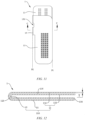
- FIG. 11 is a top view of the adapter 1 of the adapter assembly 40 in FIG. 2 ; and FIG. 12 is a cross-sectional view of the adapter 1 of the adapter assembly 40 in FIG. 11 along line C-C.
- the adapter 1 is folded in half along a first half-folding axis P1 to form two layers of adapter main bodies 110, and a gap 120 is formed between the two layers of adapter main bodies 110. In this way, the breakage of the adapter 1 at the first half-folding axis P1 is avoided.
- the gap 120 may be used as a passage for allowing the tab 302 to be inserted, and may provide a stress release space for the adapter main bodies 110 to bend again, so as to improve the breakage resistance of the adapter 1. It can be understood that if the gap 120 is too large, it is not conducive to folding the two layers of adapter main body 110 in half; and if the gap 120 is too small, the adapter 1 is likely to break when it is bent along the first half-folding axis P1, and it is not conducive to the mounting of the tab 302 and it is likely to damage the tab 302.
- the gap 120 is approximately 0.3 mm-3 mm, so as to ensure smooth half-folding of the two layers of adapter main bodies 110, and to facilitate the mounting of the tab 302 and protect the tab 302 from damage.
- the gap 120 is 0.3 mm, 0.5 mm, 0.7 mm, 1 mm, 1.5 mm, 2 mm, 2.5 mm, 3 mm, and so on. It may be noted that the size of the gap 120 is only for illustration and does not constitute a specific limitation, and the gap 120 needs to be designed according to the actual product design.
- An arc-shaped structure 130 of the adapter 1 is formed at the first half-folding axis P1, so as to further avoid the problem of breakage of the adapter 1 at the first half-folding axis P1, and to facilitate the bending process and improve the assembly efficiency of the tab 302.
- the adapter 1 is folded in half along the first half-folding axis P1 by 180 degrees, so as to ensure that surfaces of the adapter main bodies 110 are flat and are in the form of a stacked structure, thereby ensuring that the two layers of adapter main bodies 110 are easier to bend, and can absorb and disperse the stress during bending.
- the adapter 1 is configured to be foldable, so that the space can be saved and the overall thickness of the adapter 1 can be increased.
- the two layers of adapter main bodies 110 are folded in half along a second half-folding axis P2 to form the first connecting portion 11, the second connecting portion 13 and the bendable connecting portion 15.
- the first half-folding axis P1 is parallel to the second half-folding axis P2.
- the two layers of adapter main bodies 110 serve as a thickened anti-bending layers, which can improve the structural strength of the first fuse portion 151 and the second fuse portion 152, and reduce the damage to a wire caused by an excessive bending angle.
- problems such as abnormal bending and large space occupation caused by the intersection of the first half-folding axis P1 and the second half-folding axis P2 are avoided, facilitating the processing and reducing the production scrap rate.
- the adapter 1 as a whole is folded in half along the first half-folding axis P1 and then bent along the second half-folding axis P2, facilitating the bending process, realizing the standardization of the bending process and improving the processing accuracy.
- the two layers of adapter main bodies 110 are folded in half along the second half-folding axis P2 by 180 degrees, so as to ensure that the surfaces of the first connecting portion 11 and the second connecting portion 13 are flat, facilitating the respective welding to the terminal post 202 and the tab 302, thereby improving the welding quality and saving the space.
- the gap 120 includes an insertion space 135 for allowing the tab 302 to be inserted.
- the adapter main bodies 110 of the second connecting portion 13 include a first connecting plate 133 and a second connecting plate 134, and the insertion space 135 is formed between the first connecting plate 133 and the second connecting plate 134, thereby enabling the second connecting portion 13 to enclose the tab 302, so as to prevent the tab 302 from being damaged and improve the stability of the tab 302.
- an electrical connection between the tab 302 and the second connecting portion 13 is realized by welding, thereby improving the stability and reliability of the connection between the tab 302 and the second connecting portion 13.
- punching is a stamping process that uses a punching die to separate part of a material of a workpiece from the other part of the material.
- the adapter 1 is generally formed by punching a sheet-like plate, that is, the workpiece includes a punched part to be punched out and the adapter 1 left after punching.
- the adapter 1 will have burrs formed at edges of the adapter 1 in the punching process. It may be noted that the orientation of the burrs is the same as the punching direction of the adapter 1.
- the punching direction of the adapter 1 is approximately perpendicular to the extension plane in which the workpiece lies, that is, the punched section of the workpiece is perpendicular to the extension plane in which the workpiece lies.
- the first connecting plate 133 is closer to the first connecting portion 11 than the second connecting plate 134
- the second connecting plate 134 is farther away from the first connecting portion 11 than the first connecting plate 133
- the punching direction of the first connecting plate 133 is directed to the first connecting portion 11 and is opposite to that of the second connecting plate 134, so as to avoid the risk of the tab 302 being broken due to the burrs on the punched edges scratching the tab 302.
- the punching direction of the first connecting plate 133 faces upward
- the punching direction of the second connecting plate 134 faces downward, so that the burrs at the edges of the first connecting plate 133 and the burrs at the edges of the second connecting plate 134 extend toward the side away from the insertion space 135, thereby greatly reducing the risk of the burrs scratching the tab 302 and improving the production yield.
- the adapter 1 may include one metal foil, so as to save the cost, reduce the weight, and facilitate the bending of the adapter 1.
- the adapter 1 may also include multiple metal foils. All the metal foils are stacked and folded in half along the first half-folding axis P1 to form two layers of adapter main bodies 110. All the metal foils are integrated into an integral structure. Therefore, by configuring the adapter 1 as a multi-layer stacked structure, the thickness of the stacked structure is increased so as to better absorb and disperse the stress during bending, thereby avoiding the problem of breakage of the adapter 1 during the bending.
- the integration of all the metal foils into an integral structure ensures that the tab 302 is not damaged, and can be smoothly inserted between the two layers of adapter main bodies 110.
- a circuit between the first connecting portion 11 and the second connecting portion 13 can be disconnected quickly, and the limiting member 3 can further prevent the outermost layer of metal foil from creeping, which is likely to lead to the problem of overlapping joint between the first connecting portion 11 and the second connecting portion 13.
- the metal foil may be, but not limited to, an aluminum foil, a copper foil, etc.
- the metal foil has a thickness T of 0.02 mm-0.4 mm, so as to enhance the overall structural strength of the adapter 1 and facilitate the bending process.
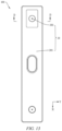
- FIG. 13 is a top view of the energy storage device 100 in FIG. 1 ;
- FIG. 14 is a cross-sectional view of the energy storage device in FIG. 13 along line D-D; and
- FIG. 15 is an enlarged view of part I of the energy storage device in FIG. 14 .
- the rotating and folding of the first connecting portion 11 with respect to the second connecting portion 13 can drive the movable rotary cover 33 to rotate and bend relative to the limiting body 31, such that the first insulating film 5 and the second insulating film 6 are pressed between the limiting body 31 and the movable rotary cover 33.
- the displacement of the first insulating film 5 and the second insulating film 6 is avoided.
- the thickness of the limiting member 3 in the thickness direction of the adapter assembly 40 is increased to better absorb and disperse the stress during bending, so as to avoid the problem of breakage of the adapter 1 during the bending.
- the tab 302 extends into the limiting groove 501 of the lower plastic member 50, and is received in the insertion space 135 formed between the first connecting plate 133 and the second connecting plate 134, thereby enabling the tab 302 to be clamped by the first connecting plate 133 and the second connecting plate 134.
- the tab 302 includes a first connecting section 3021 connected to the battery cell 301, a second connecting section 3022 connected to the second connecting portion 13, and a third connecting section 3023 connected to the first connecting section 3021 and the second connecting section 3022.
- the first connecting section 3021 and the second connecting section 3022 are spaced apart from each other, and are both bent in the same direction relative to the third connecting section 3023, so that the degree of bending of the tab 302 can be improved, and the internal space of the energy storage device 100 can be effectively saved.
- the tab 302 is prevented from coming into contact with the adapter 1 during bending, thereby preventing a short circuit in the energy storage device 100 and increasing the energy density of the energy storage device 100.
Landscapes
- Chemical & Material Sciences (AREA)
- Chemical Kinetics & Catalysis (AREA)
- Electrochemistry (AREA)
- General Chemical & Material Sciences (AREA)
- Engineering & Computer Science (AREA)
- Manufacturing & Machinery (AREA)
- Connection Of Batteries Or Terminals (AREA)
- Details Of Connecting Devices For Male And Female Coupling (AREA)
- Battery Mounting, Suspending (AREA)
Abstract
Description
- The present disclosure relates to the technical field of energy storage, and in particular to an adapter assembly, an energy storage device and a power consuming apparatus.
- Energy storage devices have high requirements for their performance. In the related art, the energy storage device includes a terminal post arranged at an electrode assembly and a tab arranged at a top cover, and it is necessary for the tab to be connected to and electrically conducted with the terminal post via an adapter. Specifically, during assembling of the energy storage device, two side portions of the adapter are respectively connected to the terminal post and the tab, and then the two side portions of the adapter are folded with respect to each other, to enable the adapter to be received between the electrode assembly and the top cover. However, how to prolong the service life of the energy storage device has become an urgent problem to be solved.
- In view of this, an objective of the present disclosure is to provide an adapter assembly, an energy storage device and a power consuming apparatus, so as to solve the problem of low service life of the energy storage device.
- In a first aspect, an implementation of the present disclosure provides an adapter assembly, including: an adapter, including a first connecting portion, a second connecting portion, and a bendable connecting portion connected between the first connecting portion and the second connecting portion, the first connecting portion being arranged opposite the second connecting portion; and a limiting member, which is located between the first connecting portion and the second connecting portion foldable with respect to each other, and which is configured to be insulated from the adapter, where the limiting member has a limiting face configured to abut against the bendable connecting portion, and the bendable connecting portion is configured to rotate and bend around the limiting face.
- The adapter assembly provided in the implementation of the present disclosure is based on adding a limiting member between the first connecting portion and the second connecting portion which can be folded with respect to each other, and the limiting member can buffer the bendable connecting portion, so that the limiting member can absorb and disperse the stress of the bendable connecting portion during bending, so as to improve the structural stress strength of the bendable connecting portion during the bending, and the problem of breakage of the bendable connecting portion due to excessive stress can thus be effectively avoided, thereby prolonging the service life.
- With reference to the first aspect, in some implementations of the first aspect, the limiting member has a thickness of 0.03 mm-5 mm in a thickness direction of the adapter assembly. In this way, stress fatigue or even breakage of the bendable connecting portion of the adapter is avoided during the bending, and the reliability of use of the adapter is improved. Moreover, the space occupied by the limiting member is reduced in the thickness direction of the adapter assembly, effectively reducing the thickness of the adapter assembly, and further adapting to the market demand for the miniaturization of the adapter assembly.
- With reference to the first aspect, in some implementations of the first aspect, the limiting member includes a limiting body and a movable rotary cover rotatably connected to the limiting body, and the limiting body is configured to abut against the first connecting portion, and the movable rotary cover is configured to abut against the second connecting portion. The bending range of the bendable connecting portion is limited by the bending range of the movable rotary cover relative to the limiting body, so as to avoid the breakage of the bendable connecting portion during the bending. Moreover, the movable rotary cover is rotatably connected to the limiting body, so as to avoid the recessed deformation of a surface of the limiting member under pressure, so that the limiting member has a good pressure resistance capacity, thereby improving the buffering effect of the limiting member on the bendable connecting portion.
- With reference to the first aspect, in some implementations of the first aspect, the first connecting portion, the limiting body, the movable rotary cover and the second connecting portion are stacked in sequence in the thickness direction of the adapter assembly, so that the overall structure of the adapter assembly is more compact, achieving beneficial effects such as saving space, and facilitating the mounting and dismounting of the limiting member.
- With reference to the first aspect, in some implementations of the first aspect, the limiting body is integrally formed with the movable rotary cover, and the limiting member is configured as a bendable structure. The connection strength between the limiting body and the movable rotary cover is increased, the assembly efficiency between the limiting member and the adapter is improved, and the processing and production process of the limiting member is facilitated. Moreover, the movable rotary cover can weaken the squeezing force of the limiting member from the bendable connecting portion.
- With reference to the first aspect, in some implementations of the first aspect, the first connecting portion includes a first welding area, the limiting body defines a window for exposing the first welding area, the adapter assembly further includes a first insulating film, and the first insulating film is arranged at the window and shields the window. In this way, the first insulating film can prevent the risk of a short circuit caused by metal chips such as welding slag and rusty slag at the first connecting portion falling into the energy storage device, facilitating the improvement of the yield and safety of the energy storage device. Moreover, the first insulating film can further avoid the problem of short circuit caused by contact between the first connecting portion and the second connecting portion.
- With reference to the first aspect, in some implementations of the first aspect, a ratio of a length of the window to a length of the limiting body is 0.2-0.5, so as to prevent the limiting member from being misaligned with the first connecting portion due to the displacement caused by vibration during transportation of the energy storage device, thereby effectively blocking the welding slag of the first connecting portion and improving the safety of the energy storage device.
- With reference to the first aspect, in some implementations of the first aspect, the first insulating film is clamped between the limiting body and the movable rotary cover, thereby reducing the displacement or detachment of the first insulating film during the movement of the energy storage device, and improving the assembly efficiency of the first insulating film.
- With reference to the first aspect, in some implementations of the first aspect, the limiting body is fixed to the first connecting portion via the first insulating film. In this way, the connection strength between the first insulating film and the first connecting portion is increased to further reduce the displacement or detachment of the first insulating film during the movement of the energy storage device. Moreover, the position of the limiting member is defined, so as to ensure that the bendable connecting portion can be rotated and bent around the limiting face of the limiting member, and to improve the assembly efficiency of the limiting body.
- With reference to the first aspect, in some implementations of the first aspect, the limiting body is fixed to the first connecting portion, so as to increase the connection strength between the limiting member and the adapter, to better fix the relative position of the limiting member, thereby avoiding the displacement of the limiting member and the resulting abnormal bending of the bendable connecting portion.
- With reference to the first aspect, in some implementations of the first aspect, the adapter assembly further includes a second insulating film, with the second insulating film being clamped between the first insulating film and the movable rotary cover. In this way, the second insulating film can prevent the risk of a short circuit caused by metal chips such as welding slag and rusty slag at the second connecting portion falling into the energy storage device, facilitating the improvement of the yield and safety of the energy storage device. Moreover, the second insulating film can further avoid the problem of short circuit caused by contact between the first connecting portion and the second connecting portion.
- With reference to the first aspect, in some implementations of the first aspect, the second connecting portion includes a second welding area, and the movable rotary cover defines a notch at a position corresponding to the second welding area to expose the second insulating film. In this way, the second insulating film can cover the entire second welding area, further avoiding the risk of a short circuit caused by the metal chips such as welding slag and rusty slag at the second connecting portion falling into the energy storage device, and improving the yield and safety of the energy storage device.
- With reference to the first aspect, in some implementations of the first aspect, an orthographic projection of the notch on the first insulating film is spaced apart from an orthographic projection of the window on the first insulating film. In this way, the risk of a short circuit caused by contact between the first connecting portion and the second connecting portion is avoided. Moreover, the risk of a short circuit caused by the contact between the metal chips such as welding slag and rusty slag and the first connecting portion or the second connecting portion through the window and the notch is avoided. Furthermore, the occurrence of displacement caused by the movable rotary cover pushing the first insulating film and the second insulating film is avoided.
- With reference to the first aspect, in some implementations of the first aspect, the second insulating film includes a first film body attached to the first insulating film and a second film body foldable with respect to and connected to the first film body, with the second film body facing the second connecting portion, so as to better fix the relative positions of the first insulating film and the second insulating film.
- With reference to the first aspect, in some implementations of the first aspect, the bendable connecting portion defines a through hole to form, on two opposite sides of the through hole, a first fuse portion and a second fuse portion connected to the first connecting portion and the second connecting portion, and the limiting member shields at least a part of the through hole. In this way, firstly, when the energy storage device is out of control, the first fuse portion and the second fuse portion are fused, so that an open circuit state is formed between the first connecting portion and the second connecting portion, and there is no voltage output, protecting the energy storage device and preventing explosion and fire; and the limiting member can increase the insulation of the first connecting portion and the second connecting portion on two sides of a fuse connecting portion, thereby further increasing the arc extinguishing effect. Secondly, it is ensured that after the displacement of the first insulating film and the second insulating film, the limiting member can still isolate the first connecting portion from the second connecting portion to prevent a contact short circuit. Thirdly, after the fuse connecting portion is fused, the arrangement of the limiting member can avoid the problem of short circuit caused by a further overlapping joint between the first connecting portion and the second connecting portion. Fourthly, the problem of potential safety hazard caused by the metal chips entering the interior of the energy storage device through the through hole is avoided.
- With reference to the first aspect, in some implementations of the first aspect, the limiting member is of a plastic structure. In this way, the insulating effect of the limiting member is realized. Moreover, the buffering effect of the limiting member is improved. Furthermore, the production cost is reduced. In addition, the frictional force between the first insulating film and the second insulating film is increased, avoiding the displacement of the first insulating film and the second insulating film.
- In a second aspect, an implementation of the present disclosure provides an energy storage device, including a terminal post, a tab, and an adapter assembly as described above, where the first connecting portion of the adapter assembly is electrically connected to the terminal post, and the second connecting portion of the adapter assembly is electrically connected to the tab, so as to prolong the service life of the energy storage device.
- In a third aspect, an implementation of the present disclosure provides a power consuming apparatus, including an energy storage device as described above, the energy storage device supplying electric energy to the power consuming apparatus, so as to prolong the service life of the power consuming apparatus.
- In order to more clearly describe the technical solutions in the implementations of the present disclosure or in the prior art, the drawings required for describing the implementations or the prior art will be briefly described below. Apparently, the drawings in the following description merely show some of the implementations of the present disclosure, and those of ordinary skill in the art would have obtained other drawings according to these drawings without involving any inventive effort.
-
FIG. 1 is a schematic structural diagram of an energy storage device provided in an implementation of the present disclosure; -
FIG. 2 is an exploded view of the energy storage device inFIG. 1 from a first perspective; -
FIG. 3 is an exploded view of the energy storage device inFIG. 2 from a second perspective; -
FIG. 4 is an exploded view of an adapter assembly of the energy storage device inFIG. 3 from a first perspective; -
FIG. 5 is an exploded view of the adapter assembly of the energy storage device inFIG. 4 from a second perspective; -
FIG. 6 is a partial exploded view of the adapter assembly of the energy storage device inFIG. 2 ; -
FIG. 7 is a cross-sectional view of a second insulating film of the adapter assembly inFIG. 5 along line A-A; -
FIG. 8 is an enlarged view of a limiting member of the adapter assembly inFIG. 4 ; -
FIG. 9 is a cross-sectional view of the limiting member of the adapter assembly inFIG. 8 along line B-B; -
FIG. 10 is a schematic view of an adapter of the adapter assembly inFIG. 4 in an unfolded state; -
FIG. 11 is a top view of the adapter of the adapter assembly inFIG. 2 ; -
FIG. 12 is a cross-sectional view of the adapter of the adapter assembly inFIG. 11 along line C-C; -
FIG. 13 is a top view of the energy storage device inFIG. 1 ; -
FIG. 14 is a cross-sectional view of the energy storage device inFIG. 13 along line D-D; and -
FIG. 15 is an enlarged view of part I of the energy storage device inFIG. 14 . -
FIG. 16 is a schematic block diagram of a power consuming apparatus. - Description of main reference signs:
Power consuming apparatus 200; Energy storage device 100; Housing 10; Opening 101; Receiving cavity 102; End cap assembly 20; End cap 201; Terminal post 202; Electrode assembly 30; Battery cell 301; Tab 302; First connecting section 3021; Second connecting section 3022; Third connecting section 3023; Adapter assembly 40; Lower plastic member 50; Limiting groove 501; Limiting boss 502; Adapter 1; First half-folding axis P1; Second half-folding axis P2; Adapter main body 110; Gap 120; Arc-shaped structure 130; First connecting portion 11; First welding area 111; First non-welding area 112; Second connecting portion 13; Second welding area 131; Second non-welding area 132; First connecting plate 133; Second connecting plate 134; Insertion space 135; Bendable connecting portion 15; Through hole 150; First linear section 1501; First corner section 1502; Second corner section 1503; Second linear section 1504; Third linear section 1505; Fourth linear section 1506; First distance D1; Second distance D2; Third distance D3; Fourth distance D4; Fifth distance D5; Sixth distance D6; Seventh distance D7; First length L1; Second length L2; First fuse portion 151; Second fuse portion 152; Fusing direction F11; Fusing direction F12; Bending direction F2; Limiting member 3; Limiting face 310; Limiting body 31; Window 311; Storage tank 312; Movable rotary cover 33; Notch 330; Fixing portion 331; Extension portion 332; Thickness H; Thickness T; Length C 1; Length C2; Length C3; Length C4; Width W 1; Width W2; First insulating film 5; Second insulating film 6; First film body 61; Second film body 62. - The present disclosure will be further described below with reference to the accompanying drawings.
- The technical solutions in the implementations of the present disclosure will be clearly and completely described below with reference to the accompanying drawings of the implementations of the present disclosure. Apparently, the implementations described are merely some rather than all of the implementations of the present disclosure. Based on the implementations of the present disclosure, all other implementations obtained by those of ordinary skill in the art without any creative effort fall within the scope of protection of the present disclosure.
- It can be understood that the terms in the specification, the claims and the above drawings of the present disclosure are only for describing specific implementations, and are not intended to limit the present disclosure. The terms such as "first" and "second" in the specification and the claims of the present disclosure as well as in the above-mentioned accompanying drawings are used to distinguish different objects, rather than to describe a specific order. The singular forms "a", "an" and "the" are also intended to include the plural forms, unless the context clearly states otherwise. The terms "include" and any variations thereof are intended to cover a non-exclusive inclusion. In addition, the present disclosure may be implemented in many different forms and is not limited to the implementations described herein. The purpose of providing the following specific implementations is to facilitate a clearer and more thorough understanding of the disclosure of the present disclosure, where the words indicating orientations such as up, down, left, and right are only for the positions of the structures shown in the corresponding drawings. In the description of the present disclosure, it may also be noted that the terms "mounting", "connecting", "connection", and "arranged on ... "may be interpreted in the broad sense unless explicitly defined and limited otherwise. For example, the terms may mean a fixed connection, a detachable connection, or an integral connection, or may mean a mechanical connection; may be a direct connection, or an indirect connection by means of an intermediate medium, or communication between interiors of two elements. For those of ordinary skill in the art, the specific meaning of the terms mentioned above in the present disclosure can be construed according to specific circumstances.
- Implementations for implementing the present disclosure are subsequently described in the specification, but the above description is for the purpose of illustrating the general principles of the present disclosure, and is not intended to limit the scope of the present disclosure. The scope of protection of the present disclosure shall be subject to the appended claims.
- The basic concepts involved in the implementations of the present disclosure are first briefly described below.
- The term "energy storage device" refers to a device that converts its own stored chemical energy into electric energy, that is, a device that converts pre-stored energy into electric energy for external use.
- The term "fuel cell" refers to a chemical device that directly converts the chemical energy of fuel into electric energy, also known as an electrochemical generator.
- The term "traction battery" refers to a power source that supplies power for a tool, and mostly refers to a storage battery that supplies power for an electric vehicle, an electric train, an electric bicycle, and a golf cart
- The power consuming apparatus as illustrated in
FIG. 16 in the implementations of the present disclosure includes, but is not limited to, a portable apparatus such as a Bluetooth headset, a mobile phone, a digital device and a tablet computer, and a large-scale apparatus such as an electric motorcycle, an electric vehicle, and an energy storage power station, which will not be limited in the implementations of the present disclosure. The energy storage device supplies electric energy for the power consuming apparatus. The energy storage device includes, but is not limited to, at least one of a traction battery, a fuel cell, a supercapacitor, etc. The traction battery includes, but is not limited to, a lithium-ion traction battery, a metal hydride nickel traction battery, a supercapacitor, etc. - It can be understood that, in order to enable those skilled in the art to better understand the energy storage device, the energy storage device is described in detail by taking a traction battery as an example. It may be noted that the energy storage device is a traction battery for illustration only, and would not be specifically limited in the present disclosure. For example, the product type of the energy storage device may also be set according to actual requirements. Referring to
FIGS. 1 to 3 ,FIG. 1 shows a schematic structural diagram of anenergy storage device 100 provided in an implementation of the present disclosure;FIG. 2 is an exploded view of theenergy storage device 100 inFIG. 1 from a first perspective; andFIG. 3 is an exploded view of theenergy storage device 100 inFIG. 2 from a second perspective. Theenergy storage device 100 includes ahousing 10, anend cap assembly 20, anelectrode assembly 30 and anadapter assembly 40. Theelectrode assembly 30 and theadapter assembly 40 are arranged in thehousing 10, and thehousing 10 is sealingly and fixedly connected to theend cap assembly 20 to realize the packaging of theelectrode assembly 30 and theadapter assembly 40. Specifically, thehousing 10 has anopening 101 and a receivingcavity 102 in communication with theopening 101. Theelectrode assembly 30 is received in the receivingcavity 102. The receivingcavity 102 is further configured to store an electrolyte solution, so that the electrolyte solution can infiltrate theelectrode assembly 30. Theend cap assembly 20 includes anend cap 201 and aterminal post 202 arranged on a cap plate, and theelectrode assembly 30 includes abattery cell 301 and atab 302 electrically connected to thebattery cell 301. Theterminal post 202 is electrically connected to thetab 302 via theadapter assembly 40. One ormore battery cells 301 may be included. Illustratively, in this implementation, theelectrode assembly 30 includes twobattery cells 301 arranged side by side in a width direction of theenergy storage device 100. It may be noted that the number ofbattery cells 301 is only for illustration and does not constitute a specific limitation, and the number ofbattery cells 301 needs to be designed according to the actual product design. - In some implementations, the
energy storage device 100 further includes alower plastic member 50 connected to theend cap assembly 20. Specifically, thelower plastic member 50 is fixedly connected to the side of theend cap 201 close to thehousing 10. Thelower plastic member 50 is provided with a limitinggroove 501 for positioning theadapter assembly 40. The bottom of the limitinggroove 501 is provided with a limitingboss 502 for abutting against the second connectingportion 13, so that theadapter assembly 40 is evenly stressed during assembling, is positioned reliably, and has improved assembly efficiency and accuracy. - It may be noted that the purpose of
FIG. 1 is only to schematically describe the arrangement of thehousing 10, theend cap assembly 20, theelectrode assembly 30, theadapter assembly 40 and thelower plastic member 50, and is not intended to specifically limit the connection position, connection relationship and specific structure of each element.FIG. 1 shows only a schematic structure of anenergy storage device 100 according to an implementation of the present disclosure, and does not constitute a specific limitation on theenergy storage device 100. In some further implementations of the present disclosure, theenergy storage device 100 may include more or fewer components than those shown inFIG. 1 , or a combination of some components, or different components. For example, theenergy storage device 100 may further include, but not limited to, a temperature sensor, a battery management system, a connecting harnesses, etc. - Referring to
FIGS. 2 ,4 and5 ,FIG. 4 is an exploded view of theadapter assembly 40 of theenergy storage device 100 inFIG. 3 from a first perspective; andFIG. 5 is an exploded view of theadapter assembly 40 of theenergy storage device 100 inFIG. 4 from a second perspective. Theadapter assembly 40 includes anadapter 1 and a limitingmember 3. Theadapter 1 includes a first connectingportion 11, a second connectingportion 13, and a bendable connectingportion 15 connected between the first connectingportion 11 and the second connectingportion 13. The first connectingportion 11 is arranged opposite the second connectingportion 13. The limitingmember 3 is located between the first connectingportion 11 and the second connectingportion 13 foldable with respect to each other, and is configured to be insulated from theadapter 1. The limitingmember 3 has a limitingface 310 configured to abut against thebendable connecting portion 15. Thebendable connecting portion 15 is configured to rotate and bend around the limitingface 310. - It can be understood that, illustratively, in this implementation, the
adapter 1 may be a positive electrode adapter. The positive electrode adapter is an aluminum foil or an aluminum alloy foil. Since the material of the aluminum foil or the aluminum alloy foil is relatively soft, the positive electrode adapter is prone to breakage after excessive bending. In some implementations, theadapter 1 may also be a negative electrode adapter. The negative electrode adapter is a copper foil or a copper alloy foil, and the copper foil or the copper alloy foil is also prone to breakage after excessive bending. Therefore, theadapter assembly 40 provided in the present disclosure is based on adding a limitingmember 3 between the first connectingportion 11 and the second connectingportion 13. Firstly, the limitingmember 3 can buffer thebendable connecting portion 15, so that the limitingmember 3 can absorb and disperse the stress of thebendable connecting portion 15 during bending, so as to improve the structural stress strength of thebendable connecting portion 15 during the bending, and the problem of breakage of thebendable connecting portion 15 due to excessive stress can thus be effectively avoided, thereby prolonging the service life of thebendable connecting portion 15. Secondly, thebendable connecting portion 15 is configured to rotate and bend around the limitingface 310, so that the limitingface 310 functions to guide the bending of thebendable connecting portion 15, and to support thebendable connecting portion 15 during bending, and theadapter 1 is thus easier to bend. Thirdly, since the limitingmember 3 is configured to be insulated from theadapter 1, the problem of short circuit caused by overlapping joint between the first connectingportion 11 and the second connectingportion 13 can be avoided. Fourthly, theadapter 1 is configured to be foldable, so that the space can be saved. - For a clearer description, an X-axis direction is defined as a length direction of the
energy storage device 100, a Y-axis direction is defined as a width direction of theenergy storage device 100, and a Z-axis direction is defined as a height direction of theenergy storage device 100. A length direction of theadapter assembly 40 and a length direction of theadapter 1 are directions parallel to the length direction of theenergy storage device 100, a width direction of theadapter assembly 40 and a width direction of theadapter 1 are directions parallel to the width direction of theenergy storage device 100, and a height direction of the adapter assembly 40 (i.e. a thickness direction of the adapter assembly 40) and a height direction of theadapter 1 are directions parallel to the height direction of theenergy storage device 100. Illustratively, the arrow direction of the Z-axis direction is upward, and the direction opposite to the arrow direction of the Z-axis direction is downward. - Specifically, the first connecting
portion 11 of theadapter assembly 40 is electrically connected to theterminal post 202, and the second connectingportion 13 of theadapter assembly 40 is electrically connected to thetab 302, thereby ensuring the connection area between the first connectingportion 11 and theterminal post 202 and the connection area between the second connectingportion 13 and thetab 302, increasing the connection strength between the first connectingportion 11 and theterminal post 202 and the connection strength between the second connectingportion 13 and thetab 302, and preventing the separation of the first connectingportion 11 from theterminal post 202 and the separation of the second connectingportion 13 from thetab 302 during the use of theenergy storage device 100. Optionally, in some implementations, the limitingface 310 is an arc-shaped face, so as to avoid the risk of scratching or hitting theadapter 1 due to the irregular limitingface 310; or to avoid the difficult mounting problem caused by the irregular limitingface 310, thereby further realizing the protection of thebendable connecting portion 15. In some other implementations, the shape of the limitingface 310 may also be, but not limited to, wave-shaped, polygonal, etc., which will not be specifically limited in the present disclosure. - Illustratively, in this implementation, the limiting
member 3 includes a limitingbody 31 and amovable rotary cover 33 rotatably connected to the limitingbody 31, the limitingbody 31 is configured to abut against the first connectingportion 11, and themovable rotary cover 33 is configured to abut against the second connectingportion 13. The bending range of thebendable connecting portion 15 is limited by the bending range of themovable rotary cover 33 relative to the limitingbody 31, so as to avoid the breakage of thebendable connecting portion 15 during the bending, and to ensure that theadapter 1 is easy to bend. Moreover, themovable rotary cover 33 is rotatably connected to the limitingbody 31, so as to avoid the recessed deformation of a surface of the limitingmember 3 under pressure, so that the limitingmember 3 has a good pressure resistance capacity, thereby improving the buffering effect of the limitingmember 3 on thebendable connecting portion 15. In some implementations, the limitingmember 3 may only include the limitingbody 31, that is, themovable rotary cover 33 may be omitted. - Optionally, in some implementations, the first connecting
portion 11, the limitingbody 31, themovable rotary cover 33 and the second connectingportion 13 are stacked in sequence in the thickness direction of theadapter assembly 40, so that the overall structure of theadapter assembly 40 is more compact, achieving beneficial effects such as saving space, and facilitating the mounting and dismounting of the limitingmember 3. - In this implementation, the limiting
body 31 is integrally formed with themovable rotary cover 33. The limitingmember 3 is configured as a bendable structure. For example, the limitingmember 3 is configured as an elastic piece that can be bent and unfolded. In this way, the connection strength between the limitingbody 31 and themovable rotary cover 33 is increased, the assembly efficiency between the limitingmember 3 and theadapter 1 is improved, and the processing and production process of the limitingmember 3 is facilitated. Moreover, themovable rotary cover 33 can weaken the squeezing force of the limitingmember 3 from thebendable connecting portion 15, so as to avoid the recessed deformation of a surface of the limitingmember 3 under pressure, so that the limitingmember 3 has a good pressure resistance capacity, thereby improving the buffering effect of the limitingmember 3 on thebendable connecting portion 15. In some implementations, the limitingbody 31 and themovable rotary cover 33 may also be rotatably connected together via a rotating shaft, a hinge, etc., which will not be specifically limited in the present disclosure. - In some implementations, the first connecting
portion 11 includes afirst welding area 111. Theterminal post 202 arranged on theend cap 201 is mainly assembled to thefirst welding area 111 of the first connectingportion 11 by welding or riveting. Welding includes, but is not limited to, resistance spot welding, ultrasonic welding, laser welding and other processes. Illustratively, in this implementation, the first connectingportion 11 is assembled to theterminal post 202 by using a laser welding process. It may be noted that the resistance spot welding, laser welding process and ultrasonic welding process are widely used in the art, and will not be described in detail here. It can be understood that it is likely to generate welding slag during the welding of theadapter 1, and metal chips at thefirst welding area 111 are likely to fall off from the first connectingportion 11 during movement. When the metal chips fall inside theenergy storage device 100, it is likely to cause a short circuit inside theenergy storage device 100, affecting the performance and safety of theenergy storage device 100. - Optionally, in some implementations, the limiting
body 31 defines awindow 311 for exposing thefirst welding area 111. Theadapter assembly 40 further includes a firstinsulating film 5. The firstinsulating film 5 is arranged at thewindow 311 and shields thewindow 311. In this way, the first insulatingfilm 5 can prevent the risk of a short circuit caused by the metal chips such as welding slag and rusty slag at the first connectingportion 11 falling into theenergy storage device 100, facilitating the improvement of the yield and safety of theenergy storage device 100. Moreover, the first insulatingfilm 5 can further avoid the problem of short circuit caused by contact between the first connectingportion 11 and the second connectingportion 13. - Referring to
FIGS. 4 ,5 and6, FIG. 6 is a partial exploded view of theadapter assembly 40 of theenergy storage device 100 inFIG. 2 . In this implementation, thewindow 311 has a square shape, that is, edge portions of the limitingbody 31 for abutting against the first insulatingfilm 5 are formed around thewindow 311, increasing the contact area between the limitingbody 31 and the first insulatingfilm 5, that is, increasing the frictional force between the limitingbody 31 and the first insulatingfilm 5, thereby reducing the risk of the first insulatingfilm 5 falling off or displacing, and achieving a high use safety and prolonged service life. Side walls of thewindow 311 and the first insulatingfilm 5 enclose astorage tank 312. Thestorage tank 312 is configured to store the metal chips such as welding slag and rusty slag, so as to avoid scratching the second connectingportion 13 during the movement, and to ensure that the metal chips such as welding slag and rusty slag would not overflow from the first insulatingfilm 5. Such a design saves the use cost for a user, theenergy storage device 100 has a high specific energy, the structure of theenergy storage device 100 is compact, and the mounting space is saved. - In some implementations, the
window 311 may also be C-shaped, U-shaped, etc. The shape of thewindow 311 may be designed according to the shape of thefirst welding area 111, which will not be specifically limited in the present disclosure. Optionally, in some implementations, the limitingbody 31 of the limitingmember 3, the edges and corners of themovable rotary cover 33 and the corners of thewindow 311 are rounded, so as to prevent the limitingmember 3 from damaging the first insulatingfilm 5. - Illustratively, in an implementation, the length of the first insulating
film 5 is greater than that of thefirst welding area 111, and the width of the first insulatingfilm 5 is greater than that of thefirst welding area 111, so as to ensure that the first insulatingfilm 5 can block the slag such as welding slag and rusty debris at thefirst welding area 111. Specifically, the first connectingportion 11 further includes a firstnon-welding area 112 arranged around the outside of thefirst welding area 111. Optionally, the first insulatingfilm 5 covers thefirst welding area 111 and the firstnon-welding area 112, so as to better realize the insulation protection between the first connectingportion 11 and the second connectingportion 13, and ensure that the first insulatingfilm 5 can still shield thefirst welding area 111 after being displaced by a predetermined distance, to block the slag such as welding slag and rusty debris, improving the safety performance of theenergy storage device 100. The length of the first insulatingfilm 5 is equal to that of thefirst welding area 111, and/or the width of the first insulatingfilm 5 is equal to that of thefirst welding area 111, thereby saving the production cost. In some implementations, the first insulatingfilm 5 may also only cover thefirst welding area 111. - Illustratively, the material of the first insulating
film 5 includes, but is not limited to, one or a combination of polypropylene (PP), polyphenylene sulfide (PPS), polyethylene terephthalate (PET), polyimide (PI), polystyrene (PS), cast polypropylene film (CPP), polyethylene naphthalate two formicacid glycol ester (PEN), polyvinyl chloride (PVC), polyether-ether-ketone (PEEK), polyethersulfone resin (PES), polyphenylene sulfone resins (PPSM), and polyethylene (PE). In some implementations, the first insulatingfilm 5 is a PET film. The PET film is a glossy plastic film with high-quality physical properties, high rigidity, strength and ductility, and excellent puncture resistance, abrasion resistance, heat resistance and ultra-low temperature resistance, chemical resistance, wear resistance, sealing and fragrance retention. Of course, the first insulatingfilm 5 may instead be made of other materials such as PPS, PE and PVC according to actual requirements. - In this implementation, the number of first insulating
films 5 may be selected to a single layer or multiple layers. As an example, the multiple layers of first insulatingfilms 5 of multiple layers are, for example, two layers, three layers, four layers or more. It may be noted that the number of first insulatingfilms 5 is only for illustration and does not constitute a specific limitation. Illustratively, the first insulatingfilm 5 has a thickness of 0.05-0.5 mm. The thickness of the first insulatingfilm 5 needs to be determined according to the actual product design. If the first insulatingfilm 5 is too thin, it may be easily damaged, but if the first insulatingfilm 5 is too thick, it will increase the weight of theenergy storage device 100 and reduce the energy density of theenergy storage device 100. - The first
insulating film 5 is clamped between the limitingbody 31 and themovable rotary cover 33, thereby reducing the displacement or detachment of the first insulatingfilm 5 during the movement of theenergy storage device 100, and improving the assembly efficiency of the first insulatingfilm 5. Optionally, in some implementations, the limitingbody 31 is fixed to the first connectingportion 11 via the first insulatingfilm 5. Specifically, the first insulatingfilm 5 has viscosity, that is, the limitingbody 31 is bonded to the first connectingportion 11 via the first insulatingfilm 5, such that the limitingbody 31 is clamped between the first insulatingfilm 5 and the first connectingportion 11. In this way, the connection strength between the first insulatingfilm 5 and the first connectingportion 11 is increased to further reduce the displacement or detachment of the first insulatingfilm 5 during the movement of theenergy storage device 100. Moreover, the position of the limitingmember 3 is defined, so as to ensure that thebendable connecting portion 15 can be rotated and bent around the limitingface 310 of the limitingmember 3, and to improve the assembly efficiency of the limitingbody 31. - In some implementations, the first insulating
film 5 is provided at thefirst welding area 111 to carry out insulation protection on thefirst welding area 111 of the first connectingportion 11, and avoid product explosion and other safety accidents caused by a potential hazard of internal short circuit in theenergy storage device 100 during the manufacturing and movement. The firstinsulating film 5 is attached to the firstnon-welding area 112 of the first connectingportion 11. In some other implementations, the first insulatingfilm 5 is attached to thefirst welding area 111 of the first connectingportion 11. Alternatively, the first insulatingfilm 5 is attached to thefirst welding area 111 and the firstnon-welding area 112 of the first connectingportion 11. Optionally, the first insulatingfilm 5 may also be attached to a side face of the limitingbody 31 that is close to themovable rotary cover 33, so as to further enhance the connection strength between the first insulatingfilm 5 and the limitingmember 3 and between the first insulating film and the first connectingportion 11, to reduce the displacement or detachment of the first insulatingfilm 5 during the movement of theenergy storage device 100. In some other implementations, the first insulatingfilm 5 may not have viscosity, that is, the first insulatingfilm 5 is clamped between the limitingbody 31 and themovable rotary cover 33, thereby simplifying the assembly efficiency and saving costs. - In some implementations, the limiting
body 31 is fixed to the first connectingportion 11, so as to further increase the connection strength between the limitingmember 3 and theadapter 1, to better fix the relative position of the limitingmember 3, thereby avoiding the displacement of the limitingmember 3 and the resulting abnormal bending of thebendable connecting portion 15 and displacement or detachment of the first insulatingfilm 5. Illustratively, in this implementation, the limitingbody 31 and the first connectingportion 11 may be fixedly connected together by means of adhesive bonding, that is, an adhesive layer is provided between the limitingbody 31 and the first connectingportion 11, so that the adhesive layer can be further used for buffering the stress of thebendable connecting portion 15, improving the bending efficiency and success rate, and simplifying the overall structure of theadapter assembly 40. In some other implementations, the limitingbody 31 and the first connectingportion 11 may also be fixedly connected together by, but not limited to, thermal fusion, binding, mechanical connection, laser welding, ultrasonic welding, etc. - It can be understood that, illustratively, in this implementation, the
movable rotary cover 33 is arranged movably relative to the second connectingportion 13, so as to facilitate the assembly and disassembly of the limitingmember 3. In some other implementations, themovable rotary cover 33 may also be fixed to the second connectingportion 13. Alternatively, the limitingbody 31 may be arranged movably relative to the first connectingportion 11. Optionally, at least one of themovable rotary cover 33 and the limitingbody 31 is arranged fixedly relative to theadapter 1, so as to avoid the problem of affecting the bending of theadapter 1 due to the displacement of the limitingmember 3. - Illustratively, in this implementation, the
adapter assembly 40 further includes a secondinsulating film 6, with the secondinsulating film 6 being clamped between the first insulatingfilm 5 and themovable rotary cover 33. In this way, the secondinsulating film 6 can prevent the risk of a short circuit caused by the metal chips such as welding slag and rusty slag at the second connectingportion 13 falling into theenergy storage device 100, facilitating the improvement of the yield and safety of theenergy storage device 100. Moreover, the secondinsulating film 6 can further avoid the problem of short circuit caused by contact between the first connectingportion 11 and the second connectingportion 13. - Optionally, the second connecting
portion 13 includes asecond welding area 131. Themovable rotary cover 33 defines anotch 330 at a position corresponding to thesecond welding area 131 to expose the secondinsulating film 6. In this way, the secondinsulating film 6 can cover the entiresecond welding area 131, further avoiding the risk of a short circuit caused by the metal chips such as welding slag and rusty slag at the second connectingportion 13 falling into theenergy storage device 100, and improving the yield and safety of theenergy storage device 100. Thenotch 330 is defined at the end of themovable rotary cover 33 facing away from the limitingbody 31, so as to ensure the connection strength between themovable rotary cover 33 and the limitingbody 31 and prevent the movable rotary cover 33 from breaking during rotating. - The second connecting
portion 13 further includes a secondnon-welding area 132 arranged around the outside of thesecond welding area 131. Optionally, the secondinsulating film 6 covers thesecond welding area 131 and the secondnon-welding area 132, so as to better realize the insulation protection between the first connectingportion 11 and the second connectingportion 13, and ensure that the secondinsulating film 6 can still shield thesecond welding area 131 after being displaced by a predetermined distance, to block the slag such as welding slag and rusty debris, improving the safety performance of theenergy storage device 100. The length of the secondinsulating film 6 is equal to that of thesecond welding area 131, and/or the width of the secondinsulating film 6 is equal to that of thesecond welding area 131, thereby saving the production cost. In some implementations, the secondinsulating film 6 may also only cover thesecond welding area 131. - Referring to
FIGS. 5 and7, FIG. 7 is a cross-sectional view of the secondinsulating film 6 of theadapter assembly 40 inFIG. 5 along line A-A. In some implementations, the secondinsulating film 6 includes afirst film body 61 attached to a firstinsulating film 5 and asecond film body 62 foldable with respect to and connected to thefirst film body 61, with thesecond film body 62 facing the second connectingportion 13, so as to better fix the relative positions of the first insulatingfilm 5 and the secondinsulating film 6. - Optionally, the
first film body 61 may be fixed to the first insulatingfilm 5 by means of bonding. Thesecond film body 62 may also be fixed to themovable rotary cover 33 and/or the second connectingportion 13 by means of bonding, so as to further avoid displacement of the first insulatingfilm 5 and the secondinsulating film 6. In some further implementations, the secondinsulating film 6 may also be configured as a single-layer film. In some other implementations, the secondinsulating film 6 may be omitted, the first insulatingfilm 5 covers both thesecond welding area 131 and thefirst welding area 111, and the first insulatingfilm 5 is configured as a double-layer film, with one layer of insulating film covering thefirst welding area 111, and the other layer of insulating film covering thesecond welding area 131. - Referring to
FIGS. 8 and9 ,FIG. 8 is an enlarged view of the limitingmember 3 of theadapter assembly 40 inFIG. 4 ; andFIG. 9 is a cross-sectional view of the limitingmember 3 of theadapter assembly 40 inFIG. 8 along line B-B. In some implementations, the limitingmember 3 has a thickness H of 0.03 mm-5 mm in the thickness direction of theadapter assembly 40, that is, the overall thickness of the limitingmember 3 is 0.03 mm-5 mm. In this way, stress fatigue or even breakage of thebendable connecting portion 15 of theadapter 1 is avoided during the bending, and the reliability of use of theadapter 1 is improved. Moreover, the space occupied by the limitingmember 3 is reduced in the thickness direction of theadapter assembly 40, effectively reducing the thickness of theadapter assembly 40, and further adapting to the market demand for the miniaturization of theadapter assembly 40. - It can be understood that the radius of curvature of the
bendable connecting portion 15 increases as the thickness H of the limitingmember 3 in the thickness direction of theadapter assembly 40 increases. If the thickness H of the limitingmember 3 in the thickness direction of theadapter assembly 40 is too small, the radius of curvature of thebendable connecting portion 15 is small, leading to the problem of breakage of thebendable connecting portion 15 during the bending. If the thickness H of the limitingmember 3 in the thickness direction of theadapter assembly 40 is too large, the radius of curvature of thebendable connecting portion 15 is large, increasing the weight of theenergy storage device 100, increasing the occupation of the internal space of theenergy storage device 100 by the limitingmember 3, and reducing the energy density of theenergy storage device 100. Optionally, the thickness H of the limitingmember 3 in the thickness direction of theadapter assembly 40 is 2 mm, so as to better balance the overall thickness of the limitingmember 3 and the radius of curvature of thebendable connecting portion 15. For example, in some implementations, the thickness H of the limitingmember 3 in the thickness direction of theadapter assembly 40 is 0.3 mm, 0.05 mm, 0.07 mm, 1 mm, 1.5 mm, 2 mm, 2.5 mm, 3 mm, 3.5 mm, 4 mm, 4.5 mm, 5 mm, and so on. It may be noted that the dimension of the thickness H of the limitingmember 3 is only for illustration and does not constitute a specific limitation, and the thickness H of the limitingmember 3 needs to be designed according to the actual product design. - A ratio of a length C1 of the
window 311 to a length C2 of the limitingbody 31 is 0.2-0.5, so as to prevent the limitingmember 3 from being misaligned with the first connectingportion 11 due to the displacement caused by vibration during transportation of theenergy storage device 100, thereby effectively blocking the welding slag of the first connectingportion 11 and improving the safety of theenergy storage device 100. The ratio of the length C1 of thewindow 311 to the length C2 of the limitingbody 31 is 0.2, 0.25, 0.3, 0.35, 0.4, 0.45, 0.5, and so on. Illustratively, in this implementation, the length C1 of thewindow 311 is 8 mm, the length C2 of the limitingbody 31 is 26 mm, and the ratio of the length C1 of thewindow 311 to the length C2 of the limitingbody 31 is 0.3. It may be noted that the dimensions of the length C1 of thewindow 311 and the length C2 of the limitingbody 31 are only for illustration and do not constitute a specific limitation, and the length C1 of thewindow 311 and the length C2 of the limitingbody 31 need to be designed according to the actual product design. - Illustratively, in this implementation, the
movable rotary cover 33 may have an L-shaped structure as a whole. Specifically, themovable rotary cover 33 includes a fixingportion 331 connected to the limitingbody 31, and an extension portion 332 connected to the side of the fixingportion 331 facing away from the limitingbody 31. A length C3 of the fixingportion 331 is equal to or greater than a length C4 of the extension portion 332, so as to ensure the connection strength between the fixingportion 331 and the limitingbody 31. In some implementations, themovable rotary cover 33 may also have a C-shaped structure or a U-shaped structure as a whole, so as to further increase the retaining area between themovable rotary cover 33 and the secondinsulating film 6, thereby reducing the displacement or detachment of the first insulatingfilm 5 during the movement of theenergy storage device 100. In some implementations, the corners of thenotch 330 are rounded, so as to prevent the limitingmember 3 from damaging the secondinsulating film 6. - It can be understood that in order to take into account the connection strength between the fixing
portion 331 and the extension portion 332 and the connection strength between the fixing portion and the limitingbody 31, the retaining force of the limitingmember 3 and the exposed area of the secondinsulating film 6 at thenotch 330, the fixingportion 331 has a width W1 of approximately 2 mm-6 mm, and the extension portion 332 has a width W2 of 5 mm-10 mm. For example, in some implementations, the width W1 of the fixingportion 331 is 2 mm, 3 mm, 4 mm, 5 mm, 6 mm, and so on, and the width W2 of the extension portion 332 is 5 mm, 6 mm, 7 mm, 8 mm, 9 mm, 10 mm, and so on. It may be noted that the dimensions of the width W1 of the fixingportion 331 and the width W2 of the extension portion 332 are only for illustration and do not constitute a specific limitation, and the width W1 of the fixingportion 331 and the width W2 of the extension portion 332 need to be designed according to the actual product design. - It may be noted that the material of the first insulating
film 5 is applicable to the material of the secondinsulating film 6, and reference is made to the description of the above implementations for specific details, which will not be repeated here. The material of the secondinsulating film 6 may be different from that of the first insulatingfilm 5; or may be the same as that of the first insulatingfilm 5. Optionally, the color of the first insulatingfilm 5 is different from the color of the secondinsulating film 6, so as to facilitate identification, improving the assembly efficiency and accuracy, and facilitating the determination of whether the first insulatingfilm 5 and the secondinsulating film 6 are missing, displaced, detached, etc. during machine inspection or manual inspection. Illustratively, in this implementation, the first insulatingfilm 5 is a blue insulating film, and the secondinsulating film 6 is a green insulating film. In some implementations, the colors of the first insulatingfilm 5 and the secondinsulating film 6 may also be the same. Alternatively, the colors of the first insulatingfilm 5 and the secondinsulating film 6 are other colors, which will not be specifically limited in the present disclosure. - Optionally, in some implementations, at least one of the first connecting
portion 11 and the second connectingportion 13 is provided with an anchor member for anchoring the first insulatingfilm 5 and the secondinsulating film 6, thereby further avoiding the displacement or detachment of the first insulatingfilm 5 and the secondinsulating film 6. For example, the anchor member may be configured as a hook structure or a protrusion structure provided on the first connectingportion 11 and the second connectingportion 13, and the first insulatingfilm 5 and the secondinsulating film 6 are each provided with a snap hole for cooperating with the hook structure or the protrusion structure. - An orthographic projection of the
notch 330 on the first insulatingfilm 5 is spaced apart from an orthographic projection of thewindow 311 on the first insulatingfilm 5, that is, the extension portion 332 of themovable rotary cover 33 and the limitingbody 31 stop against each other. In this way, the risk of a short circuit caused by contact between the first connectingportion 11 and the second connectingportion 13 is avoided. Moreover; the risk of a short circuit caused by the contact between the slag such as welding slag and rusty debris and the first connectingportion 11 or the second connectingportion 13 through thewindow 311 and thenotch 330 is avoided. Furthermore, the occurrence of displacement caused by themovable rotary cover 33 pushing the first insulatingfilm 5 and the secondinsulating film 6 is avoided. - The limiting
member 3 is arranged at a position corresponding to thebendable connecting portion 15, so as to ensure that thebendable connecting portion 15 can be bent smoothly, improving the mass production yield of the product. Optionally, the limitingmember 3 is configured to abut against thebendable connecting portion 15, so as to ensure that thebendable connecting portion 15 can be rotated and bent around the limitingmember 3. In some implementations, the limitingmember 3 is spaced apart from thebendable connecting portion 15 by a predetermined distance, so as to provide a space for the deformation of thebendable connecting portion 15. The predetermined distance is approximately 1 mm-3 mm, so as to ensure that thebendable connecting portion 15 can be rotated and bent around the limitingmember 3. - In some implementations, the limiting
member 3 is arranged in an area where the first connectingportion 11 and the second connectingportion 13 overlap, so as to ensure that the first connectingportion 11 and the second connectingportion 13 can drive the limitingmember 3 to press the first insulatingfilm 5 and the secondinsulating film 6, thereby avoiding the problem of displacement of the first insulatingfilm 5 and the secondinsulating film 6. - Illustratively, in this implementation, the limiting
member 3 is of a plastic structure. The plastic structure is, for example, but not limited to, PET sheet, PE sheet, PS sheet and other sheets. In this way, the insulating effect of the limitingmember 3 is realized. Moreover, the buffering effect of the limitingmember 3 is improved. Furthermore, the production cost is reduced. In addition, the frictional force between the first insulatingfilm 5 and the secondinsulating film 6 is increased, avoiding the displacement of the first insulatingfilm 5 and the secondinsulating film 6. In some implementations, the limitingmember 3 may also be of other structures having an insulating effect, such as, but not limited to, asbestos or mica. - Optionally, the limiting
member 3 is configured as a sheet-like structure, so as to facilitate the rotating and folding of themovable rotary cover 33 with respect to the limitingbody 31, and reduce the space occupied by the limitingmember 3 in theadapter assembly 40, thereby saving the production cost. Moreover, it is ensured that themovable rotary cover 33 has a flat surface after being folded with respect to the limitingbody 31, so as to better press the first insulatingfilm 5 and the secondinsulating film 6. - In this implementation, the
bendable connecting portion 15 defines a throughhole 150 to form, on two opposite sides of the throughhole 150, afirst fuse portion 151 and asecond fuse portion 152 connected to the first connectingportion 11 and the second connectingportion 13, and the limitingmember 3 shields at least a part of the throughhole 150. In this way, firstly, when theenergy storage device 100 is out of control, thefirst fuse portion 151 and thesecond fuse portion 152 are fused, so that an open circuit state is formed between the first connectingportion 11 and the second connectingportion 13, and there is no voltage output, protecting theenergy storage device 100 and preventing explosion and fire; and the limitingmember 3 can increase the insulation of the first connectingportion 11 and the second connectingportion 13 on two sides of thefirst fuse portion 151 and thesecond fuse portion 152, thereby further increasing the arc extinguishing effect. Secondly, it is ensured that after the displacement of the first insulatingfilm 5 and the secondinsulating film 6, the limitingmember 3 can still isolate the first connectingportion 11 from the second connectingportion 13 to prevent a contact short circuit. Thirdly, after thefirst fuse portion 151 and thesecond fuse portion 152 are fused, the arrangement of the limitingmember 3 can avoid the problem of short circuit caused by a further overlapping joint between the first connectingportion 11 and the second connectingportion 13. Fourthly, the problem of potential safety hazard caused by the metal chips entering the interior of theenergy storage device 100 through the throughhole 150 is avoided. - In this implementation, the through
hole 150 is a right-angled quadrilateral hole, such as a square hole or a rectangular hole. Optionally, illustratively, in this implementation, the rectangular hole is a rectangular hole with an ellipse. In some other implementations, the throughhole 150 may also be a diamond hole, a rectangular hole, a polygonal hole, an elliptic hole, a waist hole, a circular hole, etc., which will not be specifically limited in the present disclosure. - Referring to
FIGS. 2 ,4-5 and10, FIG. 10 is a schematic view of theadapter 1 of theadapter assembly 40 inFIG. 4 in an unfolded state. When theadapter 1 is in the unfolded state, the throughhole 150 has a firstlinear section 1501, afirst corner section 1502, asecond corner section 1503 and a secondlinear section 1504. The firstlinear section 1501 is connected to thefirst corner section 1502 and adjacent to thefirst fuse portion 151, the secondlinear section 1504 is connected to thesecond corner section 1503 and adjacent to thesecond fuse portion 152, and thefirst corner section 1502 and thesecond corner section 1503 are rounded, so as to avoid the problem of damage to thetab 302 caused by theadapter 1. In some implementations, the edges and corners of the first connectingportion 11, the second connectingportion 13 and thebendable connecting portion 15 are all rounded, so as to further avoid the problem of damage to thetab 302 caused by theadapter 1. - It may be noted that, for the convenience of describing the technical solution of the present disclosure, referring to
FIG. 10 , the unfolded state of theadapter 1 refers to a state in which thebendable connecting portion 15 of theadapter 1 is not bent. In this case, the first connectingportion 11, the second connectingportion 13 and thebendable connecting portion 15 are arranged coplanarly. The unfolded state of theadapter 1 is only for describing the accuracy of the throughhole 150, and is not the product use state of theenergy storage device 100. In the use state, thebendable connecting portion 15 of theadapter 1 is bent, and the first connectingportion 11 and the second connectingportion 13 are arranged opposite each other. - The distance between the first
linear section 1501 and the end of thefirst fuse portion 151 away from the firstlinear section 1501 is afirst distance D 1, and the distance between the end of thefirst corner section 1502 away from the firstlinear section 1501 and the end of thefirst fuse portion 151 away from thefirst corner section 1502 is a second distance D2, where the first distance D1 is less than the second distance D2. The distance between the secondlinear section 1504 and the end of thesecond fuse portion 152 away from the secondlinear section 1504 is a third distance D3, and the distance between the end of thesecond corner section 1503 away from the secondlinear section 1504 and the end of thesecond fuse portion 152 away from thesecond corner section 1503 is a fourth distance D4, where the third distance D3 is less than the fourth distance D4. - According to the
adapter assembly 40 provided in the implementations of the present disclosure, firstly, since thebendable connecting portion 15 is provided with the throughhole 150, huge current generated by theenergy storage device 100 when it is out of control can act on thefirst fuse portion 151 and thesecond fuse portion 152, so as to fuse thefirst fuse portion 151 and thesecond fuse portion 152 to disconnect the circuit, improving the use safety and prolonging the service life. Secondly, thefirst corner section 1502 and thesecond corner section 1503 of the throughhole 150 are both rounded, so as to prevent theadapter 1 from scratching thetab 302, improving the production yield. Thirdly, by setting the distance between the firstlinear section 1501 and the end of thefirst fuse portion 151 away from the firstlinear section 1501 to be less than the distance between the end of thefirst corner section 1502 away from the firstlinear section 1501 and the end of thefirst fuse portion 151 away from thefirst corner section 1502; and the distance between the secondlinear section 1504 and the end of thesecond fuse portion 152 away from the secondlinear section 1504 to be less than the distance between the end of thesecond corner section 1503 away from the secondlinear section 1504 and the end of thesecond fuse portion 152 away from thesecond corner section 1503, the fusing position of theadapter 1 is closer to a mechanical fatigue area of thebendable connecting portion 15, and the fusing effect is thus easier to form, improving the safety of theenergy storage device 100. - Optionally, a fusing
direction F 11 of thefirst fuse portion 151 and a fusing direction F12 of thesecond fuse portion 152 are perpendicular to a bending direction F2 of thebendable connecting portion 15, so as to ensure that the fusing of thefirst fuse portion 151 and thesecond fuse portion 152 is easier to form and to facilitate the bending of theadapter 1. It may be noted that the fusingdirection F 11 of thefirst fuse portion 151 and the fusing direction F12 of thesecond fuse portion 152 refer to the direction perpendicular to the current direction of theadapter 1, the fusing direction F11 of thefirst fuse portion 151 refers to the direction from the firstlinear section 1501 to the end of thefirst fuse portion 151 away from the firstlinear section 1501, and the fusing direction F12 of thesecond fuse portion 152 refers to the direction from the secondlinear section 1504 to the end of thesecond fuse portion 152 away from the secondlinear section 1504. The current direction of theadapter 1 is parallel to the bending direction F2 of thebendable connecting portion 15. - The ratio of the
first distance D 1 to the second distance D2 is 0.7-0.95, and the ratio of the third distance D3 to the fourth distance D4 is 0.7-0.95, so as to ensure the fusing reliability of thefirst fuse portion 151 and thesecond fuse portion 152, while ensuring that theadapter 1 has the characteristics of high strength and not easy to break. For example, the ratio of the first distance D1 to the second distance D2 and the ratio of the third distance D3 to the fourth distance D4 are 0.7, 0.73, 0.75, 0.77, 0.8, 0.85, 0.88, 0.9, 0.93 or 0.95, and so on. Illustratively, in this implementation, the first distance D1 is 7 mm, the second distance D2 is 8 mm, and the ratio of the first distance D1 to the second distance D2 is 0.88. - Two
first corner sections 1502 and twosecond corner sections 1503 are included, the twofirst corner sections 1502 are connected to two opposite ends of the firstlinear section 1501, and the twosecond corner sections 1503 are connected to two opposite ends of the secondlinear section 1504. The throughhole 150 further includes a thirdlinear section 1505 and a fourthlinear section 1506 each connected to thefirst corner section 1502 and thesecond corner section 1503, and the firstlinear section 1501, the twofirst corner sections 1502, the twosecond corner sections 1503, the secondlinear section 1504, the thirdlinear section 1505 and the fourthlinear section 1506 enclose the throughhole 150. Therefore, a punching die made for such a manufacturing has a simple structure, and it is easier to open and close the die. At the same time, the bending length required for the bending position of thebendable connecting portion 15 is reduced by means of the throughhole 150, which is more conducive to bending and forming. - The lengths of the first
linear section 1501 and the secondlinear section 1504 are equal and are the first length L1, the distance between the thirdlinear section 1505 and the fourthlinear section 1506 is a fifth distance D5, and the ratio of the first length L1 to the fifth distance D5 is 3/7-9/10, so as to ensure that the bendable mechanical fatigue zone of thebendable connecting portion 15 is highly coincident with the positions formed by the fusing of thefirst fuse portion 151 and thesecond fuse portion 152, and then the fusing of thefirst fuse portion 151 and thesecond fuse portion 152 occurs more easily. For example, the ratio of the first length L1 to the fifth distance D5 may be, but not limited to, 0.4, 0.5, 0.6, 0.7, 0.8 or 0.9, and so on. - In some implementations, the lengths of the third
linear section 1505 and the fourthlinear section 1506 are equal and are the second length L2, the distance between the firstlinear section 1501 and the secondlinear section 1504 is a sixth distance D6, and the ratio of the second length L2 to the sixth distance D6 is 0.4-0.9, so as to ensure the fusing reliability of thefirst fuse portion 151 and thesecond fuse portion 152, while ensuring that theadapter 1 has the characteristics of high strength and not easy to break. For example, the ratio of the second length L2 to the sixth distance D6 may be, but not limited to, 0.4, 0.5, 0.6, 0.7, 0.8 or 0.9, and so on. - The radii of the rounded corners of the
first corner section 1502 and thesecond corner section 1503 are both 0.5 mm-1.5 mm, so as to avoid the problem of breakage of thefirst fuse portion 151 and thesecond fuse portion 152 during the bending. For example, in some implementations, the radii of the rounded corners of thefirst corner section 1502 and thesecond corner section 1503 are 0.5 mm, 1.0 mm, 1.5 mm, and so on. It may be noted that the radii of the rounded corners of thefirst corner section 1502 and thesecond corner section 1503 are only for illustration and does not constitute a specific limitation, and the radii of the rounded corners of thefirst corner section 1502 and thesecond corner section 1503 need to be designed according to the actual product design. - In some implementations, the distance between the end of the
first fuse portion 151 away from the firstlinear section 1501 and the end of thesecond fuse portion 152 away from the secondlinear section 1504 is a seventh distance D7, and the ratio of the sixth distance D6 to the seventh distance D7 is 0.15-0.25, so as to ensure that the fusing of thefirst fuse portion 151 and thesecond fuse portion 152 occurs more easily, while avoiding stress fatigue or even breakage of thefirst fuse portion 151 and thesecond fuse portion 152 of theadapter 1 during the bending, improving the reliability of use of theadapter 1. For example, the ratio of the sixth distance D6 to the seventh distance D7 may be, but not limited to, 0.15, 0.2 or 0.25, and so on. Illustratively, in this implementation, the sixth distance D6 is 3 mm, and the seventh distance D7 is 18 mm. The ratio of the sixth distance D6 to the seventh distance D7 is 0.17. - In some implementations, the sixth distance D6 of the through
hole 150 gradually decreases from the middle of the throughhole 150 toward the two sides in the current direction of the adapter 1 (that is, the direction from the thirdlinear section 1505 to the fourth linear section 1506), so as to ensure that thefirst fuse portion 151 and thesecond fuse portion 152 can be fused in the middle of the throughhole 150, while ensuring the connection strength between two side edges of thefirst fuse portion 151 and thesecond fuse portion 152 and the first connectingportion 11 and the second connectingportion 13, further avoiding the breakage of theadapter 1 during the rotating and bending process. - Optionally, in this implementation, the first connecting
portion 11, the limitingmember 3 and the second connectingportion 13 are stacked in the thickness direction of theadapter 1. In this way, the overall structure of theadapter 1 is made more compact and saves space. Moreover, the first connectingportion 11 and the second connectingportion 13 are spaced apart by the limitingmember 3 in the thickness direction of theadapter 1, so as to avoid the problem of short circuit between the first connectingportion 11 and the second connectingportion 13, and the limitingmember 3 provides a buffering effect between the first connectingportion 11 and the second connectingportion 13, and enhances the structural strength of thebendable connecting portion 15, thereby avoiding the problem of wrinkling or breakage of thebendable connecting portion 15 after being bent. - The first connecting
portion 11 includes afirst welding area 111, and the second connectingportion 13 includes asecond welding area 131. Orthographic projections of thefirst welding area 111 and thesecond welding area 131 on the first connectingportion 11 are spaced apart from each other, thereby further avoiding the risk of a short circuit caused by contact between the first connectingportion 11 and the second connectingportion 13. In some implementations, the orthographic projections of thefirst welding area 111 and thesecond welding area 131 on the first connectingportion 11 are arranged adjacent to each other or at least partially overlap with each other, shortening the length of theadapter 1, thereby saving the space and lightening the weight, reducing the material consumption of the conductive connecting member, and save the cost. - The
bendable connecting portion 15 includes, but is not limited to, a C-shaped structure, a U-shaped structure, a V-shaped structure or a wave-shaped structure, so as to ensure that thefirst fuse portion 151 and thesecond fuse portion 152 can be bent smoothly, improving the mass production yield of the product. Illustratively, in this implementation, thefirst fuse portion 151 and thesecond fuse portion 152 are configured as a C-shaped structure, thereby reducing local bending of thefirst fuse portion 151 and thesecond fuse portion 152 and reducing bending fatigue, preventing the breakage of thefirst fuse portion 151 and thesecond fuse portion 152, and reducing the space occupied by the bentfirst fuse portion 151 andsecond fuse portion 152 in the width direction of theadapter 1. - Referring to
FIGS. 11 to 12, FIG. 11 is a top view of theadapter 1 of theadapter assembly 40 inFIG. 2 ; andFIG. 12 is a cross-sectional view of theadapter 1 of theadapter assembly 40 inFIG. 11 along line C-C. Theadapter 1 is folded in half along a first half-folding axis P1 to form two layers of adaptermain bodies 110, and agap 120 is formed between the two layers of adaptermain bodies 110. In this way, the breakage of theadapter 1 at the first half-folding axis P1 is avoided. Moreover, thegap 120 may be used as a passage for allowing thetab 302 to be inserted, and may provide a stress release space for the adaptermain bodies 110 to bend again, so as to improve the breakage resistance of theadapter 1. It can be understood that if thegap 120 is too large, it is not conducive to folding the two layers of adaptermain body 110 in half; and if thegap 120 is too small, theadapter 1 is likely to break when it is bent along the first half-folding axis P1, and it is not conducive to the mounting of thetab 302 and it is likely to damage thetab 302. Optionally, thegap 120 is approximately 0.3 mm-3 mm, so as to ensure smooth half-folding of the two layers of adaptermain bodies 110, and to facilitate the mounting of thetab 302 and protect thetab 302 from damage. For example, in some implementations, thegap 120 is 0.3 mm, 0.5 mm, 0.7 mm, 1 mm, 1.5 mm, 2 mm, 2.5 mm, 3 mm, and so on. It may be noted that the size of thegap 120 is only for illustration and does not constitute a specific limitation, and thegap 120 needs to be designed according to the actual product design. - An arc-shaped
structure 130 of theadapter 1 is formed at the first half-folding axis P1, so as to further avoid the problem of breakage of theadapter 1 at the first half-folding axis P1, and to facilitate the bending process and improve the assembly efficiency of thetab 302. Theadapter 1 is folded in half along the first half-folding axis P1 by 180 degrees, so as to ensure that surfaces of the adaptermain bodies 110 are flat and are in the form of a stacked structure, thereby ensuring that the two layers of adaptermain bodies 110 are easier to bend, and can absorb and disperse the stress during bending. Moreover, theadapter 1 is configured to be foldable, so that the space can be saved and the overall thickness of theadapter 1 can be increased. - The two layers of adapter
main bodies 110 are folded in half along a second half-folding axis P2 to form the first connectingportion 11, the second connectingportion 13 and thebendable connecting portion 15. The first half-folding axis P1 is parallel to the second half-folding axis P2. In this way, firstly, the two layers of adaptermain bodies 110 serve as a thickened anti-bending layers, which can improve the structural strength of thefirst fuse portion 151 and thesecond fuse portion 152, and reduce the damage to a wire caused by an excessive bending angle. Secondly, problems such as abnormal bending and large space occupation caused by the intersection of the first half-folding axis P1 and the second half-folding axis P2 are avoided, facilitating the processing and reducing the production scrap rate. Thirdly, theadapter 1 as a whole is folded in half along the first half-folding axis P1 and then bent along the second half-folding axis P2, facilitating the bending process, realizing the standardization of the bending process and improving the processing accuracy. The two layers of adaptermain bodies 110 are folded in half along the second half-folding axis P2 by 180 degrees, so as to ensure that the surfaces of the first connectingportion 11 and the second connectingportion 13 are flat, facilitating the respective welding to theterminal post 202 and thetab 302, thereby improving the welding quality and saving the space. - The
gap 120 includes aninsertion space 135 for allowing thetab 302 to be inserted. The adaptermain bodies 110 of the second connectingportion 13 include a first connectingplate 133 and a second connectingplate 134, and theinsertion space 135 is formed between the first connectingplate 133 and the second connectingplate 134, thereby enabling the second connectingportion 13 to enclose thetab 302, so as to prevent thetab 302 from being damaged and improve the stability of thetab 302. After thetab 302 is inserted into theinsertion space 135 formed between the first connectingplate 133 and the second connectingplate 134, an electrical connection between thetab 302 and the second connectingportion 13 is realized by welding, thereby improving the stability and reliability of the connection between thetab 302 and the second connectingportion 13. - It can be understood that punching is a stamping process that uses a punching die to separate part of a material of a workpiece from the other part of the material. The
adapter 1 is generally formed by punching a sheet-like plate, that is, the workpiece includes a punched part to be punched out and theadapter 1 left after punching. Theadapter 1 will have burrs formed at edges of theadapter 1 in the punching process. It may be noted that the orientation of the burrs is the same as the punching direction of theadapter 1. Illustratively, in this implementation, the punching direction of theadapter 1 is approximately perpendicular to the extension plane in which the workpiece lies, that is, the punched section of the workpiece is perpendicular to the extension plane in which the workpiece lies. Optionally, the first connectingplate 133 is closer to the first connectingportion 11 than the second connectingplate 134, the second connectingplate 134 is farther away from the first connectingportion 11 than the first connectingplate 133, and the punching direction of the first connectingplate 133 is directed to the first connectingportion 11 and is opposite to that of the second connectingplate 134, so as to avoid the risk of thetab 302 being broken due to the burrs on the punched edges scratching thetab 302. Specifically, the punching direction of the first connectingplate 133 faces upward, and the punching direction of the second connectingplate 134 faces downward, so that the burrs at the edges of the first connectingplate 133 and the burrs at the edges of the second connectingplate 134 extend toward the side away from theinsertion space 135, thereby greatly reducing the risk of the burrs scratching thetab 302 and improving the production yield. - Illustratively, in this implementation, the
adapter 1 may include one metal foil, so as to save the cost, reduce the weight, and facilitate the bending of theadapter 1. In some other implementations, theadapter 1 may also include multiple metal foils. All the metal foils are stacked and folded in half along the first half-folding axis P1 to form two layers of adaptermain bodies 110. All the metal foils are integrated into an integral structure. Therefore, by configuring theadapter 1 as a multi-layer stacked structure, the thickness of the stacked structure is increased so as to better absorb and disperse the stress during bending, thereby avoiding the problem of breakage of theadapter 1 during the bending. Moreover, the integration of all the metal foils into an integral structure ensures that thetab 302 is not damaged, and can be smoothly inserted between the two layers of adaptermain bodies 110. In addition, after the innermost layer of metal foil is fused, a circuit between the first connectingportion 11 and the second connectingportion 13 can be disconnected quickly, and the limitingmember 3 can further prevent the outermost layer of metal foil from creeping, which is likely to lead to the problem of overlapping joint between the first connectingportion 11 and the second connectingportion 13. The metal foil may be, but not limited to, an aluminum foil, a copper foil, etc. The metal foil has a thickness T of 0.02 mm-0.4 mm, so as to enhance the overall structural strength of theadapter 1 and facilitate the bending process. - Referring to
FIGS. 13 to 15 ,FIG. 13 is a top view of theenergy storage device 100 inFIG. 1 ;FIG. 14 is a cross-sectional view of the energy storage device inFIG. 13 along line D-D; andFIG. 15 is an enlarged view of part I of the energy storage device inFIG. 14 . After the first connectingportion 11 is rotated and folded with respect to the second connectingportion 13, the first connectingportion 11, the limitingbody 31, the first insulatingfilm 5, the secondinsulating film 6, themovable rotary cover 33 and the second connectingportion 13 are stacked in the thickness direction of theadapter assembly 40, so as to effectively reduce the thickness of theadapter 1 and further meet the market demand for the miniaturization of theadapter 1. - The rotating and folding of the first connecting
portion 11 with respect to the second connectingportion 13 can drive themovable rotary cover 33 to rotate and bend relative to the limitingbody 31, such that the first insulatingfilm 5 and the secondinsulating film 6 are pressed between the limitingbody 31 and themovable rotary cover 33. The displacement of the first insulatingfilm 5 and the secondinsulating film 6 is avoided. Moreover, after themovable rotary cover 33 is rotated and bent relative to the limitingbody 31, the thickness of the limitingmember 3 in the thickness direction of theadapter assembly 40 is increased to better absorb and disperse the stress during bending, so as to avoid the problem of breakage of theadapter 1 during the bending. - The
tab 302 extends into the limitinggroove 501 of thelower plastic member 50, and is received in theinsertion space 135 formed between the first connectingplate 133 and the second connectingplate 134, thereby enabling thetab 302 to be clamped by the first connectingplate 133 and the second connectingplate 134. Specifically, thetab 302 includes a first connectingsection 3021 connected to thebattery cell 301, a second connectingsection 3022 connected to the second connectingportion 13, and a third connectingsection 3023 connected to the first connectingsection 3021 and the second connectingsection 3022. The first connectingsection 3021 and the second connectingsection 3022 are spaced apart from each other, and are both bent in the same direction relative to the third connectingsection 3023, so that the degree of bending of thetab 302 can be improved, and the internal space of theenergy storage device 100 can be effectively saved. At the same time, thetab 302 is prevented from coming into contact with theadapter 1 during bending, thereby preventing a short circuit in theenergy storage device 100 and increasing the energy density of theenergy storage device 100. - The implementations of the present disclosure have been described in detail above, and specific examples are used for illustrating principles and implementations of the present disclosure herein. The above description of the implementations is only used for helping to understand the method and its core concept of the present disclosure. In addition, for those of ordinary skill in the art, changes may be made the specific implementations and the scope of application according to the concept of the present disclosure. In conclusion, the content of the specification may not be construed as a limitation to the present disclosure.
Claims (15)
- An adapter assembly (40), comprising:an adapter (1), comprising a first connecting portion (11), a second connecting portion (13), and a bendable connecting portion (15) connected between the first connecting portion (11) and the second connecting portion (13), the first connecting portion (11) being arranged opposite the second connecting portion (13); anda limiting member (3), wherein the limiting member (3) is located between the first connecting portion (11) and the second connecting portion (13) foldable with respect to each other, and the limiting member (3) is insulated from the adapter (1), wherein the limiting member (3) has a limiting face (310) configured to abut against the bendable connecting portion (15), and the bendable connecting portion (15) is configured to rotate and bend around the limiting face (310).
- The adapter assembly (40) according to claim 1, wherein the limiting member (3) comprises a limiting body (31) and a movable rotary cover (33) rotatably connected to the limiting body (31), the limiting body (31) is configured to abut against the first connecting portion (11), and the movable rotary cover (33) is configured to abut against the second connecting portion (13).
- The adapter assembly (40) according to claim 2, wherein the first connecting portion (11), the limiting body (31), the movable rotary cover (33) and the second connecting portion (13) are stacked in sequence in the thickness direction of the adapter assembly (40).
- The adapter assembly (40) according to any of claims 2 and 3, wherein the limiting body (31) is integrally formed with the movable rotary cover (33), and the limiting member (3) is configured as a bendable structure.
- The adapter assembly (40) according to any of claims 2-4, wherein the first connecting portion (11) comprises a first welding area (111), the limiting body (31) defines a window (311) for exposing the first welding area (111), the adapter assembly (40) further comprises a first insulating film (5), and the first insulating film (5) is arranged at the window (311) and shields the window (311).
- The adapter assembly (40) according to claim 5, wherein the first insulating film (5) is clamped between the limiting body (31) and the movable rotary cover (33).
- The adapter assembly (40) according to any of claims 5 and 6, wherein the limiting body (31) is fixed to the first connecting portion (11) via the first insulating film (5).
- The adapter assembly (40) according to any one of claims 2-7, wherein the limiting body (31) is fixed to the first connecting portion (11).
- The adapter assembly (40) according to any one of claims 5-8, wherein the adapter assembly (40) further comprises a second insulating film (6), and the second insulating film (6) being clamped between the first insulating film (5) and the movable rotary cover (33).
- The adapter assembly (40) according to claim 9, wherein the second connecting portion (13) comprises a second welding area (131), and the movable rotary cover (33) defines a notch (330) at a position corresponding to the second welding area (131) to expose the second insulating film (6).
- The adapter assembly (40) according to claim 10, wherein an orthographic projection of the notch (330) on the first insulating film (5) is spaced apart from an orthographic projection of the window (311) on the first insulating film (5).
- The adapter assembly (40) according to any of claims 9-11, wherein the second insulating film (6) comprises a first film body (61) attached to the first insulating film (5) and a second film body (62) foldable with respect to and connected to the first film body (61), and the second film body faces the second connecting portion (13).
- The adapter assembly (40) according to any of claims 1-12, wherein the bendable connecting portion (15) defines a through hole (150) to form, on two opposite sides of the through hole (150), a first fuse portion (151) and a second fuse portion (152) connected to the first connecting portion (11) and the second connecting portion (13), and the limiting member (3) shields at least a part of the through hole (150).
- An energy storage device (100), comprising a terminal post (202), a tab (302), and the adapter assembly (40) according to any one of claims 1-13, wherein the first connecting portion (11) of the adapter assembly (40) is electrically connected to the terminal post (202), and the second connecting portion (13) of the adapter assembly (40) is electrically connected to the tab (302).
- A power consuming apparatus (200), comprising an energy storage device (100) according to claim 14, the energy storage device (100) supplying electric energy to the power consuming apparatus (200).
Applications Claiming Priority (1)
| Application Number | Priority Date | Filing Date | Title |
|---|---|---|---|
| CN202310091064.6A CN115881447B (en) | 2023-02-09 | 2023-02-09 | Adapter assembly, energy storage device and electrical equipment |
Publications (3)
| Publication Number | Publication Date |
|---|---|
| EP4415118A2 true EP4415118A2 (en) | 2024-08-14 |
| EP4415118A3 EP4415118A3 (en) | 2024-09-04 |
| EP4415118B1 EP4415118B1 (en) | 2025-08-20 |
Family
ID=85760959
Family Applications (1)
| Application Number | Title | Priority Date | Filing Date |
|---|---|---|---|
| EP23213303.3A Active EP4415118B1 (en) | 2023-02-09 | 2023-11-30 | Adapter assembly, energy storage device and power consuming apparatus |
Country Status (5)
| Country | Link |
|---|---|
| US (1) | US11894571B1 (en) |
| EP (1) | EP4415118B1 (en) |
| CN (1) | CN115881447B (en) |
| ES (1) | ES3050057T3 (en) |
| PL (1) | PL4415118T3 (en) |
Families Citing this family (1)
| Publication number | Priority date | Publication date | Assignee | Title |
|---|---|---|---|---|
| CN116365181B (en) * | 2023-05-31 | 2023-08-04 | 深圳海辰储能控制技术有限公司 | Energy storage device and electric equipment |
Family Cites Families (14)
| Publication number | Priority date | Publication date | Assignee | Title |
|---|---|---|---|---|
| FR2824667B1 (en) * | 2001-05-14 | 2004-07-02 | Cit Alcatel | INTERNAL CONNECTION FOR HIGH POWER ELECTROCHEMICAL GENERATOR |
| CN201741650U (en) * | 2010-07-26 | 2011-02-09 | 东莞新能源科技有限公司 | Power battery fuse |
| US9025315B2 (en) * | 2013-03-06 | 2015-05-05 | Cooper Technologies Company | Electrochemical energy storage device with flexible metal current collector |
| CN207938702U (en) * | 2018-02-02 | 2018-10-02 | 比亚迪股份有限公司 | Battery and Adapter |
| CN207818806U (en) * | 2018-02-12 | 2018-09-04 | 宁德时代新能源科技股份有限公司 | battery module |
| CN108598355B (en) | 2018-06-22 | 2025-07-15 | 深圳市比克动力电池有限公司 | Secondary battery connecting piece and secondary battery |
| CN212303847U (en) | 2020-04-09 | 2021-01-05 | 比亚迪股份有限公司 | Battery connectors, battery modules, battery packs and electric vehicles |
| CN112242593B (en) * | 2020-12-10 | 2021-06-01 | 江苏时代新能源科技有限公司 | Battery cell, battery, electric device, manufacturing method and equipment thereof |
| CN214013113U (en) | 2020-12-28 | 2021-08-20 | 蜂巢能源科技有限公司 | Lithium-ion battery connector and lithium-ion battery |
| CN214336804U (en) * | 2021-01-25 | 2021-10-01 | 宁德时代新能源科技股份有限公司 | Battery cells, batteries and electrical devices |
| WO2022226971A1 (en) * | 2021-04-30 | 2022-11-03 | 宁德时代新能源科技股份有限公司 | Battery cell, fabrication method and fabrication system therefor, battery, and electrical apparatus |
| CN215816085U (en) | 2021-06-30 | 2022-02-11 | 厦门海辰新能源科技有限公司 | Battery cell and energy storage device |
| CN115566375B (en) * | 2022-11-11 | 2023-03-10 | 深圳海润新能源科技有限公司 | Energy storage equipment and electrical equipment |
| CN115588822B (en) * | 2022-12-12 | 2023-04-14 | 宁德新能源科技有限公司 | Batteries and Battery Packs |
-
2023
- 2023-02-09 CN CN202310091064.6A patent/CN115881447B/en active Active
- 2023-08-07 US US18/231,106 patent/US11894571B1/en active Active
- 2023-11-30 EP EP23213303.3A patent/EP4415118B1/en active Active
- 2023-11-30 PL PL23213303.3T patent/PL4415118T3/en unknown
- 2023-11-30 ES ES23213303T patent/ES3050057T3/en active Active
Also Published As
| Publication number | Publication date |
|---|---|
| US11894571B1 (en) | 2024-02-06 |
| CN115881447A (en) | 2023-03-31 |
| ES3050057T3 (en) | 2025-12-19 |
| CN115881447B (en) | 2023-05-16 |
| PL4415118T3 (en) | 2025-12-22 |
| EP4415118B1 (en) | 2025-08-20 |
| EP4415118A3 (en) | 2024-09-04 |
Similar Documents
| Publication | Publication Date | Title |
|---|---|---|
| US20230015012A1 (en) | Rechargeable battery | |
| US20230238667A1 (en) | Electrochemical apparatus and electronic apparatus | |
| CN108198989B (en) | Connecting member and rechargeable battery | |
| US9685681B2 (en) | Battery pack | |
| CN208014793U (en) | Connecting elements and rechargeable battery | |
| CN112133876B (en) | Battery and terminal equipment | |
| US11233297B2 (en) | Secondary battery including plural electrode units with tabs smaller than end face of electrode unit, and battery module including the same | |
| CN113611986B (en) | Battery cell, battery and electronic equipment | |
| US20240234960A1 (en) | Connector, battery pack, and electrical device | |
| US12040496B1 (en) | Current collecting component, energy storage device and power consuming device | |
| CN113939935A (en) | Battery cell, battery module, battery pack, device using battery cell as power source, and battery cell assembly method | |
| EP3139425A1 (en) | Method for manufacturing rechargeable battery and rechargeable battery manufactured using the same | |
| US20230411799A1 (en) | Secondary Battery and Assembly Method of Secondary Battery | |
| WO2024207972A1 (en) | Battery cell and electrical device | |
| EP4415118B1 (en) | Adapter assembly, energy storage device and power consuming apparatus | |
| CN208014792U (en) | Connecting elements and rechargeable battery | |
| WO2024164248A1 (en) | Current collecting component, energy storage device and electric apparatus | |
| CN115133232A (en) | Battery cell and power utilization device | |
| US20230061397A1 (en) | Cell, battery, manufacturing method of cell, and electronic device | |
| US20250096342A1 (en) | Battery and electrical device | |
| US20240322189A1 (en) | Electrode assembly, electrochemical apparatus and electrical device | |
| CN221328042U (en) | Battery cells, batteries, electrical equipment, and battery cell manufacturing equipment | |
| WO2024164247A1 (en) | Adapter assembly, energy storage apparatus, and electrical device | |
| CN101483225B (en) | Battery | |
| CN224153417U (en) | Battery cell |
Legal Events
| Date | Code | Title | Description |
|---|---|---|---|
| PUAI | Public reference made under article 153(3) epc to a published international application that has entered the european phase |
Free format text: ORIGINAL CODE: 0009012 |
|
| STAA | Information on the status of an ep patent application or granted ep patent |
Free format text: STATUS: THE APPLICATION HAS BEEN PUBLISHED |
|
| PUAL | Search report despatched |
Free format text: ORIGINAL CODE: 0009013 |
|
| AK | Designated contracting states |
Kind code of ref document: A2 Designated state(s): AL AT BE BG CH CY CZ DE DK EE ES FI FR GB GR HR HU IE IS IT LI LT LU LV MC ME MK MT NL NO PL PT RO RS SE SI SK SM TR |
|
| AK | Designated contracting states |
Kind code of ref document: A3 Designated state(s): AL AT BE BG CH CY CZ DE DK EE ES FI FR GB GR HR HU IE IS IT LI LT LU LV MC ME MK MT NL NO PL PT RO RS SE SI SK SM TR |
|
| RIC1 | Information provided on ipc code assigned before grant |
Ipc: H01M 50/583 20210101ALI20240726BHEP Ipc: H01M 50/553 20210101ALI20240726BHEP Ipc: H01M 50/55 20210101ALI20240726BHEP Ipc: H01M 50/536 20210101ALI20240726BHEP Ipc: H01M 50/533 20210101ALI20240726BHEP Ipc: H01M 50/15 20210101ALI20240726BHEP Ipc: H01M 50/103 20210101AFI20240726BHEP |
|
| STAA | Information on the status of an ep patent application or granted ep patent |
Free format text: STATUS: REQUEST FOR EXAMINATION WAS MADE |
|
| 17P | Request for examination filed |
Effective date: 20241213 |
|
| GRAP | Despatch of communication of intention to grant a patent |
Free format text: ORIGINAL CODE: EPIDOSNIGR1 |
|
| STAA | Information on the status of an ep patent application or granted ep patent |
Free format text: STATUS: GRANT OF PATENT IS INTENDED |
|
| RAP1 | Party data changed (applicant data changed or rights of an application transferred) |
Owner name: HITHIUM TECH HK LIMITED |
|
| INTG | Intention to grant announced |
Effective date: 20250328 |
|
| GRAS | Grant fee paid |
Free format text: ORIGINAL CODE: EPIDOSNIGR3 |
|
| GRAA | (expected) grant |
Free format text: ORIGINAL CODE: 0009210 |
|
| STAA | Information on the status of an ep patent application or granted ep patent |
Free format text: STATUS: THE PATENT HAS BEEN GRANTED |
|
| AK | Designated contracting states |
Kind code of ref document: B1 Designated state(s): AL AT BE BG CH CY CZ DE DK EE ES FI FR GB GR HR HU IE IS IT LI LT LU LV MC ME MK MT NL NO PL PT RO RS SE SI SK SM TR |
|
| REG | Reference to a national code |
Ref country code: GB Ref legal event code: FG4D |
|
| REG | Reference to a national code |
Ref country code: CH Ref legal event code: EP |
|
| REG | Reference to a national code |
Ref country code: DE Ref legal event code: R096 Ref document number: 602023005890 Country of ref document: DE |
|
| REG | Reference to a national code |
Ref country code: IE Ref legal event code: FG4D |
|
| PGFP | Annual fee paid to national office [announced via postgrant information from national office to epo] |
Ref country code: HU Payment date: 20251107 Year of fee payment: 3 |
|
| REG | Reference to a national code |
Ref country code: ES Ref legal event code: FG2A Ref document number: 3050057 Country of ref document: ES Kind code of ref document: T3 Effective date: 20251219 |
|
| REG | Reference to a national code |
Ref country code: NL Ref legal event code: MP Effective date: 20250820 |
|
| PG25 | Lapsed in a contracting state [announced via postgrant information from national office to epo] |
Ref country code: IS Free format text: LAPSE BECAUSE OF FAILURE TO SUBMIT A TRANSLATION OF THE DESCRIPTION OR TO PAY THE FEE WITHIN THE PRESCRIBED TIME-LIMIT Effective date: 20251220 |
|
| PGFP | Annual fee paid to national office [announced via postgrant information from national office to epo] |
Ref country code: DE Payment date: 20251124 Year of fee payment: 3 |
|
| PG25 | Lapsed in a contracting state [announced via postgrant information from national office to epo] |
Ref country code: NO Free format text: LAPSE BECAUSE OF FAILURE TO SUBMIT A TRANSLATION OF THE DESCRIPTION OR TO PAY THE FEE WITHIN THE PRESCRIBED TIME-LIMIT Effective date: 20251120 |
|
| REG | Reference to a national code |
Ref country code: LT Ref legal event code: MG9D |
|
| PG25 | Lapsed in a contracting state [announced via postgrant information from national office to epo] |
Ref country code: PT Free format text: LAPSE BECAUSE OF FAILURE TO SUBMIT A TRANSLATION OF THE DESCRIPTION OR TO PAY THE FEE WITHIN THE PRESCRIBED TIME-LIMIT Effective date: 20251222 |
|
| PG25 | Lapsed in a contracting state [announced via postgrant information from national office to epo] |
Ref country code: FI Free format text: LAPSE BECAUSE OF FAILURE TO SUBMIT A TRANSLATION OF THE DESCRIPTION OR TO PAY THE FEE WITHIN THE PRESCRIBED TIME-LIMIT Effective date: 20250820 |
|
| PG25 | Lapsed in a contracting state [announced via postgrant information from national office to epo] |
Ref country code: NL Free format text: LAPSE BECAUSE OF FAILURE TO SUBMIT A TRANSLATION OF THE DESCRIPTION OR TO PAY THE FEE WITHIN THE PRESCRIBED TIME-LIMIT Effective date: 20250820 Ref country code: HR Free format text: LAPSE BECAUSE OF FAILURE TO SUBMIT A TRANSLATION OF THE DESCRIPTION OR TO PAY THE FEE WITHIN THE PRESCRIBED TIME-LIMIT Effective date: 20250820 |
|
| PG25 | Lapsed in a contracting state [announced via postgrant information from national office to epo] |
Ref country code: GR Free format text: LAPSE BECAUSE OF FAILURE TO SUBMIT A TRANSLATION OF THE DESCRIPTION OR TO PAY THE FEE WITHIN THE PRESCRIBED TIME-LIMIT Effective date: 20251121 |
|
| PG25 | Lapsed in a contracting state [announced via postgrant information from national office to epo] |
Ref country code: SE Free format text: LAPSE BECAUSE OF FAILURE TO SUBMIT A TRANSLATION OF THE DESCRIPTION OR TO PAY THE FEE WITHIN THE PRESCRIBED TIME-LIMIT Effective date: 20250820 |
|
| PG25 | Lapsed in a contracting state [announced via postgrant information from national office to epo] |
Ref country code: LV Free format text: LAPSE BECAUSE OF FAILURE TO SUBMIT A TRANSLATION OF THE DESCRIPTION OR TO PAY THE FEE WITHIN THE PRESCRIBED TIME-LIMIT Effective date: 20250820 |
|
| PG25 | Lapsed in a contracting state [announced via postgrant information from national office to epo] |
Ref country code: BG Free format text: LAPSE BECAUSE OF FAILURE TO SUBMIT A TRANSLATION OF THE DESCRIPTION OR TO PAY THE FEE WITHIN THE PRESCRIBED TIME-LIMIT Effective date: 20250820 |
|
| PGFP | Annual fee paid to national office [announced via postgrant information from national office to epo] |
Ref country code: PL Payment date: 20251103 Year of fee payment: 3 |
|
| PG25 | Lapsed in a contracting state [announced via postgrant information from national office to epo] |
Ref country code: RS Free format text: LAPSE BECAUSE OF FAILURE TO SUBMIT A TRANSLATION OF THE DESCRIPTION OR TO PAY THE FEE WITHIN THE PRESCRIBED TIME-LIMIT Effective date: 20251120 |
|
| PGFP | Annual fee paid to national office [announced via postgrant information from national office to epo] |
Ref country code: ES Payment date: 20251202 Year of fee payment: 3 |
|
| PG25 | Lapsed in a contracting state [announced via postgrant information from national office to epo] |
Ref country code: RO Free format text: LAPSE BECAUSE OF FAILURE TO SUBMIT A TRANSLATION OF THE DESCRIPTION OR TO PAY THE FEE WITHIN THE PRESCRIBED TIME-LIMIT Effective date: 20250820 |
|
| PG25 | Lapsed in a contracting state [announced via postgrant information from national office to epo] |
Ref country code: SM Free format text: LAPSE BECAUSE OF FAILURE TO SUBMIT A TRANSLATION OF THE DESCRIPTION OR TO PAY THE FEE WITHIN THE PRESCRIBED TIME-LIMIT Effective date: 20250820 |
|
| PG25 | Lapsed in a contracting state [announced via postgrant information from national office to epo] |
Ref country code: DK Free format text: LAPSE BECAUSE OF FAILURE TO SUBMIT A TRANSLATION OF THE DESCRIPTION OR TO PAY THE FEE WITHIN THE PRESCRIBED TIME-LIMIT Effective date: 20250820 |
|
| PG25 | Lapsed in a contracting state [announced via postgrant information from national office to epo] |
Ref country code: IT Free format text: LAPSE BECAUSE OF FAILURE TO SUBMIT A TRANSLATION OF THE DESCRIPTION OR TO PAY THE FEE WITHIN THE PRESCRIBED TIME-LIMIT Effective date: 20250820 |
|
| PG25 | Lapsed in a contracting state [announced via postgrant information from national office to epo] |
Ref country code: CZ Free format text: LAPSE BECAUSE OF FAILURE TO SUBMIT A TRANSLATION OF THE DESCRIPTION OR TO PAY THE FEE WITHIN THE PRESCRIBED TIME-LIMIT Effective date: 20250820 |
|
| PG25 | Lapsed in a contracting state [announced via postgrant information from national office to epo] |
Ref country code: SK Free format text: LAPSE BECAUSE OF FAILURE TO SUBMIT A TRANSLATION OF THE DESCRIPTION OR TO PAY THE FEE WITHIN THE PRESCRIBED TIME-LIMIT Effective date: 20250820 Ref country code: EE Free format text: LAPSE BECAUSE OF FAILURE TO SUBMIT A TRANSLATION OF THE DESCRIPTION OR TO PAY THE FEE WITHIN THE PRESCRIBED TIME-LIMIT Effective date: 20250820 |