EP4415108A1 - Winding apparatus and method - Google Patents
Winding apparatus and method Download PDFInfo
- Publication number
- EP4415108A1 EP4415108A1 EP23769442.7A EP23769442A EP4415108A1 EP 4415108 A1 EP4415108 A1 EP 4415108A1 EP 23769442 A EP23769442 A EP 23769442A EP 4415108 A1 EP4415108 A1 EP 4415108A1
- Authority
- EP
- European Patent Office
- Prior art keywords
- electrode plate
- winding
- electrode
- assembly
- adjustment assembly
- Prior art date
- Legal status (The legal status is an assumption and is not a legal conclusion. Google has not performed a legal analysis and makes no representation as to the accuracy of the status listed.)
- Pending
Links
Images





Classifications
-
- H—ELECTRICITY
- H01—ELECTRIC ELEMENTS
- H01M—PROCESSES OR MEANS, e.g. BATTERIES, FOR THE DIRECT CONVERSION OF CHEMICAL ENERGY INTO ELECTRICAL ENERGY
- H01M10/00—Secondary cells; Manufacture thereof
- H01M10/05—Accumulators with non-aqueous electrolyte
- H01M10/058—Construction or manufacture
- H01M10/0587—Construction or manufacture of accumulators having only wound construction elements, i.e. wound positive electrodes, wound negative electrodes and wound separators
-
- H—ELECTRICITY
- H01—ELECTRIC ELEMENTS
- H01M—PROCESSES OR MEANS, e.g. BATTERIES, FOR THE DIRECT CONVERSION OF CHEMICAL ENERGY INTO ELECTRICAL ENERGY
- H01M10/00—Secondary cells; Manufacture thereof
- H01M10/04—Construction or manufacture in general
- H01M10/0404—Machines for assembling batteries
- H01M10/0409—Machines for assembling batteries for cells with wound electrodes
-
- B—PERFORMING OPERATIONS; TRANSPORTING
- B65—CONVEYING; PACKING; STORING; HANDLING THIN OR FILAMENTARY MATERIAL
- B65H—HANDLING THIN OR FILAMENTARY MATERIAL, e.g. SHEETS, WEBS, CABLES
- B65H21/00—Apparatus for splicing webs
-
- B—PERFORMING OPERATIONS; TRANSPORTING
- B65—CONVEYING; PACKING; STORING; HANDLING THIN OR FILAMENTARY MATERIAL
- B65H—HANDLING THIN OR FILAMENTARY MATERIAL, e.g. SHEETS, WEBS, CABLES
- B65H23/00—Registering, tensioning, smoothing or guiding webs
- B65H23/04—Registering, tensioning, smoothing or guiding webs longitudinally
- B65H23/18—Registering, tensioning, smoothing or guiding webs longitudinally by controlling or regulating the web-advancing mechanism, e.g. mechanism acting on the running web
-
- H—ELECTRICITY
- H01—ELECTRIC ELEMENTS
- H01M—PROCESSES OR MEANS, e.g. BATTERIES, FOR THE DIRECT CONVERSION OF CHEMICAL ENERGY INTO ELECTRICAL ENERGY
- H01M50/00—Constructional details or processes of manufacture of the non-active parts of electrochemical cells other than fuel cells, e.g. hybrid cells
- H01M50/50—Current conducting connections for cells or batteries
- H01M50/531—Electrode connections inside a battery casing
- H01M50/533—Electrode connections inside a battery casing characterised by the shape of the leads or tabs
-
- H—ELECTRICITY
- H01—ELECTRIC ELEMENTS
- H01M—PROCESSES OR MEANS, e.g. BATTERIES, FOR THE DIRECT CONVERSION OF CHEMICAL ENERGY INTO ELECTRICAL ENERGY
- H01M10/00—Secondary cells; Manufacture thereof
- H01M10/04—Construction or manufacture in general
- H01M10/0431—Cells with wound or folded electrodes
-
- H—ELECTRICITY
- H01—ELECTRIC ELEMENTS
- H01M—PROCESSES OR MEANS, e.g. BATTERIES, FOR THE DIRECT CONVERSION OF CHEMICAL ENERGY INTO ELECTRICAL ENERGY
- H01M10/00—Secondary cells; Manufacture thereof
- H01M10/05—Accumulators with non-aqueous electrolyte
- H01M10/052—Li-accumulators
- H01M10/0525—Rocking-chair batteries, i.e. batteries with lithium insertion or intercalation in both electrodes; Lithium-ion batteries
-
- H—ELECTRICITY
- H01—ELECTRIC ELEMENTS
- H01M—PROCESSES OR MEANS, e.g. BATTERIES, FOR THE DIRECT CONVERSION OF CHEMICAL ENERGY INTO ELECTRICAL ENERGY
- H01M4/00—Electrodes
- H01M4/02—Electrodes composed of, or comprising, active material
- H01M4/13—Electrodes for accumulators with non-aqueous electrolyte, e.g. for lithium-accumulators; Processes of manufacture thereof
- H01M4/139—Processes of manufacture
-
- H—ELECTRICITY
- H01—ELECTRIC ELEMENTS
- H01M—PROCESSES OR MEANS, e.g. BATTERIES, FOR THE DIRECT CONVERSION OF CHEMICAL ENERGY INTO ELECTRICAL ENERGY
- H01M50/00—Constructional details or processes of manufacture of the non-active parts of electrochemical cells other than fuel cells, e.g. hybrid cells
- H01M50/10—Primary casings; Jackets or wrappings
- H01M50/102—Primary casings; Jackets or wrappings characterised by their shape or physical structure
- H01M50/107—Primary casings; Jackets or wrappings characterised by their shape or physical structure having curved cross-section, e.g. round or elliptic
-
- Y—GENERAL TAGGING OF NEW TECHNOLOGICAL DEVELOPMENTS; GENERAL TAGGING OF CROSS-SECTIONAL TECHNOLOGIES SPANNING OVER SEVERAL SECTIONS OF THE IPC; TECHNICAL SUBJECTS COVERED BY FORMER USPC CROSS-REFERENCE ART COLLECTIONS [XRACs] AND DIGESTS
- Y02—TECHNOLOGIES OR APPLICATIONS FOR MITIGATION OR ADAPTATION AGAINST CLIMATE CHANGE
- Y02E—REDUCTION OF GREENHOUSE GAS [GHG] EMISSIONS, RELATED TO ENERGY GENERATION, TRANSMISSION OR DISTRIBUTION
- Y02E60/00—Enabling technologies; Technologies with a potential or indirect contribution to GHG emissions mitigation
- Y02E60/10—Energy storage using batteries
-
- Y—GENERAL TAGGING OF NEW TECHNOLOGICAL DEVELOPMENTS; GENERAL TAGGING OF CROSS-SECTIONAL TECHNOLOGIES SPANNING OVER SEVERAL SECTIONS OF THE IPC; TECHNICAL SUBJECTS COVERED BY FORMER USPC CROSS-REFERENCE ART COLLECTIONS [XRACs] AND DIGESTS
- Y02—TECHNOLOGIES OR APPLICATIONS FOR MITIGATION OR ADAPTATION AGAINST CLIMATE CHANGE
- Y02P—CLIMATE CHANGE MITIGATION TECHNOLOGIES IN THE PRODUCTION OR PROCESSING OF GOODS
- Y02P70/00—Climate change mitigation technologies in the production process for final industrial or consumer products
- Y02P70/50—Manufacturing or production processes characterised by the final manufactured product
Definitions
- Some embodiments of this application relate to the field of mechanics, and in particular, to a winding device and a winding method.
- Electric vehicles have become an important part of the sustainable development of the automobile industry by virtue of energy saving and environmental friendliness. Battery technology is crucial to development of electric vehicles.
- a battery includes one or more battery cells.
- Each battery cell includes an electrode assembly.
- the electrode assembly includes a positive electrode plate, a negative electrode plate, and a separator.
- the positive electrode plate, negative electrode plate, and separator can be wound by a winding device to form a jelly-roll electrode assembly. How to improve the processing efficiency of the winding device for electrode assemblies to increase the production capacity of batteries is an urgent technical problem.
- This application provides a winding device and method to improve the processing efficiency of the winding device for electrode assemblies to increase the production capacity of batteries.
- a winding device including: a first unwinding apparatus, configured to output a first electrode plate; a first cutting apparatus, disposed downstream of the first unwinding apparatus, and configured to cut the first electrode plate into a first part and a second part along a length direction of the first electrode plate; and a winding apparatus, disposed downstream of the first cutting apparatus, and including a first winding portion and a second winding portion capable of simultaneous winding movement.
- the first winding portion is configured to wind the first part of the first electrode plate to form a first electrode assembly.
- the second winding portion is configured to wind the second part of the first electrode plate to form a second electrode assembly.
- two electrode assemblies can be produced simultaneously by using only one first unwinding apparatus in coordination with the first cutting apparatus and the winding apparatus in the winding device.
- the winding device is efficient in manufacturing electrode assemblies, without requiring a large footprint in the shop floor, thereby improving the ratio of the footprint to the production capacity of the winding device, and increasing the maximum production capacity of the shop floor.
- the first electrode plate includes a first substrate and two first active coating regions applied to surfaces of the first substrate.
- the two first active coating regions are located on two sides of the first electrode plate in a width direction respectively.
- a first tab region extending along a length direction of the first electrode plate exists between the two first active coating regions.
- the first cutting apparatus is configured to perform cutting in the first tab region along the length direction of the first electrode plate, so as to cut the first electrode plate into the first part and the second part.
- the first electrode plate includes two first active coating regions and a first tab region located between the two first active coating regions.
- the first electrode plate is different from a conventional individual electrode plate configured to manufacture a single electrode assembly.
- the first electrode plate includes two electrode plates (that is, the first part and the second part obtained by cutting) configured to manufacture two electrode assemblies.
- the first electrode plate can be produced by the same coating process. In contrast to a technical solution in which two individual electrode plates are produced by two coating processes separately, the production efficiency of the first electrode plate in the technical solutions hereof is higher.
- the first cutting apparatus includes: a first cutting portion and a second cutting portion.
- the first cutting portion is configured to perform cutting in the first tab region, so as to form at least one tab of the first part of the first electrode plate.
- the second cutting portion is configured to perform cutting in the first tab region, so as to form at least one tab of the second part of the first electrode plate.
- the first cutting portion and the second cutting portion are disposed in the first cutting apparatus, so as to produce, in response to specific needs, the tab of the first part of the first electrode plate and the tab of the second part of the first electrode plate, which are of a smaller size and a higher precision, thereby not only facilitating the subsequent manufacturing process of the electrode assembly such as tab processing in the wound electrode assembly, but also improving the overall performance of the electrode assembly.
- the winding device further includes: a first adjustment assembly and/or a second adjustment assembly, disposed between the first cutting apparatus and the winding apparatus, where the first adjustment assembly is configured to adjust transmission parameters of the first part of the first electrode plate in the winding device, and/or, the second adjustment assembly is configured to adjust transmission parameters of the second part of the first electrode plate in the winding device.
- the transmission parameters of the first part and/or the second part of the first electrode plate are adjusted by the first adjustment assembly and/or the second adjustment assembly. In this way, the transmission of the first part and/or the second part in the winding device is more stable. In addition, the subsequent winding effect of the first part and/or the second part in the winding apparatus is improved, thereby improving the overall performance of the two produced electrode assemblies.
- the first adjustment assembly and the second adjustment assembly include: a realignment assembly, where the realignment assembly in the first adjustment assembly is configured to adjust a relative position of the first part of the first electrode plate in the winding device, and the realignment assembly in the second adjustment assembly is configured to adjust a relative position of the second part of the first electrode plate in the winding device; and/or the first adjustment assembly and the second adjustment assembly include: a tension adjustment assembly, where the tension adjustment assembly in the first adjustment assembly is configured to detect and adjust tension of the first part of the first electrode plate, and the tension adjustment assembly in the second adjustment assembly is configured to detect and adjust tension of the second part of the first electrode plate.
- the realignment assembly and the tension adjustment assembly are disposed in both the first adjustment assembly and the second adjustment assembly.
- the two realignment assemblies and the two tension adjustment assemblies can more pertinently adjust the relative positions and tension of the first part and the second part of the first electrode plate in the winding device separately.
- the adjustment result is more accurate, thereby improving the winding effect of the first part and the second part of the first electrode plate in the winding apparatus.
- the winding device further includes: a first feeding portion and a second feeding portion, disposed upstream of the winding apparatus.
- the first feeding portion is configured to convey the first part of the first electrode plate to the first winding portion of the winding apparatus.
- the second feeding portion is configured to convey the second part of the first electrode plate to the second winding portion of the winding apparatus.
- the two parts of the first electrode plate are processed by the two feeding portions respectively.
- the two parts of the first electrode plate can enter the two winding portions in the winding apparatus respectively in a more stable and reliable manner, thereby improving the winding effect of the two parts of the first electrode plate, and in turn, improving the performance of the two produced electrode assemblies.
- the first feeding portion includes: a first moving roller, a first driving member, and a first transmission member.
- the second feeding portion includes: a second moving roller, a second driving member, and a second transmission member.
- the first driving member is configured to drive the first moving roller to press and attach the first part of the first electrode plate to the first transmission member.
- the first transmission member is configured to convey the first part of the first electrode plate to the first winding portion.
- the second driving member is configured to drive the second moving roller to press and attach the second part of the first electrode plate to the second transmission member.
- the second transmission member is configured to convey the second part of the first electrode plate to the second winding portion.
- the first feeding portion and the second feeding portion each include a moving roller, a driving member, and a transmission member, and are easy to implement in overall structure and highly reliable, and can convey the two parts of the first electrode plate into the winding apparatus smoothly and efficiently.
- the winding device further includes: a second unwinding apparatus, configured to output a second electrode plate; a second cutting apparatus, disposed downstream of the second unwinding apparatus, and configured to cut the second electrode plate into a first part and a second part along a length direction of the second electrode plate; and the winding apparatus, disposed downstream of the second cutting apparatus.
- the first winding portion is configured to wind the first part of the first electrode plate and the first part of the second electrode plate to form the first electrode assembly.
- the second winding portion is configured to wind the second part of the first electrode plate and the second part of the second electrode plate to form the second electrode assembly.
- two electrode assemblies can be produced simultaneously by using only one first unwinding apparatus and one second unwinding apparatus in coordination with the first cutting apparatus, the second cutting apparatus, and the winding apparatus in the winding device.
- the winding device is efficient in manufacturing electrode assemblies, and can further reduce the footprint required in the shop floor, thereby further improving the ratio of the footprint to the production capacity of the winding device, and increasing the maximum production capacity of the shop floor.
- the second electrode plate includes a second substrate and a second active coating region applied to a surface of the second substrate.
- a second tab region extending along a length direction of the second electrode plate exists on each of two sides of the second active coating region in a width direction of the second electrode plate.
- the second cutting apparatus is configured to perform cutting in the second active coating region along the length direction of the second electrode plate, so as to cut the second electrode plate into the first part and the second part.
- the second electrode plate includes a second active coating region and two second tab regions located on the two sides of the second active coating region respectively.
- the second electrode plate is different from a conventional individual electrode plate configured to manufacture a single electrode assembly.
- the second electrode plate includes two electrode plates (that is, the first part and the second part obtained by cutting) configured to manufacture two electrode assemblies.
- the second electrode plate can be produced by the same coating process. In contrast to a technical solution in which two individual electrode plates are produced by two coating processes separately, the production efficiency of the second electrode plate in the technical solutions hereof is higher.
- the winding device further includes: a third adjustment assembly and/or a fourth adjustment assembly, disposed between the second cutting apparatus and the winding apparatus.
- the third adjustment assembly is configured to adjust transmission parameters of the first part of the second electrode plate in the winding device
- the fourth adjustment assembly is configured to adjust transmission parameters of the second part of the second electrode plate in the winding device.
- the transmission parameters of the first part and/or the second part of the second electrode plate are adjusted by the third adjustment assembly and/or the fourth adjustment assembly respectively. In this way, the transmission of the first part and/or the second part in the winding device is more stable. In addition, the subsequent winding effect of the first part and/or the second part in the winding apparatus is improved, thereby improving the overall performance of the two produced electrode assemblies.
- the third adjustment assembly and the fourth adjustment assembly include: a realignment assembly, where the realignment assembly in the third adjustment assembly is configured to adjust a relative position of the first part of the second electrode plate in the winding device, and the realignment assembly in the fourth adjustment assembly is configured to adjust a relative position of the second part of the second electrode plate in the winding device; and/or the third adjustment assembly and the fourth adjustment assembly include: a tension adjustment assembly, where the tension adjustment assembly in the third adjustment assembly is configured to detect and adjust tension of the first part of the second electrode plate, and the tension adjustment assembly in the fourth adjustment assembly is configured to detect and adjust tension of the second part of the second electrode plate.
- the winding device further includes: two second unwinding apparatuses, where each second unwinding apparatus in the two second unwinding apparatuses is configured to output a second electrode plate; and the winding apparatus, disposed downstream of the two second unwinding apparatuses.
- the first winding portion is configured to wind the first part of the first electrode plate and the second electrode plate from one of the second unwinding apparatuses to form the first electrode assembly
- the second winding portion is configured to wind the second part of the first electrode plate and the second electrode plate from the other second unwinding apparatus to form the second electrode assembly.
- the winding device includes two second unwinding apparatuses.
- the second electrode plate disposed on the two second unwinding apparatuses is an electrode plate in a single electrode assembly, and does not need to be cut.
- the positions of the two second electrode plates output by the two second unwinding apparatuses do not need to be much adjusted subsequently, and the two second electrode plates can coordinate with the two parts of the first electrode plate to undergo a winding process and form two electrode assemblies. Therefore, based on such technical solutions, the transmission of the second electrode plate in the winding device is more stable, and the performance and yield rate of the electrode assemblies produced by the winding device are improved.
- the second electrode plate includes a second substrate and a second active coating region applied to a surface of the second substrate.
- a second tab region extending along a length direction of the second electrode plate exists on one side of the second active coating region in a width direction of the second electrode plate.
- the winding device further includes: two third unwinding apparatuses, where each third unwinding apparatus in the two third unwinding apparatuses is configured to output a first separator; two fourth unwinding apparatuses, where each fourth unwinding apparatus in the two fourth unwinding apparatuses is configured to output a second separator; the winding apparatus, disposed downstream of the two third unwinding apparatuses and the two fourth unwinding apparatuses.
- the first winding portion is configured to wind the first part of the first electrode plate, the first separator from one of the third unwinding apparatuses, and the second separator from one of the fourth unwinding apparatuses to form the first electrode assembly.
- the second winding portion is configured to wind the second part of the first electrode plate, the first separator from the other third unwinding apparatus, and the second separator from the other fourth unwinding apparatus to form the second electrode assembly.
- two first separators are output by two third unwinding apparatuses
- two second separators are output by two fourth unwinding apparatuses.
- the two first separators and the two second separators can be conveyed to the two winding portions in the winding apparatus simultaneously, so as to be wound synchronously with the two parts of the first electrode plate to form two electrode assemblies of stable performance that can operate reliably.
- the manufacturing efficiency of the electrode assemblies is relatively high.
- the winding device further includes: a first combining apparatus, disposed between the two third unwinding apparatuses and the winding apparatus, where the first combining apparatus includes two first rotating portions disposed on a same roller, the two first rotating portions correspond one-to-one to the two third unwinding apparatuses and the two winding portions in the winding apparatus, and each of the first rotating portions is configured to convey the first separator from a corresponding third unwinding apparatus to a corresponding winding portion; and/or a second combining apparatus, disposed between the two fourth unwinding apparatuses and the winding apparatus.
- the second combining apparatus includes two second rotating portions disposed on a same roller.
- the two second rotating portions correspond one-to-one to the two fourth unwinding apparatuses and the two winding portions in the winding apparatus.
- Each of the second rotating portions is configured to convey the second separator from a corresponding fourth unwinding apparatus to a corresponding winding portion.
- the two first separators can be conveyed to the two winding portions in the winding apparatus by the same first combining apparatus.
- the two second separators can also be conveyed to the two winding portions in the winding apparatus by the same second combining apparatus.
- the winding device further includes: two fifth adjustment assemblies, corresponding one-to-one to the two third unwinding apparatuses, and disposed between the first combining apparatus and the two third unwinding apparatuses, where each of the fifth adjustment assemblies is configured to adjust transmission parameters of the first separator in the winding device; and/or two sixth adjustment assemblies, corresponding one-to-one to the two fourth unwinding apparatuses, and disposed between the second combining apparatus and the two fourth unwinding apparatuses, where each of the sixth adjustment assemblies is configured to adjust transmission parameters of the second separator in the winding device.
- the transmission parameters of the first separator and/or the second separator are adjusted by the fifth adjustment assembly and/or the sixth adjustment assembly. In this way, the transmission of the first separator and/or the second separator in the winding device is more stable. In addition, the subsequent winding effect of the first separator and/or the second separator in the winding apparatus is improved, thereby improving the overall performance of the two produced electrode assemblies.
- the fifth adjustment assembly and the sixth adjustment assembly include: a tension adjustment assembly, where the tension adjustment assembly in the fifth adjustment assembly is configured to detect and adjust tension of the first separator, and the tension adjustment assembly in the sixth adjustment assembly is configured to detect and adjust tension of the second separator.
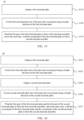
- a winding method including: outputting a first electrode plate; cutting the first electrode plate into a first part and a second part along a length direction of the first electrode plate; and winding the first part of the first electrode plate to form a first electrode assembly, and at the same time, winding the second part of the first electrode plate to form a second electrode assembly.
- the first electrode plate includes a first substrate and two first active coating regions applied to surfaces of the first substrate.
- the two first active coating regions are located on two sides of the first electrode plate in a width direction respectively.
- a first tab region extending along a length direction of the first electrode plate exists between the two first active coating regions.
- the cutting the first electrode plate into a first part and a second part along a length direction of the first electrode plate includes: performing cutting in the first tab region along the length direction of the first electrode plate, so as to cut the first electrode plate into the first part and the second part.
- the performing cutting in the first tab region along the length direction of the first electrode plate, so as to cut the first electrode plate into the first part and the second part includes: performing cutting in the first tab region along a first cutting line that extends in the length direction of the first electrode plate, so as to obtain the first part of the first electrode plate and form at least one tab of the first part of the first electrode plate; and performing cutting in the first tab region along a second cutting line that extends in the length direction of the first electrode plate, so as to obtain the second part of the first electrode plate and form at least one tab of the second part of the first electrode plate.
- the winding method further includes: outputting a second electrode plate; and cutting the second electrode plate into a first part and a second part along a length direction of the second electrode plate.
- the winding the first part of the first electrode plate to form a first electrode assembly, and at the same time, winding the second part of the first electrode plate to form a second electrode assembly include: winding the first part of the first electrode plate and the first part of the second electrode plate to form the first electrode assembly, and at the same time, winding the second part of the first electrode plate and the second part of the second electrode plate to form the second electrode assembly.
- the second electrode plate includes a second substrate and a second active coating region applied to a surface of the second substrate.
- a second tab region extending along a length direction of the second electrode plate exists on each of two sides of the second active coating region in a width direction of the second electrode plate.
- the cutting the second electrode plate into a first part and a second part along a length direction of the second electrode plate includes: performing cutting in the second active coating region along the length direction of the second electrode plate, so as to cut the second electrode plate into the first part and the second part.
- the winding method further includes: outputting two second electrode plates.
- the winding the first part of the first electrode plate to form a first electrode assembly, and at the same time, winding the second part of the first electrode plate to form a second electrode assembly include: winding the first part of the first electrode plate and one second electrode plate in the two second electrode plates to form the first electrode assembly, and at the same time, winding the second part of the first electrode plate and the other second electrode plate in the two second electrode plates to form the second electrode assembly.
- the second electrode plate includes a second substrate and a second active coating region applied to a surface of the second substrate.
- a second tab region extending along a length direction of the second electrode plate exists on one side of the second active coating region in a width direction of the second electrode plate.
- two electrode assemblies can be produced simultaneously by using only one first unwinding apparatus in coordination with the first cutting apparatus and the winding apparatus in the winding device.
- the winding device is efficient in manufacturing electrode assemblies, without requiring a large footprint in the shop floor, thereby improving the ratio of the footprint to the production capacity of the winding device, and increasing the maximum production capacity of the shop floor.
- a plurality of means at least two in number; the terms such as “up”, “down”, “left”, “right”, “in”, and “out” indicating a direction or a position relationship are merely intended for ease or brevity of description of this application, but do not indicate or imply that the mentioned device or component is necessarily located in the specified direction and position or constructed or operated in the specified direction and position. Therefore, such terms are not to be understood as a limitation on this application.
- the terms “first”, “second”, “third”, and so on are merely used for descriptive purposes, but not construed as indicating or implying relative importance.
- Perfect does not means exact perpendicularity, but means perpendicularity falling within an error tolerance range.
- Parallel does not mean exact parallelism, but means parallelism falling within an error tolerance range.
- connection may be a fixed connection, a detachable connection, or an integrated connection, and may be a direct connection or an indirect connection implemented through an intermediary.
- the term "and/or” merely indicates a relationship between related items, and represents three possible relationships.
- “A and/or B” may represent the following three circumstances: A alone, both A and B, and B alone.
- the character “/” herein generally indicates an "or” relationship between the item preceding the character and the item following the character.
- a battery means a physical module that includes one or more battery cells to provide electrical energy.
- the battery referred to herein may include a battery module, a battery pack, or the like.
- a battery typically includes a box configured to package one or more battery cells. The box prevents liquid or other foreign matters from affecting the charging or discharging of the battery cells.
- a battery cell may include a lithium-ion secondary battery, a lithium-ion primary battery, a lithium-sulfur battery, a sodium-lithium-ion battery, a sodium-ion battery, a magnesium-ion battery, or the like, without being limited in embodiments of this application.
- a battery cell is briefly referred to as a cell.
- a battery cell includes an electrode assembly and an electrolytic solution.
- the electrode assembly includes a positive electrode plate, a negative electrode plate, and a separator.
- the battery cell works primarily by relying on shuttling of metal ions between the positive electrode plate and the negative electrode plate.
- the positive electrode plate includes a positive current collector and a positive active material layer. A surface of the positive current collector is coated with the positive active material layer. Of the current collector, a part not coated with the positive active material layer protrudes from a part coated with the positive active material layer, and the part not coated with the positive active material layer serves as a positive tab.
- the positive current collector may be made of aluminum, and a positive active material may be lithium cobalt oxide, lithium iron phosphate, ternary lithium, lithium manganese oxide, or the like.
- the negative electrode plate includes a negative current collector and a negative active material layer. A surface of the negative current collector is coated with the negative active material layer. Of the current collector, a part not coated with the negative active material layer protrudes from a part coated with the negative active material layer, and the part not coated with the negative active material layer serves as a negative tab.
- the negative current collector may be made of copper, and a negative active material may be carbon, silicon, or the like.
- the separator may be made of a material such as polypropylene (polypropylene, PP) or polyethylene (polyethylene, PE).
- an electrode assembly of a battery cell assumes a jelly-roll structure.
- the jelly-roll electrode assembly may be in a cylindrical shape as a whole.
- the cylindrical electrode assembly fits in a cylindrical housing to form a cylindrical battery cell as a whole.
- the jelly-roll electrode assembly is formed by sequentially stacking a positive electrode plate, a negative electrode plate, and a separator in a flat spread-out state and then winding the stacked structure through a winding apparatus.
- the winding apparatus winds a stack of positive electrode plate, negative electrode plate, and separator to form an electrode assembly.
- the winding apparatus continues to wind another stack of positive electrode plate, negative electrode plate, and separators to form a next electrode assembly.
- Such a technical solution leads to relatively low production efficiency of the electrode assemblies, and hinders improvement of the production efficiency of battery cells and batteries.
- the winding apparatus can wind two stacks of positive electrode plates, negative electrode plates, and separators simultaneously to form two electrode assemblies.
- this technical solution can improve the production efficiency of electrode assemblies, two apparatuses configured to place the positive electrode plates, negative electrode plates, and separators need to be disposed during the manufacture, thereby requiring a relatively large footprint in the shop floor.
- this application provides a winding apparatus, in which an unwinding apparatus, a cutting apparatus, and a winding apparatus are contained.
- the unwinding apparatus is configured to supply an electrode plate.
- the cutting apparatus is configured to cut the electrode plate into a first part and a second part.
- the winding apparatus includes a first winding portion and a second winding portion capable of simultaneous winding movement.
- the first winding portion is configured to wind the first part of the first electrode plate to form a first electrode assembly
- the second winding portion is configured to wind the second part of the first electrode plate to form a second electrode assembly.
- the two parts can be wound by the two winding portions of the winding apparatus respectively to form two electrode assemblies. Therefore, only one unwinding apparatus is needed in the winding device. Two electrode assemblies can be obtained by simultaneous winding.
- the winding device is efficient in production, and requires just a relatively small footprint in the shop floor.
- FIG. 1 is a schematic structural diagram of a battery cell 10 according to an embodiment of this application.
- the battery cell 10 may include a housing 110 and an electrode assembly 120.
- the electrode assembly 120 is accommodated in the housing 110.
- the shape of the housing 110 depends on the shape of the electrode assembly 120.
- the electrode assembly 120 is cylindrical, and may be formed by stacking and winding a positive electrode plate, a separator, and a negative electrode plate (not shown in the drawing).
- the housing 110 is a hollow cylindrical housing that fits the electrode assembly 120.
- an opening is created on at least one surface of the housing 110. Through the opening, the electrode assembly 120 can be put into the housing 110 conveniently.
- openings are created on the end faces at both ends of the housing 110.
- the battery cell 10 may further include, in addition to the housing 110 and the electrode assembly 120, an end cap assembly to cover the opening of the housing 110.
- the battery cell 10 includes a first end cap assembly 130a and a second end cap assembly 130b.
- the two end cap assemblies cover the two ends of the hollow cylindrical housing 110 respectively, and are connected to the housing 110, so as form a closed cavity that is configured to accommodate the electrode assembly 120.
- the closed cavity not only accommodates the electrode assembly 120, but is also filled with an electrolyte such as an electrolyte solution.
- the first end cap assembly 130a includes a first end cap 131a and a first electrode terminal 132a.
- the first electrode terminal 132a may be mounted and fixed onto the first end cap 131a.
- the second end cap assembly 130b may also include a second end cap and a second electrode terminal.
- the second electrode terminal in the second end cap assembly 130b and the first electrode terminal 132a in the first end cap assembly 130a are two electrode terminals of opposite polarities. For example, when the first electrode terminal 132a is a positive electrode terminal, the second electrode terminal is a negative electrode terminal.
- the first end cap assembly 130a and the second end cap assembly 130b each may include a connecting component (not shown in FIG. 1 ) in addition to the end cap and the electrode terminal.
- the connecting component may also be referred to as a current collecting component, and is configured to electrically connect the electrode assembly 120 inside the battery cell 10 and the electrode terminal.
- the electrode assembly 120 may include a first tab 121a and a second tab 121b of opposite polarities.
- first tab 121a is a positive tab
- the second tab 121b is a negative tab.
- the first tab 121a and the second tab 121b are located on two end faces of the cylindrical electrode assembly 120 respectively.
- the two end faces of the cylindrical electrode assembly may be processed through a relevant process to form the two tabs.
- the first tab 121a of the electrode assembly 120 may be connected to the first electrode terminal 132a in the first end cap assembly 130a by one current collecting component.
- the second tab 121b of the electrode assembly 120 may be connected to the second electrode terminal in the second end cap assembly 130b by another current collecting component.
- FIG. 2 is a schematic structural diagram of a winding device 20 according to an embodiment of this application.
- the winding device 20 includes: a first unwinding apparatus 211, configured to output a first electrode plate 201; a first cutting apparatus 220, disposed downstream of the first unwinding apparatus 211, and configured to cut the first electrode plate 201 into a first part 201a and a second part 201b along a length direction of the first electrode plate 201; and a winding apparatus 230, disposed downstream of the first cutting apparatus 220, and including a first winding portion and a second winding portion capable of simultaneous winding movement.
- the first winding portion is configured to wind the first part 201a of the first electrode plate 201 to form a first electrode assembly.
- the second winding portion is configured to wind the second part 201b of the first electrode plate 201 to form a second electrode assembly.
- a rotatable shaft may be disposed in the first unwinding apparatus 211.
- the first electrode plate 201 is wound around the shaft layer by layer.
- the shaft rotates under a driving force, the first electrode plate 201 around the shaft is output in a flat spread-out state, so that the first unwinding apparatus 211 completes a web release action.
- a conveyor apparatus such as a plurality of roller structures shown in FIG. 2 or a conveyor belt, may be disposed downstream of the first unwinding apparatus 211.
- the conveyor apparatus may run through a plurality of processing apparatuses in the winding device 20 to circulate the first electrode plate 201 in the winding device 20.
- the first electrode plate 201 is in a strip shape in the winding device 20.
- the first electrode plate 201 is in the shape of a zigzag strip attached to a plurality of rollers.
- the length direction of the first electrode plate 201 is the length direction of the strip-shaped first electrode plate 201.
- the length direction of the first electrode plate 201 may be the transmission direction of the first electrode plate 201.
- the first cutting apparatus 220 is disposed downstream of the first unwinding apparatus 211, and is configured to receive the first electrode plate 201 output from the first unwinding apparatus 211, and cut the first electrode plate 201 into a first part 201a and a second part 201b along the length direction of the electrode plate.
- the first cutting apparatus 220 may be a laser die-cutting apparatus.
- the laser die-cutting apparatus is fixed into the winding device 20.
- the laser die-cutting apparatus can cut the first electrode plate 201 into the first part 201a and the second part 201b along the transmission direction of the first electrode plate 201.
- the winding apparatus 230 is disposed downstream of the first cutting apparatus 220. After the first cutting apparatus 220 cuts the first electrode plate 201 into the first part 201a and the second part 201b, the first part 201a and the second part 201b can be transmitted by the conveyor apparatus simultaneously and reach the winding apparatus 230.
- the winding apparatus 230 includes a first winding portion and a second winding portion capable of simultaneous winding movement.
- the first winding portion and the second winding portion are configured to receive the first part 201a the second part 201b of the first electrode plate 201 respectively.
- the first winding portion and the second winding portion can simultaneously wind the first part 201a and the second part 201b of the first electrode plate 201 to form a first electrode assembly and a second electrode assembly respectively.
- the first part 201a and the second part 201b of the first electrode plate 201 each may be configured to form two electrode assemblies.
- the first part 201a and the second part 201b of the first electrode plate 201 may serve as positive electrode plates in the two electrode assemblies respectively, or, the first part 201a and the second part 201b of the first electrode plate 201 may serve as negative electrode plates in the two electrode assemblies respectively.
- the winding apparatus 230 may be a winding needle.
- the winding needle includes two winding portions in the length direction, so as to make it convenient to wind the first part 201a and the second part of the first electrode plate 201 respectively.
- the winding device 20 includes a first cutting apparatus 220.
- the first cutting apparatus 220 can cut the first electrode plate 201 output by the first unwinding apparatus 211 into two parts. Subsequently, the two parts can be simultaneously wound by the two winding portions in the winding apparatus 230 respectively to form two electrode assemblies. Therefore, two electrode assemblies can be produced simultaneously by using only one first unwinding apparatus 211 in the winding device 20 in coordination with the first cutting apparatus 220 and the winding apparatus 230.
- the winding device 20 is efficient in manufacturing electrode assemblies, without requiring a large footprint in the shop floor, thereby improving the ratio of the footprint to the production capacity of the winding device 20, and increasing the maximum production capacity of the shop floor.
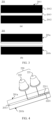
- FIG. 3 is a schematic diagram of a first electrode plate 201 before and after cutting according to an embodiment of this application.
- Subfigure (a) of FIG. 3 is a schematic diagram of a first electrode plate 201 before cutting
- subfigure (b) of FIG. 3 is a schematic diagram of the first electrode plate 201 after cutting.
- the first electrode plate 201 includes a first substrate 2011 and two first active coating regions 2012 applied to surfaces of the first substrate 2011.
- the two first active coating regions 2012 are located on two sides of the first electrode plate 201 in a width direction respectively.
- a first tab region 2013 extending along a length direction of the first electrode plate 201 exists between the two first active coating regions 2012.
- the first cutting apparatus 220 is configured to perform cutting in the first tab region 2013 along the length direction of the first electrode plate 201, so as to cut the first electrode plate 201 into the first part 201a and the second part 201b shown in subfigure (b) of FIG. 3 .
- the first active coating region 2012 applied on the first substrate 2011 may be a negative active material layer.
- the first substrate 2011 may be a copper substrate, and the first active coating region 2012 includes carbon or silicon.
- the first active coating region 2012 applied on the first substrate 2011 may be a positive active material layer.
- the first substrate 2011 may be an aluminum substrate, and the first active coating region 2012 includes lithium cobalt oxide, lithium iron phosphate, ternary lithium, lithium manganese oxide, or the like.
- the first substrate 2011 is coated with two first active coating regions 2012.
- the two first active coating regions 2012 are isolated by a first tab region 2013 located between the two first active coating regions.
- the first tab region 2013 is a region that is not coated with the first active coating region 2012 on the first substrate 2011.
- the two first active coating regions 2012 and the first tab region 2013 are all strip-shaped regions, and extend along the length direction of the first electrode plate 201.
- the lengths of the two first active coating regions 2012 and the first tab region 2013 may be close or identical to the length of the first electrode plate 201.
- the two first active coating regions 2012 are of the same dimension in the width direction of the first electrode plate 201, and the coverage of the two first active coating regions 2012 extends to the edges of the first electrode plate 201 on both sides in the width direction.
- the first tab region 2013 may be located at the center of the first electrode plate 201 in the width direction. The width of the first tab region 2013 may be designed based on the actually required tab size of the electrode assembly, and is not particularly limited herein.
- the first cutting apparatus 220 may further perform cutting along a centerline of the first tab region 2013 in the length direction, so as to form the first part 201a and the second part 201b of the same size.
- the first part 201a and the second part 201b of the same size include the first active coating regions 2012 of the same size and the tabs of the same size.
- the first part 201a and the second part 201b of the same size can be configured to be wound to form electrode assemblies of the same size.
- the first tab region 2013 may be deviated from the center of the first electrode plate 201 in the width direction.
- the first cutting apparatus 220 may cut the first electrode plate 201 into a first part 201a and a second part 201b of different sizes that are available for being wound to form electrode assemblies of different sizes.
- the first electrode plate 201 includes two first active coating regions 2012 and a first tab region 2013 located between the two first active coating regions 2012.
- the first electrode plate 201 is different from a conventional individual electrode plate configured to manufacture a single electrode assembly.
- the first electrode plate 201 includes two electrode plates (that is, the first part 201a and the second part 201b obtained by cutting) configured to manufacture two electrode assemblies.
- the first electrode plate 201 can be produced by the same coating process. In contrast to a technical solution in which two individual electrode plates are produced by two coating processes separately, the production efficiency of the first electrode plate 201 in the technical solutions hereof is higher.
- first tab region 2013 is located between the two first active coating regions 2012.
- the first cutting apparatus 220 performs cutting in the first tab region 2013, thereby dividing the electrode plate to obtain the first part 201a and the second part 201b, and at the same time, cutting the electrode plate to obtain a tab of the first part 201a and a tab of the second part 201b. In this way, the requirement for processing the tabs of the electrode assembly is fulfilled.
- the first cutting apparatus 220 may include just one cutting portion.
- the cutting portion is configured to form, in the first tab region 2013, a cutting line along which the first electrode plate 201 is cut into two parts.
- the one cutting line may be a straight line to form rectangular tabs in the first part 201a and the second part 201b shown in FIG. 3 ; or, the cutting line may be a wavy line, a polygonal line, or another line shape, to form tabs of other shapes.
- the overall cost of the first cutting apparatus 220 is relatively low, and the cutting method is simple to implement, and the cutting efficiency and quality are relatively high.
- the first cutting apparatus 200 may further include a plurality of cutting portions.
- the cutting portions are configured to form, in the first tab region 2013, a plurality of cutting lines along which the first electrode plate 201 is cut into a plurality of parts.
- FIG. 4 is a schematic diagram of cutting a first electrode plate 201 by a first cutting apparatus 220 according to an embodiment of this application.
- the first cutting apparatus 220 includes: a first cutting portion 221 and a second cutting portion 222.
- the first cutting portion 221 is configured to perform cutting in the first tab region 2013, so as to form at least one tab of the first part 201a of the first electrode plate 201.
- the second cutting portion 222 is configured to perform cutting in the first tab region 2013, so as to form at least one tab of the second part 201b of the first electrode plate 201.
- the first cutting portion 221 and the second cutting portion 222 may be two lasers arranged in parallel.
- a laser beam emitted by the first cutting portion 221 forms a first cutting line 2211 in the first tab region 2013.
- a laser beam emitted by the second cutting portion 222 forms a second cutting line 2221 in the first tab region 2013.
- the first cutting line 2211 and the second cutting line 2221 do not intersect, but both extend along the length direction of the first tab region 2013 (that is, the length direction of the first electrode plate 201).
- the first cutting line 2211 is configured to form the tab of the first part 201a of the first electrode plate 201.
- the second cutting line 2221 is configured to form the tab of the second part 201b of the first electrode plate 201.
- the first cutting line 2211 and the second cutting line 2221 may be in any preset shape such as a polygonal line shape or a wavy line shape.
- the shapes of the first cutting line 2211 and the second cutting line 2221 may be the same or different.
- the specific design of the first cutting line 2211 and the second cutting line 2221 is not particularly limited herein.
- the tabs of the first part 201a and the second part 201b of the first electrode plate 201 may include a plurality of trapezoidal or semicircular small tabs corresponding to the first cutting line 2211 and the second cutting line 2221.
- the first cutting portion 221 and the second cutting portion 222 are disposed in the first cutting apparatus 220.
- the two cutting portions can cut the first tab region 2013 in the first electrode plate 201 separately, so as to form the tab of the first part 201a and the tab of the second part 201b respectively.
- the first cutting portion 221 and the second cutting portion 222 can produce, in response to specific needs, the tab of the first part 201a of the first electrode plate 201 and the tab of the second part 201b of the first electrode plate 201, which are of a smaller size and a higher precision, thereby not only facilitating the subsequent manufacturing process of the electrode assembly such as tab processing in the wound electrode assembly, but also improving the overall performance of the electrode assembly.
- FIG. 5 is another schematic structural diagram of a winding device 20 according to an embodiment of this application.
- the winding device 20 further includes: a first adjustment assembly 241 and/or a second adjustment assembly 242, disposed between the first cutting apparatus 220 and the winding apparatus 230.
- the first adjustment assembly 241 is configured to adjust transmission parameters of the first part 201a of the first electrode plate 201 in the winding device 20, and/or, the second adjustment assembly 242 is configured to adjust transmission parameters of the second part 201b of the first electrode plate 201 in the winding device 20.
- a first adjustment assembly 241 is further disposed between the winding apparatus 230 and the first cutting apparatus 220 in the winding device 20 to adjust the first part 201a of the first electrode plate 201; and/or a second adjustment assembly 242 is further disposed between the winding apparatus and the first cutting apparatus to adjust the second part 201b of the first electrode plate 201.
- the first adjustment assembly 241 is configured to adjust transmission parameters of the first part 201a of the first electrode plate 201 in the winding device 20.
- the transmission parameters include, but are not limited to, tension, speed, direction, position, and the like of the first part 201a in the winding device 20.
- the second adjustment assembly 242 is configured to adjust transmission parameters of the second part 201b of the first electrode plate 201 in the winding device 20.
- the transmission parameters include, but are not limited to, tension, speed, direction, position, and the like of the second part 201b in the winding device 20.
- the transmission parameters of the first part 201a and/or the second part 201b of the first electrode plate 201 are adjusted by the first adjustment assembly 241 and/or the second adjustment assembly 242. In this way, the transmission of the first part 201a and/or the second part 201b in the winding device 20 is more stable. In addition, the subsequent winding effect of the first part 201a and/or the second part 201b in the winding apparatus 230 is improved, thereby improving the overall performance of the two produced electrode assemblies.
- the winding device 20 may include both a first adjustment assembly 241 and a second adjustment assembly 242 concurrently.
- the first adjustment assembly 241 and the second adjustment assembly 242 each may include a realignment assembly 2401.
- the realignment assembly 2401 in the first adjustment assembly 241 is configured to adjust a relative position of the first part 201a of the first electrode plate 201 in the winding device 20.
- the realignment assembly 2401 in the second adjustment assembly 242 is configured to adjust a relative position of the second part 201b of the first electrode plate 201 in the winding device 20.
- the two realignment assemblies 2401 can more pertinently adjust the relative positions of the first part 201a and the second part 201b of the first electrode plate 201 in the winding device 20 separately.
- the adjustment result is more accurate, thereby improving the winding effect of the first part 201a and the second part 201b of the first electrode plate 201 in the winding apparatus 230.
- first adjustment assembly 241 and the second adjustment assembly 242 each may further include a tension adjustment assembly 2402.
- the tension adjustment assembly 2402 in the first adjustment assembly 241 is configured to detect and adjust tension of the first part 201a of the first electrode plate 201.
- the realignment assembly 2401 in the second adjustment assembly 242 is configured to detect and adjust tension of the second part 201b of the first electrode plate 201.
- the tension adjustment assembly 2402 can more pertinently detect and adjust the tension of the first part 201a and the second part 201b of the first electrode plate 201 separately.
- the adjustment result is more accurate, thereby improving the transmission stability and reliability of the first part 201a and the second part 201b of the first electrode plate 201 in the winding device 20, and further improving the winding effect of the first part 201a and the second part 201b in the winding apparatus 230.
- the winding device 20 further includes: a first feeding apparatus 251, disposed upstream of the winding apparatus 230 and configured to convey the first part 201a and the second part 201b of the first electrode plate 201 to the winding apparatus 230.
- FIG. 6 is a schematic structural diagram of a first feeding apparatus 251 according to an embodiment of this application.
- the first feeding apparatus 251 includes: a first feeding portion 2511 and a second feeding portion 2512, disposed upstream of the winding apparatus 230.
- the first feeding portion 2511 is configured to convey the first part 201a of the first electrode plate 201 to the first winding portion of the winding apparatus 230.
- the second feeding portion 2512 is configured to convey the second part 201b of the first electrode plate 201 to the second winding portion of the winding apparatus 230.
- the two parts of the first electrode plate 201 are processed by the two feeding portions respectively.
- the two parts of the first electrode plate 201 can enter the two winding portions in the winding apparatus respectively in a more stable and reliable manner, thereby improving the winding effect of the two parts of the first electrode plate 201, and in turn, improving the performance of the two produced electrode assemblies.
- the first feeding portion 2511 may include: a first moving roller 2501, a first driving member 2502, and a first transmission member 2503.
- the second feeding portion 2512 may include: a second moving roller 2505, a second driving member 2506, and a second transmission member (not shown in the drawing).
- the first driving member 2502 is configured to drive the first moving roller 2501 to press and attach the first part 201a of the first electrode plate 201 to the first transmission member 2503.
- the first transmission member 2503 is configured to convey the first part 201a of the first electrode plate 201 to the first winding portion of the winding apparatus 230.
- the second driving member 2506 is configured to drive the second moving roller 2505 to press and attach the second part 201b of the first electrode plate 201 to the second transmission member.
- the second transmission member is configured to convey the second part 201b of the first electrode plate 201 to the second winding portion of the winding apparatus 230.
- the first transmission member 2503 may also be a roller structure. Relative to the first moving roller 2501, the first transmission member 2503 is a fixed roller. However, the fixed roller can actively rotate to drive the first part 201a of the first electrode plate 201 located on the fixed roller.
- the first transmission member 2503 and the first moving roller 2501 are located on two sides of the first part 201a of the first electrode plate 201 respectively.
- the first moving roller 2501 can move in a direction perpendicular to the first electrode plate 201 under the driving action of the first driving member 2502.
- the first moving roller 2501 moves toward the first part 201a of the first electrode plate 201, presses and attaches the first part 201a to the first transmission member 2503, thereby improving the transmission effect of the first transmission member 2503 for the first part 201a, and improving the transmission stability of the first part 201a.
- the first transmission member 2503 in the first feeding portion 2511 and the second transmission member in the second feeding portion 2512 may be two separate components.
- the first transmission member 2503 and the second transmission member may be one-piece components.
- the first transmission member 2503 and the second transmission member are the same fixed roller. The fixed roller corresponds to both the first part 201a and the second part 201b of the first electrode plate 201 simultaneously, and transmit the first part 201a and the second part 201b.
- the first feeding apparatus 251 may further include a clamping portion 2513 in addition to the first feeding portion 2511 and the second feeding portion 2512.
- the clamping portion is configured to clamp the first part 201a and the second part 201b of the first electrode plate 201, and enable the two parts to enter the subsequent two feeding portions smoothly and stably.
- the clamping portion 2513 may be two clamping rollers.
- the two clamping rollers are disposed on two sides of the first part 201a and the second part 201b of the first electrode plate 201 respectively, and can clamp the two parts firmly but without causing much resistance to the transmission of the two parts.
- the first feeding portion 2511 and the second feeding portion 2512 each include components such as a moving roller, a driving member, and a transmission member, and are easy to implement in overall structure and highly reliable, and can convey the two parts of the first electrode plate 201 into the winding apparatus 230 smoothly and efficiently.
- FIG. 6 is merely illustrative, and shows some components of the first feeding apparatus 251.
- the first feeding apparatus 251 may further include other functional components in the related art such as a cuter or another cutting component in addition to the components shown in FIG. 6 .
- FIG. 7 is another schematic structural diagram of a winding device 20 according to an embodiment of this application.
- the winding device 20 may further include: a second unwinding apparatus 212, configured to output a second electrode plate 202; and a second cutting apparatus 260, disposed downstream of the second unwinding apparatus 212, and configured to cut the second electrode plate 202 into a first part 202a and a second part 202b along a length direction of the second electrode plate 202.
- the winding apparatus 230 is disposed downstream of the second cutting apparatus 260.
- the first winding portion in the winding apparatus is configured to wind the first part 201a of the first electrode plate 201 and the first part 202a of the second electrode plate 202 to form the first electrode assembly.
- the second winding portion is configured to wind the second part 201b of the first electrode plate 201 and the second part 202b of the second electrode plate 202 to form the second electrode assembly.
- a rotatable shaft may be disposed in the second unwinding apparatus 212.
- the second electrode plate 202 is wound around the shaft layer by layer.
- the shaft rotates under a driving force, the second electrode plate 202 around the shaft is output in a flat spread-out state, so that the second unwinding apparatus 212 completes a web release action.
- a conveyor apparatus such as one or more roller structures or a conveyor belt, may be disposed downstream of the second unwinding apparatus 212.
- the conveyor apparatus may run through a plurality of processing apparatuses in the winding device 20 to circulate the second electrode plate 202 in the winding device 20.
- the second electrode plate 202 After being output by the second unwinding apparatus 212, the second electrode plate 202 is in a strip shape in the winding device 20.
- the second electrode plate 202 is in the shape of a zigzag strip attached to a plurality of rollers.
- the length direction of the second electrode plate 202 is the length direction of the strip-shaped second electrode plate 202.
- the length direction of the second electrode plate 202 may be the transmission direction of the second electrode plate 202.
- the second cutting apparatus 260 is disposed downstream of the second unwinding apparatus 212, and is configured to receive the second electrode plate 202 output from the second unwinding apparatus 212, and cut the second electrode plate 202 into a first part 202a and a second part 202b along the length direction of the electrode plate.
- the second cutting apparatus 260 may be a blade.
- the blade is fixed into the winding device 20.
- the blade can cut the second electrode plate 202 into the first part 202a and the second part 202b along the transmission direction of the second electrode plate 202.
- the winding apparatus 230 is disposed downstream of the first cutting apparatus 220 and the second cutting apparatus 260. After the first cutting apparatus 220 cuts the first electrode plate 201 into the first part 201a and the second part 201b, and, after the second cutting apparatus 260 cuts the second electrode plate 202 into the first part 202a and the second part 202b, the two parts of the first electrode plate 201 and the two parts of the second electrode plate 202 can be transmitted by the conveyor apparatus simultaneously and reach the winding apparatus 230.
- the first winding portion in the winding apparatus 230 is configured to receive the first part 201a of the first electrode plate 201 and the first part 202a of the second electrode plate 202, and stack and wind the two first parts to form the first electrode assembly.
- the second winding portion in the winding apparatus 230 is configured to receive the second part 201b of the first electrode plate 201 and the second part 202b of the second electrode plate 202, and stack and wind the two second parts to form the second electrode assembly.
- the first part 201a and the second part 201b of the first electrode plate 201 are positive electrode plates in the two electrode assemblies, then the first part 202a and the second part 202b of the second electrode plate 201 are negative electrode plates in the two electrode assemblies.
- the first part 201a and the second part 201b of the first electrode plate 201 are negative electrode plates in the two electrode assemblies, then the first part 202a and the second part 202b of the second electrode plate 201 are positive electrode plates in the two electrode assemblies.
- the winding device 20 includes a first cutting apparatus 220 and a second cutting apparatus 260 simultaneously.
- the first cutting apparatus 220 can cut the first electrode plate 201 output by the first unwinding apparatus 211 into two parts.
- the second cutting apparatus 260 can cut the second electrode plate 202 output by the second unwinding apparatus 212 into two parts. Subsequently, the two parts of the first electrode plate 201 and the two parts of the second electrode plate 202 can be simultaneously wound by the two winding portions in the winding apparatus 230 respectively to form two electrode assemblies.
- two electrode assemblies can be produced simultaneously by using only one first unwinding apparatus 211 and one second unwinding apparatus 212 in the winding device 20 in coordination with the first cutting apparatus 220, the second cutting apparatus 260, and the winding apparatus 230.
- the winding device 20 is efficient in manufacturing electrode assemblies, and can further reduce the footprint required in the shop floor, thereby further improving the ratio of the footprint to the production capacity of the winding device 20, and increasing the maximum production capacity of the shop floor.
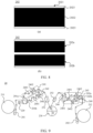
- FIG. 8 is a schematic diagram of a second electrode plate 202 before and after cutting according to an embodiment of this application.
- Subfigure (a) of FIG. 8 is a schematic diagram of a second electrode plate 201 before cutting
- subfigure (b) of FIG. 8 is a schematic diagram of the second electrode plate 202 after cutting.
- the second electrode plate 202 includes a second substrate 2021 and a second active coating region 2022 applied to a surface of the second substrate 2021.
- a second tab region 2023 extending along a length direction of the second electrode plate 202 exists on each of two sides of the second active coating region 2022 in a width direction of the second electrode plate 202.
- the second cutting apparatus 260 is configured to perform cutting in the second active coating region 2022 along the length direction of the second electrode plate 202, so as to cut the second electrode plate 202 into the first part 202a and the second part 202b.
- the second active coating region 2022 applied on the second substrate 2021 may be a positive active material layer.
- the second substrate 2021 may be an aluminum substrate, and the second active coating region 2022 includes lithium cobalt oxide, lithium iron phosphate, ternary lithium, lithium manganese oxide, or the like.
- the second active coating region 2022 applied on the second substrate 2021 may be a negative active material layer.
- the second substrate 2021 may be a copper substrate, and the second active coating region 2022 includes carbon or silicon.
- the second substrate 2021 is coated with one second active coating region 2022.
- the second active coating region 2022 includes two second tab regions 2023 on two sides in the width direction.
- the second tab regions 2023 are regions that are not coated with the second active coating region 2022 on the second substrate 2021.
- the second active coating region 2022 and the two second tab regions 2023 are all strip-shaped regions, and extend along the length direction of the second electrode plate 202.
- the lengths of the second active coating region 2022 and the two second tab regions 2023 may be close or identical to the length of the first electrode plate 201.
- the two second tab regions 2023 are of the same dimension in the width direction of the second electrode plate 202, and the coverage of the two second tab regions 2023 extends to the edges of the second electrode plate 202 on both sides in the width direction.
- the width of the second tab regions 2023 may be designed based on the actually required tab size of the electrode assembly, and is not particularly limited herein.
- the second cutting apparatus 260 may perform cutting along a centerline of the second active coating region 2022 in the length direction, so as to form the first part 202a and the second part 202b of the same size.
- the first part 202a and the second part 202b of the same size include the second active coating regions 2022 of the same size and the tabs of the same size.
- the first part 202a and the second part 202b of the same size can be configured to be wound to form electrode assemblies of the same size.
- the second cutting apparatus 260 may cut the second electrode plate 202 into a first part 202a and a second part 202b of different sizes that are available for being wound to form electrode assemblies of different sizes.
- the second electrode plate 202 includes the second active coating region 2022 and two second tab regions 2023 located on two sides of the second active coating region 2022 respectively.
- the second electrode plate 202 is different from a conventional individual electrode plate configured to manufacture a single electrode assembly.
- the second electrode plate 202 includes two electrode plates (that is, the first part 202a and the second part 202b obtained by cutting) configured to manufacture two electrode assemblies.
- the second electrode plate 202 can be produced by the same coating process. In contrast to a technical solution in which two individual electrode plates are produced by two coating processes separately, the production efficiency of the second electrode plate 202 in the technical solutions hereof is higher.
- FIG. 9 is another schematic structural diagram of a winding device 20 according to an embodiment of this application.
- the winding device 20 further includes: a third adjustment assembly 243 and/or a fourth adjustment assembly 244, disposed between the second cutting apparatus 260 and the winding apparatus 230.
- the third adjustment assembly 243 is configured to adjust transmission parameters of the first part 202a of the second electrode plate 202 in the winding device 20, and/or, the fourth adjustment assembly 244 is configured to adjust transmission parameters of the second part 202b of the second electrode plate 202 in the winding device 20.
- the third adjustment assembly 243 and the fourth adjustment assembly 244 include: a realignment assembly 2401, where the realignment assembly 2401 in the third adjustment assembly 243 is configured to adjust a relative position of the first part 202a of the second electrode plate 202 in the winding device 20, and the realignment assembly 2401 in the fourth adjustment assembly 244 is configured to adjust a relative position of the second part 202b of the second electrode plate 202 in the winding device 20; and/or the third adjustment assembly 243 and the fourth adjustment assembly 244 include: a tension adjustment assembly 2402, where the tension adjustment assembly 2402 in the third adjustment assembly 243 is configured to detect and adjust tension of the first part 202a of the second electrode plate 202, and the tension adjustment assembly 2402 in the fourth adjustment assembly 244 is configured to detect and adjust tension of the second part 202b of the second electrode plate 202.
- the transmission parameters of the first part 202a and/or the second part 202b of the second electrode plate 202 are adjusted by the third adjustment assembly 243 and/or the fourth adjustment assembly 244 respectively. In this way, the transmission of the first part 202a and/or the second part 202b in the winding device 20 is more stable. In addition, the subsequent winding effect of the first part 202a and/or the second part 202b in the winding apparatus 230 is improved, thereby improving the overall performance of the two produced electrode assemblies.
- the winding device 20 may further include: a second feeding apparatus 252, disposed upstream of the winding apparatus 230 and configured to convey the first part 202a and the second part 202b of the second electrode plate 202 to the winding apparatus 230.
- a second feeding apparatus 252 disposed upstream of the winding apparatus 230 and configured to convey the first part 202a and the second part 202b of the second electrode plate 202 to the winding apparatus 230.
- the winding device 20 includes only one second unwinding apparatus 212, and the second electrode plate 202 output by the second unwinding apparatus 212 is cut into two parts by the second cutting apparatus 260.
- the winding device 20 may include two second unwinding apparatuses 212. The second electrode plates 202 output by the two second unwinding apparatuses 212 do not need to be cut.
- FIG. 10 is another schematic structural diagram of a winding device 20 according to an embodiment of this application.
- the winding device 20 includes: two second unwinding apparatuses 212.
- Each second unwinding apparatus 212 in the two second unwinding apparatuses 212 is configured to output a second electrode plate 202.
- the winding apparatus 230 is disposed downstream of the two second unwinding apparatuses 212.
- the first winding portion in the winding apparatus is configured to wind the first part 201a of the first electrode plate 201 and the second electrode plate 202 from one of the second unwinding apparatuses 212 to form the first electrode assembly.
- the second winding portion is configured to wind the second part 201b of the first electrode plate 201 and the second electrode plate 202 from the other second unwinding apparatus 212 to form the second electrode assembly.
- the two second electrode plates 202 disposed on the two second unwinding apparatuses 212 may be the first part 202a and the second part 202b in the embodiment shown in FIG. 8 , respectively.
- the second electrode plate 202 is the electrode plate configured to form a single electrode assembly.
- the second electrode plate 202 includes a second substrate 2021 and a second active coating region 2022 applied to a surface of the second substrate 2021.
- a second tab region 2023 extending along a length direction of the second electrode plate 202 exists on one side of the second active coating region 2022 in a width direction of the second electrode plate 202.
- the winding device 20 includes two second unwinding apparatuses 212.
- the second electrode plate 202 disposed on the two second unwinding apparatuses 212 is an electrode plate in a single electrode assembly, and does not need to be cut.
- the positions of the two second electrode plates 202 output by the two second unwinding apparatuses 212 do not need to be much adjusted subsequently, and the two second electrode plates 202 can coordinate with the two parts of the first electrode plate 201 to undergo a winding process and form two electrode assemblies. Therefore, based on such technical solutions, the transmission of the second electrode plate 202 in the winding device 20 is more stable, and the performance and yield rate of the electrode assemblies produced by the winding device 20 are improved.
- an adjustment assembly is disposed downstream of the second unwinding apparatus 212.
- the third adjustment assembly 243 and the fourth adjustment assembly 244 are disposed downstream of the two second unwinding apparatuses 212 respectively.
- the third adjustment assembly 243 and the fourth adjustment assembly 244 are configured to adjust transmission parameters of the two second electrode plates 202 from the two second unwinding apparatuses 212 in the winding device 20.
- FIG. 11 is a schematic structural diagram of another winding device 20 according to an embodiment of this application.
- the winding device 20 further includes: two third unwinding apparatuses 213, where each third unwinding apparatus 213 in the two third unwinding apparatuses 213 is configured to output a first separator 203; and two fourth unwinding apparatuses 214, where each fourth unwinding apparatus 214 in the two fourth unwinding apparatuses 214 is configured to output a second separator 204.
- the winding apparatus 230 is disposed downstream of the two third unwinding apparatuses 213 and the two fourth unwinding apparatuses 214.
- the first winding portion in the winding apparatus is configured to wind the first part 201a of the first electrode plate 201, the first separator 203 from one third unwinding apparatus 213, and the second separator 204 from one fourth unwinding apparatus 214 to form the first electrode assembly.
- the second winding portion is configured to wind the second part 201b of the first electrode plate 201, the first separator 203 from the other third unwinding apparatus 213, and the second separator 204 from the other fourth unwinding apparatus 214 to form the second electrode assembly.
- the first separator 203 and the second separator 204 are configured to isolate the positive electrode plate from the negative electrode plate, and are wound together with the positive and negative electrode plates to form an electrode assembly.
- each winding portion in the winding apparatus 230 may receive four incoming materials, that is, the first separator 203, the second separator 204, a part of the first electrode plate 201, and a part of the second electrode plate 202.
- FIG. 12 is a schematic structural diagram of a winding apparatus 230 according to an embodiment of this application.
- the first winding portion 231 and the second winding portion 232 in the winding apparatus 230 are arranged along an axial direction of the winding apparatus 230.
- the first winding portion 231 in the winding apparatus 230 is configured to receive one first separator 203, the first part 201a of the first electrode plate 201, one second separator 204, and the first part 202a of the second electrode plate 202 simultaneously, and wind the four incoming materials.
- the second winding portion 232 arranged in parallel with the first winding portion 231 is configured to receive the other first separator 203, the second part 201b of the first electrode plate 201, the other second separator 204, and the second part 202b of the second electrode plate 202 simultaneously, and wind the four incoming materials.
- two first separators 203 are output by two third unwinding apparatuses 213.
- Two second separators 204 are output by two fourth unwinding apparatuses 214.
- the two first separators 203 and the two second separators 204 can be conveyed to the two winding portions in the winding apparatus 230 simultaneously, so as to be wound synchronously with the two parts of the first electrode plate to form two electrode assemblies of stable performance that can operate reliably.
- the manufacturing efficiency of the electrode assemblies is relatively high.
- the winding device 20 further includes: a first combining apparatus 271, disposed between the two third unwinding apparatuses 213 and the winding apparatus 230, where the first combining apparatus 271 includes two first rotating portions (not shown in the drawing) disposed on the same roller, the two first rotating portions correspond one-to-one to the two third unwinding apparatuses 213 and the two winding portions in the winding apparatus 230, and each of the first rotating portions is configured to convey the first separator 203 from a corresponding third unwinding apparatus 213 to a corresponding winding portion; and/or
- a second combining apparatus 272 disposed between the two fourth unwinding apparatuses 214 and the winding apparatus 230, where the second combining apparatus 272 includes two second rotating portions (not shown in the drawing) disposed on the same roller, the two second rotating portions correspond one-to-one to the two fourth unwinding apparatuses 214 and the two winding portions in the winding apparatus 230, and each of the second rotating portions is configured to convey the second separator 204 from a corresponding fourth unwinding apparatus 214 to a corresponding winding portion.
- FIG. 13 is a schematic structural diagram of a first combining apparatus 271 according to an embodiment of this application.
- the first combining apparatus 271 includes: a fixed portion 2712, an idler roller 2713, and two mutually separated first rotating portions 2711 disposed on the idler roller 2713.
- One end of the idler roller 2713 in the axial direction is fixed to the fixed portion 2712.
- the two first rotating portions 2711 are two separate bearing positions on the idler roller 2713, and are configured to receive the two separated first separators 203 respectively.
- the two first rotating portions 2711 correspond one-to-one to the two third unwinding apparatuses 213.
- the two first rotating portions 2711 correspond one-to-one to the two winding portions, that is, the first winding portion 231 and the second winding portion 232, in the winding apparatus 230.
- One first rotating portion 2711, a corresponding third unwinding apparatus 213, and a corresponding winding portion form a winding assembly.
- the winding assembly is configured to wind one first separator 203 onto one winding portion.
- the specific structure of the second combining apparatus 272 may be the same as the first combining apparatus 271.
- the two first separators 203 can be conveyed to the two winding portions in the winding apparatus 230 by the same first combining apparatus 271.
- the two second separators 204 can also be conveyed to the two winding portions in the winding apparatus 230 by the same second combining apparatus 272.
- FIG. 14 is another schematic structural diagram of a winding device 20 according to an embodiment of this application.
- the winding device 20 further includes:
- the fifth adjustment assembly 245 and the sixth adjustment assembly 246 include: a tension adjustment assembly 2402, where the tension adjustment assembly 2402 in the fifth adjustment assembly 245 is configured to detect and adjust tension of the first separator 203, and the tension adjustment assembly 2402 in the sixth adjustment assembly 246 is configured to detect and adjust tension of the second separator 204.
- the transmission parameters of the first separator 203 and/or the second separator 204 are adjusted by the fifth adjustment assembly 245 and/or the sixth adjustment assembly 246. In this way, the transmission of the first separator 203 and/or the second separator 204 in the winding device 20 is more stable. In addition, the subsequent winding effect of the first separator 203 and/or the second separator 204 in the winding apparatus 230 is improved, thereby improving the overall performance of the two produced electrode assemblies.
- the winding device 20 includes: one second unwinding apparatus 212 and a second cutting apparatus 260 as shown in FIG. 7 or FIG. 9 .
- the winding device 20 may include two second unwinding apparatuses 212 as shown in FIG. 10 .
- the above application embodiments are described by using an example in which the first cutting apparatus 220 cuts the first electrode plate 201 into two parts.
- the first cutting apparatus 220 may cut the first electrode plate 201 into three or more parts.
- the winding apparatus 230 can wind three or more parts of the first electrode plates simultaneously to manufacture three or more electrode assemblies at the same time.
- the winding device 20 according to some embodiments of this application have been described above.
- the following describes a winding method 30 according to an embodiment of this application.
- FIG. 15 is a schematic flow block diagram of a winding method 30 according to an embodiment of this application.
- the winding method 30 includes the following steps:
- the first electrode plate 201 includes a first substrate 2011 and two first active coating regions 2012 applied to surfaces of the first substrate 2011.
- the two first active coating regions 2012 are located on two sides of the first electrode plate 201 in a width direction respectively.
- a first tab region 2013 extending along a length direction of the first electrode plate 201 exists between the two first active coating regions 2012.
- step S320 may include: performing cutting in the first tab region 2013 along the length direction of the first electrode plate 201, so as to cut the first electrode plate 201 into the first part 201a and the second part 201b.
- the "performing cutting in the first tab region 2013 along the length direction of the first electrode plate 201, so as to cut the first electrode plate 201 into the first part 201a and the second part 201b" may include: performing cutting in the first tab region 2013 along a first cutting line 2211 that extends in the length direction of the first electrode plate 201, so as to obtain the first part 201a of the first electrode plate 201 and form at least one tab of the first part 201a of the first electrode plate 201; and performing cutting in the first tab region 2013 along a second cutting line 2221 that extends in the length direction of the first electrode plate 201, so as to obtain the second part 201b of the first electrode plate 201 and form at least one tab of the second part 201b of the first electrode plate 201.
- FIG. 16 is another schematic flow block diagram of a winding method 30 according to an embodiment of this application.
- the winding method 30 may further include the following steps in addition to the above steps S310 and S320:
- step S330 may include the following step S331:
- S331 Winding the first part 201a of the first electrode plate 201 and the first part 202a of the second electrode plate 202 to form the first electrode assembly, and at the same time, winding the second part 201b of the first electrode plate 201 and the second part 202b of the second electrode plate 202 to form the second electrode assembly.
- the second electrode plate 202 includes a second substrate 2021 and a second active coating region 2022 applied to a surface of the second substrate 2021.
- a second tab region 2023 extending along a length direction of the second electrode plate 202 exists on each of two sides of the second active coating region 2022 in a width direction of the second electrode plate 202.
- step S350 may include: performing cutting in the second active coating region 2022 along the length direction of the second electrode plate 202, so as to cut the second electrode plate 202 into the first part 202a and the second part 202b.
- FIG. 17 is another schematic flow block diagram of a winding method 30 according to an embodiment of this application.
- the winding method 30 may further include the following steps in addition to the above steps S310 and S320:
- step S330 may include the following step S332.
- S332 Winding the first part 201a of the first electrode plate 201 and one second electrode plate 202 in the two second electrode plates 202 to form the first electrode assembly, and at the same time, winding the second part 201b of the first electrode plate 201 and the other second electrode plate 202 in the two second electrode plates 202 to form the second electrode assembly.
- the second electrode plate 202 includes a second substrate 2021 and a second active coating region 2022 applied to a surface of the second substrate 2021.
- a second tab region 2023 extending along a length direction of the second electrode plate 202 exists on one side of the second active coating region 2022 in a width direction of the second electrode plate 202.
Landscapes
- Chemical & Material Sciences (AREA)
- Chemical Kinetics & Catalysis (AREA)
- Electrochemistry (AREA)
- General Chemical & Material Sciences (AREA)
- Engineering & Computer Science (AREA)
- Manufacturing & Machinery (AREA)
- Battery Electrode And Active Subsutance (AREA)
- Secondary Cells (AREA)
Abstract
Description
- This application claims priority to
Chinese Patent Application No. 202210271281.9, filed on March 18, 2022 - Some embodiments of this application relate to the field of mechanics, and in particular, to a winding device and a winding method.
- Energy conservation and emission reduction are key to sustainable development of the automobile industry. Electric vehicles have become an important part of the sustainable development of the automobile industry by virtue of energy saving and environmental friendliness. Battery technology is crucial to development of electric vehicles.
- Generally, a battery includes one or more battery cells. Each battery cell includes an electrode assembly. The electrode assembly includes a positive electrode plate, a negative electrode plate, and a separator. In some related technologies, the positive electrode plate, negative electrode plate, and separator can be wound by a winding device to form a jelly-roll electrode assembly. How to improve the processing efficiency of the winding device for electrode assemblies to increase the production capacity of batteries is an urgent technical problem.
- This application provides a winding device and method to improve the processing efficiency of the winding device for electrode assemblies to increase the production capacity of batteries.
- According to a first aspect, a winding device is provided, including: a first unwinding apparatus, configured to output a first electrode plate; a first cutting apparatus, disposed downstream of the first unwinding apparatus, and configured to cut the first electrode plate into a first part and a second part along a length direction of the first electrode plate; and a winding apparatus, disposed downstream of the first cutting apparatus, and including a first winding portion and a second winding portion capable of simultaneous winding movement. The first winding portion is configured to wind the first part of the first electrode plate to form a first electrode assembly. The second winding portion is configured to wind the second part of the first electrode plate to form a second electrode assembly.
- Based on the technical solution disclosed in an embodiment of this application, two electrode assemblies can be produced simultaneously by using only one first unwinding apparatus in coordination with the first cutting apparatus and the winding apparatus in the winding device. The winding device is efficient in manufacturing electrode assemblies, without requiring a large footprint in the shop floor, thereby improving the ratio of the footprint to the production capacity of the winding device, and increasing the maximum production capacity of the shop floor.
- In some possible embodiments, the first electrode plate includes a first substrate and two first active coating regions applied to surfaces of the first substrate. The two first active coating regions are located on two sides of the first electrode plate in a width direction respectively. A first tab region extending along a length direction of the first electrode plate exists between the two first active coating regions. The first cutting apparatus is configured to perform cutting in the first tab region along the length direction of the first electrode plate, so as to cut the first electrode plate into the first part and the second part.
- Based on the technical solutions disclosed in these embodiments, the first electrode plate includes two first active coating regions and a first tab region located between the two first active coating regions. The first electrode plate is different from a conventional individual electrode plate configured to manufacture a single electrode assembly. The first electrode plate includes two electrode plates (that is, the first part and the second part obtained by cutting) configured to manufacture two electrode assemblies. The first electrode plate can be produced by the same coating process. In contrast to a technical solution in which two individual electrode plates are produced by two coating processes separately, the production efficiency of the first electrode plate in the technical solutions hereof is higher.
- In some possible embodiments, the first cutting apparatus includes: a first cutting portion and a second cutting portion. The first cutting portion is configured to perform cutting in the first tab region, so as to form at least one tab of the first part of the first electrode plate. The second cutting portion is configured to perform cutting in the first tab region, so as to form at least one tab of the second part of the first electrode plate.
- Based on the technical solutions disclosed in these embodiments, the first cutting portion and the second cutting portion are disposed in the first cutting apparatus, so as to produce, in response to specific needs, the tab of the first part of the first electrode plate and the tab of the second part of the first electrode plate, which are of a smaller size and a higher precision, thereby not only facilitating the subsequent manufacturing process of the electrode assembly such as tab processing in the wound electrode assembly, but also improving the overall performance of the electrode assembly.
- In some possible embodiments, the winding device further includes: a first adjustment assembly and/or a second adjustment assembly, disposed between the first cutting apparatus and the winding apparatus, where the first adjustment assembly is configured to adjust transmission parameters of the first part of the first electrode plate in the winding device, and/or, the second adjustment assembly is configured to adjust transmission parameters of the second part of the first electrode plate in the winding device.
- In the technical solutions in these embodiments, the transmission parameters of the first part and/or the second part of the first electrode plate are adjusted by the first adjustment assembly and/or the second adjustment assembly. In this way, the transmission of the first part and/or the second part in the winding device is more stable. In addition, the subsequent winding effect of the first part and/or the second part in the winding apparatus is improved, thereby improving the overall performance of the two produced electrode assemblies.
- In some possible embodiments, the first adjustment assembly and the second adjustment assembly include: a realignment assembly, where the realignment assembly in the first adjustment assembly is configured to adjust a relative position of the first part of the first electrode plate in the winding device, and the realignment assembly in the second adjustment assembly is configured to adjust a relative position of the second part of the first electrode plate in the winding device; and/or the first adjustment assembly and the second adjustment assembly include: a tension adjustment assembly, where the tension adjustment assembly in the first adjustment assembly is configured to detect and adjust tension of the first part of the first electrode plate, and the tension adjustment assembly in the second adjustment assembly is configured to detect and adjust tension of the second part of the first electrode plate.
- In the technical solutions in these embodiments, the realignment assembly and the tension adjustment assembly are disposed in both the first adjustment assembly and the second adjustment assembly. In this way, the two realignment assemblies and the two tension adjustment assemblies can more pertinently adjust the relative positions and tension of the first part and the second part of the first electrode plate in the winding device separately. The adjustment result is more accurate, thereby improving the winding effect of the first part and the second part of the first electrode plate in the winding apparatus.
- In some possible embodiments, the winding device further includes: a first feeding portion and a second feeding portion, disposed upstream of the winding apparatus. The first feeding portion is configured to convey the first part of the first electrode plate to the first winding portion of the winding apparatus. The second feeding portion is configured to convey the second part of the first electrode plate to the second winding portion of the winding apparatus.
- In the technical solutions in these embodiments, the two parts of the first electrode plate are processed by the two feeding portions respectively. In this way, the two parts of the first electrode plate can enter the two winding portions in the winding apparatus respectively in a more stable and reliable manner, thereby improving the winding effect of the two parts of the first electrode plate, and in turn, improving the performance of the two produced electrode assemblies.
- In some possible embodiments, the first feeding portion includes: a first moving roller, a first driving member, and a first transmission member. The second feeding portion includes: a second moving roller, a second driving member, and a second transmission member. The first driving member is configured to drive the first moving roller to press and attach the first part of the first electrode plate to the first transmission member. The first transmission member is configured to convey the first part of the first electrode plate to the first winding portion. The second driving member is configured to drive the second moving roller to press and attach the second part of the first electrode plate to the second transmission member. The second transmission member is configured to convey the second part of the first electrode plate to the second winding portion.
- In the technical solutions in these embodiments, the first feeding portion and the second feeding portion each include a moving roller, a driving member, and a transmission member, and are easy to implement in overall structure and highly reliable, and can convey the two parts of the first electrode plate into the winding apparatus smoothly and efficiently.
- In some possible embodiments, the winding device further includes: a second unwinding apparatus, configured to output a second electrode plate; a second cutting apparatus, disposed downstream of the second unwinding apparatus, and configured to cut the second electrode plate into a first part and a second part along a length direction of the second electrode plate; and the winding apparatus, disposed downstream of the second cutting apparatus. The first winding portion is configured to wind the first part of the first electrode plate and the first part of the second electrode plate to form the first electrode assembly. The second winding portion is configured to wind the second part of the first electrode plate and the second part of the second electrode plate to form the second electrode assembly.
- Based on the technical solutions disclosed in these embodiments, two electrode assemblies can be produced simultaneously by using only one first unwinding apparatus and one second unwinding apparatus in coordination with the first cutting apparatus, the second cutting apparatus, and the winding apparatus in the winding device. The winding device is efficient in manufacturing electrode assemblies, and can further reduce the footprint required in the shop floor, thereby further improving the ratio of the footprint to the production capacity of the winding device, and increasing the maximum production capacity of the shop floor.
- In some possible embodiments, the second electrode plate includes a second substrate and a second active coating region applied to a surface of the second substrate. A second tab region extending along a length direction of the second electrode plate exists on each of two sides of the second active coating region in a width direction of the second electrode plate. The second cutting apparatus is configured to perform cutting in the second active coating region along the length direction of the second electrode plate, so as to cut the second electrode plate into the first part and the second part.
- Based on the technical solutions disclosed in these embodiments, the second electrode plate includes a second active coating region and two second tab regions located on the two sides of the second active coating region respectively. The second electrode plate is different from a conventional individual electrode plate configured to manufacture a single electrode assembly. The second electrode plate includes two electrode plates (that is, the first part and the second part obtained by cutting) configured to manufacture two electrode assemblies. The second electrode plate can be produced by the same coating process. In contrast to a technical solution in which two individual electrode plates are produced by two coating processes separately, the production efficiency of the second electrode plate in the technical solutions hereof is higher.
- In some possible embodiments, the winding device further includes: a third adjustment assembly and/or a fourth adjustment assembly, disposed between the second cutting apparatus and the winding apparatus. The third adjustment assembly is configured to adjust transmission parameters of the first part of the second electrode plate in the winding device, and/or, the fourth adjustment assembly is configured to adjust transmission parameters of the second part of the second electrode plate in the winding device.
- In the technical solutions in these embodiments, the transmission parameters of the first part and/or the second part of the second electrode plate are adjusted by the third adjustment assembly and/or the fourth adjustment assembly respectively. In this way, the transmission of the first part and/or the second part in the winding device is more stable. In addition, the subsequent winding effect of the first part and/or the second part in the winding apparatus is improved, thereby improving the overall performance of the two produced electrode assemblies.
- In some possible embodiments, the third adjustment assembly and the fourth adjustment assembly include: a realignment assembly, where the realignment assembly in the third adjustment assembly is configured to adjust a relative position of the first part of the second electrode plate in the winding device, and the realignment assembly in the fourth adjustment assembly is configured to adjust a relative position of the second part of the second electrode plate in the winding device; and/or the third adjustment assembly and the fourth adjustment assembly include: a tension adjustment assembly, where the tension adjustment assembly in the third adjustment assembly is configured to detect and adjust tension of the first part of the second electrode plate, and the tension adjustment assembly in the fourth adjustment assembly is configured to detect and adjust tension of the second part of the second electrode plate.
- In some possible embodiments, the winding device further includes: two second unwinding apparatuses, where each second unwinding apparatus in the two second unwinding apparatuses is configured to output a second electrode plate; and the winding apparatus, disposed downstream of the two second unwinding apparatuses. The first winding portion is configured to wind the first part of the first electrode plate and the second electrode plate from one of the second unwinding apparatuses to form the first electrode assembly, and the second winding portion is configured to wind the second part of the first electrode plate and the second electrode plate from the other second unwinding apparatus to form the second electrode assembly.
- In the technical solutions in these embodiments, the winding device includes two second unwinding apparatuses. The second electrode plate disposed on the two second unwinding apparatuses is an electrode plate in a single electrode assembly, and does not need to be cut. In these embodiments, the positions of the two second electrode plates output by the two second unwinding apparatuses do not need to be much adjusted subsequently, and the two second electrode plates can coordinate with the two parts of the first electrode plate to undergo a winding process and form two electrode assemblies. Therefore, based on such technical solutions, the transmission of the second electrode plate in the winding device is more stable, and the performance and yield rate of the electrode assemblies produced by the winding device are improved.
- In some possible embodiments, the second electrode plate includes a second substrate and a second active coating region applied to a surface of the second substrate. A second tab region extending along a length direction of the second electrode plate exists on one side of the second active coating region in a width direction of the second electrode plate.
- In some possible embodiments, the winding device further includes: two third unwinding apparatuses, where each third unwinding apparatus in the two third unwinding apparatuses is configured to output a first separator; two fourth unwinding apparatuses, where each fourth unwinding apparatus in the two fourth unwinding apparatuses is configured to output a second separator; the winding apparatus, disposed downstream of the two third unwinding apparatuses and the two fourth unwinding apparatuses. The first winding portion is configured to wind the first part of the first electrode plate, the first separator from one of the third unwinding apparatuses, and the second separator from one of the fourth unwinding apparatuses to form the first electrode assembly. The second winding portion is configured to wind the second part of the first electrode plate, the first separator from the other third unwinding apparatus, and the second separator from the other fourth unwinding apparatus to form the second electrode assembly.
- In the technical solutions in these embodiments, two first separators are output by two third unwinding apparatuses, and two second separators are output by two fourth unwinding apparatuses. The two first separators and the two second separators can be conveyed to the two winding portions in the winding apparatus simultaneously, so as to be wound synchronously with the two parts of the first electrode plate to form two electrode assemblies of stable performance that can operate reliably. The manufacturing efficiency of the electrode assemblies is relatively high.
- In some possible embodiments, the winding device further includes: a first combining apparatus, disposed between the two third unwinding apparatuses and the winding apparatus, where the first combining apparatus includes two first rotating portions disposed on a same roller, the two first rotating portions correspond one-to-one to the two third unwinding apparatuses and the two winding portions in the winding apparatus, and each of the first rotating portions is configured to convey the first separator from a corresponding third unwinding apparatus to a corresponding winding portion; and/or a second combining apparatus, disposed between the two fourth unwinding apparatuses and the winding apparatus. The second combining apparatus includes two second rotating portions disposed on a same roller. The two second rotating portions correspond one-to-one to the two fourth unwinding apparatuses and the two winding portions in the winding apparatus. Each of the second rotating portions is configured to convey the second separator from a corresponding fourth unwinding apparatus to a corresponding winding portion.
- Based on the technical solutions disclosed in these embodiments, the two first separators can be conveyed to the two winding portions in the winding apparatus by the same first combining apparatus. Similarly, the two second separators can also be conveyed to the two winding portions in the winding apparatus by the same second combining apparatus. In these embodiments, it is not necessary to convey the two first separators to the winding apparatus separately by using a plurality of apparatuses, and it is not necessary to convey the two second separators to the winding apparatus separately by using a plurality of apparatuses, thereby reducing the number of apparatuses in the winding device, and further reducing the footprint of the winding device in the shop floor.
- In some possible embodiments, the winding device further includes: two fifth adjustment assemblies, corresponding one-to-one to the two third unwinding apparatuses, and disposed between the first combining apparatus and the two third unwinding apparatuses, where each of the fifth adjustment assemblies is configured to adjust transmission parameters of the first separator in the winding device; and/or two sixth adjustment assemblies, corresponding one-to-one to the two fourth unwinding apparatuses, and disposed between the second combining apparatus and the two fourth unwinding apparatuses, where each of the sixth adjustment assemblies is configured to adjust transmission parameters of the second separator in the winding device.
- In the technical solutions in these embodiments of this application, the transmission parameters of the first separator and/or the second separator are adjusted by the fifth adjustment assembly and/or the sixth adjustment assembly. In this way, the transmission of the first separator and/or the second separator in the winding device is more stable. In addition, the subsequent winding effect of the first separator and/or the second separator in the winding apparatus is improved, thereby improving the overall performance of the two produced electrode assemblies.
- In some possible embodiments, the fifth adjustment assembly and the sixth adjustment assembly include: a tension adjustment assembly, where the tension adjustment assembly in the fifth adjustment assembly is configured to detect and adjust tension of the first separator, and the tension adjustment assembly in the sixth adjustment assembly is configured to detect and adjust tension of the second separator.
- According to a second aspect, a winding method is provided, including: outputting a first electrode plate; cutting the first electrode plate into a first part and a second part along a length direction of the first electrode plate; and winding the first part of the first electrode plate to form a first electrode assembly, and at the same time, winding the second part of the first electrode plate to form a second electrode assembly.
- In some possible embodiments, the first electrode plate includes a first substrate and two first active coating regions applied to surfaces of the first substrate. The two first active coating regions are located on two sides of the first electrode plate in a width direction respectively. A first tab region extending along a length direction of the first electrode plate exists between the two first active coating regions. The cutting the first electrode plate into a first part and a second part along a length direction of the first electrode plate includes: performing cutting in the first tab region along the length direction of the first electrode plate, so as to cut the first electrode plate into the first part and the second part.
- In some possible embodiments, the performing cutting in the first tab region along the length direction of the first electrode plate, so as to cut the first electrode plate into the first part and the second part includes: performing cutting in the first tab region along a first cutting line that extends in the length direction of the first electrode plate, so as to obtain the first part of the first electrode plate and form at least one tab of the first part of the first electrode plate; and performing cutting in the first tab region along a second cutting line that extends in the length direction of the first electrode plate, so as to obtain the second part of the first electrode plate and form at least one tab of the second part of the first electrode plate.
- In some possible embodiments, the winding method further includes: outputting a second electrode plate; and cutting the second electrode plate into a first part and a second part along a length direction of the second electrode plate. The winding the first part of the first electrode plate to form a first electrode assembly, and at the same time, winding the second part of the first electrode plate to form a second electrode assembly, include: winding the first part of the first electrode plate and the first part of the second electrode plate to form the first electrode assembly, and at the same time, winding the second part of the first electrode plate and the second part of the second electrode plate to form the second electrode assembly.
- In some possible embodiments, the second electrode plate includes a second substrate and a second active coating region applied to a surface of the second substrate. A second tab region extending along a length direction of the second electrode plate exists on each of two sides of the second active coating region in a width direction of the second electrode plate. The cutting the second electrode plate into a first part and a second part along a length direction of the second electrode plate includes: performing cutting in the second active coating region along the length direction of the second electrode plate, so as to cut the second electrode plate into the first part and the second part.
- In some possible embodiments, the winding method further includes: outputting two second electrode plates. The winding the first part of the first electrode plate to form a first electrode assembly, and at the same time, winding the second part of the first electrode plate to form a second electrode assembly, include: winding the first part of the first electrode plate and one second electrode plate in the two second electrode plates to form the first electrode assembly, and at the same time, winding the second part of the first electrode plate and the other second electrode plate in the two second electrode plates to form the second electrode assembly.
- In some possible embodiments, the second electrode plate includes a second substrate and a second active coating region applied to a surface of the second substrate. A second tab region extending along a length direction of the second electrode plate exists on one side of the second active coating region in a width direction of the second electrode plate.
- Based on the technical solution disclosed in an embodiment of this application, two electrode assemblies can be produced simultaneously by using only one first unwinding apparatus in coordination with the first cutting apparatus and the winding apparatus in the winding device. The winding device is efficient in manufacturing electrode assemblies, without requiring a large footprint in the shop floor, thereby improving the ratio of the footprint to the production capacity of the winding device, and increasing the maximum production capacity of the shop floor.
- To describe the technical solutions of some embodiments of this application more clearly, the following outlines the drawings used in the embodiments of this application. Evidently, the drawings outlined below are merely a part of embodiments of this application. A person of ordinary skill in the art may derive other drawings from the outlined drawings without making any creative efforts.
-
FIG. 1 is a schematic structural diagram of a battery cell according to an embodiment of this application; -
FIG. 2 is a schematic structural diagram of a winding device according to an embodiment of this application. -
FIG. 3 is a schematic diagram of a first electrode plate before and after cutting according to an embodiment of this application; -
FIG. 4 is a schematic diagram of cutting a first electrode plate by a first cutting apparatus according to an embodiment of this application; -
FIG. 5 is another schematic structural diagram of a winding device according to an embodiment of this application; -
FIG. 6 is a schematic structural diagram of a first feeding apparatus according to an embodiment of this application; -
FIG. 7 is another schematic structural diagram of a winding device according to an embodiment of this application; -
FIG. 8 is a schematic diagram of a second electrode plate before and after cutting according to an embodiment of this application; -
FIG. 9 is another schematic structural diagram of a winding device according to an embodiment of this application; -
FIG. 10 is another schematic structural diagram of a winding device according to an embodiment of this application; -
FIG. 11 is another schematic structural diagram of a winding device according to an embodiment of this application; -
FIG. 12 is a schematic structural diagram of a winding apparatus according to an embodiment of this application; -
FIG. 13 is a schematic structural diagram of a first combining apparatus according to an embodiment of this application; -
FIG. 14 is another schematic structural diagram of a winding device according to an embodiment of this application; -
FIG. 15 is a schematic flow block diagram of a winding method according to an embodiment of this application; -
FIG. 16 is another schematic flow block diagram of a winding method according to an embodiment of this application; and -
FIG. 17 is another schematic flow block diagram of a winding method according to an embodiment of this application. - The drawings are not drawn to scale.
- The following gives a more detailed description of implementations of this application with reference to drawings and embodiments. The detailed description of the following embodiments and drawings are intended to describe the principles of this application illustratively, but not to limit the scope of this application. Therefore, this application is not limited to the described embodiments.
- In the description of this application, unless otherwise specified, "a plurality of" means at least two in number; the terms such as "up", "down", "left", "right", "in", and "out" indicating a direction or a position relationship are merely intended for ease or brevity of description of this application, but do not indicate or imply that the mentioned device or component is necessarily located in the specified direction and position or constructed or operated in the specified direction and position. Therefore, such terms are not to be understood as a limitation on this application. In addition, the terms "first", "second", "third", and so on are merely used for descriptive purposes, but not construed as indicating or implying relative importance. "Perpendicular" does not means exact perpendicularity, but means perpendicularity falling within an error tolerance range. "Parallel" does not mean exact parallelism, but means parallelism falling within an error tolerance range.
- The directional terms appearing in the following description indicate the directions shown in the drawings, but are not intended to limit specific structures in this application. In the description of this application, unless otherwise expressly specified, the terms "mount", "concatenate", and "connect" are understood in a broad sense. For example, a "connection" may be a fixed connection, a detachable connection, or an integrated connection, and may be a direct connection or an indirect connection implemented through an intermediary. A person of ordinary skill in the art can understand the specific meanings of the terms in this application according to specific situations.
- In this application, the term "and/or" merely indicates a relationship between related items, and represents three possible relationships. For example, "A and/or B" may represent the following three circumstances: A alone, both A and B, and B alone. In addition, the character "/" herein generally indicates an "or" relationship between the item preceding the character and the item following the character.
- Unless otherwise defined, all technical and scientific terms used herein have the same meanings as what is normally understood by a person skilled in the technical field of this application. The terms used in the specification of this application are merely intended to describe specific embodiments but not intended to limit this application. The terms "include" and "contain" and any variations thereof used in the specification, claims, and brief description of drawings of this application are intended as non-exclusive inclusion. The terms such as "first" and "second" used in the specification, claims, and brief description of drawings herein are intended to distinguish between different items, but are not intended to describe a specific sequence or order of precedence.
- Reference to "embodiment" in this application means that a specific feature, structure or characteristic described with reference to the embodiment may be included in at least one embodiment of this application. Reference to this term in different places in the specification does not necessarily represent the same embodiment, nor does it represent an independent or alternative embodiment in a mutually exclusive relationship with other embodiments. A person skilled in the art explicitly and implicitly understands that an embodiment described in this application may be combined with another embodiment.
- In this application, a battery means a physical module that includes one or more battery cells to provide electrical energy. For example, the battery referred to herein may include a battery module, a battery pack, or the like. A battery typically includes a box configured to package one or more battery cells. The box prevents liquid or other foreign matters from affecting the charging or discharging of the battery cells.
- Optionally, a battery cell may include a lithium-ion secondary battery, a lithium-ion primary battery, a lithium-sulfur battery, a sodium-lithium-ion battery, a sodium-ion battery, a magnesium-ion battery, or the like, without being limited in embodiments of this application. In some embodiments, a battery cell is briefly referred to as a cell.
- A battery cell includes an electrode assembly and an electrolytic solution. The electrode assembly includes a positive electrode plate, a negative electrode plate, and a separator. The battery cell works primarily by relying on shuttling of metal ions between the positive electrode plate and the negative electrode plate. The positive electrode plate includes a positive current collector and a positive active material layer. A surface of the positive current collector is coated with the positive active material layer. Of the current collector, a part not coated with the positive active material layer protrudes from a part coated with the positive active material layer, and the part not coated with the positive active material layer serves as a positive tab. Using a lithium-ion battery as an example, the positive current collector may be made of aluminum, and a positive active material may be lithium cobalt oxide, lithium iron phosphate, ternary lithium, lithium manganese oxide, or the like. The negative electrode plate includes a negative current collector and a negative active material layer. A surface of the negative current collector is coated with the negative active material layer. Of the current collector, a part not coated with the negative active material layer protrudes from a part coated with the negative active material layer, and the part not coated with the negative active material layer serves as a negative tab. The negative current collector may be made of copper, and a negative active material may be carbon, silicon, or the like. To prevent a large electrical current from tripping the circuit, a plurality of positive tabs are stacked together, and a plurality of negative tabs are stacked together. The separator may be made of a material such as polypropylene (polypropylene, PP) or polyethylene (polyethylene, PE).
- In some related technologies, an electrode assembly of a battery cell assumes a jelly-roll structure. Optionally, the jelly-roll electrode assembly may be in a cylindrical shape as a whole. The cylindrical electrode assembly fits in a cylindrical housing to form a cylindrical battery cell as a whole.
- Specifically, the jelly-roll electrode assembly is formed by sequentially stacking a positive electrode plate, a negative electrode plate, and a separator in a flat spread-out state and then winding the stacked structure through a winding apparatus. In a conventional technical solution, the winding apparatus winds a stack of positive electrode plate, negative electrode plate, and separator to form an electrode assembly. After completing the formation of the battery assembly, the winding apparatus continues to wind another stack of positive electrode plate, negative electrode plate, and separators to form a next electrode assembly. Such a technical solution leads to relatively low production efficiency of the electrode assemblies, and hinders improvement of the production efficiency of battery cells and batteries.
- In some improved technical solutions, the winding apparatus can wind two stacks of positive electrode plates, negative electrode plates, and separators simultaneously to form two electrode assemblies. Although this technical solution can improve the production efficiency of electrode assemblies, two apparatuses configured to place the positive electrode plates, negative electrode plates, and separators need to be disposed during the manufacture, thereby requiring a relatively large footprint in the shop floor.
- In view of the situation above, this application provides a winding apparatus, in which an unwinding apparatus, a cutting apparatus, and a winding apparatus are contained. The unwinding apparatus is configured to supply an electrode plate. The cutting apparatus is configured to cut the electrode plate into a first part and a second part. The winding apparatus includes a first winding portion and a second winding portion capable of simultaneous winding movement. The first winding portion is configured to wind the first part of the first electrode plate to form a first electrode assembly, and the second winding portion is configured to wind the second part of the first electrode plate to form a second electrode assembly. Based on this technical solution, the electrode plate supplied by the unwinding apparatus can be cut into two parts by the cutting apparatus. The two parts can be wound by the two winding portions of the winding apparatus respectively to form two electrode assemblies. Therefore, only one unwinding apparatus is needed in the winding device. Two electrode assemblies can be obtained by simultaneous winding. The winding device is efficient in production, and requires just a relatively small footprint in the shop floor.
-
FIG. 1 is a schematic structural diagram of abattery cell 10 according to an embodiment of this application. - As shown in
FIG. 1 , thebattery cell 10 may include ahousing 110 and anelectrode assembly 120. Theelectrode assembly 120 is accommodated in thehousing 110. The shape of thehousing 110 depends on the shape of theelectrode assembly 120. As an example, as shown inFIG. 1 , theelectrode assembly 120 is cylindrical, and may be formed by stacking and winding a positive electrode plate, a separator, and a negative electrode plate (not shown in the drawing). Thehousing 110 is a hollow cylindrical housing that fits theelectrode assembly 120. In addition, an opening is created on at least one surface of thehousing 110. Through the opening, theelectrode assembly 120 can be put into thehousing 110 conveniently. For example, as shown inFIG. 1 , in the hollowcylindrical housing 110, openings are created on the end faces at both ends of thehousing 110. - The
battery cell 10 may further include, in addition to thehousing 110 and theelectrode assembly 120, an end cap assembly to cover the opening of thehousing 110. As shown inFIG. 1 , thebattery cell 10 includes a firstend cap assembly 130a and a secondend cap assembly 130b. The two end cap assemblies cover the two ends of the hollowcylindrical housing 110 respectively, and are connected to thehousing 110, so as form a closed cavity that is configured to accommodate theelectrode assembly 120. The closed cavity not only accommodates theelectrode assembly 120, but is also filled with an electrolyte such as an electrolyte solution. - As an example, in the embodiment shown in
FIG. 1 , the firstend cap assembly 130a includes afirst end cap 131a and afirst electrode terminal 132a. Thefirst electrode terminal 132a may be mounted and fixed onto thefirst end cap 131a. Understandably, the secondend cap assembly 130b may also include a second end cap and a second electrode terminal. The second electrode terminal in the secondend cap assembly 130b and thefirst electrode terminal 132a in the firstend cap assembly 130a are two electrode terminals of opposite polarities. For example, when thefirst electrode terminal 132a is a positive electrode terminal, the second electrode terminal is a negative electrode terminal. - The first
end cap assembly 130a and the secondend cap assembly 130b each may include a connecting component (not shown inFIG. 1 ) in addition to the end cap and the electrode terminal. The connecting component may also be referred to as a current collecting component, and is configured to electrically connect theelectrode assembly 120 inside thebattery cell 10 and the electrode terminal. - In the
battery cell 10, theelectrode assembly 120 may include afirst tab 121a and a second tab 121b of opposite polarities. For example, when thefirst tab 121a is a positive tab, the second tab 121b is a negative tab. As an example, in the embodiment shown inFIG. 1 , thefirst tab 121a and the second tab 121b are located on two end faces of thecylindrical electrode assembly 120 respectively. Specifically, after multiple layers of positive electrode plates, separators, and negative electrode plates are stacked and wound to form a cylindrical structure, the two end faces of the cylindrical electrode assembly may be processed through a relevant process to form the two tabs. - Specifically, in the embodiment shown in
FIG. 1 , thefirst tab 121a of theelectrode assembly 120 may be connected to thefirst electrode terminal 132a in the firstend cap assembly 130a by one current collecting component. Correspondingly, the second tab 121b of theelectrode assembly 120 may be connected to the second electrode terminal in the secondend cap assembly 130b by another current collecting component. -
FIG. 2 is a schematic structural diagram of a windingdevice 20 according to an embodiment of this application. - As shown in
FIG. 2 , the windingdevice 20 includes: afirst unwinding apparatus 211, configured to output afirst electrode plate 201; afirst cutting apparatus 220, disposed downstream of thefirst unwinding apparatus 211, and configured to cut thefirst electrode plate 201 into afirst part 201a and asecond part 201b along a length direction of thefirst electrode plate 201; and a windingapparatus 230, disposed downstream of thefirst cutting apparatus 220, and including a first winding portion and a second winding portion capable of simultaneous winding movement. The first winding portion is configured to wind thefirst part 201a of thefirst electrode plate 201 to form a first electrode assembly. The second winding portion is configured to wind thesecond part 201b of thefirst electrode plate 201 to form a second electrode assembly. - Specifically, in this embodiment of this application, a rotatable shaft may be disposed in the
first unwinding apparatus 211. Thefirst electrode plate 201 is wound around the shaft layer by layer. When the shaft rotates under a driving force, thefirst electrode plate 201 around the shaft is output in a flat spread-out state, so that thefirst unwinding apparatus 211 completes a web release action. - Understandably, in order to receive and convey the
first electrode plate 201 output by thefirst unwinding apparatus 211, a conveyor apparatus, such as a plurality of roller structures shown inFIG. 2 or a conveyor belt, may be disposed downstream of thefirst unwinding apparatus 211. The conveyor apparatus may run through a plurality of processing apparatuses in the windingdevice 20 to circulate thefirst electrode plate 201 in the windingdevice 20. - Specifically, after being output by the
first unwinding apparatus 211, thefirst electrode plate 201 is in a strip shape in the windingdevice 20. For example, as shown inFIG. 1 , thefirst electrode plate 201 is in the shape of a zigzag strip attached to a plurality of rollers. The length direction of thefirst electrode plate 201 is the length direction of the strip-shapedfirst electrode plate 201. When the strip-shapedfirst electrode plate 201 is transmitted in the windingdevice 20, the length direction of thefirst electrode plate 201 may be the transmission direction of thefirst electrode plate 201. - The
first cutting apparatus 220 is disposed downstream of thefirst unwinding apparatus 211, and is configured to receive thefirst electrode plate 201 output from thefirst unwinding apparatus 211, and cut thefirst electrode plate 201 into afirst part 201a and asecond part 201b along the length direction of the electrode plate. - As an example but not limitation, the
first cutting apparatus 220 may be a laser die-cutting apparatus. The laser die-cutting apparatus is fixed into the windingdevice 20. When thefirst electrode plate 201 is transmitted in the windingdevice 20 through the conveyor apparatus, the laser die-cutting apparatus can cut thefirst electrode plate 201 into thefirst part 201a and thesecond part 201b along the transmission direction of thefirst electrode plate 201. - The winding
apparatus 230 is disposed downstream of thefirst cutting apparatus 220. After thefirst cutting apparatus 220 cuts thefirst electrode plate 201 into thefirst part 201a and thesecond part 201b, thefirst part 201a and thesecond part 201b can be transmitted by the conveyor apparatus simultaneously and reach the windingapparatus 230. - Specifically, the winding
apparatus 230 includes a first winding portion and a second winding portion capable of simultaneous winding movement. The first winding portion and the second winding portion are configured to receive thefirst part 201a thesecond part 201b of thefirst electrode plate 201 respectively. The first winding portion and the second winding portion can simultaneously wind thefirst part 201a and thesecond part 201b of thefirst electrode plate 201 to form a first electrode assembly and a second electrode assembly respectively. - Understandably, in this embodiment of this application, the
first part 201a and thesecond part 201b of thefirst electrode plate 201 each may be configured to form two electrode assemblies. Thefirst part 201a and thesecond part 201b of thefirst electrode plate 201 may serve as positive electrode plates in the two electrode assemblies respectively, or, thefirst part 201a and thesecond part 201b of thefirst electrode plate 201 may serve as negative electrode plates in the two electrode assemblies respectively. - As an example but not limitation, the winding
apparatus 230 may be a winding needle. The winding needle includes two winding portions in the length direction, so as to make it convenient to wind thefirst part 201a and the second part of thefirst electrode plate 201 respectively. - Based on the technical solution disclosed in this embodiment of this application, the winding
device 20 includes afirst cutting apparatus 220. Thefirst cutting apparatus 220 can cut thefirst electrode plate 201 output by thefirst unwinding apparatus 211 into two parts. Subsequently, the two parts can be simultaneously wound by the two winding portions in the windingapparatus 230 respectively to form two electrode assemblies. Therefore, two electrode assemblies can be produced simultaneously by using only onefirst unwinding apparatus 211 in the windingdevice 20 in coordination with thefirst cutting apparatus 220 and the windingapparatus 230. The windingdevice 20 is efficient in manufacturing electrode assemblies, without requiring a large footprint in the shop floor, thereby improving the ratio of the footprint to the production capacity of the windingdevice 20, and increasing the maximum production capacity of the shop floor. -
FIG. 3 is a schematic diagram of afirst electrode plate 201 before and after cutting according to an embodiment of this application. Subfigure (a) ofFIG. 3 is a schematic diagram of afirst electrode plate 201 before cutting, and subfigure (b) ofFIG. 3 is a schematic diagram of thefirst electrode plate 201 after cutting. - As shown in subfigure (a) of
FIG. 3 , thefirst electrode plate 201 includes afirst substrate 2011 and two firstactive coating regions 2012 applied to surfaces of thefirst substrate 2011. The two firstactive coating regions 2012 are located on two sides of thefirst electrode plate 201 in a width direction respectively. Afirst tab region 2013 extending along a length direction of thefirst electrode plate 201 exists between the two firstactive coating regions 2012. - In this case, the
first cutting apparatus 220 is configured to perform cutting in thefirst tab region 2013 along the length direction of thefirst electrode plate 201, so as to cut thefirst electrode plate 201 into thefirst part 201a and thesecond part 201b shown in subfigure (b) ofFIG. 3 . - Optionally, in some embodiments, the first
active coating region 2012 applied on thefirst substrate 2011 may be a negative active material layer. As an example, thefirst substrate 2011 may be a copper substrate, and the firstactive coating region 2012 includes carbon or silicon. - Optionally, in some other embodiments, the first
active coating region 2012 applied on thefirst substrate 2011 may be a positive active material layer. As an example, thefirst substrate 2011 may be an aluminum substrate, and the firstactive coating region 2012 includes lithium cobalt oxide, lithium iron phosphate, ternary lithium, lithium manganese oxide, or the like. - Specifically, in the
first electrode plate 201 in an embodiment of this application, thefirst substrate 2011 is coated with two firstactive coating regions 2012. The two firstactive coating regions 2012 are isolated by afirst tab region 2013 located between the two first active coating regions. Thefirst tab region 2013 is a region that is not coated with the firstactive coating region 2012 on thefirst substrate 2011. The two firstactive coating regions 2012 and thefirst tab region 2013 are all strip-shaped regions, and extend along the length direction of thefirst electrode plate 201. Optionally, the lengths of the two firstactive coating regions 2012 and thefirst tab region 2013 may be close or identical to the length of thefirst electrode plate 201. - Optionally, as shown in subfigure (a) of
FIG. 3 , the two firstactive coating regions 2012 are of the same dimension in the width direction of thefirst electrode plate 201, and the coverage of the two firstactive coating regions 2012 extends to the edges of thefirst electrode plate 201 on both sides in the width direction. In addition, thefirst tab region 2013 may be located at the center of thefirst electrode plate 201 in the width direction. The width of thefirst tab region 2013 may be designed based on the actually required tab size of the electrode assembly, and is not particularly limited herein. - Optionally, in a case that the
first tab region 2013 is located at the center of thefirst electrode plate 201 in the width direction, thefirst cutting apparatus 220 may further perform cutting along a centerline of thefirst tab region 2013 in the length direction, so as to form thefirst part 201a and thesecond part 201b of the same size. As shown in subfigure (b) ofFIG. 3 , thefirst part 201a and thesecond part 201b of the same size include the firstactive coating regions 2012 of the same size and the tabs of the same size. Thefirst part 201a and thesecond part 201b of the same size can be configured to be wound to form electrode assemblies of the same size. - Alternatively, in other alternative embodiments, the
first tab region 2013 may be deviated from the center of thefirst electrode plate 201 in the width direction. In this case, thefirst cutting apparatus 220 may cut thefirst electrode plate 201 into afirst part 201a and asecond part 201b of different sizes that are available for being wound to form electrode assemblies of different sizes. - Based on the technical solutions disclosed in these embodiments of this application, the
first electrode plate 201 includes two firstactive coating regions 2012 and afirst tab region 2013 located between the two firstactive coating regions 2012. Thefirst electrode plate 201 is different from a conventional individual electrode plate configured to manufacture a single electrode assembly. Thefirst electrode plate 201 includes two electrode plates (that is, thefirst part 201a and thesecond part 201b obtained by cutting) configured to manufacture two electrode assemblies. Thefirst electrode plate 201 can be produced by the same coating process. In contrast to a technical solution in which two individual electrode plates are produced by two coating processes separately, the production efficiency of thefirst electrode plate 201 in the technical solutions hereof is higher. - In addition, the
first tab region 2013 is located between the two firstactive coating regions 2012. Thefirst cutting apparatus 220 performs cutting in thefirst tab region 2013, thereby dividing the electrode plate to obtain thefirst part 201a and thesecond part 201b, and at the same time, cutting the electrode plate to obtain a tab of thefirst part 201a and a tab of thesecond part 201b. In this way, the requirement for processing the tabs of the electrode assembly is fulfilled. - Optionally, in the above embodiment of this application, the
first cutting apparatus 220 may include just one cutting portion. The cutting portion is configured to form, in thefirst tab region 2013, a cutting line along which thefirst electrode plate 201 is cut into two parts. Optionally, the one cutting line may be a straight line to form rectangular tabs in thefirst part 201a and thesecond part 201b shown inFIG. 3 ; or, the cutting line may be a wavy line, a polygonal line, or another line shape, to form tabs of other shapes. In this embodiment, the overall cost of thefirst cutting apparatus 220 is relatively low, and the cutting method is simple to implement, and the cutting efficiency and quality are relatively high. - Alternatively, in some other embodiments, the first cutting apparatus 200 may further include a plurality of cutting portions. The cutting portions are configured to form, in the
first tab region 2013, a plurality of cutting lines along which thefirst electrode plate 201 is cut into a plurality of parts. -
FIG. 4 is a schematic diagram of cutting afirst electrode plate 201 by afirst cutting apparatus 220 according to an embodiment of this application. - As shown in
FIG. 4 , thefirst cutting apparatus 220 includes: afirst cutting portion 221 and asecond cutting portion 222. Thefirst cutting portion 221 is configured to perform cutting in thefirst tab region 2013, so as to form at least one tab of thefirst part 201a of thefirst electrode plate 201. Thesecond cutting portion 222 is configured to perform cutting in thefirst tab region 2013, so as to form at least one tab of thesecond part 201b of thefirst electrode plate 201. - As an example, as shown in
FIG. 4 , thefirst cutting portion 221 and thesecond cutting portion 222 may be two lasers arranged in parallel. A laser beam emitted by thefirst cutting portion 221 forms afirst cutting line 2211 in thefirst tab region 2013. A laser beam emitted by thesecond cutting portion 222 forms asecond cutting line 2221 in thefirst tab region 2013. Thefirst cutting line 2211 and thesecond cutting line 2221 do not intersect, but both extend along the length direction of the first tab region 2013 (that is, the length direction of the first electrode plate 201). - The
first cutting line 2211 is configured to form the tab of thefirst part 201a of thefirst electrode plate 201. Thesecond cutting line 2221 is configured to form the tab of thesecond part 201b of thefirst electrode plate 201. Optionally, thefirst cutting line 2211 and thesecond cutting line 2221 may be in any preset shape such as a polygonal line shape or a wavy line shape. Optionally, the shapes of thefirst cutting line 2211 and thesecond cutting line 2221 may be the same or different. The specific design of thefirst cutting line 2211 and thesecond cutting line 2221 is not particularly limited herein. - When the shapes of the
first cutting line 2211 and thesecond cutting line 2221 are a wavy line or polygonal line, the tabs of thefirst part 201a and thesecond part 201b of thefirst electrode plate 201 may include a plurality of trapezoidal or semicircular small tabs corresponding to thefirst cutting line 2211 and thesecond cutting line 2221. - Based on the technical solution disclosed in this embodiment of this application, the
first cutting portion 221 and thesecond cutting portion 222 are disposed in thefirst cutting apparatus 220. In this way, the two cutting portions can cut thefirst tab region 2013 in thefirst electrode plate 201 separately, so as to form the tab of thefirst part 201a and the tab of thesecond part 201b respectively. Based on this technical solution, thefirst cutting portion 221 and thesecond cutting portion 222 can produce, in response to specific needs, the tab of thefirst part 201a of thefirst electrode plate 201 and the tab of thesecond part 201b of thefirst electrode plate 201, which are of a smaller size and a higher precision, thereby not only facilitating the subsequent manufacturing process of the electrode assembly such as tab processing in the wound electrode assembly, but also improving the overall performance of the electrode assembly. -
FIG. 5 is another schematic structural diagram of a windingdevice 20 according to an embodiment of this application. - As shown in
FIG. 5 , in an embodiment of this application, the windingdevice 20 further includes: afirst adjustment assembly 241 and/or asecond adjustment assembly 242, disposed between thefirst cutting apparatus 220 and the windingapparatus 230. Thefirst adjustment assembly 241 is configured to adjust transmission parameters of thefirst part 201a of thefirst electrode plate 201 in the windingdevice 20, and/or, thesecond adjustment assembly 242 is configured to adjust transmission parameters of thesecond part 201b of thefirst electrode plate 201 in the windingdevice 20. - Specifically, after the
first cutting apparatus 220 cuts thefirst electrode plate 201 into thefirst part 201a and thesecond part 201b, thefirst part 201a and thesecond part 201b are transmitted downstream by two different conveyors respectively. To ensure the effect of winding the two parts by the downstream windingapparatus 230, afirst adjustment assembly 241 is further disposed between the windingapparatus 230 and thefirst cutting apparatus 220 in the windingdevice 20 to adjust thefirst part 201a of thefirst electrode plate 201; and/or asecond adjustment assembly 242 is further disposed between the winding apparatus and the first cutting apparatus to adjust thesecond part 201b of thefirst electrode plate 201. - Specifically, the
first adjustment assembly 241 is configured to adjust transmission parameters of thefirst part 201a of thefirst electrode plate 201 in the windingdevice 20. The transmission parameters include, but are not limited to, tension, speed, direction, position, and the like of thefirst part 201a in the windingdevice 20. Similarly, thesecond adjustment assembly 242 is configured to adjust transmission parameters of thesecond part 201b of thefirst electrode plate 201 in the windingdevice 20. The transmission parameters include, but are not limited to, tension, speed, direction, position, and the like of thesecond part 201b in the windingdevice 20. - In the technical solution disclosed in this embodiment of this application, the transmission parameters of the
first part 201a and/or thesecond part 201b of thefirst electrode plate 201 are adjusted by thefirst adjustment assembly 241 and/or thesecond adjustment assembly 242. In this way, the transmission of thefirst part 201a and/or thesecond part 201b in the windingdevice 20 is more stable. In addition, the subsequent winding effect of thefirst part 201a and/or thesecond part 201b in the windingapparatus 230 is improved, thereby improving the overall performance of the two produced electrode assemblies. - As an example but not limitation, as shown in
FIG. 5 , the windingdevice 20 may include both afirst adjustment assembly 241 and asecond adjustment assembly 242 concurrently. Thefirst adjustment assembly 241 and thesecond adjustment assembly 242 each may include arealignment assembly 2401. Therealignment assembly 2401 in thefirst adjustment assembly 241 is configured to adjust a relative position of thefirst part 201a of thefirst electrode plate 201 in the windingdevice 20. Therealignment assembly 2401 in thesecond adjustment assembly 242 is configured to adjust a relative position of thesecond part 201b of thefirst electrode plate 201 in the windingdevice 20. - By disposing the
realignment assembly 2401 in thefirst adjustment assembly 241 and thesecond adjustment assembly 242 separately, the tworealignment assemblies 2401 can more pertinently adjust the relative positions of thefirst part 201a and thesecond part 201b of thefirst electrode plate 201 in the windingdevice 20 separately. The adjustment result is more accurate, thereby improving the winding effect of thefirst part 201a and thesecond part 201b of thefirst electrode plate 201 in the windingapparatus 230. - In addition, as shown in
FIG. 5 , thefirst adjustment assembly 241 and thesecond adjustment assembly 242 each may further include atension adjustment assembly 2402. Thetension adjustment assembly 2402 in thefirst adjustment assembly 241 is configured to detect and adjust tension of thefirst part 201a of thefirst electrode plate 201. Therealignment assembly 2401 in thesecond adjustment assembly 242 is configured to detect and adjust tension of thesecond part 201b of thefirst electrode plate 201. - By disposing the
tension adjustment assembly 2402 in thefirst adjustment assembly 241 and thesecond adjustment assembly 242 separately, thetension adjustment assembly 2402 can more pertinently detect and adjust the tension of thefirst part 201a and thesecond part 201b of thefirst electrode plate 201 separately. The adjustment result is more accurate, thereby improving the transmission stability and reliability of thefirst part 201a and thesecond part 201b of thefirst electrode plate 201 in the windingdevice 20, and further improving the winding effect of thefirst part 201a and thesecond part 201b in the windingapparatus 230. - Optionally, as shown in
FIG. 5 , the windingdevice 20 further includes: afirst feeding apparatus 251, disposed upstream of the windingapparatus 230 and configured to convey thefirst part 201a and thesecond part 201b of thefirst electrode plate 201 to the windingapparatus 230. -
FIG. 6 is a schematic structural diagram of afirst feeding apparatus 251 according to an embodiment of this application. - As shown in
FIG. 6 , thefirst feeding apparatus 251 includes: afirst feeding portion 2511 and asecond feeding portion 2512, disposed upstream of the windingapparatus 230. Thefirst feeding portion 2511 is configured to convey thefirst part 201a of thefirst electrode plate 201 to the first winding portion of the windingapparatus 230. Thesecond feeding portion 2512 is configured to convey thesecond part 201b of thefirst electrode plate 201 to the second winding portion of the windingapparatus 230. - Specifically, in this embodiment of this application, the two parts of the
first electrode plate 201 are processed by the two feeding portions respectively. In this way, the two parts of thefirst electrode plate 201 can enter the two winding portions in the winding apparatus respectively in a more stable and reliable manner, thereby improving the winding effect of the two parts of thefirst electrode plate 201, and in turn, improving the performance of the two produced electrode assemblies. - Optionally, as shown in
FIG. 6 , thefirst feeding portion 2511 may include: a first movingroller 2501, afirst driving member 2502, and afirst transmission member 2503. Similarly, thesecond feeding portion 2512 may include: a second movingroller 2505, a second driving member 2506, and a second transmission member (not shown in the drawing). - The
first driving member 2502 is configured to drive the first movingroller 2501 to press and attach thefirst part 201a of thefirst electrode plate 201 to thefirst transmission member 2503. Thefirst transmission member 2503 is configured to convey thefirst part 201a of thefirst electrode plate 201 to the first winding portion of the windingapparatus 230. Similarly, the second driving member 2506 is configured to drive the second movingroller 2505 to press and attach thesecond part 201b of thefirst electrode plate 201 to the second transmission member. The second transmission member is configured to convey thesecond part 201b of thefirst electrode plate 201 to the second winding portion of the windingapparatus 230. - Specifically, in the embodiment shown in
FIG. 6 , in thefirst feeding portion 2511, thefirst transmission member 2503 may also be a roller structure. Relative to the first movingroller 2501, thefirst transmission member 2503 is a fixed roller. However, the fixed roller can actively rotate to drive thefirst part 201a of thefirst electrode plate 201 located on the fixed roller. - In the
first feeding portion 2511, thefirst transmission member 2503 and the first movingroller 2501 are located on two sides of thefirst part 201a of thefirst electrode plate 201 respectively. The first movingroller 2501 can move in a direction perpendicular to thefirst electrode plate 201 under the driving action of thefirst driving member 2502. When an electrode plate needs to be fed into the windingapparatus 230, the first movingroller 2501 moves toward thefirst part 201a of thefirst electrode plate 201, presses and attaches thefirst part 201a to thefirst transmission member 2503, thereby improving the transmission effect of thefirst transmission member 2503 for thefirst part 201a, and improving the transmission stability of thefirst part 201a. - Similarly, for the relevant technical solutions of the second moving
roller 2505, the second driving member 2506, and the second transmission member in thesecond feeding portion 2512, reference may be made to the description about the first movingroller 2501, thefirst driving member 2502, and thefirst transmission member 2503 in thefirst feeding portion 2511 above, the details of which are omitted here. - Optionally, in some embodiments, the
first transmission member 2503 in thefirst feeding portion 2511 and the second transmission member in thesecond feeding portion 2512 may be two separate components. Alternatively, in some other embodiments, thefirst transmission member 2503 and the second transmission member may be one-piece components. For example, in an embodiment, thefirst transmission member 2503 and the second transmission member are the same fixed roller. The fixed roller corresponds to both thefirst part 201a and thesecond part 201b of thefirst electrode plate 201 simultaneously, and transmit thefirst part 201a and thesecond part 201b. - In addition, as shown in
FIG. 6 , thefirst feeding apparatus 251 may further include aclamping portion 2513 in addition to thefirst feeding portion 2511 and thesecond feeding portion 2512. The clamping portion is configured to clamp thefirst part 201a and thesecond part 201b of thefirst electrode plate 201, and enable the two parts to enter the subsequent two feeding portions smoothly and stably. - As an example, in the embodiment shown in
FIG. 6 , the clampingportion 2513 may be two clamping rollers. The two clamping rollers are disposed on two sides of thefirst part 201a and thesecond part 201b of thefirst electrode plate 201 respectively, and can clamp the two parts firmly but without causing much resistance to the transmission of the two parts. - In the technical solution in this embodiment, the
first feeding portion 2511 and thesecond feeding portion 2512 each include components such as a moving roller, a driving member, and a transmission member, and are easy to implement in overall structure and highly reliable, and can convey the two parts of thefirst electrode plate 201 into the windingapparatus 230 smoothly and efficiently. - Understandably,
FIG. 6 is merely illustrative, and shows some components of thefirst feeding apparatus 251. Thefirst feeding apparatus 251 may further include other functional components in the related art such as a cuter or another cutting component in addition to the components shown inFIG. 6 . -
FIG. 7 is another schematic structural diagram of a windingdevice 20 according to an embodiment of this application. - As shown in
FIG. 7 , the windingdevice 20 may further include: asecond unwinding apparatus 212, configured to output asecond electrode plate 202; and asecond cutting apparatus 260, disposed downstream of thesecond unwinding apparatus 212, and configured to cut thesecond electrode plate 202 into afirst part 202a and asecond part 202b along a length direction of thesecond electrode plate 202. - The winding
apparatus 230 is disposed downstream of thesecond cutting apparatus 260. The first winding portion in the winding apparatus is configured to wind thefirst part 201a of thefirst electrode plate 201 and thefirst part 202a of thesecond electrode plate 202 to form the first electrode assembly. The second winding portion is configured to wind thesecond part 201b of thefirst electrode plate 201 and thesecond part 202b of thesecond electrode plate 202 to form the second electrode assembly. - Specifically, in this embodiment of this application, a rotatable shaft may be disposed in the
second unwinding apparatus 212. Thesecond electrode plate 202 is wound around the shaft layer by layer. When the shaft rotates under a driving force, thesecond electrode plate 202 around the shaft is output in a flat spread-out state, so that thesecond unwinding apparatus 212 completes a web release action. - Understandably, in order to receive and convey the
second electrode plate 202 output by thesecond unwinding apparatus 212, a conveyor apparatus, such as one or more roller structures or a conveyor belt, may be disposed downstream of thesecond unwinding apparatus 212. The conveyor apparatus may run through a plurality of processing apparatuses in the windingdevice 20 to circulate thesecond electrode plate 202 in the windingdevice 20. - After being output by the
second unwinding apparatus 212, thesecond electrode plate 202 is in a strip shape in the windingdevice 20. For example, as shown inFIG. 7 , thesecond electrode plate 202 is in the shape of a zigzag strip attached to a plurality of rollers. The length direction of thesecond electrode plate 202 is the length direction of the strip-shapedsecond electrode plate 202. When the strip-shapedsecond electrode plate 202 is transmitted in the windingdevice 20, the length direction of thesecond electrode plate 202 may be the transmission direction of thesecond electrode plate 202. - The
second cutting apparatus 260 is disposed downstream of thesecond unwinding apparatus 212, and is configured to receive thesecond electrode plate 202 output from thesecond unwinding apparatus 212, and cut thesecond electrode plate 202 into afirst part 202a and asecond part 202b along the length direction of the electrode plate. - As an example but not limitation, the
second cutting apparatus 260 may be a blade. The blade is fixed into the windingdevice 20. When thesecond electrode plate 202 is transmitted in the windingdevice 20 through the conveyor apparatus, the blade can cut thesecond electrode plate 202 into thefirst part 202a and thesecond part 202b along the transmission direction of thesecond electrode plate 202. - The winding
apparatus 230 is disposed downstream of thefirst cutting apparatus 220 and thesecond cutting apparatus 260. After thefirst cutting apparatus 220 cuts thefirst electrode plate 201 into thefirst part 201a and thesecond part 201b, and, after thesecond cutting apparatus 260 cuts thesecond electrode plate 202 into thefirst part 202a and thesecond part 202b, the two parts of thefirst electrode plate 201 and the two parts of thesecond electrode plate 202 can be transmitted by the conveyor apparatus simultaneously and reach the windingapparatus 230. - The first winding portion in the winding
apparatus 230 is configured to receive thefirst part 201a of thefirst electrode plate 201 and thefirst part 202a of thesecond electrode plate 202, and stack and wind the two first parts to form the first electrode assembly. Similarly, the second winding portion in the windingapparatus 230 is configured to receive thesecond part 201b of thefirst electrode plate 201 and thesecond part 202b of thesecond electrode plate 202, and stack and wind the two second parts to form the second electrode assembly. - Understandably, in this embodiment of this application, if the
first part 201a and thesecond part 201b of thefirst electrode plate 201 are positive electrode plates in the two electrode assemblies, then thefirst part 202a and thesecond part 202b of thesecond electrode plate 201 are negative electrode plates in the two electrode assemblies. Alternatively, if thefirst part 201a and thesecond part 201b of thefirst electrode plate 201 are negative electrode plates in the two electrode assemblies, then thefirst part 202a and thesecond part 202b of thesecond electrode plate 201 are positive electrode plates in the two electrode assemblies. - Based on the technical solution disclosed in this embodiment of this application, the winding
device 20 includes afirst cutting apparatus 220 and asecond cutting apparatus 260 simultaneously. Thefirst cutting apparatus 220 can cut thefirst electrode plate 201 output by thefirst unwinding apparatus 211 into two parts. Thesecond cutting apparatus 260 can cut thesecond electrode plate 202 output by thesecond unwinding apparatus 212 into two parts. Subsequently, the two parts of thefirst electrode plate 201 and the two parts of thesecond electrode plate 202 can be simultaneously wound by the two winding portions in the windingapparatus 230 respectively to form two electrode assemblies. Therefore, two electrode assemblies can be produced simultaneously by using only onefirst unwinding apparatus 211 and onesecond unwinding apparatus 212 in the windingdevice 20 in coordination with thefirst cutting apparatus 220, thesecond cutting apparatus 260, and the windingapparatus 230. The windingdevice 20 is efficient in manufacturing electrode assemblies, and can further reduce the footprint required in the shop floor, thereby further improving the ratio of the footprint to the production capacity of the windingdevice 20, and increasing the maximum production capacity of the shop floor. -
FIG. 8 is a schematic diagram of asecond electrode plate 202 before and after cutting according to an embodiment of this application. Subfigure (a) ofFIG. 8 is a schematic diagram of asecond electrode plate 201 before cutting, and subfigure (b) ofFIG. 8 is a schematic diagram of thesecond electrode plate 202 after cutting. - As shown in
FIG. 8 , thesecond electrode plate 202 includes asecond substrate 2021 and a secondactive coating region 2022 applied to a surface of thesecond substrate 2021. Asecond tab region 2023 extending along a length direction of thesecond electrode plate 202 exists on each of two sides of the secondactive coating region 2022 in a width direction of thesecond electrode plate 202. - In this case, the
second cutting apparatus 260 is configured to perform cutting in the secondactive coating region 2022 along the length direction of thesecond electrode plate 202, so as to cut thesecond electrode plate 202 into thefirst part 202a and thesecond part 202b. - Optionally, in some embodiments, the second
active coating region 2022 applied on thesecond substrate 2021 may be a positive active material layer. As an example, thesecond substrate 2021 may be an aluminum substrate, and the secondactive coating region 2022 includes lithium cobalt oxide, lithium iron phosphate, ternary lithium, lithium manganese oxide, or the like. - Optionally, in some other embodiments, the second
active coating region 2022 applied on thesecond substrate 2021 may be a negative active material layer. As an example, thesecond substrate 2021 may be a copper substrate, and the secondactive coating region 2022 includes carbon or silicon. - Specifically, in the
second electrode plate 202 in an embodiment of this application, thesecond substrate 2021 is coated with one secondactive coating region 2022. The secondactive coating region 2022 includes twosecond tab regions 2023 on two sides in the width direction. Thesecond tab regions 2023 are regions that are not coated with the secondactive coating region 2022 on thesecond substrate 2021. The secondactive coating region 2022 and the twosecond tab regions 2023 are all strip-shaped regions, and extend along the length direction of thesecond electrode plate 202. Optionally, the lengths of the secondactive coating region 2022 and the twosecond tab regions 2023 may be close or identical to the length of thefirst electrode plate 201. - Optionally, as shown in subfigure (a) of
FIG. 8 , the twosecond tab regions 2023 are of the same dimension in the width direction of thesecond electrode plate 202, and the coverage of the twosecond tab regions 2023 extends to the edges of thesecond electrode plate 202 on both sides in the width direction. The width of thesecond tab regions 2023 may be designed based on the actually required tab size of the electrode assembly, and is not particularly limited herein. - Optionally, in this embodiment of this application, the
second cutting apparatus 260 may perform cutting along a centerline of the secondactive coating region 2022 in the length direction, so as to form thefirst part 202a and thesecond part 202b of the same size. As shown in subfigure (b) ofFIG. 8 , thefirst part 202a and thesecond part 202b of the same size include the secondactive coating regions 2022 of the same size and the tabs of the same size. Thefirst part 202a and thesecond part 202b of the same size can be configured to be wound to form electrode assemblies of the same size. - Alternatively, in other alternative embodiments, the
second cutting apparatus 260 may cut thesecond electrode plate 202 into afirst part 202a and asecond part 202b of different sizes that are available for being wound to form electrode assemblies of different sizes. - Based on the technical solution disclosed in this embodiment of this application, the
second electrode plate 202 includes the secondactive coating region 2022 and twosecond tab regions 2023 located on two sides of the secondactive coating region 2022 respectively. Thesecond electrode plate 202 is different from a conventional individual electrode plate configured to manufacture a single electrode assembly. Thesecond electrode plate 202 includes two electrode plates (that is, thefirst part 202a and thesecond part 202b obtained by cutting) configured to manufacture two electrode assemblies. Thesecond electrode plate 202 can be produced by the same coating process. In contrast to a technical solution in which two individual electrode plates are produced by two coating processes separately, the production efficiency of thesecond electrode plate 202 in the technical solutions hereof is higher. -
FIG. 9 is another schematic structural diagram of a windingdevice 20 according to an embodiment of this application. - As shown in
FIG. 9 , the windingdevice 20 further includes: athird adjustment assembly 243 and/or afourth adjustment assembly 244, disposed between thesecond cutting apparatus 260 and the windingapparatus 230. Thethird adjustment assembly 243 is configured to adjust transmission parameters of thefirst part 202a of thesecond electrode plate 202 in the windingdevice 20, and/or, thefourth adjustment assembly 244 is configured to adjust transmission parameters of thesecond part 202b of thesecond electrode plate 202 in the windingdevice 20. - Optionally, in some embodiments, the
third adjustment assembly 243 and thefourth adjustment assembly 244 include: arealignment assembly 2401, where therealignment assembly 2401 in thethird adjustment assembly 243 is configured to adjust a relative position of thefirst part 202a of thesecond electrode plate 202 in the windingdevice 20, and therealignment assembly 2401 in thefourth adjustment assembly 244 is configured to adjust a relative position of thesecond part 202b of thesecond electrode plate 202 in the windingdevice 20; and/or thethird adjustment assembly 243 and thefourth adjustment assembly 244 include: atension adjustment assembly 2402, where thetension adjustment assembly 2402 in thethird adjustment assembly 243 is configured to detect and adjust tension of thefirst part 202a of thesecond electrode plate 202, and thetension adjustment assembly 2402 in thefourth adjustment assembly 244 is configured to detect and adjust tension of thesecond part 202b of thesecond electrode plate 202. - Specifically, in this embodiment, for the relevant technical solutions of the
third adjustment assembly 243 and thefourth adjustment assembly 244, reference may be made to the description about thefirst adjustment assembly 241 and thesecond adjustment assembly 242 in the embodiment described above, the details of which are omitted here. - In the technical solution disclosed in this embodiment of this application, the transmission parameters of the
first part 202a and/or thesecond part 202b of thesecond electrode plate 202 are adjusted by thethird adjustment assembly 243 and/or thefourth adjustment assembly 244 respectively. In this way, the transmission of thefirst part 202a and/or thesecond part 202b in the windingdevice 20 is more stable. In addition, the subsequent winding effect of thefirst part 202a and/or thesecond part 202b in the windingapparatus 230 is improved, thereby improving the overall performance of the two produced electrode assemblies. - Optionally, as shown in
FIG. 9 , the windingdevice 20 may further include: asecond feeding apparatus 252, disposed upstream of the windingapparatus 230 and configured to convey thefirst part 202a and thesecond part 202b of thesecond electrode plate 202 to the windingapparatus 230. - Specifically, for the relevant technical solution of the
second feeding apparatus 252, reference may be made to the description about thefirst feeding apparatus 251 in the embodiment described above, the details of which are omitted here. - In the embodiments shown in
FIG. 7 to FIG. 9 , the windingdevice 20 includes only onesecond unwinding apparatus 212, and thesecond electrode plate 202 output by thesecond unwinding apparatus 212 is cut into two parts by thesecond cutting apparatus 260. In some other embodiments, the windingdevice 20 may include two second unwindingapparatuses 212. Thesecond electrode plates 202 output by the two second unwindingapparatuses 212 do not need to be cut. -
FIG. 10 is another schematic structural diagram of a windingdevice 20 according to an embodiment of this application. - As shown in
FIG. 10 , the windingdevice 20 includes: two second unwindingapparatuses 212. Eachsecond unwinding apparatus 212 in the two second unwindingapparatuses 212 is configured to output asecond electrode plate 202. - The winding
apparatus 230 is disposed downstream of the two second unwindingapparatuses 212. The first winding portion in the winding apparatus is configured to wind thefirst part 201a of thefirst electrode plate 201 and thesecond electrode plate 202 from one of the second unwindingapparatuses 212 to form the first electrode assembly. The second winding portion is configured to wind thesecond part 201b of thefirst electrode plate 201 and thesecond electrode plate 202 from the othersecond unwinding apparatus 212 to form the second electrode assembly. - Specifically, in this embodiment of this application, the two
second electrode plates 202 disposed on the two second unwindingapparatuses 212 may be thefirst part 202a and thesecond part 202b in the embodiment shown inFIG. 8 , respectively. In other words, in this embodiment of this application, thesecond electrode plate 202 is the electrode plate configured to form a single electrode assembly. - Specifically, referring to the
first part 202a or thesecond part 202b inFIG. 8 , thesecond electrode plate 202 includes asecond substrate 2021 and a secondactive coating region 2022 applied to a surface of thesecond substrate 2021. Asecond tab region 2023 extending along a length direction of thesecond electrode plate 202 exists on one side of the secondactive coating region 2022 in a width direction of thesecond electrode plate 202. - Based on the technical solution disclosed in this embodiment of this application, the winding
device 20 includes two second unwindingapparatuses 212. Thesecond electrode plate 202 disposed on the two second unwindingapparatuses 212 is an electrode plate in a single electrode assembly, and does not need to be cut. In these embodiments, the positions of the twosecond electrode plates 202 output by the two second unwindingapparatuses 212 do not need to be much adjusted subsequently, and the twosecond electrode plates 202 can coordinate with the two parts of thefirst electrode plate 201 to undergo a winding process and form two electrode assemblies. Therefore, based on such technical solutions, the transmission of thesecond electrode plate 202 in the windingdevice 20 is more stable, and the performance and yield rate of the electrode assemblies produced by the windingdevice 20 are improved. - Optionally, in the embodiment shown in
FIG. 10 , an adjustment assembly is disposed downstream of thesecond unwinding apparatus 212. For example, thethird adjustment assembly 243 and thefourth adjustment assembly 244 are disposed downstream of the two second unwindingapparatuses 212 respectively. Thethird adjustment assembly 243 and thefourth adjustment assembly 244 are configured to adjust transmission parameters of the twosecond electrode plates 202 from the two second unwindingapparatuses 212 in the windingdevice 20. -
FIG. 11 is a schematic structural diagram of another windingdevice 20 according to an embodiment of this application. - As shown in
FIG. 11 , on the basis of the embodiment shown inFIG. 7 , the windingdevice 20 further includes: two third unwindingapparatuses 213, where eachthird unwinding apparatus 213 in the two third unwindingapparatuses 213 is configured to output afirst separator 203; and two fourth unwindingapparatuses 214, where eachfourth unwinding apparatus 214 in the two fourth unwindingapparatuses 214 is configured to output asecond separator 204. - The winding
apparatus 230 is disposed downstream of the two third unwindingapparatuses 213 and the two fourth unwindingapparatuses 214. The first winding portion in the winding apparatus is configured to wind thefirst part 201a of thefirst electrode plate 201, thefirst separator 203 from onethird unwinding apparatus 213, and thesecond separator 204 from onefourth unwinding apparatus 214 to form the first electrode assembly. The second winding portion is configured to wind thesecond part 201b of thefirst electrode plate 201, thefirst separator 203 from the otherthird unwinding apparatus 213, and thesecond separator 204 from the otherfourth unwinding apparatus 214 to form the second electrode assembly. - Specifically, in this embodiment of this application, the
first separator 203 and thesecond separator 204 are configured to isolate the positive electrode plate from the negative electrode plate, and are wound together with the positive and negative electrode plates to form an electrode assembly. In other words, in this embodiment of this application, each winding portion in the windingapparatus 230 may receive four incoming materials, that is, thefirst separator 203, thesecond separator 204, a part of thefirst electrode plate 201, and a part of thesecond electrode plate 202. -
FIG. 12 is a schematic structural diagram of a windingapparatus 230 according to an embodiment of this application. - As shown in
FIG. 12 , the first windingportion 231 and the second windingportion 232 in the windingapparatus 230 are arranged along an axial direction of the windingapparatus 230. The first windingportion 231 in the windingapparatus 230 is configured to receive onefirst separator 203, thefirst part 201a of thefirst electrode plate 201, onesecond separator 204, and thefirst part 202a of thesecond electrode plate 202 simultaneously, and wind the four incoming materials. Meanwhile, the second windingportion 232 arranged in parallel with the first windingportion 231 is configured to receive the otherfirst separator 203, thesecond part 201b of thefirst electrode plate 201, the othersecond separator 204, and thesecond part 202b of thesecond electrode plate 202 simultaneously, and wind the four incoming materials. - In the technical solution disclosed in this embodiment of this application, two
first separators 203 are output by two third unwindingapparatuses 213. Twosecond separators 204 are output by two fourth unwindingapparatuses 214. The twofirst separators 203 and the twosecond separators 204 can be conveyed to the two winding portions in the windingapparatus 230 simultaneously, so as to be wound synchronously with the two parts of the first electrode plate to form two electrode assemblies of stable performance that can operate reliably. The manufacturing efficiency of the electrode assemblies is relatively high. - Optionally, as shown in
FIG. 11 , in an embodiment of this application, the windingdevice 20 further includes: a first combiningapparatus 271, disposed between the two third unwindingapparatuses 213 and the windingapparatus 230, where the first combiningapparatus 271 includes two first rotating portions (not shown in the drawing) disposed on the same roller, the two first rotating portions correspond one-to-one to the two third unwindingapparatuses 213 and the two winding portions in the windingapparatus 230, and each of the first rotating portions is configured to convey thefirst separator 203 from a correspondingthird unwinding apparatus 213 to a corresponding winding portion; and/or - a
second combining apparatus 272, disposed between the two fourth unwindingapparatuses 214 and the windingapparatus 230, where thesecond combining apparatus 272 includes two second rotating portions (not shown in the drawing) disposed on the same roller, the two second rotating portions correspond one-to-one to the two fourth unwindingapparatuses 214 and the two winding portions in the windingapparatus 230, and each of the second rotating portions is configured to convey thesecond separator 204 from a corresponding fourth unwindingapparatus 214 to a corresponding winding portion. -
FIG. 13 is a schematic structural diagram of a first combiningapparatus 271 according to an embodiment of this application. - As shown in
FIG. 13 , the first combiningapparatus 271 includes: a fixedportion 2712, anidler roller 2713, and two mutually separated firstrotating portions 2711 disposed on theidler roller 2713. One end of theidler roller 2713 in the axial direction is fixed to the fixedportion 2712. The two firstrotating portions 2711 are two separate bearing positions on theidler roller 2713, and are configured to receive the two separatedfirst separators 203 respectively. - Specifically, the two first
rotating portions 2711 correspond one-to-one to the two third unwindingapparatuses 213. The two firstrotating portions 2711 correspond one-to-one to the two winding portions, that is, the first windingportion 231 and the second windingportion 232, in the windingapparatus 230. One firstrotating portion 2711, a correspondingthird unwinding apparatus 213, and a corresponding winding portion form a winding assembly. The winding assembly is configured to wind onefirst separator 203 onto one winding portion. - Understandably, the specific structure of the
second combining apparatus 272 may be the same as the first combiningapparatus 271. For detailed technical solutions, reference may be made to the relevant description written above, the details of which are omitted here. - Based on the technical solution disclosed in this embodiment of this application, the two
first separators 203 can be conveyed to the two winding portions in the windingapparatus 230 by the same first combiningapparatus 271. Similarly, the twosecond separators 204 can also be conveyed to the two winding portions in the windingapparatus 230 by the same second combiningapparatus 272. In these embodiments, it is not necessary to convey the twofirst separators 203 to the windingapparatus 230 separately by using a plurality of apparatuses, and it is not necessary to convey the twosecond separators 204 to the windingapparatus 230 separately by using a plurality of apparatuses, thereby reducing the number of apparatuses in the windingdevice 20, and further reducing the footprint of the windingdevice 20 in the shop floor. -
FIG. 14 is another schematic structural diagram of a windingdevice 20 according to an embodiment of this application. - As shown in
FIG. 14 , on the basis of the embodiment shown inFIG. 11 , the windingdevice 20 further includes: - two
fifth adjustment assemblies 245, corresponding one-to-one to the two third unwindingapparatuses 213, and disposed between the first combiningapparatus 271 and the two third unwindingapparatuses 213, where each of thefifth adjustment assemblies 245 is configured to adjust transmission parameters of thefirst separator 203 in the windingdevice 20; and/or - two
sixth adjustment assemblies 246, corresponding one-to-one to the two fourth unwindingapparatuses 214, and disposed between thesecond combining apparatus 272 and the two fourth unwindingapparatuses 214, where each of thesixth adjustment assemblies 246 is configured to adjust transmission parameters of thesecond separator 204 in the windingdevice 20. - Optionally, in some embodiments, the
fifth adjustment assembly 245 and thesixth adjustment assembly 246 include: atension adjustment assembly 2402, where thetension adjustment assembly 2402 in thefifth adjustment assembly 245 is configured to detect and adjust tension of thefirst separator 203, and thetension adjustment assembly 2402 in thesixth adjustment assembly 246 is configured to detect and adjust tension of thesecond separator 204. - Specifically, in these embodiments, for the relevant technical solutions of the
fifth adjustment assembly 245 and thesixth adjustment assembly 246, reference may be made to the description about thefirst adjustment assembly 241 and thesecond adjustment assembly 242 in the embodiment described above, the details of which are omitted here. - In the technical solutions in these embodiments of this application, the transmission parameters of the
first separator 203 and/or thesecond separator 204 are adjusted by thefifth adjustment assembly 245 and/or thesixth adjustment assembly 246. In this way, the transmission of thefirst separator 203 and/or thesecond separator 204 in the windingdevice 20 is more stable. In addition, the subsequent winding effect of thefirst separator 203 and/or thesecond separator 204 in the windingapparatus 230 is improved, thereby improving the overall performance of the two produced electrode assemblies. - Understandably, in the above embodiments shown in
FIG. 11 to FIG. 14 , the windingdevice 20 includes: onesecond unwinding apparatus 212 and asecond cutting apparatus 260 as shown inFIG. 7 orFIG. 9 . In an alternative embodiment, the windingdevice 20 may include two second unwindingapparatuses 212 as shown inFIG. 10 . In this embodiment, for the relevant technical solutions of other components in the windingdevice 20, reference may be made to the description written above, the details of which are omitted here. - It is also understandable that, the above application embodiments are described by using an example in which the
first cutting apparatus 220 cuts thefirst electrode plate 201 into two parts. In another embodiment, thefirst cutting apparatus 220 may cut thefirst electrode plate 201 into three or more parts. The windingapparatus 230 can wind three or more parts of the first electrode plates simultaneously to manufacture three or more electrode assemblies at the same time. Specifically, the specific technical solution of this embodiment may be learned with reference to the technical solutions of the preceding application embodiments, the details of which are omitted here. - The winding
device 20 according to some embodiments of this application have been described above. The following describes a windingmethod 30 according to an embodiment of this application. For the details omitted in this embodiment, reference may be made to the preceding embodiments. -
FIG. 15 is a schematic flow block diagram of a windingmethod 30 according to an embodiment of this application. - As shown in
FIG. 15 , the windingmethod 30 includes the following steps: - S310: Outputting a
first electrode plate 201. - S320: Cutting the
first electrode plate 201 into afirst part 201a and asecond part 201b along a length direction of thefirst electrode plate 201. - S330: Winding the
first part 201a of thefirst electrode plate 201 to form a first electrode assembly, and at the same time, winding thesecond part 201b of thefirst electrode plate 201 to form a second electrode assembly. - In some possible embodiments, the
first electrode plate 201 includes afirst substrate 2011 and two firstactive coating regions 2012 applied to surfaces of thefirst substrate 2011. The two firstactive coating regions 2012 are located on two sides of thefirst electrode plate 201 in a width direction respectively. Afirst tab region 2013 extending along a length direction of thefirst electrode plate 201 exists between the two firstactive coating regions 2012. - In this case, step S320 may include: performing cutting in the
first tab region 2013 along the length direction of thefirst electrode plate 201, so as to cut thefirst electrode plate 201 into thefirst part 201a and thesecond part 201b. - In some possible embodiments, the "performing cutting in the
first tab region 2013 along the length direction of thefirst electrode plate 201, so as to cut thefirst electrode plate 201 into thefirst part 201a and thesecond part 201b" may include: performing cutting in thefirst tab region 2013 along afirst cutting line 2211 that extends in the length direction of thefirst electrode plate 201, so as to obtain thefirst part 201a of thefirst electrode plate 201 and form at least one tab of thefirst part 201a of thefirst electrode plate 201; and performing cutting in thefirst tab region 2013 along asecond cutting line 2221 that extends in the length direction of thefirst electrode plate 201, so as to obtain thesecond part 201b of thefirst electrode plate 201 and form at least one tab of thesecond part 201b of thefirst electrode plate 201. -
FIG. 16 is another schematic flow block diagram of a windingmethod 30 according to an embodiment of this application. - As shown in
FIG. 16 , optionally, the windingmethod 30 may further include the following steps in addition to the above steps S310 and S320: - S340: Outputting a
second electrode plate 202; and - S350: Cutting the
second electrode plate 202 into afirst part 202a and asecond part 202b along a length direction of thesecond electrode plate 202. - Optionally, step S330 may include the following step S331:
- S331: Winding the
first part 201a of thefirst electrode plate 201 and thefirst part 202a of thesecond electrode plate 202 to form the first electrode assembly, and at the same time, winding thesecond part 201b of thefirst electrode plate 201 and thesecond part 202b of thesecond electrode plate 202 to form the second electrode assembly. - In some possible embodiments, the
second electrode plate 202 includes asecond substrate 2021 and a secondactive coating region 2022 applied to a surface of thesecond substrate 2021. Asecond tab region 2023 extending along a length direction of thesecond electrode plate 202 exists on each of two sides of the secondactive coating region 2022 in a width direction of thesecond electrode plate 202. - In this case, step S350 may include: performing cutting in the second
active coating region 2022 along the length direction of thesecond electrode plate 202, so as to cut thesecond electrode plate 202 into thefirst part 202a and thesecond part 202b. -
FIG. 17 is another schematic flow block diagram of a windingmethod 30 according to an embodiment of this application. - As shown in
FIG. 17 , optionally, the windingmethod 30 may further include the following steps in addition to the above steps S310 and S320: - S360: Outputting two
second electrode plates 202. - Optionally, step S330 may include the following step S332.
- S332: Winding the
first part 201a of thefirst electrode plate 201 and onesecond electrode plate 202 in the twosecond electrode plates 202 to form the first electrode assembly, and at the same time, winding thesecond part 201b of thefirst electrode plate 201 and the othersecond electrode plate 202 in the twosecond electrode plates 202 to form the second electrode assembly. - In some possible embodiments, the
second electrode plate 202 includes asecond substrate 2021 and a secondactive coating region 2022 applied to a surface of thesecond substrate 2021. Asecond tab region 2023 extending along a length direction of thesecond electrode plate 202 exists on one side of the secondactive coating region 2022 in a width direction of thesecond electrode plate 202. - Although this application has been described with reference to exemplary embodiments, various improvements may be made to the embodiments without departing from the scope of this application, and some components described in the embodiments may be replaced with equivalents. Particularly, to the extent that no structural conflict exists, various technical features mentioned in different embodiments may be combined in any manner. This application is not limited to the specific embodiments disclosed herein, but includes all technical solutions falling within the scope of the claims.
Claims (24)
- A winding device (20), comprising:a first unwinding apparatus (211), configured to output a first electrode plate (201);a first cutting apparatus (220), disposed downstream of the first unwinding apparatus (211), and configured to cut the first electrode plate (201) into a first part (201a) and a second part (201b) along a length direction of the first electrode plate (201); anda winding apparatus (230), disposed downstream of the first cutting apparatus (220), and comprising a first winding portion and a second winding portion capable of simultaneous winding movement, wherein the first winding portion is configured to wind the first part (201a) of the first electrode plate (201) to form a first electrode assembly, and the second winding portion is configured to wind the second part (201b) of the first electrode plate (201) to form a second electrode assembly.
- The winding device (20) according to claim 1, wherein the first electrode plate (201) comprises a first substrate (2011) and two first active coating regions (2012) applied to a surface of the first substrate (2011), wherein the two first active coating regions (2012) are located on two sides of the first electrode plate (201) in a width direction respectively, and a first tab region (2013) extending along the length direction of the first electrode plate (201) is provided between the two first active coating regions (2012); and
the first cutting apparatus (220) is configured to perform cutting in the first tab region (2013) along the length direction of the first electrode plate (201), so as to cut the first electrode plate (201) into the first part (201a) and the second part (201b). - The winding device (20) according to claim 2, wherein the first cutting apparatus (220) comprises a first cutting portion (221) and a second cutting portion (222),
wherein the first cutting portion (221) is configured to perform cutting in the first tab region (2013), so as to form at least one tab of the first part (201a) of the first electrode plate (201), and the second cutting portion (222) is configured to perform cutting in the first tab region (2013), so as to form at least one tab of the second part (201b) of the first electrode plate (201). - The winding device (20) according to any one of claims 1 to 3, wherein the winding device (20) further comprises: a first adjustment assembly (241) and/or a second adjustment assembly (242), disposed between the first cutting apparatus (220) and the winding apparatus (230), wherein
the first adjustment assembly (241) is configured to adjust transmission parameters of the first part (201a) of the first electrode plate (201) in the winding device (20), and/or, the second adjustment assembly (242) is configured to adjust transmission parameters of the second part (201b) of the first electrode plate (201) in the winding device (20). - The winding device (20) according to claim 4, wherein the first adjustment assembly (241) and the second adjustment assembly (242) each comprise a realignment assembly (2401), wherein the realignment assembly (2401) in the first adjustment assembly (241) is configured to adjust a relative position of the first part (201a) of the first electrode plate (201) in the winding device (20), and the realignment assembly (2401) in the second adjustment assembly (242) is configured to adjust a relative position of the second part (201b) of the first electrode plate (201) in the winding device (20); and/or
the first adjustment assembly (241) and the second adjustment assembly (242) each comprise a tension adjustment assembly (2402), wherein the tension adjustment assembly (2402) in the first adjustment assembly (241) is configured to detect and adjust tension of the first part (201a) of the first electrode plate (201), and the tension adjustment assembly (2402) in the second adjustment assembly (242) is configured to detect and adjust tension of the second part (201b) of the first electrode plate (201). - The winding device (20) according to any one of claims 1 to 5, wherein the winding device (20) further comprises: a first feeding portion (251) and a second feeding portion (252), disposed upstream of the winding apparatus (230),
wherein the first feeding portion (251) is configured to convey the first part (201a) of the first electrode plate (201) to the first winding portion of the winding apparatus (230), and the second feeding portion (252) is configured to convey the second part (201b) of the first electrode plate (201) to the second winding portion of the winding apparatus (230). - The winding device (20) according to claim 6, wherein the first feeding portion (251) comprises: a first moving roller (2501), a first driving member (2502), and a first transmission member (2503); and the second feeding portion (252) comprises: a second moving roller (2504), a second driving member (2505), and a second transmission member (2506), wherein:the first driving member (2502) is configured to drive the first moving roller (2501) to press and attach the first part (201a) of the first electrode plate (201) to the first transmission member (2503), and the first transmission member (2503) is configured to convey the first part (201a) of the first electrode plate (201) to the first winding portion;the second driving member (2505) is configured to drive the second moving roller (2504) to press and attach the second part (201b) of the first electrode plate (201) to the second transmission member (2506), and the second transmission member (2506) is configured to convey the second part (201b) of the first electrode plate (201) to the second winding portion.
- The winding device (20) according to any one of claims 1 to 7, wherein the winding device (20) further comprises:a second unwinding apparatus (212), configured to output a second electrode plate (202); anda second cutting apparatus (260), disposed downstream of the second unwinding apparatus (212), and configured to cut the second electrode plate (202) into a first part (202a) and a second part (202b) along a length direction of the second electrode plate (202),wherein the winding apparatus (230) is disposed downstream of the second cutting apparatus (260), wherein the first winding portion is configured to wind the first part (201a) of the first electrode plate (201) and the first part (202a) of the second electrode plate (202) to form the first electrode assembly, and the second winding portion is configured to wind the second part (201b) of the first electrode plate (201) and the second part (202b) of the second electrode plate (202) to form the second electrode assembly.
- The winding device (20) according to claim 8, wherein: the second electrode plate (202) comprises a second substrate (2021) and a second active coating region (2022) applied to a surface of the second substrate (2021), wherein a second tab region (2023) extending along a length direction of the second electrode plate (202) is provided on each of two sides of the second active coating region (2022) in a width direction of the second electrode plate (202); and
the second cutting apparatus (260) is configured to perform cutting in the second active coating region (2022) along the length direction of the second electrode plate (202), so as to cut the second electrode plate (202) into the first part (202a) and the second part (202b). - The winding device (20) according to claim 8 or 9, wherein the winding device (20) further comprises: a third adjustment assembly (243) and/or a fourth adjustment assembly (244), disposed between the second cutting apparatus (260) and the winding apparatus (230),
wherein the third adjustment assembly (243) is configured to adjust transmission parameters of the first part (202a) of the second electrode plate (202) in the winding device (20), and/or, the fourth adjustment assembly (244) is configured to adjust transmission parameters of the second part (202b) of the second electrode plate (202) in the winding device (20). - The winding device (20) according to claim 10, wherein the third adjustment assembly (243) and the fourth adjustment assembly (244) each comprise a realignment assembly (2401), wherein the realignment assembly (2401) in the third adjustment assembly (243) is configured to adjust a relative position of the first part (202a) of the second electrode plate (202) in the winding device (20), and the realignment assembly (2401) in the fourth adjustment assembly (244) is configured to adjust a relative position of the second part (202b) of the second electrode plate (202) in the winding device (20); and/or
the third adjustment assembly (243) and the fourth adjustment assembly (244) each comprise a tension adjustment assembly (2402), wherein the tension adjustment assembly (2402) in the third adjustment assembly (243) is configured to detect and adjust tension of the first part (202a) of the second electrode plate (202), and the tension adjustment assembly (2402) in the fourth adjustment assembly (244) is configured to detect and adjust tension of the second part (202b) of the second electrode plate (202). - The winding device (20) according to any one of claims 1 to 7, wherein the winding device (20) further comprises:two second unwinding apparatuses (212), wherein each second unwinding apparatus (212) in the two second unwinding apparatuses (212) is configured to output a second electrode plate (202),wherein the winding apparatus (230) is disposed downstream of the two second unwinding apparatuses (212), wherein the first winding portion is configured to wind the first part (201a) of the first electrode plate (201) and the second electrode plate (202) from one of the second unwinding apparatuses (212) to form the first electrode assembly, and the second winding portion is configured to wind the second part (201b) of the first electrode plate (201) and the second electrode plate (202) from the other of the second unwinding apparatuses (212) to form the second electrode assembly.
- The winding device (20) according to claim 12, wherein the second electrode plate (202) comprises a second substrate (2021) and a second active coating region (2022) applied to a surface of the second substrate (2021), wherein a second tab region (2023) extending along a length direction of the second electrode plate (202) is provided on one side of the second active coating region (2022) in a width direction of the second electrode plate (202).
- The winding device (20) according to any one of claims 1 to 13, wherein the winding device (20) further comprises:two third unwinding apparatuses (213), wherein each third unwinding apparatus (213) in the two third unwinding apparatuses (213) is configured to output a first separator (203); andtwo fourth unwinding apparatuses (214), wherein each fourth unwinding apparatus (214) in the two fourth unwinding apparatuses (214) is configured to output a second separator (204),wherein: the winding apparatus (230) is disposed downstream of the two third unwinding apparatuses (213) and the two fourth unwinding apparatuses (214), wherein the first winding portion is configured to wind the first part (201a) of the first electrode plate (201), the first separator (203) from one of the third unwinding apparatuses (213), and the second separator (204) from one of the fourth unwinding apparatuses (214) to form the first electrode assembly; andthe second winding portion is configured to wind the second part (201b) of the first electrode plate (201), the first separator (203) from the other of the third unwinding apparatuses (213), and the second separator (204) from the other of the fourth unwinding apparatuses (214) to form the second electrode assembly.
- The winding device (20) according to claim 14, wherein the winding device (20) further comprises: a first combining apparatus (271), disposed between the two third unwinding apparatuses (213) and the winding apparatus (230), wherein the first combining apparatus (271) comprises two first rotating portions disposed on a same roller, wherein the two first rotating portions correspond to respective ones of the two third unwinding apparatuses (213) and respective ones of the two winding portions in the winding apparatus (230), and each of the first rotating portions is configured to convey the first separator (203) from a corresponding third unwinding apparatus (213) to a corresponding winding portion; and/or
a second combining apparatus (272), disposed between the two fourth unwinding apparatuses (214) and the winding apparatus (230), wherein the second combining apparatus (272) comprises two second rotating portions disposed on a same roller, wherein the two second rotating portions correspond to respective ones of the two fourth unwinding apparatuses (214) and respective ones of the two winding portions in the winding apparatus (230), and each of the second rotating portions is configured to convey the second separator (204) from a corresponding fourth unwinding apparatus (214) to a corresponding winding portion. - The winding device (20) according to claim 15, wherein the winding device (20) further comprises: two fifth adjustment assemblies (245), corresponding to respective ones of the two third unwinding apparatuses (213), and disposed between the first combining apparatus (271) and the two third unwinding apparatuses (213), wherein each of the fifth adjustment assemblies (245) is configured to adjust transmission parameters of the first separator (203) in the winding device (20); and/or
two sixth adjustment assemblies (246), corresponding to respective ones of the two fourth unwinding apparatuses (214), and disposed between the second combining apparatus (272) and the two fourth unwinding apparatuses (214), wherein each of the sixth adjustment assemblies (246) is configured to adjust transmission parameters of the second separator (204) in the winding device (20). - The winding device (20) according to claim 16, wherein the fifth adjustment assembly (245) and the sixth adjustment assembly (246) each comprise a tension adjustment assembly (2402), wherein the tension adjustment assembly (2402) in the fifth adjustment assembly (245) is configured to detect and adjust tension of the first separator (203), and the tension adjustment assembly (2402) in the sixth adjustment assembly (246) is configured to detect and adjust tension of the second separator (204).
- A winding method (30), comprising:S310: outputting a first electrode plate (201);S320: cutting the first electrode plate (201) into a first part (201a) and a second part (201b) along a length direction of the first electrode plate (201); andS330: winding the first part (201a) of the first electrode plate (201) to form a first electrode assembly, and at the same time, winding the second part (201b) of the first electrode plate (201) to form a second electrode assembly.
- The winding method (30) according to claim 18, wherein the first electrode plate (201) comprises a first substrate (2011) and two first active coating regions (2012) applied to a surface of the first substrate (2011), wherein the two first active coating regions (2012) are located on two sides of the first electrode plate (201) in a width direction respectively, and a first tab region (2013) extending along the length direction of the first electrode plate (201) is provided between the two first active coating regions (2012); and
the step S320 of cutting the first electrode plate (201) into a first part (201a) and a second part (201b) along a length direction of the first electrode plate (201) comprises:
performing cutting in the first tab region (2013) along the length direction of the first electrode plate (201), so as to cut the first electrode plate (201) into the first part (201a) and the second part (201b). - The winding method (30) according to claim 19, wherein the performing cutting in the first tab region (2013) along the length direction of the first electrode plate (201), so as to cut the first electrode plate (201) into the first part (201a) and the second part (201b) comprises:performing cutting in the first tab region (2013) along a first cutting line that extends in the length direction of the first electrode plate (201), so as to obtain the first part (201a) of the first electrode plate (201) and form at least one tab of the first part (201a) of the first electrode plate (201); andperforming cutting in the first tab region (2013) along a second cutting line that extends in the length direction of the first electrode plate (201), so as to obtain the second part (201b) of the first electrode plate (201) and form at least one tab of the second part (201b) of the first electrode plate (201).
- The winding method (30) according to any one of claims 18 to 20, wherein: the winding method (30) further comprises:S340: outputting a second electrode plate (202); andS350: cutting the second electrode plate (202) into a first part (202a) and a second part (202b) along a length direction of the second electrode plate (202), andthe step S330 of winding the first part (201a) of the first electrode plate (201) to form a first electrode assembly, and at the same time, winding the second part (201b) of the first electrode plate (201) to form a second electrode assembly comprises:
S331: winding the first part (201a) of the first electrode plate (201) and the first part (202a) of the second electrode plate (202) to form the first electrode assembly, and at the same time, winding the second part (201b) of the first electrode plate (201) and the second part (202b) of the second electrode plate (202) to form the second electrode assembly. - The winding method (30) according to claim 21, wherein the second electrode plate (202) comprises a second substrate (2021) and a second active coating region (2022) applied to a surface of the second substrate (2021), wherein a second tab region (2023) extending along a length direction of the second electrode plate (202) is provided on each of two sides of the second active coating region (2022) in a width direction of the second electrode plate (202); and
the cutting the second electrode plate (202) into a first part (202a) and a second part (202b) along a length direction of the second electrode plate (202) comprises:
performing cutting in the second active coating region (2022) along the length direction of the second electrode plate (202), so as to cut the second electrode plate (202) into the first part (202a) and the second part (202b). - The winding method (30) according to any one of claims 18 to 20, wherein the winding method (30) further comprises:S360: outputting two second electrode plates (202); andthe step S330 of winding the first part (201a) of the first electrode plate (201) to form a first electrode assembly, and at the same time, winding the second part (201b) of the first electrode plate (201) to form a second electrode assembly comprises:
S332: winding the first part (201a) of the first electrode plate (201) and one second electrode plate (202) in the two second electrode plates (202) to form the first electrode assembly, and at the same time, winding the second part (201b) of the first electrode plate (201) and the other second electrode plate (202) in the two second electrode plates (202) to form the second electrode assembly. - The winding method (30) according to claim 23, wherein the second electrode plate (202) comprises a second substrate (2021) and a second active coating region (2022) applied to a surface of the second substrate (2021), wherein a second tab region (2023) extending along a length direction of the second electrode plate (202) is provided on one side of the second active coating region (2022) in a width direction of the second electrode plate (202).
Applications Claiming Priority (2)
| Application Number | Priority Date | Filing Date | Title |
|---|---|---|---|
| CN202210271281.9A CN116799324A (en) | 2022-03-18 | 2022-03-18 | Winding equipment and methods |
| PCT/CN2023/072552 WO2023173931A1 (en) | 2022-03-18 | 2023-01-17 | Winding apparatus and method |
Publications (2)
| Publication Number | Publication Date |
|---|---|
| EP4415108A1 true EP4415108A1 (en) | 2024-08-14 |
| EP4415108A4 EP4415108A4 (en) | 2025-09-17 |
Family
ID=88022258
Family Applications (1)
| Application Number | Title | Priority Date | Filing Date |
|---|---|---|---|
| EP23769442.7A Pending EP4415108A4 (en) | 2022-03-18 | 2023-01-17 | WINDING DEVICE AND METHOD |
Country Status (4)
| Country | Link |
|---|---|
| US (1) | US20240297330A1 (en) |
| EP (1) | EP4415108A4 (en) |
| CN (1) | CN116799324A (en) |
| WO (1) | WO2023173931A1 (en) |
Families Citing this family (2)
| Publication number | Priority date | Publication date | Assignee | Title |
|---|---|---|---|---|
| CN217086648U (en) * | 2022-05-07 | 2022-07-29 | 宁德时代新能源科技股份有限公司 | Deviation correcting device and winding machine |
| KR102788975B1 (en) * | 2022-09-16 | 2025-03-31 | 주식회사 부경시스템 | Apparatus For Holding Plate Reel Of Plate Slitting Machine For Secondary Battery |
Family Cites Families (11)
| Publication number | Priority date | Publication date | Assignee | Title |
|---|---|---|---|---|
| JP3458289B2 (en) * | 1994-10-17 | 2003-10-20 | ニッセイ電機株式会社 | Electronic component element manufacturing method and device |
| JP2004281127A (en) * | 2003-03-13 | 2004-10-07 | Sony Corp | Wound electrode body forming device |
| KR101420476B1 (en) * | 2008-09-02 | 2014-07-16 | 도요타지도샤가부시키가이샤 | Electrode sheet manufacturing method, and apparatus therefor |
| JP5228133B1 (en) * | 2012-10-01 | 2013-07-03 | 株式会社日立エンジニアリング・アンド・サービス | Roll press facility for electrode material and method for producing electrode sheet |
| KR102162773B1 (en) * | 2016-10-07 | 2020-10-07 | 주식회사 엘지화학 | Method for Manufacturing Electrode for Secondary Battery Comprising Pre-Slitting Process |
| CN109802164B (en) * | 2017-11-17 | 2021-10-01 | 青海时代新能源科技有限公司 | Winding type electrode assembly manufacturing device |
| CN107946663A (en) * | 2017-11-25 | 2018-04-20 | 无锡先导智能装备股份有限公司 | A kind of electric core winding method and winding apparatus |
| CN211789301U (en) * | 2019-10-24 | 2020-10-27 | 江苏中关村嘉拓新能源设备有限公司 | An AB battery core winding machine |
| CN112768742B (en) * | 2020-12-31 | 2024-12-06 | 漳州华锐锂能新能源科技有限公司 | A high-efficiency and high-performance plate forming equipment and process |
| CN218333916U (en) * | 2022-03-10 | 2023-01-17 | 无锡先导智能装备股份有限公司 | Battery cell manufacturing equipment |
| CN218039357U (en) * | 2022-03-10 | 2022-12-13 | 无锡先导智能装备股份有限公司 | Battery cell manufacturing equipment |
-
2022
- 2022-03-18 CN CN202210271281.9A patent/CN116799324A/en active Pending
-
2023
- 2023-01-17 WO PCT/CN2023/072552 patent/WO2023173931A1/en not_active Ceased
- 2023-01-17 EP EP23769442.7A patent/EP4415108A4/en active Pending
-
2024
- 2024-05-14 US US18/664,280 patent/US20240297330A1/en active Pending
Also Published As
| Publication number | Publication date |
|---|---|
| WO2023173931A1 (en) | 2023-09-21 |
| US20240297330A1 (en) | 2024-09-05 |
| CN116799324A (en) | 2023-09-22 |
| EP4415108A4 (en) | 2025-09-17 |
Similar Documents
| Publication | Publication Date | Title |
|---|---|---|
| US20240297330A1 (en) | Winding device and method | |
| CN113302777B (en) | Electrode assembly, molding method and production system thereof, secondary battery, battery module and device | |
| CN218039357U (en) | Battery cell manufacturing equipment | |
| KR101561445B1 (en) | Electrode Manufacturing Device of Novel Structure | |
| WO2023206192A1 (en) | Battery cell, battery, electric device, electrode assembly and manufacturing method therefor | |
| US20180337392A1 (en) | Electrode, method for manufacturing the electrode, and roller for manufacturing the electrode | |
| EP4379894A1 (en) | In-line manufacturing apparatus for lithium metal battery | |
| EP4106035B1 (en) | Electrode assembly comprising anode and anode sheet having improved electrode stacking properties and manufacturing method therefor | |
| CN218333916U (en) | Battery cell manufacturing equipment | |
| CN116982186B (en) | Electrode assembly, battery cell, battery, method and apparatus for preparing electrode assembly | |
| KR20210144311A (en) | The Electrode, The Secondary Battery, The Apparatus And The Method For Manufacturing Electrode | |
| US20240274777A1 (en) | Electrode sheet forming method, manufacturing method for wound electrode assembly, and manufacturing method for laminated electrode assembly | |
| CN110462883B (en) | Method and apparatus for manufacturing secondary battery | |
| EP3951919A1 (en) | Electrode notching device for secondary battery, and electrode for secondary battery and secondary battery which are manufactured therethrough | |
| US20250309476A1 (en) | Battery cell, battery, and power consuming device | |
| KR20230142518A (en) | Electrode assembly, battery cell, battery, electric power equipment, winding equipment and method | |
| JP2010205429A (en) | Nonaqueous electrolyte secondary battery and electrode for the same | |
| US20240313359A1 (en) | Separator of electrode assembly, and method and device for preparing separator of electrode assembly | |
| US9053872B2 (en) | Electric storage apparatus and manufacturing method of electric storage apparatus | |
| EP4550512A1 (en) | Method for manufacturing electrode assembly with improved processability, and electrode assembly manufactured using same | |
| US20240266586A1 (en) | Electrode assembly, battery cell, battery, and electric apparatus | |
| US20240243251A1 (en) | Process for manufacturing a stack of electrode sheets, and cutting device, spacing element and cross-cutting device therefor | |
| US11545693B1 (en) | Flag forming device after laser notching of secondary batteries for electric vehicles | |
| US20250316744A1 (en) | Secondary battery manufacturing device and battery module including secondary battery manufactured by secondary battery manufacturing device | |
| US11901541B2 (en) | Electrode shaping apparatus having notching pilot pin and electrode shaping method using the same |
Legal Events
| Date | Code | Title | Description |
|---|---|---|---|
| STAA | Information on the status of an ep patent application or granted ep patent |
Free format text: STATUS: THE INTERNATIONAL PUBLICATION HAS BEEN MADE |
|
| PUAI | Public reference made under article 153(3) epc to a published international application that has entered the european phase |
Free format text: ORIGINAL CODE: 0009012 |
|
| STAA | Information on the status of an ep patent application or granted ep patent |
Free format text: STATUS: REQUEST FOR EXAMINATION WAS MADE |
|
| 17P | Request for examination filed |
Effective date: 20240510 |
|
| AK | Designated contracting states |
Kind code of ref document: A1 Designated state(s): AL AT BE BG CH CY CZ DE DK EE ES FI FR GB GR HR HU IE IS IT LI LT LU LV MC ME MK MT NL NO PL PT RO RS SE SI SK SM TR |
|
| RAP1 | Party data changed (applicant data changed or rights of an application transferred) |
Owner name: CONTEMPORARY AMPEREX TECHNOLOGY(HONG KONG) LIMITED |
|
| DAV | Request for validation of the european patent (deleted) | ||
| DAX | Request for extension of the european patent (deleted) | ||
| REG | Reference to a national code |
Ref country code: DE Ref legal event code: R079 Free format text: PREVIOUS MAIN CLASS: H01M0010058700 Ipc: H01M0010040000 |
|
| RIC1 | Information provided on ipc code assigned before grant |
Ipc: H01M 10/04 20060101AFI20250805BHEP Ipc: H01M 10/0587 20100101ALI20250805BHEP Ipc: H01M 50/533 20210101ALI20250805BHEP Ipc: B65H 18/10 20060101ALI20250805BHEP Ipc: H01M 4/139 20100101ALN20250805BHEP Ipc: H01M 10/0525 20100101ALN20250805BHEP Ipc: H01M 50/107 20210101ALN20250805BHEP |
|
| A4 | Supplementary search report drawn up and despatched |
Effective date: 20250819 |