EP4415090A1 - Rechargeable battery - Google Patents
Rechargeable battery Download PDFInfo
- Publication number
- EP4415090A1 EP4415090A1 EP23197369.4A EP23197369A EP4415090A1 EP 4415090 A1 EP4415090 A1 EP 4415090A1 EP 23197369 A EP23197369 A EP 23197369A EP 4415090 A1 EP4415090 A1 EP 4415090A1
- Authority
- EP
- European Patent Office
- Prior art keywords
- film member
- film
- rechargeable battery
- electrode assembly
- attached
- Prior art date
- Legal status (The legal status is an assumption and is not a legal conclusion. Google has not performed a legal analysis and makes no representation as to the accuracy of the status listed.)
- Pending
Links
Images




Classifications
-
- H—ELECTRICITY
- H01—ELECTRIC ELEMENTS
- H01M—PROCESSES OR MEANS, e.g. BATTERIES, FOR THE DIRECT CONVERSION OF CHEMICAL ENERGY INTO ELECTRICAL ENERGY
- H01M10/00—Secondary cells; Manufacture thereof
- H01M10/04—Construction or manufacture in general
- H01M10/0436—Small-sized flat cells or batteries for portable equipment
-
- H—ELECTRICITY
- H01—ELECTRIC ELEMENTS
- H01M—PROCESSES OR MEANS, e.g. BATTERIES, FOR THE DIRECT CONVERSION OF CHEMICAL ENERGY INTO ELECTRICAL ENERGY
- H01M50/00—Constructional details or processes of manufacture of the non-active parts of electrochemical cells other than fuel cells, e.g. hybrid cells
- H01M50/10—Primary casings; Jackets or wrappings
- H01M50/102—Primary casings; Jackets or wrappings characterised by their shape or physical structure
- H01M50/105—Pouches or flexible bags
-
- H—ELECTRICITY
- H01—ELECTRIC ELEMENTS
- H01M—PROCESSES OR MEANS, e.g. BATTERIES, FOR THE DIRECT CONVERSION OF CHEMICAL ENERGY INTO ELECTRICAL ENERGY
- H01M10/00—Secondary cells; Manufacture thereof
- H01M10/04—Construction or manufacture in general
- H01M10/0431—Cells with wound or folded electrodes
-
- H—ELECTRICITY
- H01—ELECTRIC ELEMENTS
- H01M—PROCESSES OR MEANS, e.g. BATTERIES, FOR THE DIRECT CONVERSION OF CHEMICAL ENERGY INTO ELECTRICAL ENERGY
- H01M50/00—Constructional details or processes of manufacture of the non-active parts of electrochemical cells other than fuel cells, e.g. hybrid cells
- H01M50/10—Primary casings; Jackets or wrappings
- H01M50/116—Primary casings; Jackets or wrappings characterised by the material
- H01M50/117—Inorganic material
- H01M50/119—Metals
-
- H—ELECTRICITY
- H01—ELECTRIC ELEMENTS
- H01M—PROCESSES OR MEANS, e.g. BATTERIES, FOR THE DIRECT CONVERSION OF CHEMICAL ENERGY INTO ELECTRICAL ENERGY
- H01M50/00—Constructional details or processes of manufacture of the non-active parts of electrochemical cells other than fuel cells, e.g. hybrid cells
- H01M50/10—Primary casings; Jackets or wrappings
- H01M50/116—Primary casings; Jackets or wrappings characterised by the material
- H01M50/121—Organic material
-
- H—ELECTRICITY
- H01—ELECTRIC ELEMENTS
- H01M—PROCESSES OR MEANS, e.g. BATTERIES, FOR THE DIRECT CONVERSION OF CHEMICAL ENERGY INTO ELECTRICAL ENERGY
- H01M50/00—Constructional details or processes of manufacture of the non-active parts of electrochemical cells other than fuel cells, e.g. hybrid cells
- H01M50/10—Primary casings; Jackets or wrappings
- H01M50/116—Primary casings; Jackets or wrappings characterised by the material
- H01M50/124—Primary casings; Jackets or wrappings characterised by the material having a layered structure
-
- H—ELECTRICITY
- H01—ELECTRIC ELEMENTS
- H01M—PROCESSES OR MEANS, e.g. BATTERIES, FOR THE DIRECT CONVERSION OF CHEMICAL ENERGY INTO ELECTRICAL ENERGY
- H01M50/00—Constructional details or processes of manufacture of the non-active parts of electrochemical cells other than fuel cells, e.g. hybrid cells
- H01M50/10—Primary casings; Jackets or wrappings
- H01M50/116—Primary casings; Jackets or wrappings characterised by the material
- H01M50/124—Primary casings; Jackets or wrappings characterised by the material having a layered structure
- H01M50/1243—Primary casings; Jackets or wrappings characterised by the material having a layered structure characterised by the internal coating on the casing
-
- H—ELECTRICITY
- H01—ELECTRIC ELEMENTS
- H01M—PROCESSES OR MEANS, e.g. BATTERIES, FOR THE DIRECT CONVERSION OF CHEMICAL ENERGY INTO ELECTRICAL ENERGY
- H01M50/00—Constructional details or processes of manufacture of the non-active parts of electrochemical cells other than fuel cells, e.g. hybrid cells
- H01M50/10—Primary casings; Jackets or wrappings
- H01M50/131—Primary casings; Jackets or wrappings characterised by physical properties, e.g. gas permeability, size or heat resistance
- H01M50/133—Thickness
-
- H—ELECTRICITY
- H01—ELECTRIC ELEMENTS
- H01M—PROCESSES OR MEANS, e.g. BATTERIES, FOR THE DIRECT CONVERSION OF CHEMICAL ENERGY INTO ELECTRICAL ENERGY
- H01M50/00—Constructional details or processes of manufacture of the non-active parts of electrochemical cells other than fuel cells, e.g. hybrid cells
- H01M50/10—Primary casings; Jackets or wrappings
- H01M50/14—Primary casings; Jackets or wrappings for protecting against damage caused by external factors
-
- H—ELECTRICITY
- H01—ELECTRIC ELEMENTS
- H01M—PROCESSES OR MEANS, e.g. BATTERIES, FOR THE DIRECT CONVERSION OF CHEMICAL ENERGY INTO ELECTRICAL ENERGY
- H01M50/00—Constructional details or processes of manufacture of the non-active parts of electrochemical cells other than fuel cells, e.g. hybrid cells
- H01M50/50—Current conducting connections for cells or batteries
- H01M50/531—Electrode connections inside a battery casing
- H01M50/54—Connection of several leads or tabs of plate-like electrode stacks, e.g. electrode pole straps or bridges
-
- H—ELECTRICITY
- H01—ELECTRIC ELEMENTS
- H01M—PROCESSES OR MEANS, e.g. BATTERIES, FOR THE DIRECT CONVERSION OF CHEMICAL ENERGY INTO ELECTRICAL ENERGY
- H01M50/00—Constructional details or processes of manufacture of the non-active parts of electrochemical cells other than fuel cells, e.g. hybrid cells
- H01M50/50—Current conducting connections for cells or batteries
- H01M50/543—Terminals
- H01M50/547—Terminals characterised by the disposition of the terminals on the cells
- H01M50/55—Terminals characterised by the disposition of the terminals on the cells on the same side of the cell
-
- C—CHEMISTRY; METALLURGY
- C09—DYES; PAINTS; POLISHES; NATURAL RESINS; ADHESIVES; COMPOSITIONS NOT OTHERWISE PROVIDED FOR; APPLICATIONS OF MATERIALS NOT OTHERWISE PROVIDED FOR
- C09J—ADHESIVES; NON-MECHANICAL ASPECTS OF ADHESIVE PROCESSES IN GENERAL; ADHESIVE PROCESSES NOT PROVIDED FOR ELSEWHERE; USE OF MATERIALS AS ADHESIVES
- C09J2203/00—Applications of adhesives in processes or use of adhesives in the form of films or foils
- C09J2203/33—Applications of adhesives in processes or use of adhesives in the form of films or foils for batteries or fuel cells
-
- Y—GENERAL TAGGING OF NEW TECHNOLOGICAL DEVELOPMENTS; GENERAL TAGGING OF CROSS-SECTIONAL TECHNOLOGIES SPANNING OVER SEVERAL SECTIONS OF THE IPC; TECHNICAL SUBJECTS COVERED BY FORMER USPC CROSS-REFERENCE ART COLLECTIONS [XRACs] AND DIGESTS
- Y02—TECHNOLOGIES OR APPLICATIONS FOR MITIGATION OR ADAPTATION AGAINST CLIMATE CHANGE
- Y02E—REDUCTION OF GREENHOUSE GAS [GHG] EMISSIONS, RELATED TO ENERGY GENERATION, TRANSMISSION OR DISTRIBUTION
- Y02E60/00—Enabling technologies; Technologies with a potential or indirect contribution to GHG emissions mitigation
- Y02E60/10—Energy storage using batteries
-
- Y—GENERAL TAGGING OF NEW TECHNOLOGICAL DEVELOPMENTS; GENERAL TAGGING OF CROSS-SECTIONAL TECHNOLOGIES SPANNING OVER SEVERAL SECTIONS OF THE IPC; TECHNICAL SUBJECTS COVERED BY FORMER USPC CROSS-REFERENCE ART COLLECTIONS [XRACs] AND DIGESTS
- Y02—TECHNOLOGIES OR APPLICATIONS FOR MITIGATION OR ADAPTATION AGAINST CLIMATE CHANGE
- Y02P—CLIMATE CHANGE MITIGATION TECHNOLOGIES IN THE PRODUCTION OR PROCESSING OF GOODS
- Y02P70/00—Climate change mitigation technologies in the production process for final industrial or consumer products
- Y02P70/50—Manufacturing or production processes characterised by the final manufactured product
Definitions
- the present disclosure relates to a rechargeable battery, and more particularly, to a rechargeable battery that may control a falling flow of an electrode assembly.
- a rechargeable battery is a battery that is repeatedly charged and discharged, unlike a primary battery.
- a small capacity rechargeable battery is used in a small portable electronic device such as a mobile phone, a notebook computer, and a camcorder, while a large capacity rechargeable battery may be used as a power source for driving a motor of a hybrid vehicle and an electric vehicle.
- the rechargeable battery includes an electrode assembly for charging and discharging, a pouch accommodating the electrode assembly, and an electrode tab that electrically connects the electrode assembly and draws it out of the pouch.
- the electrode assembly includes a winding type in which a negative electrode plate and a positive electrode plate are wound with a separator interposed therebetween, and a stacking type in which a negative electrode plate and a positive electrode plate are stacked with a separator interposed therebetween.
- Pouch cells are mainly used in mobile electronic devices. Therefore, due to negligence in handling or other factors, the pouch cell may frequently fall. An internal short circuit caused by the falling may stop the operation of the electronic device or lead to ignition of the electronic device, causing significant damage to human life or property.
- the present disclosure is to provide a rechargeable battery that may control the falling flow of an electrode assembly.
- the present disclosure is to provide a rechargeable battery that may prevent the pull-back phenomenon of the electrode assembly even when the falling impact strength is high.
- the present disclosure is to provide a rechargeable battery that may improve flatness between a pouch and an oriented polystyrene (OPS) film while controlling a pull-back phenomenon of a separator by applying the OPS film.
- OPS oriented polystyrene
- the present disclosure is to provide a rechargeable battery that may prevent a problem caused by falling flow by increasing a contact area between a pouch and an OPS film.
- An embodiment provides a rechargeable battery including: a stacked type electrode assembly in which a negative electrode plate and a positive electrode plate with electrode tabs are stacked on both surfaces of a separator; a pouch that accommodates the electrode assembly; a first film member that generates adhesive force through an electrolyte solution and is attached to the electrode assembly in a bent and connected state to both outer surfaces and side surfaces of an outer periphery of the electrode assembly; and a second film member that is spaced apart from the first film member and attached to at least one of the both outer surfaces.
- the first film member and the second film member may be made of an oriented polystyrene (OPS) film.
- OPS oriented polystyrene
- the negative electrode plate and the positive plate may have a plane area in first and second directions crossing each other and are stacked in a third direction crossing the plane area; the electrode tab may be drawn out of the pouch along the first direction; and the first film member may be provided on both sides of the first direction and both sides of the second direction, respectively of the electrode assembly.
- the first film member may include a pair of first-direction films that are stretched and adhered on both sides of the second direction in the first direction, and a second-direction film that is stretched and attached in the second direction between the pair of first direction films on a side opposite to a drawing direction of the electrode tab.
- the second-direction film may be divided and attached along the second direction between the pair of first-direction films.
- the second-direction film may further include a film between tabs attached between the electrode tabs.
- the second film member may be attached to at least one of the both outer surfaces, between the pair of first-direction films and on one side of the second-direction film.
- the first film member and the second film member may closely adhere to an inner surface of the pouch.
- the first film member may have a first thickness
- the second film member may have a second thickness that is twice the first thickness and may be attached to one of the both outer surfaces of the electrode assembly.
- the first thickness may be 24 ⁇ m to 34 ⁇ m, and the second thickness may be 51 ⁇ m to 61 ⁇ m.
- the first film member may have a first thickness
- the second film member may have the first thickness and may be attached to the both outer surfaces of the electrode assembly.
- the first film member may have a first area A1
- the second film member may have a second area A2
- the first film member may include a pair of second-direction films that are stretched and adhered on both sides of the first direction of the electrode assembly in the second direction, and a first-direction film that is stretched and attached in the first direction between the pair of second direction films.
- the second direction film on the electrode tab side may be provided with a pair of through-holes through which the electrode tabs are respectively drawn out.
- the pair of second-direction films may be entirely attached to the both outer surfaces and the side surfaces in the second direction.
- the first film member may have a first area A21
- the second film member may have a second area A22
- the rechargeable battery may further include a binder layer applied to the both outer surfaces of the electrode assembly, wherein the first film member and the second film member may be attached on the binder layer.
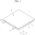
- FIG. 1 illustrates a perspective view of a rechargeable battery according to a first embodiment of the present invention
- FIG. 2 illustrates an exploded perspective view of FIG. 1 .
- a rechargeable battery 1 of the first embodiment includes an electrode assembly 30, a pouch 40 accommodating the electrode assembly 30, and a first film member 10 and a second film member 20 attached to the electrode assembly 30.
- the electrode assembly 30 includes a separator 33, and a first electrode plate 31 and a second electrode plate 32 formed as single sheets on both surfaces of the separator 33. That is, the electrode assembly 30 includes a plurality of the first electrode plate 31 and the second electrode plate 32 alternately disposed between a plurality of separators 33.
- the first electrode plate 31 is a positive electrode plate, and includes a positive electrode active material layer 312 on both surfaces of an electrode current collecting plate 311.
- the first electrode plate 31 includes an electrode tab 313 of an uncoated region protruding to one side.
- the electrode tab 313 is directly drawn out of the pouch 40, or is connected to a lead tab (not shown) and drawn out of the pouch 40.
- the second electrode plate 32 is a negative electrode plate and includes negative electrode active material layers 322 on both surfaces of an electrode current collecting plate 321.
- the second electrode plate 32 includes an electrode tab 323 of an uncoated region protruding to one side.
- the electrode tab 323 is directly drawn out of the pouch 40, or is connected to a lead tab (not shown) and drawn out of the pouch 40.
- the positive electrode plate 31 and the negative electrode plate 32 have a planar area in a first direction (x-axis direction) and a second direction (y-axis direction) crossing each other, and are stacked in a third direction (z-axis direction) crossing the planar area.
- the electrode tabs 313 and 323, that is, the positive electrode tab 313 and the negative electrode tab 323 are spaced apart from each other along the second direction, and are drawn out of the pouch 40 along the first direction.
- the pouch 40 and a cover 41 may be formed to include a polymer sheet 401 that forms an inner surface and acts as electrical insulation and thermal bonding, a nylon sheet 402 that forms an outer surface and acts as protection, and an aluminium sheet 403 providing mechanical strength.
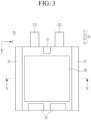
- FIG. 3 illustrates a top plan view of an electrode assembly applied to FIG. 2
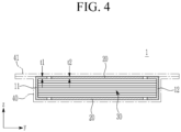
- FIG. 4 illustrates a cross-sectional view taken along line IV-IV of FIG. 3 .
- the first film member 10 generates adhesive force through electrolyte solution and is attached to the electrode assembly 30 in a bent and connected state to both outer surfaces and side surfaces of the outer periphery of the electrode assembly 30.
- the first film member 10 surrounds both outer surfaces and side surfaces of the outer periphery of the electrode assembly 30, thereby controlling the falling flow of the electrode assembly 30, and the first film member 10 prevents the pull-back phenomenon the electrode assembly 30 in which the separator 33 comes out backward even when the falling impact is high.
- the second film member 20 generates adhesive force through electrolyte solution, and is spaced apart from the first film member 10 and attached to one or both of the outer surfaces of the electrode assembly 30.
- the second film member 20 overcomes the decrease in flatness of the first film member 10 and the electrode assembly 30 due to the use of the first film member 10, so it increases the contact area between the first and second film members 10 and 20 and the inner surface of the pouch 40.
- the falling flow of the electrode assembly 30 may be further controlled.
- first film member 10 and the second film member 20 are made of an oriented polystyrene (OPS) film.
- OPS oriented polystyrene
- the first film member 10 is provided on both sides of the first direction (x-axis direction) and both sides of the second direction (y-axis direction), respectively of the electrode assembly 30.
- the first film member 10 includes a pair of first-direction films 11 and 12 stretched and attached (for example, adhered) on both sides of the second direction (y-axis direction) in the first direction (x-axis direction), and a second-direction film 13 stretched and attached in the second direction (y-axis direction) between the pair of first-direction films 11 and 12 on the opposite side of the drawing direction of the positive electrode tab 313 and the negative electrode tab 323.
- the second-direction film 13 may be divided and attached along the second direction (y-axis direction) between the pair of first-direction films 11 and 12.
- the second-direction film 13 may further include a film 14 between tabs attached between the positive electrode tab 313 and the negative electrode tab 323.
- the first-direction films 11 and 12 control and prevent the falling flow in both sides of the second direction (y-axis direction) of the electrode assembly 30, and the second-direction film 13 and the film 14 between the tabs control and prevent the falling flow in both sides of the first direction (x-axis direction) of the electrode assembly 30. Since the first film member 10 has adherence by the electrolyte solution, it may control and prevent the falling flow of the electrode assembly 30.
- the second film member 20 may be attached to one outer surface or both outer surfaces of the electrode assembly 30 between the pair of first-direction films 11 and 12 and at one side of the second-direction film 13.
- the first film member 10 and the second film member 20 are closely adhered to the inner surface of the pouch 40.
- the second film member 20 controls non-uniform flatness between the electrode assembly 30 and the pouch 40 by the first film member 10.
- the second film member 20 improves flatness between the first film member 10 and the surface of the electrode assembly 30, so the contact area between the first and second film members 10 and 20 and the pouch 40 may be improved.
- the first film member 10 has a first thickness t1
- the second film member 20 has a second thickness t2, and they may be attached to both outer surfaces of the electrode assembly 30 (see FIG. 4 ).
- the first and second thicknesses t1 and t2 may be the same.
- the first and second thicknesses t1 and t2 may be 24 ⁇ m to 34 ⁇ m.
- the first film member may have a first thickness
- the second film member may have a second thickness that is twice the first thickness, and they may be attached only to one of both surfaces of the electrode assembly.
- the first thickness t1 may be 24 ⁇ m to 34 ⁇ m
- the second thickness t2 may be 51 ⁇ m to 61 ⁇ m.
- the first film member 10 (11, 12, 13, 14) has a first area A1
- the second film member 20 has a second area A2.
- the both outer surfaces and the side surface of the electrode assembly 30 may not be sufficiently fixed, so that the falling flow may not be sufficiently controlled.
- the first area A1 exceeds 80% of the second area A2, due to the excess of the first area A1 of the first film member 10, it may be difficult to attach the both outer surfaces and the side surface of the electrode assembly 30.
- a change occurs in the entire thickness of the electrode assembly 30 before and after the pressurization formation of the rechargeable battery 1.
- a step change occurs according to the thickness change of the first film member 10 before and after the pressurization formation.
- the thickness change of the second film member 20 before and after pressurization formation absorbs the step change due to the thickness change of the first film member 10 before and after pressurization formation.
- charging and discharging proceeds while applying pressure to a plate against both sides of the rechargeable battery 1 so that the electrode assembly 30 may be uniformly charged and discharged under a flat condition.
- the first electrode plate 31 (positive electrode plate) and the second electrode plate 32 (negative electrode plate) of the rechargeable battery 1 expand and contract. According to this charging and discharging, the electrode assembly 30 expands up to 15%.
- the first film member 10 and the second film member 20 are expanded and controlled while receiving a pressing force. Therefore, the first film member 10 and the second film member 20 have an overall thickness of the same level without a thickness step.
- the thickness of the electrode assembly 30 when the thickness of the electrode assembly 30 is 5.0 mm, the thickness increases to 5.750 mm during pressurization formation charging. That is, the thickness of the electrode assembly 30 becomes thicker by 750 ⁇ m.
- the thickness steps between the first and second film members 10 and 20 are offset by each other, and the first and second film members 10 and 20 have the same level of overall thickness. Accordingly, the flatness of the surface of the rechargeable battery 1 is increased. Since the surface of the rechargeable battery 1 is subjected to a uniform pressure, adhesion between the first electrode plate 31, the separator 33, and the second electrode plate 32 is increased.
- FIG. 5 illustrates a top plan view of an electrode assembly of a rechargeable battery according to a second embodiment of the present disclosure
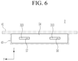
- FIG. 6 illustrates a side view viewed from positive and negative tab sides of FIG. 5 .
- a first film member 50 includes a pair of second-direction films 53 and 54 stretched and attached on both sides of the first direction (x-axis direction) of the electrode assembly 30 in the second direction (y-axis direction), and first-direction films 51 and 52 stretched and attached in the first direction (x-axis direction) between the pair of second-direction films 53 and 54.
- the second direction films 54 on the positive electrode tab 313 and negative electrode tab 323 sides is provided with a pair of through-holes 56 and 57 for drawing out the positive electrode tab 313 and the negative electrode tab 323, respectively.
- the through-holes 56 and 57 allow the second-direction film 54 to be attached even when the positive electrode tab 313 and the negative electrode tab 323 are drawn out. Therefore, the second-direction film 54 stably controls and prevents the falling flow in one side of the first direction (x-axis direction).
- the second-direction films 53 and 54 are entirely attached to both outer surfaces and side surfaces of the electrode assembly 30 in the second direction (y-axis direction).
- the second-direction films 53 and 54 may more effectively control and prevent the falling flow in one side in the first direction (x-axis direction) than the second-direction film 13 and the film 14 between the tabs of the first embodiment.
- the first film member 50 (51, 52, 53, 54) has a first area A21
- the second film member 20 has a second area A22.
- the both outer surfaces and the side surface of the electrode assembly 30 may not be sufficiently fixed, so that the falling flow may not be sufficiently controlled.
- the first area A21 exceeds 110% of the second area A2 due to the excess of the first area A21 of the first film member 50, it may be difficult to attach the both outer surfaces and the side surface of the electrode assembly 30.
- FIG. 7 illustrates a top plan view of an electrode assembly of a rechargeable battery according to a third embodiment of the present disclosure
- FIG. 8 illustrates a cross-sectional view taken along line VIII-VIII of FIG. 7 .
- a rechargeable battery 3 of the third embodiment further includes a binder layer 60 applied to both outer surfaces of the electrode assembly 30.
- the first film member 10 and the second film member 20 are attached on the binder layer 60.
- first film member 10 and the second film member 20 are attached to both outer surfaces and the side surfaces of the outer periphery of the electrode assembly 30, but in the third embodiment, the first film member 10 and the second film member 20 are attached to the side surfaces of the outer periphery and both outer surfaces of the electrode assembly 30 as well as the binder layer 60.
- the first film member 10 and the second film member 20 prevent compressed unevenness and a decrease in adhesive force between the separator 33 and the positive and negative electrode plates 31 and 32 that may occur between both outer surfaces of the electrode assembly 30 and the pouch 40 and the cover 41 due to the binder layer 60 during pressurization formation.
- the binder layer 60 when the binder layer 60 is formed to have a thickness of 5 ⁇ m, a problem occurs due to lack of adhesion with the pouch during pressurization formation, and thus, distribution of falling flow characteristics and distribution of long lifespan characteristics may occur.
- first film member 10 and the second film member 20 are further provided on the binder layer 60, adhesion with the pouch 40 and the cover 41 is secured even during pressurization formation, thereby balancing the falling flow characteristics and long lifespan characteristics.
Landscapes
- Chemical & Material Sciences (AREA)
- Chemical Kinetics & Catalysis (AREA)
- Electrochemistry (AREA)
- General Chemical & Material Sciences (AREA)
- Engineering & Computer Science (AREA)
- Manufacturing & Machinery (AREA)
- Inorganic Chemistry (AREA)
- Secondary Cells (AREA)
- Cell Separators (AREA)
Abstract
An embodiment provides a rechargeable battery including: a stacked type electrode assembly in which a negative electrode plate and a positive electrode plate with electrode tabs are stacked on both outer sides of a separator; a pouch that accommodates the electrode assembly; a first film member that generates adhesive force through an electrolyte solution and is attached to the electrode assembly in a bent and connected state to both outer surfaces and side surfaces of an outer periphery of the electrode assembly; and a second film member that is spaced apart from the first film member to be attached to at least one of the both outer surfaces.
Description
- The present disclosure relates to a rechargeable battery, and more particularly, to a rechargeable battery that may control a falling flow of an electrode assembly.
- A rechargeable battery is a battery that is repeatedly charged and discharged, unlike a primary battery. A small capacity rechargeable battery is used in a small portable electronic device such as a mobile phone, a notebook computer, and a camcorder, while a large capacity rechargeable battery may be used as a power source for driving a motor of a hybrid vehicle and an electric vehicle.
- For example, the rechargeable battery includes an electrode assembly for charging and discharging, a pouch accommodating the electrode assembly, and an electrode tab that electrically connects the electrode assembly and draws it out of the pouch. The electrode assembly includes a winding type in which a negative electrode plate and a positive electrode plate are wound with a separator interposed therebetween, and a stacking type in which a negative electrode plate and a positive electrode plate are stacked with a separator interposed therebetween.
- Pouch cells are mainly used in mobile electronic devices. Therefore, due to negligence in handling or other factors, the pouch cell may frequently fall. An internal short circuit caused by the falling may stop the operation of the electronic device or lead to ignition of the electronic device, causing significant damage to human life or property.
- There is a method of applying tape to solve the falling problem. When the falling impact strength increases, that is, when the weight of the cell increases or the falling height and frequency increase, a pull-back phenomenon occurs in which the separator comes out backward due to the falling of the electrode assembly. Due to the pull-back phenomenon, the electrode substrate or the electrode composite is exposed to the outside, which causes an internal short circuit.
- The present disclosure is to provide a rechargeable battery that may control the falling flow of an electrode assembly. The present disclosure is to provide a rechargeable battery that may prevent the pull-back phenomenon of the electrode assembly even when the falling impact strength is high.
- The present disclosure is to provide a rechargeable battery that may improve flatness between a pouch and an oriented polystyrene (OPS) film while controlling a pull-back phenomenon of a separator by applying the OPS film. The present disclosure is to provide a rechargeable battery that may prevent a problem caused by falling flow by increasing a contact area between a pouch and an OPS film.
- An embodiment provides a rechargeable battery including: a stacked type electrode assembly in which a negative electrode plate and a positive electrode plate with electrode tabs are stacked on both surfaces of a separator; a pouch that accommodates the electrode assembly; a first film member that generates adhesive force through an electrolyte solution and is attached to the electrode assembly in a bent and connected state to both outer surfaces and side surfaces of an outer periphery of the electrode assembly; and a second film member that is spaced apart from the first film member and attached to at least one of the both outer surfaces.
- The first film member and the second film member may be made of an oriented polystyrene (OPS) film.
- The negative electrode plate and the positive plate may have a plane area in first and second directions crossing each other and are stacked in a third direction crossing the plane area; the electrode tab may be drawn out of the pouch along the first direction; and the first film member may be provided on both sides of the first direction and both sides of the second direction, respectively of the electrode assembly.
- The first film member may include a pair of first-direction films that are stretched and adhered on both sides of the second direction in the first direction, and a second-direction film that is stretched and attached in the second direction between the pair of first direction films on a side opposite to a drawing direction of the electrode tab.
- The second-direction film may be divided and attached along the second direction between the pair of first-direction films.
- The second-direction film may further include a film between tabs attached between the electrode tabs.
- The second film member may be attached to at least one of the both outer surfaces, between the pair of first-direction films and on one side of the second-direction film.
- The first film member and the second film member may closely adhere to an inner surface of the pouch.
- The first film member may have a first thickness, and the second film member may have a second thickness that is twice the first thickness and may be attached to one of the both outer surfaces of the electrode assembly.
- The first thickness may be 24 µm to 34 µm, and the second thickness may be 51 µm to 61 µm.
- The first film member may have a first thickness, and the second film member may have the first thickness and may be attached to the both outer surfaces of the electrode assembly.
- The first film member may have a first area A1, the second film member may have a second area A2, and the first area A1 may be 60 to 80% of the second area A2 [A1=(0.6-0.8)*A2].
- The first film member may include a pair of second-direction films that are stretched and adhered on both sides of the first direction of the electrode assembly in the second direction, and a first-direction film that is stretched and attached in the first direction between the pair of second direction films.
- Among the pair of second-direction films, the second direction film on the electrode tab side may be provided with a pair of through-holes through which the electrode tabs are respectively drawn out.
- The pair of second-direction films may be entirely attached to the both outer surfaces and the side surfaces in the second direction.
- The first film member may have a first area A21, the second film member may have a second area A22, and the first area A21 may be 90 to 110% of the second area A22 [A21=(0.9-1.1)*A22].
- The rechargeable battery may further include a binder layer applied to the both outer surfaces of the electrode assembly, wherein the first film member and the second film member may be attached on the binder layer.
- At least some of the above and other features of the invention are set out in the claims.
- It is possible to control the falling flow and pull-back in the electrode assembly by attaching both outer surfaces and side surfaces of the stack-type electrode assembly with the first film member, it is possible to improve the flatness of the first film member and the electrode assembly because the second film member is attached to both outer surfaces or one outer surface of the electrode assembly, and it is possible to increase a contact area between the first and second film members and the pouch.
-
-
FIG. 1 illustrates a perspective view of a rechargeable battery according to a first embodiment of the present invention. -
FIG. 2 illustrates an exploded perspective view ofFIG. 1 . -
FIG. 3 illustrates a top plan view of an electrode assembly applied toFIG. 2 . -
FIG. 4 illustrates a cross-sectional view taken along line IV-IV ofFIG. 3 . -
FIG. 5 illustrates a top plan view of an electrode assembly of a rechargeable battery according to a second embodiment of the present disclosure. -
FIG. 6 illustrates a side view viewed from positive and negative tab sides ofFIG. 5 . -
FIG. 7 illustrates a top plan view of an electrode assembly of a rechargeable battery according to a third embodiment of the present disclosure. -
FIG. 8 illustrates a cross-sectional view taken along line VIII-VIII ofFIG. 7 . - The present disclosure will be described more fully hereinafter with reference to the accompanying drawings, in which embodiments of the invention are shown. As those skilled in the art would realize, the described embodiments may be modified in various different ways, all without departing from the scope of the present disclosure. The drawings and description are to be regarded as illustrative in nature and not restrictive. Like reference numerals designate like elements throughout the specification.
-
FIG. 1 illustrates a perspective view of a rechargeable battery according to a first embodiment of the present invention, andFIG. 2 illustrates an exploded perspective view ofFIG. 1 . - Referring to
FIG. 1 andFIG. 2 , arechargeable battery 1 of the first embodiment includes anelectrode assembly 30, apouch 40 accommodating theelectrode assembly 30, and afirst film member 10 and asecond film member 20 attached to theelectrode assembly 30. - The
electrode assembly 30 includes aseparator 33, and afirst electrode plate 31 and asecond electrode plate 32 formed as single sheets on both surfaces of theseparator 33. That is, theelectrode assembly 30 includes a plurality of thefirst electrode plate 31 and thesecond electrode plate 32 alternately disposed between a plurality ofseparators 33. - As an example, the
first electrode plate 31 is a positive electrode plate, and includes a positive electrode active material layer 312 on both surfaces of an electrode current collecting plate 311. Thefirst electrode plate 31 includes anelectrode tab 313 of an uncoated region protruding to one side. Theelectrode tab 313 is directly drawn out of thepouch 40, or is connected to a lead tab (not shown) and drawn out of thepouch 40. - The
second electrode plate 32 is a negative electrode plate and includes negative electrodeactive material layers 322 on both surfaces of an electrodecurrent collecting plate 321. Thesecond electrode plate 32 includes anelectrode tab 323 of an uncoated region protruding to one side. Theelectrode tab 323 is directly drawn out of thepouch 40, or is connected to a lead tab (not shown) and drawn out of thepouch 40. - The
positive electrode plate 31 and thenegative electrode plate 32 have a planar area in a first direction (x-axis direction) and a second direction (y-axis direction) crossing each other, and are stacked in a third direction (z-axis direction) crossing the planar area. Theelectrode tabs positive electrode tab 313 and thenegative electrode tab 323 are spaced apart from each other along the second direction, and are drawn out of thepouch 40 along the first direction. - For example, the
pouch 40 and acover 41 may be formed to include a polymer sheet 401 that forms an inner surface and acts as electrical insulation and thermal bonding, anylon sheet 402 that forms an outer surface and acts as protection, and an aluminium sheet 403 providing mechanical strength. -
FIG. 3 illustrates a top plan view of an electrode assembly applied toFIG. 2 , andFIG. 4 illustrates a cross-sectional view taken along line IV-IV ofFIG. 3 . - Referring to
FIG. 2 to FIG. 4 , thefirst film member 10 generates adhesive force through electrolyte solution and is attached to theelectrode assembly 30 in a bent and connected state to both outer surfaces and side surfaces of the outer periphery of theelectrode assembly 30. - The
first film member 10 surrounds both outer surfaces and side surfaces of the outer periphery of theelectrode assembly 30, thereby controlling the falling flow of theelectrode assembly 30, and thefirst film member 10 prevents the pull-back phenomenon theelectrode assembly 30 in which theseparator 33 comes out backward even when the falling impact is high. - The
second film member 20 generates adhesive force through electrolyte solution, and is spaced apart from thefirst film member 10 and attached to one or both of the outer surfaces of theelectrode assembly 30. Thesecond film member 20 overcomes the decrease in flatness of thefirst film member 10 and theelectrode assembly 30 due to the use of thefirst film member 10, so it increases the contact area between the first andsecond film members pouch 40. As described above, since the first andsecond film members electrode assembly 30 come into contact with the inner surface of thepouch 40 in a large area, the falling flow of theelectrode assembly 30 may be further controlled. - For example, the
first film member 10 and thesecond film member 20 are made of an oriented polystyrene (OPS) film. Thefirst film member 10 and thesecond film member 20 generate adhesive force through the electrolyte solution accommodated in thepouch 40. - The
first film member 10 is provided on both sides of the first direction (x-axis direction) and both sides of the second direction (y-axis direction), respectively of theelectrode assembly 30. As an example, thefirst film member 10 includes a pair of first-direction films direction film 13 stretched and attached in the second direction (y-axis direction) between the pair of first-direction films positive electrode tab 313 and thenegative electrode tab 323. - The second-
direction film 13 may be divided and attached along the second direction (y-axis direction) between the pair of first-direction films direction film 13 may further include afilm 14 between tabs attached between thepositive electrode tab 313 and thenegative electrode tab 323. - Among the
first film member 10, the first-direction films electrode assembly 30, and the second-direction film 13 and thefilm 14 between the tabs control and prevent the falling flow in both sides of the first direction (x-axis direction) of theelectrode assembly 30. Since thefirst film member 10 has adherence by the electrolyte solution, it may control and prevent the falling flow of theelectrode assembly 30. - The
second film member 20 may be attached to one outer surface or both outer surfaces of theelectrode assembly 30 between the pair of first-direction films direction film 13. Thefirst film member 10 and thesecond film member 20 are closely adhered to the inner surface of thepouch 40. - Accordingly, the
second film member 20 controls non-uniform flatness between theelectrode assembly 30 and thepouch 40 by thefirst film member 10. Thesecond film member 20 improves flatness between thefirst film member 10 and the surface of theelectrode assembly 30, so the contact area between the first andsecond film members pouch 40 may be improved. - The
first film member 10 has a first thickness t1, and thesecond film member 20 has a second thickness t2, and they may be attached to both outer surfaces of the electrode assembly 30 (seeFIG. 4 ). In this case, the first and second thicknesses t1 and t2 may be the same. In this case, the first and second thicknesses t1 and t2 may be 24 µm to 34 µm. - Although not separately shown, the first film member may have a first thickness, and the second film member may have a second thickness that is twice the first thickness, and they may be attached only to one of both surfaces of the electrode assembly. In this case, the first thickness t1 may be 24 µm to 34 µm, and the second thickness t2 may be 51 µm to 61 µm.
- Referring back to
FIG. 3 , the first film member 10 (11, 12, 13, 14) has a first area A1, and thesecond film member 20 has a second area A2. The first area A1 may be 60 to 80% of the second area A2 [A1 =(0.6-0.8)*A2]. - When the first area A1 is less than 60% of the second area A2, due to the lack of the first area A1 of the
first film member 10, the both outer surfaces and the side surface of theelectrode assembly 30 may not be sufficiently fixed, so that the falling flow may not be sufficiently controlled. When the first area A1 exceeds 80% of the second area A2, due to the excess of the first area A1 of thefirst film member 10, it may be difficult to attach the both outer surfaces and the side surface of theelectrode assembly 30. - A change occurs in the entire thickness of the
electrode assembly 30 before and after the pressurization formation of therechargeable battery 1. A step change occurs according to the thickness change of thefirst film member 10 before and after the pressurization formation. The thickness change of thesecond film member 20 before and after pressurization formation absorbs the step change due to the thickness change of thefirst film member 10 before and after pressurization formation. - In the pressurization formation, charging and discharging proceeds while applying pressure to a plate against both sides of the
rechargeable battery 1 so that theelectrode assembly 30 may be uniformly charged and discharged under a flat condition. - That is, during the pressurization formation, the first electrode plate 31 (positive electrode plate) and the second electrode plate 32 (negative electrode plate) of the
rechargeable battery 1 expand and contract. According to this charging and discharging, theelectrode assembly 30 expands up to 15%. - In this case, the
first film member 10 and thesecond film member 20 are expanded and controlled while receiving a pressing force. Therefore, thefirst film member 10 and thesecond film member 20 have an overall thickness of the same level without a thickness step. - For example, when the thickness of the
electrode assembly 30 is 5.0 mm, the thickness increases to 5.750 mm during pressurization formation charging. That is, the thickness of theelectrode assembly 30 becomes thicker by 750 µm. - In this case, the thickness steps between the first and
second film members second film members rechargeable battery 1 is increased. Since the surface of therechargeable battery 1 is subjected to a uniform pressure, adhesion between thefirst electrode plate 31, theseparator 33, and thesecond electrode plate 32 is increased. - Hereinafter, various embodiments of the present disclosure will be described. Descriptions of configurations that are the same as the first embodiment or the configuration described above will be omitted, and descriptions of other configurations will be provided.
-
FIG. 5 illustrates a top plan view of an electrode assembly of a rechargeable battery according to a second embodiment of the present disclosure, andFIG. 6 illustrates a side view viewed from positive and negative tab sides ofFIG. 5 . - Referring to
FIG. 5 andFIG. 6 , in arechargeable battery 2 of the second embodiment, afirst film member 50 includes a pair of second-direction films electrode assembly 30 in the second direction (y-axis direction), and first-direction films direction films - Among the pair of second-
direction films second direction films 54 on thepositive electrode tab 313 andnegative electrode tab 323 sides is provided with a pair of through-holes positive electrode tab 313 and thenegative electrode tab 323, respectively. The through-holes direction film 54 to be attached even when thepositive electrode tab 313 and thenegative electrode tab 323 are drawn out. Therefore, the second-direction film 54 stably controls and prevents the falling flow in one side of the first direction (x-axis direction). - The second-
direction films electrode assembly 30 in the second direction (y-axis direction). The second-direction films direction film 13 and thefilm 14 between the tabs of the first embodiment. - Referring back to
FIG. 5 , the first film member 50 (51, 52, 53, 54) has a first area A21, and thesecond film member 20 has a second area A22. The first area A21 may be 90 to 110% of the second area A22 [A21 =(0.9-1.1)*A22]. - When the first area A21 is less than 90% of the second area A22, due to the lack of the first area A21 of the
first film member 50, the both outer surfaces and the side surface of theelectrode assembly 30 may not be sufficiently fixed, so that the falling flow may not be sufficiently controlled. When the first area A21 exceeds 110% of the second area A2, due to the excess of the first area A21 of thefirst film member 50, it may be difficult to attach the both outer surfaces and the side surface of theelectrode assembly 30. -
FIG. 7 illustrates a top plan view of an electrode assembly of a rechargeable battery according to a third embodiment of the present disclosure, andFIG. 8 illustrates a cross-sectional view taken along line VIII-VIII ofFIG. 7 . - Referring to
FIG. 7 andFIG. 8 , a rechargeable battery 3 of the third embodiment further includes abinder layer 60 applied to both outer surfaces of theelectrode assembly 30. Thefirst film member 10 and thesecond film member 20 are attached on thebinder layer 60. - In the first embodiment, the
first film member 10 and thesecond film member 20 are attached to both outer surfaces and the side surfaces of the outer periphery of theelectrode assembly 30, but in the third embodiment, thefirst film member 10 and thesecond film member 20 are attached to the side surfaces of the outer periphery and both outer surfaces of theelectrode assembly 30 as well as thebinder layer 60. - The
first film member 10 and thesecond film member 20 prevent compressed unevenness and a decrease in adhesive force between theseparator 33 and the positive andnegative electrode plates electrode assembly 30 and thepouch 40 and thecover 41 due to thebinder layer 60 during pressurization formation. - As an example, when the
binder layer 60 is formed to have a thickness of 5 µm, a problem occurs due to lack of adhesion with the pouch during pressurization formation, and thus, distribution of falling flow characteristics and distribution of long lifespan characteristics may occur. - However, since the
first film member 10 and thesecond film member 20 are further provided on thebinder layer 60, adhesion with thepouch 40 and thecover 41 is secured even during pressurization formation, thereby balancing the falling flow characteristics and long lifespan characteristics. - While this disclosure has been described in connection with what is presently considered to be practical embodiments, it is to be understood that the disclosure is not limited to the disclosed embodiments, but, on the contrary, is intended to cover various modifications and equivalent arrangements included within the scope of the appended claims.
<Description of Symbols> 1, 2, 3: rechargeable battery 10: first film member 11, 12: first-direction film 13: second-direction film 14: film between tabs 20: second film member 30: electrode assembly 31: first electrode plate (positive electrode plate) 32: second electrode plate (negative electrode plate) 33: separator 40: pouch 41: cover 50: first film member 51, 52: first- direction film 53, 54: second-direction film 60: binder layer 311: electrode current collecting plate 312: positive electrode active material layer 313: electrode tab (positive electrode tab) 321: electrode current collecting plate 322: negative active material layer 323: electrode tab (negative electrode tab) 401: polymer sheet 402: nylon sheet 403: aluminium sheet A1, A21: first area A2, A22: second area t1: first thickness t2: second thickness
Claims (15)
- A rechargeable battery comprising:a stacked type electrode assembly in which a negative electrode plate and a positive electrode plate with electrode tabs are stacked on both surfaces of a separator;a pouch that accommodates the electrode assembly;a first film member that generates adhesive force through an electrolyte solution and is attached to the electrode assembly in a bent and connected state to both outer surfaces and side surfaces of an outer periphery of the electrode assembly; anda second film member that is spaced apart from the first film member and attached to at least one of the both outer surfaces.
- The rechargeable battery as claimed in claim 1, wherein
the first film member and the second film member are made of an oriented polystyrene film. - The rechargeable battery as claimed in claim 1 or claim 2, whereinthe negative electrode plate and the positive plate have a plane area in first and second directions crossing each other and are stacked in a third direction crossing the plane area;the electrode tab is drawn out of the pouch along the first direction; andthe first film member is provided on both sides of the first direction and both sides of the second direction, respectively of the electrode assembly.
- The rechargeable battery as claimed in claim 3, whereinthe first film member includesa pair of first-direction films that are stretched and adhered on both sides of the second direction in the first direction, anda second-direction film that is stretched and attached in the second direction between the pair of first direction films on a side opposite to a drawing direction of the electrode tab.
- The rechargeable battery as claimed in claim 4, wherein
the second-direction film is divided and attached along the second direction between the pair of first-direction films. - The rechargeable battery as claimed in claim 5, wherein
the second-direction film further includes a film between tabs attached between the electrode tabs. - The rechargeable battery as claimed in any one of claims 4 to 6, whereinthe second film member is attached to at least one of the both outer surfaces, between the pair of first-direction films and on one side of the second-direction film, optionally whereinthe first film member and the second film member closely adhere to an inner surface of the pouch.
- The rechargeable battery as claimed in any one of claims 1 to 7, whereinthe first film member has a first thickness, andthe second film member has a second thickness that is twice the first thickness and is attached to one of the both outer surface of the electrode assembly, optionally whereinthe first thickness is 24 µm to 34 µm, and the second thickness is 51 µm to 61 µm.
- The rechargeable battery as claimed in any one of claims 1 to 7, whereinthe first film member has a first thickness, andthe second film member has the first thickness and is attached to the both outer surfaces of the electrode assembly.
- The rechargeable battery as claimed in any one of claims 9 to 11, whereinthe first film member has a first area A1,the second film member has a second area A2, andthe first area A1 is 60 to 80% of the second area A2 [A1 =(0.6-0.8)*A2].
- The rechargeable battery as claimed in claim 3, whereinthe first film member includesa pair of second-direction films that are stretched and adhered on both sides of the first direction of the electrode assembly in the second direction, anda first-direction film that is stretched and attached in the first direction between the pair of second direction films.
- The rechargeable battery as claimed in claim 11, wherein
among the pair of second-direction films, the second direction film on the electrode tab side is provided with a pair of through-holes through which the electrode tabs are respectively drawn out. - The rechargeable battery as claimed in claim 12, wherein
the pair of second-direction films are attached to the both outer surfaces and the side surfaces entirely in the second direction. - The rechargeable battery as claimed in any one of claims 11 to 13, whereinthe first film member has a first area A21,the second film member has a second area A22, andthe first area A21 is 90 to 110% of the second area A22 [A21=(0.9-1.1)*A22].
- The rechargeable battery as claimed in any one of claims 1 to 14, further comprisinga binder layer applied to the both outer surfaces of the electrode assembly,wherein the first film member and the second film member are attached on the binder layer.
Applications Claiming Priority (1)
| Application Number | Priority Date | Filing Date | Title |
|---|---|---|---|
| KR1020230016975A KR20240124114A (en) | 2023-02-08 | 2023-02-08 | Rechargeable battery |
Publications (1)
| Publication Number | Publication Date |
|---|---|
| EP4415090A1 true EP4415090A1 (en) | 2024-08-14 |
Family
ID=88068824
Family Applications (1)
| Application Number | Title | Priority Date | Filing Date |
|---|---|---|---|
| EP23197369.4A Pending EP4415090A1 (en) | 2023-02-08 | 2023-09-14 | Rechargeable battery |
Country Status (4)
| Country | Link |
|---|---|
| US (1) | US20240266643A1 (en) |
| EP (1) | EP4415090A1 (en) |
| KR (1) | KR20240124114A (en) |
| CN (1) | CN118472509A (en) |
Citations (3)
| Publication number | Priority date | Publication date | Assignee | Title |
|---|---|---|---|---|
| EP3142182B1 (en) * | 2015-04-29 | 2018-10-03 | LG Chem, Ltd. | Pouch-type secondary battery and manufacturing method therefor |
| KR20220010792A (en) * | 2020-07-20 | 2022-01-27 | 주식회사 엘지에너지솔루션 | Pouch type secondary battery having moving prevention part and manufacturing thereof |
| WO2022204943A1 (en) * | 2021-03-30 | 2022-10-06 | 宁德新能源科技有限公司 | Battery cell and battery |
-
2023
- 2023-02-08 KR KR1020230016975A patent/KR20240124114A/en active Pending
- 2023-09-14 EP EP23197369.4A patent/EP4415090A1/en active Pending
- 2023-09-21 CN CN202311222196.4A patent/CN118472509A/en active Pending
- 2023-10-11 US US18/378,716 patent/US20240266643A1/en active Pending
Patent Citations (3)
| Publication number | Priority date | Publication date | Assignee | Title |
|---|---|---|---|---|
| EP3142182B1 (en) * | 2015-04-29 | 2018-10-03 | LG Chem, Ltd. | Pouch-type secondary battery and manufacturing method therefor |
| KR20220010792A (en) * | 2020-07-20 | 2022-01-27 | 주식회사 엘지에너지솔루션 | Pouch type secondary battery having moving prevention part and manufacturing thereof |
| WO2022204943A1 (en) * | 2021-03-30 | 2022-10-06 | 宁德新能源科技有限公司 | Battery cell and battery |
Also Published As
| Publication number | Publication date |
|---|---|
| KR20240124114A (en) | 2024-08-16 |
| US20240266643A1 (en) | 2024-08-08 |
| CN118472509A (en) | 2024-08-09 |
Similar Documents
| Publication | Publication Date | Title |
|---|---|---|
| CN100411239C (en) | Battery cell and lithium secondary battery using the same | |
| JP6788107B2 (en) | Manufacturing method of electrode unit for battery cell and electrode unit | |
| US11302902B2 (en) | Method for manufacturing an electrode assembly for a battery cell and battery cell | |
| CN112119525B (en) | Secondary battery and method for manufacturing the same | |
| US20150287966A1 (en) | Electrode assembly and secondary battery having the same | |
| CN111630699B (en) | Secondary battery | |
| US20250140965A1 (en) | Easy-to-disassemble battery pack | |
| KR102278445B1 (en) | Electrode assembly, and rechargeable battery | |
| US11557819B2 (en) | Battery pack and label attaching method thereof | |
| KR100876253B1 (en) | Polymer battery pack | |
| US6524738B1 (en) | Lithium battery incorporating protective positive temperature coefficient material | |
| US20230268627A1 (en) | Method for Manufacturing Secondary Battery and Secondary Battery | |
| CN222966277U (en) | Battery pack | |
| EP4415090A1 (en) | Rechargeable battery | |
| EP4531191A1 (en) | Rechargeable battery | |
| KR20190055994A (en) | Secondary battery | |
| EP4191754A1 (en) | Secondary battery | |
| CN113644387B (en) | Battery | |
| KR20120000855A (en) | Secondary battery | |
| US20260088462A1 (en) | Secondary battery electrode and electrode assemblly including secondary battery electrode | |
| US20250329832A1 (en) | Battery case, battery including same, and method of manufacturing battery case | |
| KR102888921B1 (en) | Rechargeable battery manufacturing method and rechargeable battery | |
| EP4525113A2 (en) | Rechargeable battery | |
| KR20260013757A (en) | Battery cell and method of manufacturing the same | |
| CN120752788A (en) | Battery cell and battery module including the same |
Legal Events
| Date | Code | Title | Description |
|---|---|---|---|
| PUAI | Public reference made under article 153(3) epc to a published international application that has entered the european phase |
Free format text: ORIGINAL CODE: 0009012 |
|
| STAA | Information on the status of an ep patent application or granted ep patent |
Free format text: STATUS: REQUEST FOR EXAMINATION WAS MADE |
|
| 17P | Request for examination filed |
Effective date: 20230914 |
|
| AK | Designated contracting states |
Kind code of ref document: A1 Designated state(s): AL AT BE BG CH CY CZ DE DK EE ES FI FR GB GR HR HU IE IS IT LI LT LU LV MC ME MK MT NL NO PL PT RO RS SE SI SK SM TR |