EP4415080A1 - Power storage device - Google Patents
Power storage device Download PDFInfo
- Publication number
- EP4415080A1 EP4415080A1 EP24153494.0A EP24153494A EP4415080A1 EP 4415080 A1 EP4415080 A1 EP 4415080A1 EP 24153494 A EP24153494 A EP 24153494A EP 4415080 A1 EP4415080 A1 EP 4415080A1
- Authority
- EP
- European Patent Office
- Prior art keywords
- conductive member
- electrode assembly
- current collector
- collector terminal
- electrically conducting
- Prior art date
- Legal status (The legal status is an assumption and is not a legal conclusion. Google has not performed a legal analysis and makes no representation as to the accuracy of the status listed.)
- Pending
Links
Images



Classifications
-
- H—ELECTRICITY
- H01—ELECTRIC ELEMENTS
- H01M—PROCESSES OR MEANS, e.g. BATTERIES, FOR THE DIRECT CONVERSION OF CHEMICAL ENERGY INTO ELECTRICAL ENERGY
- H01M50/00—Constructional details or processes of manufacture of the non-active parts of electrochemical cells other than fuel cells, e.g. hybrid cells
- H01M50/20—Mountings; Secondary casings or frames; Racks, modules or packs; Suspension devices; Shock absorbers; Transport or carrying devices; Holders
- H01M50/296—Mountings; Secondary casings or frames; Racks, modules or packs; Suspension devices; Shock absorbers; Transport or carrying devices; Holders characterised by terminals of battery packs
-
- H—ELECTRICITY
- H01—ELECTRIC ELEMENTS
- H01M—PROCESSES OR MEANS, e.g. BATTERIES, FOR THE DIRECT CONVERSION OF CHEMICAL ENERGY INTO ELECTRICAL ENERGY
- H01M4/00—Electrodes
- H01M4/02—Electrodes composed of, or comprising, active material
- H01M4/64—Carriers or collectors
- H01M4/70—Carriers or collectors characterised by shape or form
- H01M4/78—Shapes other than plane or cylindrical, e.g. helical
-
- H—ELECTRICITY
- H01—ELECTRIC ELEMENTS
- H01M—PROCESSES OR MEANS, e.g. BATTERIES, FOR THE DIRECT CONVERSION OF CHEMICAL ENERGY INTO ELECTRICAL ENERGY
- H01M50/00—Constructional details or processes of manufacture of the non-active parts of electrochemical cells other than fuel cells, e.g. hybrid cells
- H01M50/50—Current conducting connections for cells or batteries
- H01M50/572—Means for preventing undesired use or discharge
-
- H—ELECTRICITY
- H01—ELECTRIC ELEMENTS
- H01M—PROCESSES OR MEANS, e.g. BATTERIES, FOR THE DIRECT CONVERSION OF CHEMICAL ENERGY INTO ELECTRICAL ENERGY
- H01M10/00—Secondary cells; Manufacture thereof
- H01M10/04—Construction or manufacture in general
- H01M10/0413—Large-sized flat cells or batteries for motive or stationary systems with plate-like electrodes
-
- H—ELECTRICITY
- H01—ELECTRIC ELEMENTS
- H01M—PROCESSES OR MEANS, e.g. BATTERIES, FOR THE DIRECT CONVERSION OF CHEMICAL ENERGY INTO ELECTRICAL ENERGY
- H01M10/00—Secondary cells; Manufacture thereof
- H01M10/04—Construction or manufacture in general
- H01M10/0413—Large-sized flat cells or batteries for motive or stationary systems with plate-like electrodes
- H01M10/0418—Large-sized flat cells or batteries for motive or stationary systems with plate-like electrodes with bipolar electrodes
-
- H—ELECTRICITY
- H01—ELECTRIC ELEMENTS
- H01M—PROCESSES OR MEANS, e.g. BATTERIES, FOR THE DIRECT CONVERSION OF CHEMICAL ENERGY INTO ELECTRICAL ENERGY
- H01M4/00—Electrodes
- H01M4/02—Electrodes composed of, or comprising, active material
- H01M4/64—Carriers or collectors
- H01M4/66—Selection of materials
- H01M4/665—Composites
- H01M4/667—Composites in the form of layers, e.g. coatings
-
- H—ELECTRICITY
- H01—ELECTRIC ELEMENTS
- H01M—PROCESSES OR MEANS, e.g. BATTERIES, FOR THE DIRECT CONVERSION OF CHEMICAL ENERGY INTO ELECTRICAL ENERGY
- H01M50/00—Constructional details or processes of manufacture of the non-active parts of electrochemical cells other than fuel cells, e.g. hybrid cells
- H01M50/20—Mountings; Secondary casings or frames; Racks, modules or packs; Suspension devices; Shock absorbers; Transport or carrying devices; Holders
- H01M50/298—Mountings; Secondary casings or frames; Racks, modules or packs; Suspension devices; Shock absorbers; Transport or carrying devices; Holders characterised by the wiring of battery packs
-
- H—ELECTRICITY
- H01—ELECTRIC ELEMENTS
- H01M—PROCESSES OR MEANS, e.g. BATTERIES, FOR THE DIRECT CONVERSION OF CHEMICAL ENERGY INTO ELECTRICAL ENERGY
- H01M50/00—Constructional details or processes of manufacture of the non-active parts of electrochemical cells other than fuel cells, e.g. hybrid cells
- H01M50/50—Current conducting connections for cells or batteries
- H01M50/528—Fixed electrical connections, i.e. not intended for disconnection
-
- H—ELECTRICITY
- H01—ELECTRIC ELEMENTS
- H01M—PROCESSES OR MEANS, e.g. BATTERIES, FOR THE DIRECT CONVERSION OF CHEMICAL ENERGY INTO ELECTRICAL ENERGY
- H01M50/00—Constructional details or processes of manufacture of the non-active parts of electrochemical cells other than fuel cells, e.g. hybrid cells
- H01M50/50—Current conducting connections for cells or batteries
- H01M50/531—Electrode connections inside a battery casing
-
- H—ELECTRICITY
- H01—ELECTRIC ELEMENTS
- H01M—PROCESSES OR MEANS, e.g. BATTERIES, FOR THE DIRECT CONVERSION OF CHEMICAL ENERGY INTO ELECTRICAL ENERGY
- H01M50/00—Constructional details or processes of manufacture of the non-active parts of electrochemical cells other than fuel cells, e.g. hybrid cells
- H01M50/50—Current conducting connections for cells or batteries
- H01M50/531—Electrode connections inside a battery casing
- H01M50/54—Connection of several leads or tabs of plate-like electrode stacks, e.g. electrode pole straps or bridges
-
- H—ELECTRICITY
- H01—ELECTRIC ELEMENTS
- H01M—PROCESSES OR MEANS, e.g. BATTERIES, FOR THE DIRECT CONVERSION OF CHEMICAL ENERGY INTO ELECTRICAL ENERGY
- H01M50/00—Constructional details or processes of manufacture of the non-active parts of electrochemical cells other than fuel cells, e.g. hybrid cells
- H01M50/50—Current conducting connections for cells or batteries
- H01M50/543—Terminals
- H01M50/547—Terminals characterised by the disposition of the terminals on the cells
- H01M50/55—Terminals characterised by the disposition of the terminals on the cells on the same side of the cell
-
- H—ELECTRICITY
- H01—ELECTRIC ELEMENTS
- H01M—PROCESSES OR MEANS, e.g. BATTERIES, FOR THE DIRECT CONVERSION OF CHEMICAL ENERGY INTO ELECTRICAL ENERGY
- H01M50/00—Constructional details or processes of manufacture of the non-active parts of electrochemical cells other than fuel cells, e.g. hybrid cells
- H01M50/50—Current conducting connections for cells or batteries
- H01M50/543—Terminals
- H01M50/552—Terminals characterised by their shape
- H01M50/553—Terminals adapted for prismatic, pouch or rectangular cells
-
- H—ELECTRICITY
- H01—ELECTRIC ELEMENTS
- H01M—PROCESSES OR MEANS, e.g. BATTERIES, FOR THE DIRECT CONVERSION OF CHEMICAL ENERGY INTO ELECTRICAL ENERGY
- H01M50/00—Constructional details or processes of manufacture of the non-active parts of electrochemical cells other than fuel cells, e.g. hybrid cells
- H01M50/50—Current conducting connections for cells or batteries
- H01M50/572—Means for preventing undesired use or discharge
- H01M50/584—Means for preventing undesired use or discharge for preventing incorrect connections inside or outside the batteries
- H01M50/59—Means for preventing undesired use or discharge for preventing incorrect connections inside or outside the batteries characterised by the protection means
- H01M50/593—Spacers; Insulating plates
-
- Y—GENERAL TAGGING OF NEW TECHNOLOGICAL DEVELOPMENTS; GENERAL TAGGING OF CROSS-SECTIONAL TECHNOLOGIES SPANNING OVER SEVERAL SECTIONS OF THE IPC; TECHNICAL SUBJECTS COVERED BY FORMER USPC CROSS-REFERENCE ART COLLECTIONS [XRACs] AND DIGESTS
- Y02—TECHNOLOGIES OR APPLICATIONS FOR MITIGATION OR ADAPTATION AGAINST CLIMATE CHANGE
- Y02E—REDUCTION OF GREENHOUSE GAS [GHG] EMISSIONS, RELATED TO ENERGY GENERATION, TRANSMISSION OR DISTRIBUTION
- Y02E60/00—Enabling technologies; Technologies with a potential or indirect contribution to GHG emissions mitigation
- Y02E60/10—Energy storage using batteries
Definitions
- the present disclosure relates to a power storage device.
- Japanese Patent No. 7137703 discloses a power storage device including a plurality of power storage modules (bipolar batteries) stacked on top of each other, and a pair of conductive plates arranged on both sides of a corresponding one of the plurality of power storage modules in a stacking direction. A positive electrode terminal is connected to one conductive plate, and a negative electrode terminal is connected to the other conductive plate.
- An object of the present disclosure is to provide a power storage device that can suppress concentration of a current on a portion of a conductive member in the vicinity of a current collector terminal.
- a power storage device includes: an electrode assembly formed by stacking a plurality of electrodes; and a conductive member that is in contact with the electrode assembly, wherein the conductive member includes: a conductive member body that overlaps with the electrode assembly in a stacking direction of the plurality of electrodes; and a current collector terminal that is continuous to the conductive member body, the conductive member body includes: an insulated region insulated from the electrode assembly; and an electrically conducting region, at least a part of the electrically conducting region being electrically connected to the electrode assembly, and a distance between the current collector terminal and the electrically conducting region is greater than a distance between the current collector terminal and the insulated region.
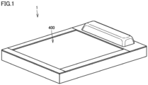
- Fig. 1 is a perspective view schematically showing a power storage device according to an embodiment of the present disclosure.
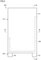
- Fig. 2 is a plan view of the power storage device.
- Fig. 3 is a cross-sectional view taken along line III-III in Fig. 2 .
- Fig. 4 is a cross-sectional view taken along line IV-IV in Fig. 2 .
- a power storage device 1 includes a plurality of electrode assemblies 100, a cooler 200, a current-carrying plate 300, a pair of conductive members 400, and an insulating member 500.
- the plurality of electrode assemblies 100 are stacked on top of each other.
- the plurality of electrode assemblies 100 include four electrode assemblies 100.
- the number of electrode assemblies 100 is not limited to four.
- Each electrode assembly 100 is formed to have a rectangular outer shape in a plan view.
- Each electrode assembly 100 is formed by stacking a plurality of electrodes.
- Bipolar electrode 110 includes a current-collecting foil 111, a positive electrode active material layer 112 provided on one surface of current-collecting foil 111, and a negative electrode active material layer 113 provided on the other surface of current-collecting foil 111.
- electrode assembly 100 is formed by alternately stacking bipolar electrode 110 and a separator 130.
- each electrode may be implemented by a monopolar electrode 120 shown in Fig. 6 .
- Positive electrode monopolar electrode 120 or negative electrode monopolar electrode 120 includes a current-collecting foil 121, and an active material layer 122 provided on current-collecting foil 121.
- electrode assembly 100 is formed by stacking positive electrode monopolar electrode 120 and negative electrode monopolar electrode 120 with separator 130 interposed therebetween.
- each electrode assembly 100 in a stacking direction of the plurality of electrodes is formed by the electrode.
- Cooler 200 is provided between a pair of electrode assemblies 100 that are adjacent to each other. Cooler 200 brings the pair of electrode assemblies 100 into conduction.
- cooler 200 is arranged between electrode assembly 100 arranged on the outermost side of the plurality of electrode assemblies 100 in a stacking direction (vertical direction in Figs. 3 and 4 ) of the plurality of electrode assemblies 100 and electrode assembly 100 adjacent to that electrode assembly 100.
- a flow path through which a coolant (such as water) can flow is provided in cooler 200.
- Current-carrying plate 300 is arranged between second electrode assembly 100 from the bottom and third electrode assembly 100 from the bottom.
- Current-carrying plate 300 may be formed to have a flat plate shape.
- Each conductive member 400 is in contact with electrode assembly 100. As shown in Figs. 2 to 4 , the pair of conductive members 400 include an upper conductive member 410 arranged on uppermost electrode assembly 100, and a lower conductive member 420 arranged under lowermost electrode assembly 100. Each of conductive members 410 and 420 forms a current collector member.
- Upper conductive member 410 includes a conductive member body 411 and a current collector terminal 412.
- Conductive member body 411 overlaps with electrode assembly 100 in the stacking direction. As shown in Figs. 3 and 4 , a recess that is recessed outwardly in the stacking direction is formed in a central portion of conductive member body 411. The central portion of conductive member body 411 may be formed by a through hole. Conductive member body 411 is formed to have a rectangular outer shape in a plan view.
- Current collector terminal 412 is continuous to conductive member body 411. Current collector terminal 412 protrudes outwardly in a direction orthogonal to the stacking direction.
- Lower conductive member 420 includes a conductive member body 421 having the same configuration as that of conductive member body 411 of upper conductive member 410, and a current collector terminal 422 that is continuous to conductive member body 421. As shown in Fig. 2 , current collector terminal 422 is provided at such a position that current collector terminal 422 does not overlap with current collector terminal 412 in a plan view. However, current collector terminal 422 may be provided at such a position that at least a part of current collector terminal 422 overlaps with current collector terminal 412 in a plan view.
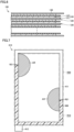
- conductive member body 411 of upper conductive member 410 and conductive member body 421 of lower conductive member 420 have the same configuration, conductive member body 411 will be described below. As shown in Fig. 7 , conductive member body 411 includes an insulated region R10 and an electrically conducting region R20.
- Insulated region R10 is a region insulated from electrode assembly 100. In the present embodiment, as shown in Figs. 3 and 4 , insulating member 500 is arranged between insulated region R10 and electrode assembly 100. Insulated region R10 is adjacent to current collector terminal 412.
- Electrically conducting region R20 is a region where at least a part of electrically conducting region R20 is electrically connected to electrode assembly 100. At least a part of electrically conducting region R20 is in contact with electrode assembly 100 directly or with a not-shown conductive material (such as a conductive adhesive) interposed therebetween. A distance between current collector terminal 412 and electrically conducting region R20 is greater than a distance between current collector terminal 412 and insulated region R10. Electrically conducting region R20 is adjacent to insulated region R10.
- Electrically conducting region R20 includes a plurality of electrically conducting portions R21 (see Fig. 7 ). It is preferable that electrical resistances between electrically conducting portions R21 and current collector terminal 412 should be set to be equal to each other. However, the electrical resistances between electrically conducting portions R21 and current collector terminal 412 may be different from each other. As shown by a diagonally shaded region AR in Fig. 7 , a current flowing through each conductive member 410, 420 flows from electrically conducting portion R21 toward electrode assembly 100. Insulated region R10 is a region that insulates a portion of conductive member body 411 between current collector terminal 412 and each electrically conducting portion R21.
- the distance between current collector terminal 412, 422 and electrically conducting region R20 is greater than the distance between current collector terminal 412, 422 and insulated region R10. Therefore, the current flows toward electrode assembly 100 from a portion of conductive member body 411, 421 that is relatively far from current collector terminal 412, 422. Thus, concentration of the current on a portion of conductive member 400 in the vicinity of current collector terminal 412, 422 is suppressed.
- the plurality of electrically conducting portions R21 may be arranged to align at substantially regular intervals along an outer edge portion 411a of conductive member body 411.
- insulating member 500 may be formed to have such a shape (a rectangular shape or the like) that insulating member 500 insulates a portion inside outer edge portion 411a of conductive member body 411. Insulating member 500 is not shown in Fig. 8 .
- An outer shape of insulating member 500 substantially corresponds to an outer shape of insulated region R10.
- a power storage device comprising:
- the distance between the current collector terminal and the electrically conducting region is greater than the distance between the current collector terminal and the insulated region. Therefore, the current flows toward the electrode assembly from a portion of the conductive member body that is relatively far from the current collector terminal. Thus, concentration of the current on a portion of the conductive member in the vicinity of the current collector terminal is suppressed.
- the power storage device according to Aspect 1, further comprising an insulating member provided between the insulated region and the electrode assembly.
- concentration of the current on a portion of the conductive member in the vicinity of the current collector terminal is suppressed more reliably.
Landscapes
- Chemical & Material Sciences (AREA)
- Chemical Kinetics & Catalysis (AREA)
- Electrochemistry (AREA)
- General Chemical & Material Sciences (AREA)
- Engineering & Computer Science (AREA)
- Manufacturing & Machinery (AREA)
- Composite Materials (AREA)
- Materials Engineering (AREA)
- Connection Of Batteries Or Terminals (AREA)
- Secondary Cells (AREA)
Abstract
Description
- This nonprovisional application is based on
Japanese Patent Application No. 2023-019207 filed on February 10, 2023 - The present disclosure relates to a power storage device.
-
Japanese Patent No. 7137703 - In the power storage device described in
Japanese Patent No. 7137703 - An object of the present disclosure is to provide a power storage device that can suppress concentration of a current on a portion of a conductive member in the vicinity of a current collector terminal.
- A power storage device according to an aspect of the present disclosure includes: an electrode assembly formed by stacking a plurality of electrodes; and a conductive member that is in contact with the electrode assembly, wherein the conductive member includes: a conductive member body that overlaps with the electrode assembly in a stacking direction of the plurality of electrodes; and a current collector terminal that is continuous to the conductive member body, the conductive member body includes: an insulated region insulated from the electrode assembly; and an electrically conducting region, at least a part of the electrically conducting region being electrically connected to the electrode assembly, and a distance between the current collector terminal and the electrically conducting region is greater than a distance between the current collector terminal and the insulated region.
- The foregoing and other objects, features, aspects and advantages of the present disclosure will become more apparent from the following detailed description of the present disclosure when taken in conjunction with the accompanying drawings.
-
-
Fig. 1 is a perspective view schematically showing a power storage device according to an embodiment of the present disclosure. -
Fig. 2 is a plan view of an electrode assembly. -
Fig. 3 is a cross-sectional view taken along line III-III inFig. 2 . -
Fig. 4 is a cross-sectional view taken along line IV-IV inFig. 2 . -
Fig. 5 is a cross-sectional view schematically showing a bipolar electrode. -
Fig. 6 is a cross-sectional view schematically showing a monopolar electrode. -
Fig. 7 shows a conductive member when viewed from the inside in a stacking direction. -
Fig. 8 schematically shows a modification of the conductive member. - An embodiment of the present disclosure will be described with reference to the drawings. In the drawings referenced below, the same or corresponding members are denoted by the same reference numerals.
-
Fig. 1 is a perspective view schematically showing a power storage device according to an embodiment of the present disclosure.Fig. 2 is a plan view of the power storage device.Fig. 3 is a cross-sectional view taken along line III-III inFig. 2 .Fig. 4 is a cross-sectional view taken along line IV-IV inFig. 2 . As shown inFigs. 1 to 4 , apower storage device 1 includes a plurality ofelectrode assemblies 100, acooler 200, a current-carryingplate 300, a pair ofconductive members 400, and aninsulating member 500. - The plurality of
electrode assemblies 100 are stacked on top of each other. In the present embodiment, the plurality ofelectrode assemblies 100 include fourelectrode assemblies 100. However, the number ofelectrode assemblies 100 is not limited to four. Eachelectrode assembly 100 is formed to have a rectangular outer shape in a plan view. Eachelectrode assembly 100 is formed by stacking a plurality of electrodes. - Each electrode may be implemented by a
bipolar electrode 110 shown inFig. 5 .Bipolar electrode 110 includes a current-collecting foil 111, a positive electrodeactive material layer 112 provided on one surface of current-collecting foil 111, and a negative electrodeactive material layer 113 provided on the other surface of current-collecting foil 111. In this case,electrode assembly 100 is formed by alternately stackingbipolar electrode 110 and aseparator 130. - Alternatively, each electrode may be implemented by a
monopolar electrode 120 shown inFig. 6 . Positive electrodemonopolar electrode 120 or negative electrodemonopolar electrode 120 includes a current-collecting foil 121, and anactive material layer 122 provided on current-collecting foil 121. In this case,electrode assembly 100 is formed by stacking positive electrodemonopolar electrode 120 and negative electrodemonopolar electrode 120 withseparator 130 interposed therebetween. - As shown in
Figs. 3 to 6 , an outermost surface of eachelectrode assembly 100 in a stacking direction of the plurality of electrodes is formed by the electrode. -
Cooler 200 is provided between a pair ofelectrode assemblies 100 that are adjacent to each other. Cooler 200 brings the pair ofelectrode assemblies 100 into conduction. In the present embodiment,cooler 200 is arranged betweenelectrode assembly 100 arranged on the outermost side of the plurality ofelectrode assemblies 100 in a stacking direction (vertical direction inFigs. 3 and4 ) of the plurality ofelectrode assemblies 100 andelectrode assembly 100 adjacent to thatelectrode assembly 100. A flow path through which a coolant (such as water) can flow is provided in cooler 200. - Current-carrying
plate 300 is arranged betweensecond electrode assembly 100 from the bottom andthird electrode assembly 100 from the bottom. Current-carryingplate 300 may be formed to have a flat plate shape. - Each
conductive member 400 is in contact withelectrode assembly 100. As shown inFigs. 2 to 4 , the pair ofconductive members 400 include an upperconductive member 410 arranged onuppermost electrode assembly 100, and a lowerconductive member 420 arranged underlowermost electrode assembly 100. Each ofconductive members - Upper
conductive member 410 includes aconductive member body 411 and acurrent collector terminal 412. -
Conductive member body 411 overlaps withelectrode assembly 100 in the stacking direction. As shown inFigs. 3 and4 , a recess that is recessed outwardly in the stacking direction is formed in a central portion ofconductive member body 411. The central portion ofconductive member body 411 may be formed by a through hole.Conductive member body 411 is formed to have a rectangular outer shape in a plan view. -
Current collector terminal 412 is continuous toconductive member body 411.Current collector terminal 412 protrudes outwardly in a direction orthogonal to the stacking direction. - Lower
conductive member 420 includes aconductive member body 421 having the same configuration as that ofconductive member body 411 of upperconductive member 410, and acurrent collector terminal 422 that is continuous toconductive member body 421. As shown inFig. 2 ,current collector terminal 422 is provided at such a position thatcurrent collector terminal 422 does not overlap withcurrent collector terminal 412 in a plan view. However,current collector terminal 422 may be provided at such a position that at least a part ofcurrent collector terminal 422 overlaps withcurrent collector terminal 412 in a plan view. - Since
conductive member body 411 of upperconductive member 410 andconductive member body 421 of lowerconductive member 420 have the same configuration,conductive member body 411 will be described below. As shown inFig. 7 ,conductive member body 411 includes an insulated region R10 and an electrically conducting region R20. - Insulated region R10 is a region insulated from
electrode assembly 100. In the present embodiment, as shown inFigs. 3 and4 , insulatingmember 500 is arranged between insulated region R10 andelectrode assembly 100. Insulated region R10 is adjacent tocurrent collector terminal 412. - Electrically conducting region R20 is a region where at least a part of electrically conducting region R20 is electrically connected to
electrode assembly 100. At least a part of electrically conducting region R20 is in contact withelectrode assembly 100 directly or with a not-shown conductive material (such as a conductive adhesive) interposed therebetween. A distance betweencurrent collector terminal 412 and electrically conducting region R20 is greater than a distance betweencurrent collector terminal 412 and insulated region R10. Electrically conducting region R20 is adjacent to insulated region R10. - Electrically conducting region R20 includes a plurality of electrically conducting portions R21 (see
Fig. 7 ). It is preferable that electrical resistances between electrically conducting portions R21 andcurrent collector terminal 412 should be set to be equal to each other. However, the electrical resistances between electrically conducting portions R21 andcurrent collector terminal 412 may be different from each other. As shown by a diagonally shaded region AR inFig. 7 , a current flowing through eachconductive member electrode assembly 100. Insulated region R10 is a region that insulates a portion ofconductive member body 411 betweencurrent collector terminal 412 and each electrically conducting portion R21. - As described above, in
power storage device 1 according to the present embodiment, the distance betweencurrent collector terminal current collector terminal electrode assembly 100 from a portion ofconductive member body current collector terminal conductive member 400 in the vicinity ofcurrent collector terminal - In the above-described embodiment, as shown in
Fig. 8 , the plurality of electrically conducting portions R21 may be arranged to align at substantially regular intervals along anouter edge portion 411a ofconductive member body 411. In this case, insulatingmember 500 may be formed to have such a shape (a rectangular shape or the like) that insulatingmember 500 insulates a portion insideouter edge portion 411a ofconductive member body 411. Insulatingmember 500 is not shown inFig. 8 . An outer shape of insulatingmember 500 substantially corresponds to an outer shape of insulated region R10. - It is understood by those skilled in the art that the illustrative embodiment and example described above are specific examples of the following aspects.
- A power storage device comprising:
- an electrode assembly formed by stacking a plurality of electrodes; and
- a conductive member that is in contact with the electrode assembly, wherein
- the conductive member includes:
- a conductive member body that overlaps with the electrode assembly in a stacking direction of the plurality of electrodes; and
- a current collector terminal that is continuous to the conductive member body,
- the conductive member body includes:
- an insulated region insulated from the electrode assembly; and
- an electrically conducting region, at least a part of the electrically conducting region being electrically connected to the electrode assembly, and
- a distance between the current collector terminal and the electrically conducting region is greater than a distance between the current collector terminal and the insulated region.
- In the power storage device, the distance between the current collector terminal and the electrically conducting region is greater than the distance between the current collector terminal and the insulated region. Therefore, the current flows toward the electrode assembly from a portion of the conductive member body that is relatively far from the current collector terminal. Thus, concentration of the current on a portion of the conductive member in the vicinity of the current collector terminal is suppressed.
- The power storage device according to
Aspect 1, further comprising
an insulating member provided between the insulated region and the electrode assembly. - The power storage device according to
Aspect 1 or 2, wherein - the electrically conducting region includes a plurality of electrically conducting portions, each of the plurality of electrically conducting portions being electrically connected to the electrode assembly, and
- electrical resistances between the plurality of electrically conducting portions and the current collector terminal are equal to each other.
- In this aspect, concentration of the current on a portion of the conductive member in the vicinity of the current collector terminal is suppressed more reliably.
- Although the embodiment of the present disclosure has been described, it should be understood that the embodiment disclosed herein is illustrative and non-restrictive in every respect. The scope of the present disclosure is defined by the terms of the claims and is intended to include any modifications within the scope and meaning equivalent to the terms of the claims.
Claims (3)
- A power storage device (1) comprising:an electrode assembly (100) formed by stacking a plurality of electrodes (110, 120); anda conductive member (400) that is in contact with the electrode assembly, whereinthe conductive member includes:a conductive member body (411) that overlaps with the electrode assembly in a stacking direction of the plurality of electrodes; anda current collector terminal (412) that is continuous to the conductive member body,the conductive member body includes:an insulated region (R10) insulated from the electrode assembly; andan electrically conducting region (R20), at least a part of the electrically conducting region being electrically connected to the electrode assembly, anda distance between the current collector terminal and the electrically conducting region is greater than a distance between the current collector terminal and the insulated region.
- The power storage device according to claim 1, further comprising
an insulating member (500) provided between the insulated region and the electrode assembly. - The power storage device according to claim 1 or 2, whereinthe electrically conducting region (R20) includes a plurality of electrically conducting portions (R21), each of the plurality of electrically conducting portions being electrically connected to the electrode assembly, andelectrical resistances between the plurality of electrically conducting portions (R21) and the current collector terminal (412) are equal to each other.
Applications Claiming Priority (1)
| Application Number | Priority Date | Filing Date | Title |
|---|---|---|---|
| JP2023019207A JP2024113924A (en) | 2023-02-10 | 2023-02-10 | Power storage device |
Publications (1)
| Publication Number | Publication Date |
|---|---|
| EP4415080A1 true EP4415080A1 (en) | 2024-08-14 |
Family
ID=89707983
Family Applications (1)
| Application Number | Title | Priority Date | Filing Date |
|---|---|---|---|
| EP24153494.0A Pending EP4415080A1 (en) | 2023-02-10 | 2024-01-23 | Power storage device |
Country Status (5)
| Country | Link |
|---|---|
| US (1) | US20240274989A1 (en) |
| EP (1) | EP4415080A1 (en) |
| JP (1) | JP2024113924A (en) |
| KR (1) | KR20240125450A (en) |
| CN (1) | CN118486987A (en) |
Citations (3)
| Publication number | Priority date | Publication date | Assignee | Title |
|---|---|---|---|---|
| US20090263709A1 (en) * | 2006-07-19 | 2009-10-22 | Yoshiyuki Nakamura | Secondary battery cell, stacked secondary battery and battery assembly |
| US20120328921A1 (en) * | 2010-03-11 | 2012-12-27 | Toyota Jidosha Kabushiki Kaisha | Current collector and method for producing the same, battery and method for producing the same |
| JP7137703B2 (en) | 2019-05-31 | 2022-09-14 | 株式会社豊田自動織機 | power storage device |
Family Cites Families (4)
| Publication number | Priority date | Publication date | Assignee | Title |
|---|---|---|---|---|
| JP6893457B2 (en) * | 2017-09-13 | 2021-06-23 | 本田技研工業株式会社 | Current collector plate arrangement structure of bipolar solid-state battery |
| CA3188931A1 (en) * | 2020-08-28 | 2022-03-03 | EOS Energy Technology Holdings, LLC | Terminal assembly and battery frame member for rechargeable battery |
| CN112687842B (en) * | 2020-12-25 | 2022-06-07 | 合肥国轩高科动力能源有限公司 | Bipolar electrode and battery |
| JP2024512677A (en) * | 2021-03-31 | 2024-03-19 | イオス エナジー テクノロジー ホールディングス リミテッド ライアビリティ カンパニー | Halogen complexing agent bonded to the cathode surface in a static zinc halide battery |
-
2023
- 2023-02-10 JP JP2023019207A patent/JP2024113924A/en active Pending
-
2024
- 2024-01-12 US US18/411,820 patent/US20240274989A1/en active Pending
- 2024-01-23 EP EP24153494.0A patent/EP4415080A1/en active Pending
- 2024-02-05 KR KR1020240017525A patent/KR20240125450A/en active Pending
- 2024-02-06 CN CN202410166188.0A patent/CN118486987A/en active Pending
Patent Citations (3)
| Publication number | Priority date | Publication date | Assignee | Title |
|---|---|---|---|---|
| US20090263709A1 (en) * | 2006-07-19 | 2009-10-22 | Yoshiyuki Nakamura | Secondary battery cell, stacked secondary battery and battery assembly |
| US20120328921A1 (en) * | 2010-03-11 | 2012-12-27 | Toyota Jidosha Kabushiki Kaisha | Current collector and method for producing the same, battery and method for producing the same |
| JP7137703B2 (en) | 2019-05-31 | 2022-09-14 | 株式会社豊田自動織機 | power storage device |
Also Published As
| Publication number | Publication date |
|---|---|
| CN118486987A (en) | 2024-08-13 |
| KR20240125450A (en) | 2024-08-19 |
| JP2024113924A (en) | 2024-08-23 |
| US20240274989A1 (en) | 2024-08-15 |
Similar Documents
| Publication | Publication Date | Title |
|---|---|---|
| JP5538178B2 (en) | Secondary battery | |
| EP2355202B1 (en) | Secondary battery having insulation bag | |
| US11600891B1 (en) | Battery configurations having balanced current collectors | |
| KR100542238B1 (en) | Battery module | |
| KR20200080077A (en) | A battery module having a structure with an improved energy density, a battery pack and a vehicle comprising the same | |
| KR20200080076A (en) | A battery module having a structure capable of accurate temperature sensing, a battery pack and a vehicle comprising the same | |
| CN112886149A (en) | Utmost point ear subassembly and pole piece | |
| KR20210052999A (en) | Battery module | |
| US20240006680A1 (en) | Battery module | |
| EP4024420B1 (en) | Electrical storage module | |
| EP4415080A1 (en) | Power storage device | |
| EP4425660A2 (en) | Power storage device | |
| EP4391130A1 (en) | Power storage module | |
| EP3471168A1 (en) | Battery module | |
| EP4350826A2 (en) | Power storage device | |
| EP4589695A2 (en) | Electrode plate, electrode assembly and rechargeable battery including the electrode assembly | |
| CN216818561U (en) | Utmost point ear subassembly and pole piece | |
| US20250226418A1 (en) | Electrode plate, electrode assembly, and rechargeable battery including the same | |
| US20260128277A1 (en) | Battery cell | |
| KR20250147053A (en) | Secondary battery | |
| KR20250140844A (en) | Electrode plate, electrode assembly and rechargeable battery including the same | |
| KR20260019167A (en) | Secondary battery and secondary battery case | |
| KR20260055112A (en) | Battery module | |
| KR20260054446A (en) | Battery module | |
| KR20240079670A (en) | Busbar module |
Legal Events
| Date | Code | Title | Description |
|---|---|---|---|
| PUAI | Public reference made under article 153(3) epc to a published international application that has entered the european phase |
Free format text: ORIGINAL CODE: 0009012 |
|
| STAA | Information on the status of an ep patent application or granted ep patent |
Free format text: STATUS: REQUEST FOR EXAMINATION WAS MADE |
|
| 17P | Request for examination filed |
Effective date: 20240209 |
|
| AK | Designated contracting states |
Kind code of ref document: A1 Designated state(s): AL AT BE BG CH CY CZ DE DK EE ES FI FR GB GR HR HU IE IS IT LI LT LU LV MC ME MK MT NL NO PL PT RO RS SE SI SK SM TR |
|
| GRAP | Despatch of communication of intention to grant a patent |
Free format text: ORIGINAL CODE: EPIDOSNIGR1 |
|
| STAA | Information on the status of an ep patent application or granted ep patent |
Free format text: STATUS: GRANT OF PATENT IS INTENDED |
|
| INTG | Intention to grant announced |
Effective date: 20260105 |
|
| GRAS | Grant fee paid |
Free format text: ORIGINAL CODE: EPIDOSNIGR3 |