EP4415071A1 - Negative electrode active material, negative electrode, and solid-state battery - Google Patents
Negative electrode active material, negative electrode, and solid-state battery Download PDFInfo
- Publication number
- EP4415071A1 EP4415071A1 EP24155469.0A EP24155469A EP4415071A1 EP 4415071 A1 EP4415071 A1 EP 4415071A1 EP 24155469 A EP24155469 A EP 24155469A EP 4415071 A1 EP4415071 A1 EP 4415071A1
- Authority
- EP
- European Patent Office
- Prior art keywords
- negative electrode
- active material
- electrode active
- polymer
- solid
- Prior art date
- Legal status (The legal status is an assumption and is not a legal conclusion. Google has not performed a legal analysis and makes no representation as to the accuracy of the status listed.)
- Granted
Links
Images


Classifications
-
- H—ELECTRICITY
- H01—ELECTRIC ELEMENTS
- H01M—PROCESSES OR MEANS, e.g. BATTERIES, FOR THE DIRECT CONVERSION OF CHEMICAL ENERGY INTO ELECTRICAL ENERGY
- H01M4/00—Electrodes
- H01M4/02—Electrodes composed of, or comprising, active material
- H01M4/36—Selection of substances as active materials, active masses, active liquids
- H01M4/362—Composites
- H01M4/364—Composites as mixtures
-
- H—ELECTRICITY
- H01—ELECTRIC ELEMENTS
- H01M—PROCESSES OR MEANS, e.g. BATTERIES, FOR THE DIRECT CONVERSION OF CHEMICAL ENERGY INTO ELECTRICAL ENERGY
- H01M4/00—Electrodes
- H01M4/02—Electrodes composed of, or comprising, active material
- H01M4/36—Selection of substances as active materials, active masses, active liquids
- H01M4/362—Composites
-
- H—ELECTRICITY
- H01—ELECTRIC ELEMENTS
- H01M—PROCESSES OR MEANS, e.g. BATTERIES, FOR THE DIRECT CONVERSION OF CHEMICAL ENERGY INTO ELECTRICAL ENERGY
- H01M10/00—Secondary cells; Manufacture thereof
- H01M10/05—Accumulators with non-aqueous electrolyte
- H01M10/052—Li-accumulators
-
- H—ELECTRICITY
- H01—ELECTRIC ELEMENTS
- H01M—PROCESSES OR MEANS, e.g. BATTERIES, FOR THE DIRECT CONVERSION OF CHEMICAL ENERGY INTO ELECTRICAL ENERGY
- H01M10/00—Secondary cells; Manufacture thereof
- H01M10/05—Accumulators with non-aqueous electrolyte
- H01M10/052—Li-accumulators
- H01M10/0525—Rocking-chair batteries, i.e. batteries with lithium insertion or intercalation in both electrodes; Lithium-ion batteries
-
- H—ELECTRICITY
- H01—ELECTRIC ELEMENTS
- H01M—PROCESSES OR MEANS, e.g. BATTERIES, FOR THE DIRECT CONVERSION OF CHEMICAL ENERGY INTO ELECTRICAL ENERGY
- H01M10/00—Secondary cells; Manufacture thereof
- H01M10/05—Accumulators with non-aqueous electrolyte
- H01M10/056—Accumulators with non-aqueous electrolyte characterised by the materials used as electrolytes, e.g. mixed inorganic/organic electrolytes
- H01M10/0561—Accumulators with non-aqueous electrolyte characterised by the materials used as electrolytes, e.g. mixed inorganic/organic electrolytes the electrolyte being constituted of inorganic materials only
- H01M10/0562—Solid materials
-
- H—ELECTRICITY
- H01—ELECTRIC ELEMENTS
- H01M—PROCESSES OR MEANS, e.g. BATTERIES, FOR THE DIRECT CONVERSION OF CHEMICAL ENERGY INTO ELECTRICAL ENERGY
- H01M10/00—Secondary cells; Manufacture thereof
- H01M10/05—Accumulators with non-aqueous electrolyte
- H01M10/058—Construction or manufacture
- H01M10/0585—Construction or manufacture of accumulators having only flat construction elements, i.e. flat positive electrodes, flat negative electrodes and flat separators
-
- H—ELECTRICITY
- H01—ELECTRIC ELEMENTS
- H01M—PROCESSES OR MEANS, e.g. BATTERIES, FOR THE DIRECT CONVERSION OF CHEMICAL ENERGY INTO ELECTRICAL ENERGY
- H01M4/00—Electrodes
- H01M4/02—Electrodes composed of, or comprising, active material
- H01M4/13—Electrodes for accumulators with non-aqueous electrolyte, e.g. for lithium-accumulators; Processes of manufacture thereof
- H01M4/134—Electrodes based on metals, Si or alloys
-
- H—ELECTRICITY
- H01—ELECTRIC ELEMENTS
- H01M—PROCESSES OR MEANS, e.g. BATTERIES, FOR THE DIRECT CONVERSION OF CHEMICAL ENERGY INTO ELECTRICAL ENERGY
- H01M4/00—Electrodes
- H01M4/02—Electrodes composed of, or comprising, active material
- H01M4/36—Selection of substances as active materials, active masses, active liquids
- H01M4/362—Composites
- H01M4/366—Composites as layered products
-
- H—ELECTRICITY
- H01—ELECTRIC ELEMENTS
- H01M—PROCESSES OR MEANS, e.g. BATTERIES, FOR THE DIRECT CONVERSION OF CHEMICAL ENERGY INTO ELECTRICAL ENERGY
- H01M4/00—Electrodes
- H01M4/02—Electrodes composed of, or comprising, active material
- H01M4/36—Selection of substances as active materials, active masses, active liquids
- H01M4/38—Selection of substances as active materials, active masses, active liquids of elements or alloys
- H01M4/386—Silicon or alloys based on silicon
-
- H—ELECTRICITY
- H01—ELECTRIC ELEMENTS
- H01M—PROCESSES OR MEANS, e.g. BATTERIES, FOR THE DIRECT CONVERSION OF CHEMICAL ENERGY INTO ELECTRICAL ENERGY
- H01M4/00—Electrodes
- H01M4/02—Electrodes composed of, or comprising, active material
- H01M4/36—Selection of substances as active materials, active masses, active liquids
- H01M4/48—Selection of substances as active materials, active masses, active liquids of inorganic oxides or hydroxides
- H01M4/483—Selection of substances as active materials, active masses, active liquids of inorganic oxides or hydroxides for non-aqueous cells
-
- H—ELECTRICITY
- H01—ELECTRIC ELEMENTS
- H01M—PROCESSES OR MEANS, e.g. BATTERIES, FOR THE DIRECT CONVERSION OF CHEMICAL ENERGY INTO ELECTRICAL ENERGY
- H01M4/00—Electrodes
- H01M4/02—Electrodes composed of, or comprising, active material
- H01M4/36—Selection of substances as active materials, active masses, active liquids
- H01M4/60—Selection of substances as active materials, active masses, active liquids of organic compounds
- H01M4/602—Polymers
-
- H—ELECTRICITY
- H01—ELECTRIC ELEMENTS
- H01M—PROCESSES OR MEANS, e.g. BATTERIES, FOR THE DIRECT CONVERSION OF CHEMICAL ENERGY INTO ELECTRICAL ENERGY
- H01M4/00—Electrodes
- H01M4/02—Electrodes composed of, or comprising, active material
- H01M4/62—Selection of inactive substances as ingredients for active masses, e.g. binders, fillers
- H01M4/621—Binders
- H01M4/622—Binders being polymers
- H01M4/623—Binders being polymers fluorinated polymers
-
- H—ELECTRICITY
- H01—ELECTRIC ELEMENTS
- H01M—PROCESSES OR MEANS, e.g. BATTERIES, FOR THE DIRECT CONVERSION OF CHEMICAL ENERGY INTO ELECTRICAL ENERGY
- H01M4/00—Electrodes
- H01M4/02—Electrodes composed of, or comprising, active material
- H01M2004/026—Electrodes composed of, or comprising, active material characterised by the polarity
- H01M2004/027—Negative electrodes
-
- H—ELECTRICITY
- H01—ELECTRIC ELEMENTS
- H01M—PROCESSES OR MEANS, e.g. BATTERIES, FOR THE DIRECT CONVERSION OF CHEMICAL ENERGY INTO ELECTRICAL ENERGY
- H01M2300/00—Electrolytes
- H01M2300/0017—Non-aqueous electrolytes
- H01M2300/0065—Solid electrolytes
- H01M2300/0068—Solid electrolytes inorganic
-
- Y—GENERAL TAGGING OF NEW TECHNOLOGICAL DEVELOPMENTS; GENERAL TAGGING OF CROSS-SECTIONAL TECHNOLOGIES SPANNING OVER SEVERAL SECTIONS OF THE IPC; TECHNICAL SUBJECTS COVERED BY FORMER USPC CROSS-REFERENCE ART COLLECTIONS [XRACs] AND DIGESTS
- Y02—TECHNOLOGIES OR APPLICATIONS FOR MITIGATION OR ADAPTATION AGAINST CLIMATE CHANGE
- Y02E—REDUCTION OF GREENHOUSE GAS [GHG] EMISSIONS, RELATED TO ENERGY GENERATION, TRANSMISSION OR DISTRIBUTION
- Y02E60/00—Enabling technologies; Technologies with a potential or indirect contribution to GHG emissions mitigation
- Y02E60/10—Energy storage using batteries
Definitions
- the present disclosure relates to a negative electrode active material, a negative electrode, and a solid-state battery.
- secondary batteries such as lithium ion secondary batteries and the like have been suitably used as portable power sources for personal computers, portable terminals and the like, and as power sources for the driving of vehicles such as electric vehicles (EVs), hybrid vehicles (HVs), plug-in hybrid vehicles (PHVs) and the like, and the like.
- EVs electric vehicles
- HVs hybrid vehicles
- PSVs plug-in hybrid vehicles
- electrolytic liquids containing flammable organic solvents are used in secondary batteries, there is the need for improvement in structures and materials for preventing short-circuiting and for mounting safety devices that suppress a rise in temperature at the time of short-circuiting.
- solid-state batteries which use a solid electrolyte layer instead of an electrolytic liquid and in which the materials are made solid, do not use flammable organic solvents at the battery interior, and therefore, it is thought that simplification of safety devices is devised, and the manufacturing cost and mass producibility are excellent.
- a technique of improving energy density by including Si in a negative electrode active material is known as a technique relating to the negative electrode of a solid-state battery.
- a negative electrode active material that contains Si With such a negative electrode active material that contains Si, the energy density can be improved by the inclusion of Si.
- a conventional negative electrode active material that is granulated particles of primary particles, which contain a silicon material, and a fluorine-based polymer
- the silicon and the fluorine-based polymer surface charges are respectively charged negatively, and therefore, it is easy for the primary particles and the fluorine-based polymer to electrostatically repel one another. Therefore, the adhesion between the primary particles and the fluorine-based polymer is low, and due thereto, there is the tendency for the granulated particles to be weak, and the cycle characteristic (e.g., the discharge capacity maintenance rate after 200 cycles) to deteriorate.
- a topic of the present disclosure is the provision of a negative electrode active material, a negative electrode and a solid-state battery that suppress a deterioration in the cycle characteristic when a battery has the negative electrode that contains the negative electrode active material in a negative electrode active material layer.
- Means for addressing the above-described topic include the following means.
- a negative electrode active material, a negative electrode and a solid-state battery that suppress deterioration in cycle characteristics when used in a solid-state battery, are provided.
- the upper limit value or the lower limit value listed in a numerical value range may be substituted by the upper limit value or the lower limit value of another numerical value range that is expressed in a stepwise manner. Further, in the numerical value ranges put forth in the present disclosure, the upper limit value or the lower limit value of a numerical value range may be substituted by a value shown in the Examples.
- the amount of the respective components in the composition means the total amount of the plural materials existing in the composition, unless otherwise indicated.
- mass and “weight” have the same meanings, and “mass%” and “weight%” have the same meanings.
- the term "layer” includes cases in which, when observing a region in which a layer exists, the layer is formed at the entirety of that region, and in addition thereto, also includes cases in which the layer is formed only at a portion of that region.
- the term "step” is not only an independent step and includes steps that, in a case in which that step cannot be clearly distinguished from another step, achieve the intended object of that step.
- the negative electrode active material relating to the present disclosure is granulated particles that contain primary particles, which contain at least a silicon material and a cationic polymer, and a fluorine-based polymer.
- the primary particles contain a cationic polymer in addition to the silicon material, the surface charge of the primary particles being a negative charge is suppressed.
- electrostatic repulsion of the primary particles and the fluorine-based polymer is suppressed, and the adhesion of the both can be improved. Therefore, at a battery that has a negative electrode including a negative electrode active material layer that contains the negative electrode active material, a deterioration in the cycle characteristic (e.g., the discharge capacity maintenance rate after 200 cycles) is suppressed.
- the primary particles contain at least a silicon material and a cationic polymer.
- the primary particles may further contain other materials that are other than a silicon material and a cationic polymer.
- binder materials such as polyvinylidene fluoride (PVdF), styrene-butadiene rubber (SBR) and the like, and the like.
- the primary particles are preferably primary particles in which the cationic polymer covers at least partial regions of the particle surfaces of the silicon material, and are more preferably primary particles in which the cationic polymer covers the entire particle surfaces of the silicon material.
- the aforementioned form of covering the primary particles can be confirmed by the strength ratio of C and Si measured by energy diffraction spectrometry (EDS) (measuring conditions: acceleration voltage: 5kV, emission current).
- EDS energy diffraction spectrometry
- Specifying of the silicon material in the primary particles can be confirmed by X-ray diffraction (XRD) measurement (scanning speed: 1 deg/min).
- Specifying of the cationic polymer in the primary particles can be confirmed by gas chromatography - mass spectrometry (GC-MS). Further, in confirming that the polymer is a cationic polymer, the charge of the polymer can be confirmed by dissolving a sample of the polymer in water and measuring the zeta potential by a zeta potentiometer.
- GC-MS gas chromatography - mass spectrometry
- the silicon material contains silicon.
- the silicon is not particularly limited provided that it is a material that can be employed as a negative electrode active material, and examples thereof are elemental silicon particles, silicon alloy particles (e.g., alloys or the like of Si and one or more metals selected from the group consisting of Sn, Ti, Fe, Ni, Cu, Co and Al), porous silicon, silicon clathrate compounds, silicon oxides, compounds of these, and the like.
- the silicon material preferably contains at least one of porous silicon or a silicon clathrate compound, and more preferably contains porous silicon.
- One type of silicon material may be used alone, or two or more types may be used in combination.
- the silicon material may be, for example, a mixture of porous silicon or a silicon clathrate compound, i.e., may be in a state in which a silicon monocrystal and a silicon cluster both exist within a single particle.
- Porous silicon means a monocrystalline silicon that has been made porous.
- Silicon clathrate compounds mean compounds in which a silicon cluster is the structural unit of the crystal, and, more specifically, mean compounds having a silicon clathrate type crystal phase.
- Silicon clathrate compounds are classified into type I and type II in accordance with the type of the crystal phase thereof.
- the silicon material preferably contains at least one crystal phase among type I and type II, and more preferably has one crystal phase among type I and type II as the main phase, and even more preferably has type II as the main phase.
- “has a silicon clathrate type I or type II crystal phase as the main phase” means that any peak belonging to a silicon clathrate type I or type II crystal phase is the peak of the largest diffracted intensity among the peaks observed by X-ray diffraction measurement.
- Silicon clathrate compounds are preferable from the standpoint that, because metal ions such as Li ions and the like can enter into the three-dimensional, cage-shaped structure, the amount of expansion is small, and, because fluctuations in volume accompanying charging/discharging of the battery are small, the cycle characteristic is even better.
- a cationic polymer means a polymer having a cationic group or a group that becomes a cationic group when ionized.
- Amphoteric polymers that are cationic as a polymer on the whole also are included in this concept.
- Examples of cationic polymers are polyethyleneimine; polyvinylamine; polyallylamine; polyaniline; polypyrrole; polyvinyl pyridine; polymers and copolymers of allylamine, pyridinium salt, allylamine hydrochloride, allylamine acetate, allylamine sulfate, diallylamine, diallylamine hydrochloride, diallylamine acetate, diallylamine sulfate, diallylmethylamine and salts thereof (examples of the salts are hydrochloride, acetate, sulfate and the like), and the like; polymers and copolymers of diallylethylamine and salts thereof (examples of the salts are hydrochloride, acetate, sulfate and the like), and the like; polymers and copolymers of diallyldimethyl ammonium salts (chloride, acetate ions, sulfate ions and the like are examples
- the cationic polymer preferably contains a polymer and copolymer of diallyldimethyl ammonium salt or the like, and more preferably contains PDADMAC.
- Examples of the cationic polymer are polymers having a primary amino group, a secondary amino group, a tertiary amino group or a quaternary ammonium salt group as the cation.
- One type of cationic polymer may be used alone or two or more types may be used in combination.
- the cationic polymer preferably contains a polymer having a quaternary ammonium salt group as the cation, and more preferably contains a polymer having a quaternary ammonium salt group.
- counter anions of the quaternary ammonium salt are not particularly limited, and known anions can be used. However, from the standpoint of not impeding the battery characteristics even better, the counter anions may be chlorine ions.
- the polystyrene conversion weight average molecular weight (Mw) of the cationic polymer determined by gel permeation chromatography (GPC) is not particularly limited, and, for example, from the standpoint of more efficiently making the primary particles cationic and improving the adhesion between the primary particles and the fluorine-based polymer, is preferably from 50,000 to 600,000, and more preferably from 80,000 to 5,500,000, and even more preferably from 100,000 to 5,000,000.
- the content of the cationic polymer, with respect to the total amount of the polymer components of the negative electrode active material is preferably from 1 mass% to 15 mass%, and more preferably from 3 mass% to 15 mass%, and even more preferably from 3 mass% to 10 mass%.
- the primary particles may further contain other materials other than a silicon material and a cationic polymer, within ranges in which the effects of the present disclosure can be exhibited.
- these other materials are binder materials such as polyvinylidene fluoride (PVdF), styrene-butadiene rubber (SBR) and the like, and the like.
- the fluorine-based polymer means a polymer containing a structural unit derived from a fluorine-group-containing compound.
- the fluorine-based polymer is not particularly limited, and known materials can be used therefor.
- examples of the fluorine-based polymer are vinylidene fluoride resin (PVdF), poly(vinylidene fluoride-co-hexafluoropropylene) (PVdF-HFP), polytetrafluoroethylene (PTFE), perfluoroethylene propylene copolymer (FEP), poly chlorotrifluoroethylene resin (PCTFE), poly vinyl fluoride resin (PVF), poly tetrafluoroethylene perfluoroalkyl vinyl ether resin (PFA), ethylene - tetrafluoroethylen resin (ETFE), ethylenechlorotrifluoroethylene resin (ECTFE) and the like.
- PVdF vinylidene fluoride resin
- PVdF-HFP poly(vinylidene fluoride-co-hexafluoropropylene)
- PTFE polytetrafluoroethylene
- the fluorine-based polymer be a polymer containing a structural unit derived from vinylidene fluoride.
- the fluorine-based polymer it is preferable that at least one of PVdF and PVdF-HFP be contained as the fluorine-based polymer, and it is more preferable that PVdF-HFP be contained.
- the polystyrene conversion weight average molecular weight (Mw) of the fluorine-based polymer determined by gel permeation chromatography (GPC) is not particularly limited, and, for example, from the standpoint of more efficiently making the primary particles cationic and improving the adhesion between the primary particles and the fluorine-based polymer, is preferably from 50,000 to1,000,000, and more preferably from 200,000 to 900,000, and even more preferably from 300,000 to 800,000.
- the total amount of the polymer components with respect to the negative electrode active material is from 5 mass% to 25 mass%, and the content of the cationic polymer with respect to the total amount of the polymer components of the granulated particles is preferably from 3 mass% to 10 mass%.
- the total amount of the polymer components in the negative electrode active material (i.e., the total amount of the polymer components including the cationic polymer and the fluorine-based polymer) with respect to the negative electrode active material is preferably from 1 mass% to 30 mass%, and more preferably from 5 mass% to 25 mass%, and even more preferably from 10 mass% to 20 mass%.
- the negative electrode active material may be granulated particles that further include other materials in addition to the primary particles and the fluorine-based polymer, and that have been granulated.
- binder materials such as polyvinylidene fluoride (PVdF), styrene-butadiene rubber (SBR) and the like, and the like.
- An example of the shape of the negative electrode active material is particle-shaped.
- the particle diameter of the negative electrode active material is not particularly limited, and, for example, from the standpoint of the battery characteristics, is preferably from 10 ⁇ m to 100 ⁇ m, and is more preferably from 10 ⁇ m to 50 ⁇ m.
- the particle diameter of the negative electrode active material is preferably from 0.5 ⁇ m to 100 ⁇ m, and is more preferably from 1 ⁇ m to 50 ⁇ m.
- the negative electrode active material is dispersed in a dispersion medium, and the volume-based particle size distribution is measured by using a laser diffraction particle size analyzer.
- the particle diameter, at which the value of the obtained volume-based cumulative particle size distribution corresponds to 50%, is used as the particle diameter of the negative electrode active material.
- the method of manufacturing the negative electrode active material of the present disclosure is not particularly limited, and a known method of manufacturing a negative electrode active material can be used.
- the negative electrode active material of the present disclosure may manufactured by, for example, mixing a silicon material and a cationic polymer together in a solution, and thereafter, heating and kneading and forming primary particles, and thereafter, dispersing and granulating the primary particles in a solution system containing a fluorine-based polymer.
- the negative electrode of the present disclosure contains the negative electrode active material of the present disclosure.
- the negative electrode of the present disclosure is, for example, a layer that has a negative electrode collector and a negative electrode active material layer that is provided on the negative electrode collector and contains the negative electrode active material.
- the negative electrode active material layer may further contain at least one of a conductive material, a solid electrolyte and a binder.
- Examples of the conductive material are carbon materials, conductive polymers, metal particles, and the like.
- Examples of carbon materials are particle-shaped carbon materials, fiber-shaped carbon materials and the like.
- Examples of particle-shaped carbon materials are acetylene black (AB), ketjen black (KB) and the like.
- Examples of fiber-shaped carbon materials are carbon nanotubes (CNT), carbon nanofibers (CNF), VGCF, and the like.
- Examples of conductive polymers are polythiophene, polyacetylene, poly(p-phenylene), polyisothianaphthene, and the like.
- metal particles are particles made of nickel, copper, iron, stainless steel and the like.
- solid electrolyte examples are similar to those exemplified as the solid electrolytes that can be contained in the solid electrolyte layer.
- binder examples include rubber binders, fluoride binders, and the like.
- rubber binders are butadiene rubber, hydrogenated butadiene rubber, styrene-butadiene rubber (SBR), hydrogenated styrene-butadiene rubber, nitrile butadiene rubber, hydrogenated nitrile butadiene rubber, ethylene propylene rubber and the like.
- fluoride binders are polyvinylidene fluoride (PVDF), polyvinylidene fluoride - polyhexafluoropropylene copolymer (PVDF-HFP), polytetrafluoroethylene, fluororubbers, and the like.
- the negative electrode collector performs power collection at the negative electrode layer.
- the negative electrode collector is disposed at a position which is at the side of the negative electrode layer opposite the side at which the solid electrolyte layer is disposed.
- Examples of the material of the negative electrode collector are stainless steel, copper, nickel, carbon and the like.
- Examples of the form of the negative electrode collector are the form of a foil and the form of a mesh.
- the thickness of the negative electrode active material layer is not particularly limited, and is preferably from 0.1 ⁇ m to 100 ⁇ m, and is more preferably from 1 ⁇ m to 100 ⁇ m, and is even more preferably from 30 ⁇ m to 100 ⁇ m.
- the solid-state battery of the present disclosure has the negative electrode of the present disclosure (hereinafter called negative electrode layer), a positive electrode (hereinafter called positive electrode layer), and a solid electrolyte layer.
- Solid-state batteries include solid state batteries that use an inorganic solid electrolyte (i.e., whose content of electrolytic liquid that serves as the electrolyte is less than 10 mass% of the entire amount of the electrolyte).
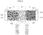
- Fig. 3 is a schematic sectional view illustrating an embodiment of a solid electrolyte of the present disclosure.
- Fig. 3 is a schematic sectional view illustrating an embodiment of a solid-state battery. As illustrated in Fig. 3 , a negative electrode layer A, a solid electrolyte layer B and a positive electrode layer C are layered.
- a negative electrode active material is denoted by reference numeral 101
- a positive electrode active material is denoted by reference numeral 103
- conduction assistants are denoted by reference numerals 105 and 107
- binders are denoted by reference numerals 109 and 111
- a negative electrode collector is denoted by reference numeral 113
- a positive electrode collector is denoted by reference numeral 115.
- the solid electrolyte layer may be a two-layer structure as illustrated in Fig. 3 .
- the solid-state battery may be structured such that the layer end surfaces (side surfaces) of a layered structure of a positive electrode / a solid electrolyte layer / a negative electrode are sealed by a resin.
- the collector of the electrode may be a structure in which a shock-absorbing layer, an elastic layer or a PTC (Positive Temperature Coefficient) thermistor layer is disposed on the surface of the collector.
- the solid-state battery may have only one power generating unit or may have two or more power generating units. In a case in which the solid-state battery has two or more power generating units, these power generating units may be connected in series or may be connected in parallel.
- the solid-state battery includes a negative electrode layer.
- the negative electrode layer is structured by the above-described negative electrode of the present disclosure.
- the solid-state battery includes a positive electrode layer.
- the positive electrode layer contains a positive electrode active material.
- the positive electrode layer is a layer having, for example, a positive electrode collector and a positive electrode active material layer that is provided on the positive electrode collector and contains a positive electrode active material.
- the positive electrode active material preferably contains a lithium composite oxide.
- the lithium composite oxide may contain at least one type selected from the group consisting of F, Cl, N, S, Br and I. Further, the lithium composite oxide may have a crystal structure belonging to at least one space group selected from space groups R-3m, Immm, and P63-mmc (also called P63mc, P6/mmc).
- the main sequence of a transition metal, oxygen and lithium may be an O2-type structure.
- lithium composite oxides having a crystal structure belonging to R-3m are compounds expressed by Li x Me y O ⁇ X ⁇ (Me represents at least one type selected from the group consisting of Mn, Co, Ni, Fe, Al, Cu, V, Nb, Mo, Ti, Cr, Zr, Zn, Na, K, Ca, Mg, Pt, Au, Ag, Ru, W, B, Si and P, and X represents at least one type selected from the group consisting of F, Cl, N, S, Br and I, and 0.5 ⁇ x ⁇ 1.5, 0.5 ⁇ y ⁇ 1.0, 1 ⁇ 2, 0 ⁇ 1 are satisfied).
- lithium composite oxides having a crystal structure belonging to Immm are composite oxides expressed by Li x1 M 1 A 1 2 (1.5 ⁇ x1 ⁇ 2.3 is satisfied, M 1 includes at least one type selected from the group consisting of Ni, Co, Mn, Cu and Fe, A 1 includes at least oxygen, and the ratio of the oxygen contained in A 1 is greater than or equal to 85 atom%) (a specific example is Li 2 NiO 2 ), and composite oxides expressed by Li x1 M 1A 1-x2 M 1B x2 O 2-y A 2 y (0 ⁇ x2 ⁇ 0.5 and 0 ⁇ y ⁇ 0.3, at least one of x2 and y is not 0, M 1A represents at least one type selected from the group consisting of Ni, Co, Mn, Cu and Fe, M 1B represents at least one type selected from the group consisting of Al, Mg, Sc, Ti, Cr, V, Zn, Ga, Zr, Mo, Nb, Ta and W, and A2 represents at least one type selected from the group consisting of F, Cl, Br, S and P
- lithium composite oxides having a crystal structure belonging to P63-mmc are composite oxides expressed by M1 x M2 y O 2 (M1 represents an alkali metal (at least one of Na and K is preferable), M2 represents a transition metal (at least one type selected from the group consisting of Mn, Ni, Co and Fe is preferable), and x+y satisfies 0 ⁇ x+y ⁇ 2).
- M1 represents an alkali metal (at least one of Na and K is preferable)
- M2 represents a transition metal (at least one type selected from the group consisting of Mn, Ni, Co and Fe is preferable)
- x+y satisfies 0 ⁇ x+y ⁇ 2).
- lithium composite oxides having an O2-type structure are composite oxides expressed by Li x [Li ⁇ (Mn a Co b M c ) 1- ⁇ ]O 2 (0.5 ⁇ x ⁇ 1.1, 0.1 ⁇ 0.33, 0.17 ⁇ a ⁇ 0.93, 0.03 ⁇ b ⁇ 0.50, 0.04 ⁇ c ⁇ 0.33, and M represents at least one type selected from the group consisting of Ni, Mg, Ti, Fe, Sn, Zr, Nb, Mo, W and Bi). Specific examples are Li 0.744 [Li 0.145 Mn 0.625 Co 0.115 Ni 0.115 ]O 2 and the like.
- the positive electrode layer may further contain at least one of a conductive material, a solid electrolyte and a binder as needed. Thereamong, it is preferable that the positive electrode layer contain a solid electrolyte.
- Examples of the conductive material are similar to those exemplified as conductive materials that can be contained in the negative electrode layer.
- solid electrolyte selected from the group of solid electrolytes consisting of sulfide solid electrolytes, oxide solid electrolytes, and halide solid electrolytes is contained as the solid electrolyte.
- a form in which at least a portion of the surface of the positive electrode active material is covered by a sulfide solid electrolyte, an oxide solid electrolyte or a halide solid electrolyte is preferable.
- Li 6-(4-x)b (Ti 1-x Al x ) b F 6 (0 ⁇ x ⁇ 1, 0 ⁇ b ⁇ 1.5) [LTAF electrolyte] is preferable as the halide solid electrolyte that covers at least a portion of the surface of the positive electrode active material.
- binder examples are similar to those exemplified as binders that can be contained in the negative electrode layer.
- the thickness of the positive electrode active material layer is preferably from 0.1 ⁇ m to 100 ⁇ m, and more preferably from 1 ⁇ m to 100 ⁇ m, and even more preferably from 30 ⁇ m to 100 ⁇ m.
- the positive electrode collector carries out power collection of the positive electrode layer.
- the positive electrode collector is disposed at a position at the side of the positive electrode layer, which side is opposite the side at which the solid electrolyte layer is located.
- Examples of the material of positive electrode collector are stainless steel, aluminum, nickel, iron, titanium, carbon and the like.
- Examples of the form of the positive electrode collector are the form of a foil and the form of a mesh.
- the solid-state battery includes a solid electrolyte layer.
- At least one type of solid electrolyte selected from the group of solid electrolytes consisting of sulfide solid electrolytes, oxide solid electrolytes, and halide solid electrolytes is contained as the solid electrolyte.
- the sulfide solid electrolyte preferably contains sulfur (S) as the main component that is an anion element, and further, preferably contains, for example, the element Li, element A and the element S.
- Element A is at least one type selected from the group consisting of P, As, Sb, Si, Ge, Sn, B, Al, Ga and In.
- the sulfide solid electrolyte may further contain at least one of O and a halogen element. Examples of the halogen element (X) are F, Cl, Br, I and the like.
- the composition of the sulfide solid electrolyte is not particularly limited, and examples are xLi 2 S•(100-x)P 2 S 5 (70 ⁇ x ⁇ 80) and yLiI•zLiBr• (100-y-z)(xLi 2 S•(1-x)P 2 S 5 ) (0.7 ⁇ x ⁇ 0.8, 0 ⁇ y ⁇ 30, 0 ⁇ z ⁇ 30).
- the sulfide solid electrolyte may have the composition expressed by following general formula (1). Li 4-x Ge 1-x P x S 4 (0 ⁇ x ⁇ 1) ... formula (1)
- At least a portion of Ge may be substituted by at least one selected from the group consisting of Sb, Si, Sn, B, Al, Ga, In, Ti, Zr, V and Nb.
- at least a portion of P may be substituted by at least one selected from the group consisting of Sb, Si, Sn, B, Al, Ga, In, Ti, Zr, V and Nb.
- a portion of Li may be substituted by at least one selected from the group consisting of Na, K, Mg, Ca and Zn.
- a portion of S may be substituted by a halogen.
- the halogen is at least one of F, Cl, Br and I.
- the oxide solid electrolyte preferably contains oxygen (O) as the main component that is an anion element, and, for example, may contain Li, element Q (Q represents at least one of Nb, B, Al, Si, P, Ti, Zr, Mo, W and S), and O.
- O oxygen
- Examples of the oxide solid electrolyte are garnet type solid electrolytes, perovskite type solid electrolytes, NASICON type solid electrolytes, Li-P-O solid electrolytes, Li-B-O solid electrolytes, and the like.
- garnet type solid electrolytes are Li 7 La 3 Zr 2 O 12 , Li 7-x La 3 (Zr 2-x Nb x )O 12 (0 ⁇ x ⁇ 2), Li 5 La 3 Nb 2 O 12 , and the like.
- Examples of perovskite type solid electrolytes are (Li,La)TiO 3 , (Li,La)NbO 3 , (Li,Sr)(Ta,Zr)O 3 and the like.
- Examples of NASICON type solid electrolytes are Li(Al,Ti)(PO 4 ) 3 , Li(Al,Ga)(PO 4 ) 3 , and the like.
- Examples of Li-P-O solid electrolytes are Li 3 PO 4 and LIPON (compounds in which some of the O in Li 3 PO 4 is substituted with N).
- Examples of Li-B-O solid electrolytes are Li 3 BO 3 , compounds in which some of the O in Li 3 BO 3 is substituted with C, and the like.
- solid electrolytes containing Li, M and X (M represents at least one of Ti, Al and Y, and X represents F, Cl or Br) are suitable.
- Li 6-3z Y z X 6 (X represents Cl or Br, and z satisfies 0 ⁇ z ⁇ 2) and Li 6-(4-x)b (Ti 1-x Al x ) b F 6 (0 ⁇ x ⁇ 1, 0 ⁇ b ⁇ 1.5) are preferable.
- Li 6-3z Y z X 6 from the standpoint of having excellent lithium ion conductivity, Li 3 YX 6 (X represents Cl or Br) is more preferable, and Li3 YCl6 is even more preferable.
- Li 6-(4-x)b (Ti 1-x Al x ) b F 6 (0 ⁇ x ⁇ 1, 0 ⁇ b ⁇ 1.5) be contained together with a solid electrolyte such as a sulfide solid electrolyte or the like.
- the ratio of the negative electrode active material layer and the solid electrolyte layer is not particularly limited, but, for example, is preferably from 85/15 to 30/70, and is more preferably 80/20 to 40/60.
- the ratio of the positive electrode active material layer and the solid electrolyte layer is not particularly limited, but, for example, is preferably from 85/15 to 30/70, and is more preferably from 80/20 to 50/50.
- the solid-state battery may further have an exterior body.
- the exterior body houses at least the above-described power generating unit. Examples of the exterior body are a laminate-type exterior body, a case-type exterior body, and the like.
- the solid-state battery may further have a restraining member.
- the restraining member applies restraining pressure in the thickness direction to the positive electrode layer, the solid electrolyte layer and the negative electrode layer.
- the restraining pressure is preferably 0.1 MPa or more, and is more preferably 1 MPa or more, and is even more preferably 5 MPa or more.
- the restraining pressure is preferably 100 MPa or less, and more preferably 50 MPa or less, and even more preferably 20 MPa or less.
- the restraining pressure is preferably from 0.1 MPa to 100 MPa.
- the solid-state battery of the present disclosure is a typical solid-state secondary battery (more preferably, a solid-state lithium ion secondary battery).
- the solid-state battery can be used, for example, as the power source of a vehicle, electronic equipment, electrical storage devices, and the like.
- Examples of vehicles are electric four-wheel vehicles, electric two-wheel vehicles, gasoline-powered vehicles, diesel-powered vehicles and the like.
- Examples of electric four-wheel vehicles are electric vehicles (BEVs), plug-in hybrid vehicles (PHEVs), hybrid vehicles (BEVs), and the like.
- Examples of electric two-wheel vehicles are electric motorbikes, electrically assisted bicycles and the like.
- the solid-state battery of the present disclosure is preferably used as a power source for the driving of hybrid vehicles, plug-in hybrid vehicles, and electric vehicles.
- porous Si that is a porous material
- PDADMAC poly(diallyldimethylammonium chloride)
- Mw weight average molecular weight
- quaternary ammonium salt group as the cation
- the primary particles that were prepared as described above were dispersed in a solution in which poly(vinylidene fluoride-co-hexafluoropropylene) (PVdF-HFP, a fluorine-based polymer containing a structural unit derived from vinylidene fluoride, KF8300 manufactured by Kureha Corporation) was dissolved in dimethyl carbonate such that the mass ratio of the PDADMAC and PVdF-HFP was 5:95.
- PVdF-HFP poly(vinylidene fluoride-co-hexafluoropropylene)
- the total amount of the polymer components i.e., the total amount of the cationic polymer and the fluorine-based polymer
- the content of the cationic polymer (PDADMAC) with respect to the total amount of the polymer components of the granulated particles was 5 mass%.
- a negative electrode active material was obtained by using the same specifications as Example 1, except that the mass ratio of PDADMAC and PVdF-HFP was made to be 10:90 (i.e., the content of the cationic polymer (PDADMAC) with respect to the total amount of the polymer components of the granulated particles was made to be 10 mass%).
- the mass ratio of PDADMAC and PVdF-HFP was made to be 10:90 (i.e., the content of the cationic polymer (PDADMAC) with respect to the total amount of the polymer components of the granulated particles was made to be 10 mass%).
- a negative electrode active material was obtained by using the same specifications as Example 1, except that the added amounts of the cationic polymer and the fluorine-based polymer were adjusted such that the total amount of the polymer components (i.e., the total amount of the cationic polymer and the fluorine-based polymer) with respect to the granulated particles on the whole was 20 mass%.
- a negative electrode active material was obtained by using the same specifications as Example 1, except that the mass ratio of PDADMAC and PVdF-HFP was made to be 10:90 (i.e., the content of the cationic polymer (PDADMAC) with respect to the total amount of the polymer components of the granulated particles was made to be 10 mass%), and the added amounts of the cationic polymer and the fluorine-based polymer were adjusted such that the total amount of the polymer components (i.e., the total amount of the cationic polymer and the fluorine-based polymer) with respect to the granulated particles on the whole was 20 mass%.
- the mass ratio of PDADMAC and PVdF-HFP was made to be 10:90 (i.e., the content of the cationic polymer (PDADMAC) with respect to the total amount of the polymer components of the granulated particles was made to be 10 mass%), and the added amounts of the cationic polymer and the fluorine-based polymer were adjusted such that
- porous Si that is a porous material was added into a dimethyl carbonate solution in which 0.5 parts of PVdF-HFP that is a fluorine-based polymer was dissolved, and thereafter, stirring was carried out and the porous Si was dispersed.
- a spray drier the solution was granulated, and a negative electrode active material, which was granulated particles that contained primary particles containing a silicon material, and a fluorine-based polymer, was obtained.
- the total amount of the polymer components i.e., the total amount of the cationic polymer and the fluorine-based polymer
- the content of the cationic polymer (PDADMAC) with respect to the total amount of the polymer components of the granulated particles was 0 mass%.
- a mixed solvent of dibutylether and mesitylene, a butyl acetate solution of 5 wt% PVDF binder, VGCF that is a conduction assistant, and Li 2 S-P 2 S 5 glass ceramic that is a solid electrolyte were placed in a container made of PP and stirred. Thereafter, the negative electrode active material of each example was further added thereto, and this mixture was stirred for 30 seconds by an ultrasonic disperser (UH-50 manufactured by SMT Co., Ltd.). Next, the mixture was shaken for 30 minutes by a shaker (TTM-1 manufactured by Sibata Scientific Technology Ltd.). The mixture was then coated on a Cu foil (manufactured by UACJ) by a blade method using an applicator. The coated electrode was dried for 30 minutes on a hot plate of 100°C, and a negative electrode layer was obtained.
- UH-50 manufactured by SMT Co., Ltd. an ultrasonic disperser
- TTM-1 manufactured by Sibata Scientific Technology Ltd.
- a butyl acetate solvent, a butyl acetate solution of 5 wt% PVDF binder, LiNi 1/3 Co 1/3 Mn 1/3 O 2 of an average particle diameter of 6 ⁇ m that is a positive electrode active material, an Li 2 S-P 2 S 5 glass ceramic that is a sulfide solid electrolyte, and VGCF that is a conduction assistant were placed in a container made of PP and mixed together, and were stirred for 30 seconds by an ultrasonic disperser (UH-50 manufactured by SMT Co., Ltd.). Next, the mixture was shaken for 3 minutes by a shaker (TTM-1 manufactured by Sibata Scientific Technology Ltd.), and was further stirred for 30 seconds by the ultrasonic disperser. Thereafter, this solution was coated on an Al foil (manufactured by Showa Denko) by a blade method using an applicator. The coated electrode was dried for 30 minutes on a hot plate of 100°C, and a positive electrode layer was obtained.
- a heptane solvent, a heptane solution of 5 wt% SBR binder, and an Li 2 S-P 2 S 5 glass ceramic that is a solid electrolyte were added into a container made of PP, and were stirred for 30 seconds by an ultrasonic disperser (UH-50 manufactured by SMT Co., Ltd.). Next, the mixture was shaken for 30 minutes by a shaker (TTM-1 manufactured by Sibata Scientific Technology Ltd.). Thereafter, this solution was coated on an Al foil by a blade method using an applicator. The coated electrode was dried for 30 minutes on a hot plate of 100°C, and a solid electrolyte layer was obtained.
- the above-described positive electrode layer and a first solid electrolyte layer were layered in that order.
- This layered body was set in a roll press, and was pressed with the press pressure in this first pressing step being 100 kN/cm and the pressing temperature being 165°C, and a positive electrode layered body was thereby obtained.
- the above-described negative electrode layer was set in a roll press, and was pressed with the press pressure in this second pressing step being 60 kN/cm and the pressing temperature being 25°C, and a negative electrode layered body was thereby obtained.
- This layered body was set in a flat, uniaxial press machine, and was temporarily pressed for 10 seconds at 100 MPa and 25°C.
- the Al foil was peeled-off from the intermediate solid electrolyte layer of this layered body, and a negative electrode layered body in which an intermediate solid electrolyte layer was further layered (intermediate solid electrolyte layer / second solid electrolyte layer / negative electrode active material layer / negative electrode collector layer) was obtained.
- the negative electrode layered body and the positive electrode layered body were fabricated such that the surface area of the negative electrode layered body was larger than the surface area of the positive electrode layered body.
- This layered body (positive electrode layered body / first solid electrolyte layer / intermediate solid electrolyte layer / second solid electrolyte layer / negative electrode active material layer / negative electrode collector layer) was set in a flat, uniaxial press machine, and was pressed for one minute with the press pressure in this third pressing step being 200 MPa and the pressing temperature being 120°C. A solid-state battery was thereby obtained.
- the solid-state batteries fabricated by using the negative electrode active materials of the respective examples were restrained at a predetermined restraining pressure by using a restraining jig, and were charged at a constant current at 1/10 C until 4.55 V, and thereafter, were discharged at 1 C to 3.0 V, and constant current - constant voltage charging was carried out at 1/3 C to 4.35 V, and constant current - constant voltage discharging was carried out at 1/3 C until 3.00 V. Thereafter, a constant current charging/discharging test was repeated 200 times at 2 C as a cycling test. The maintenance rate from the initial discharge capacity of the cycling test that was obtained was calculated as the discharge capacity maintenance rate after 200 cycles.
- the discharge capacity maintenance rates after 200 cycles in the Examples were relative values with respect to the discharge capacity maintenance rate after 200 cycles of Comparative Example 1.
- Fig. 1 is a graph illustrating the relationship between the relative value of the discharge capacity maintenance rate after 200 cycles and the content of the cationic polymer with respect to the total amount of the polymer components of the negative electrode active material in Examples 1, 2 and Comparative Example 1.
- Fig. 2 is a graph illustrating the relationship between the relative value of the discharge capacity maintenance rate after 200 cycles and the content of the cationic polymer with respect to the total amount of the polymer components of the negative electrode active material in Examples 3, 4 and Comparative Example 1.
- the solid-state batteries that contain the negative electrode active material of the Examples have an excellent discharge capacity maintenance rate after 200 cycles, as compared with the solid-state battery containing the negative electrode active material of the Comparative Example.
- Example 2 in which the content of the cationic polymer with respect to the total amount of the polymer components of the negative electrode active material is 10 mass%, as compared with Example 1 in which the content is 5 mass%.
- Example 3 the discharge capacity maintenance rate after 200 cycles is better in Example 3 in which the content of the cationic polymer with respect to the total amount of the polymer components of the negative electrode active material is 5 mass%, as compared with Example 4 in which the content is 10 mass%.
Landscapes
- Chemical & Material Sciences (AREA)
- Chemical Kinetics & Catalysis (AREA)
- Electrochemistry (AREA)
- General Chemical & Material Sciences (AREA)
- Engineering & Computer Science (AREA)
- Manufacturing & Machinery (AREA)
- Composite Materials (AREA)
- Materials Engineering (AREA)
- Inorganic Chemistry (AREA)
- Physics & Mathematics (AREA)
- Condensed Matter Physics & Semiconductors (AREA)
- General Physics & Mathematics (AREA)
- Battery Electrode And Active Subsutance (AREA)
- Secondary Cells (AREA)
Abstract
Description
- The present disclosure relates to a negative electrode active material, a negative electrode, and a solid-state battery.
- In recent years, secondary batteries such as lithium ion secondary batteries and the like have been suitably used as portable power sources for personal computers, portable terminals and the like, and as power sources for the driving of vehicles such as electric vehicles (EVs), hybrid vehicles (HVs), plug-in hybrid vehicles (PHVs) and the like, and the like.
- Because electrolytic liquids containing flammable organic solvents are used in secondary batteries, there is the need for improvement in structures and materials for preventing short-circuiting and for mounting safety devices that suppress a rise in temperature at the time of short-circuiting. To address this, solid-state batteries, which use a solid electrolyte layer instead of an electrolytic liquid and in which the materials are made solid, do not use flammable organic solvents at the battery interior, and therefore, it is thought that simplification of safety devices is devised, and the manufacturing cost and mass producibility are excellent.
- A technique of improving energy density by including Si in a negative electrode active material is known as a technique relating to the negative electrode of a solid-state battery. With such a negative electrode active material that contains Si, the energy density can be improved by the inclusion of Si. However, on the other hand, due to volumetric expansion/contraction that accompanies charging/discharging, gaps arise between the negative electrode active material layer and the solid electrolyte layer, and due thereto, there is the tendency for a phenomenon, in which the cell resistance after charging/discharging increases, to occur. Therefore, recently, a technique has been known that attempts to suppress the formation of gaps between the negative electrode active material layer and the solid electrolyte layer due to volumetric expansion/contraction that accompanies charging/discharging, by using, as the negative electrode active material, granulated particles of primary particles, which contain a silicon material, and a binder resin such as a fluorine-based polymer or the like (for example, Japanese Patent Application Laid-Open (
JP-A) No. 2019-021571 - However, in a conventional negative electrode active material that is granulated particles of primary particles, which contain a silicon material, and a fluorine-based polymer, the silicon and the fluorine-based polymer surface charges are respectively charged negatively, and therefore, it is easy for the primary particles and the fluorine-based polymer to electrostatically repel one another. Therefore, the adhesion between the primary particles and the fluorine-based polymer is low, and due thereto, there is the tendency for the granulated particles to be weak, and the cycle characteristic (e.g., the discharge capacity maintenance rate after 200 cycles) to deteriorate.
Thus, in view of the above-described circumstances, a topic of the present disclosure is the provision of a negative electrode active material, a negative electrode and a solid-state battery that suppress a deterioration in the cycle characteristic when a battery has the negative electrode that contains the negative electrode active material in a negative electrode active material layer. - Means for addressing the above-described topic include the following means.
- <1> A negative electrode active material, comprising: granulated particles, the granulated particles comprising: primary particles containing at least a silicon material and a cationic polymer; and a fluorine-based polymer.
- <2> The negative electrode active material of <1>, wherein the cationic polymer includes a polymer having a quaternary ammonium salt group as a cation.
- <3> The negative electrode active material of <1> or <2>, wherein the fluorine-based polymer is a polymer containing a structural unit derived from vinylidene fluoride.
- <4> The negative electrode active material of any one of <1> through <3>, wherein a total amount of polymer components with respect to the negative electrode active material is from 5 mass% to 25 mass%, and a content of the cationic polymer with respect to a total amount of polymer components of the negative electrode active material is from 3 mass% to 10 mass%.
- <5> The negative electrode active material of any one of <1> through <4>, wherein the silicon material includes at least one of porous silicon or a silicon clathrate compound.
- <6> A negative electrode, comprising the negative electrode active material of any one of <1> through <5>.
- <7> A solid-state battery, comprising: the negative electrode of <6>; a positive electrode; and a solid electrolyte layer.
- According to the present disclosure, a negative electrode active material, a negative electrode and a solid-state battery that suppress deterioration in cycle characteristics when used in a solid-state battery, are provided.
- Exemplary embodiments of the present disclosure will be described in detail based on the following figures, wherein:
-
Fig. 1 is a graph illustrating the relationship between the relative value of the discharge capacity maintenance rate after 200 cycles and the content of a cationic polymer with respect to the total amount of the polymer components of a negative electrode active material in Examples 1, 2 and Comparative Example 1; -
Fig. 2 is a graph illustrating the relationship between the relative value of the discharge capacity maintenance rate after 200 cycles and the content of a cationic polymer with respect to the total amount of the polymer components of a negative electrode active material in Examples 3, 4 and Comparative Example 1; and -
Fig. 3 is a cross-sectional view illustrating an embodiment of a solid-state battery of the present disclosure. - Embodiments that are examples of the present disclosure are described hereinafter. The description thereof and the Examples are for exemplifying embodiments, and are not intended to limit the scope of the present disclosure.
- In the present disclosure, numerical ranges expressed by using "~" mean ranges in which the numerical values listed before and after the "~" are included as the minimum value and the maximum value.
- In numerical value ranges that are expressed in a stepwise manner in the present disclosure, the upper limit value or the lower limit value listed in a numerical value range may be substituted by the upper limit value or the lower limit value of another numerical value range that is expressed in a stepwise manner. Further, in the numerical value ranges put forth in the present disclosure, the upper limit value or the lower limit value of a numerical value range may be substituted by a value shown in the Examples.
- In the present disclosure, in a case in which there are plural materials corresponding to respective components in a composition, the amount of the respective components in the composition means the total amount of the plural materials existing in the composition, unless otherwise indicated.
- In the present disclosure "mass" and "weight" have the same meanings, and "mass%" and "weight%" have the same meanings.
- In the present disclosure, combinations of two or more preferable aspects are more preferable aspects.
- When describing groups (atom groups) in the present disclosure, if it is not stated whether a group is substituted or unsubstituted, the group may be either substituted or unsubstituted.
- In the present disclosure, the term "layer" includes cases in which, when observing a region in which a layer exists, the layer is formed at the entirety of that region, and in addition thereto, also includes cases in which the layer is formed only at a portion of that region. In the present disclosure, the term "step" is not only an independent step and includes steps that, in a case in which that step cannot be clearly distinguished from another step, achieve the intended object of that step.
- The negative electrode active material relating to the present disclosure is granulated particles that contain primary particles, which contain at least a silicon material and a cationic polymer, and a fluorine-based polymer.
- In accordance with the present disclosure, because the primary particles contain a cationic polymer in addition to the silicon material, the surface charge of the primary particles being a negative charge is suppressed. As a result, electrostatic repulsion of the primary particles and the fluorine-based polymer is suppressed, and the adhesion of the both can be improved. Therefore, at a battery that has a negative electrode including a negative electrode active material layer that contains the negative electrode active material, a deterioration in the cycle characteristic (e.g., the discharge capacity maintenance rate after 200 cycles) is suppressed.
- The primary particles contain at least a silicon material and a cationic polymer.
- The primary particles may further contain other materials that are other than a silicon material and a cationic polymer. Examples of these other materials are binder materials such as polyvinylidene fluoride (PVdF), styrene-butadiene rubber (SBR) and the like, and the like.
- For example, from the standpoint of improving the adhesion between the primary particles and the fluorine-based polymer and obtaining a better cycle characteristic, the primary particles are preferably primary particles in which the cationic polymer covers at least partial regions of the particle surfaces of the silicon material, and are more preferably primary particles in which the cationic polymer covers the entire particle surfaces of the silicon material.
- The aforementioned form of covering the primary particles can be confirmed by the strength ratio of C and Si measured by energy diffraction spectrometry (EDS) (measuring conditions: acceleration voltage: 5kV, emission current).
- Specifying of the silicon material in the primary particles can be confirmed by X-ray diffraction (XRD) measurement (scanning speed: 1 deg/min).
- Specifying of the cationic polymer in the primary particles can be confirmed by gas chromatography - mass spectrometry (GC-MS). Further, in confirming that the polymer is a cationic polymer, the charge of the polymer can be confirmed by dissolving a sample of the polymer in water and measuring the zeta potential by a zeta potentiometer.
- The silicon material contains silicon. The silicon is not particularly limited provided that it is a material that can be employed as a negative electrode active material, and examples thereof are elemental silicon particles, silicon alloy particles (e.g., alloys or the like of Si and one or more metals selected from the group consisting of Sn, Ti, Fe, Ni, Cu, Co and Al), porous silicon, silicon clathrate compounds, silicon oxides, compounds of these, and the like.
- Thereamong, from the standpoint of better suppressing volumetric expansion/contraction that accompanies charging/discharging, the silicon material preferably contains at least one of porous silicon or a silicon clathrate compound, and more preferably contains porous silicon.
- One type of silicon material may be used alone, or two or more types may be used in combination.
- The silicon material may be, for example, a mixture of porous silicon or a silicon clathrate compound, i.e., may be in a state in which a silicon monocrystal and a silicon cluster both exist within a single particle.
- Porous silicon means a monocrystalline silicon that has been made porous.
- Silicon clathrate compounds mean compounds in which a silicon cluster is the structural unit of the crystal, and, more specifically, mean compounds having a silicon clathrate type crystal phase.
- Silicon clathrate compounds are classified into type I and type II in accordance with the type of the crystal phase thereof.
In the silicon clathrate compound, the silicon material preferably contains at least one crystal phase among type I and type II, and more preferably has one crystal phase among type I and type II as the main phase, and even more preferably has type II as the main phase. Here, "has a silicon clathrate type I or type II crystal phase as the main phase" means that any peak belonging to a silicon clathrate type I or type II crystal phase is the peak of the largest diffracted intensity among the peaks observed by X-ray diffraction measurement. - Silicon clathrate compounds are preferable from the standpoint that, because metal ions such as Li ions and the like can enter into the three-dimensional, cage-shaped structure, the amount of expansion is small, and, because fluctuations in volume accompanying charging/discharging of the battery are small, the cycle characteristic is even better.
- A cationic polymer means a polymer having a cationic group or a group that becomes a cationic group when ionized. Amphoteric polymers that are cationic as a polymer on the whole also are included in this concept.
- Examples of cationic polymers are polyethyleneimine; polyvinylamine; polyallylamine; polyaniline; polypyrrole; polyvinyl pyridine; polymers and copolymers of allylamine, pyridinium salt, allylamine hydrochloride, allylamine acetate, allylamine sulfate, diallylamine, diallylamine hydrochloride, diallylamine acetate, diallylamine sulfate, diallylmethylamine and salts thereof (examples of the salts are hydrochloride, acetate, sulfate and the like), and the like; polymers and copolymers of diallylethylamine and salts thereof (examples of the salts are hydrochloride, acetate, sulfate and the like), and the like; polymers and copolymers of diallyldimethyl ammonium salts (chloride, acetate ions, sulfate ions and the like are examples of counter anions of these salts) (e.g., polydiallyldimethyl ammonium chloride: PDADMAC). One type of cationic polymer may be used alone or two or more types may be used in combination.
- Thereamong, from the standpoint of more efficiently making the primary particles cationic and improving the adhesion between the primary particles and the fluorine-based polymer, the cationic polymer preferably contains a polymer and copolymer of diallyldimethyl ammonium salt or the like, and more preferably contains PDADMAC.
- Examples of the cationic polymer are polymers having a primary amino group, a secondary amino group, a tertiary amino group or a quaternary ammonium salt group as the cation. One type of cationic polymer may be used alone or two or more types may be used in combination.
- Thereamong, from the standpoint of more efficiently making the primary particles cationic and improving the adhesion between the primary particles and the fluorine-based polymer, the cationic polymer preferably contains a polymer having a quaternary ammonium salt group as the cation, and more preferably contains a polymer having a quaternary ammonium salt group.
- Note that counter anions of the quaternary ammonium salt are not particularly limited, and known anions can be used. However, from the standpoint of not impeding the battery characteristics even better, the counter anions may be chlorine ions.
- The polystyrene conversion weight average molecular weight (Mw) of the cationic polymer determined by gel permeation chromatography (GPC) is not particularly limited, and, for example, from the standpoint of more efficiently making the primary particles cationic and improving the adhesion between the primary particles and the fluorine-based polymer, is preferably from 50,000 to 600,000, and more preferably from 80,000 to 5,500,000, and even more preferably from 100,000 to 5,000,000.
- From the standpoint of more efficiently making the primary particles cationic and improving the adhesion between the primary particles and the fluorine-based polymer, the content of the cationic polymer, with respect to the total amount of the polymer components of the negative electrode active material, is preferably from 1 mass% to 15 mass%, and more preferably from 3 mass% to 15 mass%, and even more preferably from 3 mass% to 10 mass%.
- The primary particles may further contain other materials other than a silicon material and a cationic polymer, within ranges in which the effects of the present disclosure can be exhibited. Examples of these other materials are binder materials such as polyvinylidene fluoride (PVdF), styrene-butadiene rubber (SBR) and the like, and the like.
- The fluorine-based polymer means a polymer containing a structural unit derived from a fluorine-group-containing compound.
- The fluorine-based polymer is not particularly limited, and known materials can be used therefor. Examples of the fluorine-based polymer are vinylidene fluoride resin (PVdF), poly(vinylidene fluoride-co-hexafluoropropylene) (PVdF-HFP), polytetrafluoroethylene (PTFE), perfluoroethylene propylene copolymer (FEP), poly chlorotrifluoroethylene resin (PCTFE), poly vinyl fluoride resin (PVF), poly tetrafluoroethylene perfluoroalkyl vinyl ether resin (PFA), ethylene - tetrafluoroethylen resin (ETFE), ethylenechlorotrifluoroethylene resin (ECTFE) and the like. One type of fluorine-based polymer may be used alone, or two or more types may be used in combination.
- Thereamong, from the standpoint of more efficiently improving the adhesion between the primary particles and the fluorine-based polymer, and from the standpoint of the battery characteristics, it is preferable that the fluorine-based polymer be a polymer containing a structural unit derived from vinylidene fluoride. Specifically, it is preferable that at least one of PVdF and PVdF-HFP be contained as the fluorine-based polymer, and it is more preferable that PVdF-HFP be contained.
- The polystyrene conversion weight average molecular weight (Mw) of the fluorine-based polymer determined by gel permeation chromatography (GPC) is not particularly limited, and, for example, from the standpoint of more efficiently making the primary particles cationic and improving the adhesion between the primary particles and the fluorine-based polymer, is preferably from 50,000 to1,000,000, and more preferably from 200,000 to 900,000, and even more preferably from 300,000 to 800,000.
- In the negative electrode active material, from the standpoint of more efficiently making the primary particles cationic and improving the adhesion between the primary particles and the fluorine-based polymer, and from the standpoint of the battery characteristics, the total amount of the polymer components with respect to the negative electrode active material is from 5 mass% to 25 mass%, and the content of the cationic polymer with respect to the total amount of the polymer components of the granulated particles is preferably from 3 mass% to 10 mass%.
- From the standpoint of more efficiently making the primary particles cationic and improving the adhesion between the primary particles and the fluorine-based polymer, and from the standpoint of the battery characteristics, the total amount of the polymer components in the negative electrode active material (i.e., the total amount of the polymer components including the cationic polymer and the fluorine-based polymer) with respect to the negative electrode active material is preferably from 1 mass% to 30 mass%, and more preferably from 5 mass% to 25 mass%, and even more preferably from 10 mass% to 20 mass%.
- The negative electrode active material may be granulated particles that further include other materials in addition to the primary particles and the fluorine-based polymer, and that have been granulated. Examples of these other materials are binder materials such as polyvinylidene fluoride (PVdF), styrene-butadiene rubber (SBR) and the like, and the like.
- An example of the shape of the negative electrode active material is particle-shaped.
- The particle diameter of the negative electrode active material is not particularly limited, and, for example, from the standpoint of the battery characteristics, is preferably from 10 µm to 100 µm, and is more preferably from 10 µm to 50 µm.
- From the standpoint of having a better cycle characteristic, the particle diameter of the negative electrode active material is preferably from 0.5 µm to 100 µm, and is more preferably from 1 µm to 50 µm.
- With regard to the particle diameter of the negative electrode active material, the negative electrode active material is dispersed in a dispersion medium, and the volume-based particle size distribution is measured by using a laser diffraction particle size analyzer. The particle diameter, at which the value of the obtained volume-based cumulative particle size distribution corresponds to 50%, is used as the particle diameter of the negative electrode active material.
- The method of manufacturing the negative electrode active material of the present disclosure is not particularly limited, and a known method of manufacturing a negative electrode active material can be used. The negative electrode active material of the present disclosure may manufactured by, for example, mixing a silicon material and a cationic polymer together in a solution, and thereafter, heating and kneading and forming primary particles, and thereafter, dispersing and granulating the primary particles in a solution system containing a fluorine-based polymer.
- The negative electrode of the present disclosure contains the negative electrode active material of the present disclosure.
- In accordance with the present disclosure, when the negative electrode is used in a solid-state battery, deterioration of the cycle characteristic is suppressed.
- The negative electrode of the present disclosure is, for example, a layer that has a negative electrode collector and a negative electrode active material layer that is provided on the negative electrode collector and contains the negative electrode active material. As needed, the negative electrode active material layer may further contain at least one of a conductive material, a solid electrolyte and a binder.
- Examples of the conductive material are carbon materials, conductive polymers, metal particles, and the like.
- Examples of carbon materials are particle-shaped carbon materials, fiber-shaped carbon materials and the like. Examples of particle-shaped carbon materials are acetylene black (AB), ketjen black (KB) and the like. Examples of fiber-shaped carbon materials are carbon nanotubes (CNT), carbon nanofibers (CNF), VGCF, and the like.
- Examples of conductive polymers are polythiophene, polyacetylene, poly(p-phenylene), polyisothianaphthene, and the like.
- Examples of metal particles are particles made of nickel, copper, iron, stainless steel and the like.
- Examples of the solid electrolyte are similar to those exemplified as the solid electrolytes that can be contained in the solid electrolyte layer.
- Examples of the binder are rubber binders, fluoride binders, and the like. Examples of rubber binders are butadiene rubber, hydrogenated butadiene rubber, styrene-butadiene rubber (SBR), hydrogenated styrene-butadiene rubber, nitrile butadiene rubber, hydrogenated nitrile butadiene rubber, ethylene propylene rubber and the like. Examples of fluoride binders are polyvinylidene fluoride (PVDF), polyvinylidene fluoride - polyhexafluoropropylene copolymer (PVDF-HFP), polytetrafluoroethylene, fluororubbers, and the like.
- The negative electrode collector performs power collection at the negative electrode layer. The negative electrode collector is disposed at a position which is at the side of the negative electrode layer opposite the side at which the solid electrolyte layer is disposed. Examples of the material of the negative electrode collector are stainless steel, copper, nickel, carbon and the like. Examples of the form of the negative electrode collector are the form of a foil and the form of a mesh.
- The thickness of the negative electrode active material layer is not particularly limited, and is preferably from 0.1 µm to 100 µm, and is more preferably from 1 µm to 100 µm, and is even more preferably from 30 µm to 100 µm.
- The solid-state battery of the present disclosure has the negative electrode of the present disclosure (hereinafter called negative electrode layer), a positive electrode (hereinafter called positive electrode layer), and a solid electrolyte layer.
- Solid-state batteries include solid state batteries that use an inorganic solid electrolyte (i.e., whose content of electrolytic liquid that serves as the electrolyte is less than 10 mass% of the entire amount of the electrolyte).
- In accordance with the present disclosure, a deterioration in the cycle characteristic is suppressed.
-
Fig. 3 is a schematic sectional view illustrating an embodiment of a solid electrolyte of the present disclosure. -
Fig. 3 is a schematic sectional view illustrating an embodiment of a solid-state battery. As illustrated inFig. 3 , a negative electrode layer A, a solid electrolyte layer B and a positive electrode layer C are layered. - In
Fig. 3 , a negative electrode active material is denoted byreference numeral 101, a positive electrode active material is denoted byreference numeral 103, conduction assistants are denoted byreference numerals reference numerals 109 and 111, a negative electrode collector is denoted byreference numeral 113, and a positive electrode collector is denoted byreference numeral 115. The solid electrolyte layer may be a two-layer structure as illustrated inFig. 3 . - The solid-state battery may be structured such that the layer end surfaces (side surfaces) of a layered structure of a positive electrode / a solid electrolyte layer / a negative electrode are sealed by a resin. The collector of the electrode may be a structure in which a shock-absorbing layer, an elastic layer or a PTC (Positive Temperature Coefficient) thermistor layer is disposed on the surface of the collector.
- Given that the power generating unit is the set of the positive electrode layer, the solid electrolyte layer and the negative electrode layer, the solid-state battery may have only one power generating unit or may have two or more power generating units. In a case in which the solid-state battery has two or more power generating units, these power generating units may be connected in series or may be connected in parallel.
- The solid-state battery includes a negative electrode layer. The negative electrode layer is structured by the above-described negative electrode of the present disclosure.
- The solid-state battery includes a positive electrode layer. The positive electrode layer contains a positive electrode active material.
- The positive electrode layer is a layer having, for example, a positive electrode collector and a positive electrode active material layer that is provided on the positive electrode collector and contains a positive electrode active material.
- The positive electrode active material preferably contains a lithium composite oxide. The lithium composite oxide may contain at least one type selected from the group consisting of F, Cl, N, S, Br and I. Further, the lithium composite oxide may have a crystal structure belonging to at least one space group selected from space groups R-3m, Immm, and P63-mmc (also called P63mc, P6/mmc). In the lithium composite oxide, the main sequence of a transition metal, oxygen and lithium may be an O2-type structure.
- Examples of lithium composite oxides having a crystal structure belonging to R-3m are compounds expressed by LixMeyOαXβ (Me represents at least one type selected from the group consisting of Mn, Co, Ni, Fe, Al, Cu, V, Nb, Mo, Ti, Cr, Zr, Zn, Na, K, Ca, Mg, Pt, Au, Ag, Ru, W, B, Si and P, and X represents at least one type selected from the group consisting of F, Cl, N, S, Br and I, and 0.5<x<1.5, 0.5≤y≤1.0, 1≤α<2, 0<β≤1 are satisfied).
- Examples of lithium composite oxides having a crystal structure belonging to Immm are composite oxides expressed by Lix1M1A1 2 (1.5≤x1≤2.3 is satisfied, M1 includes at least one type selected from the group consisting of Ni, Co, Mn, Cu and Fe, A1 includes at least oxygen, and the ratio of the oxygen contained in A1 is greater than or equal to 85 atom%) (a specific example is Li2NiO2), and composite oxides expressed by Lix1M1A 1-x2M1B x2O2-yA2 y (0≤x2≤0.5 and 0≤y≤0.3, at least one of x2 and y is not 0, M1A represents at least one type selected from the group consisting of Ni, Co, Mn, Cu and Fe, M1B represents at least one type selected from the group consisting of Al, Mg, Sc, Ti, Cr, V, Zn, Ga, Zr, Mo, Nb, Ta and W, and A2 represents at least one type selected from the group consisting of F, Cl, Br, S and P).
- Examples of lithium composite oxides having a crystal structure belonging to P63-mmc are composite oxides expressed by M1xM2yO2 (M1 represents an alkali metal (at least one of Na and K is preferable), M2 represents a transition metal (at least one type selected from the group consisting of Mn, Ni, Co and Fe is preferable), and x+y satisfies 0<x+y≤2).
- Examples of lithium composite oxides having an O2-type structure are composite oxides expressed by Lix[Liα(MnaCobMc)1-α]O2 (0.5<x<1.1, 0.1<α<0.33, 0.17<a<0.93, 0.03<b<0.50, 0.04<c<0.33, and M represents at least one type selected from the group consisting of Ni, Mg, Ti, Fe, Sn, Zr, Nb, Mo, W and Bi). Specific examples are Li0.744[Li0.145Mn0.625Co0.115Ni0.115]O2 and the like.
- The positive electrode layer may further contain at least one of a conductive material, a solid electrolyte and a binder as needed. Thereamong, it is preferable that the positive electrode layer contain a solid electrolyte.
- Examples of the conductive material are similar to those exemplified as conductive materials that can be contained in the negative electrode layer.
- For example, it is preferable that at least one type of solid electrolyte selected from the group of solid electrolytes consisting of sulfide solid electrolytes, oxide solid electrolytes, and halide solid electrolytes is contained as the solid electrolyte.
- At the positive electrode layer, a form in which at least a portion of the surface of the positive electrode active material is covered by a sulfide solid electrolyte, an oxide solid electrolyte or a halide solid electrolyte is preferable. Li6-(4-x)b(Ti1-xAlx)bF6 (0<x<1, 0<b≤1.5) [LTAF electrolyte] is preferable as the halide solid electrolyte that covers at least a portion of the surface of the positive electrode active material.
- Examples of the binder are similar to those exemplified as binders that can be contained in the negative electrode layer.
- The thickness of the positive electrode active material layer is preferably from 0.1 µm to 100 µm, and more preferably from 1 µm to 100 µm, and even more preferably from 30 µm to 100 µm.
- The positive electrode collector carries out power collection of the positive electrode layer. The positive electrode collector is disposed at a position at the side of the positive electrode layer, which side is opposite the side at which the solid electrolyte layer is located. Examples of the material of positive electrode collector are stainless steel, aluminum, nickel, iron, titanium, carbon and the like. Examples of the form of the positive electrode collector are the form of a foil and the form of a mesh.
- The solid-state battery includes a solid electrolyte layer.
- It is preferable that at least one type of solid electrolyte selected from the group of solid electrolytes consisting of sulfide solid electrolytes, oxide solid electrolytes, and halide solid electrolytes is contained as the solid electrolyte.
- The sulfide solid electrolyte preferably contains sulfur (S) as the main component that is an anion element, and further, preferably contains, for example, the element Li, element A and the element S. Element A is at least one type selected from the group consisting of P, As, Sb, Si, Ge, Sn, B, Al, Ga and In. The sulfide solid electrolyte may further contain at least one of O and a halogen element. Examples of the halogen element (X) are F, Cl, Br, I and the like. The composition of the sulfide solid electrolyte is not particularly limited, and examples are xLi2S•(100-x)P2S5 (70≤x≤80) and yLiI•zLiBr• (100-y-z)(xLi2S•(1-x)P2S5) (0.7≤x≤0.8, 0≤y≤30, 0≤z≤30). The sulfide solid electrolyte may have the composition expressed by following general formula (1).
Li4-xGe1-xPxS4 (0<x<1) ... formula (1)
- In formula (1), at least a portion of Ge may be substituted by at least one selected from the group consisting of Sb, Si, Sn, B, Al, Ga, In, Ti, Zr, V and Nb. Further, at least a portion of P may be substituted by at least one selected from the group consisting of Sb, Si, Sn, B, Al, Ga, In, Ti, Zr, V and Nb. A portion of Li may be substituted by at least one selected from the group consisting of Na, K, Mg, Ca and Zn. A portion of S may be substituted by a halogen. The halogen is at least one of F, Cl, Br and I.
- The oxide solid electrolyte preferably contains oxygen (O) as the main component that is an anion element, and, for example, may contain Li, element Q (Q represents at least one of Nb, B, Al, Si, P, Ti, Zr, Mo, W and S), and O. Examples of the oxide solid electrolyte are garnet type solid electrolytes, perovskite type solid electrolytes, NASICON type solid electrolytes, Li-P-O solid electrolytes, Li-B-O solid electrolytes, and the like. Examples of garnet type solid electrolytes are Li7La3Zr2O12, Li7-xLa3(Zr2-xNbx)O12 (0≤x≤2), Li5La3Nb2O12, and the like. Examples of perovskite type solid electrolytes are (Li,La)TiO3, (Li,La)NbO3, (Li,Sr)(Ta,Zr)O3 and the like. Examples of NASICON type solid electrolytes are Li(Al,Ti)(PO4)3, Li(Al,Ga)(PO4)3, and the like. Examples of Li-P-O solid electrolytes are Li3PO4 and LIPON (compounds in which some of the O in Li3PO4 is substituted with N). Examples of Li-B-O solid electrolytes are Li3BO3, compounds in which some of the O in Li3BO3 is substituted with C, and the like.
- As the halide solid electrolyte, solid electrolytes containing Li, M and X (M represents at least one of Ti, Al and Y, and X represents F, Cl or Br) are suitable. Specifically, Li6-3zYzX6 (X represents Cl or Br, and z satisfies 0<z<2) and Li6-(4-x)b(Ti1-xAlx)bF6 (0<x<1, 0<b≤1.5) are preferable. Among Li6-3zYzX6, from the standpoint of having excellent lithium ion conductivity, Li3YX6 (X represents Cl or Br) is more preferable, and Li3 YCl6 is even more preferable. Further, from standpoints such as, for example, suppressing oxidative decomposition of the sulfide solid electrolyte and the like, it is preferable that Li6-(4-x)b(Ti1-xAlx)bF6 (0<x<1, 0<b≤1.5) be contained together with a solid electrolyte such as a sulfide solid electrolyte or the like.
- The ratio of the negative electrode active material layer and the solid electrolyte layer (negative electrode active material layer / solid electrolyte layer) is not particularly limited, but, for example, is preferably from 85/15 to 30/70, and is more preferably 80/20 to 40/60.
- The ratio of the positive electrode active material layer and the solid electrolyte layer (positive electrode active material layer / solid electrolyte layer) is not particularly limited, but, for example, is preferably from 85/15 to 30/70, and is more preferably from 80/20 to 50/50.
- The solid-state battery may further have an exterior body. The exterior body houses at least the above-described power generating unit. Examples of the exterior body are a laminate-type exterior body, a case-type exterior body, and the like.
- The solid-state battery may further have a restraining member. The restraining member applies restraining pressure in the thickness direction to the positive electrode layer, the solid electrolyte layer and the negative electrode layer. The restraining pressure is preferably 0.1 MPa or more, and is more preferably 1 MPa or more, and is even more preferably 5 MPa or more. The restraining pressure is preferably 100 MPa or less, and more preferably 50 MPa or less, and even more preferably 20 MPa or less. The restraining pressure is preferably from 0.1 MPa to 100 MPa.
- The solid-state battery of the present disclosure is a typical solid-state secondary battery (more preferably, a solid-state lithium ion secondary battery). The solid-state battery can be used, for example, as the power source of a vehicle, electronic equipment, electrical storage devices, and the like. Examples of vehicles are electric four-wheel vehicles, electric two-wheel vehicles, gasoline-powered vehicles, diesel-powered vehicles and the like. Examples of electric four-wheel vehicles are electric vehicles (BEVs), plug-in hybrid vehicles (PHEVs), hybrid vehicles (BEVs), and the like. Examples of electric two-wheel vehicles are electric motorbikes, electrically assisted bicycles and the like. Examples of electronic equipment are handheld devices (e.g., smartphones, tablet computers, audio players and the like), portable devices (e.g., notebook computers, CD (compact disc) players, and the like), mobile equipment (e.g., power tools, commercial video cameras, and the like), and the like. Thereamong, the solid-state battery of the present disclosure is preferably used as a power source for the driving of hybrid vehicles, plug-in hybrid vehicles, and electric vehicles.
- 5 parts of porous Si that is a porous material, and 0.125 parts of an aqueous solution of 20 volume% poly(diallyldimethylammonium chloride) (PDADMAC) (manufactured by Sigma-Aldrich, weight average molecular weight (Mw): 200,000 ~ 350,000) that is a cationic polymer having a quaternary ammonium salt group as the cation, were weighed-out into a mortar, and 20 mL of water was added thereto. Thereafter, by kneading the mixture while heating, water was evaporated, and primary particles containing a silicon material and a cationic polymer (more specifically, porous Si at which partial regions where coated by PDADMAC) were obtained.
- Next, the primary particles that were prepared as described above were dispersed in a solution in which poly(vinylidene fluoride-co-hexafluoropropylene) (PVdF-HFP, a fluorine-based polymer containing a structural unit derived from vinylidene fluoride, KF8300 manufactured by Kureha Corporation) was dissolved in dimethyl carbonate such that the mass ratio of the PDADMAC and PVdF-HFP was 5:95. By using a spray drier, the solution was granulated, and a negative electrode active material, which was granulated particles containing primary particles containing silicon material and a cationic polymer, and a fluorine-based polymer, was obtained.
- In the obtained granulated particles, the total amount of the polymer components (i.e., the total amount of the cationic polymer and the fluorine-based polymer) with respect to the granulated particles on the whole was 10 mass%, and the content of the cationic polymer (PDADMAC) with respect to the total amount of the polymer components of the granulated particles was 5 mass%.
- A negative electrode active material was obtained by using the same specifications as Example 1, except that the mass ratio of PDADMAC and PVdF-HFP was made to be 10:90 (i.e., the content of the cationic polymer (PDADMAC) with respect to the total amount of the polymer components of the granulated particles was made to be 10 mass%).
- A negative electrode active material was obtained by using the same specifications as Example 1, except that the added amounts of the cationic polymer and the fluorine-based polymer were adjusted such that the total amount of the polymer components (i.e., the total amount of the cationic polymer and the fluorine-based polymer) with respect to the granulated particles on the whole was 20 mass%.
- A negative electrode active material was obtained by using the same specifications as Example 1, except that the mass ratio of PDADMAC and PVdF-HFP was made to be 10:90 (i.e., the content of the cationic polymer (PDADMAC) with respect to the total amount of the polymer components of the granulated particles was made to be 10 mass%), and the added amounts of the cationic polymer and the fluorine-based polymer were adjusted such that the total amount of the polymer components (i.e., the total amount of the cationic polymer and the fluorine-based polymer) with respect to the granulated particles on the whole was 20 mass%.
- 5 parts of porous Si that is a porous material was added into a dimethyl carbonate solution in which 0.5 parts of PVdF-HFP that is a fluorine-based polymer was dissolved, and thereafter, stirring was carried out and the porous Si was dispersed. By using a spray drier, the solution was granulated, and a negative electrode active material, which was granulated particles that contained primary particles containing a silicon material, and a fluorine-based polymer, was obtained.
- In the obtained granulated particles, the total amount of the polymer components (i.e., the total amount of the cationic polymer and the fluorine-based polymer) with respect to the granulated particles on the whole was 10 mass%, and the content of the cationic polymer (PDADMAC) with respect to the total amount of the polymer components of the granulated particles was 0 mass%.
- A mixed solvent of dibutylether and mesitylene, a butyl acetate solution of 5 wt% PVDF binder, VGCF that is a conduction assistant, and Li2S-P2S5 glass ceramic that is a solid electrolyte were placed in a container made of PP and stirred. Thereafter, the negative electrode active material of each example was further added thereto, and this mixture was stirred for 30 seconds by an ultrasonic disperser (UH-50 manufactured by SMT Co., Ltd.). Next, the mixture was shaken for 30 minutes by a shaker (TTM-1 manufactured by Sibata Scientific Technology Ltd.). The mixture was then coated on a Cu foil (manufactured by UACJ) by a blade method using an applicator. The coated electrode was dried for 30 minutes on a hot plate of 100°C, and a negative electrode layer was obtained.
- A butyl acetate solvent, a butyl acetate solution of 5 wt% PVDF binder, LiNi1/3Co1/3Mn1/3O2 of an average particle diameter of 6 µm that is a positive electrode active material, an Li2S-P2S5 glass ceramic that is a sulfide solid electrolyte, and VGCF that is a conduction assistant were placed in a container made of PP and mixed together, and were stirred for 30 seconds by an ultrasonic disperser (UH-50 manufactured by SMT Co., Ltd.). Next, the mixture was shaken for 3 minutes by a shaker (TTM-1 manufactured by Sibata Scientific Technology Ltd.), and was further stirred for 30 seconds by the ultrasonic disperser. Thereafter, this solution was coated on an Al foil (manufactured by Showa Denko) by a blade method using an applicator. The coated electrode was dried for 30 minutes on a hot plate of 100°C, and a positive electrode layer was obtained.
- A heptane solvent, a heptane solution of 5 wt% SBR binder, and an Li2S-P2S5 glass ceramic that is a solid electrolyte were added into a container made of PP, and were stirred for 30 seconds by an ultrasonic disperser (UH-50 manufactured by SMT Co., Ltd.). Next, the mixture was shaken for 30 minutes by a shaker (TTM-1 manufactured by Sibata Scientific Technology Ltd.). Thereafter, this solution was coated on an Al foil by a blade method using an applicator. The coated electrode was dried for 30 minutes on a hot plate of 100°C, and a solid electrolyte layer was obtained.
- The above-described positive electrode layer and a first solid electrolyte layer were layered in that order. This layered body was set in a roll press, and was pressed with the press pressure in this first pressing step being 100 kN/cm and the pressing temperature being 165°C, and a positive electrode layered body was thereby obtained.
- The above-described negative electrode layer was set in a roll press, and was pressed with the press pressure in this second pressing step being 60 kN/cm and the pressing temperature being 25°C, and a negative electrode layered body was thereby obtained.
- Moreover, an Al foil serving as a peel-off sheet, an intermediate solid electrolyte layer formed on this Al foil, and the above-described negative electrode layered body that had a second solid electrolyte layer, a negative electrode active material layer and a Cu foil serving as the negative electrode collector, were layered in that order. This layered body was set in a flat, uniaxial press machine, and was temporarily pressed for 10 seconds at 100 MPa and 25°C. The Al foil was peeled-off from the intermediate solid electrolyte layer of this layered body, and a negative electrode layered body in which an intermediate solid electrolyte layer was further layered (intermediate solid electrolyte layer / second solid electrolyte layer / negative electrode active material layer / negative electrode collector layer) was obtained. Note that the negative electrode layered body and the positive electrode layered body were fabricated such that the surface area of the negative electrode layered body was larger than the surface area of the positive electrode layered body.
- The above-described positive electrode layered body, and the negative electrode layered body in which the first solid electrolyte layer was further layered, were layered in that order. This layered body (positive electrode layered body / first solid electrolyte layer / intermediate solid electrolyte layer / second solid electrolyte layer / negative electrode active material layer / negative electrode collector layer) was set in a flat, uniaxial press machine, and was pressed for one minute with the press pressure in this third pressing step being 200 MPa and the pressing temperature being 120°C. A solid-state battery was thereby obtained.
- The solid-state batteries fabricated by using the negative electrode active materials of the respective examples were restrained at a predetermined restraining pressure by using a restraining jig, and were charged at a constant current at 1/10 C until 4.55 V, and thereafter, were discharged at 1 C to 3.0 V, and constant current - constant voltage charging was carried out at 1/3 C to 4.35 V, and constant current - constant voltage discharging was carried out at 1/3 C until 3.00 V. Thereafter, a constant current charging/discharging test was repeated 200 times at 2 C as a cycling test. The maintenance rate from the initial discharge capacity of the cycling test that was obtained was calculated as the discharge capacity maintenance rate after 200 cycles. The discharge capacity maintenance rates after 200 cycles in the Examples were relative values with respect to the discharge capacity maintenance rate after 200 cycles of Comparative Example 1.
-
Fig. 1 is a graph illustrating the relationship between the relative value of the discharge capacity maintenance rate after 200 cycles and the content of the cationic polymer with respect to the total amount of the polymer components of the negative electrode active material in Examples 1, 2 and Comparative Example 1. -
Fig. 2 is a graph illustrating the relationship between the relative value of the discharge capacity maintenance rate after 200 cycles and the content of the cationic polymer with respect to the total amount of the polymer components of the negative electrode active material in Examples 3, 4 and Comparative Example 1. - As illustrated in
Fig. 1 andFig. 2 , it can be understood that the solid-state batteries that contain the negative electrode active material of the Examples have an excellent discharge capacity maintenance rate after 200 cycles, as compared with the solid-state battery containing the negative electrode active material of the Comparative Example. - As illustrated in
Fig. 1 , it can be understood that, in a case in which the mass ratio of the silicon material and all of the polymer components contained in the negative electrode active material is 1 : 0.1, the discharge capacity maintenance rate after 200 cycles is better in Example 2 in which the content of the cationic polymer with respect to the total amount of the polymer components of the negative electrode active material is 10 mass%, as compared with Example 1 in which the content is 5 mass%. - As illustrated in
Fig. 2 , it can be understood that, in a case in which the mass ratio of the silicon material and all of the polymer components contained in the negative electrode active material is 1 : 0.2, the discharge capacity maintenance rate after 200 cycles is better in Example 3 in which the content of the cationic polymer with respect to the total amount of the polymer components of the negative electrode active material is 5 mass%, as compared with Example 4 in which the content is 10 mass%.
Claims (7)
- A negative electrode active material, comprising:
granulated particles, the granulated particles comprising:primary particles containing at least a silicon material and a cationic polymer; anda fluorine-based polymer. - The negative electrode active material of claim 1, wherein the cationic polymer includes a polymer having a quaternary ammonium salt group as a cation.
- The negative electrode active material of claim 1, wherein the fluorine-based polymer is a polymer containing a structural unit derived from vinylidene fluoride.
- The negative electrode active material of claim 1, wherein a total amount of polymer components with respect to the negative electrode active material is from 5 mass% to 25 mass%, and a content of the cationic polymer with respect to a total amount of polymer components of the negative electrode active material is from 3 mass% to 10 mass%.
- The negative electrode active material of claim 1, wherein the silicon material includes at least one of porous silicon or a silicon clathrate compound.
- A negative electrode, comprising the negative electrode active material of any one of claims 1 through 5.
- A solid-state battery, comprising:the negative electrode of claim 6;a positive electrode; anda solid electrolyte layer.
Applications Claiming Priority (1)
| Application Number | Priority Date | Filing Date | Title |
|---|---|---|---|
| JP2023016475A JP2024111770A (en) | 2023-02-06 | 2023-02-06 | Anode active material, anode and solid-state battery |
Publications (2)
| Publication Number | Publication Date |
|---|---|
| EP4415071A1 true EP4415071A1 (en) | 2024-08-14 |
| EP4415071B1 EP4415071B1 (en) | 2025-08-13 |
Family
ID=89843334
Family Applications (1)
| Application Number | Title | Priority Date | Filing Date |
|---|---|---|---|
| EP24155469.0A Active EP4415071B1 (en) | 2023-02-06 | 2024-02-02 | Negative electrode active material, negative electrode, and solid-state battery |
Country Status (5)
| Country | Link |
|---|---|
| US (1) | US20240266520A1 (en) |
| EP (1) | EP4415071B1 (en) |
| JP (1) | JP2024111770A (en) |
| KR (1) | KR20240123257A (en) |
| CN (1) | CN118448594A (en) |
Citations (2)
| Publication number | Priority date | Publication date | Assignee | Title |
|---|---|---|---|---|
| JP2019021571A (en) | 2017-07-20 | 2019-02-07 | トヨタ自動車株式会社 | Negative electrode active material for all-solid-state battery |
| CN110492062A (en) * | 2018-05-15 | 2019-11-22 | 宁德时代新能源科技股份有限公司 | Negative electrode material, negative electrode of lithium ion battery and its lithium ion battery |
Family Cites Families (9)
| Publication number | Priority date | Publication date | Assignee | Title |
|---|---|---|---|---|
| JP2007317977A (en) * | 2006-05-29 | 2007-12-06 | Toshiba Corp | Scrub cleaning method and scrub cleaning apparatus |
| JP5817754B2 (en) * | 2013-02-25 | 2015-11-18 | 株式会社豊田自動織機 | Negative electrode for non-aqueous secondary battery, method for producing the same, and non-aqueous secondary battery |
| US20140346618A1 (en) * | 2013-05-23 | 2014-11-27 | Nexeon Limited | Surface treated silicon containing active materials for electrochemical cells |
| KR102143708B1 (en) * | 2014-01-31 | 2020-08-11 | 가부시키가이샤 도요다 지도숏키 | Negative electrode for nonaqueous secondary batteries; nonaqueous secondary battery; negative electrode active material; method for producing negative electrode active material; composite body comprising nano-silicon, carbon layer and cationic polymer layer; and method for producing composite body composed of nano-silicon and carbon layer |
| JP7468096B2 (en) * | 2019-07-19 | 2024-04-16 | トヨタ自動車株式会社 | Active material |
| JP2021034243A (en) * | 2019-08-26 | 2021-03-01 | トヨタ自動車株式会社 | Cutting device for electrode of all-solid-state battery |
| WO2021193737A1 (en) * | 2020-03-27 | 2021-09-30 | 株式会社トクヤマ | Porous silicon microparticles and method for manufacturing same |
| JP2022086211A (en) * | 2020-11-30 | 2022-06-09 | 株式会社豊田中央研究所 | Method of manufacturing composite particles and composite particles |
| KR102404200B1 (en) * | 2021-12-27 | 2022-06-02 | (주)한덕인터네셔널 | It is a natural zeolite block to improve water quality and its manufacturing methods |
-
2023
- 2023-02-06 JP JP2023016475A patent/JP2024111770A/en active Pending
-
2024
- 2024-02-01 KR KR1020240016009A patent/KR20240123257A/en active Pending
- 2024-02-02 US US18/430,790 patent/US20240266520A1/en active Pending
- 2024-02-02 EP EP24155469.0A patent/EP4415071B1/en active Active
- 2024-02-04 CN CN202410159275.3A patent/CN118448594A/en active Pending
Patent Citations (2)
| Publication number | Priority date | Publication date | Assignee | Title |
|---|---|---|---|---|
| JP2019021571A (en) | 2017-07-20 | 2019-02-07 | トヨタ自動車株式会社 | Negative electrode active material for all-solid-state battery |
| CN110492062A (en) * | 2018-05-15 | 2019-11-22 | 宁德时代新能源科技股份有限公司 | Negative electrode material, negative electrode of lithium ion battery and its lithium ion battery |
Also Published As
| Publication number | Publication date |
|---|---|
| CN118448594A (en) | 2024-08-06 |
| US20240266520A1 (en) | 2024-08-08 |
| EP4415071B1 (en) | 2025-08-13 |
| JP2024111770A (en) | 2024-08-19 |
| KR20240123257A (en) | 2024-08-13 |
Similar Documents
| Publication | Publication Date | Title |
|---|---|---|
| CN114551984B (en) | Solid state bipolar battery with thick electrodes | |
| JP4352349B2 (en) | Electrode and electrode manufacturing method | |
| EP2713432B1 (en) | Novel polymer electrolyte and lithium secondary battery including same | |
| US8993174B2 (en) | Electrode assembly having novel structure and secondary battery using the same | |
| JP6160602B2 (en) | Lithium ion secondary battery | |
| US20170271678A1 (en) | Primer Surface Coating For High-Performance Silicon-Based Electrodes | |
| CN114597346B (en) | Thick electrode for electrochemical cells | |
| RU2539318C1 (en) | ACTIVE MATERIAL WITH Si ALLOY FOR NEGATIVE ELECTRODE USED IN ELECTRICAL DEVICES | |
| CN111430778A (en) | Rechargeable lithium ion battery chemistry with fast charging capability and high energy density | |
| CN117673509A (en) | single layer reference electrode | |
| US20240113300A1 (en) | Modified binders for electrochemical cells that cycle lithium ions and methods of forming the same | |
| US12438147B2 (en) | Lithium-containing particle coatings for positive electroactive materials | |
| CN117174902A (en) | Carbon additives for silicon-containing electrodes | |
| CN117154011A (en) | Sulfide impregnated columnar silicon anode for all-solid-state battery and method of forming the same | |
| EP4415071B1 (en) | Negative electrode active material, negative electrode, and solid-state battery | |
| US20230411685A1 (en) | Electrolyte film with low interfacial resistance | |
| US20240030552A1 (en) | Protective layers separating electroactive materials and binder materials in electrode and methods of forming the same | |
| CN117438549A (en) | composite electrode | |
| US20220352507A1 (en) | Method and apparatus for fabricating an electrode for a battery | |
| CN117525402A (en) | Protective particle coatings for electroactive material particles and methods of forming the same | |
| CN117525541A (en) | Electrolytes for electrochemical cells that cycle lithium ions | |
| CN117352730A (en) | Electrolyte additive for lithium-rich layered cathode | |
| EP4465386A1 (en) | Electrode for all-solid-state battery | |
| EP4391109A1 (en) | Battery cell | |
| CN121039821A (en) | Positive electrode for lithium secondary batteries and lithium secondary batteries |
Legal Events
| Date | Code | Title | Description |
|---|---|---|---|
| PUAI | Public reference made under article 153(3) epc to a published international application that has entered the european phase |
Free format text: ORIGINAL CODE: 0009012 |
|
| STAA | Information on the status of an ep patent application or granted ep patent |
Free format text: STATUS: REQUEST FOR EXAMINATION WAS MADE |
|
| 17P | Request for examination filed |
Effective date: 20240202 |
|
| AK | Designated contracting states |
Kind code of ref document: A1 Designated state(s): AL AT BE BG CH CY CZ DE DK EE ES FI FR GB GR HR HU IE IS IT LI LT LU LV MC ME MK MT NL NO PL PT RO RS SE SI SK SM TR |
|
| GRAP | Despatch of communication of intention to grant a patent |
Free format text: ORIGINAL CODE: EPIDOSNIGR1 |
|
| STAA | Information on the status of an ep patent application or granted ep patent |
Free format text: STATUS: GRANT OF PATENT IS INTENDED |
|
| INTG | Intention to grant announced |
Effective date: 20250530 |
|
| RAP3 | Party data changed (applicant data changed or rights of an application transferred) |
Owner name: TOYOTA JIDOSHA KABUSHIKI KAISHA |
|
| GRAS | Grant fee paid |
Free format text: ORIGINAL CODE: EPIDOSNIGR3 |
|
| GRAA | (expected) grant |
Free format text: ORIGINAL CODE: 0009210 |
|
| STAA | Information on the status of an ep patent application or granted ep patent |
Free format text: STATUS: THE PATENT HAS BEEN GRANTED |
|
| AK | Designated contracting states |
Kind code of ref document: B1 Designated state(s): AL AT BE BG CH CY CZ DE DK EE ES FI FR GB GR HR HU IE IS IT LI LT LU LV MC ME MK MT NL NO PL PT RO RS SE SI SK SM TR |
|
| REG | Reference to a national code |
Ref country code: GB Ref legal event code: FG4D |
|
| REG | Reference to a national code |
Ref country code: CH Ref legal event code: EP |
|
| REG | Reference to a national code |
Ref country code: DE Ref legal event code: R096 Ref document number: 602024000421 Country of ref document: DE |
|
| REG | Reference to a national code |
Ref country code: IE Ref legal event code: FG4D |
|
| REG | Reference to a national code |
Ref country code: NL Ref legal event code: MP Effective date: 20250813 |
|
| PG25 | Lapsed in a contracting state [announced via postgrant information from national office to epo] |
Ref country code: IS Free format text: LAPSE BECAUSE OF FAILURE TO SUBMIT A TRANSLATION OF THE DESCRIPTION OR TO PAY THE FEE WITHIN THE PRESCRIBED TIME-LIMIT Effective date: 20251213 |
|
| PG25 | Lapsed in a contracting state [announced via postgrant information from national office to epo] |
Ref country code: NO Free format text: LAPSE BECAUSE OF FAILURE TO SUBMIT A TRANSLATION OF THE DESCRIPTION OR TO PAY THE FEE WITHIN THE PRESCRIBED TIME-LIMIT Effective date: 20251113 |
|
| REG | Reference to a national code |
Ref country code: LT Ref legal event code: MG9D |
|
| PG25 | Lapsed in a contracting state [announced via postgrant information from national office to epo] |
Ref country code: PT Free format text: LAPSE BECAUSE OF FAILURE TO SUBMIT A TRANSLATION OF THE DESCRIPTION OR TO PAY THE FEE WITHIN THE PRESCRIBED TIME-LIMIT Effective date: 20251215 |
|
| PG25 | Lapsed in a contracting state [announced via postgrant information from national office to epo] |
Ref country code: FI Free format text: LAPSE BECAUSE OF FAILURE TO SUBMIT A TRANSLATION OF THE DESCRIPTION OR TO PAY THE FEE WITHIN THE PRESCRIBED TIME-LIMIT Effective date: 20250813 |
|
| PG25 | Lapsed in a contracting state [announced via postgrant information from national office to epo] |
Ref country code: HR Free format text: LAPSE BECAUSE OF FAILURE TO SUBMIT A TRANSLATION OF THE DESCRIPTION OR TO PAY THE FEE WITHIN THE PRESCRIBED TIME-LIMIT Effective date: 20250813 Ref country code: NL Free format text: LAPSE BECAUSE OF FAILURE TO SUBMIT A TRANSLATION OF THE DESCRIPTION OR TO PAY THE FEE WITHIN THE PRESCRIBED TIME-LIMIT Effective date: 20250813 |
|
| PGFP | Annual fee paid to national office [announced via postgrant information from national office to epo] |
Ref country code: FR Payment date: 20251231 Year of fee payment: 3 |
|
| PG25 | Lapsed in a contracting state [announced via postgrant information from national office to epo] |
Ref country code: GR Free format text: LAPSE BECAUSE OF FAILURE TO SUBMIT A TRANSLATION OF THE DESCRIPTION OR TO PAY THE FEE WITHIN THE PRESCRIBED TIME-LIMIT Effective date: 20251114 |
|
| PG25 | Lapsed in a contracting state [announced via postgrant information from national office to epo] |
Ref country code: SE Free format text: LAPSE BECAUSE OF FAILURE TO SUBMIT A TRANSLATION OF THE DESCRIPTION OR TO PAY THE FEE WITHIN THE PRESCRIBED TIME-LIMIT Effective date: 20250813 |
|
| PG25 | Lapsed in a contracting state [announced via postgrant information from national office to epo] |
Ref country code: LV Free format text: LAPSE BECAUSE OF FAILURE TO SUBMIT A TRANSLATION OF THE DESCRIPTION OR TO PAY THE FEE WITHIN THE PRESCRIBED TIME-LIMIT Effective date: 20250813 |
|
| PG25 | Lapsed in a contracting state [announced via postgrant information from national office to epo] |
Ref country code: BG Free format text: LAPSE BECAUSE OF FAILURE TO SUBMIT A TRANSLATION OF THE DESCRIPTION OR TO PAY THE FEE WITHIN THE PRESCRIBED TIME-LIMIT Effective date: 20250813 Ref country code: PL Free format text: LAPSE BECAUSE OF FAILURE TO SUBMIT A TRANSLATION OF THE DESCRIPTION OR TO PAY THE FEE WITHIN THE PRESCRIBED TIME-LIMIT Effective date: 20250813 |
|
| PG25 | Lapsed in a contracting state [announced via postgrant information from national office to epo] |
Ref country code: RS Free format text: LAPSE BECAUSE OF FAILURE TO SUBMIT A TRANSLATION OF THE DESCRIPTION OR TO PAY THE FEE WITHIN THE PRESCRIBED TIME-LIMIT Effective date: 20251113 |
|
| PG25 | Lapsed in a contracting state [announced via postgrant information from national office to epo] |
Ref country code: ES Free format text: LAPSE BECAUSE OF FAILURE TO SUBMIT A TRANSLATION OF THE DESCRIPTION OR TO PAY THE FEE WITHIN THE PRESCRIBED TIME-LIMIT Effective date: 20250813 |
|
| REG | Reference to a national code |
Ref country code: AT Ref legal event code: MK05 Ref document number: 1825697 Country of ref document: AT Kind code of ref document: T Effective date: 20250813 |
|
| PG25 | Lapsed in a contracting state [announced via postgrant information from national office to epo] |
Ref country code: SM Free format text: LAPSE BECAUSE OF FAILURE TO SUBMIT A TRANSLATION OF THE DESCRIPTION OR TO PAY THE FEE WITHIN THE PRESCRIBED TIME-LIMIT Effective date: 20250813 |
|
| PG25 | Lapsed in a contracting state [announced via postgrant information from national office to epo] |
Ref country code: DK Free format text: LAPSE BECAUSE OF FAILURE TO SUBMIT A TRANSLATION OF THE DESCRIPTION OR TO PAY THE FEE WITHIN THE PRESCRIBED TIME-LIMIT Effective date: 20250813 |
|
| PGFP | Annual fee paid to national office [announced via postgrant information from national office to epo] |
Ref country code: DE Payment date: 20251230 Year of fee payment: 3 |
|
| PG25 | Lapsed in a contracting state [announced via postgrant information from national office to epo] |
Ref country code: AT Free format text: LAPSE BECAUSE OF FAILURE TO SUBMIT A TRANSLATION OF THE DESCRIPTION OR TO PAY THE FEE WITHIN THE PRESCRIBED TIME-LIMIT Effective date: 20250813 |
|
| PG25 | Lapsed in a contracting state [announced via postgrant information from national office to epo] |
Ref country code: IT Free format text: LAPSE BECAUSE OF FAILURE TO SUBMIT A TRANSLATION OF THE DESCRIPTION OR TO PAY THE FEE WITHIN THE PRESCRIBED TIME-LIMIT Effective date: 20250813 |
|
| PG25 | Lapsed in a contracting state [announced via postgrant information from national office to epo] |
Ref country code: CZ Free format text: LAPSE BECAUSE OF FAILURE TO SUBMIT A TRANSLATION OF THE DESCRIPTION OR TO PAY THE FEE WITHIN THE PRESCRIBED TIME-LIMIT Effective date: 20250813 |
|
| PG25 | Lapsed in a contracting state [announced via postgrant information from national office to epo] |
Ref country code: SK Free format text: LAPSE BECAUSE OF FAILURE TO SUBMIT A TRANSLATION OF THE DESCRIPTION OR TO PAY THE FEE WITHIN THE PRESCRIBED TIME-LIMIT Effective date: 20250813 Ref country code: EE Free format text: LAPSE BECAUSE OF FAILURE TO SUBMIT A TRANSLATION OF THE DESCRIPTION OR TO PAY THE FEE WITHIN THE PRESCRIBED TIME-LIMIT Effective date: 20250813 |