EP4415007A1 - An airflow generator - Google Patents
An airflow generator Download PDFInfo
- Publication number
- EP4415007A1 EP4415007A1 EP23156276.0A EP23156276A EP4415007A1 EP 4415007 A1 EP4415007 A1 EP 4415007A1 EP 23156276 A EP23156276 A EP 23156276A EP 4415007 A1 EP4415007 A1 EP 4415007A1
- Authority
- EP
- European Patent Office
- Prior art keywords
- air
- airflow generator
- multiplier
- spiral
- transformer
- Prior art date
- Legal status (The legal status is an assumption and is not a legal conclusion. Google has not performed a legal analysis and makes no representation as to the accuracy of the status listed.)
- Pending
Links
Images


Classifications
-
- H—ELECTRICITY
- H01—ELECTRIC ELEMENTS
- H01F—MAGNETS; INDUCTANCES; TRANSFORMERS; SELECTION OF MATERIALS FOR THEIR MAGNETIC PROPERTIES
- H01F27/00—Details of transformers or inductances, in general
- H01F27/02—Casings
- H01F27/025—Constructional details relating to cooling
-
- F—MECHANICAL ENGINEERING; LIGHTING; HEATING; WEAPONS; BLASTING
- F04—POSITIVE - DISPLACEMENT MACHINES FOR LIQUIDS; PUMPS FOR LIQUIDS OR ELASTIC FLUIDS
- F04D—NON-POSITIVE-DISPLACEMENT PUMPS
- F04D25/00—Pumping installations or systems
- F04D25/02—Units comprising pumps and their driving means
- F04D25/08—Units comprising pumps and their driving means the working fluid being air, e.g. for ventilation
-
- F—MECHANICAL ENGINEERING; LIGHTING; HEATING; WEAPONS; BLASTING
- F04—POSITIVE - DISPLACEMENT MACHINES FOR LIQUIDS; PUMPS FOR LIQUIDS OR ELASTIC FLUIDS
- F04F—PUMPING OF FLUID BY DIRECT CONTACT OF ANOTHER FLUID OR BY USING INERTIA OF FLUID TO BE PUMPED; SIPHONS
- F04F5/00—Jet pumps, i.e. devices in which flow is induced by pressure drop caused by velocity of another fluid flow
- F04F5/14—Jet pumps, i.e. devices in which flow is induced by pressure drop caused by velocity of another fluid flow the inducing fluid being elastic fluid
- F04F5/16—Jet pumps, i.e. devices in which flow is induced by pressure drop caused by velocity of another fluid flow the inducing fluid being elastic fluid displacing elastic fluids
-
- H—ELECTRICITY
- H01—ELECTRIC ELEMENTS
- H01F—MAGNETS; INDUCTANCES; TRANSFORMERS; SELECTION OF MATERIALS FOR THEIR MAGNETIC PROPERTIES
- H01F27/00—Details of transformers or inductances, in general
- H01F27/08—Cooling; Ventilating
- H01F27/10—Liquid cooling
- H01F27/12—Oil cooling
Definitions
- the present disclosure relates to an airflow generator, and to a transformer assembly comprising such an airflow generator for cooling of a heat exchanger provided externally of the transformer for cooling of the transformer.
- a power transformer is equipment used in an electric grid of a power system. Power transformers transform voltage and current in order to transport and distribute electric energy. Power transformers involve high currents; therefore, production of heat is inevitable. This heat propagates in oil inside a transformer tank. It is important to release this heat to the surroundings for the normal operation of transformers. An important part of oil-cooling is carried out by placing external devices by the transformer, such as radiators, cooler banks etc., through which the transformer oil is circulated and get cooled.
- State-of-the art air-cooling for a transformer is performed using conventional fans, i.e., bladed fans, or using natural convection.
- the state-of-the-art cooling systems using bladed fans typically produce high noise, have complex structure, are heavy, and are difficult to maintain. For high-power transformers, natural convection is not enough to cool the transformer, and therefore, forced cooling is needed.
- External transformer cooling generally uses a one or more radiators external to the transformer, said radiators allowing oil to circulate from the transformer and out to the radiators, where heat is dissipated from the oil to surrounding ambient air.
- the cooling process typically uses natural convection or forced convection to move ambient air past the radiator.
- This disclosure concerns cooling systems using forced convection. Forced convection is typically achieved using one or more large fans blowing air through or onto the radiator(s). Cooling efficiency is dependent on airflow rate and consequently on the power consumption of the fans.
- an object of the present disclosure is to provide a compact and power-efficient airflow generator cooling arrangement for a transformer.
- the air flow generator is suitable for cooling an oil-to-air external heat exchanger of a transformer.
- the airflow generator comprises an electrically powered ducted fan provided with an inlet and an outlet, a fluid conduit, and an air multiplier for discharging air along a first axis.
- the air multiplier comprises an inlet and an outlet.
- the fluid conduit fluidly connects the outlet of the ducted fan to the inlet of the air multiplier.
- the air multiplier comprises a spiral-shaped portion extending around the first axis.
- the spiral may comprise one or more portions having a smooth curvature, and/or it may comprise one or more straight portions.
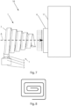
- An alternative spiral shape is shown in fig. 8 .
- the fan provides an airflow into the fluid discharge device.
- the fluid discharge device By providing the fluid discharge device with an air multiplier, a much larger amount of air than the amount of air supplied by the fan, is discharged by the air discharge device. This reduces power-consumption as compared to use of conventional fans directly blowing air. Also, noise emitted from the fan and air multiplier combination is lower than a corresponding noise level emitted from a fan achieving the same air flow.
- Prior art air multipliers are often shaped as rings with a central opening though which air is accelerated by air discharged from the air multiplier. The flow velocity of air flowing through the ring is higher closer to the ring and lower further from the ring.
- the air multiplier By making the air multiplier spiral-shaped, the air multiplier discharges air over a larger portion of the cross-section of the airflow provided by the air discharge device, thereby improving control of flow velocity over the whole cross-section of the airflow emitted by the air discharge device.
- the provision of one spiral-shaped air multiplier enables fluid supply to the air multiplier at one location only, rather than at each separate air multiplier.
- the simplified structure promotes a more even airflow past the air discharge device, since no additional fluid conduits need be provided to each discrete air multiplier.
- the spiral-shaped portion may be substantially planar.
- the fluid discharge device is very compact.
- the spiral-shaped portion may be inclined along the first axis.
- the spiral-shaped portion may be helix-shaped.
- the spiral By arranging the spiral such that it extends in an inclined fashion, a distance between adjacent loops of the spiral will be increased, as compared to a planar spiral. The increased distance enables easier air flow past the fluid discharge device. As seen from one end of the loop, the spiral extends such that the spiral has a component extending along the flow direction axis, thereby contributing to the inclined nature of the spiral-shape.
- the transformer arrangement comprises an airflow generator according to any one of the alternatives defined above, and a transformer provided with an oil-to-air external heat exchanger.
- the airflow generator is configured to discharge air towards the oil-to-air heat exchanger.
- Transformers provided with oil-to-air heat exchangers are known. By providing such transformers with the claimed airflow generator, an energy efficient and compact cooling system for the transformer is achieved.
- Fig. 1 shows a prior art airflow generator comprising an electrically powered ducted fan 2 provided with an inlet 3 and an outlet 4.
- the airflow generator 1 further comprises a fluid conduit 5 and an air multiplier 7 for discharging air along a first axis A.
- the air multiplier 7 comprises an inlet 8 and an outlet.
- the fluid conduit 5 fluidly connects the outlet 4 of the ducted fan 2 to the inlet 8 of the air multiplier 7.
- Air multiplier is used in the prior art and thus should be known to the skilled person.
- Air multipliers are nozzles typically used in bladeless fans.
- the term air multiplier may to refer to any type of air discharge device/nozzle designed to discharge air through an outlet, typically in the form of one or more elongate slits, such that air around the discharge device is brought along by the air discharged from the outlet at a rate of at least 5-15 times the amount of air discharged by the outlet.
- Another term which could be used instead of air multiplier is Coand effect air flow multiplier.
- Such air discharge devices can vary greatly in design but are often shaped like an extruded hollow profile, an example of which is shown in fig. 6 , although any other suitable shape is possible.
- the profile usually has an elongate cross-sectional shape, and the outlet is typically configured to discharge air in a direction along a longitudinal axis extending along the length of the elongate cross-sectional shape, as shown in fig. 6 .
- the profile may have an aerodynamic foil shape.
- the outlet may be provided anywhere suitable along the length of the cross-sectional shape of the profile, such as at a leading portion of the profile (facing incoming ambient air as in fig. 6 ), or at a trailing portion of the profile, facing in the discharge direction of the air multiplier, or somewhere between the leading and trailing portions of the profile.
- the profile may be straight but is typically bent to form a ring circumscribing an inner cross-sectional area of the air multiplier.
- the air multiplier may be provided with a convex curved wall portion wherein the outlet may be provided such that air is discharged adjacent the curved portion, along the curved portion, wherein the discharged air 'adheres' to the curved wall portion. This leads to increased suction effect acting on ambient air on the opposite side of the discharged airflow with respect to the curved wall portion.
- the airflow generator 1 also shown in fig. 1a is shown without the ducted fan 2 and without the fluid conduit 5.
- the fan 2 provides an airflow into the air multiplier 7.
- the ducted nature of the fan 2 enables it to efficiently pressurize the fluid conduit 5.
- an airflow generator 1 By providing the airflow generator 1 with an air multiplier 7, a much larger amount of air than the amount of air supplied by the fan 2, is discharged towards an object, such as the oil-to-air heat exchanger 6 shown in fig. 7 .
- the airflow generator 1 may thus be able to output an airflow of ten to fifteen times the airflow produced by the fan 2. This reduces power-consumption as compared to use of conventional fans directly blowing air against an object to be cooled, such as an oil-to-air heat exchanger 6 provided on a transformer 11.
- Such air multipliers 7 are typically configured as rings with a central opening though which air is moved along by air discharged from the air multiplier along a first axis A.
- the flow velocity of air flowing through the ring is higher closer to the ring and lower further from the ring, as indicated by the broken-line arrows of fig. 1 whose length indicate a strength of local airflow.
- FIG. 2a Another embodiment of a prior art airflow generator is shown in figs. 2a and 2b .
- the airflow generator 1 of figs. 2a and 2b corresponds to the airflow generator 1 of fig. 1 , but is provided with additional air multipliers, provided radially inside of the larger outer air multiplier 7.
- the air multipliers 7, are arranged in a same plane as indicated in fig. 2a .
- the total cross-sectional area inside the larger air multiplier 7 is limited by the thickness of the two inner air multipliers, and only allows air to flow through the passages indicated by arrows d1 and d2.
- the additional inner air multipliers provide increased airflow and improved control of airflow over the cross-sectional area inside the largest air multiplier 7.
- the additional air multipliers lead to reduced energy efficiency of the airflow generator 1.
- the present disclosure proposes to use one air multiplier configured with a spiral shaped portion, as shown in figs. 3a, 3b, 4a, 4b , 5a, and 5b .
- one inlet is sufficient for supplying air into the air multiplier, thereby mitigating the need of additional fluid conduits to supply air to each air multiplier as in the fig. 2a prior art device in which the additional fluid conduits locally restrict airflow and create additional turbulence.
- the spiral shaped portion improves control of the discharged airflow over a greater portion of the cross-sectional area of the discharged airflow as compared to the prior art device of fig. 1a .
- the air multipliers 7, may be configured such that a discharge direction of the air multiplier 7, is parallel to the first axis, or at least essentially parallel to the first axis, such as within a range of 0-20 degrees, or within 0-15 or 0-10 degrees. It should be understood that the local direction of movement of surrounding air moved through the air multipliers (by the Coanda effect), is naturally different from the discharge direction, and locally varies over the cross-section of the airflow generator 1.
- the air multipliers may be shaped from an extruded profile bent to its intended final shape, such a profile will be open ended and thus needs to be closed at any open ends to limit air leaks leading to undesired pressure-drop in the air multiplier 1.
- open ends are capped with an end cap or closed in any other suitable way, such as with a plug.
- a free end of an air multiplier having the cross-sectional shape shown in fig. 5 would have to be closed to enable air to be forced through the outlet opening 9 rather than through the open end.
- the fluid conduit is formed by a portion of a housing in which the ducted fan is provided, wherein the housing forms the duct of the fan and wherein the housing also provided the conduit needed to route air to the inlet of the air multiplier 7.
- the fluid conduit 5 able to route air from the ducted fan to the air multipliers 7, could alternatively be used instead, such as a pipe or tube extending from a ducted fan provided remotely from the air multiplier 7.
- the spiral-shaped portion is substantially planar. By arranging the spiral such that it extends in a plane, the fluid discharge device is very compact.
- the spiral-shaped portion is inclined along the first axis A, either downstream, as shown in fig. 4a , or upstream, as shown in fig. 5a .
- a distance between adjacent loops of the spiral will be increased, as compared to a planar spiral. The increased distance easier air flow past the fluid discharge device.
- the spiral-shaped portion of the embodiments of figs. 4a, 4b , 5a, and 5b is helix-shaped.
- a distance between adjacent loops of the spiral will be increased, as compared to a planar spiral.
- the increased distance enables easier air flow past the fluid discharge device.
- the spiral extends such that the spiral has a component extending along the flow direction axis, thereby contributing to the inclined nature of the spiral-shape.
- the airflow generator 1 of the present disclosure is especially useful for providing an airflow directed towards a heat exchanger 6 mounted externally on a transformer 11. Accordingly, the present disclosure proposes to a transformer arrangement 10 schematically illustrated in fig. 7 .
- the transformer arrangement 10 comprising an airflow generator 1 as described above, comprising an air multiplier 7.
- the transformer arrangement 10 further comprises a transformer 11 provided with an oil-to-air external heat exchanger 6.
- the airflow generator 1 is configured to discharge air towards the oil-to-air heat exchanger 6.
- the oil-to-air external heat exchanger 6 is external in the sense that it is mounted externally on the transformer 11, thereby able to radiate and conduct heat to surrounding air.
- oil from inside the transformer 11 is pumped through the oil-to-air heat exchanger 6, wherein the oil transports heat generated within the transformer 11 out to the heat exchanger 6, such that the airflow from the airflow generator 1 cools the heat exchanger 6.
Landscapes
- Engineering & Computer Science (AREA)
- Power Engineering (AREA)
- Mechanical Engineering (AREA)
- General Engineering & Computer Science (AREA)
- Physics & Mathematics (AREA)
- Fluid Mechanics (AREA)
- Cooling Or The Like Of Electrical Apparatus (AREA)
- Structures Of Non-Positive Displacement Pumps (AREA)
- Wind Motors (AREA)
Abstract
Description
- The present disclosure relates to an airflow generator, and to a transformer assembly comprising such an airflow generator for cooling of a heat exchanger provided externally of the transformer for cooling of the transformer.
- A power transformer is equipment used in an electric grid of a power system. Power transformers transform voltage and current in order to transport and distribute electric energy. Power transformers involve high currents; therefore, production of heat is inevitable. This heat propagates in oil inside a transformer tank. It is important to release this heat to the surroundings for the normal operation of transformers. An important part of oil-cooling is carried out by placing external devices by the transformer, such as radiators, cooler banks etc., through which the transformer oil is circulated and get cooled. State-of-the art air-cooling for a transformer is performed using conventional fans, i.e., bladed fans, or using natural convection. The state-of-the-art cooling systems using bladed fans typically produce high noise, have complex structure, are heavy, and are difficult to maintain. For high-power transformers, natural convection is not enough to cool the transformer, and therefore, forced cooling is needed.
- External transformer cooling generally uses a one or more radiators external to the transformer, said radiators allowing oil to circulate from the transformer and out to the radiators, where heat is dissipated from the oil to surrounding ambient air. The cooling process typically uses natural convection or forced convection to move ambient air past the radiator.
- This disclosure concerns cooling systems using forced convection. Forced convection is typically achieved using one or more large fans blowing air through or onto the radiator(s). Cooling efficiency is dependent on airflow rate and consequently on the power consumption of the fans.
- Accordingly, an object of the present disclosure is to provide a compact and power-efficient airflow generator cooling arrangement for a transformer.
- According to a first aspect of the present disclosure, these and other objects are achieved by an airflow generator as defined in
claim 1, with alternative embodiments defined in dependent claims. The air flow generator is suitable for cooling an oil-to-air external heat exchanger of a transformer. The airflow generator comprises an electrically powered ducted fan provided with an inlet and an outlet, a fluid conduit, and an air multiplier for discharging air along a first axis. The air multiplier comprises an inlet and an outlet. - The fluid conduit fluidly connects the outlet of the ducted fan to the inlet of the air multiplier. The air multiplier comprises a spiral-shaped portion extending around the first axis. The spiral may comprise one or more portions having a smooth curvature, and/or it may comprise one or more straight portions. An alternative spiral shape is shown in
fig. 8 . - The fan provides an airflow into the fluid discharge device. By providing the fluid discharge device with an air multiplier, a much larger amount of air than the amount of air supplied by the fan, is discharged by the air discharge device. This reduces power-consumption as compared to use of conventional fans directly blowing air. Also, noise emitted from the fan and air multiplier combination is lower than a corresponding noise level emitted from a fan achieving the same air flow. Prior art air multipliers are often shaped as rings with a central opening though which air is accelerated by air discharged from the air multiplier. The flow velocity of air flowing through the ring is higher closer to the ring and lower further from the ring.
- By making the air multiplier spiral-shaped, the air multiplier discharges air over a larger portion of the cross-section of the airflow provided by the air discharge device, thereby improving control of flow velocity over the whole cross-section of the airflow emitted by the air discharge device.
- As compared to providing separate concentric air multiplier rings, such as the ones shown in
fig. 2a-b , the provision of one spiral-shaped air multiplier enables fluid supply to the air multiplier at one location only, rather than at each separate air multiplier. The simplified structure promotes a more even airflow past the air discharge device, since no additional fluid conduits need be provided to each discrete air multiplier. - The spiral-shaped portion may be substantially planar.
- By arranging the spiral such that it extends in a plane, the fluid discharge device is very compact.
- The spiral-shaped portion may be inclined along the first axis.
- By arranging the spiral such that it extends in a non-planar fashion, a distance between adjacent loops of the spiral will be increased, as compared to a planar spiral. The increased distance easier air flow past the fluid discharge device,
- To the contrary, the separate air multipliers shown in
figs. 2a-b and lead to a certain degree of constriction of the area available for air to flow through, caused by all air multiplier rings being provided in a same plane (see the limited passage widths indicated by arrows d1 and d2 infig. 2b ). - The spiral-shaped portion may be helix-shaped.
- By arranging the spiral such that it extends in an inclined fashion, a distance between adjacent loops of the spiral will be increased, as compared to a planar spiral. The increased distance enables easier air flow past the fluid discharge device. As seen from one end of the loop, the spiral extends such that the spiral has a component extending along the flow direction axis, thereby contributing to the inclined nature of the spiral-shape.
- According to a second aspect of the present disclosure, these and other objects may be achieved by a transformer arrangement as defined in
claim 10. The transformer arrangement comprises an airflow generator according to any one of the alternatives defined above, and a transformer provided with an oil-to-air external heat exchanger. The airflow generator is configured to discharge air towards the oil-to-air heat exchanger. - Transformers provided with oil-to-air heat exchangers are known. By providing such transformers with the claimed airflow generator, an energy efficient and compact cooling system for the transformer is achieved.
-
-
Fig. 1a shows a prior art airflow generator comprising an air multiplier. -
Fig. 1b shows a side view of the prior art airflow generator also shown infig. 1a (shown without the ducted fan and without the fluid conduit). -
Fig. 2a shows another prior art airflow generator plurality of air multipliers concentrically aligned and arranged in a planar fashion. -
Fig. 2b shows a side view of the prior art airflow generator also shown infig. 2a (shown without the ducted fan and without the fluid conduit). -
Fig. 3a shows a first embodiment of an airflow generator according to the present disclosure, provided with an air multiplier comprising a spiral-shaped portion extending around the first axis in a substantially planar fashion. -
Fig. 3b shows a side view of airflow generator also shown infig. 3a . -
Fig. 4a shows a second embodiment of an airflow generator according to the present disclosure, provided with an air multiplier comprising a spiral-shaped portion extending around the first axis and being inclined along the first axis in a downstream direction. -
Fig. 4b shows a side view of airflow generator also shown infig. 4a . -
Fig. 5a shows a second embodiment of an airflow generator according to the present disclosure, provided with an air multiplier comprising a spiral-shaped portion extending around the first axis and being inclined along the first axis in an upstream direction. -
Fig. 5b shows a side view of airflow generator also shown infig. 4a . -
Fig. 6 shows a perspective view of a cross-section of one of the air multipliers. All air multipliers are based on the same general cross-sectional design. -
Fig. 7 shows a transformer arrangement comprising the airflow generator also shown infig. 4a , and a transformer provided with an external oil-to-air heat exchanger. -
Fig. 8 shows an alternative shape of the spiral-shape of the air multiplier, having a combination of straight portions and rounded corners. - Embodiments of the present disclosure will hereinafter be explained with reference to the appended drawings.
-
Fig. 1 shows a prior art airflow generator comprising an electrically poweredducted fan 2 provided with aninlet 3 and anoutlet 4. Theairflow generator 1 further comprises afluid conduit 5 and anair multiplier 7 for discharging air along a first axis A. Theair multiplier 7 comprises aninlet 8 and an outlet. Thefluid conduit 5 fluidly connects theoutlet 4 of theducted fan 2 to theinlet 8 of theair multiplier 7. - The term air multiplier is used in the prior art and thus should be known to the skilled person. Air multipliers are nozzles typically used in bladeless fans. Herein, the term air multiplier may to refer to any type of air discharge device/nozzle designed to discharge air through an outlet, typically in the form of one or more elongate slits, such that air around the discharge device is brought along by the air discharged from the outlet at a rate of at least 5-15 times the amount of air discharged by the outlet. Another term which could be used instead of air multiplier is Coandeffect air flow multiplier. Such air discharge devices can vary greatly in design but are often shaped like an extruded hollow profile, an example of which is shown in

fig. 6 , although any other suitable shape is possible. The profile usually has an elongate cross-sectional shape, and the outlet is typically configured to discharge air in a direction along a longitudinal axis extending along the length of the elongate cross-sectional shape, as shown infig. 6 . The profile may have an aerodynamic foil shape. The outlet may be provided anywhere suitable along the length of the cross-sectional shape of the profile, such as at a leading portion of the profile (facing incoming ambient air as infig. 6 ), or at a trailing portion of the profile, facing in the discharge direction of the air multiplier, or somewhere between the leading and trailing portions of the profile. The profile may be straight but is typically bent to form a ring circumscribing an inner cross-sectional area of the air multiplier. - The air multiplier may be provided with a convex curved wall portion wherein the outlet may be provided such that air is discharged adjacent the curved portion, along the curved portion, wherein the discharged air 'adheres' to the curved wall portion. This leads to increased suction effect acting on ambient air on the opposite side of the discharged airflow with respect to the curved wall portion.
- In
fig. 1b , theairflow generator 1 also shown infig. 1a is shown without theducted fan 2 and without thefluid conduit 5. - The
fan 2 provides an airflow into theair multiplier 7. The ducted nature of thefan 2 enables it to efficiently pressurize thefluid conduit 5. By providing theairflow generator 1 with anair multiplier 7, a much larger amount of air than the amount of air supplied by thefan 2, is discharged towards an object, such as the oil-to-air heat exchanger 6 shown infig. 7 . Depending on the specific design of theair multiplier 7, theairflow generator 1 may thus be able to output an airflow of ten to fifteen times the airflow produced by thefan 2. This reduces power-consumption as compared to use of conventional fans directly blowing air against an object to be cooled, such as an oil-to-air heat exchanger 6 provided on atransformer 11. -
Such air multipliers 7 are typically configured as rings with a central opening though which air is moved along by air discharged from the air multiplier along a first axis A. The flow velocity of air flowing through the ring is higher closer to the ring and lower further from the ring, as indicated by the broken-line arrows offig. 1 whose length indicate a strength of local airflow. - Another embodiment of a prior art airflow generator is shown in
figs. 2a and 2b . - The
airflow generator 1 offigs. 2a and 2b corresponds to theairflow generator 1 offig. 1 , but is provided with additional air multipliers, provided radially inside of the largerouter air multiplier 7. Theair multipliers 7, are arranged in a same plane as indicated infig. 2a . As shown infig. 2b , the total cross-sectional area inside thelarger air multiplier 7 is limited by the thickness of the two inner air multipliers, and only allows air to flow through the passages indicated by arrows d1 and d2. The additional inner air multipliers, provide increased airflow and improved control of airflow over the cross-sectional area inside thelargest air multiplier 7. However, the additional air multipliers, lead to reduced energy efficiency of theairflow generator 1. - To improve energy efficiency whilst allowing improved control of the discharged airflow, the present disclosure proposes to use one air multiplier configured with a spiral shaped portion, as shown in
figs. 3a, 3b, 4a, 4b ,5a, and 5b . - By making the air multiplier spiral shaped, one inlet is sufficient for supplying air into the air multiplier, thereby mitigating the need of additional fluid conduits to supply air to each air multiplier as in the
fig. 2a prior art device in which the additional fluid conduits locally restrict airflow and create additional turbulence. The spiral shaped portion improves control of the discharged airflow over a greater portion of the cross-sectional area of the discharged airflow as compared to the prior art device offig. 1a . - The
air multipliers 7, may be configured such that a discharge direction of theair multiplier 7, is parallel to the first axis, or at least essentially parallel to the first axis, such as within a range of 0-20 degrees, or within 0-15 or 0-10 degrees. It should be understood that the local direction of movement of surrounding air moved through the air multipliers (by the Coanda effect), is naturally different from the discharge direction, and locally varies over the cross-section of theairflow generator 1. - Since the air multipliers may be shaped from an extruded profile bent to its intended final shape, such a profile will be open ended and thus needs to be closed at any open ends to limit air leaks leading to undesired pressure-drop in the
air multiplier 1. Normally, such open ends are capped with an end cap or closed in any other suitable way, such as with a plug. For example, a free end of an air multiplier having the cross-sectional shape shown infig. 5 , would have to be closed to enable air to be forced through theoutlet opening 9 rather than through the open end. - In the embodiments of
figs. 3a, 3b, 4a, 4b ,5a, and 5b , the fluid conduit is formed by a portion of a housing in which the ducted fan is provided, wherein the housing forms the duct of the fan and wherein the housing also provided the conduit needed to route air to the inlet of theair multiplier 7. Any other configuration of thefluid conduit 5 able to route air from the ducted fan to theair multipliers 7, could alternatively be used instead, such as a pipe or tube extending from a ducted fan provided remotely from theair multiplier 7. - In the embodiment of
figs. 3a and 3b , the spiral-shaped portion is substantially planar. By arranging the spiral such that it extends in a plane, the fluid discharge device is very compact. - In the embodiments of
figs. 4a, 4b ,5a and 5b , the spiral-shaped portion is inclined along the first axis A, either downstream, as shown infig. 4a , or upstream, as shown infig. 5a . By arranging the spiral such that it extends in a non-planar fashion, a distance between adjacent loops of the spiral will be increased, as compared to a planar spiral. The increased distance easier air flow past the fluid discharge device. To the contrary, the separate air multipliers shown infigs. 2a-b and lead to a certain degree of constriction of the area available for air to flow through, caused by all air multiplier rings being provided in a same plane (see the limited passage widths indicated by arrows d1 and d2 infig. 2b ). - The spiral-shaped portion of the embodiments of
figs. 4a, 4b ,5a, and 5b is helix-shaped. By arranging the spiral such that it extends in an inclined fashion, a distance between adjacent loops of the spiral will be increased, as compared to a planar spiral. The increased distance enables easier air flow past the fluid discharge device. As seen from one end of the loop, the spiral extends such that the spiral has a component extending along the flow direction axis, thereby contributing to the inclined nature of the spiral-shape. - The
airflow generator 1 of the present disclosure is especially useful for providing an airflow directed towards aheat exchanger 6 mounted externally on atransformer 11. Accordingly, the present disclosure proposes to atransformer arrangement 10 schematically illustrated infig. 7 . Thetransformer arrangement 10 comprising anairflow generator 1 as described above, comprising anair multiplier 7. Thetransformer arrangement 10 further comprises atransformer 11 provided with an oil-to-airexternal heat exchanger 6. Theairflow generator 1 is configured to discharge air towards the oil-to-air heat exchanger 6. - The oil-to-air
external heat exchanger 6 is external in the sense that it is mounted externally on thetransformer 11, thereby able to radiate and conduct heat to surrounding air. Typically, oil from inside thetransformer 11 is pumped through the oil-to-air heat exchanger 6, wherein the oil transports heat generated within thetransformer 11 out to theheat exchanger 6, such that the airflow from theairflow generator 1 cools theheat exchanger 6.Table of reference numerals 1 airflow generator 2 ducted fan 3 inlet of ducted fan 4 outlet of ducted fan 5 fluid conduit 6 oil-to-air external heat exchanger 7 air multiplier 8 inlet of air multiplier 9 outlet of air multiplier 10 transformer arrangement 11 transformer
Claims (5)
- An airflow generator (1) comprising:an electrically powered ducted fan (2) provided with an inlet (3) and an outlet (4),a fluid conduit (5); andan air multiplier (7) for discharging air along a first axis (A), said air multiplier (7) comprising an inlet (8) and an outlet (9),said fluid conduit (5) fluidly connecting the outlet (4) of the ducted fan (2) to the inlet (8) of the air multiplier (7),wherein the air multiplier (7) comprises a spiral-shaped portion extending around the first axis (A).
- An airflow generator (1) according to claim 1, wherein the spiral-shaped portion is substantially planar.
- An airflow generator (1) according to claim 1, wherein the spiral-shaped portion is inclined along the first axis (A).
- An airflow generator (1) according to claim 1 or 3, wherein the spiral-shaped portion is helix-shaped.
- A transformer arrangement (10) comprising an airflow generator (1) according to any one of claims 1-4, and a transformer (11) provided with an oil-to-air external heat exchanger (6), said airflow generator (1) being configured to discharge air towards the oil-to-air heat exchanger (6).
Priority Applications (4)
| Application Number | Priority Date | Filing Date | Title |
|---|---|---|---|
| EP23156276.0A EP4415007A1 (en) | 2023-02-13 | 2023-02-13 | An airflow generator |
| CN202480010161.0A CN120569792A (en) | 2023-02-13 | 2024-01-17 | Air flow generator |
| PCT/EP2024/051048 WO2024170196A1 (en) | 2023-02-13 | 2024-01-17 | An airflow generator |
| KR1020257025255A KR20250126837A (en) | 2023-02-13 | 2024-01-17 | airflow generator |
Applications Claiming Priority (1)
| Application Number | Priority Date | Filing Date | Title |
|---|---|---|---|
| EP23156276.0A EP4415007A1 (en) | 2023-02-13 | 2023-02-13 | An airflow generator |
Publications (1)
| Publication Number | Publication Date |
|---|---|
| EP4415007A1 true EP4415007A1 (en) | 2024-08-14 |
Family
ID=85227220
Family Applications (1)
| Application Number | Title | Priority Date | Filing Date |
|---|---|---|---|
| EP23156276.0A Pending EP4415007A1 (en) | 2023-02-13 | 2023-02-13 | An airflow generator |
Country Status (4)
| Country | Link |
|---|---|
| EP (1) | EP4415007A1 (en) |
| KR (1) | KR20250126837A (en) |
| CN (1) | CN120569792A (en) |
| WO (1) | WO2024170196A1 (en) |
Citations (2)
| Publication number | Priority date | Publication date | Assignee | Title |
|---|---|---|---|---|
| US20190280562A1 (en) * | 2016-01-20 | 2019-09-12 | Soliton Holdings Corporation, Delaware Corporation | Generalized Jet-Effect and Generalized Generator |
| US20190280561A1 (en) * | 2016-01-20 | 2019-09-12 | Soliton Holdings Corporation, Delaware Corporation | Generalized Jet-Effect and Method for Computational Fluid Dynamics |
Family Cites Families (3)
| Publication number | Priority date | Publication date | Assignee | Title |
|---|---|---|---|---|
| GB2468312A (en) * | 2009-03-04 | 2010-09-08 | Dyson Technology Ltd | Fan assembly |
| JP5829694B2 (en) * | 2010-12-10 | 2015-12-09 | ソリトン ホールディングス コーポレーション, デラウェア コーポレーション | Use of wind power to recover water from the atmosphere |
| CN107747770B (en) * | 2017-09-28 | 2024-03-19 | 青岛海尔空调器有限总公司 | Wall mounted air conditioner indoor unit |
-
2023
- 2023-02-13 EP EP23156276.0A patent/EP4415007A1/en active Pending
-
2024
- 2024-01-17 KR KR1020257025255A patent/KR20250126837A/en active Pending
- 2024-01-17 WO PCT/EP2024/051048 patent/WO2024170196A1/en not_active Ceased
- 2024-01-17 CN CN202480010161.0A patent/CN120569792A/en active Pending
Patent Citations (2)
| Publication number | Priority date | Publication date | Assignee | Title |
|---|---|---|---|---|
| US20190280562A1 (en) * | 2016-01-20 | 2019-09-12 | Soliton Holdings Corporation, Delaware Corporation | Generalized Jet-Effect and Generalized Generator |
| US20190280561A1 (en) * | 2016-01-20 | 2019-09-12 | Soliton Holdings Corporation, Delaware Corporation | Generalized Jet-Effect and Method for Computational Fluid Dynamics |
Also Published As
| Publication number | Publication date |
|---|---|
| WO2024170196A1 (en) | 2024-08-22 |
| CN120569792A (en) | 2025-08-29 |
| KR20250126837A (en) | 2025-08-25 |
Similar Documents
| Publication | Publication Date | Title |
|---|---|---|
| CN103548274B (en) | For cooling down cooling system and the method for radio unit | |
| US9768667B2 (en) | Electric motor with outer radiator and two separate cooling circuits | |
| CA3116099C (en) | Transformer cooling system and transformer installation | |
| US9991759B2 (en) | Multi-directional air cooling of a motor using radially mounted fan and axial/circumferential cooling fins | |
| EP4415006B1 (en) | An airflow generator | |
| US8091376B2 (en) | Bent coil for ducted unit | |
| WO2024170196A1 (en) | An airflow generator | |
| EP4549745B1 (en) | An airflow generator | |
| KR102966584B1 (en) | airflow generator | |
| US7481619B2 (en) | Extended venturi fan ring | |
| EP4421832A1 (en) | A transformer arrangement | |
| CN209571990U (en) | Photovoltaic modules | |
| CN219677256U (en) | Temperature regulating device | |
| CN223077248U (en) | Protective cover structure of condenser and new energy vehicle-mounted refrigerator | |
| CN220135719U (en) | Heat exchanger | |
| KR102839597B1 (en) | Cooling device and method for cooling at least one oil-air external heat exchanger | |
| US20250088066A1 (en) | Airfoil fins for the passive cooling of electronic devices | |
| CN111313829A (en) | Photovoltaic module | |
| CN109786344B (en) | A pressurized heat sink and heat dissipation module | |
| EP3770929A1 (en) | Transformer cooling system | |
| CN120786792A (en) | Composite printed circuit board with heat dissipation channel and heat dissipation method thereof | |
| KR20250088551A (en) | Cooling device and method for cooling at least one oil-air external heat exchanger |
Legal Events
| Date | Code | Title | Description |
|---|---|---|---|
| PUAI | Public reference made under article 153(3) epc to a published international application that has entered the european phase |
Free format text: ORIGINAL CODE: 0009012 |
|
| STAA | Information on the status of an ep patent application or granted ep patent |
Free format text: STATUS: THE APPLICATION HAS BEEN PUBLISHED |
|
| AK | Designated contracting states |
Kind code of ref document: A1 Designated state(s): AL AT BE BG CH CY CZ DE DK EE ES FI FR GB GR HR HU IE IS IT LI LT LU LV MC ME MK MT NL NO PL PT RO RS SE SI SK SM TR |
|
| STAA | Information on the status of an ep patent application or granted ep patent |
Free format text: STATUS: REQUEST FOR EXAMINATION WAS MADE |
|
| 17P | Request for examination filed |
Effective date: 20250214 |
|
| RIN1 | Information on inventor provided before grant (corrected) |
Inventor name: SAND, ULF Inventor name: HOSAIN, LOKMAN Inventor name: BEL FDHILA, REBEI |