EP4414919A1 - Method for configuring a water distribution network during leak repair - Google Patents
Method for configuring a water distribution network during leak repair Download PDFInfo
- Publication number
- EP4414919A1 EP4414919A1 EP23156063.2A EP23156063A EP4414919A1 EP 4414919 A1 EP4414919 A1 EP 4414919A1 EP 23156063 A EP23156063 A EP 23156063A EP 4414919 A1 EP4414919 A1 EP 4414919A1
- Authority
- EP
- European Patent Office
- Prior art keywords
- bypass
- distribution network
- water distribution
- penalty
- configuration
- Prior art date
- Legal status (The legal status is an assumption and is not a legal conclusion. Google has not performed a legal analysis and makes no representation as to the accuracy of the status listed.)
- Granted
Links
Images

Classifications
-
- G—PHYSICS
- G06—COMPUTING OR CALCULATING; COUNTING
- G06Q—INFORMATION AND COMMUNICATION TECHNOLOGY [ICT] SPECIALLY ADAPTED FOR ADMINISTRATIVE, COMMERCIAL, FINANCIAL, MANAGERIAL OR SUPERVISORY PURPOSES; SYSTEMS OR METHODS SPECIALLY ADAPTED FOR ADMINISTRATIVE, COMMERCIAL, FINANCIAL, MANAGERIAL OR SUPERVISORY PURPOSES, NOT OTHERWISE PROVIDED FOR
- G06Q50/00—Information and communication technology [ICT] specially adapted for implementation of business processes of specific business sectors, e.g. utilities or tourism
- G06Q50/06—Energy or water supply
-
- G—PHYSICS
- G06—COMPUTING OR CALCULATING; COUNTING
- G06Q—INFORMATION AND COMMUNICATION TECHNOLOGY [ICT] SPECIALLY ADAPTED FOR ADMINISTRATIVE, COMMERCIAL, FINANCIAL, MANAGERIAL OR SUPERVISORY PURPOSES; SYSTEMS OR METHODS SPECIALLY ADAPTED FOR ADMINISTRATIVE, COMMERCIAL, FINANCIAL, MANAGERIAL OR SUPERVISORY PURPOSES, NOT OTHERWISE PROVIDED FOR
- G06Q10/00—Administration; Management
- G06Q10/20—Administration of product repair or maintenance
Definitions
- the invention relates to repair work in water distribution networks that supply water from at least one water source to a plurality of customers.
- the invention provides a computer-implemented method for determining a configuration of a water distribution network.
- the water distribution network is to supply water from at least one water source, such as water works or a service reservoir, to a plurality of customers.
- the sought configuration is to keep a given leak in the water distribution network isolated, i.e., disconnected from all water sources. At the same time, interruption of supply to customers is to be reduced.
- the method starts from a base configuration where the given leak is isolated.
- Obtaining such a base configuration i.e., isolating a recently identified leak, is standard practice for any operator of a water distribution network.
- a hydraulic model of the water distribution network in this base configuration is provided.
- a hydraulic model of the water distribution network in the ideal, leak-less state may be kept ready and quickly adapted to account for an identified leak.
- a hydraulic model may model the behavior of water that is propagated from one or more water sources through the water distribution network and optionally accelerated and/or pressurized with one or more pumps.
- the behavior of the water at a particular point in the water distribution network may be characterized by flows on the one hand and pressures (or heads that are a different notion of pressures) on the other hand.
- bypass components may comprise pipes, hoses and/or pumps with which temporary connections may be made between junctions in the network. Pumps are needed if the destination of the temporary connection has a higher elevation than the source, and/or if a purely gravitation-driven flow of water will not cause a sufficient quantity of water to flow.
- each bypass component does not come automatically and effortlessly. Rather, installation and/or usage of each bypass component is associated with a penalty value.
- This penalty value may, e.g., represent a monetary cost, and/or a cost in terms of time, personnel or any other resource. The only requirement for the penalty value is that it can somehow be compared with penalty values that are associated with supply interruption of particular customers during isolation of the leak. Such a penalty value is provided for each customer of the water distribution network. Penalty values are needed as feedback for the optimization of the configuration of the water distribution network by means of bypass connections.
- pairs (i,j) of junctions i and j in the water distribution network that are connectable with bypass connections using bypass components without reconnecting the leak to a water source are determined. For a given pair ( i,j ), it is easy to check whether this requirement is met. If junction i is connected to a water source, and junction j is connected to the leak (or vice versa), then activating the bypass connection between junctions i and j will compromise the isolation of the leak, which precludes activating this bypass connection.
- Additive penalty contributions for installation and/or usage of such bypass connections are determined. This is what needs to be invested into the bypass connections.
- the penalty values for installation and/or usage of each bypass component used in the bypass connections may be determined based at least in part on the penalty values retrieved from the inventory of bypass components. But the penalty value may also, for example, depend on the concrete location where the bypass component is to be installed. For example, it is more difficult to deploy a bypass connection through a river than on land.
- bypass connections interact with the rest of the water distribution network according to the given hydraulic model, as well as with each other.
- a flow q ij through a bypass connection from junction i to junction j which the bypass components themselves could support in principle, is only possible if a sufficient quantity of water is available at junction i , and if there is sufficient capacity in the system to carry this quantity of water away from junction j .
- a liquid as the conveyed medium this is literally a harder condition than with a gas as the conveyed medium because liquids are basically incompressible.
- an equation is set up.
- the equation comprises at least the flow q ij through the bypass connection and the switching state s ij of the bypass connection as variables.
- there may be more variables such as set-points for controllable elements, e.g., rotational speeds of pumps.
- the equations may also comprise variables pertaining to other parts of the water distribution network that were already present in the base configuration.
- the equations may comprise flows and switching states of such parts as well.
- the head h i , h j is a notion of the pressure and has the dimension of a height. This is the height to which the pressure at the junction i would be able to push the water. If the connection from junction i to junction j is open, then the head difference needs to obey the continuity function ⁇ h ij ( q ij ) because water is neither created nor destroyed in the bypass connection. If the bypass connection is closed, there may be any head h i at junction i, but junction j may not know about that, for want of the bypass connection. But this also means that there can be no flow q ij across the bypass connection.
- the so-obtained set of flows q ij and switching states s ij is determined as the sought configuration of the water distribution network. If the system of equations comprises other switching states and continuous quantities of the water distribution network as variables, the solved values of these variables form part of the sought configuration of the water distribution network as well. That is, if, starting from the base configuration, the bypass connections are established as per the result of the optimization, the penalty value will be lower compared with the original base configuration. If the equations also cover at least some switching states and configuration parameters of the base configuration of the water distribution network, this base configuration may be optimized as well. For example, by intelligently choosing how to isolate the leak, supply interruptions and a need to deploy bypass connections may be minimized from the start.
- bypass connections need to be physically installed. For example, only bypass connections which are to be switched on and have nonzero flows q ij at least for some of the time may need to be installed in the first place. Also, from the flows q ij , it can be inferred how large the throughput of the bypass connection needs to be.
- the optimization problem comprises a mixture of discrete variables, such as switching states s ij , and continuous variables, such as flows q ij .
- the optimization problem is approximated by a problem having only continuous variables. This entails sacrificing some accuracy.
- the speed-up may mean that, given a certain budget of computation time, the approximation may yield a better end result than an attempt to solve the original problem.
- the condition for the head h i at junction i and the head h j at junction j is relaxed such that the difference h i - h j may deviate from the value of the given continuity function ⁇ h ij ( q ij ) by an amount that is bounded by - s ij ⁇ and s ij + .
- the optimizing of the approximated problem comprises minimizing the products s ij + q ij and s ij ⁇ q ij . Ideally, these products should be zero. If the bypass connection is closed, then this zero is actually attained. If the bypass connection is open, the bigger the flow q ij is, the smaller the nonzero values of s ij + and s ij ⁇ become. This means that for smaller flows q ij , a larger relaxation of the original problem is allowed because the inaccuracy can only make up a small quantity of water anyway, whereas a higher accuracy is demanded where larger flows q ij are involved.
- a Hazen-Williams model ⁇ h ij ( q ij ) r q ij q ij n ⁇ 1 + m q ij q ij , with head loss coefficients r and m and flow exponent n, is chosen as the given continuity function ⁇ h ij ( q ij ).
- This model allows to consider physical properties of the bypass connections and a head loss due to friction. In this manner, it can be considered that different bypass connections have different physical properties.
- At least one penalty contribution for installation of a bypass connection is approximated by a penalty contribution for usage of this bypass connection.
- the to-be-used bypass connections are filtered according to a predetermined criterion.
- the optimization is then repeated under the constraint that the to-be-used bypass connections are fixed. In this manner, the number of to-be-used bypass connections can be reduced to a level that is deemed to be practical for physical deployment.
- the second round of optimization may then, for example, yield modifications to operating parameters that can at least partially make up for the missing bypass connections.
- a Top-N selection of bypass connections may be made to account for a limited number of field teams that are available to deploy bypass connections.
- the predetermined criterion for the filtering may comprise whether the flow q ij through the bypass connection is above a given threshold value. For example, the numerical optimization might converge to a solution where a lot of flows q ij have very small but nonzero values (say, 1 liter per hour). These small flows are of no practical significance for restoring supply to customers and can simply be dropped.
- the flow q ij through each bypass connection is bounded by a maximum value q ij max .
- the bypass connections are temporary connections that have a lesser throughput than the regular connections in the water distribution network.
- At least one penalty contribution is time-dependent.
- the optimizing is also performed with respect to a time or timeframe for isolating the leak. In this manner, the total penalty may be reduced further by rescheduling the repair work. For example, industrial customers who are cut off from supply may suffer a much higher penalty at daytime than at nighttime or on weekends when no one is working there. But on the other hand, field teams for deploying bypass connections carry a higher penalty in terms of expense during these times.
- hydraulic models are provided for multiple candidate base configurations in which the leak is isolated.
- an optimization is performed , for a set of flows q ij and switching states s ij of bypass connections.
- the combination of the candidate base configuration and the set of flows q ij * and switching states s ij * for which the lowest penalty is obtained is determined as the sought configuration of the water distribution network.
- the finding of an optimal base configuration for initially isolating the leak may be integrated with the finding of an optimal bypass configuration, so that a lesser overall penalty may be achieved.
- the optimal base configuration for isolating the leak and the optimal bypass configuration are not fully independent:
- a given base configuration may be very beneficial if sufficient material and personnel is available for deploying a certain number of bypass connections.
- the very same base configuration may become disadvantageous by virtue of only insufficient material and personnel for bypass connections being available, which causes some important customers to remain without supply and the overall penalty to skyrocket.
- the possible number of candidate base configurations is typically rather small because there are only a few distinct possibilities to physically close off the leak from any water sources.
- the method further comprises physically configuring the water distribution network according to the configuration determined by the optimization.
- the benefit of a low penalty that the optimization promises for the determined configuration is actually put into practice.
- the method as a whole is a computer-implemented method shall not be construed to mean that each and every step of physically implementing the determined configuration on the water distribution network needs to be done by the computer as well. Some actions, like assembling temporary bypass connections, will need to be performed outside the computer. But the computer can then, for example, still control switching states of bypass connections or speeds of pumps feeding the bypass connections. Also, depending on the concrete water distribution network at hand, the physical setting of the base configuration to isolate the leak may be performed in a computer-controlled manner by sending commands to computer-controlled valves.
- the present method may be embodied in the form of a software.
- the invention therefore also relates to a computer program with machine-readable instructions that, when executed by one or more computers and/or compute instances, cause the one or more computers and/or compute instances to perform the method described above.
- Examples for compute instances include virtual machines, containers or serverless execution environments in a cloud.
- the invention also relates to a machine-readable data carrier and/or a download product with the computer program.
- a download product is a digital product with the computer program that may, e.g., be sold in an online shop for immediate fulfilment and download to one or more computers.
- the invention also relates to one or more compute instances with the computer program, and/or with the machine-readable data carrier and/or download product.
- Figure 1 is a schematic flow chart of an embodiment of the method 100 for determining a configuration 1* of a water distribution network 1 to partially relieve the effects of isolating a leak 1a.
- the method starts from a situation where a water distribution network 1 with at least one water source 2 and customers 3 is given, and there is a leak 1a in a known place in the water distribution network 1.
- a hydraulic model 1b of the water distribution network 1 is provided.
- This hydraulic model 1b relates to a base configuration of the water distribution network 1 where the given leak 1a is isolated.
- multiple hydraulic models 1b may be provided for multiple candidate base configurations in which the leak 1a is isolated.
- step 120 an inventory of available bypass components 4 is provided. Installation and/or usage of each bypass component 4 is associated with a penalty value 4a.
- step 130 for each customer 3 of the water distribution network 1, a penalty value 3a that is associated with supply interruption of this customer 3 during isolation of the leak 1a is provided.
- each bypass connection 4# may be made of multiple bypass components 4.
- the possible bypass connections 4# correspond to pairs ( i,j ) of junctions i and j in the water distribution network 1 that are connectable with bypass components 4 without reconnecting the leak 1a to a water source 2.
- Installation and/or usage of each bypass connection 4# carries an additive penalty contribution 5+.
- reconnection of customers to a water source 2 by virtue of the bypass connection 4# carries a subtractive penalty contribution 5-, i.e., a reward.
- At least one penalty contribution 5+ for installation of a bypass connection 4# may be approximated by a penalty contribution for usage of this bypass connection 4#, to avoid problems of some optimization algorithms when handling usage-independent penalty contributions.
- At least one penalty contribution 5+, 5- may be time-dependent.
- step 150 for each pair ( i,j ) of junctions i and j that is connectable by a bypass connection 4#, at least one equation 6 is set up.
- the equation 6 has at least the flow q ij through the bypass connection 4# and the switching state s ij of the bypass connection 4# as variables.
- the equation 6 stipulates that, of the conditions:
- the flow q ij through each bypass connection may be bounded by a maximum value q ij max .
- step 160 an optimization is performed for a set of flows q ij and switching states s ij that fulfils the system of equations 6 while carrying a low overall penalty.
- This overall penalty is made up from all additive penalty contributions 5+ and subtractive penalty contributions 5-.
- the optimization problem may be approximated by a problem having only continuous variables, so as to provide access to optimization algorithms that work on continuous problems only.
- the discrete switching state s ij of the bypass connection 4# between junctions i and j may be substituted with a pair of continuous switching state variables s ij + ⁇ 0 and s ij ⁇ ⁇ 0 .
- the condition for the head h i at junction i and the head h j at junction j may be relaxed such that the difference h i - h j may deviate from the value of the given continuity function ⁇ h ij ( q ij ) by an amount that is bounded by - s ij ⁇ and s ij + .
- the optimizing of the approximated problem may then comprise minimizing the products s ij + q ij and s ij ⁇ q ij .
- the optimization 160 may also be performed with respect to a time or timeframe for isolating the leak 1a.
- the optimization may be performed separately for each of a plurality of candidate base configurations that are provided according to block 111.
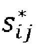
- the optimization 160 yields a set of optimal flows q ij * and a set of optimal switching states s ij * that define to-be-used bypass connections 4##.
- these to-be-used bypass connections 4## may be filtered according to a predetermined criterion 7.
- the predetermined criterion 7 for the filtering may comprise whether the flow q ij through the bypass connection 4# is above a given threshold value.
- step 180 after the filtering, the optimization 160 may be repeated under the constraint that the to-be-used bypass connections 4* are fixed.
- step 190 the finally obtained optimal set of flows q ij * and switching states s ij * , whether obtained through one single optimization 160 or through repeated optimizations 160, is determined as the sought configuration 1* of the water distribution network 1.
- the combination of the candidate base configuration and the set of flows q ij * and switching states s ij * for which the lowest penalty is obtained may be determined as the sought configuration 1* of the water distribution network 1.
- step 200 the water distribution network 1 is configured according to the determined configuration 1*. That is, bypass connections are implemented, and optionally the optimal base configuration for isolating the leak 1a is implemented, so that the optimized low penalty values is actually achieved in operation of the water distribution network 1.
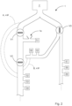
- FIG. 2 illustrates a potential use case of the method 100 on a simple example of a water distribution network 1 .
- the water distribution network 1 comprises one single water source 2 and nine water-consuming customers 3 that are labelled 31-39 to make them distinguishable. Also, three valves V1, V2 and V3 are provided to permit isolating sections of the water distribution network 1 from the water source 2.
- valves V1 and V2 have been closed. This means that not only customer 31, but also customers 32, 33 and 34 are currently without water service. Valve V3 is still open, which means that customers 35 to 39 still have water service.
- FIG. 2 shows two exemplary possibilities A and B how this may be done. Junction places to which bypass components 4 may be attached have been omitted in Figure 2 for clarity.
- water may be taken from the pipe section between the water source 2 and the valve V1 and conveyed through the bypass connection 4# into the pipe section that serves customers 32, 33 and 34.
- water may be taken from the pipe section that serves customers 33 and 34 and conveyed through the bypass connection 4# into the pipe section that serves customers 32, 33 and 34.
- Possibility A permits to convey a larger flow of water because it taps into a rather wide pipe coming from the water source 2, but the bypass connection 4# is long and therefore costly to deploy.
- Possibility B permits to convey the water along a much shorter bypass connection 4#, but the downside is that this connection gets water from a much smaller pipe and can therefore only provide a lower maximum flow to customers 32, 33 and 34.
Landscapes
- Business, Economics & Management (AREA)
- Engineering & Computer Science (AREA)
- Human Resources & Organizations (AREA)
- Economics (AREA)
- Physics & Mathematics (AREA)
- Theoretical Computer Science (AREA)
- Health & Medical Sciences (AREA)
- Marketing (AREA)
- Strategic Management (AREA)
- Tourism & Hospitality (AREA)
- General Physics & Mathematics (AREA)
- General Business, Economics & Management (AREA)
- Entrepreneurship & Innovation (AREA)
- Quality & Reliability (AREA)
- Operations Research (AREA)
- Public Health (AREA)
- Water Supply & Treatment (AREA)
- General Health & Medical Sciences (AREA)
- Primary Health Care (AREA)
- Management, Administration, Business Operations System, And Electronic Commerce (AREA)
- Data Exchanges In Wide-Area Networks (AREA)
Abstract
• providing (110) a hydraulic model (1b) of the water distribution network (1) in a base configuration where the given leak (1a) is isolated;
• providing (120) an inventory of available bypass components (4), wherein installation and/or usage of each bypass component (4) is associated with a penalty value (4a);
• providing (130), for each customer (3) of the water distribution network (1), a penalty value (3a) that is associated with supply interruption of this customer (3) during isolation of the leak (1a);
• determining (140), based on the inventory of available bypass components (4), bypass connections (4#) between junctions i and j in the water distribution network (1), additive penalty contributions (5+) for installation and/or usage of such bypass connections (4#), and subtractive penalty contributions (5-) for reconnection of customers (3) to a water source (2) by virtue of the bypass connections (4#);
• setting up (150), for each such pair (i,j), at least one equation (6), said at least one equation (6) in at least the flow qij through the bypass connection (4#) and the switching state sij of the bypass connection (4#) stipulating that, of the conditions:
∘ the difference hi - hj between the head hi at junction i and the head hj at junction j shall be dependent on the flow qij through the bypass connection according to a given continuity function Δhij (qij ), and
∘ the flow qij shall vanish,
at least one condition is satisfied;
• optimizing (160) for a set of flows qij and switching states sij that fulfils the system of equations (6) while carrying a low overall penalty; and
• determining (190) the obtained set of flows


Description
- The invention relates to repair work in water distribution networks that supply water from at least one water source to a plurality of customers.
- The availability of potable water from the tap in every household and business is a great accomplishment of civilization and has saved lives that were, in former times, lost to diseases that were transmitted by contaminated water. However, installation and maintenance of water distribution networks is costly. Water pipes are buried in the ground for decades and subject to wear and tear. Eventually, leaks develop. Water lost from a leak is an economic loss and can cause further damage if it flows into places that are supposed to be kept dry. Furthermore, leaks open up the water in the pipe to contamination. It is therefore important to repair leaks in a timely manner.
- However, such repair work necessitates isolating the leak, that is, disconnecting the leak from any water source. This comes with its own problems, as at least a part of the network that comprises the leak needs to be taken out of service. Depending on whether it is possible to isolate only a small network portion, hundreds or even thousands of customers may have their supply interrupted. For household customers, this may be just a temporary nuisance, but industrial customers may need to suspend production at a large cost.
- It is therefore an objective of the invention to provide a method for determining a configuration of a water distribution network that will keep a leak isolated for repair work while at the same time reducing interruption of supply to customers.
- This objective is achieved by the method according to the independent claim. Further advantageous embodiments are detailed in the dependent claims.
- The invention provides a computer-implemented method for determining a configuration of a water distribution network. The water distribution network is to supply water from at least one water source, such as water works or a service reservoir, to a plurality of customers. The sought configuration is to keep a given leak in the water distribution network isolated, i.e., disconnected from all water sources. At the same time, interruption of supply to customers is to be reduced.
- The method starts from a base configuration where the given leak is isolated. Obtaining such a base configuration, i.e., isolating a recently identified leak, is standard practice for any operator of a water distribution network.
- A hydraulic model of the water distribution network in this base configuration is provided. To this end, for example, a hydraulic model of the water distribution network in the ideal, leak-less state may be kept ready and quickly adapted to account for an identified leak. In particular, a hydraulic model may model the behavior of water that is propagated from one or more water sources through the water distribution network and optionally accelerated and/or pressurized with one or more pumps. In particular, the behavior of the water at a particular point in the water distribution network may be characterized by flows on the one hand and pressures (or heads that are a different notion of pressures) on the other hand.
- An inventory of available bypass components, is provided. This inventory may, for example, be a database system that keeps track of the location at which each bypass component is stored, as well as of the capabilities of each bypass component and the possibilities for connecting bypass components together. In particular, bypass components may comprise pipes, hoses and/or pumps with which temporary connections may be made between junctions in the network. Pumps are needed if the destination of the temporary connection has a higher elevation than the source, and/or if a purely gravitation-driven flow of water will not cause a sufficient quantity of water to flow.
- Of course, installation and/or usage of each bypass component does not come automatically and effortlessly. Rather, installation and/or usage of each bypass component is associated with a penalty value. This penalty value may, e.g., represent a monetary cost, and/or a cost in terms of time, personnel or any other resource. The only requirement for the penalty value is that it can somehow be compared with penalty values that are associated with supply interruption of particular customers during isolation of the leak. Such a penalty value is provided for each customer of the water distribution network. Penalty values are needed as feedback for the optimization of the configuration of the water distribution network by means of bypass connections.
- Based on the inventory of available bypass components, pairs (i,j) of junctions i and j in the water distribution network that are connectable with bypass connections using bypass components without reconnecting the leak to a water source are determined. For a given pair (i,j), it is easy to check whether this requirement is met. If junction i is connected to a water source, and junction j is connected to the leak (or vice versa), then activating the bypass connection between junctions i and j will compromise the isolation of the leak, which precludes activating this bypass connection.
- Additive penalty contributions for installation and/or usage of such bypass connections are determined. This is what needs to be invested into the bypass connections. The penalty values for installation and/or usage of each bypass component used in the bypass connections may be determined based at least in part on the penalty values retrieved from the inventory of bypass components. But the penalty value may also, for example, depend on the concrete location where the bypass component is to be installed. For example, it is more difficult to deploy a bypass connection through a river than on land.
- On the other hand, subtractive penalty contributions for reconnection of customers to a water source by virtue of the bypass connections are determined. That is, if the network had just been left in its base configuration with the leak isolated and the customer cut off from the supply, then this customer would have suffered/incurred a penalty value. By reconnecting the customer, this penalty value is avoided. This is the return gained from investing into temporary bypass connections. The more customers can be reconnected by a bypass connection and the more urgently they need water (e.g., for hospitals or industrial production processes), the more effort for bypass connections is justified.
- It now needs to be considered that bypass connections interact with the rest of the water distribution network according to the given hydraulic model, as well as with each other. For example, a flow qij through a bypass connection from junction i to junction j, which the bypass components themselves could support in principle, is only possible if a sufficient quantity of water is available at junction i, and if there is sufficient capacity in the system to carry this quantity of water away from junction j. With a liquid as the conveyed medium, this is literally a harder condition than with a gas as the conveyed medium because liquids are basically incompressible.
- To accommodate said interactions, for each pair (i,j), an equation is set up. The equation comprises at least the flow qij through the bypass connection and the switching state sij of the bypass connection as variables. Optionally, there may be more variables, such as set-points for controllable elements, e.g., rotational speeds of pumps. The equations may also comprise variables pertaining to other parts of the water distribution network that were already present in the base configuration. There may also be equations that solely relate to parts of the base configuration of the water distribution network. In particular, the equations may comprise flows and switching states of such parts as well.
- Regarding the bypass connections, the equations stipulate that at least one of the following conditions is satisfied:
- The difference hi - hj between the head hi at junction i and the head hj at junction j shall be dependent on the flow qij through the bypass connection according to a given continuity function Δhij (qij ), and/or
- the flow qij shall vanish.
- The head hi , hj is a notion of the pressure and has the dimension of a height. This is the height to which the pressure at the junction i would be able to push the water. If the connection from junction i to junction j is open, then the head difference needs to obey the continuity function Δhij (qij ) because water is neither created nor destroyed in the bypass connection. If the bypass connection is closed, there may be any head hi at junction i, but junction j may not know about that, for want of the bypass connection. But this also means that there can be no flow qij across the bypass connection.
- An optimization is now performed for a set of flows qij and switching states sij that fulfils the system of equations while carrying a low overall penalty. The so-obtained set of flows qij and switching states sij is determined as the sought configuration of the water distribution network. If the system of equations comprises other switching states and continuous quantities of the water distribution network as variables, the solved values of these variables form part of the sought configuration of the water distribution network as well. That is, if, starting from the base configuration, the bypass connections are established as per the result of the optimization, the penalty value will be lower compared with the original base configuration. If the equations also cover at least some switching states and configuration parameters of the base configuration of the water distribution network, this base configuration may be optimized as well. For example, by intelligently choosing how to isolate the leak, supply interruptions and a need to deploy bypass connections may be minimized from the start.
- It was found that in this manner, a solution that is significantly better than the base configuration can be obtained rather quickly. It is not guaranteed that a global optimum will be reached quickly, or that this will be reached at all. But this is not of prime importance in the application at hand. Here, the solution is to get a working solution that is better than the original base configuration in a short time. When a leak is discovered, it may need to be isolated immediately to avoid further damage. With every minute of waiting for the plan how to reconnect a part of the customers, a part of the potential benefit of having this plan vanishes. If computation of the plan takes longer than the entire service interruption lasts, the computation is futile altogether.
- From the determined switching states sij and flows qij of bypass connections, it can be inferred which bypass connections need to be physically installed. For example, only bypass connections which are to be switched on and have nonzero flows qij at least for some of the time may need to be installed in the first place. Also, from the flows qij , it can be inferred how large the throughput of the bypass connection needs to be.
- One property of the optimization problem that costs time is that the problem comprises a mixture of discrete variables, such as switching states sij , and continuous variables, such as flows qij . This precludes the use of very fast algorithms that are available for the solving of purely continuous problems. Thinking of the problem as a ship, it is too big to pass the Panama Canal, so it must go all the way around South America to cross from the Atlantic Ocean into the Pacific Ocean. Therefore, in a particularly advantageous embodiment, the optimization problem is approximated by a problem having only continuous variables. This entails sacrificing some accuracy. But since the factor of time is also important, the speed-up may mean that, given a certain budget of computation time, the approximation may yield a better end result than an attempt to solve the original problem.
- One particularly advantageous way to approximate the optimization problem comprises, for each pair (i,j) of junctions: substituting the discrete switching state sij of the bypass connection between junctions i and j with a pair of continuous switching state variables


- In a further particularly advantageous embodiment, the optimizing of the approximated problem comprises minimizing the products


- In a further advantageous embodiment, a Hazen-Williams model Δhij (qij ) =

- In a further particularly advantageous embodiment, at least one penalty contribution for installation of a bypass connection is approximated by a penalty contribution for usage of this bypass connection. With some otherwise advantageous optimization algorithms, it is difficult to solve problems with fixed penalty contributions that are independent of quantitative usage. The approximation sacrifices some accuracy, but in return allows to use said advantageous algorithms.
- In a further particularly advantageous embodiment, after the optimizing, the to-be-used bypass connections are filtered according to a predetermined criterion. The optimization is then repeated under the constraint that the to-be-used bypass connections are fixed. In this manner, the number of to-be-used bypass connections can be reduced to a level that is deemed to be practical for physical deployment. The second round of optimization may then, for example, yield modifications to operating parameters that can at least partially make up for the missing bypass connections.
- For example, a Top-N selection of bypass connections may be made to account for a limited number of field teams that are available to deploy bypass connections. In another example, the predetermined criterion for the filtering may comprise whether the flow qij through the bypass connection is above a given threshold value. For example, the numerical optimization might converge to a solution where a lot of flows qij have very small but nonzero values (say, 1 liter per hour). These small flows are of no practical significance for restoring supply to customers and can simply be dropped.
- In another advantageous embodiment, the flow qij through each bypass connection is bounded by a maximum value

- In a further particularly advantageous embodiment, at least one penalty contribution is time-dependent. The optimizing is also performed with respect to a time or timeframe for isolating the leak. In this manner, the total penalty may be reduced further by rescheduling the repair work. For example, industrial customers who are cut off from supply may suffer a much higher penalty at daytime than at nighttime or on weekends when no one is working there. But on the other hand, field teams for deploying bypass connections carry a higher penalty in terms of expense during these times.
- In a further particularly advantageous embodiment, hydraulic models are provided for multiple candidate base configurations in which the leak is isolated. For each such candidate base configuration, an optimization is performed , for a set of flows qij and switching states sij of bypass connections. The combination of the candidate base configuration and the set of flows


- At the same time, the possible number of candidate base configurations is typically rather small because there are only a few distinct possibilities to physically close off the leak from any water sources. Thus, rather than extending the numerical optimization to the base configuration, it may be easier to just enumerate the candidate base configurations and perform one numerical optimization for each candidate base configuration.
- In a further advantageous embodiment, the method further comprises physically configuring the water distribution network according to the configuration determined by the optimization. In this manner, the benefit of a low penalty that the optimization promises for the determined configuration is actually put into practice. In this respect, that the method as a whole is a computer-implemented method shall not be construed to mean that each and every step of physically implementing the determined configuration on the water distribution network needs to be done by the computer as well. Some actions, like assembling temporary bypass connections, will need to be performed outside the computer. But the computer can then, for example, still control switching states of bypass connections or speeds of pumps feeding the bypass connections. Also, depending on the concrete water distribution network at hand, the physical setting of the base configuration to isolate the leak may be performed in a computer-controlled manner by sending commands to computer-controlled valves.
- Because it is computer-implemented, the present method may be embodied in the form of a software. The invention therefore also relates to a computer program with machine-readable instructions that, when executed by one or more computers and/or compute instances, cause the one or more computers and/or compute instances to perform the method described above. Examples for compute instances include virtual machines, containers or serverless execution environments in a cloud. The invention also relates to a machine-readable data carrier and/or a download product with the computer program. A download product is a digital product with the computer program that may, e.g., be sold in an online shop for immediate fulfilment and download to one or more computers. The invention also relates to one or more compute instances with the computer program, and/or with the machine-readable data carrier and/or download product.
- In the following, the invention is illustrated using Figures without any intention to limit the scope of the invention. The Figures show:
-
Figure 1 : Exemplary embodiment of themethod 100 for determining aconfiguration 1* of awater distribution network 1 to partially relieve the effects of isolating aleak 1a; -
Figure 2 : Illustration of a potential use case of themethod 100 on a simple example of awater distribution network 1. -
Figure 1 is a schematic flow chart of an embodiment of themethod 100 for determining aconfiguration 1* of awater distribution network 1 to partially relieve the effects of isolating aleak 1a. The method starts from a situation where awater distribution network 1 with at least onewater source 2 and customers 3 is given, and there is aleak 1a in a known place in thewater distribution network 1. - In
step 110, ahydraulic model 1b of thewater distribution network 1 is provided. Thishydraulic model 1b relates to a base configuration of thewater distribution network 1 where the givenleak 1a is isolated. - According to block 111, multiple
hydraulic models 1b may be provided for multiple candidate base configurations in which theleak 1a is isolated. - In
step 120, an inventory ofavailable bypass components 4 is provided. Installation and/or usage of eachbypass component 4 is associated with a penalty value 4a. - In
step 130, for each customer 3 of thewater distribution network 1, apenalty value 3a that is associated with supply interruption of this customer 3 during isolation of theleak 1a is provided. - In
step 140, based at least in part on the inventory ofavailable bypass components 4,possible bypass connections 4# are determined. In particular, eachbypass connection 4# may be made ofmultiple bypass components 4. Thepossible bypass connections 4# correspond to pairs (i,j) of junctions i and j in thewater distribution network 1 that are connectable withbypass components 4 without reconnecting theleak 1a to awater source 2. Installation and/or usage of eachbypass connection 4# carries anadditive penalty contribution 5+. On the other hand, reconnection of customers to awater source 2 by virtue of thebypass connection 4# carries a subtractive penalty contribution 5-, i.e., a reward. - According to block 141, at least one
penalty contribution 5+ for installation of abypass connection 4# may be approximated by a penalty contribution for usage of thisbypass connection 4#, to avoid problems of some optimization algorithms when handling usage-independent penalty contributions. - According to block 142, at least one
penalty contribution 5+, 5- may be time-dependent. - In
step 150, for each pair (i,j) of junctions i and j that is connectable by abypass connection 4#, at least oneequation 6 is set up. Theequation 6 has at least the flow qij through thebypass connection 4# and the switching state sij of thebypass connection 4# as variables. Theequation 6 stipulates that, of the conditions: - the difference hi - hj between the head hi at junction i and the head hj at junction j shall be dependent on the flow qij through the bypass connection according to a given continuity function Δhij (qij ), and
- the flow qij shall vanish,
- According to block 151, a Hazen-Williams model

- According to block 152, the flow qij through each bypass connection may be bounded by a maximum value

- In
step 160, an optimization is performed for a set of flows qij and switching states sij that fulfils the system ofequations 6 while carrying a low overall penalty. This overall penalty is made up from alladditive penalty contributions 5+ and subtractive penalty contributions 5-. - According to block 161, the optimization problem may be approximated by a problem having only continuous variables, so as to provide access to optimization algorithms that work on continuous problems only.
- To this end, according to
block 161a, the discrete switching state sij of thebypass connection 4# between junctions i and j may be substituted with a pair of continuous switching state variables

block 161b, the condition for the head hi at junction i and the head hj at junction j may be relaxed such that the difference hi - hj may deviate from the value of the given continuity function Δhij (qij ) by an amount that is bounded by -

- In particular, according to
block 161c, the optimizing of the approximated problem may then comprise minimizing the products

- According to block 162, provided that there are time-
dependent penalty contributions 5+, 5- according to block 142, theoptimization 160 may also be performed with respect to a time or timeframe for isolating theleak 1a. - According to block 163, the optimization may be performed separately for each of a plurality of candidate base configurations that are provided according to block 111.
- The
optimization 160 yields a set of optimal flows

be-used bypass connections 4##. - In
optional step 170, these to-be-used bypass connections 4## may be filtered according to apredetermined criterion 7. - In particular, according to block 171, the
predetermined criterion 7 for the filtering may comprise whether the flow qij through thebypass connection 4# is above a given threshold value. - In
step 180, after the filtering, theoptimization 160 may be repeated under the constraint that the to-be-used bypass connections 4* are fixed. - In
step 190, the finally obtained optimal set of flows

single optimization 160 or through repeatedoptimizations 160, is determined as the soughtconfiguration 1* of thewater distribution network 1. - In particular, according to block 191, if the
optimization 160 has been performed based on multiple candidate base configurations as perblock 163, the combination of the candidate base configuration and the set of flows

configuration 1* of thewater distribution network 1. - In
step 200, thewater distribution network 1 is configured according to thedetermined configuration 1*. That is, bypass connections are implemented, and optionally the optimal base configuration for isolating theleak 1a is implemented, so that the optimized low penalty values is actually achieved in operation of thewater distribution network 1. -
Figure 2 illustrates a potential use case of themethod 100 on a simple example of awater distribution network 1 .In the example shown inFigure 2 , thewater distribution network 1 comprises onesingle water source 2 and nine water-consuming customers 3 that are labelled 31-39 to make them distinguishable. Also, three valves V1, V2 and V3 are provided to permit isolating sections of thewater distribution network 1 from thewater source 2. - In the situation shown in
Figure 2 , there is aleak 1a in a line leading tocustomer 31. To isolate thisleak 1a, the valves V1 and V2 have been closed. This means that not onlycustomer 31, but alsocustomers customers 35 to 39 still have water service. - With
bypass connections 4#, it is possible to restore service to atleast customers Figure 2 shows two exemplary possibilities A and B how this may be done. Junction places to whichbypass components 4 may be attached have been omitted inFigure 2 for clarity. - According to possibility A, water may be taken from the pipe section between the
water source 2 and the valve V1 and conveyed through thebypass connection 4# into the pipe section that servescustomers - According to possibility B, water may be taken from the pipe section that serves
customers bypass connection 4# into the pipe section that servescustomers - Each of the possibilities A and B has its blessing and its curse. Possibility A permits to convey a larger flow of water because it taps into a rather wide pipe coming from the
water source 2, but thebypass connection 4# is long and therefore costly to deploy. Possibility B permits to convey the water along a muchshorter bypass connection 4#, but the downside is that this connection gets water from a much smaller pipe and can therefore only provide a lower maximum flow tocustomers - It depends on the concrete penalty contributions which of the possibilities A and B will be favored by the optimization. If the subtractive penalty contribution 5- of being able to provide more water to
customers additive penalty contribution 5+ for having to deploy a much longer andwider bypass connection 4#, then the optimization will elect possibility A. Otherwise, possibility B will be favored. - 1 water distribution network
1* sought configuration ofwater distribution network 1
1a leak inwater distribution network 1
1b hydraulic model ofwater distribution network 1
2 water source
3 customers, consume water fromwater distribution network 1
31-39 multiple customers 3
4 bypass components
4a penalty values associated withbypass components 4
4# possible bypass connections made ofbypass components 4
4## to-be-used bypass connections 4#
4* filteredbypass connections 4#
5+ additive penalty contribution ofbypass connection 4#
5- subtractive penalty contribution of service resumption
6 equation
7 criterion for filtering
100 method for determining soughtconfiguration 1*
110 providinghydraulic model 1b
111 providingmultiple models 1b for different base configurations
120 providingbypass components 4, penalty values 4a
130 providingpenalty values 3a for customers 3
140 determiningpossible bypass connections 4#
141 approximating installation penalty by usage penalty
142 using time-dependent penalty contributions 5+, 5-
150 setting upequations 6
151 choosing Hazen-Williams continuity function Δhij (qij )
152 bounding flow qij by maximum value
160 optimizing set of flows qij and switching states sij
161 approximating by continuous problem
161a substituting switching states sij by continuous quantities
161b relaxing continuity condition for head difference
161c minimizing products of switching states sij and flows qij
162 optimizing with respect to time or timeframe
163 optimizing starting from multiple base configurations
170 filtering to-be-used bypass connections 4##
171 filtering according to magnitude of flow qij
180 repeating optimization with fixedconnections 4*
190 determining soughtconfiguration 1*
191 determiningconfiguration 1* with overall low penalty
200 configuringwater distribution network 1
hi, hj heads at junctions i and j
i,j junctions inwater distribution network 1
sij switching state ofbypass connection 4# between junctions i and j
qij flow between junctions i and j

A, B exemplary possibilities forbypass connections 4#
V1-V3 valves
Claims (15)
- A computer-implemented method (100) for determining a configuration (1*) of a water distribution network (1) that supplies water from at least one water source (2) to a plurality of customers (3, 31-39), wherein the configuration (1*) keeps a given leak (1a) in the water distribution network (1) isolated from all water sources (2) while at the same time reducing interruption of supply to customers (3), the method comprising the steps of:• providing (110) a hydraulic model (1b) of the water distribution network (1) in a base configuration where the given leak (1a) is isolated;• providing (120) an inventory of available bypass components (4), wherein installation and/or usage of each bypass component (4) is associated with a penalty value (4a);• providing (130), for each customer (3) of the water distribution network (1), a penalty value (3a) that is associated with supply interruption of this customer (3) during isolation of the leak (1a);• determining (140), based on the inventory of available bypass components (4),∘ pairs (i,j) of junctions i and j in the water distribution network (1) that are connectable with bypass connections (4#) using bypass components (4) without reconnecting the leak (1a) to a water source (2),∘ additive penalty contributions (5+) for installation and/or usage of such bypass connections (4#), and∘ subtractive penalty contributions (5-) for reconnection of customers (3) to a water source (2) by virtue of the bypass connections (4#);• setting up (150), for each such pair (i,j), at least one equation (6), said at least one equation (6) in at least the flow qij through the bypass connection (4#) and the switching state sij of the bypass connection (4#) stipulating that, of the conditions:∘ the difference hi - hj between the head hi at junction i and the head hj at junction j shall be dependent on the flow qij through the bypass connection according to a given continuity function Δhij (qij ), and∘ the flow qij shall vanish,
at least one condition is satisfied;• optimizing (160) for a set of flows qij and switching states sij that fulfils the system of equations (6) while carrying a low overall penalty; and• determining (190) the obtained set of flows

- The method (100) of claim 1, further comprising: approximating (161) the optimization problem by a problem having only continuous variables.
- The method (100) of claim 2, wherein the approximating (161) of the optimization problem comprises, for each pair (i,j) of junctions:• substituting (161a) the discrete switching state sij of the bypass connection (4#) between junctions i and j with a pair of continuous switching state variables

 • relaxing (161b) the condition for the head hi at junction i and the head hj at junction j such that the difference hi - hj may deviate from the value of the given continuity function Δhij (qij ) by an amount that is bounded by -

- The method (100) of claim 3, wherein the optimizing of the approximated problem comprises minimizing (161c) the products


- The method (100) of any one of claims 1 to 4, wherein a Hazen-Williams model

- The method (100) of any one of claims 1 to 5, further comprising: approximating (141) at least one penalty contribution (5+) for installation of a bypass connection (4#) by a penalty contribution for usage of this bypass connection (4#).
- The method (100) of any one of claims 1 to 6, further comprising, after the optimizing (160):• filtering (170) the to-be-used bypass connections (4##) according to a predetermined criterion (7); and• repeating (180) the optimization (160) under the constraint that the to-be-used bypass connections (4*) are fixed.
- The method (100) of claim 7, wherein the predetermined criterion (7) for the filtering (170) comprises (171) whether the flow qij through the bypass connection (4#) is above a given threshold value.
- The method (100) of any one of claims 1 to 8, wherein the flow qij through each bypass connection is bounded (152) by a maximum value

- The method (100) of any one of claims 1 to 9, wherein• at least one penalty contribution (5+, 5-) is time-dependent (142); and• the optimizing (160) is also performed (162) with respect to a time or timeframe for isolating the leak (1a).
- The method (100) of any one of claims 1 to 10, further comprising:• providing (111) hydraulic models (1b) for multiple candidate base configurations in which the leak (1a) is isolated;• optimizing (163), based on each candidate base configuration, for a set of flows qij and switching states sij ; and• determining (191) the combination of the candidate base configuration and the set of flows


- The method (100) of any one of claims 1 to 11, further comprising: configuring (200) the water distribution network (1) according to the determined configuration (1*).
- A computer program, comprising machine-readable instructions that, when executed by one or more computers and/or compute instances, cause the one or more computers and/or compute instances to perform the method (100) of any one of claims 1 to 12.
- A non-transitory machine-readable data carrier, and/or a download product, with the computer program of claim 13.
- One or more computers and/or compute instances with the computer program of claim 13, and/or with the non-transitory machine-readable data carrier and/or download product of claim 14.
Priority Applications (2)
| Application Number | Priority Date | Filing Date | Title |
|---|---|---|---|
| EP23156063.2A EP4414919B1 (en) | 2023-02-10 | 2023-02-10 | Method for configuring a water distribution network during leak repair |
| PCT/EP2024/052283 WO2024165386A1 (en) | 2023-02-10 | 2024-01-31 | Method for configuring a water distribution network during leak repair |
Applications Claiming Priority (1)
| Application Number | Priority Date | Filing Date | Title |
|---|---|---|---|
| EP23156063.2A EP4414919B1 (en) | 2023-02-10 | 2023-02-10 | Method for configuring a water distribution network during leak repair |
Publications (3)
| Publication Number | Publication Date |
|---|---|
| EP4414919A1 true EP4414919A1 (en) | 2024-08-14 |
| EP4414919B1 EP4414919B1 (en) | 2025-07-23 |
| EP4414919C0 EP4414919C0 (en) | 2025-07-23 |
Family
ID=85225256
Family Applications (1)
| Application Number | Title | Priority Date | Filing Date |
|---|---|---|---|
| EP23156063.2A Active EP4414919B1 (en) | 2023-02-10 | 2023-02-10 | Method for configuring a water distribution network during leak repair |
Country Status (2)
| Country | Link |
|---|---|
| EP (1) | EP4414919B1 (en) |
| WO (1) | WO2024165386A1 (en) |
Citations (4)
| Publication number | Priority date | Publication date | Assignee | Title |
|---|---|---|---|---|
| EP1191470A2 (en) * | 2000-07-27 | 2002-03-27 | Hydroscope Canada Inc. | Maintenance optimization system for water pipelines |
| US20070260333A1 (en) * | 2006-05-05 | 2007-11-08 | Eglantine Peureux | Method for the automatic optimization of a natural gas transport network |
| KR101875885B1 (en) * | 2018-02-06 | 2018-07-06 | 주식회사 코비 | Water supply integrated management operating system using water network analysis |
| CN111536351B (en) * | 2020-04-29 | 2021-08-03 | 泰能天然气有限公司 | Gas pipeline non-stop tapping connection method |
-
2023
- 2023-02-10 EP EP23156063.2A patent/EP4414919B1/en active Active
-
2024
- 2024-01-31 WO PCT/EP2024/052283 patent/WO2024165386A1/en not_active Ceased
Patent Citations (4)
| Publication number | Priority date | Publication date | Assignee | Title |
|---|---|---|---|---|
| EP1191470A2 (en) * | 2000-07-27 | 2002-03-27 | Hydroscope Canada Inc. | Maintenance optimization system for water pipelines |
| US20070260333A1 (en) * | 2006-05-05 | 2007-11-08 | Eglantine Peureux | Method for the automatic optimization of a natural gas transport network |
| KR101875885B1 (en) * | 2018-02-06 | 2018-07-06 | 주식회사 코비 | Water supply integrated management operating system using water network analysis |
| CN111536351B (en) * | 2020-04-29 | 2021-08-03 | 泰能天然气有限公司 | Gas pipeline non-stop tapping connection method |
Non-Patent Citations (1)
| Title |
|---|
| MALA-JETMAROVA HELENA ET AL: "Lost in optimisation of water distribution systems? A literature review of system operation", ENVIRONMENTAL MODELLING & SOFTWARE, ELSEVIER, AMSTERDAM, NL, vol. 93, 31 March 2017 (2017-03-31), pages 209 - 254, XP085035490, ISSN: 1364-8152, DOI: 10.1016/J.ENVSOFT.2017.02.009 * |
Also Published As
| Publication number | Publication date |
|---|---|
| EP4414919B1 (en) | 2025-07-23 |
| WO2024165386A1 (en) | 2024-08-15 |
| EP4414919C0 (en) | 2025-07-23 |
Similar Documents
| Publication | Publication Date | Title |
|---|---|---|
| US20230287880A1 (en) | Operating multiple fracturing pumps to deliver a smooth total flow rate transition | |
| US7494263B2 (en) | Control system design for a mixing system with multiple inputs | |
| EP2579190A1 (en) | System and method for controlling the operations of a manufacturing facility | |
| EP3339565B1 (en) | Systems and methods for assessing production and/or injection system startup | |
| US8942839B2 (en) | User interface including scheduling hint and material sufficiency indicator for production planning | |
| EP4414919B1 (en) | Method for configuring a water distribution network during leak repair | |
| CN106022563A (en) | Anti-interference crude oil dispatching method based on petrochemical enterprise | |
| Vasili et al. | Maintenance optimization models: a review and analysis | |
| Berardi et al. | Relevance of hydraulic modelling in planning and operating real-time pressure control: Case of Oppegård municipality | |
| Csontos et al. | Event-driven simulation method for fuel transport in a mesh-like pipeline network | |
| Hülse et al. | Introducing approximate well dynamics into production optimization for operations scheduling | |
| Gharbi et al. | Production rate control for stochastic remanufacturing systems | |
| Okhuijsen | Combining the process and maintenance digital twin to create an autonomous production platform | |
| Giannetti et al. | Agent-based control of a municipal water system | |
| CN116661366B (en) | A secondary water supply control method and related equipment | |
| Hidma et al. | The present-focused, future-ready R&D organization | |
| US20150324818A1 (en) | Long-Term Flow Assurance In A Transportation System | |
| Russell et al. | The challenges of extending the life of UK offshore installations | |
| Kelly et al. | Decision automation for oil and gas well startup scheduling using MILP | |
| CN105931129A (en) | Computer CIMS integrated manufacturing system | |
| Gerrard et al. | Implementing real-time production optimisation in shell e&p in europe—changing the way we work and run our business | |
| Visser et al. | Executing brownfield projects | |
| Yeung et al. | Equipment consideration for continuous high-horsepower fracturing operations | |
| Cooksey et al. | Production automation system for gas lift wells | |
| RUCKA et al. | DESIGN OF THE PUMP CONTROLLER OF THE LOW PRESSURE SEWER NETWORK. |
Legal Events
| Date | Code | Title | Description |
|---|---|---|---|
| PUAI | Public reference made under article 153(3) epc to a published international application that has entered the european phase |
Free format text: ORIGINAL CODE: 0009012 |
|
| STAA | Information on the status of an ep patent application or granted ep patent |
Free format text: STATUS: THE APPLICATION HAS BEEN PUBLISHED |
|
| AK | Designated contracting states |
Kind code of ref document: A1 Designated state(s): AL AT BE BG CH CY CZ DE DK EE ES FI FR GB GR HR HU IE IS IT LI LT LU LV MC ME MK MT NL NO PL PT RO RS SE SI SK SM TR |
|
| STAA | Information on the status of an ep patent application or granted ep patent |
Free format text: STATUS: REQUEST FOR EXAMINATION WAS MADE |
|
| 17P | Request for examination filed |
Effective date: 20241126 |
|
| RBV | Designated contracting states (corrected) |
Designated state(s): AL AT BE BG CH CY CZ DE DK EE ES FI FR GB GR HR HU IE IS IT LI LT LU LV MC ME MK MT NL NO PL PT RO RS SE SI SK SM TR |
|
| GRAP | Despatch of communication of intention to grant a patent |
Free format text: ORIGINAL CODE: EPIDOSNIGR1 |
|
| STAA | Information on the status of an ep patent application or granted ep patent |
Free format text: STATUS: GRANT OF PATENT IS INTENDED |
|
| INTG | Intention to grant announced |
Effective date: 20250411 |
|
| GRAS | Grant fee paid |
Free format text: ORIGINAL CODE: EPIDOSNIGR3 |
|
| GRAA | (expected) grant |
Free format text: ORIGINAL CODE: 0009210 |
|
| STAA | Information on the status of an ep patent application or granted ep patent |
Free format text: STATUS: THE PATENT HAS BEEN GRANTED |
|
| AK | Designated contracting states |
Kind code of ref document: B1 Designated state(s): AL AT BE BG CH CY CZ DE DK EE ES FI FR GB GR HR HU IE IS IT LI LT LU LV MC ME MK MT NL NO PL PT RO RS SE SI SK SM TR |
|
| REG | Reference to a national code |
Ref country code: GB Ref legal event code: FG4D |
|
| REG | Reference to a national code |
Ref country code: CH Ref legal event code: EP |
|
| REG | Reference to a national code |
Ref country code: IE Ref legal event code: FG4D |
|
| REG | Reference to a national code |
Ref country code: DE Ref legal event code: R096 Ref document number: 602023004922 Country of ref document: DE |
|
| U01 | Request for unitary effect filed |
Effective date: 20250812 |
|
| U07 | Unitary effect registered |
Designated state(s): AT BE BG DE DK EE FI FR IT LT LU LV MT NL PT RO SE SI Effective date: 20250821 |
|
| PG25 | Lapsed in a contracting state [announced via postgrant information from national office to epo] |
Ref country code: IS Free format text: LAPSE BECAUSE OF FAILURE TO SUBMIT A TRANSLATION OF THE DESCRIPTION OR TO PAY THE FEE WITHIN THE PRESCRIBED TIME-LIMIT Effective date: 20251123 |
|
| PG25 | Lapsed in a contracting state [announced via postgrant information from national office to epo] |
Ref country code: HR Free format text: LAPSE BECAUSE OF FAILURE TO SUBMIT A TRANSLATION OF THE DESCRIPTION OR TO PAY THE FEE WITHIN THE PRESCRIBED TIME-LIMIT Effective date: 20250723 |
|
| PG25 | Lapsed in a contracting state [announced via postgrant information from national office to epo] |
Ref country code: GR Free format text: LAPSE BECAUSE OF FAILURE TO SUBMIT A TRANSLATION OF THE DESCRIPTION OR TO PAY THE FEE WITHIN THE PRESCRIBED TIME-LIMIT Effective date: 20251024 |
|
| PG25 | Lapsed in a contracting state [announced via postgrant information from national office to epo] |
Ref country code: PL Free format text: LAPSE BECAUSE OF FAILURE TO SUBMIT A TRANSLATION OF THE DESCRIPTION OR TO PAY THE FEE WITHIN THE PRESCRIBED TIME-LIMIT Effective date: 20250723 |
|
| PG25 | Lapsed in a contracting state [announced via postgrant information from national office to epo] |
Ref country code: RS Free format text: LAPSE BECAUSE OF FAILURE TO SUBMIT A TRANSLATION OF THE DESCRIPTION OR TO PAY THE FEE WITHIN THE PRESCRIBED TIME-LIMIT Effective date: 20251023 |
|
| PG25 | Lapsed in a contracting state [announced via postgrant information from national office to epo] |
Ref country code: ES Free format text: LAPSE BECAUSE OF FAILURE TO SUBMIT A TRANSLATION OF THE DESCRIPTION OR TO PAY THE FEE WITHIN THE PRESCRIBED TIME-LIMIT Effective date: 20250723 |
|
| U20 | Renewal fee for the european patent with unitary effect paid |
Year of fee payment: 4 Effective date: 20260225 |
|
| PG25 | Lapsed in a contracting state [announced via postgrant information from national office to epo] |
Ref country code: SM Free format text: LAPSE BECAUSE OF FAILURE TO SUBMIT A TRANSLATION OF THE DESCRIPTION OR TO PAY THE FEE WITHIN THE PRESCRIBED TIME-LIMIT Effective date: 20250723 |
|
| PGFP | Annual fee paid to national office [announced via postgrant information from national office to epo] |
Ref country code: NO Payment date: 20260220 Year of fee payment: 4 |
|
| PG25 | Lapsed in a contracting state [announced via postgrant information from national office to epo] |
Ref country code: CZ Free format text: LAPSE BECAUSE OF FAILURE TO SUBMIT A TRANSLATION OF THE DESCRIPTION OR TO PAY THE FEE WITHIN THE PRESCRIBED TIME-LIMIT Effective date: 20250723 |
|
| PG25 | Lapsed in a contracting state [announced via postgrant information from national office to epo] |
Ref country code: SK Free format text: LAPSE BECAUSE OF FAILURE TO SUBMIT A TRANSLATION OF THE DESCRIPTION OR TO PAY THE FEE WITHIN THE PRESCRIBED TIME-LIMIT Effective date: 20250723 |