EP4414814A1 - Temporal blending of depth maps - Google Patents
Temporal blending of depth maps Download PDFInfo
- Publication number
- EP4414814A1 EP4414814A1 EP24156305.5A EP24156305A EP4414814A1 EP 4414814 A1 EP4414814 A1 EP 4414814A1 EP 24156305 A EP24156305 A EP 24156305A EP 4414814 A1 EP4414814 A1 EP 4414814A1
- Authority
- EP
- European Patent Office
- Prior art keywords
- mesh
- depth map
- physical environment
- image
- buffer
- Prior art date
- Legal status (The legal status is an assumption and is not a legal conclusion. Google has not performed a legal analysis and makes no representation as to the accuracy of the status listed.)
- Granted
Links
Images


Classifications
-
- G—PHYSICS
- G06—COMPUTING OR CALCULATING; COUNTING
- G06T—IMAGE DATA PROCESSING OR GENERATION, IN GENERAL
- G06T17/00—Three-dimensional [3D] modelling for computer graphics
- G06T17/20—Finite element generation, e.g. wire-frame surface description, tesselation
- G06T17/205—Re-meshing
-
- G—PHYSICS
- G06—COMPUTING OR CALCULATING; COUNTING
- G06T—IMAGE DATA PROCESSING OR GENERATION, IN GENERAL
- G06T19/00—Manipulating three-dimensional [3D] models or images for computer graphics
- G06T19/006—Mixed reality
-
- G—PHYSICS
- G06—COMPUTING OR CALCULATING; COUNTING
- G06F—ELECTRIC DIGITAL DATA PROCESSING
- G06F3/00—Input arrangements for transferring data to be processed into a form capable of being handled by the computer; Output arrangements for transferring data from processing unit to output unit, e.g. interface arrangements
- G06F3/01—Input arrangements or combined input and output arrangements for interaction between user and computer
- G06F3/011—Arrangements for interaction with the human body, e.g. for user immersion in virtual reality
-
- G—PHYSICS
- G06—COMPUTING OR CALCULATING; COUNTING
- G06F—ELECTRIC DIGITAL DATA PROCESSING
- G06F3/00—Input arrangements for transferring data to be processed into a form capable of being handled by the computer; Output arrangements for transferring data from processing unit to output unit, e.g. interface arrangements
- G06F3/01—Input arrangements or combined input and output arrangements for interaction between user and computer
- G06F3/011—Arrangements for interaction with the human body, e.g. for user immersion in virtual reality
- G06F3/012—Head tracking input arrangements
-
- G—PHYSICS
- G06—COMPUTING OR CALCULATING; COUNTING
- G06F—ELECTRIC DIGITAL DATA PROCESSING
- G06F3/00—Input arrangements for transferring data to be processed into a form capable of being handled by the computer; Output arrangements for transferring data from processing unit to output unit, e.g. interface arrangements
- G06F3/01—Input arrangements or combined input and output arrangements for interaction between user and computer
- G06F3/011—Arrangements for interaction with the human body, e.g. for user immersion in virtual reality
- G06F3/013—Eye tracking input arrangements
-
- G—PHYSICS
- G06—COMPUTING OR CALCULATING; COUNTING
- G06T—IMAGE DATA PROCESSING OR GENERATION, IN GENERAL
- G06T1/00—General purpose image data processing
- G06T1/60—Memory management
-
- G—PHYSICS
- G06—COMPUTING OR CALCULATING; COUNTING
- G06T—IMAGE DATA PROCESSING OR GENERATION, IN GENERAL
- G06T15/00—Three-dimensional [3D] image rendering
- G06T15/005—General purpose rendering architectures
-
- G—PHYSICS
- G06—COMPUTING OR CALCULATING; COUNTING
- G06T—IMAGE DATA PROCESSING OR GENERATION, IN GENERAL
- G06T17/00—Three-dimensional [3D] modelling for computer graphics
-
- G—PHYSICS
- G06—COMPUTING OR CALCULATING; COUNTING
- G06T—IMAGE DATA PROCESSING OR GENERATION, IN GENERAL
- G06T17/00—Three-dimensional [3D] modelling for computer graphics
- G06T17/20—Finite element generation, e.g. wire-frame surface description, tesselation
-
- G—PHYSICS
- G06—COMPUTING OR CALCULATING; COUNTING
- G06T—IMAGE DATA PROCESSING OR GENERATION, IN GENERAL
- G06T19/00—Manipulating three-dimensional [3D] models or images for computer graphics
- G06T19/20—Editing of three-dimensional [3D] images, e.g. changing shapes or colours, aligning objects or positioning parts
-
- G—PHYSICS
- G06—COMPUTING OR CALCULATING; COUNTING
- G06T—IMAGE DATA PROCESSING OR GENERATION, IN GENERAL
- G06T15/00—Three-dimensional [3D] image rendering
- G06T15/10—Geometric effects
- G06T15/40—Hidden part removal
- G06T15/405—Hidden part removal using Z-buffer
-
- G—PHYSICS
- G06—COMPUTING OR CALCULATING; COUNTING
- G06T—IMAGE DATA PROCESSING OR GENERATION, IN GENERAL
- G06T2219/00—Indexing scheme for manipulating 3D models or images for computer graphics
- G06T2219/20—Indexing scheme for editing of 3D models
- G06T2219/2016—Rotation, translation, scaling
Definitions
- the present disclosure generally relates to systems, methods, and devices for determining a depth map.
- an extended reality (XR) environment is presented by a head-mounted device (HMD).
- HMDs include a scene camera that captures an image of the physical environment in which the user is present (e.g., a scene) and a display that displays the image to the user. In some instances, this image or portions thereof can be combined with one or more virtual objects to present the user with an XR experience. In other instances, the HMD can operate in a pass-through mode in which the image or portions thereof are presented to the user without the addition of virtual objects.
- the image of the physical environment presented to the user is substantially similar to what the user would see if the HMD were not present. However, due to the different positions of the eyes, the display, and the scene camera in space, this may not occur, resulting in impaired distance perception, disorientation, and poor hand-eye coordination.
- Various implementations disclosed herein include devices, systems, and methods for generating a depth map.
- the method is performed by a device including one or more processors and non-transitory memory.
- the method includes storing a first mesh of a physical environment in a first mesh buffer and a second mesh of the physical environment in a second mesh buffer.
- the method includes rendering a first depth map for an image of the physical environment based on the first mesh and a second depth map for the image of the physical environment based on the second mesh.
- the method includes generating a blended depth map based on the first depth map, the second depth map, and a difference between a time of the image of the physical environment and a time of the second mesh.
- a device includes one or more processors, a non-transitory memory, and one or more programs; the one or more programs are stored in the non-transitory memory and configured to be executed by the one or more processors.
- the one or more programs include instructions for performing or causing performance of any of the methods described herein.
- a non-transitory computer readable storage medium has stored therein instructions, which, when executed by one or more processors of a device, cause the device to perform or cause performance of any of the methods described herein.
- a device includes: one or more processors, a non-transitory memory, and means for performing or causing performance of any of the methods described herein.
- images from the scene camera are transformed such that they appear to have been captured at the location of the user's eyes using a depth map representing, for each pixel of the image, the distance from the scene camera to the object represented by the pixel.
- a depth map representing, for each pixel of the image, the distance from the scene camera to the object represented by the pixel.
- sudden changes in the depth map may result in disadvantageous sudden shifts of objects (including real objects and/or virtual objects) in the transformed image.
- the depth map is determined based on rendering a mesh of the physical environment.
- a mesh includes a plurality of points in a three-dimensional coordinate system of the physical environment and vertices between the points. Based on the pose of the scene camera, the mesh can be rendered to form a depth map.
- the mesh is suddenly updated (e.g., due to entering a new room of the physical environment or moving furniture in the physical environment)
- the resulting depth map is suddenly changed resulting in sudden shifts in objects in the transformed image.
- the depth map resulting from rendering a first mesh obtained at a first time is temporally blended with the depth map resulting from rendering a second mesh obtained at a second, later time.
- FIG. 1 is a block diagram of an example operating environment 100 in accordance with some implementations. While pertinent features are shown, those of ordinary skill in the art will appreciate from the present disclosure that various other features have not been illustrated for the sake of brevity and so as not to obscure more pertinent aspects of the example implementations disclosed herein. To that end, as a non-limiting example, the operating environment 100 includes a controller 110 and an electronic device 120.
- the controller 110 is configured to manage and coordinate an XR experience for the user.
- the controller 110 includes a suitable combination of software, firmware, and/or hardware. The controller 110 is described in greater detail below with respect to Figure 4 .
- the controller 110 is a computing device that is local or remote relative to the physical environment 105.
- the controller 110 is a local server located within the physical environment 105.
- the controller 110 is a remote server located outside of the physical environment 105 (e.g., a cloud server, central server, etc.).
- the controller 110 is communicatively coupled with the electronic device 120 via one or more wired or wireless communication channels 144 (e.g., BLUETOOTH, IEEE 802.11x, IEEE 802.16x, IEEE 802.3x, etc.).
- the controller 110 is included within the enclosure of the electronic device 120.
- the functionalities of the controller 110 are provided by and/or combined with the electronic device 120.
- the electronic device 120 is configured to provide the XR experience to the user.
- the electronic device 120 includes a suitable combination of software, firmware, and/or hardware.
- the electronic device 120 presents, via a display 122, XR content to the user while the user is physically present within the physical environment 105 that includes a table 107 within the field-of-view 111 of the electronic device 120. As such, in some implementations, the user holds the electronic device 120 in his/her hand(s).
- the electronic device 120 while providing XR content, is configured to display an XR object (e.g., an XR cylinder 109) and to enable video pass-through of the physical environment 105 (e.g., including a representation 117 of the table 107) on a display 122.
- an XR object e.g., an XR cylinder 109
- video pass-through of the physical environment 105 e.g., including a representation 117 of the table 107
- the electronic device 120 is described in greater detail below with respect to Figure 5 .
- the electronic device 120 provides an XR experience to the user while the user is virtually and/or physically present within the physical environment 105.
- the user wears the electronic device 120 on his/her head.
- the electronic device includes a head-mounted system (HMS), head-mounted device (HMD), or head-mounted enclosure (HME).
- HMS head-mounted system
- HMD head-mounted device
- HME head-mounted enclosure
- the electronic device 120 includes one or more XR displays provided to display the XR content.
- the electronic device 120 encloses the field-of view of the user.
- the electronic device 120 is a handheld device (such as a smartphone or tablet) configured to present XR content, and rather than wearing the electronic device 120, the user holds the device with a display directed towards the field-of view of the user and a camera directed towards the physical environment 105.
- the handheld device can be placed within an enclosure that can be worn on the head of the user.
- the electronic device 120 is replaced with an XR chamber, enclosure, or room configured to present XR content in which the user does not wear or hold the electronic device 120.
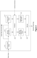
- FIG. 2 illustrates a depth map generator 200 in accordance with some implementations.
- the depth map generator 200 receives mesh data and outputs a blended depth map for an image captured by an image sensor. To that end, the depth map generator 200 further receives camera extrinsics for the image, such as a pose of the image sensor.
- the depth map generator 200 includes a stable mesh buffer 211, a blending mesh buffer 212, and a pending mesh buffer 213. Upon initialization, the stable mesh buffer 211, the blending mesh buffer 212, and the pending mesh buffer 213 are empty.
- the depth map generator 200 includes a renderer 220 which, using the camera extrinsics, reads the stable mesh buffer 211 to generate a stable depth map and write the stable depth map to a stable depth map buffer 231 and reads the blending mesh buffer 212 to generate a blending depth map and write the blending depth map to a blending depth map buffer 232.
- a renderer 220 which, using the camera extrinsics, reads the stable mesh buffer 211 to generate a stable depth map and write the stable depth map to a stable depth map buffer 231 and reads the blending mesh buffer 212 to generate a blending depth map and write the blending depth map to a blending depth map buffer 232.
- the depth map generator 200 includes a blender 240 that reads the stable depth map from the stable depth map buffer 231 and the blending depth map from the blending depth map buffer 232 to generate and output the blended depth map.
- an inverse of the blended depth map is a weighted sum of an inverse of the stable depth map and an inverse of the blending depth map.
- d stable is the depth value for a particular pixel of the stable depth map
- d blended is the depth value for the particular pixel of the blended depth map and ⁇ is a weighting factor.
- the stable mesh buffer 211, the blending mesh buffer 212, and the pending mesh buffer 213 are empty. However, each time mesh data is received by the depth map generator 200, the pending mesh stored in the pending mesh buffer 213 is updated and a timestamp of the pending mesh buffer 213 is updated to a current time.
- updating the pending mesh includes adding the received mesh data to the pending mesh. In various implementations, updating the pending mesh includes overwriting at least a portion of the pending mesh.
- the stable mesh in the stable mesh buffer 211 is overwritten with the blending mesh in the blending mesh buffer 212 and the blending mesh in the blending mesh buffer 212 is overwritten with the pending mesh in the pending mesh buffer 213. Further, the timestamp of the blending mesh buffer 212 is updated to the timestamp of the pending mesh buffer 213.
- the update trigger includes a temporal update trigger detected when an update clock (which is set to zero at initialization and in response to an update trigger) exceeds the blending time period ( T blend ).
- the update trigger includes a motion-based update trigger detected due to motion of the device (e.g., motion of user's head). For example, when a user is moving his or her head, the user is less likely to notice sudden shifts of objects in the displayed image.
- the update trigger includes an eye-based update trigger detected during a blink (or a blink lasting at least a threshold amount of time) or a saccade of the user.
- the update trigger includes a content-based trigger detected based on displayed virtual content. For example, if a virtual explosion is rendered, the user is less likely to notice sudden shifts of objects in the displayed image.
- the blended depth map has a value of infinity for each pixel.
- the stable mesh buffer 211 is overwritten with the blending mesh and the blending mesh buffer 212 is overwritten with a first mesh from the pending mesh buffer 213.
- the stable mesh buffer 211 is empty and the blending mesh buffer 212 stores the first mesh.
- the blended depth map has a value of infinity for each pixel.
- the blended depth map transitions from infinity to first values based on the first mesh.
- the stable mesh buffer 211 is overwritten with the first mesh and the blending mesh buffer 212 is overwritten with a second mesh from the pending mesh buffer 213.
- the stable mesh buffer 211 stores the first mesh and the blending mesh buffer 212 stores the second mesh.
- the blended depth map transitions from the first values to second values based on the second mesh.
- the depth map values transition continuously between initialization and the third time, even at the first time and second time. Accordingly, sudden shifts in the locations of objects in the displayed image are not perceived.
- an update trigger is suppressed in response to determining that the pending mesh in the pending mesh buffer 213 is unstable. For example, if the pending mesh has changed more than a threshold amount during the blending time period, the update trigger may be suppressed for a particular amount of time. In such instances, the weighting factor may be set to 1 during the suppression.
- the pending mesh overwritten into the blending mesh buffer 212 (e.g., the current blending mesh) is unstable after the transition has begun.
- the transition of the weighting factor from 0 to 1 is reversed until the weighting factor is 0 and the blending mesh buffer 212 is overwritten with the current, potentially more stable, pending mesh in the pending mesh buffer 213.
- the depth map generator 200 performs a partial update in which portions of the stable mesh and/or the blending mesh outside a user field-of-view are updated without detecting an update trigger. For example, in various implementations, portions of the stable mesh in the stable mesh buffer 211 not used by the renderer 220 to generate the stable depth map are overwritten by the corresponding portions of the blending mesh in the blending mesh buffer 212. As another example, in various implementations, portions of the stable mesh in the stable mesh buffer 211 and the portions of the blending mesh in the blending mesh buffer 212 not used by the renderer 220 to generate the stable depth map and the blending depth map are overwritten by the corresponding portions of the pending mesh in the pending mesh buffer 213. Similarly, in various implementations, the depth map generator 200 performs a partial update in which portions of the stable mesh and/or the blending mesh occluded by virtual content are updated without detecting an update trigger.
- the timestamp of the blending mesh buffer 212 is updated to the timestamp of the pending mesh buffer 213.
- the timestamp of the blending mesh buffer 212 is unchanged.
- the update clock is reset to zero.
- the update clock is unchanged.
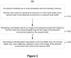
- Figure 3 is a flowchart representation of a method of generating a depth map in accordance with some implementations.
- the method 300 is performed by a device with one or more processors and non-transitory memory (e.g., the electronic device 120 of Figure 1 ).
- the method 300 is performed by processing logic, including hardware, firmware, software, or a combination thereof.
- the method 300 is performed by a processor executing instructions (e.g., code) stored in a non-transitory computer-readable medium (e.g., a memory).
- the method 300 begins, in block 310, with the device storing a first mesh of a physical environment in a first mesh buffer and a second mesh of the physical environment in a second mesh buffer.
- the stable mesh buffer 211 stores a first mesh of the physical environment
- the blending mesh buffer 212 stores a second mesh of the physical environment.
- the method 300 continues, in block 320, with the device rendering a first depth map for an image of the physical environment based on the first mesh and a second depth map for an image of the physical environment based on the second mesh.
- the renderer 220 renders a stable depth map based on the first mesh in the stable mesh buffer 211 and a blending depth map based on the second mesh in the blending mesh buffer 212.
- rendering the first depth map and/or the second depth map is based on camera extrinsics of an image sensor that captured the image of the physical environment, such as a pose of the image sensor at a time the image of the physical environment was captured.
- the method 300 continues, in block 330, with the device generating a blended depth map based on the first depth map, the second depth map, and a difference between a time of the image of the physical environment and a time of the second mesh.
- the blender 240 generates a blended depth map based stored in the stable depth map in the stable depth map buffer 231, the blending depth map stored in the blending depth map buffer 232, and a difference between a time of the image of the physical environment and a timestamp of the blending mesh buffer 212.
- generating the blended depth map includes generating a weighted sum of an inverse of the first depth map and an inverse of the second depth map, wherein a weighting factor of the weighted sum is proportional to the difference between a time of the image of the physical environment and a time of the second mesh.
- the method 300 further includes, in response to detecting an update trigger, overwriting the first mesh buffer with the second mesh and overwriting the second mesh buffer with a third mesh stored in a third mesh buffer.
- the depth map generator 200 in response to an update trigger, overwrites the stable mesh buffer 211 with the mesh in the blending mesh buffer 212 and overwrites the blending mesh buffer 212 with the mesh in the pending mesh buffer 213.
- the update trigger includes a temporal trigger detected when a threshold amount of time has elapsed since initialization or a most recent update trigger.
- the temporal update trigger is detected when an update clock (which is set to zero at initialization and in response to an update trigger) exceeds the blending time period ( T blend ).
- the update trigger includes a motion-based trigger detected based on motion of the device.
- the motion-based update trigger is detected when a velocity of the device exceeds a threshold velocity (in various implementations, for at least a threshold amount of time).
- the update trigger includes an eye-based trigger detected based on an eye characteristic of a user.
- the eye-based trigger is detected when the user blinks (in various implementations, for at least a threshold amount of time) or performs a saccade.
- the update trigger includes a content-based trigger detected based on virtual content displayed by the device.
- the content-based trigger is detected when the virtual content includes a bright flash or substantially occludes the representation of the physical environment.
- the method 300 includes updating the third mesh buffer in response to receiving mesh data.
- the depth map generator 200 in response to receiving mesh data, updates the mesh in the pending mesh buffer 213, which may include adding points and/or vertices and/or overwriting points and/or vertices.
- the method 300 includes, in response to detecting a subsequent update trigger, overwriting the first mesh buffer with the third mesh and overwriting the second mesh buffer with a fourth mesh stored in the third mesh buffer.
- the depth map generator again overwrites the stable mesh buffer 211 with the mesh in the blending mesh buffer 212 (which was once in the pending mesh buffer 213) and overwrites the blending mesh buffer 212 with the mesh in the pending mesh buffer 213 (which is an updated mesh based on received mesh data).
- portions of the first mesh and/or the second mesh outside a user field-of-view are updated without detecting an update trigger.
- the method 300 further includes, in response to determining that a portion of the first mesh was not used in rendering the first depth map, updating the portion of the first mesh with a corresponding portion of the second mesh.
- the method 300 further includes, in response to determining that a portion of the first mesh was not used in rendering the first depth map and a portion of the second mesh was not used in rendering the second depth map, updating the portion of the first mesh and the portion of the second mesh with corresponding portions of a third mesh.
- the blended depth map generated by the method 300 of Figure 3 can be further used in various processes.
- the blended depth map is used to perform perspective correction of an image, transforming the image so as to appear to have been captured from a different location.
- the image is transformed to appear to have been captured from a location of a user's eyes.
- the images are partially transformed such that they appear to have been captured at a location closer to the location of the user's eyes than the location of the scene camera in one or more dimensions of a three-dimensional coordinate system of the device.
- the blended depth map is altered to reduce artifacts.
- the blended depth map is smoothed so as to avoid holes in the transformed image.
- the blended depth map is clamped so as to reduce larger movements of the pixels during the transform.
- the blended depth map is made static such that dynamic objects do not contribute to the depth map.
- the blended depth map is determined using the first mesh of the physical environment and the second mesh of the physical environment without dynamic objects.
- the method 300 further includes, transforming the image of the environment based on the blended depth map and a difference between a first perspective of the image of the environment and a second perspective.
- the blended depth map is used to render shadows or other virtual content over the image of the physical environment.
- the method 300 further includes, generating virtual content based on the blended depth map, compositing the virtual content with the image of the physical environment to generate a display image, and displaying the display image.
- Figure 3 illustrates a method of generating a blended depth map based on a first mesh and a second mesh
- other map representations may be used to generate a blended depth map, such as volumetric maps or keyframes.
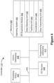
- FIG. 4 is a block diagram of an example of the controller 110 in accordance with some implementations. While certain specific features are illustrated, those skilled in the art will appreciate from the present disclosure that various other features have not been illustrated for the sake of brevity, and so as not to obscure more pertinent aspects of the implementations disclosed herein.
- the controller 110 includes one or more processing units 402 (e.g., microprocessors, application-specific integrated-circuits (ASICs), field-programmable gate arrays (FPGAs), graphics processing units (GPUs), central processing units (CPUs), processing cores, and/or the like), one or more input/output (I/O) devices 406, one or more communication interfaces 408 (e.g., universal serial bus (USB), FIREWIRE, THUNDERBOLT, IEEE 802.3x, IEEE 802.11x, IEEE 802.16x, global system for mobile communications (GSM), code division multiple access (CDMA), time division multiple access (TDMA), global positioning system (GPS), infrared (IR), BLUETOOTH, ZIGBEE, and/or the like type interface), one or more programming (e.g., I/O) interfaces 410, a memory 420, and one or more communication buses 404 for interconnecting these and various other components.
- processing units 402 e.g., microprocessor
- the one or more communication buses 404 include circuitry that interconnects and controls communications between system components.
- the one or more I/O devices 406 include at least one of a keyboard, a mouse, a touchpad, a joystick, one or more microphones, one or more speakers, one or more image sensors, one or more displays, and/or the like.
- the memory 420 includes high-speed random-access memory, such as dynamic random-access memory (DRAM), static random-access memory (SRAM), double-data-rate random-access memory (DDR RAM), or other random-access solid-state memory devices.
- the memory 420 includes non-volatile memory, such as one or more magnetic disk storage devices, optical disk storage devices, flash memory devices, or other non-volatile solid-state storage devices.
- the memory 420 optionally includes one or more storage devices remotely located from the one or more processing units 402.
- the memory 420 comprises a non-transitory computer readable storage medium.
- the memory 420 or the non-transitory computer readable storage medium of the memory 420 stores the following programs, modules and data structures, or a subset thereof including an optional operating system 430 and an XR experience module 440.
- the operating system 430 includes procedures for handling various basic system services and for performing hardware dependent tasks.
- the XR experience module 440 is configured to manage and coordinate one or more XR experiences for one or more users (e.g., a single XR experience for one or more users, or multiple XR experiences for respective groups of one or more users).
- the XR experience module 440 includes a data obtaining unit 442, a tracking unit 444, a coordination unit 446, and a data transmitting unit 448.
- the data obtaining unit 442 is configured to obtain data (e.g., presentation data, interaction data, sensor data, location data, etc.) from at least the electronic device 120 of Figure 1 .
- data e.g., presentation data, interaction data, sensor data, location data, etc.
- the data obtaining unit 442 includes instructions and/or logic therefor, and heuristics and metadata therefor.
- the tracking unit 444 is configured to map the physical environment 105 and to track the position/location of at least the electronic device 120 with respect to the physical environment 105 of Figure 1 .
- the tracking unit 444 includes instructions and/or logic therefor, and heuristics and metadata therefor.
- the coordination unit 446 is configured to manage and coordinate the XR experience presented to the user by the electronic device 120. To that end, in various implementations, the coordination unit 446 includes instructions and/or logic therefor, and heuristics and metadata therefor.
- the data transmitting unit 448 is configured to transmit data (e.g., presentation data, location data, etc.) to at least the electronic device 120.
- data e.g., presentation data, location data, etc.
- the data transmitting unit 448 includes instructions and/or logic therefor, and heuristics and metadata therefor.
- the data obtaining unit 442, the tracking unit 444, the coordination unit 446, and the data transmitting unit 448 are shown as residing on a single device (e.g., the controller 110), it should be understood that in other implementations, any combination of the data obtaining unit 442, the tracking unit 444, the coordination unit 446, and the data transmitting unit 448 may be located in separate computing devices.
- Figure 4 is intended more as functional description of the various features that may be present in a particular implementation as opposed to a structural schematic of the implementations described herein.
- items shown separately could be combined and some items could be separated.
- some functional modules shown separately in Figure 4 could be implemented in a single module and the various functions of single functional blocks could be implemented by one or more functional blocks in various implementations.
- the actual number of modules and the division of particular functions and how features are allocated among them will vary from one implementation to another and, in some implementations, depends in part on the particular combination of hardware, software, and/or firmware chosen for a particular implementation.
- FIG. 5 is a block diagram of an example of the electronic device 120 in accordance with some implementations. While certain specific features are illustrated, those skilled in the art will appreciate from the present disclosure that various other features have not been illustrated for the sake of brevity, and so as not to obscure more pertinent aspects of the implementations disclosed herein.
- the electronic device 120 includes one or more processing units 502 (e.g., microprocessors, ASICs, FPGAs, GPUs, CPUs, processing cores, and/or the like), one or more input/output (I/O) devices and sensors 506, one or more communication interfaces 508 (e.g., USB, FIREWIRE, THUNDERBOLT, IEEE 802.3x, IEEE 802.11x, IEEE 802.16x, GSM, CDMA, TDMA, GPS, IR, BLUETOOTH, ZIGBEE, and/or the like type interface), one or more programming (e.g., I/O) interfaces 510, one or more XR displays 512, one or more optional interior- and/or exterior-facing image sensors 514, a memory 520, and one or more communication buses 504 for interconnecting these and various other components.
- processing units 502 e.g., microprocessors, ASICs, FPGAs, GPUs, CPUs, processing cores, and/or the like
- the one or more communication buses 504 include circuitry that interconnects and controls communications between system components.
- the one or more I/O devices and sensors 506 include at least one of an inertial measurement unit (IMU), an accelerometer, a gyroscope, a thermometer, one or more physiological sensors (e.g., blood pressure monitor, heart rate monitor, blood oxygen sensor, blood glucose sensor, etc.), one or more microphones, one or more speakers, a haptics engine, one or more depth sensors (e.g., a structured light, a time-of-flight, or the like), and/or the like.
- IMU inertial measurement unit
- an accelerometer e.g., an accelerometer
- a gyroscope e.g., a Bosch Sensortec, etc.
- thermometer e.g., a thermometer
- physiological sensors e.g., blood pressure monitor, heart rate monitor, blood oxygen sensor, blood glucose sensor, etc.
- microphones e.g., one or more
- the one or more XR displays 512 are configured to provide the XR experience to the user.
- the one or more XR displays 512 correspond to holographic, digital light processing (DLP), liquid-crystal display (LCD), liquid-crystal on silicon (LCoS), organic light-emitting field-effect transitory (OLET), organic light-emitting diode (OLED), surface-conduction electron-emitter display (SED), fieldemission display (FED), quantum-dot light-emitting diode (QD-LED), micro-electromechanical system (MEMS), and/or the like display types.
- DLP digital light processing
- LCD liquid-crystal display
- LCDoS liquid-crystal on silicon
- OLET organic light-emitting field-effect transitory
- OLET organic light-emitting diode
- SED surface-conduction electron-emitter display
- FED fieldemission display
- QD-LED quantum-dot light-emit
- the one or more XR displays 512 correspond to diffractive, reflective, polarized, holographic, etc. waveguide displays.
- the electronic device 120 includes a single XR display.
- the electronic device includes an XR display for each eye of the user.
- the one or more XR displays 512 are capable of presenting MR and VR content.
- the one or more image sensors 514 are configured to obtain image data that corresponds to at least a portion of the face of the user that includes the eyes of the user (any may be referred to as an eye-tracking camera). In some implementations, the one or more image sensors 514 are configured to be forward-facing so as to obtain image data that corresponds to the physical environment as would be viewed by the user if the electronic device 120 was not present (and may be referred to as a scene camera).
- the one or more optional image sensors 514 can include one or more RGB cameras (e.g., with a complimentary metal-oxide-semiconductor (CMOS) image sensor or a charge-coupled device (CCD) image sensor), one or more infrared (IR) cameras, one or more event-based cameras, and/or the like.
- CMOS complimentary metal-oxide-semiconductor
- CCD charge-coupled device
- IR infrared
- the memory 520 includes high-speed random-access memory, such as DRAM, SRAM, DDR RAM, or other random-access solid-state memory devices.
- the memory 520 includes non-volatile memory, such as one or more magnetic disk storage devices, optical disk storage devices, flash memory devices, or other non-volatile solid-state storage devices.
- the memory 520 optionally includes one or more storage devices remotely located from the one or more processing units 502.
- the memory 520 comprises a non-transitory computer readable storage medium.
- the memory 520 or the non-transitory computer readable storage medium of the memory 520 stores the following programs, modules and data structures, or a subset thereof including an optional operating system 530 and an XR presentation module 540.
- the operating system 530 includes procedures for handling various basic system services and for performing hardware dependent tasks.
- the XR presentation module 540 is configured to present XR content to the user via the one or more XR displays 512.
- the XR presentation module 540 includes a data obtaining unit 542, a depth map generating unit 544, an XR presenting unit 546, and a data transmitting unit 548.
- the data obtaining unit 542 is configured to obtain data (e.g., presentation data, interaction data, sensor data, location data, etc.) from at least the controller 110 of Figure 1 .
- data e.g., presentation data, interaction data, sensor data, location data, etc.
- the data obtaining unit 542 includes instructions and/or logic therefor, and heuristics and metadata therefor.
- the depth map generating unit 544 is configured to generate a depth map by blending a plurality of depth maps corresponding to different times. To that end, in various implementations, the depth map generating unit 544 includes instructions and/or logic therefor, and heuristics and metadata therefor.
- the XR presenting unit 546 is configured to display the transformed image via the one or more XR displays 512.
- the XR presenting unit 546 includes instructions and/or logic therefor, and heuristics and metadata therefor.
- the data transmitting unit 548 is configured to transmit data (e.g., presentation data, location data, etc.) to at least the controller 110. In some implementations, the data transmitting unit 548 is configured to transmit authentication credentials to the electronic device. To that end, in various implementations, the data transmitting unit 548 includes instructions and/or logic therefor, and heuristics and metadata therefor.
- the data obtaining unit 542, the depth map generating unit 544, the XR presenting unit 546, and the data transmitting unit 548 are shown as residing on a single device (e.g., the electronic device 120), it should be understood that in other implementations, any combination of the data obtaining unit 542, the depth map generating unit 544, the XR presenting unit 546, and the data transmitting unit 548 may be located in separate computing devices.
- Figure 5 is intended more as a functional description of the various features that could be present in a particular implementation as opposed to a structural schematic of the implementations described herein.
- items shown separately could be combined and some items could be separated.
- some functional modules shown separately in Figure 5 could be implemented in a single module and the various functions of single functional blocks could be implemented by one or more functional blocks in various implementations.
- the actual number of modules and the division of particular functions and how features are allocated among them will vary from one implementation to another and, in some implementations, depends in part on the particular combination of hardware, software, and/or firmware chosen for a particular implementation.
- first means “first,” “second,” etc.
- these elements should not be limited by these terms. These terms are only used to distinguish one element from another.
- a first node could be termed a second node, and, similarly, a second node could be termed a first node, which changing the meaning of the description, so long as all occurrences of the "first node” are renamed consistently and all occurrences of the "second node” are renamed consistently.
- the first node and the second node are both nodes, but they are not the same node.
- the term “if' may be construed to mean “when” or “upon” or “in response to determining” or “in accordance with a determination” or “in response to detecting,” that a stated condition precedent is true, depending on the context.
- the phrase “if it is determined [that a stated condition precedent is true]” or “if [a stated condition precedent is true]” or “when [a stated condition precedent is true]” may be construed to mean “upon determining” or “in response to determining” or “in accordance with a determination” or “upon detecting” or “in response to detecting” that the stated condition precedent is true, depending on the context.
Landscapes
- Engineering & Computer Science (AREA)
- Theoretical Computer Science (AREA)
- Physics & Mathematics (AREA)
- General Physics & Mathematics (AREA)
- General Engineering & Computer Science (AREA)
- Computer Graphics (AREA)
- Software Systems (AREA)
- Human Computer Interaction (AREA)
- Computer Hardware Design (AREA)
- Geometry (AREA)
- Architecture (AREA)
- Processing Or Creating Images (AREA)
- User Interface Of Digital Computer (AREA)
Abstract
Description
- This application claims priority to
U.S. Provisional Patent App. No. 63/444,094, filed on February 8, 2023 - The present disclosure generally relates to systems, methods, and devices for determining a depth map.
- In various implementations, an extended reality (XR) environment is presented by a head-mounted device (HMD). Various HMDs include a scene camera that captures an image of the physical environment in which the user is present (e.g., a scene) and a display that displays the image to the user. In some instances, this image or portions thereof can be combined with one or more virtual objects to present the user with an XR experience. In other instances, the HMD can operate in a pass-through mode in which the image or portions thereof are presented to the user without the addition of virtual objects. Ideally, the image of the physical environment presented to the user is substantially similar to what the user would see if the HMD were not present. However, due to the different positions of the eyes, the display, and the scene camera in space, this may not occur, resulting in impaired distance perception, disorientation, and poor hand-eye coordination.
- So that the present disclosure can be understood by those of ordinary skill in the art, a more detailed description may be had by reference to aspects of some illustrative implementations, some of which are shown in the accompanying drawings.
-
Figure 1 is a block diagram of an example operating environment in accordance with some implementations. -
Figure 2 is a block diagram of an example depth map generator in accordance with some implementations. -
Figure 3 is a flowchart representation of generating a depth map in accordance with some implementations. -
Figure 4 is a block diagram of an example controller in accordance with some implementations. -
Figure 5 is a block diagram of an example electronic device in accordance with some implementations. - In accordance with common practice the various features illustrated in the drawings may not be drawn to scale. Accordingly, the dimensions of the various features may be arbitrarily expanded or reduced for clarity. In addition, some of the drawings may not depict all of the components of a given system, method or device. Finally, like reference numerals may be used to denote like features throughout the specification and figures.
- Various implementations disclosed herein include devices, systems, and methods for generating a depth map. In various implementations, the method is performed by a device including one or more processors and non-transitory memory. The method includes storing a first mesh of a physical environment in a first mesh buffer and a second mesh of the physical environment in a second mesh buffer. The method includes rendering a first depth map for an image of the physical environment based on the first mesh and a second depth map for the image of the physical environment based on the second mesh. The method includes generating a blended depth map based on the first depth map, the second depth map, and a difference between a time of the image of the physical environment and a time of the second mesh.
- In accordance with some implementations, a device includes one or more processors, a non-transitory memory, and one or more programs; the one or more programs are stored in the non-transitory memory and configured to be executed by the one or more processors. The one or more programs include instructions for performing or causing performance of any of the methods described herein. In accordance with some implementations, a non-transitory computer readable storage medium has stored therein instructions, which, when executed by one or more processors of a device, cause the device to perform or cause performance of any of the methods described herein. In accordance with some implementations, a device includes: one or more processors, a non-transitory memory, and means for performing or causing performance of any of the methods described herein.
- Numerous details are described in order to provide a thorough understanding of the example implementations shown in the drawings. However, the drawings merely show some example aspects of the present disclosure and are therefore not to be considered limiting. Those of ordinary skill in the art will appreciate that other effective aspects and/or variants do not include all of the specific details described herein. Moreover, well-known systems, methods, components, devices, and circuits have not been described in exhaustive detail so as not to obscure more pertinent aspects of the example implementations described herein.
- As described above, in an HMD with a display and a scene camera, the image of the physical environment presented to the user on the display may not always reflect what the user would see if the HMD were not present due to the different positions of the eyes, the display, and the scene camera in space. In various circumstances, this results in poor distance perception, disorientation of the user, and poor hand-eye coordination, e.g., while interacting with the physical environment. Thus, in various implementations, images from the scene camera are transformed such that they appear to have been captured at the location of the user's eyes using a depth map representing, for each pixel of the image, the distance from the scene camera to the object represented by the pixel. However, sudden changes in the depth map may result in disadvantageous sudden shifts of objects (including real objects and/or virtual objects) in the transformed image.
- In various implementations, the depth map is determined based on rendering a mesh of the physical environment. In various implementations, a mesh includes a plurality of points in a three-dimensional coordinate system of the physical environment and vertices between the points. Based on the pose of the scene camera, the mesh can be rendered to form a depth map. When the mesh is suddenly updated (e.g., due to entering a new room of the physical environment or moving furniture in the physical environment), the resulting depth map is suddenly changed resulting in sudden shifts in objects in the transformed image. Accordingly, in various implementations, the depth map resulting from rendering a first mesh obtained at a first time is temporally blended with the depth map resulting from rendering a second mesh obtained at a second, later time.
-
Figure 1 is a block diagram of anexample operating environment 100 in accordance with some implementations. While pertinent features are shown, those of ordinary skill in the art will appreciate from the present disclosure that various other features have not been illustrated for the sake of brevity and so as not to obscure more pertinent aspects of the example implementations disclosed herein. To that end, as a non-limiting example, theoperating environment 100 includes acontroller 110 and anelectronic device 120. - In some implementations, the
controller 110 is configured to manage and coordinate an XR experience for the user. In some implementations, thecontroller 110 includes a suitable combination of software, firmware, and/or hardware. Thecontroller 110 is described in greater detail below with respect toFigure 4 . In some implementations, thecontroller 110 is a computing device that is local or remote relative to thephysical environment 105. For example, thecontroller 110 is a local server located within thephysical environment 105. In another example, thecontroller 110 is a remote server located outside of the physical environment 105 (e.g., a cloud server, central server, etc.). In some implementations, thecontroller 110 is communicatively coupled with theelectronic device 120 via one or more wired or wireless communication channels 144 (e.g., BLUETOOTH, IEEE 802.11x, IEEE 802.16x, IEEE 802.3x, etc.). In another example, thecontroller 110 is included within the enclosure of theelectronic device 120. In some implementations, the functionalities of thecontroller 110 are provided by and/or combined with theelectronic device 120. - In some implementations, the
electronic device 120 is configured to provide the XR experience to the user. In some implementations, theelectronic device 120 includes a suitable combination of software, firmware, and/or hardware. According to some implementations, theelectronic device 120 presents, via adisplay 122, XR content to the user while the user is physically present within thephysical environment 105 that includes a table 107 within the field-of-view 111 of theelectronic device 120. As such, in some implementations, the user holds theelectronic device 120 in his/her hand(s). In some implementations, while providing XR content, theelectronic device 120 is configured to display an XR object (e.g., an XR cylinder 109) and to enable video pass-through of the physical environment 105 (e.g., including arepresentation 117 of the table 107) on adisplay 122. Theelectronic device 120 is described in greater detail below with respect toFigure 5 . - According to some implementations, the
electronic device 120 provides an XR experience to the user while the user is virtually and/or physically present within thephysical environment 105. - In some implementations, the user wears the
electronic device 120 on his/her head. For example, in some implementations, the electronic device includes a head-mounted system (HMS), head-mounted device (HMD), or head-mounted enclosure (HME). As such, theelectronic device 120 includes one or more XR displays provided to display the XR content. For example, in various implementations, theelectronic device 120 encloses the field-of view of the user. In some implementations, theelectronic device 120 is a handheld device (such as a smartphone or tablet) configured to present XR content, and rather than wearing theelectronic device 120, the user holds the device with a display directed towards the field-of view of the user and a camera directed towards thephysical environment 105. In some implementations, the handheld device can be placed within an enclosure that can be worn on the head of the user. In some implementations, theelectronic device 120 is replaced with an XR chamber, enclosure, or room configured to present XR content in which the user does not wear or hold theelectronic device 120. -
Figure 2 illustrates adepth map generator 200 in accordance with some implementations. Thedepth map generator 200 receives mesh data and outputs a blended depth map for an image captured by an image sensor. To that end, thedepth map generator 200 further receives camera extrinsics for the image, such as a pose of the image sensor. - The
depth map generator 200 includes astable mesh buffer 211, ablending mesh buffer 212, and a pendingmesh buffer 213. Upon initialization, thestable mesh buffer 211, theblending mesh buffer 212, and the pendingmesh buffer 213 are empty. - The
depth map generator 200 includes arenderer 220 which, using the camera extrinsics, reads thestable mesh buffer 211 to generate a stable depth map and write the stable depth map to a stabledepth map buffer 231 and reads theblending mesh buffer 212 to generate a blending depth map and write the blending depth map to a blendingdepth map buffer 232. Upon initialization, because thestable mesh buffer 211 and theblending mesh buffer 212 are empty, the stable depth map and the blending depth map have the value of infinity for each pixel of the image. - The
depth map generator 200 includes ablender 240 that reads the stable depth map from the stabledepth map buffer 231 and the blending depth map from the blendingdepth map buffer 232 to generate and output the blended depth map. In various implementations, an inverse of the blended depth map is a weighted sum of an inverse of the stable depth map and an inverse of the blending depth map. For example, where dstable is the depth value for a particular pixel of the stable depth map, dblending is the depth value for the particular pixel of the blending depth map:
- In various implementations, the weighting factor is a function of a difference between a timestamp of the image and a timestamp of the
blending mesh buffer 212. In various implementations, the weighting factor is a function of a blending time period. In various implementations, the blending time period is 1 second, 2 seconds, 5 seconds, 10 seconds, 20 seconds, 30 seconds, 1 minute, or any time period. For example, in various implementations, where timage is a timestamp of the image, trending is a timestamp of theblending mesh buffer 212, and Tblend is a blending time period:
- As noted above, upon initialization, the
stable mesh buffer 211, theblending mesh buffer 212, and the pendingmesh buffer 213 are empty. However, each time mesh data is received by thedepth map generator 200, the pending mesh stored in the pendingmesh buffer 213 is updated and a timestamp of the pendingmesh buffer 213 is updated to a current time. In various implementations, updating the pending mesh includes adding the received mesh data to the pending mesh. In various implementations, updating the pending mesh includes overwriting at least a portion of the pending mesh. - In various implementations, in response to detecting an update trigger, the stable mesh in the
stable mesh buffer 211 is overwritten with the blending mesh in theblending mesh buffer 212 and the blending mesh in theblending mesh buffer 212 is overwritten with the pending mesh in the pendingmesh buffer 213. Further, the timestamp of theblending mesh buffer 212 is updated to the timestamp of the pendingmesh buffer 213. - In various implementations, the update trigger includes a temporal update trigger detected when an update clock (which is set to zero at initialization and in response to an update trigger) exceeds the blending time period (Tblend ). In various implementations, the update trigger includes a motion-based update trigger detected due to motion of the device (e.g., motion of user's head). For example, when a user is moving his or her head, the user is less likely to notice sudden shifts of objects in the displayed image. In various implementations, the update trigger includes an eye-based update trigger detected during a blink (or a blink lasting at least a threshold amount of time) or a saccade of the user. In various implementations, the update trigger includes a content-based trigger detected based on displayed virtual content. For example, if a virtual explosion is rendered, the user is less likely to notice sudden shifts of objects in the displayed image.
- As an example in which only temporal update triggers are detected, the
stable mesh buffer 211 and theblending mesh buffer 212 are empty between an initialization time (T0 ) and a first time equal to a blending time period after the initialization time (T1 =T0 +Tblend ). At the first time, the blended depth map has a value of infinity for each pixel. At the first time, thestable mesh buffer 211 is overwritten with the blending mesh and theblending mesh buffer 212 is overwritten with a first mesh from the pendingmesh buffer 213. Thus, at the first time, thestable mesh buffer 211 is empty and theblending mesh buffer 212 stores the first mesh. At the first time, the blended depth map has a value of infinity for each pixel. Between the first time and a second time equal to a blending time period after the first time (T2 =T1 +Tblend ), the blended depth map transitions from infinity to first values based on the first mesh. At the second time, thestable mesh buffer 211 is overwritten with the first mesh and theblending mesh buffer 212 is overwritten with a second mesh from the pendingmesh buffer 213. Thus, at the first time, thestable mesh buffer 211 stores the first mesh and theblending mesh buffer 212 stores the second mesh. Between the second time and a third time equal to a blending time period after the first time (T3 =T2 +Tblend ), the blended depth map transitions from the first values to second values based on the second mesh. The depth map values transition continuously between initialization and the third time, even at the first time and second time. Accordingly, sudden shifts in the locations of objects in the displayed image are not perceived. - In various implementations, an update trigger is suppressed in response to determining that the pending mesh in the pending
mesh buffer 213 is unstable. For example, if the pending mesh has changed more than a threshold amount during the blending time period, the update trigger may be suppressed for a particular amount of time. In such instances, the weighting factor may be set to 1 during the suppression. - In various implementations, it may be determined that the pending mesh overwritten into the blending mesh buffer 212 (e.g., the current blending mesh) is unstable after the transition has begun. In various implementations, the transition of the weighting factor from 0 to 1 is reversed until the weighting factor is 0 and the
blending mesh buffer 212 is overwritten with the current, potentially more stable, pending mesh in the pendingmesh buffer 213. - In various implementations, the
depth map generator 200 performs a partial update in which portions of the stable mesh and/or the blending mesh outside a user field-of-view are updated without detecting an update trigger. For example, in various implementations, portions of the stable mesh in thestable mesh buffer 211 not used by therenderer 220 to generate the stable depth map are overwritten by the corresponding portions of the blending mesh in theblending mesh buffer 212. As another example, in various implementations, portions of the stable mesh in thestable mesh buffer 211 and the portions of the blending mesh in theblending mesh buffer 212 not used by therenderer 220 to generate the stable depth map and the blending depth map are overwritten by the corresponding portions of the pending mesh in the pendingmesh buffer 213. Similarly, in various implementations, thedepth map generator 200 performs a partial update in which portions of the stable mesh and/or the blending mesh occluded by virtual content are updated without detecting an update trigger. - In various implementations, in response to such a partial update, the timestamp of the
blending mesh buffer 212 is updated to the timestamp of the pendingmesh buffer 213. In various implementations, in response to such a partial update, the timestamp of theblending mesh buffer 212 is unchanged. In various implementations, in response to such a partial update the update clock is reset to zero. In various implementations, in response to such a partial update, the update clock is unchanged. -
Figure 3 is a flowchart representation of a method of generating a depth map in accordance with some implementations. In various implementations, themethod 300 is performed by a device with one or more processors and non-transitory memory (e.g., theelectronic device 120 ofFigure 1 ). In some implementations, themethod 300 is performed by processing logic, including hardware, firmware, software, or a combination thereof. In some implementations, themethod 300 is performed by a processor executing instructions (e.g., code) stored in a non-transitory computer-readable medium (e.g., a memory). - The
method 300 begins, inblock 310, with the device storing a first mesh of a physical environment in a first mesh buffer and a second mesh of the physical environment in a second mesh buffer. For example, inFigure 2 , thestable mesh buffer 211 stores a first mesh of the physical environment and theblending mesh buffer 212 stores a second mesh of the physical environment. - The
method 300 continues, inblock 320, with the device rendering a first depth map for an image of the physical environment based on the first mesh and a second depth map for an image of the physical environment based on the second mesh. For example, inFigure 2 , therenderer 220 renders a stable depth map based on the first mesh in thestable mesh buffer 211 and a blending depth map based on the second mesh in theblending mesh buffer 212. In various implementations, rendering the first depth map and/or the second depth map is based on camera extrinsics of an image sensor that captured the image of the physical environment, such as a pose of the image sensor at a time the image of the physical environment was captured. - The
method 300 continues, inblock 330, with the device generating a blended depth map based on the first depth map, the second depth map, and a difference between a time of the image of the physical environment and a time of the second mesh. For example, inFigure 2 , theblender 240 generates a blended depth map based stored in the stable depth map in the stabledepth map buffer 231, the blending depth map stored in the blendingdepth map buffer 232, and a difference between a time of the image of the physical environment and a timestamp of theblending mesh buffer 212. - In various implementations, generating the blended depth map includes generating a weighted sum of an inverse of the first depth map and an inverse of the second depth map, wherein a weighting factor of the weighted sum is proportional to the difference between a time of the image of the physical environment and a time of the second mesh.
- In various implementations, the
method 300 further includes, in response to detecting an update trigger, overwriting the first mesh buffer with the second mesh and overwriting the second mesh buffer with a third mesh stored in a third mesh buffer. For example, inFigure 2 , in response to an update trigger, thedepth map generator 200 overwrites thestable mesh buffer 211 with the mesh in theblending mesh buffer 212 and overwrites theblending mesh buffer 212 with the mesh in the pendingmesh buffer 213. - In various implementations, the update trigger includes a temporal trigger detected when a threshold amount of time has elapsed since initialization or a most recent update trigger. For example, in various implementations, the temporal update trigger is detected when an update clock (which is set to zero at initialization and in response to an update trigger) exceeds the blending time period (Tblend ). In various implementations, the update trigger includes a motion-based trigger detected based on motion of the device. For example, in various implementations, the motion-based update trigger is detected when a velocity of the device exceeds a threshold velocity (in various implementations, for at least a threshold amount of time). In various implementations, the update trigger includes an eye-based trigger detected based on an eye characteristic of a user. For example, in various implementations, the eye-based trigger is detected when the user blinks (in various implementations, for at least a threshold amount of time) or performs a saccade. In various implementations, the update trigger includes a content-based trigger detected based on virtual content displayed by the device. For example, in various implementations, the content-based trigger is detected when the virtual content includes a bright flash or substantially occludes the representation of the physical environment.
- In various implementations, the
method 300 includes updating the third mesh buffer in response to receiving mesh data. For example, inFigure 2 , in response to receiving mesh data, thedepth map generator 200 updates the mesh in the pendingmesh buffer 213, which may include adding points and/or vertices and/or overwriting points and/or vertices. - In various implementations, the
method 300 includes, in response to detecting a subsequent update trigger, overwriting the first mesh buffer with the third mesh and overwriting the second mesh buffer with a fourth mesh stored in the third mesh buffer. For example, inFigure 2 , after overwriting thestable mesh buffer 211 with the mesh in theblending mesh buffer 212 and overwriting theblending mesh buffer 212 with the mesh in the pendingmesh buffer 213, in response to detecting another update trigger, the depth map generator, again overwrites thestable mesh buffer 211 with the mesh in the blending mesh buffer 212 (which was once in the pending mesh buffer 213) and overwrites theblending mesh buffer 212 with the mesh in the pending mesh buffer 213 (which is an updated mesh based on received mesh data). - In various implementations, portions of the first mesh and/or the second mesh outside a user field-of-view are updated without detecting an update trigger. In various implementations, the
method 300 further includes, in response to determining that a portion of the first mesh was not used in rendering the first depth map, updating the portion of the first mesh with a corresponding portion of the second mesh. In various implementations, themethod 300 further includes, in response to determining that a portion of the first mesh was not used in rendering the first depth map and a portion of the second mesh was not used in rendering the second depth map, updating the portion of the first mesh and the portion of the second mesh with corresponding portions of a third mesh. - The blended depth map generated by the
method 300 ofFigure 3 can be further used in various processes. For example, in various implementations, the blended depth map is used to perform perspective correction of an image, transforming the image so as to appear to have been captured from a different location. In various implementations, the image is transformed to appear to have been captured from a location of a user's eyes. In various implementations, rather than transforming the images such that they appear to have been captured at the location of the user's eyes, the images are partially transformed such that they appear to have been captured at a location closer to the location of the user's eyes than the location of the scene camera in one or more dimensions of a three-dimensional coordinate system of the device. - In various implementations, the blended depth map is altered to reduce artifacts. For example, in various implementations, the blended depth map is smoothed so as to avoid holes in the transformed image. As another example, in various implementations, the blended depth map is clamped so as to reduce larger movements of the pixels during the transform. In various implementations, the blended depth map is made static such that dynamic objects do not contribute to the depth map. For example, in various implementations, the blended depth map is determined using the first mesh of the physical environment and the second mesh of the physical environment without dynamic objects.
- Thus, in various implementations, the
method 300 further includes, transforming the image of the environment based on the blended depth map and a difference between a first perspective of the image of the environment and a second perspective. - In various implementations, the blended depth map is used to render shadows or other virtual content over the image of the physical environment. Thus, in various implementations, the
method 300 further includes, generating virtual content based on the blended depth map, compositing the virtual content with the image of the physical environment to generate a display image, and displaying the display image. - Whereas
Figure 3 illustrates a method of generating a blended depth map based on a first mesh and a second mesh, in various implementations other map representations may be used to generate a blended depth map, such as volumetric maps or keyframes. -
Figure 4 is a block diagram of an example of thecontroller 110 in accordance with some implementations. While certain specific features are illustrated, those skilled in the art will appreciate from the present disclosure that various other features have not been illustrated for the sake of brevity, and so as not to obscure more pertinent aspects of the implementations disclosed herein. To that end, as a non-limiting example, in some implementations thecontroller 110 includes one or more processing units 402 (e.g., microprocessors, application-specific integrated-circuits (ASICs), field-programmable gate arrays (FPGAs), graphics processing units (GPUs), central processing units (CPUs), processing cores, and/or the like), one or more input/output (I/O)devices 406, one or more communication interfaces 408 (e.g., universal serial bus (USB), FIREWIRE, THUNDERBOLT, IEEE 802.3x, IEEE 802.11x, IEEE 802.16x, global system for mobile communications (GSM), code division multiple access (CDMA), time division multiple access (TDMA), global positioning system (GPS), infrared (IR), BLUETOOTH, ZIGBEE, and/or the like type interface), one or more programming (e.g., I/O) interfaces 410, amemory 420, and one ormore communication buses 404 for interconnecting these and various other components. - In some implementations, the one or
more communication buses 404 include circuitry that interconnects and controls communications between system components. In some implementations, the one or more I/O devices 406 include at least one of a keyboard, a mouse, a touchpad, a joystick, one or more microphones, one or more speakers, one or more image sensors, one or more displays, and/or the like. - The
memory 420 includes high-speed random-access memory, such as dynamic random-access memory (DRAM), static random-access memory (SRAM), double-data-rate random-access memory (DDR RAM), or other random-access solid-state memory devices. In some implementations, thememory 420 includes non-volatile memory, such as one or more magnetic disk storage devices, optical disk storage devices, flash memory devices, or other non-volatile solid-state storage devices. Thememory 420 optionally includes one or more storage devices remotely located from the one ormore processing units 402. Thememory 420 comprises a non-transitory computer readable storage medium. In some implementations, thememory 420 or the non-transitory computer readable storage medium of thememory 420 stores the following programs, modules and data structures, or a subset thereof including anoptional operating system 430 and anXR experience module 440. - The
operating system 430 includes procedures for handling various basic system services and for performing hardware dependent tasks. In some implementations, theXR experience module 440 is configured to manage and coordinate one or more XR experiences for one or more users (e.g., a single XR experience for one or more users, or multiple XR experiences for respective groups of one or more users). To that end, in various implementations, theXR experience module 440 includes adata obtaining unit 442, atracking unit 444, acoordination unit 446, and adata transmitting unit 448. - In some implementations, the
data obtaining unit 442 is configured to obtain data (e.g., presentation data, interaction data, sensor data, location data, etc.) from at least theelectronic device 120 ofFigure 1 . To that end, in various implementations, thedata obtaining unit 442 includes instructions and/or logic therefor, and heuristics and metadata therefor. - In some implementations, the
tracking unit 444 is configured to map thephysical environment 105 and to track the position/location of at least theelectronic device 120 with respect to thephysical environment 105 ofFigure 1 . To that end, in various implementations, thetracking unit 444 includes instructions and/or logic therefor, and heuristics and metadata therefor. - In some implementations, the
coordination unit 446 is configured to manage and coordinate the XR experience presented to the user by theelectronic device 120. To that end, in various implementations, thecoordination unit 446 includes instructions and/or logic therefor, and heuristics and metadata therefor. - In some implementations, the
data transmitting unit 448 is configured to transmit data (e.g., presentation data, location data, etc.) to at least theelectronic device 120. To that end, in various implementations, thedata transmitting unit 448 includes instructions and/or logic therefor, and heuristics and metadata therefor. - Although the
data obtaining unit 442, thetracking unit 444, thecoordination unit 446, and thedata transmitting unit 448 are shown as residing on a single device (e.g., the controller 110), it should be understood that in other implementations, any combination of thedata obtaining unit 442, thetracking unit 444, thecoordination unit 446, and thedata transmitting unit 448 may be located in separate computing devices. - Moreover,
Figure 4 is intended more as functional description of the various features that may be present in a particular implementation as opposed to a structural schematic of the implementations described herein. As recognized by those of ordinary skill in the art, items shown separately could be combined and some items could be separated. For example, some functional modules shown separately inFigure 4 could be implemented in a single module and the various functions of single functional blocks could be implemented by one or more functional blocks in various implementations. The actual number of modules and the division of particular functions and how features are allocated among them will vary from one implementation to another and, in some implementations, depends in part on the particular combination of hardware, software, and/or firmware chosen for a particular implementation. -
Figure 5 is a block diagram of an example of theelectronic device 120 in accordance with some implementations. While certain specific features are illustrated, those skilled in the art will appreciate from the present disclosure that various other features have not been illustrated for the sake of brevity, and so as not to obscure more pertinent aspects of the implementations disclosed herein. To that end, as a non-limiting example, in some implementations theelectronic device 120 includes one or more processing units 502 (e.g., microprocessors, ASICs, FPGAs, GPUs, CPUs, processing cores, and/or the like), one or more input/output (I/O) devices andsensors 506, one or more communication interfaces 508 (e.g., USB, FIREWIRE, THUNDERBOLT, IEEE 802.3x, IEEE 802.11x, IEEE 802.16x, GSM, CDMA, TDMA, GPS, IR, BLUETOOTH, ZIGBEE, and/or the like type interface), one or more programming (e.g., I/O) interfaces 510, one or more XR displays 512, one or more optional interior- and/or exterior-facingimage sensors 514, amemory 520, and one or more communication buses 504 for interconnecting these and various other components. - In some implementations, the one or more communication buses 504 include circuitry that interconnects and controls communications between system components. In some implementations, the one or more I/O devices and
sensors 506 include at least one of an inertial measurement unit (IMU), an accelerometer, a gyroscope, a thermometer, one or more physiological sensors (e.g., blood pressure monitor, heart rate monitor, blood oxygen sensor, blood glucose sensor, etc.), one or more microphones, one or more speakers, a haptics engine, one or more depth sensors (e.g., a structured light, a time-of-flight, or the like), and/or the like. - In some implementations, the one or more XR displays 512 are configured to provide the XR experience to the user. In some implementations, the one or more XR displays 512 correspond to holographic, digital light processing (DLP), liquid-crystal display (LCD), liquid-crystal on silicon (LCoS), organic light-emitting field-effect transitory (OLET), organic light-emitting diode (OLED), surface-conduction electron-emitter display (SED), fieldemission display (FED), quantum-dot light-emitting diode (QD-LED), micro-electromechanical system (MEMS), and/or the like display types. In some implementations, the one or more XR displays 512 correspond to diffractive, reflective, polarized, holographic, etc. waveguide displays. For example, the
electronic device 120 includes a single XR display. In another example, the electronic device includes an XR display for each eye of the user. In some implementations, the one or more XR displays 512 are capable of presenting MR and VR content. - In some implementations, the one or
more image sensors 514 are configured to obtain image data that corresponds to at least a portion of the face of the user that includes the eyes of the user (any may be referred to as an eye-tracking camera). In some implementations, the one ormore image sensors 514 are configured to be forward-facing so as to obtain image data that corresponds to the physical environment as would be viewed by the user if theelectronic device 120 was not present (and may be referred to as a scene camera). The one or moreoptional image sensors 514 can include one or more RGB cameras (e.g., with a complimentary metal-oxide-semiconductor (CMOS) image sensor or a charge-coupled device (CCD) image sensor), one or more infrared (IR) cameras, one or more event-based cameras, and/or the like. - The
memory 520 includes high-speed random-access memory, such as DRAM, SRAM, DDR RAM, or other random-access solid-state memory devices. In some implementations, thememory 520 includes non-volatile memory, such as one or more magnetic disk storage devices, optical disk storage devices, flash memory devices, or other non-volatile solid-state storage devices. Thememory 520 optionally includes one or more storage devices remotely located from the one ormore processing units 502. Thememory 520 comprises a non-transitory computer readable storage medium. In some implementations, thememory 520 or the non-transitory computer readable storage medium of thememory 520 stores the following programs, modules and data structures, or a subset thereof including anoptional operating system 530 and anXR presentation module 540. - The
operating system 530 includes procedures for handling various basic system services and for performing hardware dependent tasks. In some implementations, theXR presentation module 540 is configured to present XR content to the user via the one or more XR displays 512. To that end, in various implementations, theXR presentation module 540 includes adata obtaining unit 542, a depthmap generating unit 544, anXR presenting unit 546, and adata transmitting unit 548. - In some implementations, the
data obtaining unit 542 is configured to obtain data (e.g., presentation data, interaction data, sensor data, location data, etc.) from at least thecontroller 110 ofFigure 1 . To that end, in various implementations, thedata obtaining unit 542 includes instructions and/or logic therefor, and heuristics and metadata therefor. - In some implementations, the depth
map generating unit 544 is configured to generate a depth map by blending a plurality of depth maps corresponding to different times. To that end, in various implementations, the depthmap generating unit 544 includes instructions and/or logic therefor, and heuristics and metadata therefor. - In some implementations, the
XR presenting unit 546 is configured to display the transformed image via the one or more XR displays 512. To that end, in various implementations, theXR presenting unit 546 includes instructions and/or logic therefor, and heuristics and metadata therefor. - In some implementations, the
data transmitting unit 548 is configured to transmit data (e.g., presentation data, location data, etc.) to at least thecontroller 110. In some implementations, thedata transmitting unit 548 is configured to transmit authentication credentials to the electronic device. To that end, in various implementations, thedata transmitting unit 548 includes instructions and/or logic therefor, and heuristics and metadata therefor. - Although the
data obtaining unit 542, the depthmap generating unit 544, theXR presenting unit 546, and thedata transmitting unit 548 are shown as residing on a single device (e.g., the electronic device 120), it should be understood that in other implementations, any combination of thedata obtaining unit 542, the depthmap generating unit 544, theXR presenting unit 546, and thedata transmitting unit 548 may be located in separate computing devices. - Moreover,
Figure 5 is intended more as a functional description of the various features that could be present in a particular implementation as opposed to a structural schematic of the implementations described herein. As recognized by those of ordinary skill in the art, items shown separately could be combined and some items could be separated. For example, some functional modules shown separately inFigure 5 could be implemented in a single module and the various functions of single functional blocks could be implemented by one or more functional blocks in various implementations. The actual number of modules and the division of particular functions and how features are allocated among them will vary from one implementation to another and, in some implementations, depends in part on the particular combination of hardware, software, and/or firmware chosen for a particular implementation. - While various aspects of implementations within the scope of the appended claims are described above, it should be apparent that the various features of implementations described above may be embodied in a wide variety of forms and that any specific structure and/or function described above is merely illustrative. Based on the present disclosure one skilled in the art should appreciate that an aspect described herein may be implemented independently of any other aspects and that two or more of these aspects may be combined in various ways. For example, an apparatus may be implemented and/or a method may be practiced using any number of the aspects set forth herein. In addition, such an apparatus may be implemented and/or such a method may be practiced using other structure and/or functionality in addition to or other than one or more of the aspects set forth herein.
- It will also be understood that, although the terms "first," "second," etc. may be used herein to describe various elements, these elements should not be limited by these terms. These terms are only used to distinguish one element from another. For example, a first node could be termed a second node, and, similarly, a second node could be termed a first node, which changing the meaning of the description, so long as all occurrences of the "first node" are renamed consistently and all occurrences of the "second node" are renamed consistently. The first node and the second node are both nodes, but they are not the same node.
- The terminology used herein is for the purpose of describing particular implementations only and is not intended to be limiting of the claims. As used in the description of the implementations and the appended claims, the singular forms "a," "an," and "the" are intended to include the plural forms as well, unless the context clearly indicates otherwise. It will also be understood that the term "and/or" as used herein refers to and encompasses any and all possible combinations of one or more of the associated listed items. It will be further understood that the terms "comprises" and/or "comprising," when used in this specification, specify the presence of stated features, integers, steps, operations, elements, and/or components, but do not preclude the presence or addition of one or more other features, integers, steps, operations, elements, components, and/or groups thereof.
- As used herein, the term "if' may be construed to mean "when" or "upon" or "in response to determining" or "in accordance with a determination" or "in response to detecting," that a stated condition precedent is true, depending on the context. Similarly, the phrase "if it is determined [that a stated condition precedent is true]" or "if [a stated condition precedent is true]" or "when [a stated condition precedent is true]" may be construed to mean "upon determining" or "in response to determining" or "in accordance with a determination" or "upon detecting" or "in response to detecting" that the stated condition precedent is true, depending on the context.
Claims (15)
- A method comprising:
at a device including one or more processors and non-transitory memory:storing a first mesh of a physical environment in a first mesh buffer and a second mesh of the physical environment in a second mesh buffer;rendering a first depth map for an image of the physical environment based on the first mesh and a second depth map for the image of the physical environment based on the second mesh; andgenerating a blended depth map based on the first depth map, the second depth map, and a difference between a time of the image of the physical environment and a time of the second mesh. - The method of claim 1, wherein generating the blended depth map includes generating a weighted sum of an inverse of the first depth map and an inverse of the second depth map, wherein a weighting factor of the weighted sum is proportional to the difference between a time of the image of the physical environment and a time of the second mesh.
- The method of claim 1 or 2, further comprising, in response to detecting an update trigger, overwriting the first mesh buffer with the second mesh and overwriting the second mesh buffer with a third mesh stored in a third mesh buffer.
- The method of claim 3, wherein the update trigger includes a temporal trigger detected when a threshold amount of time has elapsed since an initialization or a most recent update trigger.
- The method of claim 3 or 4, wherein the update trigger includes a motion-based trigger detected based on motion of the device.
- The method of any of claims 3-5, wherein the update trigger includes an eye-based trigger detected based on an eye characteristic of a user.
- The method of any of claims 3-6, wherein the update trigger includes a content-based trigger detected based on virtual content displayed by the device.
- The method of any of claims 3-7, further comprising, in response to determining that the third mesh is unstable, suppressing the update trigger for a particular amount of time.
- The method of any of claims 3-8, further comprising updating the third mesh buffer in response to receiving mesh data.
- The method of any of claims 3-9, further comprising, in response to detecting a subsequent update trigger, overwriting the first mesh buffer with the third mesh and overwriting the second mesh buffer with a fourth mesh stored in the third mesh buffer.
- The method of any of claims 1-10, further comprising, in response to determining that a portion of the first mesh was not used in rendering the first depth map, updating the portion of the first mesh with a corresponding portion of the second mesh.
- The method of any of claims 1-11, further comprising, in response to determining that a portion of the first mesh was not used in rendering the first depth map and a portion of the second mesh was not used in rendering the second depth map, updating the portion of the first mesh and the portion of the second mesh with corresponding portions of a third mesh.
- The method of any of claims 1-12, further comprising transforming the image of the environment based on the blended depth map and a difference between a first perspective of the image of the environment and a second perspective.
- A device comprising:a non-transitory memory; andone or more processors to:obtain a first mesh of a physical environment and a second mesh of the physical environment;render a first depth map for an image of the physical environment based on the first mesh and a second depth map for the image of the physical environment based on the second mesh; andgenerate a blended depth map based on the first depth map, the second depth map, and a difference between a time of the image of the physical environment and a time of the second mesh.
- A non-transitory memory storing one or more programs, which, when executed by one or more processors of a device, cause the device to perform any of the methods of claims 1-13.
Applications Claiming Priority (1)
| Application Number | Priority Date | Filing Date | Title |
|---|---|---|---|
| US202363444094P | 2023-02-08 | 2023-02-08 |
Publications (2)
| Publication Number | Publication Date |
|---|---|
| EP4414814A1 true EP4414814A1 (en) | 2024-08-14 |
| EP4414814B1 EP4414814B1 (en) | 2025-08-06 |
Family
ID=89854608
Family Applications (1)
| Application Number | Title | Priority Date | Filing Date |
|---|---|---|---|
| EP24156305.5A Active EP4414814B1 (en) | 2023-02-08 | 2024-02-07 | Temporal blending of depth maps |
Country Status (3)
| Country | Link |
|---|---|
| US (1) | US20240265636A1 (en) |
| EP (1) | EP4414814B1 (en) |
| CN (1) | CN118470257A (en) |
Citations (2)
| Publication number | Priority date | Publication date | Assignee | Title |
|---|---|---|---|---|
| US20170272724A1 (en) * | 2016-03-17 | 2017-09-21 | Electronics And Telecommunications Research Institute | Apparatus and method for multi-view stereo |
| US20210358084A1 (en) * | 2020-05-13 | 2021-11-18 | Microsoft Technology Licensing, Llc | Upsampling low temporal resolution depth maps |
Family Cites Families (3)
| Publication number | Priority date | Publication date | Assignee | Title |
|---|---|---|---|---|
| JP3524529B2 (en) * | 2000-12-19 | 2004-05-10 | 株式会社ソニー・コンピュータエンタテインメント | Drawing processing program to be executed by computer, recording medium storing drawing processing program to be executed by computer, program execution device, drawing device and method |
| JP2018514968A (en) * | 2015-03-01 | 2018-06-07 | ネクストブイアール・インコーポレイテッド | Method and apparatus for making environmental measurements and / or using such measurements in 3D image rendering |
| KR102581134B1 (en) * | 2016-12-06 | 2023-09-21 | 코닌클리케 필립스 엔.브이. | Apparatus and method for generating light intensity images |
-
2024
- 2024-02-07 EP EP24156305.5A patent/EP4414814B1/en active Active
- 2024-02-08 CN CN202410177242.1A patent/CN118470257A/en active Pending
- 2024-02-08 US US18/436,616 patent/US20240265636A1/en active Pending
Patent Citations (2)
| Publication number | Priority date | Publication date | Assignee | Title |
|---|---|---|---|---|
| US20170272724A1 (en) * | 2016-03-17 | 2017-09-21 | Electronics And Telecommunications Research Institute | Apparatus and method for multi-view stereo |
| US20210358084A1 (en) * | 2020-05-13 | 2021-11-18 | Microsoft Technology Licensing, Llc | Upsampling low temporal resolution depth maps |
Also Published As
| Publication number | Publication date |
|---|---|
| CN118470257A (en) | 2024-08-09 |
| US20240265636A1 (en) | 2024-08-08 |
| EP4414814B1 (en) | 2025-08-06 |
Similar Documents
| Publication | Publication Date | Title |
|---|---|---|
| US12423841B2 (en) | Scene camera retargeting | |
| US11867917B2 (en) | Small field of view display mitigation using virtual object display characteristics | |
| US20240233220A1 (en) | Foveated Anti-Aliasing | |
| US11276143B2 (en) | Error concealment for a head-mountable device | |
| US20240112303A1 (en) | Context-Based Selection of Perspective Correction Operations | |
| US20240098232A1 (en) | Partial Perspective Correction with Mitigation of Vertical Disparity | |
| US12586151B2 (en) | Frame rate extrapolation | |
| US20240233205A1 (en) | Perspective Correction With Depth Clamping | |
| EP4414814A1 (en) | Temporal blending of depth maps | |
| US20240098243A1 (en) | Predictive Perspective Correction | |
| US20240070931A1 (en) | Distributed Content Rendering | |
| US20250124670A1 (en) | Dynamic Portals | |
| US11715220B1 (en) | Method and device for depth sensor power savings | |
| US11836872B1 (en) | Method and device for masked late-stage shift | |
| US20240078692A1 (en) | Temporally Stable Perspective Correction | |
| US11838486B1 (en) | Method and device for perspective correction using one or more keyframes | |
| US20240005536A1 (en) | Perspective Correction of User Input Objects | |
| US12316819B1 (en) | Method and device for perspective correction using a smooth depth map | |
| US20240078640A1 (en) | Perspective Correction with Gravitational Smoothing | |
| US12223117B1 (en) | Spatiotemporal smoothing for improved hand tracking |
Legal Events
| Date | Code | Title | Description |
|---|---|---|---|
| PUAI | Public reference made under article 153(3) epc to a published international application that has entered the european phase |
Free format text: ORIGINAL CODE: 0009012 |
|
| STAA | Information on the status of an ep patent application or granted ep patent |
Free format text: STATUS: THE APPLICATION HAS BEEN PUBLISHED |
|
| AK | Designated contracting states |
Kind code of ref document: A1 Designated state(s): AL AT BE BG CH CY CZ DE DK EE ES FI FR GB GR HR HU IE IS IT LI LT LU LV MC ME MK MT NL NO PL PT RO RS SE SI SK SM TR |
|
| STAA | Information on the status of an ep patent application or granted ep patent |
Free format text: STATUS: REQUEST FOR EXAMINATION WAS MADE |
|
| 17P | Request for examination filed |
Effective date: 20240909 |
|
| RBV | Designated contracting states (corrected) |
Designated state(s): AL AT BE BG CH CY CZ DE DK EE ES FI FR GB GR HR HU IE IS IT LI LT LU LV MC ME MK MT NL NO PL PT RO RS SE SI SK SM TR |
|
| GRAP | Despatch of communication of intention to grant a patent |
Free format text: ORIGINAL CODE: EPIDOSNIGR1 |
|
| STAA | Information on the status of an ep patent application or granted ep patent |
Free format text: STATUS: GRANT OF PATENT IS INTENDED |
|
| RIC1 | Information provided on ipc code assigned before grant |
Ipc: G06T 15/40 20110101ALN20250303BHEP Ipc: H04N 13/271 20180101ALI20250303BHEP Ipc: H04N 13/268 20180101ALI20250303BHEP Ipc: H04N 13/117 20180101ALI20250303BHEP Ipc: H04N 13/111 20180101ALI20250303BHEP Ipc: G06T 19/00 20110101ALI20250303BHEP Ipc: G06T 17/20 20060101ALI20250303BHEP Ipc: G06T 17/00 20060101ALI20250303BHEP Ipc: G06F 3/01 20060101AFI20250303BHEP |
|
| INTG | Intention to grant announced |
Effective date: 20250324 |
|
| GRAS | Grant fee paid |
Free format text: ORIGINAL CODE: EPIDOSNIGR3 |
|
| GRAA | (expected) grant |
Free format text: ORIGINAL CODE: 0009210 |
|
| STAA | Information on the status of an ep patent application or granted ep patent |
Free format text: STATUS: THE PATENT HAS BEEN GRANTED |
|
| P01 | Opt-out of the competence of the unified patent court (upc) registered |
Free format text: CASE NUMBER: APP_27998/2025 Effective date: 20250611 |
|
| AK | Designated contracting states |
Kind code of ref document: B1 Designated state(s): AL AT BE BG CH CY CZ DE DK EE ES FI FR GB GR HR HU IE IS IT LI LT LU LV MC ME MK MT NL NO PL PT RO RS SE SI SK SM TR |
|
| REG | Reference to a national code |
Ref country code: GB Ref legal event code: FG4D |
|
| REG | Reference to a national code |
Ref country code: CH Ref legal event code: EP |
|
| REG | Reference to a national code |
Ref country code: IE Ref legal event code: FG4D |
|
| REG | Reference to a national code |
Ref country code: DE Ref legal event code: R096 Ref document number: 602024000384 Country of ref document: DE |
|
| REG | Reference to a national code |
Ref country code: NL Ref legal event code: MP Effective date: 20250806 |
|
| PG25 | Lapsed in a contracting state [announced via postgrant information from national office to epo] |
Ref country code: IS Free format text: LAPSE BECAUSE OF FAILURE TO SUBMIT A TRANSLATION OF THE DESCRIPTION OR TO PAY THE FEE WITHIN THE PRESCRIBED TIME-LIMIT Effective date: 20251206 |
|
| PG25 | Lapsed in a contracting state [announced via postgrant information from national office to epo] |
Ref country code: NO Free format text: LAPSE BECAUSE OF FAILURE TO SUBMIT A TRANSLATION OF THE DESCRIPTION OR TO PAY THE FEE WITHIN THE PRESCRIBED TIME-LIMIT Effective date: 20251106 |
|
| REG | Reference to a national code |
Ref country code: LT Ref legal event code: MG9D |
|
| PG25 | Lapsed in a contracting state [announced via postgrant information from national office to epo] |
Ref country code: PT Free format text: LAPSE BECAUSE OF FAILURE TO SUBMIT A TRANSLATION OF THE DESCRIPTION OR TO PAY THE FEE WITHIN THE PRESCRIBED TIME-LIMIT Effective date: 20251209 |
|
| PG25 | Lapsed in a contracting state [announced via postgrant information from national office to epo] |
Ref country code: FI Free format text: LAPSE BECAUSE OF FAILURE TO SUBMIT A TRANSLATION OF THE DESCRIPTION OR TO PAY THE FEE WITHIN THE PRESCRIBED TIME-LIMIT Effective date: 20250806 |
|
| PG25 | Lapsed in a contracting state [announced via postgrant information from national office to epo] |
Ref country code: HR Free format text: LAPSE BECAUSE OF FAILURE TO SUBMIT A TRANSLATION OF THE DESCRIPTION OR TO PAY THE FEE WITHIN THE PRESCRIBED TIME-LIMIT Effective date: 20250806 Ref country code: NL Free format text: LAPSE BECAUSE OF FAILURE TO SUBMIT A TRANSLATION OF THE DESCRIPTION OR TO PAY THE FEE WITHIN THE PRESCRIBED TIME-LIMIT Effective date: 20250806 |
|
| PG25 | Lapsed in a contracting state [announced via postgrant information from national office to epo] |
Ref country code: GR Free format text: LAPSE BECAUSE OF FAILURE TO SUBMIT A TRANSLATION OF THE DESCRIPTION OR TO PAY THE FEE WITHIN THE PRESCRIBED TIME-LIMIT Effective date: 20251107 |
|
| PG25 | Lapsed in a contracting state [announced via postgrant information from national office to epo] |
Ref country code: SE Free format text: LAPSE BECAUSE OF FAILURE TO SUBMIT A TRANSLATION OF THE DESCRIPTION OR TO PAY THE FEE WITHIN THE PRESCRIBED TIME-LIMIT Effective date: 20250806 |
|
| PG25 | Lapsed in a contracting state [announced via postgrant information from national office to epo] |
Ref country code: LV Free format text: LAPSE BECAUSE OF FAILURE TO SUBMIT A TRANSLATION OF THE DESCRIPTION OR TO PAY THE FEE WITHIN THE PRESCRIBED TIME-LIMIT Effective date: 20250806 |
|
| PG25 | Lapsed in a contracting state [announced via postgrant information from national office to epo] |
Ref country code: BG Free format text: LAPSE BECAUSE OF FAILURE TO SUBMIT A TRANSLATION OF THE DESCRIPTION OR TO PAY THE FEE WITHIN THE PRESCRIBED TIME-LIMIT Effective date: 20250806 Ref country code: PL Free format text: LAPSE BECAUSE OF FAILURE TO SUBMIT A TRANSLATION OF THE DESCRIPTION OR TO PAY THE FEE WITHIN THE PRESCRIBED TIME-LIMIT Effective date: 20250806 |
|
| PG25 | Lapsed in a contracting state [announced via postgrant information from national office to epo] |
Ref country code: RS Free format text: LAPSE BECAUSE OF FAILURE TO SUBMIT A TRANSLATION OF THE DESCRIPTION OR TO PAY THE FEE WITHIN THE PRESCRIBED TIME-LIMIT Effective date: 20251106 |
|
| PG25 | Lapsed in a contracting state [announced via postgrant information from national office to epo] |
Ref country code: ES Free format text: LAPSE BECAUSE OF FAILURE TO SUBMIT A TRANSLATION OF THE DESCRIPTION OR TO PAY THE FEE WITHIN THE PRESCRIBED TIME-LIMIT Effective date: 20250806 |
|
| REG | Reference to a national code |
Ref country code: AT Ref legal event code: MK05 Ref document number: 1822625 Country of ref document: AT Kind code of ref document: T Effective date: 20250806 |
|
| PG25 | Lapsed in a contracting state [announced via postgrant information from national office to epo] |
Ref country code: SM Free format text: LAPSE BECAUSE OF FAILURE TO SUBMIT A TRANSLATION OF THE DESCRIPTION OR TO PAY THE FEE WITHIN THE PRESCRIBED TIME-LIMIT Effective date: 20250806 |
|
| PG25 | Lapsed in a contracting state [announced via postgrant information from national office to epo] |
Ref country code: DK Free format text: LAPSE BECAUSE OF FAILURE TO SUBMIT A TRANSLATION OF THE DESCRIPTION OR TO PAY THE FEE WITHIN THE PRESCRIBED TIME-LIMIT Effective date: 20250806 |
|
| PGFP | Annual fee paid to national office [announced via postgrant information from national office to epo] |
Ref country code: DE Payment date: 20251216 Year of fee payment: 3 |
|
| PG25 | Lapsed in a contracting state [announced via postgrant information from national office to epo] |
Ref country code: AT Free format text: LAPSE BECAUSE OF FAILURE TO SUBMIT A TRANSLATION OF THE DESCRIPTION OR TO PAY THE FEE WITHIN THE PRESCRIBED TIME-LIMIT Effective date: 20250806 |
|
| PG25 | Lapsed in a contracting state [announced via postgrant information from national office to epo] |
Ref country code: IT Free format text: LAPSE BECAUSE OF FAILURE TO SUBMIT A TRANSLATION OF THE DESCRIPTION OR TO PAY THE FEE WITHIN THE PRESCRIBED TIME-LIMIT Effective date: 20250806 |
|
| PG25 | Lapsed in a contracting state [announced via postgrant information from national office to epo] |
Ref country code: CZ Free format text: LAPSE BECAUSE OF FAILURE TO SUBMIT A TRANSLATION OF THE DESCRIPTION OR TO PAY THE FEE WITHIN THE PRESCRIBED TIME-LIMIT Effective date: 20250806 |
|
| PG25 | Lapsed in a contracting state [announced via postgrant information from national office to epo] |
Ref country code: EE Free format text: LAPSE BECAUSE OF FAILURE TO SUBMIT A TRANSLATION OF THE DESCRIPTION OR TO PAY THE FEE WITHIN THE PRESCRIBED TIME-LIMIT Effective date: 20250806 Ref country code: SK Free format text: LAPSE BECAUSE OF FAILURE TO SUBMIT A TRANSLATION OF THE DESCRIPTION OR TO PAY THE FEE WITHIN THE PRESCRIBED TIME-LIMIT Effective date: 20250806 |