EP4414804A1 - Improved determination of pose for a robotic work tool - Google Patents
Improved determination of pose for a robotic work tool Download PDFInfo
- Publication number
- EP4414804A1 EP4414804A1 EP23216626.4A EP23216626A EP4414804A1 EP 4414804 A1 EP4414804 A1 EP 4414804A1 EP 23216626 A EP23216626 A EP 23216626A EP 4414804 A1 EP4414804 A1 EP 4414804A1
- Authority
- EP
- European Patent Office
- Prior art keywords
- work tool
- robotic work
- error
- robotic
- sensor
- Prior art date
- Legal status (The legal status is an assumption and is not a legal conclusion. Google has not performed a legal analysis and makes no representation as to the accuracy of the status listed.)
- Granted
Links
Images


Classifications
-
- G—PHYSICS
- G01—MEASURING; TESTING
- G01C—MEASURING DISTANCES, LEVELS OR BEARINGS; SURVEYING; NAVIGATION; GYROSCOPIC INSTRUMENTS; PHOTOGRAMMETRY OR VIDEOGRAMMETRY
- G01C21/00—Navigation; Navigational instruments not provided for in groups G01C1/00 - G01C19/00
- G01C21/10—Navigation; Navigational instruments not provided for in groups G01C1/00 - G01C19/00 by using measurements of speed or acceleration
- G01C21/12—Navigation; Navigational instruments not provided for in groups G01C1/00 - G01C19/00 by using measurements of speed or acceleration executed aboard the object being navigated; Dead reckoning
- G01C21/16—Navigation; Navigational instruments not provided for in groups G01C1/00 - G01C19/00 by using measurements of speed or acceleration executed aboard the object being navigated; Dead reckoning by integrating acceleration or speed, i.e. inertial navigation
- G01C21/183—Compensation of inertial measurements, e.g. for temperature effects
-
- G—PHYSICS
- G05—CONTROLLING; REGULATING
- G05D—SYSTEMS FOR CONTROLLING OR REGULATING NON-ELECTRIC VARIABLES
- G05D1/00—Control of position, course, altitude or attitude of land, water, air or space vehicles, e.g. using automatic pilots
- G05D1/20—Control system inputs
- G05D1/24—Arrangements for determining position or orientation
- G05D1/245—Arrangements for determining position or orientation using dead reckoning
-
- A—HUMAN NECESSITIES
- A01—AGRICULTURE; FORESTRY; ANIMAL HUSBANDRY; HUNTING; TRAPPING; FISHING
- A01D—HARVESTING; MOWING
- A01D34/00—Mowers; Mowing apparatus of harvesters
- A01D34/006—Control or measuring arrangements
-
- A—HUMAN NECESSITIES
- A01—AGRICULTURE; FORESTRY; ANIMAL HUSBANDRY; HUNTING; TRAPPING; FISHING
- A01D—HARVESTING; MOWING
- A01D34/00—Mowers; Mowing apparatus of harvesters
- A01D34/006—Control or measuring arrangements
- A01D34/008—Control or measuring arrangements for automated or remotely controlled operation
-
- G—PHYSICS
- G01—MEASURING; TESTING
- G01C—MEASURING DISTANCES, LEVELS OR BEARINGS; SURVEYING; NAVIGATION; GYROSCOPIC INSTRUMENTS; PHOTOGRAMMETRY OR VIDEOGRAMMETRY
- G01C19/00—Gyroscopes; Turn-sensitive devices using vibrating masses; Turn-sensitive devices without moving masses; Measuring angular rate using gyroscopic effects
-
- G—PHYSICS
- G01—MEASURING; TESTING
- G01C—MEASURING DISTANCES, LEVELS OR BEARINGS; SURVEYING; NAVIGATION; GYROSCOPIC INSTRUMENTS; PHOTOGRAMMETRY OR VIDEOGRAMMETRY
- G01C21/00—Navigation; Navigational instruments not provided for in groups G01C1/00 - G01C19/00
- G01C21/005—Navigation; Navigational instruments not provided for in groups G01C1/00 - G01C19/00 with correlation of navigation data from several sources, e.g. map or contour matching
-
- G—PHYSICS
- G01—MEASURING; TESTING
- G01C—MEASURING DISTANCES, LEVELS OR BEARINGS; SURVEYING; NAVIGATION; GYROSCOPIC INSTRUMENTS; PHOTOGRAMMETRY OR VIDEOGRAMMETRY
- G01C21/00—Navigation; Navigational instruments not provided for in groups G01C1/00 - G01C19/00
- G01C21/10—Navigation; Navigational instruments not provided for in groups G01C1/00 - G01C19/00 by using measurements of speed or acceleration
- G01C21/12—Navigation; Navigational instruments not provided for in groups G01C1/00 - G01C19/00 by using measurements of speed or acceleration executed aboard the object being navigated; Dead reckoning
-
- G—PHYSICS
- G01—MEASURING; TESTING
- G01C—MEASURING DISTANCES, LEVELS OR BEARINGS; SURVEYING; NAVIGATION; GYROSCOPIC INSTRUMENTS; PHOTOGRAMMETRY OR VIDEOGRAMMETRY
- G01C21/00—Navigation; Navigational instruments not provided for in groups G01C1/00 - G01C19/00
- G01C21/10—Navigation; Navigational instruments not provided for in groups G01C1/00 - G01C19/00 by using measurements of speed or acceleration
- G01C21/12—Navigation; Navigational instruments not provided for in groups G01C1/00 - G01C19/00 by using measurements of speed or acceleration executed aboard the object being navigated; Dead reckoning
- G01C21/16—Navigation; Navigational instruments not provided for in groups G01C1/00 - G01C19/00 by using measurements of speed or acceleration executed aboard the object being navigated; Dead reckoning by integrating acceleration or speed, i.e. inertial navigation
-
- G—PHYSICS
- G05—CONTROLLING; REGULATING
- G05D—SYSTEMS FOR CONTROLLING OR REGULATING NON-ELECTRIC VARIABLES
- G05D1/00—Control of position, course, altitude or attitude of land, water, air or space vehicles, e.g. using automatic pilots
- G05D1/20—Control system inputs
- G05D1/24—Arrangements for determining position or orientation
- G05D1/246—Arrangements for determining position or orientation using environment maps, e.g. simultaneous localisation and mapping [SLAM]
-
- G—PHYSICS
- G05—CONTROLLING; REGULATING
- G05D—SYSTEMS FOR CONTROLLING OR REGULATING NON-ELECTRIC VARIABLES
- G05D1/00—Control of position, course, altitude or attitude of land, water, air or space vehicles, e.g. using automatic pilots
- G05D1/20—Control system inputs
- G05D1/24—Arrangements for determining position or orientation
- G05D1/247—Arrangements for determining position or orientation using signals provided by artificial sources external to the vehicle, e.g. navigation beacons
- G05D1/248—Arrangements for determining position or orientation using signals provided by artificial sources external to the vehicle, e.g. navigation beacons generated by satellites, e.g. GPS
-
- G—PHYSICS
- G05—CONTROLLING; REGULATING
- G05D—SYSTEMS FOR CONTROLLING OR REGULATING NON-ELECTRIC VARIABLES
- G05D1/00—Control of position, course, altitude or attitude of land, water, air or space vehicles, e.g. using automatic pilots
- G05D1/40—Control within particular dimensions
- G05D1/43—Control of position or course in two dimensions [2D]
-
- G—PHYSICS
- G05—CONTROLLING; REGULATING
- G05D—SYSTEMS FOR CONTROLLING OR REGULATING NON-ELECTRIC VARIABLES
- G05D2105/00—Specific applications of the controlled vehicles
- G05D2105/15—Specific applications of the controlled vehicles for harvesting, sowing or mowing in agriculture or forestry
-
- G—PHYSICS
- G05—CONTROLLING; REGULATING
- G05D—SYSTEMS FOR CONTROLLING OR REGULATING NON-ELECTRIC VARIABLES
- G05D2107/00—Specific environments of the controlled vehicles
- G05D2107/20—Land use
- G05D2107/23—Gardens or lawns
-
- G—PHYSICS
- G05—CONTROLLING; REGULATING
- G05D—SYSTEMS FOR CONTROLLING OR REGULATING NON-ELECTRIC VARIABLES
- G05D2109/00—Types of controlled vehicles
- G05D2109/10—Land vehicles
-
- G—PHYSICS
- G05—CONTROLLING; REGULATING
- G05D—SYSTEMS FOR CONTROLLING OR REGULATING NON-ELECTRIC VARIABLES
- G05D2111/00—Details of signals used for control of position, course, altitude or attitude of land, water, air or space vehicles
- G05D2111/50—Internal signals, i.e. from sensors located in the vehicle, e.g. from compasses or angular sensors
-
- G—PHYSICS
- G05—CONTROLLING; REGULATING
- G05D—SYSTEMS FOR CONTROLLING OR REGULATING NON-ELECTRIC VARIABLES
- G05D2111/00—Details of signals used for control of position, course, altitude or attitude of land, water, air or space vehicles
- G05D2111/50—Internal signals, i.e. from sensors located in the vehicle, e.g. from compasses or angular sensors
- G05D2111/52—Internal signals, i.e. from sensors located in the vehicle, e.g. from compasses or angular sensors generated by inertial navigation means, e.g. gyroscopes or accelerometers
-
- G—PHYSICS
- G05—CONTROLLING; REGULATING
- G05D—SYSTEMS FOR CONTROLLING OR REGULATING NON-ELECTRIC VARIABLES
- G05D2111/00—Details of signals used for control of position, course, altitude or attitude of land, water, air or space vehicles
- G05D2111/50—Internal signals, i.e. from sensors located in the vehicle, e.g. from compasses or angular sensors
- G05D2111/54—Internal signals, i.e. from sensors located in the vehicle, e.g. from compasses or angular sensors for measuring the travel distances, e.g. by counting the revolutions of wheels
Definitions
- This application relates to a robotic work tool, such as a lawnmower, and a method for providing an improved determination of a position for the robotic work tool, and in particular to a robotic work tool, such as a lawnmower, and a method for providing an improved determination of a position for the robotic work tool utilizing deduced reckoning, and in particular to utilizing a gyro.
- Automated or robotic work tools such as robotic lawnmowers are becoming increasingly more popular and so is the use of the robotic work tool in various types of operational areas.
- Such robotic work tools in particular for robotic work tools being robotic lawnmowers, are often required to operate in operational areas that include irregular surfaces (such as slopes), houses, vegetation and other objects and obstacles.
- Such robotic work tools are also often required to operate in specific patterns or subareas, where it becomes important to accurately determine a position of the robotic work tool.
- deduced reckoning for determining a position.
- the deduced reckoning may be used as the main mode of navigation or as a supplement to other navigation methods, such as based on satellite signals, beacon signals or other known navigation techniques.
- Deduced reckoning navigation often rely on odometry (such as wheel counts) and a direction sensor for determining a position and possibly a path to that position.
- direction sensors as well as all sensors, often offer from an error which makes the determining of a position potentially inaccurate. Adding to this the error in direction sensors, especially for gyros or gyroscopes, increase over time, the error thus drifting, which makes it difficult to account for any error from the start, as the error will continue to grow.
- a robotic work tool system comprising a robotic work tool, the robotic work tool comprising a controller, a deduced reckoning sensor comprising a direction sensor, and wherein the controller is configured to receive sensor input from the deduced reckoning sensors, determine a current sensed position of the robotic work tool based on the received sensor input and a previous position of the robotic work tool, calibrate the direction sensor, determine an error in sensor input, interpolate the error in sensor input to the previous position, and determine a corrected position of the robotic work tool based on the received sensor input, the interpolated error and the previous position of the robotic work tool.
- the robotic work tool is a robotic lawnmower.
- a method for use in a robotic work tool system comprising a robotic work tool, the robotic work tool comprising a controller, a deduced reckoning sensor comprising a direction sensor, and wherein the method comprises: receiving sensor input from the deduced reckoning sensors, determining a current sensed position of the robotic work tool based on the received sensor input and a previous position of the robotic work tool, calibrating the direction sensor, determining an error in sensor input, interpolating the error in sensor input to the previous position, and determining a corrected position of the robotic work tool based on the received sensor input, the interpolated error and the previous position of the robotic work tool.
- FIG 1 shows a schematic overview of a robotic work tool 100, here exemplified by a robotic lawnmower 100.
- the robotic work tool 100 may be a multi-chassis type or a mono-chassis type (as in figure 1 ).
- a multi-chassis type comprises more than one main body parts that are movable with respect to one another.
- a mono-chassis type comprises only one main body part.
- robotic lawnmower may be of different sizes, where the size ranges from merely a few decimetres for small garden robots, to even more than 1 meter for large robots arranged to service for example airfields.
- the robotic work tool is a self-propelled robotic work tool, capable of autonomous navigation within an operational area, where the robotic work tool propels itself across or around the operational area in a pattern.
- the robotic work tool 100 exemplified as a robotic lawnmower 100, has a main body part 140, possibly comprising a chassis 140 and an outer shell 140A, and a plurality of wheels 130 (in this example four wheels 130, but other number of wheels are also possible, such as three or six).
- the main body part 140 substantially houses all components of the robotic lawnmower 100. At least some of the wheels 130 are drivably connected to at least one electric motor 155 powered by a battery 150. It should be noted that even if the description herein is focused on electric motors, combustion engines may alternatively be used, possibly in combination with an electric motor. In the example of figure 1 , each of the wheels 130 is connected to a common or to a respective electric motor 155 for driving the wheels 130 to navigate the robotic lawnmower 100 in different manners. The wheels, the motor 155 and possibly the battery 150 are thus examples of components making up a propulsion device.
- the propulsion device may be controlled to propel the robotic lawnmower 100 in a desired manner, and the propulsion device will therefore be seen as synonymous with the motor(s) 150.
- wheels 130 driven by electric motors is only one example of a propulsion system and other variants are possible such as caterpillar tracks.
- the robotic lawnmower 100 also comprises a controller 110 and a computer readable storage medium or memory 120.
- the controller 110 may be implemented using instructions that enable hardware functionality, for example, by using executable computer program instructions in a general-purpose or special-purpose processor that may be stored on the memory 120 to be executed by such a processor.
- the controller 110 is configured to read instructions from the memory 120 and execute these instructions to control the operation of the robotic lawnmower 100 including, but not being limited to, the propulsion and navigation of the robotic lawnmower.
- the controller 110 in combination with the electric motor 155 and the wheels 130 forms the base of a navigation system (possibly comprising further components) for the robotic lawnmower, enabling it to be self-propelled as discussed.
- the controller 110 may be implemented using any suitable, available processor or Programmable Logic Circuit (PLC).
- PLC Programmable Logic Circuit
- the memory 120 may be implemented using any commonly known technology for computer-readable memories such as ROM, FLASH, DDR, or some other memory technology.
- the robotic lawnmower 100 is further arranged with a wireless communication interface 115 for communicating with other devices, such as a server, a personal computer, a smartphone, the charging station, and/or other robotic work tools.
- wireless communication devices are Bluetooth ® , WiFi ® (IEEE802.11b), Global System Mobile (GSM) and LTE (Long Term Evolution), to name a few.
- the robotic lawnmower 100 may be arranged to communicate with a user equipment (not shown but will be regarded as being an example of a server, as an example of a connected device) as discussed in relation to figure 2 below for providing information regarding status, location, and progress of operation to the user equipment as well as receiving commands or settings from the user equipment.
- the server is not shown explicitly in figure 1 (nor in figure 2 ), but may be seen as the server referenced 630 in figure 6 .
- the robotic lawnmower 100 may be arranged to communicate with a server for providing information regarding status, location, and progress of operation as well as receiving commands or settings.
- the robotic lawnmower 100 also comprises a work tool 160, which in the example of the robotic lawnmower 100 is a grass cutting device 160, such as a rotating blade 160/2 driven by a cutter motor 160/1.
- a work tool 160 is a rotating grinding disc.
- the robotic lawnmower 100 For enabling the robotic lawnmower 100 to navigate with reference to a wire, such as a boundary wire or a guide wire, emitting a magnetic field caused by a control signal transmitted through the wire, the robotic lawnmower 100 is, in some embodiments, configured to have at least one magnetic field sensor 170 arranged to detect the magnetic field and for detecting the wire and/or for receiving (and possibly also sending) information to/from a signal generator.
- a magnetic boundary is used to provide a border (not shown explicitly in figure 2 , but deemed to be included in the boundary 220) enclosing an operational area (referenced 205 in figure 2 ).
- the robotic lawnmower 100 comprises a satellite signal navigation sensor 175 configured to provide navigational information (such as position) based on receiving one or more signals from a satellite - possibly in combination with receiving a signal from a base station.
- the satellite navigation sensor is a GPS (Global Positioning System) device or other Global Navigation Satellite System (GNSS) device.
- GNSS Global Navigation Satellite System
- the satellite navigation sensor 175 is a RTK sensor. This enables the robotic work tool to operate in an operational area bounded by a virtual border (not shown explicitly in figure 2 but deemed to be included in the boundary 220).
- the robotic lawnmower 100 also comprises deduced reckoning sensors 180.
- the deduced reckoning sensors may be odometers, accelerometers or other deduced reckoning sensors.
- the deduced reckoning sensors 180 comprises one or more direction sensors 181 configured to determine a current direction and/or any direction changes for the robotic work tool 100.
- the one or more direction sensors 181 includes at least one gyro or gyroscopic sensor.
- the one or more direction sensors 181 includes an Inertial Measurement Unit (IMU) comprising the at least one gyro or gyroscopic sensor.
- IMU Inertial Measurement Unit
- An inertial measurement unit is an electronic device that measures and reports a body's specific force, angular rate, and sometimes the orientation of the body, using a combination of accelerometers, gyroscopes, and sometimes magnetometers.
- the at least one gyroscope provides a measured or sensed angular rate.
- the at least one accelerometer provides a measured or sensed specific force/acceleration.
- the at least one magnetometer (optional) provides a measured or sensed magnetic field surrounding the body.
- Typical configurations contain one accelerometer, gyro, and magnetometer per axis for each of the three principal axes: pitch, roll and yaw.
- the robotic lawnmower 100 is in some embodiments arranged to operate according to a map application (indicated in figure 2 and referenced 120A) representing one or more operational areas (and possibly the surroundings of the operational area(s)) as well as features of the operational area(s) stored in the memory 120 of the robotic lawnmower 100.
- the map is also or alternatively stored in the memory of a server.
- the map application may be generated or supplemented as the robotic lawnmower 100 operates or otherwise moves around in the operational area.
- the map application is downloaded, possibly from the server.
- the map application also includes one or more transport areas.
- the robotic work tool 100 is arranged to navigate according to the map based on the deduced reckoning sensors 180.
- FIG. 2 shows a robotic work tool system 200 in some embodiments.
- the schematic view is not to scale.
- the robotic work tool system 200 comprises one or more robotic work tools 100 according to the teachings herein arranged to operate in one or more operational areas 205 possibly bounded by a boundary 220. It should be noted that the operational area 205 shown in figure 2 is simplified for illustrative purposes.
- the view of the operational area 205 is also intended to be an illustration or graphical representation of the map application 120A discussed in the above.
- a server may be an optional connected device for the robotic work tool 100 to communicate with - possibly for receiving maps or map updates.
- the server is not shown explicitly in figure 2 (nor in figure 1 ) but may be seen as the server referenced 630 in figure 6 .
- the server comprises a controller for controlling the operation of the server, a memory for storing instructions and data relating to the operation of the server and a communication interface for enabling the server to communicate with other entities, such as the robotic work tool 100, and/or a User Equipment such as a mobile phone.
- the controller, the memory and the communication interface may be of similar types as discussed in relation to figure 1 for the robotic work tool 100.
- the robotic work tool(s) is exemplified by a robotic lawnmower, whereby the robotic work tool system may be a robotic lawnmower system or a system comprising a combinations of robotic work tools, one being a robotic lawnmower, but the teachings herein may also be applied to other robotic work tools adapted to operate within an operational area.
- the robotic work tool system may be a robotic lawnmower system or a system comprising a combinations of robotic work tools, one being a robotic lawnmower, but the teachings herein may also be applied to other robotic work tools adapted to operate within an operational area.
- obstacles such as houses H or other structures, vegetation V, such as trees or bushes, and/or slopes S to mention a few examples of obstacles or objects in an operational area 205.
- Figure 3 shows a situation where a prior art robotic work tool 10 is navigating along a path PR.
- the position (and possibly the path) of the robotic work tool 10 is be determined based on the deduced reckoning sensors usually by determining a speed or a distance travelled and a heading, which gives the position.
- the speed is in some embodiments determined based on odometry sensors or other deduced reckoning sensors.
- the distance travelled may also be determined based on odometry sensors or other deduced reckoning sensors.
- the deduced reckoning sensors may suffer from an error, whereby a sensed path PS will differ from the real path PR. This will result in that a position determined for the robotic work tool 10 based on the deduced reckoning sensors will differ from the real position.
- the determined or sensed position is illustrated as a robotic work tool 10, but with dashed lines indicating the virtual representation of the robotic work tool 10 in a map application.
- the error in the sensed path grows over time. This is illustrated by the sensed path not being straight as the real path.
- the prior art robotic work tools 10 are arranged to calibrate the deduced reckoning sensors, and in particular the direction sensors. This is illustrated in figure 3 as in that the sensed path after a calibration at point C1, shows a smaller error compared to the real path.
- the inventors have, however, realized that by assuming or approximating the drift (or error) to be linear, the position at each calibration can be corrected.
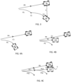
- Figure 4A shows a schematic view of an example embodiment of a robotic work tool 100 according to the teachings herein.
- the robotic work tool 100 may be a robotic lawnmower 100.
- the robotic work tool 100 has travelled a distance along a (real) path to a calibration point C1.
- the robotic work tool 100 has determined a sensed position, as indicated by the sensed path PS, which both shows an incorrect position and heading.
- the robotic work tool 100 calibrates the direction sensor 181, and possibly one or more of the other deduced reckoning sensors 180.
- the calibration is made by the robotic work tool 100 stopping and standing still for a time period allowing the direction sensor 181 to be calibrated.
- the error is determined by the robotic work tool 100 determining a first sensed direction before the calibration is made, as indicated by the heading of the dashed robotic work tool 100 in figure 4A , and determining a second sensed direction, as indicated by the heading of the (full lines) robotic work tool 100 in figure 4A , after the calibration is made.
- the robotic work tool 100 is thereby enabled to determine the error as the difference in determined directions, i.e. the difference between the first and the second direction.
- the robotic work tool 100 determines a corrected path PC based on the determined error.
- the error may be approximated to be linear over time, and the robotic work tool 100 is thus able to interpolate the error back to a previous calibration point where a position for the robotic work tool 100 was determined. Knowing the final error, and that the error is increasing linearly, it is straightforward to determine the corrected path.
- the robotic work tool 100 is thereby configured and enabled to determine a corrected path by retroactively correcting for the drift or error in the direction sensor 181.
- the same assumption is made for other deduced reckoning sensors, and the robotic work tool 100 is thus configured and enabled to determine a corrected path by retroactively correcting for the drift or error also in the other deduced reckoning sensors 180.
- Figure 4B thus shows how a corrected position (as indicated by the dashed robotic work tool 100 in figure 4B ) can be determined based on a retroactive correction of the (direction) sensor input.
- Figure 4C shows an example of a robotic work tool 100 according to the teachings herein where the robotic work tool 100 is applying the teachings herein over more than one calibration (point).
- the retroactive correction of the position (and path) allows for a much smaller error E over time.
- the teachings herein exhibit significant benefits in being able to correct the position (retroactively), not only the direction, at each calibration point. Comparing the error E in figure 3 and the error E in figure 4C clearly shows this benefit in that the error E in figure 4C is much smaller than the error E in figure 3 .
- the IMU gyroscope delivers the orientation of the IMU.
- the orientation can be represented as yaw, pitch and roll.
- Yaw is the heading or direction in the plane of the IMU. It says in which direction the IMU is rotated, ie north, south etc, but in degrees or radians and only with a relative angle.
- the drift will integrate to an offset of the yaw added to the real word orientation. A large drift will change the offset faster compared to a small drift.
- the gyro will always have a base offset which is impossible to remove since the gyro has no knowledge about real world coordinates, or the gyro has no knowledge of true north compared to a compass which has this information.
- Roll and pitch can be calculated based on gravitation force, but the yaw must be calculated and integrated based on the centrifugal force. A small error in the force will lead to an unrecoverable error in the yaw. This is called drift. Temperature changes, voltage noise and several other sources will affect the drift. If the gyro yaw is not calibrated it will have a constant drift of yaw, with some radians per second.
- the gyro yaw can self-calibrate when it senses it is completely still. It will then measure the centrifugal force and assume this is the normal, or bias, force that should always be subtracted from the centrifugal before it is used for integration.
- One large contributor to changes in the centrifugal force is temperature changes. Therefore, the calibration needs to be redone several times, and especially when the temperature increases or decreases.
- the added centrifugal force from temperature changes is proportional to the temperature changes. So if the temperature changes +10 Kelvin the drift will changed double compared to a temperature change of +5 Kelvin. In some applications temperature compensations tables are used in the Gyro.
- the robotic work tool can assume that the drift was linear from last calibration to latest calibration. Once the robotic work tool has an estimate of the drift from last calibration, the robotic work tool can estimate the offset. Contemporary gyros normally adjusts the drift bias parameters but does no change in offset. As the robotic work tool estimates an offset is estimated, the robotic work tool is able to get a better estimate of the yaw in world coordinates and a better dead reckoning can be calculated. The trajectory from the dead reckoning is then recalculated from the earlier calibration.
- the teachings herein thus enable the robotic work tool to Use the measured forces from the lasts gyro calibration to estimate the drift over the complete period since the calibration before. Then add the new estimated drift to the gyro offset to get a better estimate of the true heading from the gyro calibration performed earlier up to the last gyro calibration.
- Figure 5 shows a flowchart for a general method according to herein.
- the method is for use in a robotic work tool as in figure 1 in a manner as discussed above in relation to figures 2 , 3, 4A, 4B and 4C , namely for use in a robotic work tool system comprising a robotic work tool 100 comprising a deduced reckoning sensor 180, which comprises a direction sensor (181), and wherein the method comprises receiving 510 sensor input from the deduced reckoning sensors 180, in particular from the direction sensor 181, and determining 520 a current sensed position of the robotic work tool 100 based on the received sensor input and a previous position of the robotic work tool 100.
- the method further comprises calibrating 530 the direction sensor, and determining 540 an error in sensor input.
- the method also comprises interpolating 550 the error in sensor input to the previous position, in order to retroactively determine a corrected position and/or path.
- the method thus further includes determining 560 a corrected position of the robotic work tool 100 based on the received sensor input, the interpolated error and the previous position of the robotic work tool 100.
- the robotic work tool further comprises a memory 120 being configured to store a map application 120A and to store data regarding a position of the robotic work tool 100, and wherein the method further comprises determining 560 the corrected position in the map application 120A.
- the method further comprises interpolating 550 the error in sensor input to the previous position based on assumption that the error is drifting. And, in some such embodiments the method further comprises interpolating 550 the error in sensor input to the previous position based on assumption that the error is drifting by increasing linearly.
- the robotic work tool 100 is thus also configured to determine or detect a temperature, for example in the IMU.
- the IMU is then seen to comprise or be connected to a temperature sensor.
- the temperature sensor is deemed to be part of the deduced reckoning sensors.
- the robotic work tool is also configured to (retroactively) determine a dependency or proportionality between the error and the change in temperature. Such proportionality may be linear (as discussed above) or it may be of other forms. In either case, the dependency can be determined using regression analysis tools, which are considered to be known by a skilled person and require no further details.
- the method further comprises determining a sensed direction and to determine a corrected direction in addition to the positions being determined.
- the method further comprises determining 540 the error in sensor input by determining an error in direction. In some such embodiments this is made by determining 525 a first direction before the calibration, determining 535 a second direction after the calibration 530 and determining 540 the error as the difference between the first and the second directions.
- the method further comprises determining 520 the sensed position by determining a sensed path and determining 560 the corrected position by determining a corrected path.
- the paths are determined, as a skilled person would realize, based on the deduced sensor input from the deduced reckoning sensors 180, including the direction sensor 181.
- the method further comprises calibrating 530 the direction sensor 181 by controlling the robotic work tool 100 to stop and stand still for a time period allowing for the calibration of the direction sensor 181.
- Some examples include 20, 30, 40, 45, 50, 60, 70, 80, 90, 120, 150 or 180 seconds or any time period there in between.
- the direction sensor comprises at least one gyro sensor.
- the direction sensor is an IMU comprising the at least one gyro sensor.
- the calibration is made at intervals of 1, 5, 10 minutes or any range there in between.
- Figure 6 shows a schematic view of a computer-readable medium 600 carrying computer instructions 610 that when loaded into and executed by a controller of a device, such as a robotic work tool 100 or a server 240, enables the device to implement the teachings herein.
- the device will be exemplified as the robotic work tool 100.
- the computer-readable medium 600 may be tangible such as a hard drive or a flash memory, for example a USB memory stick or a cloud server.
- the computer-readable medium 600 may be intangible such as a signal carrying the computer instructions enabling the computer instructions to be downloaded through a network connection, such as an internet connection.
- a computer-readable medium 600 is shown as being a hard drive or computer disc 600 carrying computer-readable computer instructions 610, being inserted in a computer disc reader 620.
- the computer disc reader 620 may be part of a cloud server 630 - or other server - or the computer disc reader 620 may be connected to a cloud server 630 - or other server.
- the cloud server 630 may be part of the internet or at least connected to the internet.
- the cloud server 630 may alternatively be connected through a proprietary or dedicated connection.
- the computer instructions are stored at a remote server 630 and be downloaded to the memory 120 of the robotic work tool 100 for being executed by the controller 110.
- the computer disc reader 620 may also or alternatively be connected to (or possibly inserted into) a robotic work tool 100 for transferring the computer-readable computer instructions 610 to a controller of the robotic work tool 100 (presumably via a memory of the robotic work tool 100).
- Figure 6 shows both the situation when a robotic work tool 100 receives the computer-readable computer instructions 610 via a server connection and the situation when another robotic work tool 100 receives the computer-readable computer instructions 610 through a wired interface. This enables for computer-readable computer instructions 610 being downloaded into a robotic work tool 100 thereby enabling the robotic work tool 100 to operate according to and implement the invention as disclosed herein.
Landscapes
- Engineering & Computer Science (AREA)
- Radar, Positioning & Navigation (AREA)
- Remote Sensing (AREA)
- Physics & Mathematics (AREA)
- General Physics & Mathematics (AREA)
- Automation & Control Theory (AREA)
- Aviation & Aerospace Engineering (AREA)
- Life Sciences & Earth Sciences (AREA)
- Environmental Sciences (AREA)
- Control Of Position, Course, Altitude, Or Attitude Of Moving Bodies (AREA)
- Numerical Control (AREA)
- Manipulator (AREA)
Abstract
Description
- This application relates to a robotic work tool, such as a lawnmower, and a method for providing an improved determination of a position for the robotic work tool, and in particular to a robotic work tool, such as a lawnmower, and a method for providing an improved determination of a position for the robotic work tool utilizing deduced reckoning, and in particular to utilizing a gyro.
- Automated or robotic work tools such as robotic lawnmowers are becoming increasingly more popular and so is the use of the robotic work tool in various types of operational areas.
- Such robotic work tools, in particular for robotic work tools being robotic lawnmowers, are often required to operate in operational areas that include irregular surfaces (such as slopes), houses, vegetation and other objects and obstacles. Such robotic work tools are also often required to operate in specific patterns or subareas, where it becomes important to accurately determine a position of the robotic work tool.
- Prior art solutions rely on deduced reckoning for determining a position. The deduced reckoning may be used as the main mode of navigation or as a supplement to other navigation methods, such as based on satellite signals, beacon signals or other known navigation techniques.
- Deduced reckoning navigation often rely on odometry (such as wheel counts) and a direction sensor for determining a position and possibly a path to that position. However, direction sensors, as well as all sensors, often offer from an error which makes the determining of a position potentially inaccurate. Adding to this the error in direction sensors, especially for gyros or gyroscopes, increase over time, the error thus drifting, which makes it difficult to account for any error from the start, as the error will continue to grow.
- Thus, there is a need for an improved manner of providing advanced navigational functionality utilizing direction-sensing navigation while still utilizing cheap or uncomplicated sensors.
- It is therefore an object of the teachings of this application to overcome or at least reduce those problems by providing a robotic work tool system comprising a robotic work tool, the robotic work tool comprising a controller, a deduced reckoning sensor comprising a direction sensor, and wherein the controller is configured to receive sensor input from the deduced reckoning sensors, determine a current sensed position of the robotic work tool based on the received sensor input and a previous position of the robotic work tool, calibrate the direction sensor, determine an error in sensor input, interpolate the error in sensor input to the previous position, and determine a corrected position of the robotic work tool based on the received sensor input, the interpolated error and the previous position of the robotic work tool.
- Other embodiments are discussed in the description below and as per the claims.
- In some embodiments the robotic work tool is a robotic lawnmower.
- It is also an object of the teachings of this application to overcome the problems by providing a method for use in a robotic work tool system comprising a robotic work tool, the robotic work tool comprising a controller, a deduced reckoning sensor comprising a direction sensor, and wherein the method comprises: receiving sensor input from the deduced reckoning sensors, determining a current sensed position of the robotic work tool based on the received sensor input and a previous position of the robotic work tool, calibrating the direction sensor, determining an error in sensor input, interpolating the error in sensor input to the previous position, and determining a corrected position of the robotic work tool based on the received sensor input, the interpolated error and the previous position of the robotic work tool.
- It is also an object of the teachings of this application to overcome the problems by providing a computer-readable medium carrying computer instructions that when loaded into and executed by a controller of a robotic work tool enables the robotic work tool to implement the method according to herein.
- Further embodiments and aspects are as in the attached patent claims and as discussed in the detailed description.
- Other features and advantages of the disclosed embodiments will appear from the following detailed disclosure, from the attached dependent claims as well as from the drawings. Generally, all terms used in the claims are to be interpreted according to their ordinary meaning in the technical field, unless explicitly defined otherwise herein. All references to "a/an/the [element, device, component, means, step, etc.]" are to be interpreted openly as referring to at least one instance of the element, device, component, means, step, etc., unless explicitly stated otherwise. The steps of any method disclosed herein do not have to be performed in the exact order disclosed, unless explicitly stated.
- The invention will be described in further detail under reference to the accompanying drawings in which:
-
Figure 1 shows a schematic view of the components of an example of a robotic work tool being a robotic lawnmower according to some example embodiments of the teachings herein; -
Figure 2 shows a schematic view of a robotic work tool system according to some example embodiments of the teachings herein; -
Figure 3 shows a schematic view of a robotic work tool according to some examples of the problems addressed by the teachings herein; -
Figure 4A shows a schematic view of a robotic work tool system according to some example embodiments of the teachings herein; -
Figure 4B shows a schematic view of a robotic work tool system according to some example embodiments of the teachings herein; -
Figure 4C shows a schematic view of a robotic work tool system according to some example embodiments of the teachings herein; -
Figure 5 shows a corresponding flowchart for a method according to some example embodiments of the teachings herein; and -
Figure 6 shows a schematic view of a computer-readable medium carrying computer instructions that when loaded into and executed by a controller of a robotic work tool, enables the robotic work tool to implement the teachings herein. - The disclosed embodiments will now be described more fully hereinafter with reference to the accompanying drawings, in which certain embodiments of the invention are shown. This invention may, however, be embodied in many different forms and should not be construed as limited to the embodiments set forth herein. Like reference numbers refer to like elements throughout.
- It should be noted that even though the description given herein will be focused on robotic lawnmowers, the teachings herein may also be applied to, robotic ball collectors, robotic mine sweepers, robotic farming equipment, or other robotic work tools.
-
Figure 1 shows a schematic overview of arobotic work tool 100, here exemplified by arobotic lawnmower 100. Therobotic work tool 100 may be a multi-chassis type or a mono-chassis type (as infigure 1 ). A multi-chassis type comprises more than one main body parts that are movable with respect to one another. A mono-chassis type comprises only one main body part. - It should be noted that robotic lawnmower may be of different sizes, where the size ranges from merely a few decimetres for small garden robots, to even more than 1 meter for large robots arranged to service for example airfields.
- It should also be noted that the robotic work tool is a self-propelled robotic work tool, capable of autonomous navigation within an operational area, where the robotic work tool propels itself across or around the operational area in a pattern.
- The
robotic work tool 100, exemplified as arobotic lawnmower 100, has amain body part 140, possibly comprising achassis 140 and anouter shell 140A, and a plurality of wheels 130 (in this example four wheels 130, but other number of wheels are also possible, such as three or six). - The
main body part 140 substantially houses all components of therobotic lawnmower 100. At least some of the wheels 130 are drivably connected to at least oneelectric motor 155 powered by abattery 150. It should be noted that even if the description herein is focused on electric motors, combustion engines may alternatively be used, possibly in combination with an electric motor. In the example offigure 1 , each of the wheels 130 is connected to a common or to a respectiveelectric motor 155 for driving the wheels 130 to navigate therobotic lawnmower 100 in different manners. The wheels, themotor 155 and possibly thebattery 150 are thus examples of components making up a propulsion device. By controlling themotors 155, the propulsion device may be controlled to propel therobotic lawnmower 100 in a desired manner, and the propulsion device will therefore be seen as synonymous with the motor(s) 150. It should be noted that wheels 130 driven by electric motors is only one example of a propulsion system and other variants are possible such as caterpillar tracks. - The
robotic lawnmower 100 also comprises acontroller 110 and a computer readable storage medium ormemory 120. Thecontroller 110 may be implemented using instructions that enable hardware functionality, for example, by using executable computer program instructions in a general-purpose or special-purpose processor that may be stored on thememory 120 to be executed by such a processor. Thecontroller 110 is configured to read instructions from thememory 120 and execute these instructions to control the operation of therobotic lawnmower 100 including, but not being limited to, the propulsion and navigation of the robotic lawnmower. - The
controller 110 in combination with theelectric motor 155 and the wheels 130 forms the base of a navigation system (possibly comprising further components) for the robotic lawnmower, enabling it to be self-propelled as discussed. - The
controller 110 may be implemented using any suitable, available processor or Programmable Logic Circuit (PLC). Thememory 120 may be implemented using any commonly known technology for computer-readable memories such as ROM, FLASH, DDR, or some other memory technology. - The
robotic lawnmower 100 is further arranged with awireless communication interface 115 for communicating with other devices, such as a server, a personal computer, a smartphone, the charging station, and/or other robotic work tools. Examples of such wireless communication devices are Bluetooth®, WiFi® (IEEE802.11b), Global System Mobile (GSM) and LTE (Long Term Evolution), to name a few. Therobotic lawnmower 100 may be arranged to communicate with a user equipment (not shown but will be regarded as being an example of a server, as an example of a connected device) as discussed in relation tofigure 2 below for providing information regarding status, location, and progress of operation to the user equipment as well as receiving commands or settings from the user equipment. The server is not shown explicitly infigure 1 (nor infigure 2 ), but may be seen as the server referenced 630 infigure 6 . Alternatively or additionally, therobotic lawnmower 100 may be arranged to communicate with a server for providing information regarding status, location, and progress of operation as well as receiving commands or settings. - The
robotic lawnmower 100 also comprises a work tool 160, which in the example of therobotic lawnmower 100 is a grass cutting device 160, such as a rotating blade 160/2 driven by a cutter motor 160/1. In embodiments where therobotic work tool 100 is exemplified as an automatic grinder, the work tool 160 is a rotating grinding disc. - For enabling the
robotic lawnmower 100 to navigate with reference to a wire, such as a boundary wire or a guide wire, emitting a magnetic field caused by a control signal transmitted through the wire, therobotic lawnmower 100 is, in some embodiments, configured to have at least onemagnetic field sensor 170 arranged to detect the magnetic field and for detecting the wire and/or for receiving (and possibly also sending) information to/from a signal generator. In some embodiments, such a magnetic boundary is used to provide a border (not shown explicitly infigure 2 , but deemed to be included in the boundary 220) enclosing an operational area (referenced 205 infigure 2 ). - In some embodiments the
robotic lawnmower 100 comprises a satellitesignal navigation sensor 175 configured to provide navigational information (such as position) based on receiving one or more signals from a satellite - possibly in combination with receiving a signal from a base station. In some embodiments the satellite navigation sensor is a GPS (Global Positioning System) device or other Global Navigation Satellite System (GNSS) device. In some embodiments thesatellite navigation sensor 175 is a RTK sensor. This enables the robotic work tool to operate in an operational area bounded by a virtual border (not shown explicitly infigure 2 but deemed to be included in the boundary 220). - The
robotic lawnmower 100 also comprises deducedreckoning sensors 180. The deduced reckoning sensors may be odometers, accelerometers or other deduced reckoning sensors. Specifically, the deducedreckoning sensors 180 comprises one ormore direction sensors 181 configured to determine a current direction and/or any direction changes for therobotic work tool 100. In some embodiments the one ormore direction sensors 181 includes at least one gyro or gyroscopic sensor. In some embodiments the one ormore direction sensors 181 includes an Inertial Measurement Unit (IMU) comprising the at least one gyro or gyroscopic sensor. An inertial measurement unit (IMU) is an electronic device that measures and reports a body's specific force, angular rate, and sometimes the orientation of the body, using a combination of accelerometers, gyroscopes, and sometimes magnetometers. The at least one gyroscope provides a measured or sensed angular rate. The at least one accelerometer provides a measured or sensed specific force/acceleration. And the at least one magnetometer (optional) provides a measured or sensed magnetic field surrounding the body. Typical configurations contain one accelerometer, gyro, and magnetometer per axis for each of the three principal axes: pitch, roll and yaw. - As the inventors have realized environmental factors may cause any of these sensors to drift. Specifically, temperature changes, both caused by the environment as well as caused by components in the robotic work tool, may cause a drift. This drift, as the inventors have realized after inventive reasoning builds up over time and can be approximated or assumed to be linear - at least over shorter time periods, such as useful in the context of robotic work tools, and, in particular, robotic lawnmowers.
- The
robotic lawnmower 100 is in some embodiments arranged to operate according to a map application (indicated infigure 2 and referenced 120A) representing one or more operational areas (and possibly the surroundings of the operational area(s)) as well as features of the operational area(s) stored in thememory 120 of therobotic lawnmower 100. In some embodiments, the map is also or alternatively stored in the memory of a server. The map application may be generated or supplemented as therobotic lawnmower 100 operates or otherwise moves around in the operational area. In some embodiments, the map application is downloaded, possibly from the server. In some embodiments, the map application also includes one or more transport areas. Therobotic work tool 100 is arranged to navigate according to the map based on the deducedreckoning sensors 180. -
Figure 2 shows a roboticwork tool system 200 in some embodiments. The schematic view is not to scale. The roboticwork tool system 200 comprises one or morerobotic work tools 100 according to the teachings herein arranged to operate in one or moreoperational areas 205 possibly bounded by aboundary 220. It should be noted that theoperational area 205 shown infigure 2 is simplified for illustrative purposes. - The view of the
operational area 205 is also intended to be an illustration or graphical representation of themap application 120A discussed in the above. - A server (not shown) may be an optional connected device for the
robotic work tool 100 to communicate with - possibly for receiving maps or map updates. The server is not shown explicitly infigure 2 (nor infigure 1 ) but may be seen as the server referenced 630 infigure 6 . The server comprises a controller for controlling the operation of the server, a memory for storing instructions and data relating to the operation of the server and a communication interface for enabling the server to communicate with other entities, such as therobotic work tool 100, and/or a User Equipment such as a mobile phone. The controller, the memory and the communication interface may be of similar types as discussed in relation tofigure 1 for therobotic work tool 100. - As with
figure 1 , the robotic work tool(s) is exemplified by a robotic lawnmower, whereby the robotic work tool system may be a robotic lawnmower system or a system comprising a combinations of robotic work tools, one being a robotic lawnmower, but the teachings herein may also be applied to other robotic work tools adapted to operate within an operational area. - As is shown in
figure 2 there may be obstacles such as houses H or other structures, vegetation V, such as trees or bushes, and/or slopes S to mention a few examples of obstacles or objects in anoperational area 205. -
Figure 3 shows a situation where a prior artrobotic work tool 10 is navigating along a path PR. The position (and possibly the path) of therobotic work tool 10 is be determined based on the deduced reckoning sensors usually by determining a speed or a distance travelled and a heading, which gives the position. The speed is in some embodiments determined based on odometry sensors or other deduced reckoning sensors. Similarly, the distance travelled may also be determined based on odometry sensors or other deduced reckoning sensors. - As is also illustrated in
figure 3 , the deduced reckoning sensors, and in particular any direction sensor, may suffer from an error, whereby a sensed path PS will differ from the real path PR. This will result in that a position determined for therobotic work tool 10 based on the deduced reckoning sensors will differ from the real position. Infigure 3 the determined or sensed position is illustrated as arobotic work tool 10, but with dashed lines indicating the virtual representation of therobotic work tool 10 in a map application. - As is also illustrated the error in the sensed path grows over time. This is illustrated by the sensed path not being straight as the real path. To overcome such drift in the deduced reckoning sensors, the prior art
robotic work tools 10 are arranged to calibrate the deduced reckoning sensors, and in particular the direction sensors. This is illustrated infigure 3 as in that the sensed path after a calibration at point C1, shows a smaller error compared to the real path. - However, and as the inventors have realized, this leads to an accumulated error in position as is shown in
figure 3 by the error E being indicted as a second calibration point C2. Prior art solutions exist which calibrate and correct for this error E based on an alternatively determined position, such as through satellite (GPS for example) navigation. However, and as the inventors have also realized, this is only possible if the robotic work tool is arranged with such advanced navigation devices, and it is also only possibly in areas where reliable navigation is possible. For example, a satellite navigation sensor may not receive enough satellite sensors when under vegetation or behind a structure, to enable an accurate determination of a position. In such instances, there may be a lengthy time period before the position is actually corrected, which may lead to that therobotic work tool 10 is unable to perform a required operating pattern, or that the robotic work tool may navigate incorrectly as regards the map application and end up in a position which may be harmful or may cause the robotic work tool to get stuck. - Any attempt at simply calibrating the (direction) sensors more often to keep the error small will, however, result in the
robotic work tool 10 stopping often to allow for the calibration of the direction sensor, which both wastes operating time and may be confusing to a user seeing the robotic work tool stopping all the time. - The inventors have, however, realized that by assuming or approximating the drift (or error) to be linear, the position at each calibration can be corrected.
-
Figure 4A shows a schematic view of an example embodiment of arobotic work tool 100 according to the teachings herein. As in the examples offigure 1 and 2 , therobotic work tool 100 may be arobotic lawnmower 100. In the example offigure 4A therobotic work tool 100 has travelled a distance along a (real) path to a calibration point C1. At this calibration point C1, therobotic work tool 100 has determined a sensed position, as indicated by the sensed path PS, which both shows an incorrect position and heading. At this calibration position C1, therobotic work tool 100 calibrates thedirection sensor 181, and possibly one or more of the other deducedreckoning sensors 180. The calibration is made by therobotic work tool 100 stopping and standing still for a time period allowing thedirection sensor 181 to be calibrated. - After the calibration is done, an error in the
direction sensor 181 is determined. - In some embodiments the error is determined by the
robotic work tool 100 determining a first sensed direction before the calibration is made, as indicated by the heading of the dashedrobotic work tool 100 infigure 4A , and determining a second sensed direction, as indicated by the heading of the (full lines)robotic work tool 100 infigure 4A , after the calibration is made. - The
robotic work tool 100 is thereby enabled to determine the error as the difference in determined directions, i.e. the difference between the first and the second direction. - As is illustrated in
figure 4B , therobotic work tool 100 then determines a corrected path PC based on the determined error. As discussed in the above and as the inventors have realized, the error may be approximated to be linear over time, and therobotic work tool 100 is thus able to interpolate the error back to a previous calibration point where a position for therobotic work tool 100 was determined. Knowing the final error, and that the error is increasing linearly, it is straightforward to determine the corrected path. - The
robotic work tool 100 is thereby configured and enabled to determine a corrected path by retroactively correcting for the drift or error in thedirection sensor 181. - In some embodiments, the same assumption is made for other deduced reckoning sensors, and the
robotic work tool 100 is thus configured and enabled to determine a corrected path by retroactively correcting for the drift or error also in the other deducedreckoning sensors 180. -
Figure 4B thus shows how a corrected position (as indicated by the dashedrobotic work tool 100 infigure 4B ) can be determined based on a retroactive correction of the (direction) sensor input. -
Figure 4C shows an example of arobotic work tool 100 according to the teachings herein where therobotic work tool 100 is applying the teachings herein over more than one calibration (point). As can be seen infigure 4C , the retroactive correction of the position (and path) allows for a much smaller error E over time. As the errors at each calibration point are accumulated over time, the teachings herein exhibit significant benefits in being able to correct the position (retroactively), not only the direction, at each calibration point. Comparing the error E infigure 3 and the error E infigure 4C clearly shows this benefit in that the error E infigure 4C is much smaller than the error E infigure 3 . - It should be noted that any error indicated in
figures 3, 4A, 4B or 4C is only for illustrative purposes and are not to scale. Similarly, it should also be noted that the continued paths after a calibration point may or may not be illustrated in the correct starting heading, but the paths are only shown for illustrative purposes and are not to scale. - In the following some further details to what is discussed in the above with regards to directions sensors, such as IMUs, is discussed. The IMU gyroscope delivers the orientation of the IMU. The orientation can be represented as yaw, pitch and roll. Yaw is the heading or direction in the plane of the IMU. It says in which direction the IMU is rotated, ie north, south etc, but in degrees or radians and only with a relative angle. The drift will integrate to an offset of the yaw added to the real word orientation. A large drift will change the offset faster compared to a small drift. The gyro will always have a base offset which is impossible to remove since the gyro has no knowledge about real world coordinates, or the gyro has no knowledge of true north compared to a compass which has this information. Roll and pitch can be calculated based on gravitation force, but the yaw must be calculated and integrated based on the centrifugal force. A small error in the force will lead to an unrecoverable error in the yaw. This is called drift. Temperature changes, voltage noise and several other sources will affect the drift. If the gyro yaw is not calibrated it will have a constant drift of yaw, with some radians per second. The gyro yaw can self-calibrate when it senses it is completely still. It will then measure the centrifugal force and assume this is the normal, or bias, force that should always be subtracted from the centrifugal before it is used for integration. One large contributor to changes in the centrifugal force is temperature changes. Therefore, the calibration needs to be redone several times, and especially when the temperature increases or decreases. The added centrifugal force from temperature changes is proportional to the temperature changes. So if the temperature changes +10 Kelvin the drift will changed double compared to a temperature change of +5 Kelvin. In some applications temperature compensations tables are used in the Gyro. Since the temperature changes is one of the largest contributors to drift and temperature changes typically changes linear during a small time interval we can assume that drift will change linear during the same time interval. So it may change from 0mrad/s to 10mrad/s for instance. The teachings herein thus teach that the robotic work tool can assume that the drift was linear from last calibration to latest calibration. Once the robotic work tool has an estimate of the drift from last calibration, the robotic work tool can estimate the offset. Contemporary gyros normally adjusts the drift bias parameters but does no change in offset. As the robotic work tool estimates an offset is estimated, the robotic work tool is able to get a better estimate of the yaw in world coordinates and a better dead reckoning can be calculated. The trajectory from the dead reckoning is then recalculated from the earlier calibration.
- The teachings herein thus enable the robotic work tool to Use the measured forces from the lasts gyro calibration to estimate the drift over the complete period since the calibration before. Then add the new estimated drift to the gyro offset to get a better estimate of the true heading from the gyro calibration performed earlier up to the last gyro calibration.
-
Figure 5 shows a flowchart for a general method according to herein. The method is for use in a robotic work tool as infigure 1 in a manner as discussed above in relation tofigures 2 ,3, 4A, 4B and 4C , namely for use in a robotic work tool system comprising arobotic work tool 100 comprising a deducedreckoning sensor 180, which comprises a direction sensor (181), and wherein the method comprises receiving 510 sensor input from the deducedreckoning sensors 180, in particular from thedirection sensor 181, and determining 520 a current sensed position of therobotic work tool 100 based on the received sensor input and a previous position of therobotic work tool 100. The method further comprises calibrating 530 the direction sensor, and determining 540 an error in sensor input. The method also comprises interpolating 550 the error in sensor input to the previous position, in order to retroactively determine a corrected position and/or path. The method thus further includes determining 560 a corrected position of therobotic work tool 100 based on the received sensor input, the interpolated error and the previous position of therobotic work tool 100. - In some embodiments the robotic work tool further comprises a
memory 120 being configured to store amap application 120A and to store data regarding a position of therobotic work tool 100, and wherein the method further comprises determining 560 the corrected position in themap application 120A. - In some embodiments the method further comprises interpolating 550 the error in sensor input to the previous position based on assumption that the error is drifting. And, in some such embodiments the method further comprises interpolating 550 the error in sensor input to the previous position based on assumption that the error is drifting by increasing linearly.
- It should be noted that the inventors have also realized that the error may not only increase or change linearly, but also or alternatively proportional to the surrounding temperature, and specifically the temperature in or adjacent to the IMU. In some additional or alternative embodiments the
robotic work tool 100 is thus also configured to determine or detect a temperature, for example in the IMU. In such embodiments the IMU is then seen to comprise or be connected to a temperature sensor. For other embodiments the temperature sensor is deemed to be part of the deduced reckoning sensors. The robotic work tool is also configured to (retroactively) determine a dependency or proportionality between the error and the change in temperature. Such proportionality may be linear (as discussed above) or it may be of other forms. In either case, the dependency can be determined using regression analysis tools, which are considered to be known by a skilled person and require no further details. - As discussed in the above, in some embodiments the method further comprises determining a sensed direction and to determine a corrected direction in addition to the positions being determined.
- In some embodiments the method further comprises determining 540 the error in sensor input by determining an error in direction. In some such embodiments this is made by determining 525 a first direction before the calibration, determining 535 a second direction after the
calibration 530 and determining 540 the error as the difference between the first and the second directions. - In some embodiments the method further comprises determining 520 the sensed position by determining a sensed path and determining 560 the corrected position by determining a corrected path. The paths are determined, as a skilled person would realize, based on the deduced sensor input from the deduced
reckoning sensors 180, including thedirection sensor 181. - In some embodiments the method further comprises calibrating 530 the
direction sensor 181 by controlling therobotic work tool 100 to stop and stand still for a time period allowing for the calibration of thedirection sensor 181. Some examples include 20, 30, 40, 45, 50, 60, 70, 80, 90, 120, 150 or 180 seconds or any time period there in between. - In some embodiments the direction sensor comprises at least one gyro sensor.
- In some embodiments the direction sensor is an IMU comprising the at least one gyro sensor.
- As mentioned above, this allows for maintaining a small error in determined position which allows for fewer calibrations of the robotic work tool. In some embodiments the calibration is made at intervals of 1, 5, 10 minutes or any range there in between.
-
Figure 6 shows a schematic view of a computer-readable medium 600 carryingcomputer instructions 610 that when loaded into and executed by a controller of a device, such as arobotic work tool 100 or a server 240, enables the device to implement the teachings herein. In the example offigure 6 , the device will be exemplified as therobotic work tool 100. The computer-readable medium 600 may be tangible such as a hard drive or a flash memory, for example a USB memory stick or a cloud server. Alternatively, the computer-readable medium 600 may be intangible such as a signal carrying the computer instructions enabling the computer instructions to be downloaded through a network connection, such as an internet connection. In the example offigure 6 , a computer-readable medium 600 is shown as being a hard drive orcomputer disc 600 carrying computer-readable computer instructions 610, being inserted in acomputer disc reader 620. Thecomputer disc reader 620 may be part of a cloud server 630 - or other server - or thecomputer disc reader 620 may be connected to a cloud server 630 - or other server. Thecloud server 630 may be part of the internet or at least connected to the internet. Thecloud server 630 may alternatively be connected through a proprietary or dedicated connection. In one example embodiment, the computer instructions are stored at aremote server 630 and be downloaded to thememory 120 of therobotic work tool 100 for being executed by thecontroller 110. - The
computer disc reader 620 may also or alternatively be connected to (or possibly inserted into) arobotic work tool 100 for transferring the computer-readable computer instructions 610 to a controller of the robotic work tool 100 (presumably via a memory of the robotic work tool 100). -
Figure 6 shows both the situation when arobotic work tool 100 receives the computer-readable computer instructions 610 via a server connection and the situation when anotherrobotic work tool 100 receives the computer-readable computer instructions 610 through a wired interface. This enables for computer-readable computer instructions 610 being downloaded into arobotic work tool 100 thereby enabling therobotic work tool 100 to operate according to and implement the invention as disclosed herein.
Claims (15)
- A robotic work tool system comprising a robotic work tool (100), the robotic work tool comprising a controller (110), a deduced reckoning sensor (180) comprising a direction sensor (181), and wherein the controller (110) is configured toreceive sensor input from the deduced reckoning sensors (180),determine a current sensed position of the robotic work tool (100) based on the received sensor input and a previous position of the robotic work tool (100),calibrate the direction sensor,determine an error in sensor input,interpolate the error in sensor input to the previous position, anddetermine a corrected position of the robotic work tool (100) based on the received sensor input, the interpolated error and the previous position of the robotic work tool (100).
- The robotic work tool system (200) according to claim 1, wherein the robotic work tool further comprises a memory (120) being configured to store a map application (120A) and to store data regarding a position of the robotic work tool (100), and wherein the controller is further configured to determine the corrected position in the map application (120A).
- The robotic work tool system (200) according to any preceding claim, wherein the controller is further configured to interpolate the error in sensor input to the previous position based on assumption that the error is drifting.
- The robotic work tool system (200) according to claim 3, wherein the controller is further configured to interpolate the error in sensor input to the previous position based on assumption that the error is drifting by increasing proportionally to a temperature.
- The robotic work tool system (200) according to claim 3 or 4, wherein the controller is further configured to interpolate the error in sensor input to the previous position based on assumption that the error is drifting by increasing linearly.
- The robotic work tool system (200) according to any preceding claim, wherein the controller is further configured to determine a sensed direction and to determine a corrected direction.
- The robotic work tool system (200) according to any preceding claim, wherein the controller is further configured to determine the error in sensor input by determining an error in direction.
- The robotic work tool system (200) according to any preceding claim, wherein the controller is further configured todetermine the sensed position by determining a sensed path and todetermine the corrected position by determining a corrected path.
- The robotic work tool system (200) according to any preceding claim, wherein the controller is further configured to calibrate the direction sensor (181) by controlling the robotic work tool (100) to stop and stand still for a time period allowing for the calibration of the direction sensor (181).
- The robotic work tool system (200) according to any preceding claim, wherein the direction sensor comprises at least one gyro sensor.
- The robotic work tool system (200) according to claim 10, wherein the direction sensor is an IMU comprising the at least one gyro sensor.
- The robotic work tool system (200) according to claim 4 and 11, wherein the temperature is a temperature in or adjacent the IMU.
- The robotic work tool system (200) according to any preceding claim, wherein the robotic work tool (100) is a robotic lawnmower (100).
- A method for use in a robotic work tool system comprising a robotic work tool (100), the robotic work tool comprising a controller (110), a deduced reckoning sensor (180) comprising a direction sensor (181), and wherein the method comprises:receiving sensor input from the deduced reckoning sensors (180),determining a current sensed position of the robotic work tool (100) based on the received sensor input and a previous position of the robotic work tool (100),calibrating the direction sensor,determining an error in sensor input,interpolating the error in sensor input to the previous position, anddetermining a corrected position of the robotic work tool (100) based on the received sensor input, the interpolated error and the previous position of the robotic work tool (100).
- A computer-readable medium (600) carrying computer instructions (610) that when loaded into and executed by a controller (110) of a robotic work tool (100) enables the robotic work tool (100) to implement the method according to claim 14.
Applications Claiming Priority (1)
| Application Number | Priority Date | Filing Date | Title |
|---|---|---|---|
| SE2350121A SE547035C2 (en) | 2023-02-10 | 2023-02-10 | Improved determination of pose for a robotic work tool based on a calibrated direction sensor and an interpolated error in sensor input |
Publications (2)
| Publication Number | Publication Date |
|---|---|
| EP4414804A1 true EP4414804A1 (en) | 2024-08-14 |
| EP4414804B1 EP4414804B1 (en) | 2025-11-19 |
Family
ID=89222600
Family Applications (1)
| Application Number | Title | Priority Date | Filing Date |
|---|---|---|---|
| EP23216626.4A Active EP4414804B1 (en) | 2023-02-10 | 2023-12-14 | Improved determination of pose for a robotic work tool |
Country Status (2)
| Country | Link |
|---|---|
| EP (1) | EP4414804B1 (en) |
| SE (1) | SE547035C2 (en) |
Citations (3)
| Publication number | Priority date | Publication date | Assignee | Title |
|---|---|---|---|---|
| US20160278285A1 (en) * | 2013-11-12 | 2016-09-29 | Husqvarna Ab | Improved navigation for a robotic working tool |
| US20210141044A1 (en) * | 2018-06-25 | 2021-05-13 | Gatekeeper Systems, Inc. | Dual magnetometer calibration |
| US20220276053A1 (en) * | 2021-02-18 | 2022-09-01 | Trimble Inc | Range image aided ins |
Family Cites Families (4)
| Publication number | Priority date | Publication date | Assignee | Title |
|---|---|---|---|---|
| US5559696A (en) * | 1994-02-14 | 1996-09-24 | The Regents Of The University Of Michigan | Mobile robot internal position error correction system |
| KR101214143B1 (en) * | 2008-12-22 | 2012-12-20 | 한국전자통신연구원 | Method and apparatus for detecting position and orientation |
| US8818420B2 (en) * | 2012-09-28 | 2014-08-26 | Intel Corporation | Rotation-tolerant devices and schemes for pedestrian-dead-reckoning (PDR) location determination |
| EP2827101A1 (en) * | 2013-07-18 | 2015-01-21 | Astrium GmbH | Method for determing a position of a tracking device |
-
2023
- 2023-02-10 SE SE2350121A patent/SE547035C2/en unknown
- 2023-12-14 EP EP23216626.4A patent/EP4414804B1/en active Active
Patent Citations (3)
| Publication number | Priority date | Publication date | Assignee | Title |
|---|---|---|---|---|
| US20160278285A1 (en) * | 2013-11-12 | 2016-09-29 | Husqvarna Ab | Improved navigation for a robotic working tool |
| US20210141044A1 (en) * | 2018-06-25 | 2021-05-13 | Gatekeeper Systems, Inc. | Dual magnetometer calibration |
| US20220276053A1 (en) * | 2021-02-18 | 2022-09-01 | Trimble Inc | Range image aided ins |
Also Published As
| Publication number | Publication date |
|---|---|
| SE547035C2 (en) | 2025-04-08 |
| EP4414804B1 (en) | 2025-11-19 |
| SE2350121A1 (en) | 2024-08-11 |
Similar Documents
| Publication | Publication Date | Title |
|---|---|---|
| US10606279B2 (en) | 3D map generation by a robotic work tool | |
| EP3069204B1 (en) | Improved navigation for a robotic working tool | |
| EP3084542B1 (en) | System and method for navigating a robotic working tool. | |
| EP3237927B1 (en) | Improved navigation for a robotic work tool | |
| EP3069203B1 (en) | Improved navigation for a robotic working tool | |
| US10093355B1 (en) | Vehicle automatic power and driving control | |
| CN108226965A (en) | From positioning failure processing method, device and the electronic equipment of mobile equipment | |
| WO2019104581A1 (en) | Track generating method and apparatus, and unmanned ground vehicle | |
| WO2017133707A1 (en) | Automatic operating system, self-moving device and control method thereof | |
| US20170144704A1 (en) | Method for guiding an off-road vehicle along a curved path | |
| EP4314974A1 (en) | Improved navigation for a robotic work tool | |
| EP4414804B1 (en) | Improved determination of pose for a robotic work tool | |
| EP4560426B1 (en) | Improved visual navigation for a robotic work tool | |
| Davidson et al. | Using low-cost MEMS 3D accelerometer and one gyro to assist GPS based car navigation system | |
| US20240407290A1 (en) | Navigation for a robotic lawnmower system | |
| US20240411320A1 (en) | Nagivation for a robotic lawnmower system | |
| EP4546074A1 (en) | Improved navigation for a robotic work tool system | |
| EP4552000A1 (en) | Improved determination of pose for a robotic work tool | |
| EP4535983A1 (en) | Improved navigation for a robotic work tool system | |
| US20240199080A1 (en) | Definition of boundary for a robotic work tool | |
| CN121553178A (en) | Automatic driving power-on control method, device, automatic driving equipment and storage medium | |
| SE2251415A1 (en) | Improved detection of a solar panel for a robotic work tool | |
| WO2020158290A1 (en) | Growth information management device, growth information management system, growth information management device control method and growth information management program |
Legal Events
| Date | Code | Title | Description |
|---|---|---|---|
| PUAI | Public reference made under article 153(3) epc to a published international application that has entered the european phase |
Free format text: ORIGINAL CODE: 0009012 |
|
| STAA | Information on the status of an ep patent application or granted ep patent |
Free format text: STATUS: REQUEST FOR EXAMINATION WAS MADE |
|
| 17P | Request for examination filed |
Effective date: 20231214 |
|
| AK | Designated contracting states |
Kind code of ref document: A1 Designated state(s): AL AT BE BG CH CY CZ DE DK EE ES FI FR GB GR HR HU IE IS IT LI LT LU LV MC ME MK MT NL NO PL PT RO RS SE SI SK SM TR |
|
| GRAP | Despatch of communication of intention to grant a patent |
Free format text: ORIGINAL CODE: EPIDOSNIGR1 |
|
| STAA | Information on the status of an ep patent application or granted ep patent |
Free format text: STATUS: GRANT OF PATENT IS INTENDED |
|
| RIC1 | Information provided on ipc code assigned before grant |
Ipc: G05D 1/245 20240101AFI20250619BHEP Ipc: G01C 21/00 20060101ALI20250619BHEP Ipc: G05D 1/246 20240101ALI20250619BHEP Ipc: G05D 1/248 20240101ALI20250619BHEP Ipc: G05D 105/15 20240101ALI20250619BHEP Ipc: G05D 107/20 20240101ALI20250619BHEP Ipc: G05D 109/10 20240101ALI20250619BHEP Ipc: G05D 111/50 20240101ALI20250619BHEP |
|
| INTG | Intention to grant announced |
Effective date: 20250709 |
|
| GRAS | Grant fee paid |
Free format text: ORIGINAL CODE: EPIDOSNIGR3 |
|
| P01 | Opt-out of the competence of the unified patent court (upc) registered |
Free format text: CASE NUMBER: UPC_APP_6390_4414804/2025 Effective date: 20250909 |
|
| GRAA | (expected) grant |
Free format text: ORIGINAL CODE: 0009210 |
|
| STAA | Information on the status of an ep patent application or granted ep patent |
Free format text: STATUS: THE PATENT HAS BEEN GRANTED |
|
| AK | Designated contracting states |
Kind code of ref document: B1 Designated state(s): AL AT BE BG CH CY CZ DE DK EE ES FI FR GB GR HR HU IE IS IT LI LT LU LV MC ME MK MT NL NO PL PT RO RS SE SI SK SM TR |
|
| REG | Reference to a national code |
Ref country code: CH Ref legal event code: F10 Free format text: ST27 STATUS EVENT CODE: U-0-0-F10-F00 (AS PROVIDED BY THE NATIONAL OFFICE) Effective date: 20251119 Ref country code: GB Ref legal event code: FG4D |
|
| REG | Reference to a national code |
Ref country code: DE Ref legal event code: R096 Ref document number: 602023008753 Country of ref document: DE |
|
| REG | Reference to a national code |
Ref country code: IE Ref legal event code: FG4D |
|
| PGFP | Annual fee paid to national office [announced via postgrant information from national office to epo] |
Ref country code: DE Payment date: 20251112 Year of fee payment: 3 |
|
| PGFP | Annual fee paid to national office [announced via postgrant information from national office to epo] |
Ref country code: AT Payment date: 20260113 Year of fee payment: 3 |
|
| REG | Reference to a national code |
Ref country code: NL Ref legal event code: MP Effective date: 20251119 |
|
| PG25 | Lapsed in a contracting state [announced via postgrant information from national office to epo] |
Ref country code: ES Free format text: LAPSE BECAUSE OF FAILURE TO SUBMIT A TRANSLATION OF THE DESCRIPTION OR TO PAY THE FEE WITHIN THE PRESCRIBED TIME-LIMIT Effective date: 20251119 |
|
| REG | Reference to a national code |
Ref country code: LT Ref legal event code: MG9D |
|
| PG25 | Lapsed in a contracting state [announced via postgrant information from national office to epo] |
Ref country code: NO Free format text: LAPSE BECAUSE OF FAILURE TO SUBMIT A TRANSLATION OF THE DESCRIPTION OR TO PAY THE FEE WITHIN THE PRESCRIBED TIME-LIMIT Effective date: 20260219 |
|
| PG25 | Lapsed in a contracting state [announced via postgrant information from national office to epo] |
Ref country code: FI Free format text: LAPSE BECAUSE OF FAILURE TO SUBMIT A TRANSLATION OF THE DESCRIPTION OR TO PAY THE FEE WITHIN THE PRESCRIBED TIME-LIMIT Effective date: 20251119 Ref country code: AT Free format text: LAPSE BECAUSE OF FAILURE TO SUBMIT A TRANSLATION OF THE DESCRIPTION OR TO PAY THE FEE WITHIN THE PRESCRIBED TIME-LIMIT Effective date: 20251119 Ref country code: HR Free format text: LAPSE BECAUSE OF FAILURE TO SUBMIT A TRANSLATION OF THE DESCRIPTION OR TO PAY THE FEE WITHIN THE PRESCRIBED TIME-LIMIT Effective date: 20251119 |
|
| REG | Reference to a national code |
Ref country code: AT Ref legal event code: MK05 Ref document number: 1859353 Country of ref document: AT Kind code of ref document: T Effective date: 20251119 |
|
| PG25 | Lapsed in a contracting state [announced via postgrant information from national office to epo] |
Ref country code: NL Free format text: LAPSE BECAUSE OF FAILURE TO SUBMIT A TRANSLATION OF THE DESCRIPTION OR TO PAY THE FEE WITHIN THE PRESCRIBED TIME-LIMIT Effective date: 20251119 |
|
| PG25 | Lapsed in a contracting state [announced via postgrant information from national office to epo] |
Ref country code: RS Free format text: LAPSE BECAUSE OF FAILURE TO SUBMIT A TRANSLATION OF THE DESCRIPTION OR TO PAY THE FEE WITHIN THE PRESCRIBED TIME-LIMIT Effective date: 20260219 |
|
| PG25 | Lapsed in a contracting state [announced via postgrant information from national office to epo] |
Ref country code: IS Free format text: LAPSE BECAUSE OF FAILURE TO SUBMIT A TRANSLATION OF THE DESCRIPTION OR TO PAY THE FEE WITHIN THE PRESCRIBED TIME-LIMIT Effective date: 20260319 |
|
| PG25 | Lapsed in a contracting state [announced via postgrant information from national office to epo] |
Ref country code: PT Free format text: LAPSE BECAUSE OF FAILURE TO SUBMIT A TRANSLATION OF THE DESCRIPTION OR TO PAY THE FEE WITHIN THE PRESCRIBED TIME-LIMIT Effective date: 20260319 |
|
| PG25 | Lapsed in a contracting state [announced via postgrant information from national office to epo] |
Ref country code: PL Free format text: LAPSE BECAUSE OF FAILURE TO SUBMIT A TRANSLATION OF THE DESCRIPTION OR TO PAY THE FEE WITHIN THE PRESCRIBED TIME-LIMIT Effective date: 20251119 |
|
| PG25 | Lapsed in a contracting state [announced via postgrant information from national office to epo] |
Ref country code: LV Free format text: LAPSE BECAUSE OF FAILURE TO SUBMIT A TRANSLATION OF THE DESCRIPTION OR TO PAY THE FEE WITHIN THE PRESCRIBED TIME-LIMIT Effective date: 20251119 |
|
| PG25 | Lapsed in a contracting state [announced via postgrant information from national office to epo] |
Ref country code: BG Free format text: LAPSE BECAUSE OF FAILURE TO SUBMIT A TRANSLATION OF THE DESCRIPTION OR TO PAY THE FEE WITHIN THE PRESCRIBED TIME-LIMIT Effective date: 20251119 |