EP4414770A1 - Image projecting device and image projecting method - Google Patents
Image projecting device and image projecting method Download PDFInfo
- Publication number
- EP4414770A1 EP4414770A1 EP22878359.3A EP22878359A EP4414770A1 EP 4414770 A1 EP4414770 A1 EP 4414770A1 EP 22878359 A EP22878359 A EP 22878359A EP 4414770 A1 EP4414770 A1 EP 4414770A1
- Authority
- EP
- European Patent Office
- Prior art keywords
- image
- light
- unit
- projecting device
- optical
- Prior art date
- Legal status (The legal status is an assumption and is not a legal conclusion. Google has not performed a legal analysis and makes no representation as to the accuracy of the status listed.)
- Withdrawn
Links
- 238000000034 method Methods 0.000 title claims description 34
- 230000003287 optical effect Effects 0.000 claims abstract description 126
- 238000012937 correction Methods 0.000 claims description 46
- 238000003384 imaging method Methods 0.000 claims description 32
- 230000008859 change Effects 0.000 claims description 19
- 238000001514 detection method Methods 0.000 claims description 17
- 239000011358 absorbing material Substances 0.000 claims description 4
- 230000005540 biological transmission Effects 0.000 claims description 4
- 238000010586 diagram Methods 0.000 description 24
- 238000013461 design Methods 0.000 description 13
- 230000001133 acceleration Effects 0.000 description 7
- 230000006872 improvement Effects 0.000 description 7
- 230000008569 process Effects 0.000 description 7
- 239000011521 glass Substances 0.000 description 5
- 238000004891 communication Methods 0.000 description 4
- 238000006073 displacement reaction Methods 0.000 description 4
- 238000002310 reflectometry Methods 0.000 description 4
- 230000004075 alteration Effects 0.000 description 3
- 239000004973 liquid crystal related substance Substances 0.000 description 3
- 239000000463 material Substances 0.000 description 3
- 230000000903 blocking effect Effects 0.000 description 2
- 230000007423 decrease Effects 0.000 description 2
- 230000006866 deterioration Effects 0.000 description 2
- 230000000694 effects Effects 0.000 description 2
- 230000001678 irradiating effect Effects 0.000 description 2
- 238000012545 processing Methods 0.000 description 2
- 239000005357 flat glass Substances 0.000 description 1
- 230000010365 information processing Effects 0.000 description 1
- 238000012986 modification Methods 0.000 description 1
- 230000004048 modification Effects 0.000 description 1
- 239000011347 resin Substances 0.000 description 1
- 229920005989 resin Polymers 0.000 description 1
Images


Classifications
-
- G—PHYSICS
- G02—OPTICS
- G02B—OPTICAL ELEMENTS, SYSTEMS OR APPARATUS
- G02B27/00—Optical systems or apparatus not provided for by any of the groups G02B1/00 - G02B26/00, G02B30/00
- G02B27/01—Head-up displays
-
- G—PHYSICS
- G02—OPTICS
- G02B—OPTICAL ELEMENTS, SYSTEMS OR APPARATUS
- G02B27/00—Optical systems or apparatus not provided for by any of the groups G02B1/00 - G02B26/00, G02B30/00
- G02B27/01—Head-up displays
- G02B27/0101—Head-up displays characterised by optical features
-
- B—PERFORMING OPERATIONS; TRANSPORTING
- B60—VEHICLES IN GENERAL
- B60K—ARRANGEMENT OR MOUNTING OF PROPULSION UNITS OR OF TRANSMISSIONS IN VEHICLES; ARRANGEMENT OR MOUNTING OF PLURAL DIVERSE PRIME-MOVERS IN VEHICLES; AUXILIARY DRIVES FOR VEHICLES; INSTRUMENTATION OR DASHBOARDS FOR VEHICLES; ARRANGEMENTS IN CONNECTION WITH COOLING, AIR INTAKE, GAS EXHAUST OR FUEL SUPPLY OF PROPULSION UNITS IN VEHICLES
- B60K35/00—Instruments specially adapted for vehicles; Arrangement of instruments in or on vehicles
- B60K35/20—Output arrangements, i.e. from vehicle to user, associated with vehicle functions or specially adapted therefor
- B60K35/21—Output arrangements, i.e. from vehicle to user, associated with vehicle functions or specially adapted therefor using visual output, e.g. blinking lights or matrix displays
- B60K35/213—Virtual instruments
-
- B—PERFORMING OPERATIONS; TRANSPORTING
- B60—VEHICLES IN GENERAL
- B60K—ARRANGEMENT OR MOUNTING OF PROPULSION UNITS OR OF TRANSMISSIONS IN VEHICLES; ARRANGEMENT OR MOUNTING OF PLURAL DIVERSE PRIME-MOVERS IN VEHICLES; AUXILIARY DRIVES FOR VEHICLES; INSTRUMENTATION OR DASHBOARDS FOR VEHICLES; ARRANGEMENTS IN CONNECTION WITH COOLING, AIR INTAKE, GAS EXHAUST OR FUEL SUPPLY OF PROPULSION UNITS IN VEHICLES
- B60K35/00—Instruments specially adapted for vehicles; Arrangement of instruments in or on vehicles
- B60K35/20—Output arrangements, i.e. from vehicle to user, associated with vehicle functions or specially adapted therefor
- B60K35/21—Output arrangements, i.e. from vehicle to user, associated with vehicle functions or specially adapted therefor using visual output, e.g. blinking lights or matrix displays
- B60K35/23—Head-up displays [HUD]
- B60K35/231—Head-up displays [HUD] characterised by their arrangement or structure for integration into vehicles
-
- B—PERFORMING OPERATIONS; TRANSPORTING
- B60—VEHICLES IN GENERAL
- B60K—ARRANGEMENT OR MOUNTING OF PROPULSION UNITS OR OF TRANSMISSIONS IN VEHICLES; ARRANGEMENT OR MOUNTING OF PLURAL DIVERSE PRIME-MOVERS IN VEHICLES; AUXILIARY DRIVES FOR VEHICLES; INSTRUMENTATION OR DASHBOARDS FOR VEHICLES; ARRANGEMENTS IN CONNECTION WITH COOLING, AIR INTAKE, GAS EXHAUST OR FUEL SUPPLY OF PROPULSION UNITS IN VEHICLES
- B60K35/00—Instruments specially adapted for vehicles; Arrangement of instruments in or on vehicles
- B60K35/20—Output arrangements, i.e. from vehicle to user, associated with vehicle functions or specially adapted therefor
- B60K35/29—Instruments characterised by the way in which information is handled, e.g. showing information on plural displays or prioritising information according to driving conditions
-
- B—PERFORMING OPERATIONS; TRANSPORTING
- B60—VEHICLES IN GENERAL
- B60K—ARRANGEMENT OR MOUNTING OF PROPULSION UNITS OR OF TRANSMISSIONS IN VEHICLES; ARRANGEMENT OR MOUNTING OF PLURAL DIVERSE PRIME-MOVERS IN VEHICLES; AUXILIARY DRIVES FOR VEHICLES; INSTRUMENTATION OR DASHBOARDS FOR VEHICLES; ARRANGEMENTS IN CONNECTION WITH COOLING, AIR INTAKE, GAS EXHAUST OR FUEL SUPPLY OF PROPULSION UNITS IN VEHICLES
- B60K35/00—Instruments specially adapted for vehicles; Arrangement of instruments in or on vehicles
- B60K35/50—Instruments characterised by their means of attachment to or integration in the vehicle
-
- B—PERFORMING OPERATIONS; TRANSPORTING
- B60—VEHICLES IN GENERAL
- B60K—ARRANGEMENT OR MOUNTING OF PROPULSION UNITS OR OF TRANSMISSIONS IN VEHICLES; ARRANGEMENT OR MOUNTING OF PLURAL DIVERSE PRIME-MOVERS IN VEHICLES; AUXILIARY DRIVES FOR VEHICLES; INSTRUMENTATION OR DASHBOARDS FOR VEHICLES; ARRANGEMENTS IN CONNECTION WITH COOLING, AIR INTAKE, GAS EXHAUST OR FUEL SUPPLY OF PROPULSION UNITS IN VEHICLES
- B60K35/00—Instruments specially adapted for vehicles; Arrangement of instruments in or on vehicles
- B60K35/80—Arrangements for controlling instruments
- B60K35/81—Arrangements for controlling instruments for controlling displays
-
- G—PHYSICS
- G02—OPTICS
- G02B—OPTICAL ELEMENTS, SYSTEMS OR APPARATUS
- G02B27/00—Optical systems or apparatus not provided for by any of the groups G02B1/00 - G02B26/00, G02B30/00
- G02B27/01—Head-up displays
- G02B27/0149—Head-up displays characterised by mechanical features
-
- G—PHYSICS
- G02—OPTICS
- G02B—OPTICAL ELEMENTS, SYSTEMS OR APPARATUS
- G02B27/00—Optical systems or apparatus not provided for by any of the groups G02B1/00 - G02B26/00, G02B30/00
- G02B27/01—Head-up displays
- G02B27/0179—Display position adjusting means not related to the information to be displayed
-
- B—PERFORMING OPERATIONS; TRANSPORTING
- B60—VEHICLES IN GENERAL
- B60K—ARRANGEMENT OR MOUNTING OF PROPULSION UNITS OR OF TRANSMISSIONS IN VEHICLES; ARRANGEMENT OR MOUNTING OF PLURAL DIVERSE PRIME-MOVERS IN VEHICLES; AUXILIARY DRIVES FOR VEHICLES; INSTRUMENTATION OR DASHBOARDS FOR VEHICLES; ARRANGEMENTS IN CONNECTION WITH COOLING, AIR INTAKE, GAS EXHAUST OR FUEL SUPPLY OF PROPULSION UNITS IN VEHICLES
- B60K2360/00—Indexing scheme associated with groups B60K35/00 or B60K37/00 relating to details of instruments or dashboards
- B60K2360/16—Type of output information
- B60K2360/167—Vehicle dynamics information
-
- B—PERFORMING OPERATIONS; TRANSPORTING
- B60—VEHICLES IN GENERAL
- B60K—ARRANGEMENT OR MOUNTING OF PROPULSION UNITS OR OF TRANSMISSIONS IN VEHICLES; ARRANGEMENT OR MOUNTING OF PLURAL DIVERSE PRIME-MOVERS IN VEHICLES; AUXILIARY DRIVES FOR VEHICLES; INSTRUMENTATION OR DASHBOARDS FOR VEHICLES; ARRANGEMENTS IN CONNECTION WITH COOLING, AIR INTAKE, GAS EXHAUST OR FUEL SUPPLY OF PROPULSION UNITS IN VEHICLES
- B60K2360/00—Indexing scheme associated with groups B60K35/00 or B60K37/00 relating to details of instruments or dashboards
- B60K2360/18—Information management
- B60K2360/182—Distributing information between displays
-
- B—PERFORMING OPERATIONS; TRANSPORTING
- B60—VEHICLES IN GENERAL
- B60K—ARRANGEMENT OR MOUNTING OF PROPULSION UNITS OR OF TRANSMISSIONS IN VEHICLES; ARRANGEMENT OR MOUNTING OF PLURAL DIVERSE PRIME-MOVERS IN VEHICLES; AUXILIARY DRIVES FOR VEHICLES; INSTRUMENTATION OR DASHBOARDS FOR VEHICLES; ARRANGEMENTS IN CONNECTION WITH COOLING, AIR INTAKE, GAS EXHAUST OR FUEL SUPPLY OF PROPULSION UNITS IN VEHICLES
- B60K2360/00—Indexing scheme associated with groups B60K35/00 or B60K37/00 relating to details of instruments or dashboards
- B60K2360/20—Optical features of instruments
- B60K2360/23—Optical features of instruments using reflectors
-
- B—PERFORMING OPERATIONS; TRANSPORTING
- B60—VEHICLES IN GENERAL
- B60K—ARRANGEMENT OR MOUNTING OF PROPULSION UNITS OR OF TRANSMISSIONS IN VEHICLES; ARRANGEMENT OR MOUNTING OF PLURAL DIVERSE PRIME-MOVERS IN VEHICLES; AUXILIARY DRIVES FOR VEHICLES; INSTRUMENTATION OR DASHBOARDS FOR VEHICLES; ARRANGEMENTS IN CONNECTION WITH COOLING, AIR INTAKE, GAS EXHAUST OR FUEL SUPPLY OF PROPULSION UNITS IN VEHICLES
- B60K2360/00—Indexing scheme associated with groups B60K35/00 or B60K37/00 relating to details of instruments or dashboards
- B60K2360/20—Optical features of instruments
- B60K2360/25—Optical features of instruments using filters
-
- B—PERFORMING OPERATIONS; TRANSPORTING
- B60—VEHICLES IN GENERAL
- B60K—ARRANGEMENT OR MOUNTING OF PROPULSION UNITS OR OF TRANSMISSIONS IN VEHICLES; ARRANGEMENT OR MOUNTING OF PLURAL DIVERSE PRIME-MOVERS IN VEHICLES; AUXILIARY DRIVES FOR VEHICLES; INSTRUMENTATION OR DASHBOARDS FOR VEHICLES; ARRANGEMENTS IN CONNECTION WITH COOLING, AIR INTAKE, GAS EXHAUST OR FUEL SUPPLY OF PROPULSION UNITS IN VEHICLES
- B60K2360/00—Indexing scheme associated with groups B60K35/00 or B60K37/00 relating to details of instruments or dashboards
- B60K2360/20—Optical features of instruments
- B60K2360/31—Virtual images
-
- B—PERFORMING OPERATIONS; TRANSPORTING
- B60—VEHICLES IN GENERAL
- B60K—ARRANGEMENT OR MOUNTING OF PROPULSION UNITS OR OF TRANSMISSIONS IN VEHICLES; ARRANGEMENT OR MOUNTING OF PLURAL DIVERSE PRIME-MOVERS IN VEHICLES; AUXILIARY DRIVES FOR VEHICLES; INSTRUMENTATION OR DASHBOARDS FOR VEHICLES; ARRANGEMENTS IN CONNECTION WITH COOLING, AIR INTAKE, GAS EXHAUST OR FUEL SUPPLY OF PROPULSION UNITS IN VEHICLES
- B60K2360/00—Indexing scheme associated with groups B60K35/00 or B60K37/00 relating to details of instruments or dashboards
- B60K2360/20—Optical features of instruments
- B60K2360/33—Illumination features
- B60K2360/334—Projection means
-
- B—PERFORMING OPERATIONS; TRANSPORTING
- B60—VEHICLES IN GENERAL
- B60K—ARRANGEMENT OR MOUNTING OF PROPULSION UNITS OR OF TRANSMISSIONS IN VEHICLES; ARRANGEMENT OR MOUNTING OF PLURAL DIVERSE PRIME-MOVERS IN VEHICLES; AUXILIARY DRIVES FOR VEHICLES; INSTRUMENTATION OR DASHBOARDS FOR VEHICLES; ARRANGEMENTS IN CONNECTION WITH COOLING, AIR INTAKE, GAS EXHAUST OR FUEL SUPPLY OF PROPULSION UNITS IN VEHICLES
- B60K2360/00—Indexing scheme associated with groups B60K35/00 or B60K37/00 relating to details of instruments or dashboards
- B60K2360/20—Optical features of instruments
- B60K2360/33—Illumination features
- B60K2360/336—Light guides
-
- B—PERFORMING OPERATIONS; TRANSPORTING
- B60—VEHICLES IN GENERAL
- B60K—ARRANGEMENT OR MOUNTING OF PROPULSION UNITS OR OF TRANSMISSIONS IN VEHICLES; ARRANGEMENT OR MOUNTING OF PLURAL DIVERSE PRIME-MOVERS IN VEHICLES; AUXILIARY DRIVES FOR VEHICLES; INSTRUMENTATION OR DASHBOARDS FOR VEHICLES; ARRANGEMENTS IN CONNECTION WITH COOLING, AIR INTAKE, GAS EXHAUST OR FUEL SUPPLY OF PROPULSION UNITS IN VEHICLES
- B60K35/00—Instruments specially adapted for vehicles; Arrangement of instruments in or on vehicles
- B60K35/20—Output arrangements, i.e. from vehicle to user, associated with vehicle functions or specially adapted therefor
- B60K35/21—Output arrangements, i.e. from vehicle to user, associated with vehicle functions or specially adapted therefor using visual output, e.g. blinking lights or matrix displays
- B60K35/23—Head-up displays [HUD]
-
- G—PHYSICS
- G02—OPTICS
- G02B—OPTICAL ELEMENTS, SYSTEMS OR APPARATUS
- G02B27/00—Optical systems or apparatus not provided for by any of the groups G02B1/00 - G02B26/00, G02B30/00
- G02B27/01—Head-up displays
- G02B27/0149—Head-up displays characterised by mechanical features
- G02B2027/0154—Head-up displays characterised by mechanical features with movable elements
-
- G—PHYSICS
- G02—OPTICS
- G02B—OPTICAL ELEMENTS, SYSTEMS OR APPARATUS
- G02B27/00—Optical systems or apparatus not provided for by any of the groups G02B1/00 - G02B26/00, G02B30/00
- G02B27/01—Head-up displays
- G02B27/0179—Display position adjusting means not related to the information to be displayed
- G02B2027/0183—Adaptation to parameters characterising the motion of the vehicle
Definitions
- the present disclosure relates to an image projecting device, and more particularly, to an image projecting device and an image projecting method configured to emit a projection image on a display unit for displaying a virtual image.
- an instrument panel for lighting and displaying an icon is used as a device for displaying various kinds of information in a vehicle. Due to an increase in an amount of information to be displayed, it has also been proposed to embed an image display device in the instrument panel or to form the entire instrument panel with the image display device.
- HUD head up display
- FIGS. 6A, 6B , and 6C are schematic diagrams showing an information presentation method using a HUD device 1 proposed in the related art.
- FIG. 6A shows an arrangement of devices inside the vehicle.
- FIG. 6B shows an instrument image 2a displayed on a meter unit 2.
- FIG. 6C shows an auxiliary image 3a projected as a virtual image 3.
- the meter unit 2 is installed in the vehicle separately from the HUD device 1, and the virtual image 3 is projected from the HUD device 1 via a windshield 4.
- instruments defined by the law are displayed, as an instrument image 2a, in the meter unit 2.
- the auxiliary image 3a supporting driving is projected as the virtual image 3.
- the design of an instrument is improved by using a liquid crystal display device or the like as the meter unit 2.
- the applicant of the present application has proposed an image projecting device in which a plurality of images are displayed in one image irradiation unit and a light path of each image is branched by a light branching unit such as a prism, to achieve space saving.
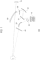
- FIG. 12 is a schematic diagram showing an image projecting device in the related art for projecting a plurality of images on one screen.
- the image projecting device in the related art includes an image irradiation unit 1B, a reflecting mirror 2B, a free-form surface mirror 3B, a light branching unit 4B, a free-form surface mirror 5B, and a windshield 6B.
- a part of light emitted from the image irradiation unit 1B is branched by the light branching unit 4B, reflected by the free-form surface mirror 5B, the free-form surface mirror 3B, and the windshield 6B to reach a viewpoint of the driver, and a virtual image 8B is formed in the distance.
- Another part of the light emitted from the image irradiation unit 1B is reflected by the reflecting mirror 2B, the free-form surface mirror 3B, and the windshield 6B to reach the viewpoint of the driver, and a virtual image 7B is formed in the near.
- the virtual image 8B is projected in the distance (about 15 m from the driver in FIG. 12 ) that is several degrees downward the horizontal direction, and it is possible to reduce the movement of the line of sight for the driver to visually recognize driving support information.
- the virtual image 7B is projected in the near further downward (about 3 m from the driver in FIG. 12 ), and the driver can visually recognize vehicle speed display or the like well by moving the line of sight.
- the vehicle per se and the image projecting device vibrate according to a traveling state and a road surface state while the vehicle is traveling, there is a problem in that imaging positions of the virtual images 7B and 8B are displaced due to the vibration and visibility is reduced.
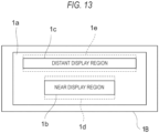
- FIG. 13 is a schematic diagram showing a display region displayed by the image irradiation unit 1B in the image projecting device of the related art.
- an entire display region 1a indicates the entire region in which an image can be displayed.
- the entire display region 1a is provided with a near display region 1b configured to display a near image formed in the near and a distant display region 1c configured to display a distant image formed in the distance.
- a near display region 1b configured to display a near image formed in the near
- a distant display region 1c configured to display a distant image formed in the distance.
- a method is considered in which a sensor configured to detect the vibration of the vehicle is provided in advance and an image display position in the image irradiation unit 1B is corrected according to a detection result of the sensor.
- the sensor detects the vibration of the vehicle, a vibration direction and a displacement amount are calculated, and the display positions of the near display region 1b and the distant display region 1c are changed within margin regions 1d and 1e, respectively. Accordingly, a displacement of the virtual images 7B and 8B due to the vibration is offset by a displacement in the margin regions 1d and 1e, and it is possible to prevent the changes in the imaging positions of the near image and the distant image.
- An object of the present disclosure is to provide an image projecting device capable of achieving space saving and an improvement in a degree of freedom in design while displaying instruments and projecting an auxiliary image as a virtual image.
- an object of the present disclosure is to provide an image projecting device and an image projecting method capable of improving a visibility of an image by preventing a fluctuation in an imaging position due to vibration of a vehicle while ensuring an effective image display area.
- An image projecting device of the present disclosure is an image projecting device for emitting a projection image on a display unit configured to display a virtual image
- the image projecting device including: an image irradiation unit configured to emit an image; a light branching unit configured to branch light for emitting the image into at least first image light and second image light; a first optical unit configured to emit, as the projection image, the first image light in a viewpoint direction, via the display unit; and a second optical unit configured to emit the second image light in the viewpoint direction, without passing through the display unit.
- the image emitted from the image irradiation unit is branched into the first image light and the second image light by the light branching unit, the first image light is emitted by the first optical unit via the display unit, and the second image light is emitted by the second optical unit without passing through the display unit. Accordingly, it is possible to achieve space saving and an improvement in a degree of freedom in design while displaying instruments with the second image light and projecting an auxiliary image as the projection image (virtual image) with the first image light.
- An image projecting device of the present disclosure is an image projecting device for emitting a projection image on a display unit configured to display a virtual image, the image projecting device including: an image irradiation unit configured to emit a first image; a first optical unit configured to emit, as first image light, the first image in a viewpoint direction, via the display unit; and a first optical drive unit configured to change an incident angle of the first image light to the display unit, based on vibration information.
- a correction amount of an incident angle of the first image light to the display unit is calculated based on the vibration information, and the first optical drive unit is controlled in accordance with the correction amount to correct an imaging position of the first image. Therefore, it is possible to prevent a fluctuation in the imaging position due to a vibration of the vehicle and improve visibility of the image while ensuring an effective image display area.
- An image projecting method of the present disclosure is an image projecting method for emitting a projection image on a display unit configured to display a virtual image, the image projecting method including: emitting a first image, as first image light, in a viewpoint direction, via the display unit; acquiring vibration information; and changing an incident angle of the first image light to the display unit, based on the vibration information to correct an imaging position of the first image.
- an image projecting device capable of achieving the space saving and the improvement in the degree of freedom in design while displaying the instruments and projecting the auxiliary image as the virtual image.
- an image projecting device and an image projecting method capable of improving the visibility of the image by preventing the fluctuation in the imaging position due to the vibration of the vehicle while ensuring an effective image display area.
- FIG. 1 is a schematic diagram showing a configuration of an image projecting device 100 according to the present embodiment.
- the image projecting device 100 includes an image irradiation unit 10, a light branching unit 20, a reflecting mirror 31, a free-form surface mirror 32, a free-form surface mirror 33, a direct display unit 40, and an external light cut filter 50, and is configured to project a virtual image 70 via a windshield (display unit) 60.
- the image projecting device 100 includes a control unit (not shown) that is connected to each unit to be able to communicate information and that is configured to control each unit.
- a configuration of the control unit is not limited, and examples thereof include a central processing unit (CPU) for performing information processing, a memory device, a recording medium, and an information communication device.
- the control unit is configured to control an operation of each unit according to a predetermined program, and configured to send information (image information) including an image to the image irradiation unit 10.
- the image irradiation unit 10 is a part configured to emit light including an image, based on image information from the control unit.
- a specific configuration of the image irradiation unit 10 is not limited, and examples thereof include a liquid crystal display device, an organic EL display device, and a combination of a laser light source and a light modulation element.
- the image irradiation unit 10 is configured to irradiate a light emitting diode (LED) with light from a back side of the liquid crystal display device.
- the image irradiation unit 10 includes a first region 11 and a second region 12 that are configured to display a first image and a second image, respectively.
- the light branching unit 20 is an optical member configured to branch the light of the image emitted from the image irradiation unit 10.
- the light branching unit 20 is configured to branch light into at least first image light that is the first image displayed in the first region 11, and second image light that is the second image displayed in the second region 12.
- a structure of the light branching unit 20 is not limited as long as the light branching unit 20 is an optical member that branches the light, and is, for example, a prism.
- a method in which an incident angle and a reflection angle of the light are made different by a reflecting mirror may be used.
- the light branching unit 20 is a prism, and the prism is arranged to overlap the second region of the image irradiation unit 10.
- the first image light emitted from the first region 11 reaches the reflecting mirror 31, and the second image light emitted from the second region 12 reaches the free-form surface mirror 33 along a path different from that of the first image light by the light branching unit 20.
- arranging the light branching unit 20 to overlap the image irradiation unit 10 means that a region where the light branching unit 20 is arranged overlaps an image display region of the image irradiation unit 10 in a plan view.
- a case where the light branching unit 20 and the image irradiation unit 10 are in contact with each other and a case where the light branching unit 20 and the image irradiation unit 10 are not in contact with each other are included in the overlapping arrangement.
- an optical member configured to transmit light or a holding member for maintaining the distance between the light branching unit 20 and the image irradiation unit 10 is interposed between the light branching unit 20 and the image irradiation unit 10 is also included in the overlapping arrangement.
- the reflecting mirror 31 is an optical member on which the first image light emitted from the image irradiation unit 10 is incident and which is configured to reflect the first image light toward a free-form surface mirror 32 direction.
- the reflecting mirror 31 is a flat mirror.
- the reflecting mirror 31 has an optical design necessary for projecting the first image light as the virtual image 70, and may be a concave mirror, a convex mirror, a free-form surface mirror, and the like, as necessary.
- the reflecting mirror 31 may be omitted, and the first image light from the image irradiation unit 10 may directly enter the free-form surface mirror 32.
- the free-form surface mirror 32 is a concave mirror on which the first image light reflected by the reflecting mirror 31 is incident, and which is configured to reflect the first image light toward a windshield 60 direction.
- a reflection surface of the free-form surface mirror 32 is designed such that a light diameter is enlarged toward a viewpoint direction of a driver.
- the enlargement of the light diameter in the viewpoint direction includes not only the case where the light diameter is enlarged uniformly after the reflection but also the case where the light diameter is enlarged after being reduced and imaged at an intermediate point.
- the free-form surface mirror 33 is an optical member on which the second image light is incident via the light branching unit 20, and which is configured to reflect the second image light toward a direct display unit 40 direction.
- the free-form surface mirror 33 corresponds to an enlarging optical unit configured to cause the reflected second image light to reach the direct display unit 40 while enlarging the light diameter thereof, and is configured to display the second image on the direct display unit 40 with an area larger than an area of a second region on the image irradiation unit 10.
- the direct display unit 40 is an optical member on which the second image light reflected by the free-form surface mirror 33 is incident, and which is configured to allows the driver to directly visually recognize the second image light.
- a configuration of the direct display unit 40 is not limited as long as the driver can visually recognize the second image light that reaches the direct display unit 40, and may be a plate glass, a retardation film, or a transmission screen that transmits visible light.
- the direct display unit 40 is a transmission screen
- the second image light emitted to a rear surface is diffused by the transmission screen, and thus the visibility can also be improved when visually recognizing through polarized glasses or from an oblique direction.
- a polarized light plane of the second image light and a fast axis of the retardation film are preferably different from each other by a predetermined angle (typically 45 degrees).
- a predetermined angle typically 45 degrees.
- the external light cut filter 50 is an optical member that is arranged on a path of the first image light between the image irradiation unit 10 and the windshield 60, and that has a wavelength characteristic of blocking infrared light and/or ultraviolet light and transmitting the visible light.
- the external light cut filter 50 is arranged between the windshield 60 and the free-form surface mirror 32, and an arrangement location of the external light cut filter 50 is not limited as long as external light incident on the image irradiation unit 10 can be cut.
- the external light cut filter 50 By arranging the external light cut filter 50, the infrared light and/or ultraviolet light included in the external light such as solar light incident from above the windshield 60 is blocked.
- the solar light reaches the image display region of the image irradiation unit 10 via the free-form surface mirror 32 and the reflecting mirror 31, it is possible to reduce a temperature rise of the image irradiation unit 10 and deterioration of a display surface.
- the external light cut filter 50 is configured to transmit the visible light
- the first image light favorably transmits the external light cut filter 50 and does not affect the projection of the virtual image 70.
- the windshield 60 is a member that is provided in front of a driver's seat of the vehicle and transmits the visible light.
- the windshield 60 is configured to reflect the first image light incident from the free-form surface mirror 32 on an inner surface of the vehicle toward the viewpoint direction, and is configured to transmit the light from the outside of the vehicle toward the viewpoint direction.
- the windshield 60 corresponds to a display unit of the present disclosure.
- the display unit is the windshield 60.
- a combiner may be provided as the display unit different from the windshield 60 to reflect light from the free-form surface mirror 32 toward the viewpoint direction.
- a position of the windshield 60 is not limited to the front of the vehicle.
- the windshield 60 may be arranged on a lateral side or a rear side of the vehicle as long as the windshield 60 projects an image to the viewpoint of a passenger.
- the virtual image 70 is an image displayed to be formed in the space in a case where the first image light reflected by the windshield 60 reaches the viewpoint (eye boxes) of the driver or the like.
- a position where the virtual image 70 is formed is determined by a spread angle when the light emitted from the image irradiation unit 10 travels in the viewpoint direction after being reflected by the reflecting mirror 31, the free-form surface mirror 32, and the windshield 60.
- a combination of the reflecting mirror 31, the free-form surface mirror 32, and the external light cut filter 50 corresponds to a first optical unit of the present disclosure.
- the image projecting device 100 is configured to emit the first image light, as the projection image, in the viewpoint direction via the windshield (display unit) 60.
- a combination of the light branching unit 20, the free-form surface mirror 33, and the direct display unit 40 corresponds to a second optical unit of the present disclosure.
- the image projecting device 100 is configured to emit the second image light in the viewpoint direction without passing through the windshield (display unit) 60.
- a convex lens or a concave lens may be arranged on the first optical unit or the second optical unit as necessary, and the light diameter may be enlarged or reduced.
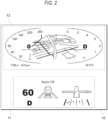
- FIG. 2 is a schematic diagram showing an image emitted from the image irradiation unit 10.
- the first image is displayed in the first region 11, and the second image is displayed in the second region 12.
- auxiliary information relating to driving such as a speed, a volume indicator, and a traveling direction guide, is displayed.
- a speedometer, a car navigation screen, and instruments such as driving mode information are displayed.
- the prism serving as the light branching unit 20 is arranged at a position overlapping the second region 12, and paths of the first image light from the first region 11 and the second image light from the second region 12 are branched.
- the first image displayed in the first region 11 reaches the viewpoint of the driver via the reflecting mirror 31, the free-form surface mirror 32, the external light cut filter 50, and the windshield 60.
- the driver visually recognizes that the virtual image 70 is displayed as the projection image at a position farther than the windshield 60.
- the second image displayed in the second region 12 reaches the viewpoint of the driver via the light branching unit 20, the free-form surface mirror 33, and the direct display unit 40. Accordingly, the driver visually recognizes that the second image is displayed on the direct display unit 40.
- FIG. 3 is a graph showing a relation between the incident angle and the reflectivity of light to the windshield 60.
- a horizontal axis represents the incident angle of the light to the windshield 60
- a vertical axis represents a relative reflectivity when the incident angle of 90 degrees is 100%.
- a solid line and a broken line in the drawing indicate theoretical values of P polarized light and S polarized light, respectively
- white circles and black circles indicate measured values of the P polarized light and the S polarized light, respectively.
- the free-form surface mirror 32 since a reflectivity of the P polarized light significantly decreases in the vicinity of an incident angle of 60 degrees to the windshield 60, it is preferable to arrange the free-form surface mirror 32 at a position where the incident angle is 55 degrees or less or 65 degrees or more.
- the free-form surface mirror 32 is arranged such that the incident angle of the first image light to the windshield 60 is 55 degrees or less or 65 degrees or more, a ratio of reflected light including the P polarized light increases as shown in FIG. 3 . Accordingly, even when the driver uses the polarized glasses and the S polarized light is cut by the polarized glasses, the driver can visually recognize the virtual image 70 projected with the first image light.
- the image emitted from the image irradiation unit 10 is branched into the first image light and the second image light by the light branching unit 20, the first image light is emitted by the first optical unit via the windshield 60, and the second image light is emitted by the second optical unit without passing through the windshield 60.
- the first image and the second image are displayed by one image irradiation unit 10, so that space saving and an improvement in a degree of freedom in design can be achieved.
- the second image light is directly displayed while the virtual image 70 is projected with the first image light, it is possible to achieve the space saving and the improvement in the degree of freedom in design while displaying the instruments with the second image light and projecting an auxiliary image as the projection image (virtual image) with the first image light.
- the light branching unit 20 when the light branching unit 20 is a prism, optical design when partially covering the image irradiation unit 10 and branching a part of the light is facilitated.
- an area ratio of the second region 12 to the image irradiation unit 10 is greater than that of the first region 11. Therefore, it is more advantageous for downsizing when the light branching unit 20 is a prism than when the light branching unit 20 is a reflecting mirror.
- a chromatic aberration occurs in a lens or a prism
- an angle of the prism is a parameter in the prism
- regularity of the chromatic aberration is high, and by performing color correction in advance in image processing, aberration correction becomes easy.
- FIG. 4 is a schematic diagram showing a configuration of an image projecting device 110 according to the present embodiment.
- the present embodiment is different from the first embodiment in that the light branching unit 20 is included in the first optical unit.
- the image projecting device 110 includes the image irradiation unit 10, the light branching unit 20, the reflecting mirror 31, the free-form surface mirror 32, the free-form surface mirror 33, and the direct display unit 40, and is configured to project the virtual image 70 via the windshield (display unit) 60.
- the light branching unit 20 is arranged between the image irradiation unit 10 and the reflecting mirror 31, the light branching unit 20 is formed of a prism, and a material forming the prism contains an infrared light absorbing material.
- a combination of the light branching unit 20, the reflecting mirror 31, and the free-form surface mirror 32 corresponds to a first optical unit of the present disclosure.
- the image projecting device 110 is configured to emit first image light, as a projection image, in a viewpoint direction via the windshield (display unit) 60.
- a combination of the free-form surface mirror 33 and the direct display unit 40 corresponds to a second optical unit of the present disclosure.
- the image projecting device 110 is configured to emit the second image light in the viewpoint direction without passing through the windshield (display unit) 60.
- the prism serving as the light branching unit 20 is arranged at a position overlapping the first region 11, and is configured to branch paths of the first image light from the first region 11 and the second image light from the second region 12.
- the first image displayed in the first region 11 reaches a viewpoint of a driver via the light branching unit 20, the reflecting mirror 31, the free-form surface mirror 32, and the windshield 60.
- the driver visually recognizes that the virtual image 70 is displayed as the projection image at a position farther than the windshield 60.
- the second image displayed in the second region 12 reaches the viewpoint of the driver via the free-form surface mirror 33 and the direct display unit 40. Accordingly, the driver visually recognizes that the second image is displayed on the direct display unit 40.
- the prism is implemented by using a resin or glass having a high refractive index that is configured to transmit visible light as a base material, and the base material contains an infrared light absorbing material that is configured to absorb infrared light.
- the light branching unit 20 may contain an ultraviolet light absorbing material. As a result, it is possible to block infrared light and/or ultraviolet light included in external light such as solar light incident from above the windshield 60 at the light branching unit 20 arranged between the image irradiation unit 10 and the windshield 60, and to reduce a temperature rise of the image irradiation unit 10.
- the image emitted from the image irradiation unit 10 is branched into the first image light and the second image light by the light branching unit 20, the first image light is emitted via the windshield 60 by the first optical unit, and the second image light is emitted by the second optical unit without passing through the windshield 60. Accordingly, it is possible to achieve space saving and an improvement in a degree of freedom in design while displaying instruments with the second image light and projecting an auxiliary image as the projection image (virtual image) with the first image light.
- FIG. 5 is a schematic diagram showing a configuration of an image projecting device 120 according to the present embodiment.
- the image projecting device 120 of the present embodiment is different from the first embodiment in that a plurality of light branching units 20 are provided.
- the image projecting device 120 includes the image irradiation unit 10, light branching units 20a and 20b, the reflecting mirror 31, the free-form surface mirror 32, the free-form surface mirror 33, a reflecting mirror 34, a free-form surface mirror 35, the direct display unit 40, and the external light cut filter 50, and is configured to project virtual images 70a and 70b via the windshield (display unit) 60.
- the image irradiation unit 10 in the display region of the image irradiation unit 10, a first image is displayed in the first region 11, a second image is displayed in the second region 12, and a third image is displayed in a third region.
- the light branching units 20a and 20b are optical members configured to branch light of an image emitted from the image irradiation unit 10.
- the light branching units 20a and 20b are prisms, and the respective prisms are arranged to overlap the second region 12 and the third region of the image irradiation unit 10.
- the reflecting mirror 34 is an optical member on which third image light emitted from the image irradiation unit 10 is incident and which is configured to reflect the third image light toward a free-form surface mirror 35 direction.
- the free-form surface mirror 35 is a concave mirror on which the third image light reflected by the reflecting mirror 34 is incident, and which is configured to reflect the third image light toward a windshield 60 direction.
- a reflection surface of the free-form surface mirror 35 is designed such that a light diameter is enlarged toward a viewpoint direction of a driver.
- a combination of the reflecting mirror 31, the free-form surface mirror 32, and the external light cut filter 50 corresponds to a first optical unit of the present disclosure.
- the image projecting device 120 is configured to emit first image light, as a projection image, in the viewpoint direction via the windshield (display unit) 60.
- a combination of the light branching unit 20a, the free-form surface mirror 33, and the direct display unit 40 corresponds to a second optical unit of the present disclosure.
- the image projecting device 120 is configured to emit the second image light in the viewpoint direction without passing through the windshield (display unit) 60.
- a combination of the light branching unit 20b, the reflecting mirror 31, the free-form surface mirror 32, and the external light cut filter 50 corresponds to a third optical unit of the present disclosure.
- the image projecting device 120 is configured to emit the third image light, as a projection image, in the viewpoint direction through the windshield (display unit) 60.
- FIG. 5 shows an example in which the free-form surface mirror 32 and the free-form surface mirror 35 are formed separately, a free-form surface mirror in which two free-form surfaces are integrally formed may be arranged.
- the prisms serving as the light branching units 20a and 20b are arranged at positions overlapping the second region 12 and the third region, respectively, and are configured to branch paths of the first image light from the first region 11, the second image light from the second region 12, and the third image light from the third region.
- the first image displayed in the first region 11 reaches the viewpoint of the driver via the reflecting mirror 31, the free-form surface mirror 32, the external light cut filter 50, and the windshield 60.
- the second image displayed in the second region 12 reaches the viewpoint of the driver via the light branching unit 20a, the free-form surface mirror 33, and the direct display unit 40. Accordingly, the driver visually recognizes that the second image is displayed on the direct display unit 40.
- the third image displayed in the third region reaches the viewpoint of the driver through the light branching unit 20b, the reflecting mirror 34, the free-form surface mirror 35, the external light cut filter 50, and the windshield 60.
- the driver visually recognizes that the virtual images 70a and 70b are displayed as the projection images at positions farther than the windshield 60.
- the image emitted from the image irradiation unit 10 is branched into the first image light, the second image light, and the third image light by the light branching units 20a and 20b, the first image light and the third image light are emitted via the windshield 60 by the first optical unit and the third optical unit, respectively, and the second image light is emitted by the second optical unit without passing through the windshield 60. Accordingly, it is possible to achieve space saving and an improvement in a degree of freedom in design while displaying instruments with the second image light and projecting auxiliary images as the projection images (virtual images) with the first image light and the third image light.
- FIG. 7 is a block diagram showing a configuration of an image projecting device 100B according to the present embodiment.
- the image projecting device 100B includes an image irradiation unit 10B, a light branching unit 20B, a first optical unit 30B, a second optical unit 40B, a vibration detection unit 50B, a correction control unit 60B, and an optical drive unit 70B.
- the light projected from the image projecting device 100B is emitted to a viewpoint position of a driver via a windshield (display unit) (not shown).
- the image irradiation unit 10B includes a distant display region 13B and a near display region 12B that is configured to display a distant image and a near image, respectively.
- the light branching unit 20B is an optical member configured to branch light of an image emitted from the image irradiation unit 10B.
- the light branching unit 20B is configured to branch light into at least first image light that is a first image displayed in the distant display region 13B, and second image light that is a second image displayed in the near display region 12B.
- the light branching unit 20B is a prism, and the prism is arranged to overlap the distant display region 13B of the image irradiation unit 10B.
- the first image light emitted from the distant display region 13B is reflected by a free-form surface mirror 41 along a path different from that of the second image light by the light branching unit 20B, and reaches the free-form surface mirror 32.
- the second image light emitted from the near display region 12B is reflected by a reflecting mirror 31B and reaches the free-form surface mirror 32.
- the first optical unit 30B is a combination of optical elements configured to set the distant image displayed in the distant display region 13B as the first image light and configured to emit the first image light in the viewpoint direction via the display unit.
- An optical configuration of the first optical unit 30B is not limited, and a plurality of reflecting mirrors, lenses, prisms, and the like may be combined.
- the second optical unit 40B is a combination of optical elements configured to set the near image displayed in the near display region 12B as the second image light and configured to emit the second image light in the viewpoint direction via the display unit.
- An optical configuration of the second optical unit 40B is not limited, and a plurality of reflecting mirrors, lenses, prisms, and the like may be combined.
- the vibration detection unit 50B is a part configured to acquire vibration information by detecting vibration during traveling or the like of a vehicle on which the image projecting device 100B is mounted.
- a specific configuration of the vibration detection unit 50B is not limited, and the vibration detection unit 50B may be an acceleration sensor such as a gyro sensor.
- the image projecting device 100B includes the vibration detection unit 50B inside the image projecting device 100B.
- the image projecting device 100B may be configured to acquire the vibration information by acquiring the vibration information by the vibration detection unit 50B separately provided outside the image projecting device 100B, and configured to transmit the vibration information to a control unit of the image projecting device 100B using an information communication unit.
- the correction control unit 60B is configured to calculate a correction amount of an incident angle of the first image light to the display unit from the first optical unit 30B, based on the vibration information acquired by the vibration detection unit 50B, and is configured to control the optical drive unit 70B according to the correction amount to correct an imaging position of the first image.
- the correction control unit 60B is realized by a program executed by the control unit, and executes each step according to a predetermined procedure.
- the image projecting device 100 includes the correction control unit 60B inside the image projecting device 100.
- the correction control unit 60B separately provided outside the image projecting device 100B may be configured to calculate the correction amount based on the vibration information, and the correction amount may be transmitted using the information communication unit.
- a control signal for the optical drive unit 70B may be generated based on the correction amount calculated externally, and driving of the optical drive unit 70B may be controlled using the information communication unit.
- the optical drive unit 70B is configured to change the incident angle of the first image light to the display unit by changing a light path of the first optical unit 30B.
- a configuration of the optical drive unit 70B is not limited, and may be, for example, a motor device configured to change an angle of the first optical unit 30B or the light branching unit 20B, an optical element configured to electrically control a traveling direction of light, or the like.
- the optical drive unit 70B corresponds to a first optical drive unit of the present disclosure. In a case where the optical drive unit 70B is a motor device, the optical drive unit 70B is preferably a stepping motor configured to precisely control a rotation angle.
- FIG. 8 is a schematic diagram showing a configuration of the image projecting device 100B according to the present embodiment.
- the image projecting device 100B includes the image irradiation unit 10B, the light branching unit 20B, the vibration detection unit 50B, the correction control unit 60B, the optical drive unit 70B, the reflecting mirror 31B, the free-form surface mirror 32, the free-form surface mirror 41, and an external light cut filter 80.
- a combination of the free-form surface mirror 41 and the free-form surface mirror 32 corresponds to the first optical unit 30B of the present disclosure.
- a combination of the reflecting mirror 31, the free-form surface mirror 32, and the free-form surface mirror 41 corresponds to the second optical unit 40B of the present disclosure.
- a part of the light emitted from the image irradiation unit 10B emits the first image light in the viewpoint direction via the first optical unit 30B and the windshield (display unit).
- another part of the light emitted from the image irradiation unit 10B emits the second image light in the viewpoint direction via the second optical unit 40B and the windshield (display unit).
- a convex lens or a concave lens may be arranged on the first optical unit 30B or the second optical unit 40B as necessary, and the light diameter may be enlarged or reduced.
- the arrangement and orientation of the light branching unit 20B, the reflecting mirror 31B, the free-form surface mirror 32, the free-form surface mirror 41, and the external light cut filter 80 are not limited to those shown in FIG. 8 .
- the reflecting mirror 31B is an optical member on which the second image light emitted from the image irradiation unit 10B is incident, and which is configured to reflect the first image light toward the free-form surface mirror 32 direction.
- the reflecting mirror 31B is a convex mirror.
- the reflecting mirror 31B may be a concave mirror, a plane mirror, a free-form surface mirror, or the like, as necessary.
- the free-form surface mirror 32 is a concave mirror on which the second image light reflected by the reflecting mirror 31B is incident, and which is configured to reflect the second image light toward a windshield direction.
- a reflection surface of the free-form surface mirror 32 is designed such that the light diameter is enlarged toward the viewpoint direction of the driver in order to project the virtual image via the windshield.
- the free-form surface mirror 41 is an optical member on which the first image light is incident via the light branching unit 20B, and which is configured to reflect the first image light toward the free-form surface mirror 32 direction.
- a reflection surface of the free-form surface mirror 41 is designed such that the light diameter is enlarged toward the viewpoint direction of the driver in order to project the virtual image via the windshield.
- the external light cut filter 80 is an optical member that is arranged on a path of the first image light between the image irradiation unit 10B and the windshield, and that has a wavelength characteristic of blocking infrared light and/or ultraviolet light and transmitting visible light.
- the external light cut filter 80 is arranged between the windshield and the free-form surface mirror 32, and an arrangement location of the external light cut filter 80 is not limited as long as external light incident on the image irradiation unit 10B can be cut.
- the external light cut filter 80 By arranging the external light cut filter 80, the infrared light and/or ultraviolet light included in the external light such as solar light incident from above the windshield is blocked.
- the solar light reaches an image display region of the image irradiation unit 10B via the free-form surface mirror 32, the reflecting mirror 31B, and the free-form surface mirror 41, it is possible to reduce a temperature rise of the image irradiation unit 10B and deterioration of a display surface.
- the external light cut filter 80 is configured to transmit the visible light
- the first image light favorably transmits the external light cut filter 80 and does not affect the projection of the virtual image.
- the windshield is configured to reflect the first image light and the second image light incident from the free-form surface mirror 32 on an inner surface of the vehicle toward the viewpoint direction, and is configured to transmit the light from the outside of the vehicle toward the viewpoint direction.
- the windshield corresponds to a display unit of the present disclosure.
- the virtual image is an image displayed to be formed in the space when the first image light and the second image light reflected by the windshield reaches the viewpoint (eye boxes) of the driver or the like.
- a position where the virtual image is formed is determined by a spread angle when the light emitted from the image irradiation unit 10B travels in the viewpoint direction after being reflected by the reflecting mirror 31B, the free-form surface mirror 32, the free-form surface mirror 41, and the windshield.
- the optical drive unit 70B is a stepping motor, and is configured to change the angle of the light branching unit 20B.
- the correction control unit 60B is configured to calculate the correction amount based on the vibration information acquired by the vibration detection unit 50B, and is configured to send the control signal to the optical drive unit 70B.
- the optical drive unit 70B is driven according to the control signal, the light branching unit 20B is rotated about a direction perpendicular to the paper surface as a rotation axis, and an angle relative to the image irradiation unit 10B is changed. Accordingly, the light path of the first image light after passing through the light branching unit 20B is changed, and an imaging position of the distant image moves in the vertical direction of the paper surface.
- FIG. 9 is a schematic diagram showing a display region of the image emitted from the image irradiation unit 10B in the image projecting device 100B according to the present embodiment.
- An entire display region 11B is the entire region in which the image of the image irradiation unit 10B is displayed.
- a part of the entire display region 11B is the near display region 12B, and the other part is the distant display region 13B.
- the first image is displayed in the distant display region 13B, and the second image is displayed in the near display region 12B.
- the second image displayed in the near display region 12B includes, for example, a speed indicator, a sound volume indicator, and a traveling direction guide.
- the first image displayed in the distant display region 13B includes auxiliary information relating to driving, such as an alert image and emergency information.
- the prism serving as the light branching unit 20B is arranged at a position overlapping the distant display region 13B, and is configured to branch paths of the first image light from the distant display region 13B and the second image light from the near display region 12B.
- the first image displayed in the distant display region 13B reaches the viewpoint of the driver via the light branching unit 20B, the free-form surface mirror 41, the free-form surface mirror 32, the external light cut filter 80, and the windshield.
- the second image displayed in the near display region 12B reaches the viewpoint of the driver via the reflecting mirror 31B, the free-form surface mirror 32, the external light cut filter 80, and the windshield.
- the light diameters of the first image light and the second image light are enlarged by the first optical unit 30B and the second optical unit 40B, respectively, and the first image light and the second image light reach the viewpoint, and thus the driver visually recognizes that the virtual images of the first image and the second image light by the first image light and the second image light are formed at a predetermined distance.
- the imaging position of the virtual image is such that the first image is farther from the viewpoint position than the second image.
- FIG. 10 is a flowchart showing steps of an image projecting method according to the present embodiment.
- a near image (second image) is displayed in the near display region 12B of the image irradiation unit 10B, and a distant image (first image) is displayed in the distant display region 13B, and the near image and the distant image are emitted as the first image light and the second image light, respectively.
- the emission and the imaging of the virtual image of the first image light and the second image light are the same as those described above.
- the process proceeds to step S2.
- a vibration detection step of step S2 vibration of the vehicle is detected by the vibration detection unit 50B to acquire the vibration information, and the acquired vibration information is sent to the correction control unit 60B.
- the vibration detection unit 50B is an acceleration sensor
- information on an acceleration detected by the acceleration sensor is sent as the vibration information to the correction control unit 60B.
- the information on the acceleration detected by the acceleration sensor is integrated within a predetermined period, a change amount of a speed and a position is calculated, and the change amount of the position is sent to the correction control unit 60B as the vibration information.
- the process proceeds to step S3.
- the correction control unit 60B generates the control signal for the optical drive unit 70B, based on the acquired vibration information.
- the vibration information is the information on the acceleration
- the change amount of the speed and the position is calculated by integrating within a predetermined period, and the change amount of the position is converted into a change amount in the incident angle on the windshield.
- a rotation angle of the light path in the first optical unit 30B is calculated from the change amount of the incident angle on the windshield, and the control signal is generated to change the light path of the first optical unit 30B in a direction opposite to the rotation angle.
- the rotation angle is obtained in consideration of a refractive index of the light branching unit 20B and the incident angle of the first image light.
- the correction control unit 60B sends the control signal to the optical drive unit 70B, and the process proceeds to step S4.
- step S4 the optical drive unit 70B is driven based on the control signal generated in the correction amount calculation step, to change the light path of the first optical unit 30B.
- the optical drive unit 70B is provided in the light branching unit 20B
- the light branching unit 20B is rotated to change the incident angle to the free-form surface mirror 41.
- the imaging position of the virtual image is controlled in a direction opposite to the vibration of the vehicle, and a positional deviation from a background due to the vibration of the vehicle is canceled out, thereby improving visibility.
- step S5 it is determined whether the image projecting method is ended, and when the process does not end, the process proceeds to step S1, and feedback control of vibration correction is continued.
- the control is ended after leaving a loop of the feedback control.
- the correction amount calculation step and the correction control step are described as separate steps, and the correction amount may also be calculated in the correction control step.
- the first optical unit 30B is controlled, based on the vibration information, to correct the imaging position of the first image. Since the fluctuation of the imaging position due to the vibration is optically corrected by the feedback control, it is not necessary to provide a margin region in the entire display region 11B as shown in FIG. 9 . Accordingly, an effective image display area is secured, the areas of the near display region 12B and the distant display region 13B are increased, and the large first image and second image can be projected. Accordingly, it is possible to improve the visibility of the image by preventing the fluctuation of the imaging position due to the vibration of the vehicle.
- the present embodiment shows an example in which the distant image is emitted as the first image light and the near image is emitted as the second image light, the first image light may be formed as the near image at a nearby position, and the second image light may be formed as the distant image at a far position.
- the distant image a distance from the viewpoint position of the driver to the imaging position is long, and the deviation from the background caused by a shake of the imaging position due to the vibration tends to be large. Accordingly, the effect of preventing positional deviation with the background to improve the visibility can be enhanced by imaging the first image light at a far distance as the distant image and correcting the imaging position based on the vibration information.
- the light branching unit 20 is a prism
- the prism is smaller and lighter than the reflecting mirror 31B, the free-form surface mirror 32, the free-form surface mirror 41, and the like, a torque when a rotation operation is performed by the optical drive unit 70B is reduced, and it is possible to reduce an output power and a size of the optical drive unit 70B.
- the prism is small in size and light in weight, it is possible to improve an accuracy at the time of the rotation operation and increase a rotation speed at the time of correction.
- the correction amount of the incident angle of the first image light to the windshield is calculated based on the vibration information, and the optical drive unit 70B is controlled according to the correction amount to correct the imaging position of the first image. Accordingly, it is possible to improve visibility of the image by preventing the fluctuation of the imaging position due to the vibration of the vehicle while ensuring the effective image display area.
- FIG. 11 is a schematic diagram showing the configuration of the image projecting device 110B according to the present embodiment.
- the image projecting device 110B includes the image irradiation unit 10B, light branching units 20aB and 20bB, the reflecting mirror 31B, the free-form surface mirror 32, the free-form surface mirror 41, the vibration detection unit 50B, the correction control unit 60B, optical drive units 70aB and 70bB, and the external light cut filter 80.
- the present embodiment is different from the first embodiment in that the light branching units 20aB and 20bB and the optical drive units 70aB and 70bB are provided, and both the first optical unit 30B and the second optical unit 40B perform vibration correction.
- the light branching unit 20aB is arranged at a position overlapping the distant display region 13B, and first image light from the distant display region 13B is branched toward a free-form surface mirror 41 direction.
- the light branching unit 20aB corresponds to a first light branching unit of the present disclosure.
- the light branching unit 20bB is arranged at a position overlapping the near display region 12B, and second image light from the near display region 12B is branched in a reflecting mirror 31B direction.
- the light branching unit 20bB corresponds to a second light branching unit of the present disclosure.
- a first image displayed in the distant display region 13B reaches a viewpoint of a driver via the light branching unit 20aB, the free-form surface mirror 41, the free-form surface mirror 32, the external light cut filter 80, and a windshield.
- a second image displayed in the near display region 12B reaches the viewpoint of the driver through the light branching unit 20bB, the reflecting mirror 31B, the free-form surface mirror 32, the external light cut filter 80, and the windshield.
- the optical drive units 70aB and 70bB are provided in the light branching units 20aB and 20bB, respectively, and are configured to change a relative angle to the image irradiation unit 10B, and correspond to a first optical drive unit and a second optical drive unit of the present disclosure, respectively.
- the vibration detection unit 50B and the correction control unit 60B are configured to detect a vibration of a vehicle, configured to separately control the optical drive units 70aB and 70bB based on vibration information, and configured to correct fluctuations in imaging positions of the first image and the second image due to the vibration.
- correction amounts of incident angles of the first image light and the second image light to the windshield are calculated based on the vibration information, and the optical drive units 70aB and 70bB are controlled according to the correction amount to correct the imaging positions of the first image and the second image. Accordingly, it is possible to improve visibility of the image by preventing the fluctuation of the imaging position due to the vibration of the vehicle while ensuring the effective image display area.
- the light emitted from the image irradiation unit 10B is branched using the light branching unit 20B, and projected as the distant image and the near image at different distances to form the virtual image.
- one virtual image may be formed by the first optical unit 30B without using the light branching unit 20B and the second optical unit 40B, using one image displayed by the image irradiation unit 10B.
- the optical drive unit 70B may be provided on the free-form surface mirror 41 to change a relative angle of the free-form surface mirror 41 to the image irradiation unit 10B.
- the optical drive unit 70B is controlled in the same manner as in the fourth embodiment, vibration information of a vehicle is acquired by the vibration detection unit 50B, a correction amount is calculated by the correction control unit 60B based on the vibration information, and a control signal for controlling driving of the optical drive unit 70B is generated.
- a correction amount of an incident angle of first image light to a windshield (display unit) is calculated based on the vibration information, and the optical drive units 70B is controlled according to the correction amount to correct imaging positions of the first image and the second image. Accordingly, it is possible to improve visibility of the image by preventing the fluctuation of the imaging position due to the vibration of the vehicle while ensuring the effective image display area.
Landscapes
- Physics & Mathematics (AREA)
- Engineering & Computer Science (AREA)
- General Physics & Mathematics (AREA)
- Optics & Photonics (AREA)
- Chemical & Material Sciences (AREA)
- Combustion & Propulsion (AREA)
- Transportation (AREA)
- Mechanical Engineering (AREA)
- Instrument Panels (AREA)
Abstract
Description
- The present disclosure relates to an image projecting device, and more particularly, to an image projecting device and an image projecting method configured to emit a projection image on a display unit for displaying a virtual image.
- In the related art, an instrument panel for lighting and displaying an icon is used as a device for displaying various kinds of information in a vehicle. Due to an increase in an amount of information to be displayed, it has also been proposed to embed an image display device in the instrument panel or to form the entire instrument panel with the image display device.
- Since the instrument panel is located below a windshield of the vehicle, for a driver to visually recognize the information displayed on the instrument panel, it is necessary to move the line of sight downward while driving, which is undesirable. There has also been proposed a head up display (hereinafter, referred to as HUD) configured to project an image onto the windshield so that the driver can read information when visually recognizing the front of the vehicle (for example, see
Patent Literatures 1 and 2). -
- Patent Literature 1:
JP2019-119248A - Patent Literature 2:
JP2019-119262A -
FIGS. 6A, 6B , and6C are schematic diagrams showing an information presentation method using aHUD device 1 proposed in the related art.FIG. 6A shows an arrangement of devices inside the vehicle.FIG. 6B shows aninstrument image 2a displayed on ameter unit 2.FIG. 6C shows anauxiliary image 3a projected as avirtual image 3. In the information presentation method in the related art, themeter unit 2 is installed in the vehicle separately from theHUD device 1, and thevirtual image 3 is projected from theHUD device 1 via awindshield 4. Here, instruments defined by the law are displayed, as aninstrument image 2a, in themeter unit 2. Theauxiliary image 3a supporting driving is projected as thevirtual image 3. In recent years, there is a case where the design of an instrument is improved by using a liquid crystal display device or the like as themeter unit 2. - As shown in
FIGS. 6A to 6C , since thevirtual image 3 is projected several degrees (4 degrees inFIG. 6A ) downward from the horizontal direction while the vehicle is traveling, it is possible to reduce movement of the line of sight for thedriver 5 to visually recognize supplementary information. By moving the line of sight further downward (20 degrees inFIG. 6A ), thedriver 5 can visually recognize the instruments displayed on themeter unit 2 well. However, in the related art, since it is necessary to arrange theHUD device 1 and themeter unit 2 separately in an instrument panel of the vehicle, it is difficult to achieve space saving. In addition, since a position where themeter unit 2 is installed is inevitably determined at a position where thedriver 5 can visually recognize themeter unit 2 well, there is a problem that a degree of freedom in design when theHUD device 1 is arranged is low. - In order to present more information, it is also proposed to project a plurality of images on the windshield using a driving support HUD device. However, in order to project and form the plurality of images as virtual images at different distances, it is necessary to provide a plurality of image irradiation units and projection optical systems, and there is a problem in that the degree of freedom in design is low in order to house the plurality of image irradiation units and projection optical systems in the instrument panel. Therefore, the applicant of the present application has proposed an image projecting device in which a plurality of images are displayed in one image irradiation unit and a light path of each image is branched by a light branching unit such as a prism, to achieve space saving.
-
FIG. 12 is a schematic diagram showing an image projecting device in the related art for projecting a plurality of images on one screen. As shown inFIG. 12 , the image projecting device in the related art includes animage irradiation unit 1B, a reflectingmirror 2B, a free-form surface mirror 3B, alight branching unit 4B, a free-form surface mirror 5B, and awindshield 6B. In such an image projecting device, a part of light emitted from theimage irradiation unit 1B is branched by thelight branching unit 4B, reflected by the free-form surface mirror 5B, the free-form surface mirror 3B, and thewindshield 6B to reach a viewpoint of the driver, and avirtual image 8B is formed in the distance. Another part of the light emitted from theimage irradiation unit 1B is reflected by the reflectingmirror 2B, the free-form surface mirror 3B, and thewindshield 6B to reach the viewpoint of the driver, and avirtual image 7B is formed in the near. - In the image projecting device of the related art, the
virtual image 8B is projected in the distance (about 15 m from the driver inFIG. 12 ) that is several degrees downward the horizontal direction, and it is possible to reduce the movement of the line of sight for the driver to visually recognize driving support information. Thevirtual image 7B is projected in the near further downward (about 3 m from the driver inFIG. 12 ), and the driver can visually recognize vehicle speed display or the like well by moving the line of sight. However, since the vehicle per se and the image projecting device vibrate according to a traveling state and a road surface state while the vehicle is traveling, there is a problem in that imaging positions of thevirtual images -
FIG. 13 is a schematic diagram showing a display region displayed by theimage irradiation unit 1B in the image projecting device of the related art. In theimage irradiation unit 1B, anentire display region 1a indicates the entire region in which an image can be displayed. Theentire display region 1a is provided with anear display region 1b configured to display a near image formed in the near and adistant display region 1c configured to display a distant image formed in the distance. In the image projecting device shown inFIG. 12 , light for irradiating the near image displayed in thenear display region 1b is formed as thevirtual image 7B in the near via the reflectingmirror 2B, and light for irradiating the distant image displayed in thedistant display region 1c is formed as thevirtual image 8B in the distance via thelight branching unit 4B. However, since the vehicle and the image projecting device vibrate when the vehicle is traveling, the imaging positions of thevirtual images - In order to prevent changes in the imaging positions of the
virtual images image irradiation unit 1B is corrected according to a detection result of the sensor. When the sensor detects the vibration of the vehicle, a vibration direction and a displacement amount are calculated, and the display positions of thenear display region 1b and thedistant display region 1c are changed withinmargin regions virtual images margin regions - However, in a method of changing the display positions of the
near display region 1b and thedistant display region 1c in themargin regions margin regions entire display region 1a. This means that, for example, when a displacement amount of about 15% is secured above and below thenear display region 1b and thedistant display region 1c as shown inFIG. 13 , a size of the image that can be displayed is reduced by 30%. Accordingly, sizes of the images that can be formed as thevirtual images virtual images - An object of the present disclosure is to provide an image projecting device capable of achieving space saving and an improvement in a degree of freedom in design while displaying instruments and projecting an auxiliary image as a virtual image.
- Further, an object of the present disclosure is to provide an image projecting device and an image projecting method capable of improving a visibility of an image by preventing a fluctuation in an imaging position due to vibration of a vehicle while ensuring an effective image display area.
- An image projecting device of the present disclosure is an image projecting device for emitting a projection image on a display unit configured to display a virtual image, the image projecting device including: an image irradiation unit configured to emit an image; a light branching unit configured to branch light for emitting the image into at least first image light and second image light; a first optical unit configured to emit, as the projection image, the first image light in a viewpoint direction, via the display unit; and a second optical unit configured to emit the second image light in the viewpoint direction, without passing through the display unit.
- In the image projecting device of the present disclosure, the image emitted from the image irradiation unit is branched into the first image light and the second image light by the light branching unit, the first image light is emitted by the first optical unit via the display unit, and the second image light is emitted by the second optical unit without passing through the display unit. Accordingly, it is possible to achieve space saving and an improvement in a degree of freedom in design while displaying instruments with the second image light and projecting an auxiliary image as the projection image (virtual image) with the first image light.
- An image projecting device of the present disclosure is an image projecting device for emitting a projection image on a display unit configured to display a virtual image, the image projecting device including: an image irradiation unit configured to emit a first image; a first optical unit configured to emit, as first image light, the first image in a viewpoint direction, via the display unit; and a first optical drive unit configured to change an incident angle of the first image light to the display unit, based on vibration information.
- In the image projecting device according to the present disclosure, a correction amount of an incident angle of the first image light to the display unit is calculated based on the vibration information, and the first optical drive unit is controlled in accordance with the correction amount to correct an imaging position of the first image. Therefore, it is possible to prevent a fluctuation in the imaging position due to a vibration of the vehicle and improve visibility of the image while ensuring an effective image display area.
- An image projecting method of the present disclosure is an image projecting method for emitting a projection image on a display unit configured to display a virtual image, the image projecting method including: emitting a first image, as first image light, in a viewpoint direction, via the display unit; acquiring vibration information; and changing an incident angle of the first image light to the display unit, based on the vibration information to correct an imaging position of the first image.
- According to the present disclosure, it is possible to provide an image projecting device capable of achieving the space saving and the improvement in the degree of freedom in design while displaying the instruments and projecting the auxiliary image as the virtual image.
- In the present disclosure, it is possible to provide an image projecting device and an image projecting method capable of improving the visibility of the image by preventing the fluctuation in the imaging position due to the vibration of the vehicle while ensuring an effective image display area.
-
- [
FIG. 1] FIG. 1 is a schematic diagram showing a configuration of animage projecting device 100 according to a first embodiment. - [
FIG. 2] FIG. 2 is a schematic diagram showing an image emitted from theimage irradiation unit 10. - [
FIG. 3] FIG. 3 is a graph showing a relation between an incident angle and a reflectivity of light to awindshield 60. - [
FIG. 4] FIG. 4 is a schematic diagram showing a configuration of animage projecting device 110 according to a second embodiment. - [
FIG. 5] FIG. 5 is a schematic diagram showing a configuration of animage projecting device 120 according to a third embodiment. - [
FIG. 6A] FIG. 6A is a schematic diagram showing an information presentation method using aHUD device 1 proposed in the related art and shows an arrangement of devices inside a vehicle. - [
FIG. 6B] FIG. 6B is a schematic diagram showing the information presentation method using theHUD device 1 proposed in the related art and shows aninstrument image 2a displayed on ameter unit 2. - [
FIG. 6C] FIG. 6C is a schematic diagram showing the information presentation method using theHUD device 1 proposed in the related art and shows anauxiliary image 3a projected as avirtual image 3. - [
FIG. 7] FIG. 7 is a block diagram showing a configuration of animage projecting device 100B according to a fourth embodiment. - [
FIG. 8] FIG. 8 is a schematic diagram showing a configuration of theimage projecting device 100B according to the fourth embodiment. - [
FIG. 9] FIG. 9 is a schematic diagram showing a display region of an image emitted from animage irradiation unit 10B in theimage projecting device 100B according to the fourth embodiment. - [
FIG. 10] FIG. 10 is a flowchart showing steps of an image projecting method according to the fourth embodiment. - [
FIG. 11] FIG. 11 is a schematic diagram showing a configuration of animage projecting device 110B according to a fifth embodiment. - [
FIG. 12] FIG. 12 is a schematic diagram showing an image projecting device in the related art for projecting a plurality of images on one screen. - [
FIG. 13] FIG. 13 is a schematic diagram showing a display region of an image displayed by theimage irradiation unit 1B in the image projecting device of the related art. - Hereinafter, embodiments of the present disclosure will be described in detail with reference to the drawings. The same or equivalent components, members, and processes shown in the drawings are denoted by the same reference numerals, and redundant descriptions thereof will be omitted as appropriate.
FIG. 1 is a schematic diagram showing a configuration of animage projecting device 100 according to the present embodiment. As shown inFIG. 1 , theimage projecting device 100 includes animage irradiation unit 10, alight branching unit 20, a reflectingmirror 31, a free-form surface mirror 32, a free-form surface mirror 33, adirect display unit 40, and an external light cutfilter 50, and is configured to project avirtual image 70 via a windshield (display unit) 60. Theimage projecting device 100 includes a control unit (not shown) that is connected to each unit to be able to communicate information and that is configured to control each unit. A configuration of the control unit is not limited, and examples thereof include a central processing unit (CPU) for performing information processing, a memory device, a recording medium, and an information communication device. The control unit is configured to control an operation of each unit according to a predetermined program, and configured to send information (image information) including an image to theimage irradiation unit 10. - The
image irradiation unit 10 is a part configured to emit light including an image, based on image information from the control unit. A specific configuration of theimage irradiation unit 10 is not limited, and examples thereof include a liquid crystal display device, an organic EL display device, and a combination of a laser light source and a light modulation element. In the example shown inFIG. 1 , theimage irradiation unit 10 is configured to irradiate a light emitting diode (LED) with light from a back side of the liquid crystal display device. As described later, theimage irradiation unit 10 includes afirst region 11 and asecond region 12 that are configured to display a first image and a second image, respectively. - The
light branching unit 20 is an optical member configured to branch the light of the image emitted from theimage irradiation unit 10. Thelight branching unit 20 is configured to branch light into at least first image light that is the first image displayed in thefirst region 11, and second image light that is the second image displayed in thesecond region 12. A structure of thelight branching unit 20 is not limited as long as thelight branching unit 20 is an optical member that branches the light, and is, for example, a prism. A method in which an incident angle and a reflection angle of the light are made different by a reflecting mirror may be used. In the example shown inFIG. 1 , thelight branching unit 20 is a prism, and the prism is arranged to overlap the second region of theimage irradiation unit 10. The first image light emitted from thefirst region 11 reaches the reflectingmirror 31, and the second image light emitted from thesecond region 12 reaches the free-form surface mirror 33 along a path different from that of the first image light by thelight branching unit 20. - Here, arranging the
light branching unit 20 to overlap theimage irradiation unit 10 means that a region where thelight branching unit 20 is arranged overlaps an image display region of theimage irradiation unit 10 in a plan view. A case where thelight branching unit 20 and theimage irradiation unit 10 are in contact with each other and a case where thelight branching unit 20 and theimage irradiation unit 10 are not in contact with each other are included in the overlapping arrangement. A case where an optical member configured to transmit light or a holding member for maintaining the distance between the light branchingunit 20 and theimage irradiation unit 10 is interposed between the light branchingunit 20 and theimage irradiation unit 10 is also included in the overlapping arrangement. - The reflecting
mirror 31 is an optical member on which the first image light emitted from theimage irradiation unit 10 is incident and which is configured to reflect the first image light toward a free-form surface mirror 32 direction. In the example shown inFIG. 1 , the reflectingmirror 31 is a flat mirror. The reflectingmirror 31 has an optical design necessary for projecting the first image light as thevirtual image 70, and may be a concave mirror, a convex mirror, a free-form surface mirror, and the like, as necessary. The reflectingmirror 31 may be omitted, and the first image light from theimage irradiation unit 10 may directly enter the free-form surface mirror 32. - The free-
form surface mirror 32 is a concave mirror on which the first image light reflected by the reflectingmirror 31 is incident, and which is configured to reflect the first image light toward awindshield 60 direction. In order to project thevirtual image 70 via thewindshield 60, a reflection surface of the free-form surface mirror 32 is designed such that a light diameter is enlarged toward a viewpoint direction of a driver. Here, the enlargement of the light diameter in the viewpoint direction includes not only the case where the light diameter is enlarged uniformly after the reflection but also the case where the light diameter is enlarged after being reduced and imaged at an intermediate point. - The free-
form surface mirror 33 is an optical member on which the second image light is incident via thelight branching unit 20, and which is configured to reflect the second image light toward adirect display unit 40 direction. The free-form surface mirror 33 corresponds to an enlarging optical unit configured to cause the reflected second image light to reach thedirect display unit 40 while enlarging the light diameter thereof, and is configured to display the second image on thedirect display unit 40 with an area larger than an area of a second region on theimage irradiation unit 10. - The
direct display unit 40 is an optical member on which the second image light reflected by the free-form surface mirror 33 is incident, and which is configured to allows the driver to directly visually recognize the second image light. A configuration of thedirect display unit 40 is not limited as long as the driver can visually recognize the second image light that reaches thedirect display unit 40, and may be a plate glass, a retardation film, or a transmission screen that transmits visible light. In the case where thedirect display unit 40 is a transmission screen, the second image light emitted to a rear surface is diffused by the transmission screen, and thus the visibility can also be improved when visually recognizing through polarized glasses or from an oblique direction. In the case where thedirect display unit 40 is a retardation film, a polarized light plane of the second image light and a fast axis of the retardation film are preferably different from each other by a predetermined angle (typically 45 degrees). By making the fast axis different from the polarized light plane, the second image light is converted into circularly polarized light and travels in the viewpoint direction, and thus the visibility can be improved even when the driver uses polarized glasses. - The external light cut
filter 50 is an optical member that is arranged on a path of the first image light between theimage irradiation unit 10 and thewindshield 60, and that has a wavelength characteristic of blocking infrared light and/or ultraviolet light and transmitting the visible light. InFIG. 1 , although the external light cutfilter 50 is arranged between thewindshield 60 and the free-form surface mirror 32, and an arrangement location of the external light cutfilter 50 is not limited as long as external light incident on theimage irradiation unit 10 can be cut. By arranging the external light cutfilter 50, the infrared light and/or ultraviolet light included in the external light such as solar light incident from above thewindshield 60 is blocked. Accordingly, when the solar light reaches the image display region of theimage irradiation unit 10 via the free-form surface mirror 32 and the reflectingmirror 31, it is possible to reduce a temperature rise of theimage irradiation unit 10 and deterioration of a display surface. Since the external light cutfilter 50 is configured to transmit the visible light, the first image light favorably transmits the external light cutfilter 50 and does not affect the projection of thevirtual image 70. - The
windshield 60 is a member that is provided in front of a driver's seat of the vehicle and transmits the visible light. Thewindshield 60 is configured to reflect the first image light incident from the free-form surface mirror 32 on an inner surface of the vehicle toward the viewpoint direction, and is configured to transmit the light from the outside of the vehicle toward the viewpoint direction. Thewindshield 60 corresponds to a display unit of the present disclosure. Here, the display unit is thewindshield 60. A combiner may be provided as the display unit different from thewindshield 60 to reflect light from the free-form surface mirror 32 toward the viewpoint direction. A position of thewindshield 60 is not limited to the front of the vehicle. Thewindshield 60 may be arranged on a lateral side or a rear side of the vehicle as long as thewindshield 60 projects an image to the viewpoint of a passenger. - The
virtual image 70 is an image displayed to be formed in the space in a case where the first image light reflected by thewindshield 60 reaches the viewpoint (eye boxes) of the driver or the like. A position where thevirtual image 70 is formed is determined by a spread angle when the light emitted from theimage irradiation unit 10 travels in the viewpoint direction after being reflected by the reflectingmirror 31, the free-form surface mirror 32, and thewindshield 60. - In the example shown in
FIG. 1 , a combination of the reflectingmirror 31, the free-form surface mirror 32, and the external light cutfilter 50 corresponds to a first optical unit of the present disclosure. Theimage projecting device 100 is configured to emit the first image light, as the projection image, in the viewpoint direction via the windshield (display unit) 60. A combination of thelight branching unit 20, the free-form surface mirror 33, and thedirect display unit 40 corresponds to a second optical unit of the present disclosure. Theimage projecting device 100 is configured to emit the second image light in the viewpoint direction without passing through the windshield (display unit) 60. A convex lens or a concave lens may be arranged on the first optical unit or the second optical unit as necessary, and the light diameter may be enlarged or reduced. -
FIG. 2 is a schematic diagram showing an image emitted from theimage irradiation unit 10. Of the entire region displaying the image of theimage irradiation unit 10, the first image is displayed in thefirst region 11, and the second image is displayed in thesecond region 12. In the example shown inFIG. 2 , as the first image displayed in thefirst region 11, auxiliary information relating to driving, such as a speed, a volume indicator, and a traveling direction guide, is displayed. As the second image displayed in thesecond region 12, a speedometer, a car navigation screen, and instruments such as driving mode information are displayed. - In the
image projecting device 100 shown inFIG. 1 , the prism serving as thelight branching unit 20 is arranged at a position overlapping thesecond region 12, and paths of the first image light from thefirst region 11 and the second image light from thesecond region 12 are branched. The first image displayed in thefirst region 11 reaches the viewpoint of the driver via the reflectingmirror 31, the free-form surface mirror 32, the external light cutfilter 50, and thewindshield 60. As described above, since the first image light travels with an enlarged light diameter in the viewpoint direction, the driver visually recognizes that thevirtual image 70 is displayed as the projection image at a position farther than thewindshield 60. The second image displayed in thesecond region 12 reaches the viewpoint of the driver via thelight branching unit 20, the free-form surface mirror 33, and thedirect display unit 40. Accordingly, the driver visually recognizes that the second image is displayed on thedirect display unit 40. -
FIG. 3 is a graph showing a relation between the incident angle and the reflectivity of light to thewindshield 60. InFIG. 3 , a horizontal axis represents the incident angle of the light to thewindshield 60, and a vertical axis represents a relative reflectivity when the incident angle of 90 degrees is 100%. A solid line and a broken line in the drawing indicate theoretical values of P polarized light and S polarized light, respectively, and white circles and black circles indicate measured values of the P polarized light and the S polarized light, respectively. As shown inFIG. 3 , since a reflectivity of the P polarized light significantly decreases in the vicinity of an incident angle of 60 degrees to thewindshield 60, it is preferable to arrange the free-form surface mirror 32 at a position where the incident angle is 55 degrees or less or 65 degrees or more. - In a case where the free-
form surface mirror 32 is arranged such that the incident angle of the first image light to thewindshield 60 is 55 degrees or less or 65 degrees or more, a ratio of reflected light including the P polarized light increases as shown inFIG. 3 . Accordingly, even when the driver uses the polarized glasses and the S polarized light is cut by the polarized glasses, the driver can visually recognize thevirtual image 70 projected with the first image light. - As described above, in the image projecting device of the present disclosure, the image emitted from the
image irradiation unit 10 is branched into the first image light and the second image light by thelight branching unit 20, the first image light is emitted by the first optical unit via thewindshield 60, and the second image light is emitted by the second optical unit without passing through thewindshield 60. As a result, the first image and the second image are displayed by oneimage irradiation unit 10, so that space saving and an improvement in a degree of freedom in design can be achieved. In addition, since the second image light is directly displayed while thevirtual image 70 is projected with the first image light, it is possible to achieve the space saving and the improvement in the degree of freedom in design while displaying the instruments with the second image light and projecting an auxiliary image as the projection image (virtual image) with the first image light. - In addition, when the
light branching unit 20 is a prism, optical design when partially covering theimage irradiation unit 10 and branching a part of the light is facilitated. In addition, compared to the case where the light is branched using a reflecting mirror, it is possible to reduce a size of the device by reducing a volume for securing for branching light. In particular, in a case where thelight branching unit 20 is arranged to overlap thesecond region 12, an area ratio of thesecond region 12 to theimage irradiation unit 10 is greater than that of thefirst region 11. Therefore, it is more advantageous for downsizing when thelight branching unit 20 is a prism than when thelight branching unit 20 is a reflecting mirror. In addition, although a chromatic aberration occurs in a lens or a prism, an angle of the prism is a parameter in the prism, regularity of the chromatic aberration is high, and by performing color correction in advance in image processing, aberration correction becomes easy. - Next, a second embodiment of the present disclosure will be described with reference to
FIG. 4 . Description of contents overlapping with the first embodiment will be omitted.FIG. 4 is a schematic diagram showing a configuration of animage projecting device 110 according to the present embodiment. The present embodiment is different from the first embodiment in that thelight branching unit 20 is included in the first optical unit. - As shown in
FIG. 4 , theimage projecting device 110 includes theimage irradiation unit 10, thelight branching unit 20, the reflectingmirror 31, the free-form surface mirror 32, the free-form surface mirror 33, and thedirect display unit 40, and is configured to project thevirtual image 70 via the windshield (display unit) 60. In the present embodiment, thelight branching unit 20 is arranged between theimage irradiation unit 10 and the reflectingmirror 31, thelight branching unit 20 is formed of a prism, and a material forming the prism contains an infrared light absorbing material. - In the example shown in
FIG. 4 , a combination of thelight branching unit 20, the reflectingmirror 31, and the free-form surface mirror 32 corresponds to a first optical unit of the present disclosure. Theimage projecting device 110 is configured to emit first image light, as a projection image, in a viewpoint direction via the windshield (display unit) 60. A combination of the free-form surface mirror 33 and thedirect display unit 40 corresponds to a second optical unit of the present disclosure. Theimage projecting device 110 is configured to emit the second image light in the viewpoint direction without passing through the windshield (display unit) 60. - In the
image projecting device 110 shown inFIG. 4 , the prism serving as thelight branching unit 20 is arranged at a position overlapping thefirst region 11, and is configured to branch paths of the first image light from thefirst region 11 and the second image light from thesecond region 12. The first image displayed in thefirst region 11 reaches a viewpoint of a driver via thelight branching unit 20, the reflectingmirror 31, the free-form surface mirror 32, and thewindshield 60. As described above, since the first image light travels with an enlarged light diameter in the viewpoint direction, the driver visually recognizes that thevirtual image 70 is displayed as the projection image at a position farther than thewindshield 60. The second image displayed in thesecond region 12 reaches the viewpoint of the driver via the free-form surface mirror 33 and thedirect display unit 40. Accordingly, the driver visually recognizes that the second image is displayed on thedirect display unit 40. - As the
light branching unit 20, the prism is implemented by using a resin or glass having a high refractive index that is configured to transmit visible light as a base material, and the base material contains an infrared light absorbing material that is configured to absorb infrared light. Thelight branching unit 20 may contain an ultraviolet light absorbing material. As a result, it is possible to block infrared light and/or ultraviolet light included in external light such as solar light incident from above thewindshield 60 at thelight branching unit 20 arranged between theimage irradiation unit 10 and thewindshield 60, and to reduce a temperature rise of theimage irradiation unit 10. - Also in the
image projecting device 110 of the present embodiment, the image emitted from theimage irradiation unit 10 is branched into the first image light and the second image light by thelight branching unit 20, the first image light is emitted via thewindshield 60 by the first optical unit, and the second image light is emitted by the second optical unit without passing through thewindshield 60. Accordingly, it is possible to achieve space saving and an improvement in a degree of freedom in design while displaying instruments with the second image light and projecting an auxiliary image as the projection image (virtual image) with the first image light. - Next, a third embodiment of the present disclosure will be described with reference to
FIG. 5 . Description of contents overlapping with the first embodiment will be omitted.FIG. 5 is a schematic diagram showing a configuration of animage projecting device 120 according to the present embodiment. Theimage projecting device 120 of the present embodiment is different from the first embodiment in that a plurality of light branchingunits 20 are provided. - As shown in
FIG. 5 , theimage projecting device 120 includes theimage irradiation unit 10,light branching units mirror 31, the free-form surface mirror 32, the free-form surface mirror 33, a reflectingmirror 34, a free-form surface mirror 35, thedirect display unit 40, and the external light cutfilter 50, and is configured to projectvirtual images image irradiation unit 10, a first image is displayed in thefirst region 11, a second image is displayed in thesecond region 12, and a third image is displayed in a third region. - The
light branching units image irradiation unit 10. In the example shown inFIG. 5 , thelight branching units second region 12 and the third region of theimage irradiation unit 10. The reflectingmirror 34 is an optical member on which third image light emitted from theimage irradiation unit 10 is incident and which is configured to reflect the third image light toward a free-form surface mirror 35 direction. The free-form surface mirror 35 is a concave mirror on which the third image light reflected by the reflectingmirror 34 is incident, and which is configured to reflect the third image light toward awindshield 60 direction. In order to project avirtual image 70b via thewindshield 60, a reflection surface of the free-form surface mirror 35 is designed such that a light diameter is enlarged toward a viewpoint direction of a driver. - In the example shown in
FIG. 5 , a combination of the reflectingmirror 31, the free-form surface mirror 32, and the external light cutfilter 50 corresponds to a first optical unit of the present disclosure. Theimage projecting device 120 is configured to emit first image light, as a projection image, in the viewpoint direction via the windshield (display unit) 60. A combination of thelight branching unit 20a, the free-form surface mirror 33, and thedirect display unit 40 corresponds to a second optical unit of the present disclosure. Theimage projecting device 120 is configured to emit the second image light in the viewpoint direction without passing through the windshield (display unit) 60. A combination of thelight branching unit 20b, the reflectingmirror 31, the free-form surface mirror 32, and the external light cutfilter 50 corresponds to a third optical unit of the present disclosure. Theimage projecting device 120 is configured to emit the third image light, as a projection image, in the viewpoint direction through the windshield (display unit) 60. AlthoughFIG. 5 shows an example in which the free-form surface mirror 32 and the free-form surface mirror 35 are formed separately, a free-form surface mirror in which two free-form surfaces are integrally formed may be arranged. - In the
image projecting device 120 shown inFIG. 5 , the prisms serving as thelight branching units second region 12 and the third region, respectively, and are configured to branch paths of the first image light from thefirst region 11, the second image light from thesecond region 12, and the third image light from the third region. The first image displayed in thefirst region 11 reaches the viewpoint of the driver via the reflectingmirror 31, the free-form surface mirror 32, the external light cutfilter 50, and thewindshield 60. The second image displayed in thesecond region 12 reaches the viewpoint of the driver via thelight branching unit 20a, the free-form surface mirror 33, and thedirect display unit 40. Accordingly, the driver visually recognizes that the second image is displayed on thedirect display unit 40. The third image displayed in the third region reaches the viewpoint of the driver through thelight branching unit 20b, the reflectingmirror 34, the free-form surface mirror 35, the external light cutfilter 50, and thewindshield 60. As described above, since the first image light and the third image light travel with an enlarged light diameter in the viewpoint direction, the driver visually recognizes that thevirtual images windshield 60. - Also in the
image projecting device 120 of the present embodiment, the image emitted from theimage irradiation unit 10 is branched into the first image light, the second image light, and the third image light by thelight branching units windshield 60 by the first optical unit and the third optical unit, respectively, and the second image light is emitted by the second optical unit without passing through thewindshield 60. Accordingly, it is possible to achieve space saving and an improvement in a degree of freedom in design while displaying instruments with the second image light and projecting auxiliary images as the projection images (virtual images) with the first image light and the third image light. - Next, a fourth embodiment of the present disclosure will be described with reference to
FIG. 7 . Description of contents overlapping with the first embodiment will be omitted.FIG. 7 is a block diagram showing a configuration of animage projecting device 100B according to the present embodiment. As shown inFIG. 7 , theimage projecting device 100B includes animage irradiation unit 10B, alight branching unit 20B, a firstoptical unit 30B, a secondoptical unit 40B, avibration detection unit 50B, acorrection control unit 60B, and anoptical drive unit 70B. The light projected from theimage projecting device 100B is emitted to a viewpoint position of a driver via a windshield (display unit) (not shown). - As will be described later, the
image irradiation unit 10B includes adistant display region 13B and anear display region 12B that is configured to display a distant image and a near image, respectively. - The
light branching unit 20B is an optical member configured to branch light of an image emitted from theimage irradiation unit 10B. Thelight branching unit 20B is configured to branch light into at least first image light that is a first image displayed in thedistant display region 13B, and second image light that is a second image displayed in thenear display region 12B. In the example shown inFIG. 8 , thelight branching unit 20B is a prism, and the prism is arranged to overlap thedistant display region 13B of theimage irradiation unit 10B. The first image light emitted from thedistant display region 13B is reflected by a free-form surface mirror 41 along a path different from that of the second image light by thelight branching unit 20B, and reaches the free-form surface mirror 32. The second image light emitted from thenear display region 12B is reflected by a reflectingmirror 31B and reaches the free-form surface mirror 32. - The first
optical unit 30B is a combination of optical elements configured to set the distant image displayed in thedistant display region 13B as the first image light and configured to emit the first image light in the viewpoint direction via the display unit. An optical configuration of the firstoptical unit 30B is not limited, and a plurality of reflecting mirrors, lenses, prisms, and the like may be combined. The secondoptical unit 40B is a combination of optical elements configured to set the near image displayed in thenear display region 12B as the second image light and configured to emit the second image light in the viewpoint direction via the display unit. An optical configuration of the secondoptical unit 40B is not limited, and a plurality of reflecting mirrors, lenses, prisms, and the like may be combined. - The
vibration detection unit 50B is a part configured to acquire vibration information by detecting vibration during traveling or the like of a vehicle on which theimage projecting device 100B is mounted. A specific configuration of thevibration detection unit 50B is not limited, and thevibration detection unit 50B may be an acceleration sensor such as a gyro sensor. Here, a case is shown in which theimage projecting device 100B includes thevibration detection unit 50B inside theimage projecting device 100B. Theimage projecting device 100B may be configured to acquire the vibration information by acquiring the vibration information by thevibration detection unit 50B separately provided outside theimage projecting device 100B, and configured to transmit the vibration information to a control unit of theimage projecting device 100B using an information communication unit. - The
correction control unit 60B is configured to calculate a correction amount of an incident angle of the first image light to the display unit from the firstoptical unit 30B, based on the vibration information acquired by thevibration detection unit 50B, and is configured to control theoptical drive unit 70B according to the correction amount to correct an imaging position of the first image. Thecorrection control unit 60B is realized by a program executed by the control unit, and executes each step according to a predetermined procedure. Here, a case is shown in which theimage projecting device 100 includes thecorrection control unit 60B inside theimage projecting device 100. Thecorrection control unit 60B separately provided outside theimage projecting device 100B may be configured to calculate the correction amount based on the vibration information, and the correction amount may be transmitted using the information communication unit. A control signal for theoptical drive unit 70B may be generated based on the correction amount calculated externally, and driving of theoptical drive unit 70B may be controlled using the information communication unit. - The
optical drive unit 70B is configured to change the incident angle of the first image light to the display unit by changing a light path of the firstoptical unit 30B. A configuration of theoptical drive unit 70B is not limited, and may be, for example, a motor device configured to change an angle of the firstoptical unit 30B or thelight branching unit 20B, an optical element configured to electrically control a traveling direction of light, or the like. Theoptical drive unit 70B corresponds to a first optical drive unit of the present disclosure. In a case where theoptical drive unit 70B is a motor device, theoptical drive unit 70B is preferably a stepping motor configured to precisely control a rotation angle. -
FIG. 8 is a schematic diagram showing a configuration of theimage projecting device 100B according to the present embodiment. As shown inFIG. 8 , theimage projecting device 100B includes theimage irradiation unit 10B, thelight branching unit 20B, thevibration detection unit 50B, thecorrection control unit 60B, theoptical drive unit 70B, the reflectingmirror 31B, the free-form surface mirror 32, the free-form surface mirror 41, and an external light cutfilter 80. Here, a combination of the free-form surface mirror 41 and the free-form surface mirror 32 corresponds to the firstoptical unit 30B of the present disclosure. A combination of the reflectingmirror 31, the free-form surface mirror 32, and the free-form surface mirror 41 corresponds to the secondoptical unit 40B of the present disclosure. - In the example shown in
FIG. 8 , in theimage projecting device 100B, a part of the light emitted from theimage irradiation unit 10B emits the first image light in the viewpoint direction via the firstoptical unit 30B and the windshield (display unit). In theimage projecting device 100B, another part of the light emitted from theimage irradiation unit 10B emits the second image light in the viewpoint direction via the secondoptical unit 40B and the windshield (display unit). A convex lens or a concave lens may be arranged on the firstoptical unit 30B or the secondoptical unit 40B as necessary, and the light diameter may be enlarged or reduced. The arrangement and orientation of thelight branching unit 20B, the reflectingmirror 31B, the free-form surface mirror 32, the free-form surface mirror 41, and the external light cutfilter 80 are not limited to those shown inFIG. 8 . - The reflecting
mirror 31B is an optical member on which the second image light emitted from theimage irradiation unit 10B is incident, and which is configured to reflect the first image light toward the free-form surface mirror 32 direction. In the example shown inFIG. 8 , the reflectingmirror 31B is a convex mirror. The reflectingmirror 31B may be a concave mirror, a plane mirror, a free-form surface mirror, or the like, as necessary. - The free-
form surface mirror 32 is a concave mirror on which the second image light reflected by the reflectingmirror 31B is incident, and which is configured to reflect the second image light toward a windshield direction. A reflection surface of the free-form surface mirror 32 is designed such that the light diameter is enlarged toward the viewpoint direction of the driver in order to project the virtual image via the windshield. - The free-
form surface mirror 41 is an optical member on which the first image light is incident via thelight branching unit 20B, and which is configured to reflect the first image light toward the free-form surface mirror 32 direction. A reflection surface of the free-form surface mirror 41 is designed such that the light diameter is enlarged toward the viewpoint direction of the driver in order to project the virtual image via the windshield. - The external light cut
filter 80 is an optical member that is arranged on a path of the first image light between theimage irradiation unit 10B and the windshield, and that has a wavelength characteristic of blocking infrared light and/or ultraviolet light and transmitting visible light. InFIG. 8 , the external light cutfilter 80 is arranged between the windshield and the free-form surface mirror 32, and an arrangement location of the external light cutfilter 80 is not limited as long as external light incident on theimage irradiation unit 10B can be cut. By arranging the external light cutfilter 80, the infrared light and/or ultraviolet light included in the external light such as solar light incident from above the windshield is blocked. Accordingly, when the solar light reaches an image display region of theimage irradiation unit 10B via the free-form surface mirror 32, the reflectingmirror 31B, and the free-form surface mirror 41, it is possible to reduce a temperature rise of theimage irradiation unit 10B and deterioration of a display surface. Since the external light cutfilter 80 is configured to transmit the visible light, the first image light favorably transmits the external light cutfilter 80 and does not affect the projection of the virtual image. - The windshield is configured to reflect the first image light and the second image light incident from the free-
form surface mirror 32 on an inner surface of the vehicle toward the viewpoint direction, and is configured to transmit the light from the outside of the vehicle toward the viewpoint direction. The windshield corresponds to a display unit of the present disclosure. - The virtual image is an image displayed to be formed in the space when the first image light and the second image light reflected by the windshield reaches the viewpoint (eye boxes) of the driver or the like. A position where the virtual image is formed is determined by a spread angle when the light emitted from the
image irradiation unit 10B travels in the viewpoint direction after being reflected by the reflectingmirror 31B, the free-form surface mirror 32, the free-form surface mirror 41, and the windshield. - In the example shown in
FIG. 8 , theoptical drive unit 70B is a stepping motor, and is configured to change the angle of thelight branching unit 20B. In the present embodiment, when the vehicle is traveling or the like, thecorrection control unit 60B is configured to calculate the correction amount based on the vibration information acquired by thevibration detection unit 50B, and is configured to send the control signal to theoptical drive unit 70B. Theoptical drive unit 70B is driven according to the control signal, thelight branching unit 20B is rotated about a direction perpendicular to the paper surface as a rotation axis, and an angle relative to theimage irradiation unit 10B is changed. Accordingly, the light path of the first image light after passing through thelight branching unit 20B is changed, and an imaging position of the distant image moves in the vertical direction of the paper surface. -
FIG. 9 is a schematic diagram showing a display region of the image emitted from theimage irradiation unit 10B in theimage projecting device 100B according to the present embodiment. Anentire display region 11B is the entire region in which the image of theimage irradiation unit 10B is displayed. A part of theentire display region 11B is thenear display region 12B, and the other part is thedistant display region 13B. The first image is displayed in thedistant display region 13B, and the second image is displayed in thenear display region 12B. The second image displayed in thenear display region 12B includes, for example, a speed indicator, a sound volume indicator, and a traveling direction guide. The first image displayed in thedistant display region 13B includes auxiliary information relating to driving, such as an alert image and emergency information. - In the
image projecting device 100B shown inFIG. 8 , the prism serving as thelight branching unit 20B is arranged at a position overlapping thedistant display region 13B, and is configured to branch paths of the first image light from thedistant display region 13B and the second image light from thenear display region 12B. The first image displayed in thedistant display region 13B reaches the viewpoint of the driver via thelight branching unit 20B, the free-form surface mirror 41, the free-form surface mirror 32, the external light cutfilter 80, and the windshield. The second image displayed in thenear display region 12B reaches the viewpoint of the driver via the reflectingmirror 31B, the free-form surface mirror 32, the external light cutfilter 80, and the windshield. The light diameters of the first image light and the second image light are enlarged by the firstoptical unit 30B and the secondoptical unit 40B, respectively, and the first image light and the second image light reach the viewpoint, and thus the driver visually recognizes that the virtual images of the first image and the second image light by the first image light and the second image light are formed at a predetermined distance. Here, the imaging position of the virtual image is such that the first image is farther from the viewpoint position than the second image. -
FIG. 10 is a flowchart showing steps of an image projecting method according to the present embodiment. First, in an image emission step ofstep S 1, a near image (second image) is displayed in thenear display region 12B of theimage irradiation unit 10B, and a distant image (first image) is displayed in thedistant display region 13B, and the near image and the distant image are emitted as the first image light and the second image light, respectively. The emission and the imaging of the virtual image of the first image light and the second image light are the same as those described above. After the first image light and the second image light are emitted, the process proceeds to step S2. - Next, in a vibration detection step of step S2, vibration of the vehicle is detected by the
vibration detection unit 50B to acquire the vibration information, and the acquired vibration information is sent to thecorrection control unit 60B. As a specific example, in a case where thevibration detection unit 50B is an acceleration sensor, information on an acceleration detected by the acceleration sensor is sent as the vibration information to thecorrection control unit 60B. Alternatively, the information on the acceleration detected by the acceleration sensor is integrated within a predetermined period, a change amount of a speed and a position is calculated, and the change amount of the position is sent to thecorrection control unit 60B as the vibration information. After sending the vibration information to thecorrection control unit 60B, the process proceeds to step S3. - Next, in a correction amount calculation step of step S3, the
correction control unit 60B generates the control signal for theoptical drive unit 70B, based on the acquired vibration information. In the case where the vibration information is the information on the acceleration, the change amount of the speed and the position is calculated by integrating within a predetermined period, and the change amount of the position is converted into a change amount in the incident angle on the windshield. A rotation angle of the light path in the firstoptical unit 30B is calculated from the change amount of the incident angle on the windshield, and the control signal is generated to change the light path of the firstoptical unit 30B in a direction opposite to the rotation angle. For example, in a case where theoptical drive unit 70B is provided in the prism serving as thelight branching unit 20B and a relative angle of thelight branching unit 20B to theimage irradiation unit 10B is changed, the rotation angle is obtained in consideration of a refractive index of thelight branching unit 20B and the incident angle of the first image light. After generating the control signal, thecorrection control unit 60B sends the control signal to theoptical drive unit 70B, and the process proceeds to step S4. - Next, in a correction control step of step S4, the
optical drive unit 70B is driven based on the control signal generated in the correction amount calculation step, to change the light path of the firstoptical unit 30B. In a case where theoptical drive unit 70B is provided in thelight branching unit 20B, thelight branching unit 20B is rotated to change the incident angle to the free-form surface mirror 41. As a result, the imaging position of the virtual image is controlled in a direction opposite to the vibration of the vehicle, and a positional deviation from a background due to the vibration of the vehicle is canceled out, thereby improving visibility. After drive control of theoptical drive unit 70B is performed, the process proceeds to step S5. - Next, in an end determination step of step S5, it is determined whether the image projecting method is ended, and when the process does not end, the process proceeds to step S1, and feedback control of vibration correction is continued. When the method is ended, the control is ended after leaving a loop of the feedback control. Here, the correction amount calculation step and the correction control step are described as separate steps, and the correction amount may also be calculated in the correction control step.
- As described above, in the
image projecting device 100B and the image projecting method of the present embodiment, the firstoptical unit 30B is controlled, based on the vibration information, to correct the imaging position of the first image. Since the fluctuation of the imaging position due to the vibration is optically corrected by the feedback control, it is not necessary to provide a margin region in theentire display region 11B as shown inFIG. 9 . Accordingly, an effective image display area is secured, the areas of thenear display region 12B and thedistant display region 13B are increased, and the large first image and second image can be projected. Accordingly, it is possible to improve the visibility of the image by preventing the fluctuation of the imaging position due to the vibration of the vehicle. - The present embodiment shows an example in which the distant image is emitted as the first image light and the near image is emitted as the second image light, the first image light may be formed as the near image at a nearby position, and the second image light may be formed as the distant image at a far position. However, in the distant image, a distance from the viewpoint position of the driver to the imaging position is long, and the deviation from the background caused by a shake of the imaging position due to the vibration tends to be large. Accordingly, the effect of preventing positional deviation with the background to improve the visibility can be enhanced by imaging the first image light at a far distance as the distant image and correcting the imaging position based on the vibration information.
- In a case where the
light branching unit 20 is a prism, it is easy to perform alignment and the optical design when partially covering theimage irradiation unit 10B and branching a part of the light. In addition, compared to the case where the light is branched using a reflecting mirror, it is possible to reduce a size of the device by reducing a volume for securing for branching light. Since the prism is smaller and lighter than the reflectingmirror 31B, the free-form surface mirror 32, the free-form surface mirror 41, and the like, a torque when a rotation operation is performed by theoptical drive unit 70B is reduced, and it is possible to reduce an output power and a size of theoptical drive unit 70B. Since the prism is small in size and light in weight, it is possible to improve an accuracy at the time of the rotation operation and increase a rotation speed at the time of correction. - As described above, in the image projecting device and the image projecting method of the present embodiment, the correction amount of the incident angle of the first image light to the windshield (display unit) is calculated based on the vibration information, and the
optical drive unit 70B is controlled according to the correction amount to correct the imaging position of the first image. Accordingly, it is possible to improve visibility of the image by preventing the fluctuation of the imaging position due to the vibration of the vehicle while ensuring the effective image display area. - Next, a fifth embodiment of the present disclosure will be described with reference to
FIG. 11 . Description of contents overlapping with the fourth embodiment will be omitted.FIG. 11 is a schematic diagram showing the configuration of theimage projecting device 110B according to the present embodiment. As shown inFIG. 11 , theimage projecting device 110B includes theimage irradiation unit 10B, light branching units 20aB and 20bB, the reflectingmirror 31B, the free-form surface mirror 32, the free-form surface mirror 41, thevibration detection unit 50B, thecorrection control unit 60B, optical drive units 70aB and 70bB, and the external light cutfilter 80. The present embodiment is different from the first embodiment in that the light branching units 20aB and 20bB and the optical drive units 70aB and 70bB are provided, and both the firstoptical unit 30B and the secondoptical unit 40B perform vibration correction. - In the
image projecting device 110B shown inFIG. 11 , the light branching unit 20aB is arranged at a position overlapping thedistant display region 13B, and first image light from thedistant display region 13B is branched toward a free-form surface mirror 41 direction. The light branching unit 20aB corresponds to a first light branching unit of the present disclosure. The light branching unit 20bB is arranged at a position overlapping thenear display region 12B, and second image light from thenear display region 12B is branched in a reflectingmirror 31B direction. The light branching unit 20bB corresponds to a second light branching unit of the present disclosure. - In the
image projecting device 110B, a first image displayed in thedistant display region 13B reaches a viewpoint of a driver via the light branching unit 20aB, the free-form surface mirror 41, the free-form surface mirror 32, the external light cutfilter 80, and a windshield. A second image displayed in thenear display region 12B reaches the viewpoint of the driver through the light branching unit 20bB, the reflectingmirror 31B, the free-form surface mirror 32, the external light cutfilter 80, and the windshield. - The optical drive units 70aB and 70bB are provided in the light branching units 20aB and 20bB, respectively, and are configured to change a relative angle to the
image irradiation unit 10B, and correspond to a first optical drive unit and a second optical drive unit of the present disclosure, respectively. Thevibration detection unit 50B and thecorrection control unit 60B are configured to detect a vibration of a vehicle, configured to separately control the optical drive units 70aB and 70bB based on vibration information, and configured to correct fluctuations in imaging positions of the first image and the second image due to the vibration. - Also in the image projecting device and the image projecting method of the present embodiment, correction amounts of incident angles of the first image light and the second image light to the windshield (display unit) are calculated based on the vibration information, and the optical drive units 70aB and 70bB are controlled according to the correction amount to correct the imaging positions of the first image and the second image. Accordingly, it is possible to improve visibility of the image by preventing the fluctuation of the imaging position due to the vibration of the vehicle while ensuring the effective image display area.
- Next, a sixth embodiment of the present disclosure will be described. Description of contents overlapping with the fourth embodiment will be omitted. In the fourth embodiment and the fifth embodiment, the light emitted from the
image irradiation unit 10B is branched using thelight branching unit 20B, and projected as the distant image and the near image at different distances to form the virtual image. However, one virtual image may be formed by the firstoptical unit 30B without using thelight branching unit 20B and the secondoptical unit 40B, using one image displayed by theimage irradiation unit 10B. In this case, theoptical drive unit 70B may be provided on the free-form surface mirror 41 to change a relative angle of the free-form surface mirror 41 to theimage irradiation unit 10B. At this time, theoptical drive unit 70B is controlled in the same manner as in the fourth embodiment, vibration information of a vehicle is acquired by thevibration detection unit 50B, a correction amount is calculated by thecorrection control unit 60B based on the vibration information, and a control signal for controlling driving of theoptical drive unit 70B is generated. - Also in the image projecting device and the image projecting method of the present embodiment, a correction amount of an incident angle of first image light to a windshield (display unit) is calculated based on the vibration information, and the
optical drive units 70B is controlled according to the correction amount to correct imaging positions of the first image and the second image. Accordingly, it is possible to improve visibility of the image by preventing the fluctuation of the imaging position due to the vibration of the vehicle while ensuring the effective image display area. - The present disclosure is not limited to the embodiments described above, and various modifications can be made within the scope of the claims. Embodiments obtained by appropriately combining technical techniques disclosed in different embodiments are also included in the technical scope of the present disclosure.
- The present application is based on the priority based on
Japanese patent application No. 2021-164153 filed on Oct. 5, 2021 Japanese patent application No. 2021-175994 filed on Oct. 27, 2021
Claims (17)
- An image projecting device for emitting a projection image on a display unit configured to display a virtual image, the image projecting device comprising:an image irradiation unit configured to emit an image;a light branching unit configured to branch light for emitting the image into at least first image light and second image light;a first optical unit configured to emit, as the projection image, the first image light in a viewpoint direction, via the display unit; anda second optical unit configured to emit the second image light in the viewpoint direction, without passing through the display unit.
- The image projecting device according to claim 1,
wherein the light branching unit includes a prism arranged on a path of a part of light emitted from the image irradiation unit. - The image projecting device according to claim 2,
wherein the prism is a part of the second optical unit. - The image projecting device according to claim 2,
wherein the prism is a part of the first optical unit. - The image projecting device according to claim 4,
wherein the prism contains an infrared light absorbing material. - The image projecting device according to any one of claims 1 to 5,
wherein the second optical unit includes a retardation film configured to convert the second image light into circularly polarized light. - The image projecting device according to any one of claims 1 to 5,
wherein the second optical unit includes a transmission screen having a rear surface irradiated with the second image light. - The image projecting device according to any one of claims 1 to 5,
wherein the second optical unit includes an enlarging optical unit configured to enlarge and to emit the second image light. - An image projecting device for emitting a projection image on a display unit configured to display a virtual image, the image projecting device comprising:an image irradiation unit configured to emit a first image;a first optical unit configured to emit, as first image light, the first image in a viewpoint direction, via the display unit; anda first optical drive unit configured to change an incident angle of the first image light to the display unit, based on vibration information.
- The image projecting device according to claim 9, further comprising:a vibration detection unit configured to detect vibration and to acquire the vibration information; anda correction control unit configured to:calculate a correction amount of the incident angle, based on the vibration information; andcontrol the first optical drive unit, in accordance with the correction amount, to correct an imaging position of the first image.
- The image projecting device according to claim 9 or 10,wherein the image irradiation unit is further configured to emit a second image, andthe image projecting device further includes a second optical unit configured to emit the second image, as second image light, in the viewpoint direction, via the display unit.
- The image projecting device according to claim 11,
wherein an imaging position of the virtual image of the first image is farther from a viewpoint position than an imaging position of the virtual image of the second image. - The image projecting device according to claim 11, further comprising:a light branching unit configured to branch the first image light and the second image light,wherein the first optical drive unit is configured to change an angle of the light branching unit to the image irradiation unit.
- The image projecting device according to claim 13,
wherein the light branching unit is a prism. - The image projecting device according to claim 11, further comprising:
a second optical drive unit configured to change an incident angle of the second image light to the display unit, based on the vibration information. - The image projecting device according to claim 9,
wherein the first optical drive unit is configured to change an angle of any of optical members forming the first optical unit. - An image projecting method for emitting a projection image on a display unit configured to display a virtual image, the image projecting method comprising:emitting a first image, as first image light, in a viewpoint direction, via the display unit;acquiring vibration information; andchanging an incident angle of the first image light to the display unit, based on the vibration information to correct an imaging position of the first image.
Applications Claiming Priority (3)
| Application Number | Priority Date | Filing Date | Title |
|---|---|---|---|
| JP2021164153A JP7712170B2 (en) | 2021-10-05 | 2021-10-05 | Image Projection Device |
| JP2021175994A JP7712179B2 (en) | 2021-10-27 | 2021-10-27 | Image projection device and image projection method |
| PCT/JP2022/035716 WO2023058488A1 (en) | 2021-10-05 | 2022-09-26 | Image projecting device and image projecting method |
Publications (2)
| Publication Number | Publication Date |
|---|---|
| EP4414770A1 true EP4414770A1 (en) | 2024-08-14 |
| EP4414770A4 EP4414770A4 (en) | 2025-03-19 |
Family
ID=85804247
Family Applications (1)
| Application Number | Title | Priority Date | Filing Date |
|---|---|---|---|
| EP22878359.3A Withdrawn EP4414770A4 (en) | 2021-10-05 | 2022-09-26 | Image projecting device and image projecting method |
Country Status (3)
| Country | Link |
|---|---|
| US (1) | US20240427145A1 (en) |
| EP (1) | EP4414770A4 (en) |
| WO (1) | WO2023058488A1 (en) |
Families Citing this family (1)
| Publication number | Priority date | Publication date | Assignee | Title |
|---|---|---|---|---|
| WO2025075309A1 (en) * | 2023-10-06 | 2025-04-10 | 엘지전자 주식회사 | Vehicle display device and operating method thereof |
Family Cites Families (15)
| Publication number | Priority date | Publication date | Assignee | Title |
|---|---|---|---|---|
| IT1246064B (en) * | 1991-04-24 | 1994-11-07 | Veglia Borletti Srl | APPARATUS FOR DISPLAYING DATA IN A VEHICLE |
| JP2002196276A (en) * | 2000-12-25 | 2002-07-12 | Minolta Co Ltd | Display unit for vehicle |
| JP3917498B2 (en) * | 2002-10-10 | 2007-05-23 | 株式会社日本自動車部品総合研究所 | Split display device for vehicle |
| JP4421662B2 (en) * | 2008-05-07 | 2010-02-24 | 稔 稲葉 | 3D image display system |
| JP6414131B2 (en) * | 2016-04-28 | 2018-10-31 | 日本精機株式会社 | Projection device and head-up display device |
| KR20180003155A (en) * | 2016-06-30 | 2018-01-09 | 세종공업 주식회사 | Hud having function vibration reduction and method for reducing vibraon in hud |
| JP6867913B2 (en) * | 2017-08-11 | 2021-05-12 | アルパイン株式会社 | In-vehicle system and head-up display device |
| JP2019119262A (en) | 2017-12-28 | 2019-07-22 | 株式会社小糸製作所 | Head-up display device |
| JP2019119248A (en) | 2017-12-28 | 2019-07-22 | 株式会社小糸製作所 | Head-up display device |
| CN112823101B (en) * | 2018-10-23 | 2024-09-20 | 麦克赛尔株式会社 | Head-up display system |
| CN111751994B (en) * | 2019-08-02 | 2022-11-15 | 友达光电股份有限公司 | Display device and vehicle |
| JP7241324B2 (en) * | 2019-09-06 | 2023-03-17 | パナソニックIpマネジメント株式会社 | heat shield film |
| JP7358909B2 (en) * | 2019-10-28 | 2023-10-11 | 日本精機株式会社 | Stereoscopic display device and head-up display device |
| JP7145989B2 (en) | 2020-04-01 | 2022-10-03 | シャープ株式会社 | Solid-state image sensor |
| JP7542987B2 (en) | 2020-05-01 | 2024-09-02 | 株式会社フジクラ | Optical connector system and plug |
-
2022
- 2022-09-26 US US18/698,967 patent/US20240427145A1/en active Pending
- 2022-09-26 EP EP22878359.3A patent/EP4414770A4/en not_active Withdrawn
- 2022-09-26 WO PCT/JP2022/035716 patent/WO2023058488A1/en not_active Ceased
Also Published As
| Publication number | Publication date |
|---|---|
| WO2023058488A1 (en) | 2023-04-13 |
| US20240427145A1 (en) | 2024-12-26 |
| EP4414770A4 (en) | 2025-03-19 |
Similar Documents
| Publication | Publication Date | Title |
|---|---|---|
| US20210360211A1 (en) | Head-up display apparatus | |
| JP5741251B2 (en) | Virtual image display device | |
| US20160004081A1 (en) | Headup display device | |
| JP2024137999A (en) | Head-up display | |
| US20240151955A1 (en) | Image projection device | |
| US20200285048A1 (en) | Optical scanner, display system, and mobile body | |
| KR20170008430A (en) | Head up display | |
| US11841504B2 (en) | Image display device with rotatably held image forming optical unit | |
| EP4414770A1 (en) | Image projecting device and image projecting method | |
| JP2018140693A (en) | Vehicle head-up display device | |
| US10488656B2 (en) | Display device, and mobile body having same | |
| CN118056154A (en) | Image projection device and image projection method | |
| EP3534202B1 (en) | Virtual image display device | |
| EP4664185A1 (en) | Image projection device | |
| US12333072B2 (en) | Display device for vehicle | |
| JP2017227681A (en) | Head-up display device | |
| CN119270508B (en) | Head-up display (HUD) anti-shake optical path, anti-shake method and anti-shake testing method | |
| EP4723614A1 (en) | Image projection device and image projection method | |
| KR20160069032A (en) | Head-up display device | |
| US20250199309A1 (en) | Head-up display device | |
| JP7712170B2 (en) | Image Projection Device | |
| JP2025075870A (en) | Image Projection Device | |
| JP2025158433A (en) | Image Projection Device | |
| JP2022135583A (en) | Head-up display for vehicle | |
| JP2025077059A (en) | Image Projection Device |
Legal Events
| Date | Code | Title | Description |
|---|---|---|---|
| STAA | Information on the status of an ep patent application or granted ep patent |
Free format text: STATUS: THE INTERNATIONAL PUBLICATION HAS BEEN MADE |
|
| PUAI | Public reference made under article 153(3) epc to a published international application that has entered the european phase |
Free format text: ORIGINAL CODE: 0009012 |
|
| STAA | Information on the status of an ep patent application or granted ep patent |
Free format text: STATUS: REQUEST FOR EXAMINATION WAS MADE |
|
| 17P | Request for examination filed |
Effective date: 20240403 |
|
| AK | Designated contracting states |
Kind code of ref document: A1 Designated state(s): AL AT BE BG CH CY CZ DE DK EE ES FI FR GB GR HR HU IE IS IT LI LT LU LV MC MK MT NL NO PL PT RO RS SE SI SK SM TR |
|
| DAV | Request for validation of the european patent (deleted) | ||
| DAX | Request for extension of the european patent (deleted) | ||
| REG | Reference to a national code |
Ref country code: DE Ref legal event code: R079 Free format text: PREVIOUS MAIN CLASS: G02B0027010000 Ipc: B60K0035231000 |
|
| STAA | Information on the status of an ep patent application or granted ep patent |
Free format text: STATUS: THE APPLICATION HAS BEEN WITHDRAWN |
|
| A4 | Supplementary search report drawn up and despatched |
Effective date: 20250214 |
|
| RIC1 | Information provided on ipc code assigned before grant |
Ipc: G02B 27/01 20060101ALI20250211BHEP Ipc: B60K 35/81 20240101ALI20250211BHEP Ipc: B60K 35/50 20240101ALI20250211BHEP Ipc: B60K 35/29 20240101ALI20250211BHEP Ipc: B60K 35/21 20240101ALI20250211BHEP Ipc: B60K 35/231 20240101AFI20250211BHEP |
|
| 18W | Application withdrawn |
Effective date: 20250228 |