EP4414699A1 - Gas sensing device and method for operating a gas sensing device - Google Patents
Gas sensing device and method for operating a gas sensing device Download PDFInfo
- Publication number
- EP4414699A1 EP4414699A1 EP23156358.6A EP23156358A EP4414699A1 EP 4414699 A1 EP4414699 A1 EP 4414699A1 EP 23156358 A EP23156358 A EP 23156358A EP 4414699 A1 EP4414699 A1 EP 4414699A1
- Authority
- EP
- European Patent Office
- Prior art keywords
- processor
- update
- trained model
- sensing device
- signal samples
- Prior art date
- Legal status (The legal status is an assumption and is not a legal conclusion. Google has not performed a legal analysis and makes no representation as to the accuracy of the status listed.)
- Granted
Links
Images




Classifications
-
- G—PHYSICS
- G01—MEASURING; TESTING
- G01N—INVESTIGATING OR ANALYSING MATERIALS BY DETERMINING THEIR CHEMICAL OR PHYSICAL PROPERTIES
- G01N33/00—Investigating or analysing materials by specific methods not covered by groups G01N1/00 - G01N31/00
- G01N33/0004—Gaseous mixtures, e.g. polluted air
- G01N33/0006—Calibrating gas analysers
-
- G—PHYSICS
- G01—MEASURING; TESTING
- G01N—INVESTIGATING OR ANALYSING MATERIALS BY DETERMINING THEIR CHEMICAL OR PHYSICAL PROPERTIES
- G01N27/00—Investigating or analysing materials by the use of electric, electrochemical, or magnetic means
- G01N27/02—Investigating or analysing materials by the use of electric, electrochemical, or magnetic means by investigating impedance
- G01N27/04—Investigating or analysing materials by the use of electric, electrochemical, or magnetic means by investigating impedance by investigating resistance
- G01N27/12—Investigating or analysing materials by the use of electric, electrochemical, or magnetic means by investigating impedance by investigating resistance of a solid body in dependence upon absorption of a fluid; of a solid body in dependence upon reaction with a fluid, for detecting components in the fluid
- G01N27/122—Circuits particularly adapted therefor, e.g. linearising circuits
-
- G—PHYSICS
- G01—MEASURING; TESTING
- G01N—INVESTIGATING OR ANALYSING MATERIALS BY DETERMINING THEIR CHEMICAL OR PHYSICAL PROPERTIES
- G01N33/00—Investigating or analysing materials by specific methods not covered by groups G01N1/00 - G01N31/00
- G01N33/0004—Gaseous mixtures, e.g. polluted air
- G01N33/0009—General constructional details of gas analysers, e.g. portable test equipment
- G01N33/0027—General constructional details of gas analysers, e.g. portable test equipment concerning the detector
- G01N33/0031—General constructional details of gas analysers, e.g. portable test equipment concerning the detector comprising two or more sensors, e.g. a sensor array
- G01N33/0034—General constructional details of gas analysers, e.g. portable test equipment concerning the detector comprising two or more sensors, e.g. a sensor array comprising neural networks or related mathematical techniques
Definitions
- Embodiments relate to a gas sensing device for sensing one or more gases in a mixture of gases. Further embodiments relate to a method for operating such gas sensing device. More particular, the disclosure deals with the estimation of gas concentrations through the use of chemo-resistive gas sensors.
- Chemo-resistive gas sensors change their electrical properties in the presence of gases such as nitrogen dioxide (NO2), ozone (03), ammonia (NH3) or carbon monoxide (CO) so that a concentration of such gases in a mixture of gases may be determined by measuring the electrical properties of one or more chemo-resistive gas sensors.
- gases such as nitrogen dioxide (NO2), ozone (03), ammonia (NH3) or carbon monoxide (CO)
- NO2 nitrogen dioxide
- ozone ozone
- NH3 ammonia
- CO carbon monoxide
- a gas sensing device for sensing one or more gases in a mixture of gases comprises:
- the one or more chemo-resistive gas sensors may be reduced graphene gas sensors, where the base material is functionalized with specific chemicals, e.g. with platinum (Pt), or manganese dioxide (MnO2), so that each of the gas sensors is sensitive for a specific gas, e.g. for nitrogen dioxide (NO2), ozone (O3), ammonia (NH3) or carbon monoxide (CO).
- specific chemicals e.g. with platinum (Pt), or manganese dioxide (MnO2)
- a specific gas e.g. for nitrogen dioxide (NO2), ozone (O3), ammonia (NH3) or carbon monoxide (CO).
- NO2 nitrogen dioxide
- O3 ozone
- NH3 ammonia
- CO carbon monoxide
- a multi-gas sensor array comprising a plurality of chemo-resistive gas sensors having dissimilar selectivity may be used. Due to the different sensitivity towards various gas molecules, resistances of the gas sensors change in disparate patterns, making it possible to analyze complicated gas mixtures with one single sensor array.
- a signal sample is a sequence consisting of time-discrete signal values, wherein the signal values are output by one of the gas sensors.
- processor refers to an electronic device configured for specific task.
- a processor may comprise hardware or a combination of hardware and software. Different processors may share hardware components and/or software components.
- the pre-processing processor is configured for suppressing and/or compensating of artifacts in the signal samples and/or noise in the signal samples and/or invalid signal samples due to malfunctioning gas sensors in order to produce more reliable preprocessed signal samples.
- the drift correction processor is configured for applying a mapping function to each of the preprocessed signal samples in order to create a drift-corrected signal sample for each of the preprocessed signal samples during an operational phase.
- the drift correction processor is configured for receiving updates for the mapping function during the operation phase, wherein each update initiates an update step of a plurality of consecutive update steps.
- a new update step, in which a new update for the mapping function is provided, may be initiated, for example, every 60 seconds.
- the feature extraction processor is configured for receiving the drift-corrected signal samples and for extracting a set of feature values from each of the received drift-corrected signal samples of each of the gas sensors based on characteristics of the received drift-corrected signal samples of the respective gas sensor.
- the features may be based on dynamic characteristics of the signal samples.
- a trained model based algorithm processor is a processor, which is capable of machine learning.
- the machine learning is done in a preoperational training phase in which trained models are developed by comparing actual output values of the trained model based algorithm stage with desired output values of the trained model based algorithm stage for defined inputs of the trained model based algorithm stage.
- the trained models have a predefined structure, wherein a parametrization of the predefined structure is done during the training phase.
- the trained models comprise the learned content after the training phase is finished.
- an operational phase for producing processing results one or more of the trained models from the training phase are used to process their input data.
- the plurality of trained models can be established and afterwards stored at the gas sensing device.
- the trained models may differ in the structures and/or the parameters.
- the most appropriate trained model may be selected depending on the specific use-case.
- the state processor is configured for determining a state of the gas sensing device for a current update step of the update steps, wherein the state comprises at least a part of the preprocessed signal samples of the current update step, at least a part of the preprocessed signal samples of previous update steps of the update steps and the mapping function of the current update step.
- the state processor may use every tenth preprocessed signal sample of the previous 200 update steps.
- the update processor is configured for providing the update for a subsequent update step subsequently following the current update step to the drift correction processor, wherein the update processor comprises a second trained model based algorithm processor, a second trained model for the second trained model based algorithm processor and an update action processor, wherein the state of the current update step is fed to an input side of the second trained model based algorithm processor, wherein a quality value for each possible update action of a plurality of update actions is provided at an output side of the second trained model based algorithm processor, wherein the update action processor is configured for calculating the update for the subsequent update step by applying the possible update action, which has a highest quality value of the quality values of the current update step, to the mapping function of the current update step.
- the disclosure provides a new approach to tackle the drift problem of chemo-resistive gas sensors using a drift correction processor for applying a mapping function to the preprocessed signal samples and a second trained model based algorithm processor for providing updates for the mapping function.
- the core of the idea is the presence of a second trained model based algorithm processor, which explores how different update for the mapping function applied to the preprocessed signal samples affect the performance of the predictions and eventually selects the best update for the mapping function for the specific drift experienced in the field without any a-priori knowledge of the drift rate.
- the approach can be elegantly overlapped to an existing signal processing and algorithm flows with the goal of stabilizing the drift and improving the final gas predictions.
- calibration models trained for un-drifted data can be made usable for drifted data as well in real-world conditions.
- the gas sensing device provides a better long-term stability of the sensing results than approaches which seek to solve the drifting problem by training the first trained model of the first trained model based algorithm processor of the sensing result processor with drifted data as such data do usually not cover all possible drifting scenarios. Even if that would not be a problem, training the sensing result processor in the field on such a great amount of data would exceed the possibilities of the used processing units.
- the gas sensing device provides a better long-term stability of the sensing results than approaches which seek to solve the drifting problem by regularly updating the baseline, which normalizes the sensor outputs, as this baseline has to be calculated with sensor exposure to 0 ppb target gas periodically, which again implies restrictions on the applicability of the algorithms.
- the update processor is configured to detect a change of a drift behavior of one or more of the one or more chemo-resistive gas sensors, which can not be compensated by the updates.
- the change of the drift behavior, which can not be compensated by the updates may be detected by analyzing the quality values for each of the possible update actions. For example, a change in the drift behavior may be assumed if the highest quality factor is smaller than a preset value.
- the update processor is configured to initiate a training procedure for training the second trained model in case that the change of the drift behavior, which can not be compensated by the updates, is detected.
- the second trained model based algorithm processor is a reinforcement learning processor and the second trained model is a reinforcement learning model
- the gas sensing device comprises a reward processor configured for calculating a reward, which is fed to an input side of the reinforcement learning processor during the training procedure, in order to train the reinforcement learning model.
- the reward processor is configured for calculating the reward depending on the sensor results created by the sensing result processor during the training procedure and depending on reference sensing results provided by an external source for the training procedure.
- the reward processor is configured for calculating the reward depending on the sets of feature values created by the feature extraction processor during the training procedure by analyzing a first subset of the feature values of each set of feature values and by analyzing a second subset of the feature values of each set of feature values, wherein the feature values of the first subset are more drift-dependent than the feature values of the second subset.
- the long-term stability of the sensing results may be further increased. Moreover, no reference sensing results are needed.
- the first trained model based algorithm processor is implemented as a gated recurrent unit regressor.
- a gated recurrent regressor is recurrent neural network using gating mechanisms.
- the second trained model based algorithm processor is implemented as a deep neural network.
- a deep neural network is an artificial neural network with multiple layers between the input and output layers.
- a method for operating a gas sensing device for sensing one or more gases in a mixture of gases wherein the gas sensing device comprises one or more chemo-resistive gas sensors, wherein the method comprises the steps of:
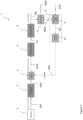
- Figure 1 shows a schematic view of a first exemplary embodiment of a gas sensing device 1 according to the disclosure.
- a gas sensing device for sensing one or more gases in a mixture of gases comprises:
- the first trained model based algorithm processor is implemented as a gated recurrent unit regressor.
- the second trained model based algorithm processor 9 is implemented as a deep neural network.
- the signal samples SIG of the chemo-resistive sensors 2 are received and preprocessed by the preprocessing processor 3. Then, the needed sets of feature values FV are directly extracted by the feature extraction processor 5 from the preprocessed signal samples PSS. In a last step, these sets of feature values FV are feed to a first trained model based algorithm processor 6, which may be a gated recurrent unit regression network doing the sensing results SR. These sensing results SR, however, are heavily influenced by drift.
- the proposed approach uses an additional machine-learning algorithm, in particular a reinforcement learning algorithm, to "learn" an adaptive mapping for the preprocessed signal samples PSS. Said mapping can then be used to convert the preprocessed signal samples PSS into drift-corrected signal samples DCS, ideally correcting the occurring drift over time.
- Sensing results SR derived from sets of feature values FV based on these drift-corrected signal samples DCS are now supposed to be more accurate than the sensing results SR derived from sets of feature values FV based on the unmapped preprocessed signal samples PSS, i.e. the proposed solution improves the sensing results SR for chemo-resistive sensors 2 that drift over time.
- Figure 1 shows the processing flow of the gas sensing device 1 during an operational phase under the assumption that the first trained model of the sensing result processor 6 and the second trained model of the update processor 8 are fully trained.
- the disclosure refers to a method for operating gas a sensing device 1 for sensing one or more gases in a mixture of gases, wherein the gas sensing device 1 comprises one or more chemo-resistive gas sensors 2, wherein the method comprises the steps of:
- Figure 2 shows a schematic view of a second exemplary embodiment of a gas sensing device 1 according to the disclosure.
- the second trained model based algorithm processor 9 is a reinforcement learning processor and the second trained model is a reinforcement learning model, wherein the gas sensing device 1 comprises a reward processor 11 configured for calculating a reward REW, which is fed to an input side of the reinforcement learning processor 9 during the training procedure TP, in order to train the reinforcement learning model.
- the reward processor 11 is configured for calculating the reward REW depending on the sensor results SR created by the sensing result processor 6 during the training procedure TP and depending on reference sensing results RSR provided by an external source for the training procedure TP.
- Figure 2 shows the processing flow of the gas sensing device 1 during an initial training phase TP when the second trained model based algorithm processor 9 is still not trained or during a subsequent training phase TP when the second trained model based algorithm processor 9 has to be trained again because the drift has significantly changed (e.g. it has become more severe, for example, from linear to exponential), wherein the reward REW is calculated from the sensor results SR created by the sensing result processor 6 during the training procedure TP and depending on reference sensing results RSR provided by an external source for the training procedure TP.
- the reward REW is calculated from the sensor results SR created by the sensing result processor 6 during the training procedure TP and depending on reference sensing results RSR provided by an external source for the training procedure TP.
- Figure 3 shows a schematic view of a third exemplary embodiment of a gas sensing device 1 according to the disclosure.
- the reward processor 11 is configured for calculating the reward REW depending on the sets of feature values FV created by the feature extraction processor 5 during the TP procedure by analyzing a first subset of the feature values FV of each set of feature values FV and by analyzing a second subset of the feature values FV of each set of feature values FV, wherein the feature values FV of the first subset are more drift-dependent than the feature values FV of the second subset.
- Figure 3 shows the processing flow of the gas sensing device 1 during an initial training phase TP when the second trained model based algorithm processor 9 is still not trained or during a subsequent training phase TP when the second trained model based algorithm processor 9 has to be trained again because the drift has significantly changed (e.g. it has become more severe, for example, from linear to exponential), wherein the reward REW is calculated from the sets of feature values FV created by the feature extraction processor 5 during the training procedure TP by analyzing a first subset of the feature values FV of each set of feature values FV and by analyzing a second subset of the feature values FV of each set of feature values FV, wherein the feature values FV of the first subset are more drift-dependent than the feature values FV of the second subset.
- the reward REW is calculated from the sets of feature values FV created by the feature extraction processor 5 during the training procedure TP by analyzing a first subset of the feature values FV of each set of feature values FV and by analyzing a second subset of the feature values FV of
- the current state STA must be constructed / observed by the state processor 7.
- the states STA are based on preprocessed signal samples PSS observed in the current update step and on information gathered during a selection of previous update steps (number of steps and their indices relative to the current one can be configured).
- the current mapping function MPF needs to be included in the state STA, enabling the second trained model based algorithm processor 9 (the agent) to evaluate how the current mapping function MPF affects the observed preprocessed signal samples PSS and to determine how it should be improved.
- One common configuration choice is to base the state STA on preprocessed signal samples PSS observed in the current and every tenth outputs from the previous 200 update steps (previously observed preprocessed signal samples PSS stored in a memory). This data is then mapped according to the current mapping, yielding drift-corrected signal samples DCS from the corresponding update steps as they would have been observed with the current mapping (which has probably changed over the past 200 steps).
- the state processor 7 knows the current state STA (from which it is possible to infer the drift), this state STA is feed to the second trained model based algorithm processor (9), which may be a deep neural network (in deep Q-learning called "model") estimating the quality values QV for all possible update actions.
- Possible update actions are changes to the mapping function MPF like increase or decrease one of the mapping parameters (explained later) by an amount (correction factor) that can be configured or doing nothing. It is important to understand that they do not directly affect the preprocessed signal samples PSS. For example, the update action "do nothing" means the mapping function won't be changed in this update step, but it is still applied to the preprocessed signal samples PSS.
- ⁇ may be decreasing over time (common for deep-Q-learning).
- the number of layers and units per layer for the used deep neural network can be configured. A common choice would be to use 4 dense layers and 1000 units per layer.
- the used optimizer is Adam with a learning rate decreasing over time. This decrease may depend on how much the quality value estimate error decreased over the past episodes, wherein for example between 2 and 10 episodes are considered.
- mapping function MPF is applied to the preprocessed signal samples PSS.
- This mapping may be implemented as a vector (array) saving the underlying mapping parameters of a function approximating the drift.
- Two such functions have been implemented. They make explicit assumptions about the drift behavior. They may either assume it to be linear or exponential and simply additional to the "true" sensor outputs.
- the time t in the equations above correspond to the moment the considered preprocessed signal samples PSS have been observed / measured.
- An example of how the preprocessed signal samples PSS are mapped is shown in Figure 5 .
- the sensing results SR may be leveraged relative to the reference sensing results RSR (true gas concentrations, ground truth) for the reward REW.
- RSR reference sensing results
- Different options for the reward function have been implemented.
- the best performing choice turned out to be the negative Euclidean distance between the sensing results SR and the reference sensing results RSR. This can be formulated in the following way, where y ⁇ R 2 is the sensing result SR y ⁇ ⁇ ⁇ R 2 the reference sensing result, r gt the reward REW, and ⁇ .
- FIG. 7 An example of how the reward REW over one episode can look like is shown in Fig-ure 7 .
- the disclosed approach can be - as shown in Figure 3 - adapted to the case where the reference sensing results RSR are not available by leveraging sets of feature values FV directly extracted from the drift-corrected signal samples DCS and which are differently affected from drift.
- a reward REW can be judiciously built, for example, by combining drift dependent feature values FV (e.g. time features), F d (t), and features values FV immune to baseline drift, F nd (t) (e.g. frequency dependent features) as described below.
- the ratio of drift independent and drift dependent features may be monitored at the lower gas concentrations C gas_min (or other reference value which occurs periodically) as illustrated in Figure 6 where after a few weeks (5 in the experiments) the ratio has considerably decreased (due to the drift of the sensitivity feature values FV versus the total harmonic distortion).
- C gas_min or other reference value which occurs periodically
- the correlation between drifting and non-drifting feature values FV can be obtained and a polynomial equation extracted for a given time interval.
- the parameter of this polynomial fit can be monitored over time and used to build the reward REW.
- the resistance of a heater of the chemo-resistive gas sensor(s) 2 could also be used as 'non-drifting' feature value FV (or alternative reference signal available at the sensor 2, which does not vary with the gas concentration).
- the second trained model based algorithm processor 9 For training, as common in DQN, the second trained model based algorithm processor 9 relies on information observed in the previous N steps (N configurable, common choice is 10'000). First, a training batch needs to be constructed. Thereby, the second trained model based algorithm processor 9 loads information from randomly sampled previous steps, i.e. it loads their current states STA, taken updates UPD, observed reward REW, and next states STA. This step includes the construction of these states STA as described previously. Based on the sampled current states STA, the quality values QV are estimated for all possible actions using the described DNN.
- the model (first DNN) is then trained ( ⁇ fitted') using with this constructed batch.
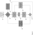
- Figure 4 illustrates an exemplary method for operating the second or third exemplary embodiment of a gas sensing device 1 according to the disclosure.
- the update processor 8 is configured to detect a change of a drift behavior of one or more of the one or more chemo-resistive gas sensors 2, which can not be compensated by the updates UPD.
- the update processor 8 is configured to initiate a training procedure TP for training the second trained model in case that the change of the drift behavior, which can not be compensated by the updates UPD, is detected.
- Figure 4 illustrates a typical implementation of the invention.
- a GRU regression network estimating the gas concentrations and the DNN need to be trained in the lab.
- the gas sensing device 1 can then be operated on a sensor board, its sensing results SR being continuously monitored / checked whether one of the chemo-resistive gas sensors 2 changes its drift behavior in a step S2. As long as no change of the drift behavior is detected, the operational mode is maintained in step S3.
- the DNN model needs to be trained and/or updated.
- the sensor is taken offline and the reference sensing results RSR are gathered (by for example consulting an analyzer, other sensors in operation, internet connection to a monitoring station, etc.) in step S4.
- the sensing results SR and the gathered reference sensing results RSR are now used to build a ground-truth aided reward REW in step S5 and to train a DNN model (RL agent) in step S6 as detailed above and illustrated in Figure 2 .
- a check is performed whether the training was successful. Further training may be executed based on further data gathered in step S8.
- a second implementation here is to compare feature values FV that are affected in a different way by the drift (e.g. time and frequency domain features in case of baseline drift) and build in step S5 a features based reward REW as detailed above and illustrated in Figure 3 .
- the trained second model based algorithm processor 9 can be used online on the gas sensing device 1 to correct the preprocessed signal samples PSS by gradually adapting the assumed underlying drift parameters (depending on the taken assumption about the drift) in step S9.
- the DNN now can be used as in Figure 1 . Therefore, this proposed implementation can be viewed as a sophisticated way of learning the drift.
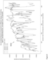
- Figure 5 illustrates exemplary sensing results SR over time of a gas sensing device 1 according to the disclosure and exemplary prior art sensing results PSR over time of a gas sensing device according to prior art compared to reference sensing results RSR.
- Figure 6 illustrates an exemplary features ratio F nd (t)/F d (t) over time for different time intervals, wherein F d (t) is a drifting feature value FV of the sets of feature values FV and F nd (t) is a non-drifting feature value FV of the sets of feature values FV.
- Figure 7 illustrates exemplary sensing results SR of a gas sensing device 1 according to the disclosure and exemplary prior art sensing results PSR of a gas sensing device according to prior art compared to reference sensing results RSR for nitrogen dioxide and ozone as well as the associated reward REW of the gas sensing device 1 according to the disclosure and the associated prior art reward PRW of the gas sensing device according to prior art.
- the described approach has been tested on upward drifting multigas sensor data.
- the second trained model based algorithm processor 9 has been trained with 550 episodes with various drifts (positive as well as negative). For these experiments, the drift was mostly linear and equal for all of four chemo-resistive gas sensors 2 used in the experiments.
- the device 1 is able to almost perfectly align the sensing results SR to the reference sensing results RSL.
- Figure 8 illustrates an exemplary accumulated reward REW for different correction factors over time.
- Figure 8 shows the accumulated reward REW per episode for different correction factors of a 0 and a 1.
- the performance is influenced by this choice, for example using a factor of 10 -5 for a 1 seems to work better than 10 -4 .
- this factor is a design choice needed to be made carefully based on the severity of the drift.
- Figure 9 illustrates an exemplary accumulated reward REW for different depreciation factors over time.
- gamma can be viewed as the depreciation factor in DQN.
- a plot of the accumulated reward per episode is shown in Figure 9 .
- the agent is able to learn something useful (i.e. improve the reward REW over time) for all presented cases.
- aspects have been described in the context of an apparatus, it is clear that these aspects also represent a description of the corresponding method, where a block or device corresponds to a method step or a feature of a method step. Analogously, aspects described in the context of a method step also represent a description of a corresponding block or item or feature of a corresponding apparatus.
Landscapes
- Chemical & Material Sciences (AREA)
- Life Sciences & Earth Sciences (AREA)
- Engineering & Computer Science (AREA)
- Health & Medical Sciences (AREA)
- Physics & Mathematics (AREA)
- Immunology (AREA)
- Biochemistry (AREA)
- General Health & Medical Sciences (AREA)
- General Physics & Mathematics (AREA)
- Pathology (AREA)
- Analytical Chemistry (AREA)
- Combustion & Propulsion (AREA)
- Medicinal Chemistry (AREA)
- Food Science & Technology (AREA)
- Chemical Kinetics & Catalysis (AREA)
- Mathematical Physics (AREA)
- Evolutionary Computation (AREA)
- Artificial Intelligence (AREA)
- Electrochemistry (AREA)
- Investigating Or Analyzing Materials By The Use Of Electric Means (AREA)
Abstract
Description
- Embodiments relate to a gas sensing device for sensing one or more gases in a mixture of gases. Further embodiments relate to a method for operating such gas sensing device. More particular, the disclosure deals with the estimation of gas concentrations through the use of chemo-resistive gas sensors.
- Chemo-resistive gas sensors change their electrical properties in the presence of gases such as nitrogen dioxide (NO2), ozone (03), ammonia (NH3) or carbon monoxide (CO) so that a concentration of such gases in a mixture of gases may be determined by measuring the electrical properties of one or more chemo-resistive gas sensors. However, chemo-resistive gas sensors are prone to the effect of drifting, which is the effect that the sensor outputs change (i.e. drift) over time for similar gas concentrations. This makes the estimation of the gas concentrations harder the longer the chemo-resistive gas sensors are in operation up to the point where it, unfortunately, fails completely. The drift behavior of gas sensors in general is a well-known and documented problem.
- A gas sensing device for sensing one or more gases in a mixture of gases is provided. The gas sensing device comprises:
- one or more chemo-resistive gas sensors, wherein each of the gas sensors is configured for generating signal samples corresponding to concentrations of the one or more gases in the mixture of gases;
- a preprocessing processor configured for preprocessing the signal samples in order to generate a preprocessed signal sample for each of the signal samples;
- a drift correction processor configured for applying a mapping function to each of the preprocessed signal samples in order to create a drift-corrected signal sample for each of the preprocessed signal samples, wherein the drift correction processor is configured for receiving updates for the mapping function, wherein each update initiates an update step of a plurality of consecutive update steps;
- a feature extraction processor configured for extracting a set of feature values from each of the drift-corrected signal samples based on characteristics of the received drift-corrected signal samples;
- a sensing result processor configured for creating for each of the gases a sensing result for each of the sets of feature values, wherein the sensing result processor comprises a first trained model based algorithm processor and a first trained model for the first trained model based algorithm processor, wherein the sets of feature values are fed to an input side of the first trained model based algorithm processor, and wherein the sensing results are provided at an output side of the first trained model based algorithm processor;
- a state processor configured for determining a state of the gas sensing device for a current update step of the update steps, wherein the state comprises at least a part of the preprocessed signal samples of the current update step, at least a part of the preprocessed signal samples of previous update steps of the update steps and the mapping function of the current update step; and
- an update processor configured for providing the update for a subsequent update step subsequently following the current update step to the drift correction processor, wherein the update processor comprises a second trained model based algorithm processor, a second trained model for the second trained model based algorithm processor and an update action processor, wherein the state of the current update step is fed to an input side of the second trained model based algorithm processor, wherein a quality value for each possible update action of a plurality of update actions is provided at an output side of the second trained model based algorithm processor, wherein the update action processor is configured for calculating the update for the subsequent update step by applying the possible update action, which has a highest quality value of the quality values of the current update step, to the mapping function of the current update step.
- The one or more chemo-resistive gas sensors may be reduced graphene gas sensors, where the base material is functionalized with specific chemicals, e.g. with platinum (Pt), or manganese dioxide (MnO2), so that each of the gas sensors is sensitive for a specific gas, e.g. for nitrogen dioxide (NO2), ozone (O3), ammonia (NH3) or carbon monoxide (CO). In doing so, the interaction between graphene sheets and absorbed gas analytes influences the electronic structure of the material depending on the mixture of gases, resulting in altered charge carrier concentration and changed electrical conductance.
- In case of multi-gas sensing a multi-gas sensor array comprising a plurality of chemo-resistive gas sensors having dissimilar selectivity may be used. Due to the different sensitivity towards various gas molecules, resistances of the gas sensors change in disparate patterns, making it possible to analyze complicated gas mixtures with one single sensor array.
- A signal sample is a sequence consisting of time-discrete signal values, wherein the signal values are output by one of the gas sensors.
- The term processor refers to an electronic device configured for specific task. A processor may comprise hardware or a combination of hardware and software. Different processors may share hardware components and/or software components.
- The pre-processing processor is configured for suppressing and/or compensating of artifacts in the signal samples and/or noise in the signal samples and/or invalid signal samples due to malfunctioning gas sensors in order to produce more reliable preprocessed signal samples.
- The drift correction processor is configured for applying a mapping function to each of the preprocessed signal samples in order to create a drift-corrected signal sample for each of the preprocessed signal samples during an operational phase. The drift correction processor is configured for receiving updates for the mapping function during the operation phase, wherein each update initiates an update step of a plurality of consecutive update steps. A new update step, in which a new update for the mapping function is provided, may be initiated, for example, every 60 seconds.
- The feature extraction processor is configured for receiving the drift-corrected signal samples and for extracting a set of feature values from each of the received drift-corrected signal samples of each of the gas sensors based on characteristics of the received drift-corrected signal samples of the respective gas sensor. The features may be based on dynamic characteristics of the signal samples.
- A trained model based algorithm processor is a processor, which is capable of machine learning. The machine learning is done in a preoperational training phase in which trained models are developed by comparing actual output values of the trained model based algorithm stage with desired output values of the trained model based algorithm stage for defined inputs of the trained model based algorithm stage. The trained models have a predefined structure, wherein a parametrization of the predefined structure is done during the training phase. The trained models comprise the learned content after the training phase is finished. In an operational phase for producing processing results one or more of the trained models from the training phase are used to process their input data.
- In the training phase, the plurality of trained models can be established and afterwards stored at the gas sensing device. The trained models may differ in the structures and/or the parameters. During the operation phase the most appropriate trained model may be selected depending on the specific use-case.
- The state processor is configured for determining a state of the gas sensing device for a current update step of the update steps, wherein the state comprises at least a part of the preprocessed signal samples of the current update step, at least a part of the preprocessed signal samples of previous update steps of the update steps and the mapping function of the current update step. For example, the state processor may use every tenth preprocessed signal sample of the previous 200 update steps.
- The update processor is configured for providing the update for a subsequent update step subsequently following the current update step to the drift correction processor, wherein the update processor comprises a second trained model based algorithm processor, a second trained model for the second trained model based algorithm processor and an update action processor, wherein the state of the current update step is fed to an input side of the second trained model based algorithm processor, wherein a quality value for each possible update action of a plurality of update actions is provided at an output side of the second trained model based algorithm processor, wherein the update action processor is configured for calculating the update for the subsequent update step by applying the possible update action, which has a highest quality value of the quality values of the current update step, to the mapping function of the current update step.
- The disclosure provides a new approach to tackle the drift problem of chemo-resistive gas sensors using a drift correction processor for applying a mapping function to the preprocessed signal samples and a second trained model based algorithm processor for providing updates for the mapping function. The core of the idea is the presence of a second trained model based algorithm processor, which explores how different update for the mapping function applied to the preprocessed signal samples affect the performance of the predictions and eventually selects the best update for the mapping function for the specific drift experienced in the field without any a-priori knowledge of the drift rate.
- The approach can be elegantly overlapped to an existing signal processing and algorithm flows with the goal of stabilizing the drift and improving the final gas predictions. In other words, calibration models trained for un-drifted data can be made usable for drifted data as well in real-world conditions.
- The gas sensing device according to the disclosure provides a better long-term stability of the sensing results than approaches which seek to solve the drifting problem by training the first trained model of the first trained model based algorithm processor of the sensing result processor with drifted data as such data do usually not cover all possible drifting scenarios. Even if that would not be a problem, training the sensing result processor in the field on such a great amount of data would exceed the possibilities of the used processing units.
- Furthermore, the gas sensing device according to the disclosure provides a better long-term stability of the sensing results than approaches which seek to solve the drifting problem by regularly updating the baseline, which normalizes the sensor outputs, as this baseline has to be calculated with sensor exposure to 0 ppb target gas periodically, which again implies restrictions on the applicability of the algorithms.
- According to embodiments of the disclosure, the update processor is configured to detect a change of a drift behavior of one or more of the one or more chemo-resistive gas sensors, which can not be compensated by the updates. The change of the drift behavior, which can not be compensated by the updates may be detected by analyzing the quality values for each of the possible update actions. For example, a change in the drift behavior may be assumed if the highest quality factor is smaller than a preset value.
- According to embodiments of the disclosure, the update processor is configured to initiate a training procedure for training the second trained model in case that the change of the drift behavior, which can not be compensated by the updates, is detected. By such features, the long-term stability of the sensing results may be further increased.
- According to embodiments of the disclosure, the second trained model based algorithm processor is a reinforcement learning processor and the second trained model is a reinforcement learning model, wherein the gas sensing device comprises a reward processor configured for calculating a reward, which is fed to an input side of the reinforcement learning processor during the training procedure, in order to train the reinforcement learning model. Some applications of known reinforcement learning principles in different fields are described in References [1] and [2]. However, it is possible to use other machine- learning approaches for the second trained model based algorithm processor
- According to embodiments of the disclosure, the reward processor is configured for calculating the reward depending on the sensor results created by the sensing result processor during the training procedure and depending on reference sensing results provided by an external source for the training procedure. By such features, the long-term stability of the sensing results may be further increased.
- According to embodiments of the disclosure, the reward processor is configured for calculating the reward depending on the sets of feature values created by the feature extraction processor during the training procedure by analyzing a first subset of the feature values of each set of feature values and by analyzing a second subset of the feature values of each set of feature values, wherein the feature values of the first subset are more drift-dependent than the feature values of the second subset.
- By such features, the long-term stability of the sensing results may be further increased. Moreover, no reference sensing results are needed.
- According to embodiments of the disclosure, the first trained model based algorithm processor is implemented as a gated recurrent unit regressor. A gated recurrent regressor is recurrent neural network using gating mechanisms.
- According to embodiments of the disclosure, the second trained model based algorithm processor is implemented as a deep neural network. A deep neural network is an artificial neural network with multiple layers between the input and output layers.
- Further disclosed is a method for operating a gas sensing device for sensing one or more gases in a mixture of gases, wherein the gas sensing device comprises one or more chemo-resistive gas sensors, wherein the method comprises the steps of:
- using each of the gas sensors for generating signal samples corresponding to concentrations of the one or more gases in the mixture of gases;
- using a preprocessing processor of the gas sensing device for preprocessing the signal samples in order to generate a preprocessed signal sample for each of the signal samples;
- using a drift correction processor of the gas sensing device for applying a mapping function to each of the preprocessed signal samples in order to create a drift-corrected signal sample for each of the preprocessed signal samples, wherein the drift correction processor is configured for receiving updates for the mapping function, wherein each update initiates an update step of a plurality of consecutive update steps;
- using a feature extraction processor of the gas sensing device for extracting a set of feature values from each of the drift-corrected signal samples based on characteristics of the received drift-corrected signal samples;
- using a sensing result processor of the gas sensing device for creating for each of the gases a sensing result for each of the sets of feature values, wherein the sensing result processor comprises a first trained model based algorithm processor and a first trained model for the first trained model based algorithm processor, wherein the sets of feature values are fed to an input side of the first trained model based algorithm processor, and wherein the sensing results are provided at an output side of the first trained model based algorithm processor;
- using a state processor of the gas sensing device for determining a state of the gas sensing device for a current update step of the update steps, wherein the state comprises at least a part of the preprocessed signal samples of the current update step, at least a part of the preprocessed signal samples of previous update steps of the update steps and the mapping function of the current update step; and
- using an update processor of the gas sensing device for providing the update for a subsequent update step subsequently following the current update step to the drift correction processor, wherein the update processor comprises a second trained model based algorithm processor, a second trained model for the second trained model based algorithm processor and an update action processor, wherein the state of the current update step is fed to an input side of the second trained model based algorithm processor, wherein a quality value for each possible update action of a plurality of update actions is provided at an output side of the second trained model based algorithm processor, wherein the update action processor is configured for calculating the update for the subsequent update step by applying the possible update action, which has a highest quality value of the quality values of the current update step, to the mapping function of the current update step.
- Preferred embodiments of the invention are subsequently discussed with respect to the accompanying drawings, in which:
- Figure 1
- shows a schematic view of a first exemplary embodiment of a gas sensing device according to the disclosure;
- Figure 2
- shows a schematic view of a second exemplary embodiment of a gas sensing device according to the disclosure;
- Figure 3
- shows a schematic view of a third exemplary embodiment of a gas sensing device according to the disclosure;
- Figure 4
- illustrates an exemplary method for operating the second or third exemplary embodiment of a gas sensing device according to the disclosure;
- Figure 5
- illustrates exemplary sensing results over time of a gas sensing device according to the disclosure and exemplary prior art sensing results over time of a gas sensing device according to prior art compared to reference sensing results;
- Figure 6
- illustrates an exemplary features ratio between a non-drifting feature value of the sets of feature values and a drifting feature value of the sets of feature values over time for different time intervals;
- Figure 7
- illustrates exemplary sensing results of a gas sensing device according to the disclosure and exemplary prior art sensing results of a gas sensing device according to prior art compared to reference sensing results for nitrogen dioxide and ozone as well as the associated reward and the associated prior art reward;
- Figure 8
- illustrates an exemplary accumulated reward for different correction factors overtime; and
- Figure 9
- illustrates an exemplary accumulated reward for different depreciation factors over time.
- Equal or equivalent elements or elements with equal or equivalent functionality are denoted in the following description by equal or equivalent reference numerals.
- In the following description, a plurality of details is set forth to provide a more thorough explanation of embodiments of the present disclosure. However, it will be apparent to those skilled in the art that embodiments of the present disclosure may be practiced without these specific details. In other instances, well-known structures and devices are shown in block diagram form rather than in detail in order to avoid obscuring embodiments of the present disclosure. In addition, features of the different embodiments described hereinafter may be combined with each other, unless specifically noted otherwise.
-
Figure 1 shows a schematic view of a first exemplary embodiment of agas sensing device 1 according to the disclosure. - A gas sensing device for sensing one or more gases in a mixture of gases. The
gas sensing device 1 comprises: - one or more chemo-
resistive gas sensors 2, wherein each of thegas sensors 2 is configured for generating signal samples SIG corresponding to concentrations of the one or more gases in the mixture of gases; - a
preprocessing processor 3 configured for preprocessing the signal samples SIG in order to generate a preprocessed signal sample PSS for each of the signal samples SIG; - a
drift correction processor 4 configured for applying a mapping function MPF to each of the preprocessed signal samples PSS in order to create a drift-corrected signal sample DCS for each of the preprocessed signal samples PSS, wherein thedrift correction processor 4 is configured for receiving updates UPD for the mapping function MPF, wherein each update UPD initiates an update step of a plurality of consecutive update steps; - a
feature extraction processor 5 configured for extracting a set of feature values FV from each of the drift-corrected signal samples DCS based on characteristics of the received drift-corrected signal samples DCS; - a
sensing result processor 6 configured for creating for each of the gases a sensing result SR for each of the sets of feature values FV, wherein thesensing result processor 6 comprises a first trained model based algorithm processor and a first trained model for the first trained model based algorithm processor, wherein the sets of feature values FV are fed to an input side of the first trained model based algorithm processor, and wherein the sensing results SR are provided at an output side of the first trained model based algorithm processor; - a
state processor 7 configured for determining a state STA of thegas sensing device 1 for a current update step of the update steps, wherein the state STA comprises at least a part of the preprocessed signal samples PSS of the current update step, at least a part of the preprocessed signal samples PSS of previous update steps of the update steps and the mapping function MPF of the current update step; and - an
update processor 8 configured for providing the update UPD for a subsequent update step subsequently following the current update step to thedrift correction processor 4, wherein theupdate processor 8 comprises a second trained model basedalgorithm processor 9, a second trained model for the second trained model basedalgorithm processor 9 and anupdate action processor 10, wherein the state STA of the current update step is fed to an input side of the second trained model basedalgorithm processor 9, wherein a quality value QV for each possible update action of a plurality of update actions is provided at an output side of the second trained model basedalgorithm processor 9, wherein theupdate action processor 10 is configured for calculating the update UPD for the subsequent update step by applying the possible update action, which has a highest quality value QV of the quality values QV of the current update step, to the mapping function MPF of the current update step. - According to embodiments of the disclosure, the first trained model based algorithm processor is implemented as a gated recurrent unit regressor.
- According to embodiments of the disclosure, the second trained model based
algorithm processor 9 is implemented as a deep neural network. - In prior art approaches, the signal samples SIG of the chemo-
resistive sensors 2 are received and preprocessed by thepreprocessing processor 3. Then, the needed sets of feature values FV are directly extracted by thefeature extraction processor 5 from the preprocessed signal samples PSS. In a last step, these sets of feature values FV are feed to a first trained model basedalgorithm processor 6, which may be a gated recurrent unit regression network doing the sensing results SR. These sensing results SR, however, are heavily influenced by drift. - In contrast to that, the proposed approach uses an additional machine-learning algorithm, in particular a reinforcement learning algorithm, to "learn" an adaptive mapping for the preprocessed signal samples PSS. Said mapping can then be used to convert the preprocessed signal samples PSS into drift-corrected signal samples DCS, ideally correcting the occurring drift over time. Sensing results SR derived from sets of feature values FV based on these drift-corrected signal samples DCS are now supposed to be more accurate than the sensing results SR derived from sets of feature values FV based on the unmapped preprocessed signal samples PSS, i.e. the proposed solution improves the sensing results SR for chemo-
resistive sensors 2 that drift over time. -
Figure 1 shows the processing flow of thegas sensing device 1 during an operational phase under the assumption that the first trained model of thesensing result processor 6 and the second trained model of theupdate processor 8 are fully trained. - In a further aspect, the disclosure refers to a method for operating gas a
sensing device 1 for sensing one or more gases in a mixture of gases, wherein thegas sensing device 1 comprises one or more chemo-resistive gas sensors 2, wherein the method comprises the steps of: - using each of the
gas sensors 2 for generating signal samples SIG corresponding to concentrations of the one or more gases in the mixture of gases; - using a
preprocessing processor 3 of thegas sensing device 1 for preprocessing the signal samples SIG in order to generate a preprocessed signal sample PSS for each of the signal samples SIG; - using a
drift correction processor 4 of thegas sensing device 1 for applying a mapping function MPF to each of the preprocessed signal samples PSS in order to create a drift-corrected signal sample DCS for each of the preprocessed signal samples PSS, wherein thedrift correction processor 4 is configured for receiving updates UPD for the mapping function MPF, wherein each update UPD initiates an update step of a plurality of consecutive update steps; - using a
feature extraction processor 5 of thegas sensing device 1 for extracting a set of feature values FV from each of the drift-corrected signal samples DCS based on characteristics of the received drift-corrected signal samples DCS; - using a
sensing result processor 6 of thegas sensing device 1 for creating for each of the gases a sensing result SR for each of the sets of feature values FV, wherein thesensing result processor 6 comprises a first trained model based algorithm processor and a first trained model for the first trained model based algorithm processor, wherein the sets of feature values FV are fed to an input side of the first trained model based algorithm processor, and wherein the sensing results SR are provided at an output side of the first trained model based algorithm processor; - using a
state processor 7 of thegas sensing device 1 for determining a state STA of thegas sensing device 1 for a current update step of the update steps, wherein the state STA comprises at least a part of the preprocessed signal samples PSS of the current update step, at least a part of the preprocessed signal samples PSS of previous update steps of the update steps and the mapping function MPF of the current update step; and - using an
update processor 8 of thegas sensing device 1 for providing the update UPD for a subsequent update step subsequently following the current update step to thedrift correction processor 4, wherein theupdate processor 8 comprises a second trained model basedalgorithm processor 9, a second trained model for the second trained model basedalgorithm processor 9 and anupdate action processor 10, wherein the state STA of the current update step is fed to an input side of the second trained model basedalgorithm processor 9, wherein a quality value QV for each possible update action of a plurality of update actions is provided at an output side of the second trained model basedalgorithm processor 9, wherein theupdate action processor 10 is configured for calculating the update UPD for the subsequent update step by applying the possible update action, which has a highest quality value QV of the quality values of the current update step, to the mapping function MPF of the current update step. -
Figure 2 shows a schematic view of a second exemplary embodiment of agas sensing device 1 according to the disclosure. - According to embodiments of the disclosure, the second trained model based
algorithm processor 9 is a reinforcement learning processor and the second trained model is a reinforcement learning model, wherein thegas sensing device 1 comprises areward processor 11 configured for calculating a reward REW, which is fed to an input side of thereinforcement learning processor 9 during the training procedure TP, in order to train the reinforcement learning model. - According to embodiments of the disclosure, the
reward processor 11 is configured for calculating the reward REW depending on the sensor results SR created by thesensing result processor 6 during the training procedure TP and depending on reference sensing results RSR provided by an external source for the training procedure TP. -
Figure 2 shows the processing flow of thegas sensing device 1 during an initial training phase TP when the second trained model basedalgorithm processor 9 is still not trained or during a subsequent training phase TP when the second trained model basedalgorithm processor 9 has to be trained again because the drift has significantly changed (e.g. it has become more severe, for example, from linear to exponential), wherein the reward REW is calculated from the sensor results SR created by thesensing result processor 6 during the training procedure TP and depending on reference sensing results RSR provided by an external source for the training procedure TP. -
Figure 3 shows a schematic view of a third exemplary embodiment of agas sensing device 1 according to the disclosure. - According to embodiments of the disclosure, the
reward processor 11 is configured for calculating the reward REW depending on the sets of feature values FV created by thefeature extraction processor 5 during the TP procedure by analyzing a first subset of the feature values FV of each set of feature values FV and by analyzing a second subset of the feature values FV of each set of feature values FV, wherein the feature values FV of the first subset are more drift-dependent than the feature values FV of the second subset. -
Figure 3 shows the processing flow of thegas sensing device 1 during an initial training phase TP when the second trained model basedalgorithm processor 9 is still not trained or during a subsequent training phase TP when the second trained model basedalgorithm processor 9 has to be trained again because the drift has significantly changed (e.g. it has become more severe, for example, from linear to exponential), wherein the reward REW is calculated from the sets of feature values FV created by thefeature extraction processor 5 during the training procedure TP by analyzing a first subset of the feature values FV of each set of feature values FV and by analyzing a second subset of the feature values FV of each set of feature values FV, wherein the feature values FV of the first subset are more drift-dependent than the feature values FV of the second subset. - This section describes how the general invention described in
Figures 1-3 may be implemented in chronological order, i.e. in the order the algorithm executes the different parts per update step. A new update step can be performed each time enough new preprocessed signal samples PSS have been observed to construct a new set of feature values (done in thepre-processing processor 3/ feature extraction processor 5), e.g. one update step every 60 seconds. Furthermore, it shall be noted that the following described approach implements the idea of deep Q-learning (DQN), but could have also been done implementing other machine learning algorithms. Some known gradient descent methods (like the Actor-Critic approach) could be also suited. - At the beginning of each update step the current state STA must be constructed / observed by the
state processor 7. In the described implementation, the states STA are based on preprocessed signal samples PSS observed in the current update step and on information gathered during a selection of previous update steps (number of steps and their indices relative to the current one can be configured). Furthermore, the current mapping function MPF needs to be included in the state STA, enabling the second trained model based algorithm processor 9 (the agent) to evaluate how the current mapping function MPF affects the observed preprocessed signal samples PSS and to determine how it should be improved. - One common configuration choice is to base the state STA on preprocessed signal samples PSS observed in the current and every tenth outputs from the previous 200 update steps (previously observed preprocessed signal samples PSS stored in a memory). This data is then mapped according to the current mapping, yielding drift-corrected signal samples DCS from the corresponding update steps as they would have been observed with the current mapping (which has probably changed over the past 200 steps).
- Now that the
state processor 7 knows the current state STA (from which it is possible to infer the drift), this state STA is feed to the second trained model based algorithm processor (9), which may be a deep neural network (in deep Q-learning called "model") estimating the quality values QV for all possible update actions. Possible update actions are changes to the mapping function MPF like increase or decrease one of the mapping parameters (explained later) by an amount (correction factor) that can be configured or doing nothing. It is important to understand that they do not directly affect the preprocessed signal samples PSS. For example, the update action "do nothing" means the mapping function won't be changed in this update step, but it is still applied to the preprocessed signal samples PSS. In deep Q-learning, the update action with the highest estimated quality value QV is chosen with probability p=1- ε and a random action with probability p=ε (called ε-greedy policy). In this implementation ε may be decreasing over time (common for deep-Q-learning). - The number of layers and units per layer for the used deep neural network can be configured. A common choice would be to use 4 dense layers and 1000 units per layer. The used optimizer is Adam with a learning rate decreasing over time. This decrease may depend on how much the quality value estimate error decreased over the past episodes, wherein for example between 2 and 10 episodes are considered.
- Next, the (probably altered) mapping function MPF is applied to the preprocessed signal samples PSS. This mapping may be implemented as a vector (array) saving the underlying mapping parameters of a function approximating the drift. Two such functions have been implemented. They make explicit assumptions about the drift behavior. They may either assume it to be linear or exponential and simply additional to the "true" sensor outputs. The parameters a_0 and a_1 are the mentioned mapping parameters (unknown) and t corresponds to the time:


- The drift can either be assumed to be the same or different for each of the chemo-
resistive gas sensors 2, resulting in the following number of different actions, wherefactor 4 is due to the two parameters of which each can be increased or decreased and +1 for the action "do nothing":

- The time t in the equations above correspond to the moment the considered preprocessed signal samples PSS have been observed / measured. An example of how the preprocessed signal samples PSS are mapped is shown in
Figure 5 . - As shown in
Figure 2 , the sensing results SR may be leveraged relative to the reference sensing results RSR (true gas concentrations, ground truth) for the reward REW. Different options for the reward function have been implemented. The best performing choice turned out to be the negative Euclidean distance between the sensing results SR and the reference sensing results RSR. This can be formulated in the following way, wherey ∈ R 2 is the sensing result SR

- An example of how the reward REW over one episode can look like is shown in
Fig- .ure 7 - The disclosed approach can be - as shown in
Figure 3 - adapted to the case where the reference sensing results RSR are not available by leveraging sets of feature values FV directly extracted from the drift-corrected signal samples DCS and which are differently affected from drift. By monitoring the relationship between such signals over time, a reward REW can be judiciously built, for example, by combining drift dependent feature values FV (e.g. time features), F d (t), and features values FV immune to baseline drift, F nd (t) (e.g. frequency dependent features) as described below. - The ratio of drift independent and drift dependent features may be monitored at the lower gas concentrations C gas_min (or other reference value which occurs periodically) as illustrated in
Figure 6 where after a few weeks (5 in the experiments) the ratio has considerably decreased (due to the drift of the sensitivity feature values FV versus the total harmonic distortion).
- If Δ (t, C gas_min ) increases, this is a sign of drift that needs to be correct and vice versa.
- Alternatively, the correlation between drifting and non-drifting feature values FV can be obtained and a polynomial equation extracted for a given time interval. The parameter of this polynomial fit can be monitored over time and used to build the reward REW.
- It should be noted that the resistance of a heater of the chemo-resistive gas sensor(s) 2 could also be used as 'non-drifting' feature value FV (or alternative reference signal available at the
sensor 2, which does not vary with the gas concentration). - For training, as common in DQN, the second trained model based
algorithm processor 9 relies on information observed in the previous N steps (N configurable, common choice is 10'000). First, a training batch needs to be constructed. Thereby, the second trained model basedalgorithm processor 9 loads information from randomly sampled previous steps, i.e. it loads their current states STA, taken updates UPD, observed reward REW, and next states STA. This step includes the construction of these states STA as described previously. Based on the sampled current states STA, the quality values QV are estimated for all possible actions using the described DNN. The same is done for the corresponding next states STA using a different DNN (referred to as the "target model"), which gets updated with the weights from the first DNN every M-th step (can be configured, usually set to M = 10). This procedure is common for DQN, as it is supposed to increase the stability of the algorithm. Now, the quality values QV for the update actions actually taken get updated according to the following formula, where ri is the reward in the i-th step, vmodel and vtarget_model the output of the corresponding models, γ the depreciation factor, α is the learning rate, and Si / S i+1 the current / next state STA:
- The model (first DNN) is then trained (`fitted') using with this constructed batch.
-
Figure 4 illustrates an exemplary method for operating the second or third exemplary embodiment of agas sensing device 1 according to the disclosure. - According to embodiments of the disclosure, the
update processor 8 is configured to detect a change of a drift behavior of one or more of the one or more chemo-resistive gas sensors 2, which can not be compensated by the updates UPD. - According to embodiments of the disclosure, the
update processor 8 is configured to initiate a training procedure TP for training the second trained model in case that the change of the drift behavior, which can not be compensated by the updates UPD, is detected. -
Figure 4 illustrates a typical implementation of the invention. In a step S1 a GRU regression network estimating the gas concentrations and the DNN need to be trained in the lab. Thegas sensing device 1 can then be operated on a sensor board, its sensing results SR being continuously monitored / checked whether one of the chemo-resistive gas sensors 2 changes its drift behavior in a step S2. As long as no change of the drift behavior is detected, the operational mode is maintained in step S3. - As soon as a certain drift-level is detected or a change in drift behavior is observed, the DNN model needs to be trained and/or updated. In one implementation, the sensor is taken offline and the reference sensing results RSR are gathered (by for example consulting an analyzer, other sensors in operation, internet connection to a monitoring station, etc.) in step S4. The sensing results SR and the gathered reference sensing results RSR are now used to build a ground-truth aided reward REW in step S5 and to train a DNN model (RL agent) in step S6 as detailed above and illustrated in
Figure 2 . In step S7, a check is performed whether the training was successful. Further training may be executed based on further data gathered in step S8. - The implementation described above is based on the true gas concentrations and can therefore be operated only when the 'ground truth' is available. If this restriction can be dropped, the disclosed approach becomes even more powerful, as it would explore the full self-adaptive nature of reinforcement learning.
- A second implementation here is to compare feature values FV that are affected in a different way by the drift (e.g. time and frequency domain features in case of baseline drift) and build in step S5 a features based reward REW as detailed above and illustrated in
Figure 3 . - After the training of the DNN model has finished, the trained second model based
algorithm processor 9 can be used online on thegas sensing device 1 to correct the preprocessed signal samples PSS by gradually adapting the assumed underlying drift parameters (depending on the taken assumption about the drift) in step S9. The DNN now can be used as inFigure 1 . Therefore, this proposed implementation can be viewed as a sophisticated way of learning the drift. -
Figure 5 illustrates exemplary sensing results SR over time of agas sensing device 1 according to the disclosure and exemplary prior art sensing results PSR over time of a gas sensing device according to prior art compared to reference sensing results RSR. -
Figure 6 illustrates an exemplary features ratio Fnd(t)/Fd(t) over time for different time intervals, wherein Fd(t) is a drifting feature value FV of the sets of feature values FV and Fnd(t) is a non-drifting feature value FV of the sets of feature values FV. -
Figure 7 illustrates exemplary sensing results SR of agas sensing device 1 according to the disclosure and exemplary prior art sensing results PSR of a gas sensing device according to prior art compared to reference sensing results RSR for nitrogen dioxide and ozone as well as the associated reward REW of thegas sensing device 1 according to the disclosure and the associated prior art reward PRW of the gas sensing device according to prior art. - The described approach has been tested on upward drifting multigas sensor data. The second trained model based
algorithm processor 9 has been trained with 550 episodes with various drifts (positive as well as negative). For these experiments, the drift was mostly linear and equal for all of four chemo-resistive gas sensors 2 used in the experiments. - In
Figure 7 , the upper two subplots show nicely how the proposed approach is able to improve the estimation of the gas concentrations. The used gas sensor data starts to drift after 300 minutes. One can see that the estimation without RL almost instantly starts to fail, i.e. the sensing results SR simply drops to zero for both gases. With RL, the estimation continues to work till the end of the episode. This is also reflected in the last subplot showing the reward REW for these two cases. Over all, thegas sensing device 1 implementing the proposed drift correction technique achieves a much higher reward REW. - It can be seen how the
device 1 is able to almost perfectly align the sensing results SR to the reference sensing results RSL. -
Figure 8 illustrates an exemplary accumulated reward REW for different correction factors over time. -
Figure 8 shows the accumulated reward REW per episode for different correction factors of a 0 and a 1. One can see that the performance is influenced by this choice, for example using a factor of 10-5 for a 1 seems to work better than 10-4 . Generally, this factor is a design choice needed to be made carefully based on the severity of the drift. -
Figure 9 illustrates an exemplary accumulated reward REW for different depreciation factors over time. - Another configuration choice one can make is gamma (γ, can be viewed as the depreciation factor in DQN). A plot of the accumulated reward per episode is shown in
Figure 9 . We first notice that the agent is able to learn something useful (i.e. improve the reward REW over time) for all presented cases. Furthermore, the second trained model basedalgorithm processor 9 having the highest gamma (γ = 0.9 in green) seems to be the most stable one. This is intuitive as a higher gamma generally weights steps lying further back more. Therefore, a second trained model basedalgorithm processor 9 with a high gamma is able to "look further into the future", which enables it to recover from bad states making the yielded accumulated reward REW per episode more consistent. - Although some aspects have been described in the context of an apparatus, it is clear that these aspects also represent a description of the corresponding method, where a block or device corresponds to a method step or a feature of a method step. Analogously, aspects described in the context of a method step also represent a description of a corresponding block or item or feature of a corresponding apparatus.
- The above described is merely illustrative, and it is understood that modifications and variations of the arrangements and the details described herein will be apparent to others skilled in the art. It is the intent, therefore, to be limited only by the scope of the impending claims and not by the specific details presented by way of description and explanation above.
-
- [1] Zhi-Pu Wang and Huai-Ning Wu. Gas Source Localization using Improved Multi-Agent Reinforcement Learning, 2020.
- [2] Hoda S. Abdel-Aty-Zohdy and Mahmoud Al-Nsour. Reinforcement Learning Neural Network Circuits for Electronic Nose, 1999.
Claims (9)
- A gas sensing device for sensing one or more gases in a mixture of gases; the gas sensing device (1) comprising:one or more chemo-resistive gas sensors (2), wherein each of the gas sensors (2) is configured for generating signal samples (SIG) corresponding to concentrations of the one or more gases in the mixture of gases;a preprocessing processor (3) configured for preprocessing the signal samples (SIG) in order to generate a preprocessed signal sample (PSS) for each of the signal samples (SIG);a drift correction processor (4) configured for applying a mapping function (MPF) to each of the preprocessed signal samples (PSS) in order to create a drift-corrected signal sample (DCS) for each of the preprocessed signal samples (PSS), wherein the drift correction processor (4) is configured for receiving updates (UPD) for the mapping function (MPF), wherein each update (UPD) initiates an update step of a plurality of consecutive update steps;a feature extraction processor (5) configured for extracting a set of feature values (FV) from each of the drift-corrected signal samples (DCS) based on characteristics of the received drift-corrected signal samples (DCS);a sensing result processor (6) configured for creating for each of the gases a sensing result (SR) for each of the sets of feature values (FV), wherein the sensing result processor (6) comprises a first trained model based algorithm processor and a first trained model for the first trained model based algorithm processor, wherein the sets of feature values (FV) are fed to an input side of the first trained model based algorithm processor, and wherein the sensing results (SR) are provided at an output side of the first trained model based algorithm processor;a state processor (7) configured for determining a state (STA) of the gas sensing device (1) for a current update step of the update steps, wherein the state (STA) comprises at least a part of the preprocessed signal samples (PSS) of the current update step, at least a part of the preprocessed signal samples (PSS) of previous update steps of the update steps and the mapping function (MPF) of the current update step; andan update processor (8) configured for providing the update (UPD) for a subsequent update step subsequently following the current update step to the drift correction processor (4), wherein the update processor (8) comprises a second trained model based algorithm processor (9), a second trained model for the second trained model based algorithm processor (9) and an update action processor (10), wherein the state (STA) of the current update step is fed to an input side of the second trained model based algorithm processor (9), wherein a quality value (QV) for each possible update action of a plurality of update actions is provided at an output side of the second trained model based algorithm processor (9), wherein the update action processor (10) is configured for calculating the update (UPD) for the subsequent update step by applying the possible update action, which has a highest quality value (QV) of the quality values (QV) of the current update step, to the mapping function (MPF) of the current update step.
- The gas sensing device according to the preceding claim, wherein the update processor (8) is configured to detect a change of a drift behavior of one or more of the one or more chemo-resistive gas sensors (2), which can not be compensated by the updates (UPD).
- The gas sensing device according to the preceding claim, wherein the update processor (8) is configured to initiate a training procedure (TP) for training the second trained model in case that the change of the drift behavior, which can not be compensated by the updates (UPD), is detected.
- The gas sensing device according to the preceding claim, wherein the second trained model based algorithm processor (9) is a reinforcement learning processor and the second trained model is a reinforcement learning model, wherein the gas sensing device (1) comprises a reward processor (11) configured for calculating a reward (REW), which is fed to an input side of the reinforcement learning processor (9) during the training procedure (TP), in order to train the reinforcement learning model.
- The gas sensing device according to the preceding claim, wherein the reward processor (11) is configured for calculating the reward (REW) depending on the sensor results (SR) created by the sensing result processor (6) during the (TP) procedure and depending on reference sensing results (RSR) provided by an external source for the training procedure (TP).
- The gas sensing device according to claim 4, wherein the reward processor (11) is configured for calculating the reward (REW) depending on the sets of feature values (FV) created by the feature extraction processor (5) during the training procedure (TP) by analyzing a first subset of the feature values (FV) of each set of feature values (FV) and by analyzing a second subset of the feature values (FV) of each set of feature values (FV), wherein the feature values (FV) of the first subset are more drift-dependent than the feature values (FV) of the second subset.
- The gas sensing device according to one of the preceding claims, wherein the first trained model based algorithm processor is implemented as a gated recurrent unit regressor.
- The gas sensing device according to one of the preceding claims, wherein the second trained model based algorithm processor (9) is implemented as a deep neural network.
- A method for operating gas a sensing device (1) for sensing one or more gases in a mixture of gases, wherein the gas sensing device (1) comprises one or more chemo-resistive gas sensors (2), wherein the method comprises the steps of:using each of the gas sensors (2) for generating signal samples (SIG) corresponding to concentrations of the one or more gases in the mixture of gases;using a preprocessing processor (3) of the gas sensing device (1) for preprocessing the signal samples (SIG) in order to generate a preprocessed signal sample (PSS) for each of the signal samples (SIG);using a drift correction processor (4) of the gas sensing device (1) for applying a mapping function (MPF) to each of the preprocessed signal samples (PSS) in order to create a drift-corrected signal sample (DCS) for each of the preprocessed signal samples (PSS), wherein the drift correction processor (4) is configured for receiving updates (UPD) for the mapping function (MPF), wherein each update (UPD) initiates an update step of a plurality of consecutive update steps;using a feature extraction processor (5) of the gas sensing device (1) for extracting a set of feature values (FV) from each of the drift-corrected signal samples (DCS) based on characteristics of the received drift-corrected signal samples (DCS);using a sensing result processor (6) of the gas sensing device (1) for creating for each of the gases a sensing result (SR) for each of the sets of feature values (FV), wherein the sensing result processor (6) comprises a first trained model based algorithm processor and a first trained model for the first trained model based algorithm processor, wherein the sets of feature values (FV) are fed to an input side of the first trained model based algorithm processor, and wherein the sensing results (SR) are provided at an output side of the first trained model based algorithm processor;using a state processor (7) of the gas sensing device (1) for determining a state (STA) of the gas sensing device (1) for a current update step of the update steps, wherein the state (STA) comprises at least a part of the preprocessed signal samples (PSS) of the current update step, at least a part of the preprocessed signal samples (PSS) of previous update steps of the update steps and the mapping function (MPF) of the current update step; andusing an update processor (8) of the gas sensing device (1) for providing the update (UPD) for a subsequent update step subsequently following the current update step to the drift correction processor (4), wherein the update processor (8) comprises a second trained model based algorithm processor (9), a second trained model for the second trained model based algorithm processor (9) and an update action processor (10), wherein the state (STA) of the current update step is fed to an input side of the second trained model based algorithm processor (9), wherein a quality value (QV) for each possible update action of a plurality of update actions is provided at an output side of the second trained model based algorithm processor (9), wherein the update action processor (10) is configured for calculating the update (UPD) for the subsequent update step by applying the possible update action, which has a highest quality value (QV) of the quality values of the current update step, to the mapping function (MPF) of the current update step.
Priority Applications (1)
| Application Number | Priority Date | Filing Date | Title |
|---|---|---|---|
| EP23156358.6A EP4414699B1 (en) | 2023-02-13 | 2023-02-13 | Gas sensing device and method for operating a gas sensing device |
Applications Claiming Priority (1)
| Application Number | Priority Date | Filing Date | Title |
|---|---|---|---|
| EP23156358.6A EP4414699B1 (en) | 2023-02-13 | 2023-02-13 | Gas sensing device and method for operating a gas sensing device |
Publications (2)
| Publication Number | Publication Date |
|---|---|
| EP4414699A1 true EP4414699A1 (en) | 2024-08-14 |
| EP4414699B1 EP4414699B1 (en) | 2025-09-24 |
Family
ID=85227288
Family Applications (1)
| Application Number | Title | Priority Date | Filing Date |
|---|---|---|---|
| EP23156358.6A Active EP4414699B1 (en) | 2023-02-13 | 2023-02-13 | Gas sensing device and method for operating a gas sensing device |
Country Status (1)
| Country | Link |
|---|---|
| EP (1) | EP4414699B1 (en) |
Citations (2)
| Publication number | Priority date | Publication date | Assignee | Title |
|---|---|---|---|---|
| CN112418395A (en) * | 2020-11-17 | 2021-02-26 | 吉林大学 | Gas sensor array drift compensation method based on generation countermeasure network |
| EP3936861A1 (en) * | 2020-07-10 | 2022-01-12 | Infineon Technologies AG | Gas sensing device for sensing one or more gases in a mixture of gases |
-
2023
- 2023-02-13 EP EP23156358.6A patent/EP4414699B1/en active Active
Patent Citations (2)
| Publication number | Priority date | Publication date | Assignee | Title |
|---|---|---|---|---|
| EP3936861A1 (en) * | 2020-07-10 | 2022-01-12 | Infineon Technologies AG | Gas sensing device for sensing one or more gases in a mixture of gases |
| CN112418395A (en) * | 2020-11-17 | 2021-02-26 | 吉林大学 | Gas sensor array drift compensation method based on generation countermeasure network |
Non-Patent Citations (1)
| Title |
|---|
| FENG SHAOBIN ET AL: "Review on Smart Gas Sensing Technology", SENSORS, vol. 19, no. 17, 30 August 2019 (2019-08-30), pages 3760, XP055953601, DOI: 10.3390/s19173760 * |
Also Published As
| Publication number | Publication date |
|---|---|
| EP4414699B1 (en) | 2025-09-24 |
Similar Documents
| Publication | Publication Date | Title |
|---|---|---|
| Patel et al. | Using machine learning to anticipate tipping points and extrapolate to post-tipping dynamics of non-stationary dynamical systems | |
| US11971397B2 (en) | Gas sensing device for sensing one or more gases in a mixture of gases | |
| JP7260591B2 (en) | Time Series Anomaly Detection, Anomaly Classification, and Transition Analysis Using k-Nearest Neighbors and Logistic Regression Approaches | |
| US20210285907A1 (en) | Gas Sensing Device and Method for Operating a Gas Sensing Device | |
| Favarelli et al. | Machine learning for automatic processing of modal analysis in damage detection of bridges | |
| US11428658B2 (en) | Gas sensing device and method for operating a gas sensing device | |
| Brown et al. | Inference with normal-gamma prior distributions in regression problems | |
| US20200355662A1 (en) | Gas sensing device and method for operating a gas sensing device | |
| CN104899327B (en) | A kind of time series method for detecting abnormality of no class label | |
| US20130064423A1 (en) | Feature extraction and processing from signals of sensor arrays | |
| Grover et al. | A novel method for removing baseline drifts in multivariate chemical sensor | |
| US20230110328A1 (en) | Method for flexible and scalable gas identification and quantification in a multi-gas platform | |
| Bay et al. | Machine learning vs deep learning: the generalization problem | |
| EP4414699B1 (en) | Gas sensing device and method for operating a gas sensing device | |
| US20230288359A1 (en) | Gas sensing device for sensing one or more gases in a mixture of gases | |
| Dang et al. | Trend-adaptive multi-scale PCA for data fault detection in IoT networks | |
| KR20220117311A (en) | Method and apparatus for operation of gas sensor | |
| Esquerre et al. | Evaluation of ensemble Monte Carlo variable selection for identification of metabolite markers on NMR data | |
| Cinar et al. | SHAP-Based Framework for Temporal Detection of Sensor Drift in Gas Sensor Arrays | |
| Soh et al. | Variational Garrote for Statistical Physics-based Sparse and Robust Variable Selection | |
| US20060074827A1 (en) | Methods and apparatus for detecting temporal process variation and for managing and predicting performance of automatic classifiers | |
| CN115398442A (en) | Device and automation method for evaluating sensor measurement values and use of the device | |
| Yang et al. | Phase-IDENT: Identification of Two-phase PDEs with Uncertainty Quantification | |
| Lo et al. | Efficient Sensor Fault Detection Using Group Testing | |
| Juzek et al. | How to Set Delta in the two-one-sided T-tests procedure (TOST) |
Legal Events
| Date | Code | Title | Description |
|---|---|---|---|
| PUAI | Public reference made under article 153(3) epc to a published international application that has entered the european phase |
Free format text: ORIGINAL CODE: 0009012 |
|
| STAA | Information on the status of an ep patent application or granted ep patent |
Free format text: STATUS: THE APPLICATION HAS BEEN PUBLISHED |
|
| AK | Designated contracting states |
Kind code of ref document: A1 Designated state(s): AL AT BE BG CH CY CZ DE DK EE ES FI FR GB GR HR HU IE IS IT LI LT LU LV MC ME MK MT NL NO PL PT RO RS SE SI SK SM TR |
|
| STAA | Information on the status of an ep patent application or granted ep patent |
Free format text: STATUS: REQUEST FOR EXAMINATION WAS MADE |
|
| 17P | Request for examination filed |
Effective date: 20250109 |
|
| GRAP | Despatch of communication of intention to grant a patent |
Free format text: ORIGINAL CODE: EPIDOSNIGR1 |
|
| STAA | Information on the status of an ep patent application or granted ep patent |
Free format text: STATUS: GRANT OF PATENT IS INTENDED |
|
| INTG | Intention to grant announced |
Effective date: 20250428 |
|
| P01 | Opt-out of the competence of the unified patent court (upc) registered |
Free format text: CASE NUMBER: APP_25506/2025 Effective date: 20250528 |
|
| GRAS | Grant fee paid |
Free format text: ORIGINAL CODE: EPIDOSNIGR3 |
|
| GRAA | (expected) grant |
Free format text: ORIGINAL CODE: 0009210 |
|
| STAA | Information on the status of an ep patent application or granted ep patent |
Free format text: STATUS: THE PATENT HAS BEEN GRANTED |
|
| AK | Designated contracting states |
Kind code of ref document: B1 Designated state(s): AL AT BE BG CH CY CZ DE DK EE ES FI FR GB GR HR HU IE IS IT LI LT LU LV MC ME MK MT NL NO PL PT RO RS SE SI SK SM TR |
|
| REG | Reference to a national code |
Ref country code: GB Ref legal event code: FG4D |
|
| REG | Reference to a national code |
Ref country code: CH Ref legal event code: EP |
|
| REG | Reference to a national code |
Ref country code: DE Ref legal event code: R096 Ref document number: 602023006841 Country of ref document: DE |
|
| REG | Reference to a national code |
Ref country code: IE Ref legal event code: FG4D |
|
| PG25 | Lapsed in a contracting state [announced via postgrant information from national office to epo] |
Ref country code: NO Free format text: LAPSE BECAUSE OF FAILURE TO SUBMIT A TRANSLATION OF THE DESCRIPTION OR TO PAY THE FEE WITHIN THE PRESCRIBED TIME-LIMIT Effective date: 20251224 |
|
| REG | Reference to a national code |
Ref country code: LT Ref legal event code: MG9D |
|
| PG25 | Lapsed in a contracting state [announced via postgrant information from national office to epo] |
Ref country code: FI Free format text: LAPSE BECAUSE OF FAILURE TO SUBMIT A TRANSLATION OF THE DESCRIPTION OR TO PAY THE FEE WITHIN THE PRESCRIBED TIME-LIMIT Effective date: 20250924 |
|
| PG25 | Lapsed in a contracting state [announced via postgrant information from national office to epo] |
Ref country code: HR Free format text: LAPSE BECAUSE OF FAILURE TO SUBMIT A TRANSLATION OF THE DESCRIPTION OR TO PAY THE FEE WITHIN THE PRESCRIBED TIME-LIMIT Effective date: 20250924 |
|
| PG25 | Lapsed in a contracting state [announced via postgrant information from national office to epo] |
Ref country code: GR Free format text: LAPSE BECAUSE OF FAILURE TO SUBMIT A TRANSLATION OF THE DESCRIPTION OR TO PAY THE FEE WITHIN THE PRESCRIBED TIME-LIMIT Effective date: 20251225 |
|
| PG25 | Lapsed in a contracting state [announced via postgrant information from national office to epo] |
Ref country code: SE Free format text: LAPSE BECAUSE OF FAILURE TO SUBMIT A TRANSLATION OF THE DESCRIPTION OR TO PAY THE FEE WITHIN THE PRESCRIBED TIME-LIMIT Effective date: 20250924 |
|
| PG25 | Lapsed in a contracting state [announced via postgrant information from national office to epo] |
Ref country code: LV Free format text: LAPSE BECAUSE OF FAILURE TO SUBMIT A TRANSLATION OF THE DESCRIPTION OR TO PAY THE FEE WITHIN THE PRESCRIBED TIME-LIMIT Effective date: 20250924 |
|
| PG25 | Lapsed in a contracting state [announced via postgrant information from national office to epo] |
Ref country code: BG Free format text: LAPSE BECAUSE OF FAILURE TO SUBMIT A TRANSLATION OF THE DESCRIPTION OR TO PAY THE FEE WITHIN THE PRESCRIBED TIME-LIMIT Effective date: 20250924 |
|
| PG25 | Lapsed in a contracting state [announced via postgrant information from national office to epo] |
Ref country code: RS Free format text: LAPSE BECAUSE OF FAILURE TO SUBMIT A TRANSLATION OF THE DESCRIPTION OR TO PAY THE FEE WITHIN THE PRESCRIBED TIME-LIMIT Effective date: 20251224 |
|
| REG | Reference to a national code |
Ref country code: NL Ref legal event code: MP Effective date: 20250924 |
|
| PG25 | Lapsed in a contracting state [announced via postgrant information from national office to epo] |
Ref country code: NL Free format text: LAPSE BECAUSE OF FAILURE TO SUBMIT A TRANSLATION OF THE DESCRIPTION OR TO PAY THE FEE WITHIN THE PRESCRIBED TIME-LIMIT Effective date: 20250924 |
|
| REG | Reference to a national code |
Ref country code: AT Ref legal event code: MK05 Ref document number: 1840685 Country of ref document: AT Kind code of ref document: T Effective date: 20250924 |
|
| PG25 | Lapsed in a contracting state [announced via postgrant information from national office to epo] |
Ref country code: SM Free format text: LAPSE BECAUSE OF FAILURE TO SUBMIT A TRANSLATION OF THE DESCRIPTION OR TO PAY THE FEE WITHIN THE PRESCRIBED TIME-LIMIT Effective date: 20250924 |
|
| PG25 | Lapsed in a contracting state [announced via postgrant information from national office to epo] |
Ref country code: ES Free format text: LAPSE BECAUSE OF FAILURE TO SUBMIT A TRANSLATION OF THE DESCRIPTION OR TO PAY THE FEE WITHIN THE PRESCRIBED TIME-LIMIT Effective date: 20250924 |
|
| PG25 | Lapsed in a contracting state [announced via postgrant information from national office to epo] |
Ref country code: AT Free format text: LAPSE BECAUSE OF FAILURE TO SUBMIT A TRANSLATION OF THE DESCRIPTION OR TO PAY THE FEE WITHIN THE PRESCRIBED TIME-LIMIT Effective date: 20250924 |
|
| PG25 | Lapsed in a contracting state [announced via postgrant information from national office to epo] |
Ref country code: IT Free format text: LAPSE BECAUSE OF FAILURE TO SUBMIT A TRANSLATION OF THE DESCRIPTION OR TO PAY THE FEE WITHIN THE PRESCRIBED TIME-LIMIT Effective date: 20250924 |
|
| PG25 | Lapsed in a contracting state [announced via postgrant information from national office to epo] |
Ref country code: IS Free format text: LAPSE BECAUSE OF FAILURE TO SUBMIT A TRANSLATION OF THE DESCRIPTION OR TO PAY THE FEE WITHIN THE PRESCRIBED TIME-LIMIT Effective date: 20260124 |
|
| PG25 | Lapsed in a contracting state [announced via postgrant information from national office to epo] |
Ref country code: CZ Free format text: LAPSE BECAUSE OF FAILURE TO SUBMIT A TRANSLATION OF THE DESCRIPTION OR TO PAY THE FEE WITHIN THE PRESCRIBED TIME-LIMIT Effective date: 20250924 Ref country code: PT Free format text: LAPSE BECAUSE OF FAILURE TO SUBMIT A TRANSLATION OF THE DESCRIPTION OR TO PAY THE FEE WITHIN THE PRESCRIBED TIME-LIMIT Effective date: 20260126 |
|
| PG25 | Lapsed in a contracting state [announced via postgrant information from national office to epo] |
Ref country code: PL Free format text: LAPSE BECAUSE OF FAILURE TO SUBMIT A TRANSLATION OF THE DESCRIPTION OR TO PAY THE FEE WITHIN THE PRESCRIBED TIME-LIMIT Effective date: 20250924 |
|
| PG25 | Lapsed in a contracting state [announced via postgrant information from national office to epo] |
Ref country code: SK Free format text: LAPSE BECAUSE OF FAILURE TO SUBMIT A TRANSLATION OF THE DESCRIPTION OR TO PAY THE FEE WITHIN THE PRESCRIBED TIME-LIMIT Effective date: 20250924 Ref country code: EE Free format text: LAPSE BECAUSE OF FAILURE TO SUBMIT A TRANSLATION OF THE DESCRIPTION OR TO PAY THE FEE WITHIN THE PRESCRIBED TIME-LIMIT Effective date: 20250924 |