EP4414676A1 - Torque detection device - Google Patents
Torque detection device Download PDFInfo
- Publication number
- EP4414676A1 EP4414676A1 EP22878437.7A EP22878437A EP4414676A1 EP 4414676 A1 EP4414676 A1 EP 4414676A1 EP 22878437 A EP22878437 A EP 22878437A EP 4414676 A1 EP4414676 A1 EP 4414676A1
- Authority
- EP
- European Patent Office
- Prior art keywords
- rotor
- axial direction
- ring
- yoke
- magnetic
- Prior art date
- Legal status (The legal status is an assumption and is not a legal conclusion. Google has not performed a legal analysis and makes no representation as to the accuracy of the status listed.)
- Pending
Links
- 238000001514 detection method Methods 0.000 title claims abstract description 157
- 210000000078 claw Anatomy 0.000 claims description 115
- 230000008859 change Effects 0.000 claims description 15
- 230000004044 response Effects 0.000 claims description 13
- 230000002093 peripheral effect Effects 0.000 description 23
- 230000008901 benefit Effects 0.000 description 18
- 238000004519 manufacturing process Methods 0.000 description 10
- 239000000696 magnetic material Substances 0.000 description 6
- 239000011347 resin Substances 0.000 description 5
- 229920005989 resin Polymers 0.000 description 5
- 230000035945 sensitivity Effects 0.000 description 5
- 230000007935 neutral effect Effects 0.000 description 4
- 238000003466 welding Methods 0.000 description 4
- 230000004907 flux Effects 0.000 description 3
- 230000009467 reduction Effects 0.000 description 3
- 238000009434 installation Methods 0.000 description 2
- DJQYKWDYUQPOOE-OGRLCSSISA-N (2s,3s)-2-[4-[(1s)-1-amino-3-methylbutyl]triazol-1-yl]-1-[4-[4-[4-[(2s,3s)-2-[4-[(1s)-1-amino-3-methylbutyl]triazol-1-yl]-3-methylpentanoyl]piperazin-1-yl]-6-[2-[2-(2-prop-2-ynoxyethoxy)ethoxy]ethylamino]-1,3,5-triazin-2-yl]piperazin-1-yl]-3-methylpentan- Chemical compound Cl.N1([C@@H]([C@@H](C)CC)C(=O)N2CCN(CC2)C=2N=C(NCCOCCOCCOCC#C)N=C(N=2)N2CCN(CC2)C(=O)[C@H]([C@@H](C)CC)N2N=NC(=C2)[C@@H](N)CC(C)C)C=C([C@@H](N)CC(C)C)N=N1 DJQYKWDYUQPOOE-OGRLCSSISA-N 0.000 description 1
- 230000000052 comparative effect Effects 0.000 description 1
- 238000010586 diagram Methods 0.000 description 1
- 230000006870 function Effects 0.000 description 1
Images


























Classifications
-
- B—PERFORMING OPERATIONS; TRANSPORTING
- B62—LAND VEHICLES FOR TRAVELLING OTHERWISE THAN ON RAILS
- B62D—MOTOR VEHICLES; TRAILERS
- B62D6/00—Arrangements for automatically controlling steering depending on driving conditions sensed and responded to, e.g. control circuits
- B62D6/08—Arrangements for automatically controlling steering depending on driving conditions sensed and responded to, e.g. control circuits responsive only to driver input torque
- B62D6/10—Arrangements for automatically controlling steering depending on driving conditions sensed and responded to, e.g. control circuits responsive only to driver input torque characterised by means for sensing or determining torque
-
- G—PHYSICS
- G01—MEASURING; TESTING
- G01L—MEASURING FORCE, STRESS, TORQUE, WORK, MECHANICAL POWER, MECHANICAL EFFICIENCY, OR FLUID PRESSURE
- G01L3/00—Measuring torque, work, mechanical power, or mechanical efficiency, in general
- G01L3/02—Rotary-transmission dynamometers
- G01L3/04—Rotary-transmission dynamometers wherein the torque-transmitting element comprises a torsionally-flexible shaft
- G01L3/10—Rotary-transmission dynamometers wherein the torque-transmitting element comprises a torsionally-flexible shaft involving electric or magnetic means for indicating
-
- G—PHYSICS
- G01—MEASURING; TESTING
- G01L—MEASURING FORCE, STRESS, TORQUE, WORK, MECHANICAL POWER, MECHANICAL EFFICIENCY, OR FLUID PRESSURE
- G01L3/00—Measuring torque, work, mechanical power, or mechanical efficiency, in general
- G01L3/02—Rotary-transmission dynamometers
- G01L3/04—Rotary-transmission dynamometers wherein the torque-transmitting element comprises a torsionally-flexible shaft
- G01L3/10—Rotary-transmission dynamometers wherein the torque-transmitting element comprises a torsionally-flexible shaft involving electric or magnetic means for indicating
- G01L3/101—Rotary-transmission dynamometers wherein the torque-transmitting element comprises a torsionally-flexible shaft involving electric or magnetic means for indicating involving magnetic or electromagnetic means
-
- G—PHYSICS
- G01—MEASURING; TESTING
- G01L—MEASURING FORCE, STRESS, TORQUE, WORK, MECHANICAL POWER, MECHANICAL EFFICIENCY, OR FLUID PRESSURE
- G01L3/00—Measuring torque, work, mechanical power, or mechanical efficiency, in general
- G01L3/02—Rotary-transmission dynamometers
- G01L3/04—Rotary-transmission dynamometers wherein the torque-transmitting element comprises a torsionally-flexible shaft
- G01L3/10—Rotary-transmission dynamometers wherein the torque-transmitting element comprises a torsionally-flexible shaft involving electric or magnetic means for indicating
- G01L3/101—Rotary-transmission dynamometers wherein the torque-transmitting element comprises a torsionally-flexible shaft involving electric or magnetic means for indicating involving magnetic or electromagnetic means
- G01L3/104—Rotary-transmission dynamometers wherein the torque-transmitting element comprises a torsionally-flexible shaft involving electric or magnetic means for indicating involving magnetic or electromagnetic means involving permanent magnets
-
- G—PHYSICS
- G01—MEASURING; TESTING
- G01L—MEASURING FORCE, STRESS, TORQUE, WORK, MECHANICAL POWER, MECHANICAL EFFICIENCY, OR FLUID PRESSURE
- G01L5/00—Apparatus for, or methods of, measuring force, work, mechanical power, or torque, specially adapted for specific purposes
- G01L5/22—Apparatus for, or methods of, measuring force, work, mechanical power, or torque, specially adapted for specific purposes for measuring the force applied to control members, e.g. control members of vehicles, triggers
- G01L5/221—Apparatus for, or methods of, measuring force, work, mechanical power, or torque, specially adapted for specific purposes for measuring the force applied to control members, e.g. control members of vehicles, triggers to steering wheels, e.g. for power assisted steering
Definitions
- the present disclosure relates to a torque detection device.
- a sensor device that detects a torque applied to a steering shaft connected to a steering wheel of a vehicle.
- This sensor device includes a magnet, magnetic yokes, a sensor module, a sensor housing and a steering gear housing.
- the magnetic yokes are configured to change a magnetic field generated by the magnet.
- the sensor module is configured to detect a strength of the magnetic field, which is changed by the magnetic yokes, to detect the torque applied to the steering wheel.
- the sensor housing receives the sensor module.
- the sensor housing which receives the sensor module, is inserted into the steering gear housing in a direction that is perpendicular to an axis of the steering shaft. Thereafter, the magnetic yokes are inserted into the steering gear housing in the axial direction of the steering shaft, and thereby the sensor housing and the magnetic yokes are received in the steering gear housing. Therefore, at the time of manufacturing this sensor device, these components are respectively inserted in the two directions, i.e., the direction perpendicular to the axis of the steering shaft and the axial direction of the steering shaft, so that the manufacturing process is complicated.
- a torque detection device configured to detect a torque generated at a detection subject, including:
- a torque detection device configured to detect a torque generated at a detection subject, including:
- a torque detection device configured to detect a torque generated at a detection subject, including:
- the torque detection device is assembled by inserting the components in the axial direction only, and thereby this simplifies the manufacturing process in comparison to the case where the torque sensor is assembled by inserting the components in the two directions, i.e., the axial direction and the direction perpendicular to the axial direction.
- a torque detection device of the present embodiment is used in, for example, a steering system 1 installed in a vehicle. First of all, this steering system 1 will be described.
- the steering system 1 assists a steering operation for changing the orientation of wheels 17 of the vehicle.
- the steering system 1 includes a steering wheel 5, a first steering shaft 11, a torsion bar 13 and a second steering shaft 12.
- the steering system 1 includes shaft pins 14, a pinion gear 15, a rack shaft 16, the wheels 17, a torque sensor 25, a motor control device 18, an electric motor 19 and reduction gears 20.
- the steering wheel 5 is rotated through the steering operation of the steering wheel 5 by a driver of the vehicle or an automated driving of the vehicle.
- the first steering shaft 11 is coupled to the steering wheel 5. Therefore, the first steering shaft 11 is rotated together with the steering wheel 5.
- the torsion bar 13 is coupled to the first steering shaft 11. Therefore, the torsion bar 13 is rotated together with the steering wheel 5 and the first steering shaft 11.
- the second steering shaft 12 is coupled to the torsion bar 13. Therefore, the torsion bar 13 is rotated together with the steering wheel 5 and the first steering shaft 11.
- one of the shaft pins 14 is inserted into a hole of the first steering shaft 11 and a hole of the torsion bar 13 which correspond with each other. Thereby, the first steering shaft 11 and the torsion bar 13 are fixed together. Furthermore, another one of the shaft pins 14 is inserted into a hole of the second steering shaft 12 and another hole of the torsion bar 13 which correspond with each other. Thereby, the second steering shaft 12 and the torsion bar 13 are fixed together.
- the pinion gear 15 is coupled to the second steering shaft 12. Furthermore, the pinion gear 15 is meshed with the rack shaft 16 described later. In addition, the pinion gear 15 converts the rotational motion of the second steering shaft 12 into linear motion of the rack shaft 16.
- the rack shaft 16 is coupled to the wheels 17 through tie rods (not shown).
- the rack shaft 16 changes the orientation of the wheels 17 through the linear motion.
- the torque sensor 25 serves as a torque detection device and detects a signal that corresponds to the torsional torque generated at the torsion bar 13 through the rotation of the steering wheel 5. Thereby, the torque sensor 25 detects the steering torque. Furthermore, the torque sensor 25 outputs the signal, which corresponds to the detected steering torque, to the motor control device 18.
- the torque sensor 25 will be described in detail later.
- the steering torque is the torque that is exerted when the steering wheel 5 is rotated.
- the motor control device 18 includes a microcomputer as its main component and includes a CPU, a ROM, a flash memory, a RAM, an I/O device, a drive circuit, and bus lines connecting these components.
- the motor control device 18 executes a program(s) stored in the ROM. Thereby, the motor control device 18 calculates a rotational angle of the electric motor 19 described later. Furthermore, the motor control device 18 calculates the steering torque based on the signal, which corresponds to the steering torque and is outputted from the torque sensor 25.
- the motor control device 18 controls the rotation of the electric motor 19 based on the calculated rotational angle of the electric motor 19 and the calculated steering torque.
- the electric motor 19 is rotated based on the output from the motor control device 18. Thereby, the electric motor 19 generates the torque.
- the reduction gears 20 are coupled to the electric motor 19 and the second steering shaft 12. Furthermore, the reduction gears 20 reduce the rotational speed of the rotation outputted from the electric motor 19 and transmit the torque of the rotation generated by the electric motor 19 to the second steering shaft 12. Therefore, the steering operation, which changes the orientation of the wheels 17, is assisted.
- the steering system 1 is configured as described above. Next, the structure of the torque sensor 25 will be described.
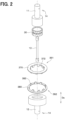
- the torque sensor 25 includes a magnet 30, a rotor 35, a first yoke 361, a second yoke 362 and a fixation collar 354.
- the torque sensor 25 further includes a circuit board 60, a magnetic detector 600, a first magnetic guide member 71, a second magnetic guide member 72, a sensor case 75, a plurality of terminals 80 and a cover 85.
- the magnet 30 is shaped in a circular ring form. Furthermore, the magnet 30 is coupled to an end portion of the first steering shaft 11. A portion of the torsion bar 13 is inserted into a hole of the magnet 30. An axis of the magnet 30 is coaxial with an axis of the torsion bar 13. Therefore, the magnet 30 is rotated together with the first steering shaft 11 about the axis of the torsion bar 13. Furthermore, the magnet 30 is magnetized such that magnetic poles are arranged in the rotational direction of the magnet 30 such that polarities of the magnetic poles are alternately reversed in the rotational direction of the magnet 30.
- the rotor 35 is shaped in a cylindrical tubular form. An axis of the rotor 35 is coaxial with the axis of the magnet 30. Therefore, the axis of the rotor 35, the axis of the magnet 30 and the axis of the torsion bar 13 are coaxial to each other.
- a radial direction of the rotor 35 will be simply referred to as a radial direction.
- an axial direction Da of the rotor 35 will be simply referred to as an axial direction Da.
- a circumferential direction about the axis of the rotor 35 will be simply referred to as a circumferential direction.
- the first yoke 361 is shaped in a tubular form and is made of a soft magnetic material.
- the first yoke 361 has a first-yoke ring 370 and a plurality of first-yoke claws 372.
- the first-yoke ring 370 is shaped in a circular ring form. Furthermore, a plurality of portions of the first-yoke ring 370 are inserted into a plurality of corresponding holes of the rotor 35 each of which extends in the radial direction.
- the first-yoke claws 372 project from an inner periphery of the first-yoke ring 370 in the axial direction Da. Furthermore, each of the first-yoke claws 372 is shaped in a tapered form that is tapered from the inner periphery of the first-yoke ring 370 toward a distal end side of the first-yoke claw 372. Furthermore, each of the first-yoke claws 372 is in contact with and is connected to an inner peripheral surface of the rotor 35. Also, the first-yoke claws 372 are opposed to an outer peripheral surface of the magnet 30 in the radial direction. Furthermore, the plurality of corresponding holes of the rotor 35 are arranged at equal intervals in the circumferential direction, so that the first-yoke claws 372 are also arranged at predetermined intervals in the circumferential direction.
- the second yoke 362 is shaped in a ring form and is made of a soft magnetic material. Furthermore, the second yoke 362 is, for example, integrally molded together with the rotor 35 and the first yoke 361. Furthermore, the second yoke 362 has a second-yoke ring 380 and a plurality of second-yoke claws 382.
- the second-yoke ring 380 is shaped in a circular ring form. Furthermore, a plurality of portions of the second-yoke ring 380 are inserted into a plurality of corresponding holes of the rotor 35 each of which extends in the radial direction.
- the second-yoke claws 382 project from an inner periphery of the second-yoke ring 380 in the axial direction Da. Furthermore, each of the second-yoke claws 382 is shaped in a tapered form that is tapered from the inner periphery of the second-yoke ring 380 toward a distal end side of the second-yoke claw 382. Furthermore, each of the second-yoke claws 382 is in contact with and is connected to the inner peripheral surface of the rotor 35. Also, the second-yoke claws 382 are opposed to the outer peripheral surface of the magnet 30 in the radial direction.
- the plurality of corresponding holes of the rotor 35 are arranged at equal intervals in the circumferential direction, so that the second-yoke claws 382 are also arranged at predetermined intervals in the circumferential direction. Furthermore, each of the second-yoke claws 382 is placed between corresponding adjacent two of the first-yoke claws 372. Therefore, the first-yoke claws 372 and the second-yoke claws 382 are alternately arranged in the circumferential direction. In FIGS. 3 to 6 , the first-yoke claws 372 and the second-yoke claws 382 are partially omitted to avoid complication.
- the fixation collar 354 is shaped in a tubular form.
- the fixation collar 354 is coupled to the inner peripheral surface of the rotor 35. Furthermore, the fixation collar 354 is coupled to the second steering shaft 12. Therefore, the rotor 35 is rotated together with the second steering shaft 12.
- the circuit board 60 is a printed circuit board. Furthermore, the circuit board 60 has a connecting portion 601. This connecting portion 601 is coupled to the magnetic detector 600 described later and is exposed from the sensor case 75 described later.
- the magnetic detector 600 is installed to the circuit board 60 at a location that is adjacent to the second magnetic guide member 72 described later.
- the magnetic detector 600 includes, for example, a Hall element or an MR element (not shown). By using the Hall element or the MR element, the magnetic detector 600 detects a strength of the magnetic field exerted to the magnetic detector 600 in the axial direction Da. Furthermore, the magnetic detector 600 outputs a signal, which corresponds to the detected strength of the magnetic field, to the motor control device 18.
- MR stands for Magneto Resistive.
- the first magnetic guide member 71 is made of a soft magnetic material and is shaped in a plate form that extends in the radial direction. Furthermore, the first magnetic guide member 71 overlaps with the first-yoke ring 370 when the first-yoke ring 370 is projected onto the first magnetic guide member 71 in the axial direction Da. Furthermore, the first magnetic guide member 71 overlaps with the magnetic detector 600 when the first-yoke ring 370 is projected onto the magnetic detector 600 in the axial direction Da.
- the second magnetic guide member 72 is made of a soft magnetic material and is shaped in a plate form that extends in the radial direction. Furthermore, the second magnetic guide member 72 overlaps with the second-yoke ring 380 when the second-yoke ring 380 is projected onto the second magnetic guide member 72 in the axial direction Da. Furthermore, the second magnetic guide member 72 overlaps with the magnetic detector 600 when the second magnetic guide member 72 is projected onto the magnetic detector 600 in the axial direction Da.
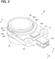
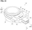
- the sensor case 75 is made of, for example, resin and is shaped in a plate form that extends in the radial direction.
- the sensor case 75 has a first receiving portion 751 and a second receiving portion 752.
- the first receiving portion 751 has a distal end surface 753.
- the distal end surface 753 of the first receiving portion 751 is shaped in an arcuate form. Furthermore, the distal end surface 753 is opposed to a rotor peripheral surface (outer peripheral surface) 350 of the rotor 35 in the radial direction.
- a space 754 is formed between the distal end surface 753 and the rotor peripheral surface 350.
- the first receiving portion 751 is shaped in a bottomed tubular form and thereby receives the magnetic detector 600 and first terminals 81 of the terminals 80 described later. Furthermore, the first receiving portion 751 receives the circuit board 60 such that a portion of the circuit board 60 is exposed from the first receiving portion 751. Furthermore, the first receiving portion 751 has a first base surface 761, a first recess 771, a second base surface 762 and a second recess 772.
- the first base surface 761 is a surface of the first receiving portion 751 which faces one side in the axial direction Da.
- the first recess 771 is a portion that is recessed from the first base surface 761 in the axial direction Da. A portion of the first magnetic guide member 71 is fitted into the first recess 771, and thereby the first magnetic guide member 71 is installed to the sensor case 75.
- the second base surface 762 is a surface of the first receiving portion 751 which faces the other side in the axial direction Da which is opposite to the one side.
- the second recess 772 is a portion that is recessed from the second base surface 762 in the axial direction Da. A portion of the second magnetic guide member 72 is fitted into the second recess 772, and thereby the second magnetic guide member 72 is installed to the sensor case 75.
- the second receiving portion 752 is shaped in a bottomed tubular form. Furthermore, the second receiving portion 752 is joined to the first receiving portion 751 in the radial direction. The second receiving portion 752 receives second terminals 82 of the terminals 80 described later.
- Each of the terminals 80 has the first terminal 81 and the second terminal 82.
- the first terminal 81 extends in the axial direction Da. A portion of the first terminal 81 is inserted into a corresponding one of holes of the circuit board 60. Furthermore, the first terminal 81 is soldered to the circuit board 60 and is thereby connected to the circuit board 60.
- the second terminal 82 is joined to the first terminal 81 and extends in the radial direction. Furthermore, the second terminal 82 is connected to the motor control device 18. Thus, the signal from the magnetic detector 600 is outputted to the motor control device 18 through the corresponding terminal 80.
- the cover 85 is made of, for example, resin. Furthermore, the cover 85 has a sensor cover portion 851 and a rotor cover portion 852.
- the sensor cover portion 851 is joined to a portion of the first base surface 761 by, for example, welding or bonding. Furthermore, the sensor cover portion 851 covers exposed portions of the first magnetic guide member 71, the circuit board 60 and the first terminals 81 which are exposed from the sensor case 75.
- the rotor cover portion 852 is joined to the sensor cover portion 851. Furthermore, the rotor cover portion 852 covers the first-yoke ring 370 in cooperation with the first receiving portion 751 of the sensor case 75. Also, the rotor cover portion 852 is shaped in a circular ring form and has a cover hole 853. A portion of the rotor 35 is inserted into the cover hole 853 in the axial direction Da. Therefore, movement of the rotor 35 in the radial direction is limited. The rotor cover portion 852 is opposed to the first-yoke ring 370 in the axial direction Da. Therefore, movement of the first-yoke ring 370 in the axial direction Da is limited, and movement of the rotor 35 in the axial direction Da is limited.
- a distance, which is measured from a part of the connecting portion 601 where the first-yoke ring 370 and the cover 85 overlap each other in the axial direction Da to a part of the first-yoke ring 370 where the cover 85 and the connecting portion 601 overlap each other in the axial direction Da is defined as a first distance L1.
- a distance, which is measured from the part of the connecting portion 601 where the first-yoke ring 370 and the cover 85 overlap each other in the axial direction Da to a part of the cover 85 where the first-yoke ring 370 and the connecting portion 601 overlap each other in the axial direction Da is defined as a second distance L2.
- the first distance L1 is smaller than the second distance L2.
- the torque sensor 25 is configured in the above-described manner. Next, the detection of the steering torque with the torque sensor 25 will be described.
- each first-yoke claw 372 coincides with a corresponding boundary between the corresponding N-pole and the corresponding S-pole of the magnet 30 in the circumferential direction
- a center of each second-yoke claw 382 coincides with a corresponding boundary between the corresponding N-pole and the corresponding S-pole of the magnet 30 in the circumferential direction.
- the number of magnetic field lines, which extend from the N-pole of the magnet 30 and pass through the first-yoke claw 372 is the same as the number of magnetic field lines, which extend from the N-pole of the magnet 30 and pass through the second-yoke claw 382. Therefore, a magnetic flux density is not generated between the first yoke 361 and the second yoke 362.
- the steering wheel 5 when the steering wheel 5 is rotated, the steering torque is generated. Thereby, the first steering shaft 11, which is coupled to the steering wheel 5, is rotated. Furthermore, the torsion bar 13, which is fixed to the first steering shaft 11 by the shaft pin 14, is rotated. Also, the second steering shaft 12, which is fixed to the torsion bar 13 by the shaft pin 14, is rotated. Furthermore, the second steering shaft 12 is coupled to the fixation collar 354. Therefore, the rotor 35 is rotated. Thereby, the first yoke 361 and the second yoke 362, which are integrally formed with the rotor 35, are rotated relative to the magnet 30.
- an overlapping area between the N-pole of the magnet 30 and the first-yoke claw 372 in the direction perpendicular to the axial direction Da is increased. Furthermore, an overlapping area between the S-pole of the magnet 30 and the second-yoke claw 382 in the direction perpendicular to the axial direction Da is increased.
- the number of magnetic field lines, which extend from the N-pole of the magnet 30 to the first-yoke claw 372, is increased, and the number of magnetic field lines, which extend from the second-yoke claw 382 to the S-pole of the magnet 30, is increased. Therefore, the magnetic flux density is generated between the first yoke 361 and the second yoke 362.
- the first magnetic guide member 71 is made of the soft magnetic material and is opposed to the first-yoke ring 370 and the magnetic detector 600 in the axial direction Da.
- the second magnetic guide member 72 is made of the soft magnetic material and is opposed to the magnetic detector 600 and the second-yoke ring 380 in the axial direction Da.
- the number of magnetic field lines, which extend from the N-pole of the magnet 30 and pass through the magnetic detector 600 via the first-yoke ring 370 and the first magnetic guide member 71, is increased. Furthermore, the magnetic field lines, which have passed through the magnetic detector 600, pass through the S-pole of the magnet 30 via the second magnetic guide member 72 and the second-yoke ring 380.
- the magnetic detector 600 detects the strength of the magnetic field directed toward one side among two opposite sides in the axial direction Da. Thereby, the magnetic detector 600 detects the steering torque. Furthermore, the magnetic detector 600 outputs a signal, which corresponds to the detected strength of the magnetic field, to the motor control device 18 through the corresponding terminal 80. The motor control device 18 calculates the steering torque based on the signal outputted from the magnetic detector 600.
- the number of magnetic field lines, which extend from the N-pole of the magnet 30 and pass through the magnetic detector 600 via the second-yoke ring 380 and the second magnetic guide member 72, is increased. Furthermore, the magnetic field lines, which have passed through the magnetic detector 600, pass through the S-pole of the magnet 30 via the first magnetic guide member 71 and the first-yoke ring 370.
- the magnetic detector 600 detects the strength of the magnetic field directed toward the other side among the two opposite sides in the axial direction Da. Thereby, the magnetic detector 600 detects the steering torque. Furthermore, the magnetic detector 600 outputs the signal, which corresponds to the detected strength of the magnetic field, to the motor control device 18 through the corresponding terminal 80. The motor control device 18 calculates the steering torque based on the signal outputted from the magnetic detector 600.
- the torque sensor 25 detects the steering torque. Next, simplification of a manufacturing process of the torque sensor 25 will be described.
- the torque sensor 25 includes the magnet 30, the rotor 35, the first yoke 361, the second yoke 362, the magnetic detector 600, the sensor case 75 and the cover 85.
- the magnet 30 is configured to generate the magnetic field and is configured to be rotated together with the steering wheel 5.
- the rotor 35 is shaped in a ring form and is configured to be rotated together with the steering wheel 5 about the axis that extends in the axial direction Da.
- the first yoke 361 has the first-yoke ring 370 and the first-yoke claws 372.
- the first-yoke ring 370 is shaped in the ring form and is configured to be rotated together with the rotor 35.
- the first-yoke claws 372 project from the first-yoke ring 370 in the axial direction Da and are thereby opposed to the magnet 30 in the radial direction.
- the first-yoke claws 372 are configured to be rotated together with the first-yoke ring 370 and thereby change the magnetic field generated by the magnet 30.
- the second yoke 362 has the second-yoke ring 380 and the second-yoke claws 382.
- the second-yoke ring 380 is shaped in the ring form and is configured to be rotated together with the rotor 35.
- the second-yoke claws 382 project from the second-yoke ring 380 in the axial direction Da and are thereby opposed to the magnet 30 in the radial direction.
- the second-yoke claws 382 are configured to be rotated together with the second-yoke ring 380 and thereby change the magnetic field generated by the magnet 30.
- the magnetic detector 600 is configured to detect the strength of the magnetic field that changes in response to the rotation of the first-yoke claws 372 and the second-yoke claws 382. This strength of the magnetic field corresponds to the steering torque.
- the sensor case 75 receives the magnetic detector 600.
- the cover 85 has the sensor cover portion 851 and the rotor cover portion 852.
- the sensor cover portion 851 is joined to the first base surface 761.
- the rotor cover portion 852 is joined to the sensor cover portion 851 and receives the rotor 35 inserted in the rotor cover portion 852 in the axial direction Da.
- the rotor cover portion 852 limits movement of the rotor 35 relative to the sensor case 75 in the radial direction.
- the steering wheel 5 serves as a detection subject (detection subject device).
- the steering torque serves as the torque of the detection subject.
- the first yoke 361 and the second yoke 362 each serve as a yoke.
- the first-yoke ring 370 and the second-yoke ring 380 each serve as a ring.
- the first-yoke claws 372 serve as a plurality of claws, and the second-yoke claws 382 also serve as a plurality of claws.
- the radial direction serves as a direction perpendicular to the axial direction Da.
- the rotor 35 is inserted into the rotor cover portion 852 in the axial direction Da, and the rotor cover portion 852 is joined to the sensor cover portion 851. Therefore, movement of the rotor 35 relative to the sensor case 75 in the radial direction is limited.
- the torque sensor 25 is assembled by inserting the components in the axial direction Da only, which simplifies the manufacturing process in comparison to the case where the torque sensor is assembled by inserting the components in the two directions, i.e., the axial direction Da and the radial direction.
- the movement of the first-yoke ring 370 in the axial direction Da is limited, it is possible to limit variations in the distance in the axial direction Da between: the first-yoke ring 370; and the first magnetic guide member 71 that is opposed to the first-yoke ring 370 in the axial direction Da.
- variations in the sensitivity of the magnetic detector 600 are limited.
- the torque sensor 25 includes the circuit board 60.
- the magnetic detector 600 is installed on the circuit board 60 while the circuit board 60 is received in the sensor case 75. Furthermore, the circuit board 60 has the connecting portion 601. The connecting portion 601 is coupled to the magnetic detector 600 and is exposed from the sensor case 75.
- the sensor cover portion 851 covers the connecting portion 601.
- the magnetic detector 600 and the other components, which are installed on the circuit board 60, are protected from foreign objects, and thereby the dustproof and waterproof performance of the torque sensor 25 is improved.
- the first distance L1 is smaller than the second distance L2.
- the first distance L1 corresponds to the distance, which is measured from the part of the connecting portion 601 where the first-yoke ring 370 and the cover 85 overlap each other in the axial direction Da to the part of the first-yoke ring 370 where the cover 85 and the connecting portion 601 overlap each other in the axial direction Da.
- the second distance L2 corresponds to the distance, which is measured from the part of the connecting portion 601 where the first-yoke ring 370 and the cover 85 overlap each other in the axial direction Da to the part of the cover 85 where the first-yoke ring 370 and the connecting portion 601 overlap each other in the axial direction Da.
- a distance between the first-yoke ring 370 and the connecting portion 601 is increased by the amount that corresponds to the size of the sensor cover portion 851.
- the first distance L1 is smaller than the second distance L2
- the first-yoke ring 370 is positioned between the sensor cover portion 851 and the connecting portion 601. Therefore, since the sensor cover portion 851 is not positioned between the first-yoke ring 370 and the connecting portion 601, the distance between the first-yoke ring 370 and the connecting portion 601 can be reduced by the amount that corresponds to the size of the sensor cover portion 851. This limits the attenuation of the magnetic field passing through the magnetic detector 600 from the first-yoke ring 370, and thereby the sensitivity of the magnetic detector 600 is improved.
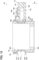
- the configurations of the sensor case 75 and the cover 85 are different from those of the first embodiment.
- the rest of the present embodiment is the same as that of the first embodiment.
- the first-yoke claws 372 and the second-yoke claws 382 are partially omitted to avoid complication.
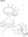
- the sensor case 75 has a plurality of cover retainer pins 758. Each of the cover retainer pins 758 projects from the first base surface 761 in the axial direction Da.
- the sensor cover portion 851 of the cover 85 has a plurality of pin receiving holes 854. A portion of each of the cover retainer pins 758 is inserted into a corresponding one of the pin receiving holes 854. This makes it difficult for the cover 85 to come off the sensor case 75.
- the sensor cover portion 851 and the cover retainer pins 758 are coupled together by, for example, heat-caulking, so that it makes more difficult for the cover 85 to come off the sensor case 75 than in a case where the sensor cover portion 851 and the cover retainer pins 758 are not coupled together by, for example, the heat-caulking.
- the sensor cover portion 851 may have the cover retainer pins 758, and the pin receiving holes 854 may be formed at the first base surface 761 of the sensor case 75.
- the second embodiment is configured in the above-described manner. Even in the second embodiment, the advantages, which are similar to those of the first embodiment, are achieved.
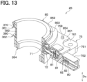
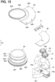
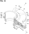
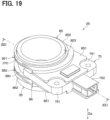
- the configurations of the sensor case 75, the circuit board 60 and the cover 85 are different from those of the first embodiment. Furthermore, the configuration of the rotor 35 is different from that of the first embodiment. Furthermore, the torque sensor 25 includes a first follower rotor 31, a second follower rotor 32, a first angle-detection magnetic guide member 711, a first angle-detection magnet 51, a second angle-detection magnetic guide member 722, a second angle-detection magnet 52, a first magnetic angle detector 611 and a second magnetic angle detector 622. The rest of the present embodiment is the same as that of the first embodiment. In FIGS. 14 to 18 , the first-yoke claws 372 and the second-yoke claws 382 are partially omitted to avoid complication.
- the sensor case 75 is shaped in an arcuate form. Therefore, the circuit board 60, which is configured to be received in the sensor case 75, is shaped in an arcuate form.
- the sensor case 75 has the cover retainer pins 758 described above.
- the sensor cover portion 851 is shaped in an arcuate form.
- the sensor cover portion 851 of the cover 85 has the pin receiving holes 854 described above.
- the rotor 35 includes a gear arrangement 355.
- the gear arrangement 355 includes a circular ring 356 and a plurality of rotor gear teeth 357.
- the circular ring 356 is shaped in a circular ring form.
- the rotor gear teeth 357 project from the circular ring 356 in the axial direction Da.
- the first follower rotor 31 is made of, for example, resin.
- the first follower rotor 31 is received in the first receiving portion 751 of the sensor case 75. Furthermore, the first follower rotor 31 is covered by the first receiving portion 751 and the sensor cover portion 851. An axis of the first follower rotor 31 is parallel to the axis of the rotor 35.
- the first follower rotor 31 includes a first cylindrical tubular portion 313 and a plurality of first follower gear teeth 314.
- the first cylindrical tubular portion 313 is shaped in a cylindrical tubular form.
- Each of the first follower gear teeth 314 outwardly projects from the first cylindrical tubular portion 313 in the radial direction. Furthermore, a portion of each of the first follower gear teeth 314 is configured to be placed between corresponding adjacent two of the rotor gear teeth 357. Therefore, the first follower rotor 31 is meshed with the rotor 35.
- the number of the first follower gear teeth 314, which is the number of the teeth of the first follower rotor 31, is different from the number of the rotor gear teeth 357, which is the number of the teeth of the rotor 35.
- the second follower rotor 32 is made of, for example, resin.
- the second follower rotor 32 is received in the first receiving portion 751 of the sensor case 75. Furthermore, the second follower rotor 32 is covered by the first receiving portion 751 and the sensor cover portion 851. Furthermore, an axis of the second follower rotor 32 is parallel to the axis of the rotor 35 and the axis of the first follower rotor 31.
- the second follower rotor 32 includes a second cylindrical tubular portion 323 and a plurality of second follower gear teeth 324.
- the second cylindrical tubular portion 323 is shaped in a cylindrical tubular form.
- Each of the second follower gear teeth 324 outwardly projects from the second cylindrical tubular portion 323 in the radial direction. Furthermore, a portion of each of the second follower gear teeth 324 is configured to be placed between corresponding adjacent two of the rotor gear teeth 357. Therefore, the second follower rotor 32 is meshed with the rotor 35.
- the number of the second follower gear teeth 324 which is the number of the teeth of the second follower rotor 32, is different from the number of the rotor gear teeth 357, which is the number of the teeth of the rotor 35.
- the first angle-detection magnetic guide member 711 is installed to the first cylindrical tubular portion 313.
- the first angle-detection magnetic guide member 711 is configured to guide a magnetic field, which is generated by the first angle-detection magnet 51 described later, to the first magnetic angle detector 611 described later.
- the first angle-detection magnet 51 is inserted into the first cylindrical tubular portion 313. Therefore, when the first follower rotor 31 is rotated, the first angle-detection magnet 51 is rotated together with the first follower rotor 31. Furthermore, the first angle-detection magnet 51 is opposed to the first angle-detection magnetic guide member 711 in the axial direction Da and also a direction perpendicular to the axial direction Da. Also, in an initial state where the steering wheel 5 is not rotated, one side of the first angle-detection magnet 51 in a first direction D1 is magnetized to, for example, an N-pole.
- the other side of the first angle-detection magnet 51 in the first direction D1 is magnetized to, for example, an S-pole.
- the first direction D1 is a direction along a straight line that connects between the axis of the rotor 35 and the axis of the first follower rotor 31 and is perpendicular to the axial direction Da.
- the second angle-detection magnetic guide member 722 is installed to the second cylindrical tubular portion 323. Furthermore, the second angle-detection magnetic guide member 722 is configured to guide a magnetic field, which is generated by the second angle-detection magnet 52 described later, to the second magnetic angle detector 622 described later.
- the second angle-detection magnet 52 is inserted into the second cylindrical tubular portion 323. Therefore, when the second follower rotor 32 is rotated, the second angle-detection magnet 52 is rotated together with the second follower rotor 32. Furthermore, the second angle-detection magnet 52 is opposed to the second angle-detection magnetic guide member 722 in the axial direction Da and also the direction perpendicular to the axial direction Da. Also, in the initial state where the steering wheel 5 is not rotated, one side of the second angle-detection magnet 52 in a second direction D2 is magnetized to, for example, an N-pole.
- the other side of the second angle-detection magnet 52 in the second direction D2 is magnetized to, for example, an S-pole.
- the second direction D2 is a direction along a straight line that connects between the axis of the rotor 35 and the axis of the second follower rotor 32 and is perpendicular to the axial direction Da.
- the first magnetic angle detector 611 is installed to the circuit board 60. Furthermore, the first magnetic angle detector 611 is opposed to the first angle-detection magnetic guide member 711 in the axial direction Da. Therefore, the magnetic field lines, which extend from the N-pole of the first angle-detection magnet 51, pass through the first magnetic angle detector 611 via the first angle-detection magnetic guide member 711. Furthermore, the first magnetic angle detector 611 includes a first element and a second element (not shown). The first element and the second element are, for example, Hall elements or MR elements. Furthermore, the first element of the first magnetic angle detector 611 detects the strength of the magnetic field in one direction among the magnetic fields, which pass through the first magnetic angle detector 611.
- the second element of the first magnetic angle detector 611 detects the strength of the magnetic field in a direction perpendicular to the direction of the magnetic field detected by the first element of the first magnetic angle detector 611. Furthermore, the first magnetic angle detector 611 outputs signals, which respectively correspond to these detected strengths of the magnetic fields, to the motor control device 18 through the corresponding terminals 80.
- the second magnetic angle detector 622 is installed to the circuit board 60. Furthermore, the second magnetic angle detector 622 is opposed to the second angle-detection magnetic guide member 722 in the axial direction Da. Therefore, the magnetic field lines, which extend from the N-pole of the second angle-detection magnet 52, pass through the second magnetic angle detector 622 via the second angle-detection magnetic guide member 722. Furthermore, the second magnetic angle detector 622 includes a first element and a second element (not shown). The first element and the second element are, for example, Hall elements or MR elements. Furthermore, the first element of the second magnetic angle detector 622 detects the strength of the magnetic field in one direction among the magnetic fields, which pass through the second magnetic angle detector 622.
- the second element of the second magnetic angle detector 622 detects the strength of the magnetic field in a direction perpendicular to the direction of the magnetic field detected by the first element of the second magnetic angle detector 622. Furthermore, the second magnetic angle detector 622 outputs signals, which respectively correspond to these detected strengths of the magnetic fields, to the motor control device 18 through the corresponding terminals 80.
- the third embodiment is configured in the above-described manner.
- the torque sensor 25 detects the steering angle of the steering wheel 5 in addition to the steering torque. Next, the detection of the steering angle with the torque sensor 25 will be described.
- the steering wheel 5 When the steering wheel 5 is rotated, the steering torque is generated. Thereby, the first steering shaft 11, which is coupled to the steering wheel 5, is rotated. Furthermore, the torsion bar 13, which is fixed to the first steering shaft 11 by the shaft pin 14, is rotated. Also, the second steering shaft 12, which is fixed to the torsion bar 13 by the shaft pin 14, is rotated. Furthermore, the second steering shaft 12 is coupled to the fixation collar 354 of the rotor 35. Therefore, the rotor 35 is rotated. Thus, the first follower rotor 31 and the second follower rotor 32, which are meshed with the rotor 35, are rotated.
- the first angle-detection magnet 51 which is installed to the first follower rotor 31, is rotated. Therefore, the magnetic field lines, which extend from the N-pole of the first angle-detection magnet 51 and pass through the first angle-detection magnetic guide member 711, the first magnetic angle detector 611, the first angle-detection magnetic guide member 711 and the S-pole of the first angle-detection magnet 51, periodically change. Thus, the strength of the magnetic field in the one direction applied to the first magnetic angle detector 611 periodically changes.
- the one side of the first angle-detection magnet 51 in the first direction D1 is magnetized to the N-pole. Furthermore, in the initial state where the steering wheel 5 is not rotated, the other side of the first angle-detection magnet 51 in the first direction D1 is magnetized to the S-pole. Therefore, in the initial state where the steering wheel 5 is not rotated, the strength of the magnetic field in the first direction D1 applied to the first magnetic angle detector 611 becomes a predetermined value.
- an output waveform of the first element of the first magnetic angle detector 611 which detects the strength of the magnetic field in the first direction D1 becomes a cosine waveform. Therefore, at this time, the first element of the first magnetic angle detector 611 outputs the signal, which forms the cosine waveform corresponding to the rotational angle of the first follower rotor 31 and the steering angle, to the motor control device 18. Furthermore, when the steering angle changes, an output waveform of the second element of the first magnetic angle detector 611, which detects the strength of the magnetic field in the direction perpendicular to the first direction D1, becomes a sine waveform. Therefore, at this time, the second element of the first magnetic angle detector 611 outputs the signal, which forms the sine waveform corresponding to the rotational angle of the first follower rotor 31 and the steering angle, to the motor control device 18.
- the second angle-detection magnet 52 which is installed to the second follower rotor 32, is rotated. Therefore, the magnetic field lines, which extend from the N-pole of the second angle-detection magnet 52 and pass through the second angle-detection magnetic guide member 722, the second magnetic angle detector 622, the second angle-detection magnetic guide member 722 and the S-pole of the second angle-detection magnet 52, periodically change. Thus, the strength of the magnetic field in the second direction D2 applied to the second magnetic angle detector 622 periodically changes.
- the one side of the second angle-detection magnet 52 in the second direction D2 is magnetized to the N-pole. Furthermore, in the initial state where the steering wheel 5 is not rotated, the other side of the second angle-detection magnet 52 in the second direction D2 is magnetized to the S-pole. Therefore, in the initial state where the steering wheel 5 is not rotated, the strength of the magnetic field in the second direction D2 applied to the second magnetic angle detector 622 becomes a predetermined value.
- an output waveform of the first element of the second magnetic angle detector 622 which detects the strength of the magnetic field in the second direction D2 becomes a cosine waveform. Therefore, at this time, the first element of the second magnetic angle detector 622 outputs the signal, which forms the cosine waveform corresponding to the rotational angle of the second follower rotor 32 and the steering angle, to the motor control device 18. Furthermore, when the steering angle changes, an output waveform of the second element of the second magnetic angle detector 622, which detects the strength of the magnetic field in the direction perpendicular to the second direction D2, becomes a sine waveform. Therefore, at this time, the second element of the second magnetic angle detector 622 outputs the signal, which forms the sine waveform corresponding to the rotational angle of the second follower rotor 32 and the steering angle, to the motor control device 18.
- the motor control device 18 calculates a value, which relates to the steering angle, based on the signals outputted from the first and second elements of the first magnetic angle detector 611 and the signals outputted from the first and second elements of the second magnetic angle detector 622.
- the motor control device 18 divides a value of the signal, which is outputted from the second element of the first magnetic angle detector 611 and forms the sine waveform, by a value of the signal, which is outputted from the first element of the first magnetic angle detector 611 and forms the cosine waveform. Thereby, the motor control device 18 calculates a value of a tangent, which corresponds to the rotational angle of the first follower rotor 31, thereby calculating the rotational angle of the first follower rotor 31.
- the motor control device 18 divides a value of the signal, which is outputted from the second element of the second magnetic angle detector 622 and forms the sine waveform, by a value of the signal, which is outputted from the first element of the second magnetic angle detector 622 and forms the cosine waveform. Thereby, the motor control device 18 calculates a value of a tangent, which corresponds to the rotational angle of the second follower rotor 32, thereby calculating the rotational angle of the second follower rotor 32.
- the number of the second follower gear teeth 324 which is the number of the teeth of the second follower rotor 32, is different from the number of the first follower gear teeth 314, which is the number of the teeth of the first follower rotor 31. Therefore, periods of the output waveforms of the first and second elements of the first magnetic angle detector 611 are different from the periods of the output waveforms of the first and second elements of the second magnetic angle detector 622. Furthermore, the outputs of the first and second elements of the first magnetic angle detector 611 and the outputs of the first and second elements of the second magnetic angle detector 622 respectively correspond to the steering angle. Therefore, a difference between the rotational angle of the first follower rotor 31 and the rotational angle of the second follower rotor 32 corresponds to the steering angle.
- the motor control device 18 calculates the difference between the rotational angle of the first follower rotor 31 and the rotational angle of the second follower rotor 32 and calculates the steering angle based on this calculated difference.
- the torque sensor 25 detects the steering angle in the above-described manner. Even in the third embodiment, the advantages, which are similar to those of the first embodiment, are achieved. Furthermore, in the third embodiment, the following advantage is also achieved.
- the torque sensor 25 includes the first follower rotor 31, the second follower rotor 32, the first angle-detection magnet 51, the second angle-detection magnet 52, the first magnetic angle detector 611 and the second magnetic angle detector 622.
- the first follower rotor 31 and the second follower rotor 32 are configured to rotate together with the rotor 35.
- the first angle-detection magnet 51 is configured to generate the magnetic field and is configured to be rotated together with the first follower rotor 31.
- the second angle-detection magnet 52 is configured to generate the magnetic field and is configured to be rotated together with the second follower rotor 32.
- the first magnetic angle detector 611 is configured to detect the strength of the magnetic field that changes in response to the rotation of the first follower rotor 31 and corresponds to the steering angle.
- the second magnetic angle detector 622 is configured to detect the strength of the magnetic field that changes in response to the rotation of the second follower rotor 32 and corresponds to the steering angle.
- the first angle-detection magnet 51 and the second angle-detection magnet 52 each serve as an angle-detection magnet.
- the first magnetic angle detector 611 and the second magnetic angle detector 622 each serve as an angle detector.
- the steering angle serves as a rotational angle of the detection subject.
- the torque sensor 25 can detect the steering angle in addition to the steering torque.
- the torque sensor 25 functions as a torque angle sensor.
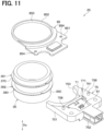
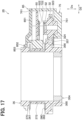
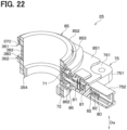
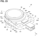
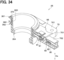
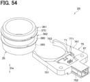
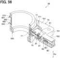
- the torque sensor 25 includes a first cover 85 and a second cover 86.
- the rest of the present embodiment is the same as that of the first embodiment.
- the first-yoke claws 372 and the second-yoke claws 382 are partially omitted to avoid complication.
- the first cover 85 corresponds to the cover 85 described above.
- the second cover 86 is made of, for example, resin. Furthermore, the second cover 86 includes a second sensor cover portion 861 and a second rotor cover portion 862.
- the second sensor cover portion 861 is joined to a portion of the second base surface 762 by, for example, welding or bonding.
- the second sensor cover portion 861 covers the second magnetic guide member 72 and the magnetic detector 600 which are exposed to the outside.
- the second rotor cover portion 862 is joined to the second sensor cover portion 861. Also, the second rotor cover portion 862 is shaped in a circular ring form and has a second cover hole 863. The second cover hole 863 is shaped in a circular form. Thus, a portion of the rotor 35 is inserted into the second cover hole 863 in the axial direction Da.
- the torque sensor 25 is configured in the above-described manner. Even in the fourth embodiment, the advantages, which are similar to those of the first embodiment, are achieved.
- the configurations of the sensor case 75 and the cover 85 are different from those of the fourth embodiment.
- the rest of the present embodiment is the same as that of the fourth embodiment.
- the first-yoke claws 372 and the second-yoke claws 382 are partially omitted to avoid complication.
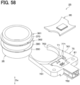
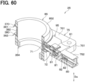
- the sensor case 75 has a plurality of first-side pins 791 and a plurality of second-side pins 792.
- Each of the first-side pins 791 projects from the first base surface 761 in the axial direction Da.
- Each of the second-side pins 792 projects from the second base surface 762 in the axial direction Da.
- the sensor cover portion 851 of the cover 85 has a plurality of first-side pin receiving holes 854.
- the first-side pin receiving holes 854 correspond to the pin receiving holes 854 described above.
- a portion of each of the first-side pins 791 is inserted into a corresponding one of the first-side pin receiving holes 854. This makes it difficult for the cover 85 to come off the sensor case 75.
- the sensor cover portion 851 and the first-side pins 791 are coupled together by, for example, heat-caulking, so that it makes more difficult for the cover 85 to come off the sensor case 75 than in the case where the sensor cover portion 851 and the first-side pins 791 are not coupled together by, for example, the heat-caulking.
- the sensor cover portion 851 may have the first-side pins 791, and the first-side pin receiving holes 854 may be formed at the first base surface 761 of the sensor case 75.
- the second sensor cover portion 861 of the second cover 86 has a plurality of second-side pin receiving holes 855. A portion of each of the second-side pins 792 is inserted into a corresponding one of the second-side pin receiving holes 855. This makes it difficult for the second cover 86 to come off the sensor case 75.
- the second sensor cover portion 861 and the second-side pins 792 are coupled together by, for example, heat-caulking, so that it makes more difficult for the second cover 86 to come off the sensor case 75 than in the case where the second sensor cover portion 861 and the second-side pins 792 are not coupled together by, for example, the heat-caulking.
- the second sensor cover portion 861 may have the second-side pins 792, and the second-side pin receiving holes 855 may be formed at the second base surface 762 of the sensor case 75.
- the fifth embodiment is configured in the above-described manner. Even in the fifth embodiment, the advantages, which are similar to those of the fourth embodiment, are achieved.
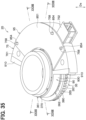
- the configuration of the sensor case 75 is different from that of the first embodiment.
- the torque sensor 25 includes two magnetic detectors 600 and a holder member 90 but does not include the first magnetic guide member 71, the second magnetic guide member 72 and the cover 85.
- the rest of the present embodiment is the same as that of the first embodiment.
- the first-yoke claws 372 and the second-yoke claws 382 are partially omitted to avoid complication.
- the sensor case 75 has a case peripheral surface (case outer peripheral surface) 781 and two guide surfaces 782.
- the case peripheral surface 781 is joined to the first base surface 761 and extends in the axial direction Da from a boundary between the case peripheral surface 781 and the first base surface 761.
- Each of the guide surfaces 782 is joined to an opposite side of the case peripheral surface 781 which is opposite to the first base surface 761, and each of the guide surfaces 782 extends in the radial direction from a boundary between the guide surface 782 and the case peripheral surface 781.
- the torque sensor 25 includes the two magnetic detectors 600. Therefore, if one of the magnetic detectors 600 fails, the torque sensor 25 can detect the steering torque by using the other one of the magnetic detectors 600.
- the holder member 90 is shaped in a U-shape form. Furthermore, the holder member 90 has a curved portion 900 and two straight portions 910.
- the curved portion 900 is shaped in an arcuate form. Furthermore, the curved portion 900 is opposed to the rotor peripheral surface 350 in the radial direction. A space is formed between the curved portion 900 and the rotor peripheral surface 350.
- the curved portion 900 is placed between the first-yoke ring 370 and the second-yoke ring 380 in the axial direction Da. Therefore, the curved portion 900 is opposed to the first-yoke ring 370 and the second-yoke ring 380 in the axial direction Da. Thus, movement of each of the first-yoke ring 370 and the second-yoke ring 380 in the axial direction Da is limited.
- the straight portions 910 are joined to the curved portion 900 and extend from the curved portion 900 in the radial direction. Furthermore, each of the straight portions 910 is joined to the case peripheral surface 781 and the corresponding guide surface 782 by, for example, welding or bonding. Therefore, the rotor 35 is surrounded by the holder member 90 and the sensor case 75 in the radial direction. Thus, movement of the rotor 35 in the radial direction is limited.
- the torque sensor 25 is configured in the above-described manner. Next, even in the sixth embodiment, the simplification of the manufacturing process of the torque sensor 25 will be described.
- the torque sensor 25 includes the magnet 30, the rotor 35, the first yoke 361, the second yoke 362, the magnetic detectors 600, the sensor case 75 and the holder member 90.
- the magnet 30 is configured to generate the magnetic field and is configured to be rotated together with the steering wheel 5.
- the rotor 35 is shaped in the ring form and is configured to be rotated together with the steering wheel 5 about an axis that extends in the axial direction Da.
- the first yoke 361 has the first-yoke ring 370 and the first-yoke claws 372.
- the first-yoke ring 370 is shaped in the ring form and is configured to be rotated together with the rotor 35.
- the first-yoke claws 372 project from the first-yoke ring 370 in the axial direction Da and are thereby opposed to the magnet 30 in the radial direction.
- the first-yoke claws 372 are configured to be rotated together with the first-yoke ring 370 and thereby change the magnetic field generated by the magnet 30.
- the second yoke 362 has the second-yoke ring 380 and the second-yoke claws 382.
- the second-yoke ring 380 is shaped in the ring form and is configured to be rotated together with the rotor 35.
- the second-yoke claws 382 project from the second-yoke ring 380 in the axial direction Da and are thereby opposed to the magnet 30 in the radial direction.
- the second-yoke claws 382 are configured to be rotated together with the second-yoke ring 380 and thereby change the magnetic field generated by the magnet 30.
- Each of the magnetic detectors 600 is configured to detect the strength of the magnetic field that changes in response to the rotation of the first-yoke claws 372 and the second-yoke claws 382. This strength of the magnetic field corresponds to the steering torque.
- the sensor case 75 receives the magnetic detectors 600.
- the holder member 90 surrounds the sensor case 75 and the rotor 35 in the radial direction, so that the holder member 90 limits movement of the rotor 35 relative to the sensor case 75 in the radial direction.
- the torque sensor 25 for example, by moving the holder member 90 only in the radial direction, the holder member 90 surrounds the rotor 35 in cooperation with the sensor case 75. Therefore, movement of the rotor 35 relative to the sensor case 75 in the radial direction is limited.
- the torque sensor 25 is assembled by moving the components only in the one direction, the manufacturing process is simplified in comparison to the case where the torque sensor is assembled by inserting the components in the two directions, i.e., the axial direction Da and the radial direction.
- the movement of the first-yoke ring 370 in the axial direction Da is limited, it is possible to limit variations in the distance in the axial direction Da between: the first-yoke ring 370; and the first magnetic guide member 71 that is opposed to the first-yoke ring 370 in the axial direction Da.
- variations in the sensitivity of the magnetic detector 600 are limited.
- the torque sensor 25 further includes a sensor cover 95.
- the rest of the present embodiment is the same as that of the sixth embodiment.
- the first-yoke claws 372 and the second-yoke claws 382 are partially omitted to avoid complication.
- the sensor cover 95 covers an exposed portion of the circuit board 60, which is exposed from the sensor case 75, in cooperation with the first receiving portion 751 of the sensor case 75. Therefore, the magnetic detector 600 and the other components, which are installed on the circuit board 60, are protected from the foreign objects, and thereby the dustproof and waterproof performance of the torque sensor 25 is improved.
- the seventh embodiment is configured in the above-described manner. Even in the seventh embodiment, the advantages, which are similar to those of the sixth embodiment, are achieved.
- the configurations of the sensor case 75, the circuit board 60, the sensor cover 95 and the holder member 90 are different from those of the seventh embodiment. Furthermore, the configuration of the rotor 35 is different from that of the first embodiment.
- the torque sensor 25 includes the first follower rotor 31, the second follower rotor 32, the first angle-detection magnetic guide member 711, the first angle-detection magnet 51, the second angle-detection magnetic guide member 722, the second angle-detection magnet 52, the first magnetic angle detector 611 and the second magnetic angle detector 622.
- the rest of the present embodiment is the same as that of the sixth embodiment.
- the first-yoke claws 372 and the second-yoke claws 382 are partially omitted to avoid complication.
- the sensor case 75 is shaped in an arcuate form. Therefore, the circuit board 60, which is configured to be received in the sensor case 75, is shaped in an arcuate form.
- the sensor case 75 has the cover retainer pins 758 described above.
- the sensor cover 95 has the pin receiving holes 854 described above.
- the holder member 90 has the curved portion 900 and the straight portions 910.
- the curved portion 900 is shaped in an arcuate form.
- the curved portion 900 is placed between the first-yoke ring 370 and the second-yoke ring 380 in the axial direction Da. Furthermore, a space is formed between the curved portion 900 and each of the first-yoke ring 370 and the second-yoke ring 380.
- the curved portion 900 is opposed to the rotor peripheral surface 350 in the radial direction. A space is formed between the curved portion 900 and the rotor peripheral surface 350.
- the straight portions 910 are joined to the curved portion 900 and extend from the curved portion 900 in the radial direction. Furthermore, each of the straight portions 910 is joined to the case peripheral surface 781 by, for example, welding or bonding. Therefore, the rotor 35 is surrounded by the holder member 90 and the sensor case 75 in the radial direction.
- the rotor 35 is formed in the same way as in the third embodiment.
- the first follower rotor 31, the second follower rotor 32, the first angle-detection magnetic guide member 711 and the first angle-detection magnet 51 are formed in the same manner as in the third embodiment but are covered by the first receiving portion 751 and the sensor cover 95 unlike the third embodiment.
- the second angle-detection magnetic guide member 722, the second angle-detection magnet 52, the first magnetic angle detector 611 and the second magnetic angle detector 622 are formed in the same manner as in the third embodiment but are covered by the first receiving portion 751 and the sensor cover 95 unlike the third embodiment.
- the eighth embodiment is configured in the above-described manner. Even in the eighth embodiment, the advantages, which are similar to those of the seventh embodiment, are achieved. Furthermore, in the eighth embodiment, the steering angle can be detected in addition to the steering torque.
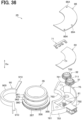
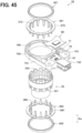
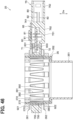
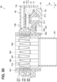
- the configuration of the rotor 35 is different from that of the first embodiment. Furthermore, the configuration of the sensor case 75 is different. Also, the torque sensor 25 does not include the first magnetic guide member 71, the second magnetic guide member 72, the fixation collar 354 and the cover 85. Furthermore, the torque sensor 25 includes two magnetic detectors 600. Additionally, the torque sensor 25 includes a first fixation member 921 and a second fixation member 922. The rest of the present embodiment is the same as that of the first embodiment.
- the rotor 35 includes a tubular portion 351 and a yoke holding portion 352.
- the tubular portion 351 is shaped in a cylindrical tubular form.
- the yoke holding portion 352 has a plurality of first-yoke recesses 391 and a plurality of second-yoke recesses 392.
- Each of the first-yoke recesses 391 has a shape that corresponds to a corresponding one of the first-yoke claws 372. Therefore, the first-yoke claws 372 are respectively inserted into the first-yoke recesses 391, and thereby the yoke holding portion 352 holds the first yoke 361.
- Each of the second-yoke recesses 392 has a shape that corresponds to a corresponding one of the second-yoke claws 382. Therefore, the second-yoke claws 382 are respectively inserted into the second-yoke recesses 392, and thereby the yoke holding portion 352 holds the second yoke 362.
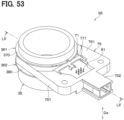
- the sensor case 75 has a limiting portion 755 in addition to the first receiving portion 751 and the second receiving portion 752.
- the limiting portion 755 is joined to the first receiving portion 751. Also, the limiting portion 755 is shaped in a circular ring form and has a rotor receiving hole 756. A part of the yoke holding portion 352 is inserted into the rotor receiving hole 756 in the axial direction Da. Therefore, movement of the rotor 35 in the radial direction is limited. Furthermore, the limiting portion 755 is positioned between the first-yoke ring 370 and the second-yoke ring 380 in the axial direction Da and is opposed to the first-yoke ring 370 and the second-yoke ring 380 in the axial direction Da. Thus, movement of each of the first-yoke ring 370 and the second-yoke ring 380 in the axial direction Da is limited.
- the first fixation member 921 is shaped in a circular ring form. Furthermore, the first fixation member 921 clamps the first-yoke ring 370 between the first fixation member 921 and the yoke holding portion 352 in the axial direction Da. Therefore, removal of the first yoke 361 from the yoke holding portion 352 is limited.
- the second fixation member 922 is shaped in a circular ring form. Furthermore, the second fixation member 922 clamps the second-yoke ring 380 between the second fixation member 922 and the yoke holding portion 352 in the axial direction Da. Therefore, removal of the second yoke 362 from the yoke holding portion 352 is limited.
- the torque sensor 25 is configured in the above-described manner. Next, even in the ninth embodiment, the simplification of the manufacturing process of the torque sensor 25 will be described.
- the torque sensor 25 includes the magnet 30, the rotor 35, the first yoke 361, the second yoke 362, the magnetic detectors 600 and the sensor case 75.
- the magnet 30 is configured to generate the magnetic field and is configured to be rotated together with the steering wheel 5.
- the rotor 35 is shaped in the ring form and is configured to be rotated together with the steering wheel 5 about the axis that extends in the axial direction Da.
- the first yoke 361 has the first-yoke ring 370 and the first-yoke claws 372.
- the first-yoke ring 370 is shaped in the ring form and is configured to be rotated together with the rotor 35.
- the first-yoke claws 372 project from the first-yoke ring 370 in the axial direction Da and are thereby opposed to the magnet 30 in the radial direction.
- the first-yoke claws 372 are configured to be rotated together with the first-yoke ring 370 and thereby change the magnetic field generated by the magnet 30.
- the second yoke 362 has the second-yoke ring 380 and the second-yoke claws 382.
- the second-yoke ring 380 is shaped in the ring form and is configured to be rotated together with the rotor 35.
- the second-yoke claws 382 project from the second-yoke ring 380 in the axial direction Da and are thereby opposed to the magnet 30 in the radial direction.
- the second-yoke claws 382 are configured to be rotated together with the second-yoke ring 380 and thereby change the magnetic field generated by the magnet 30.
- Each of the magnetic detectors 600 is configured to detect the strength of the magnetic field that changes in response to the rotation of the first-yoke claws 372 and the second-yoke claws 382. This strength of the magnetic field corresponds to the steering torque.
- the sensor case 75 includes the limiting portion 755 and the first receiving portion 751.
- the limiting portion 755 is shaped in the ring form.
- the rotor 35 is inserted into the limiting portion 755 in the axial direction Da.
- the first receiving portion 751 is joined to the limiting portion 755 and receives the magnetic detectors 600.
- the limiting portion 755 limits movement of the rotor 35 relative to the sensor case 75 in the radial direction.
- the rotor 35 is inserted into the limiting portion 755 in the axial direction Da, and the limiting portion 755 is joined to the first receiving portion 751. Therefore, movement of the rotor 35 relative to the sensor case 75 in the radial direction is limited.
- the torque sensor 25 is assembled by inserting the components in the axial direction Da only, which simplifies the manufacturing process in comparison to the case where the torque sensor is assembled by inserting the components in the two directions, i.e., the axial direction Da and the radial direction.
- the limiting portion 755 is opposed to the first-yoke ring 370 in the axial direction Da and thereby limits the movement of the first-yoke ring 370 relative to the sensor case 75 in the axial direction Da.
- the movement of the first-yoke ring 370 in the axial direction Da is limited, it is possible to limit variations in the distance in the axial direction Da between: the first-yoke ring 370; and the first magnetic guide member 71 that is opposed to the first-yoke ring 370 in the axial direction Da.
- variations in the sensitivity of the magnetic detector 600 are limited.
- the torque sensor 25 further includes the first magnetic guide member 71, the second magnetic guide member 72 and the sensor cover 95.
- the rest of the present embodiment is the same as that of the ninth embodiment.
- the first magnetic guide member 71 and the second magnetic guide member 72 are formed in the same way as in the first embodiment described above.
- the sensor cover 95 covers an exposed portion of the circuit board 60, which is exposed from the sensor case 75, in cooperation with the first receiving portion 751 of the sensor case 75. Therefore, the magnetic detector 600 and the other components, which are installed on the circuit board 60, are protected from the foreign objects, and thereby the dustproof and waterproof performance of the torque sensor 25 is improved.
- the tenth embodiment is configured in the above-described manner. Even in the tenth embodiment, the advantages, which are similar to those of the ninth embodiment, are achieved.
- the configurations of the sensor case 75, the circuit board 60 and the sensor cover 95 are different from those of the tenth embodiment.
- the configuration of the rotor 35 is different from that of the first embodiment.
- the torque sensor 25 includes the first follower rotor 31, the second follower rotor 32, the first angle-detection magnetic guide member 711, the first angle-detection magnet 51, the second angle-detection magnetic guide member 722, the second angle-detection magnet 52, the first magnetic angle detector 611 and the second magnetic angle detector 622.
- the torque sensor 25 does not include the second fixation member 922.
- the rest of the present embodiment is the same as that of the ninth embodiment.
- the sensor case 75 is shaped in an arcuate form. Therefore, the circuit board 60, which is configured to be received in the sensor case 75, is shaped in an arcuate form.
- the sensor case 75 has the cover retainer pins 758 described above.
- the sensor cover 95 has the pin receiving holes 854 described above.
- the circular ring 356 of the gear arrangement 355 of the rotor 35 is shaped in the circular ring form. Furthermore, the circular ring 356 clamps the second-yoke ring 380 between the circular ring 356 and the yoke holding portion 352 in the axial direction Da. Therefore, removal of the second yoke 362 from the yoke holding portion 352 is limited.
- the rest of the present embodiment is the same as that of the third embodiment.
- the rotor 35 is formed in the same way as in the third embodiment.
- the first follower rotor 31, the second follower rotor 32, the first angle-detection magnetic guide member 711 and the first angle-detection magnet 51 are formed in the same manner as in the third embodiment but are covered by the first receiving portion 751 and the sensor cover 95 unlike the third embodiment.
- the second angle-detection magnetic guide member 722, the second angle-detection magnet 52, the first magnetic angle detector 611 and the second magnetic angle detector 622 are formed in the same manner as in the third embodiment but are covered by the first receiving portion 751 and the sensor cover 95 unlike the third embodiment.
- the eleventh embodiment is configured in the above-described manner. Even in the eleventh embodiment, the advantages, which are similar to those of the tenth embodiment, are achieved. Furthermore, in the eleventh embodiment, the steering angle can be detected in addition to the steering torque.
- the configuration of the distal end surface 753 of the first receiving portion 751 of the sensor case 75 is different from that of the first embodiment. Furthermore, the torque sensor 25 does not include the cover 85. The rest of the present embodiment is the same as that of the first embodiment. In FIGS. 53 to 56 , the first-yoke claws 372 and the second-yoke claws 382 are partially omitted to avoid complication.
- the distal end surface 753 is shaped in an arcuate form that corresponds to the shape of the rotor peripheral surface 350.
- the distal end surface 753 contacts the rotor peripheral surface 350, so that movement of the rotor 35 relative to the sensor case 75 in the radial direction is limited.
- the twelfth embodiment is configured in the above-described manner. Even in the twelfth embodiment, the advantages, which are similar to those of the tenth embodiment, are achieved except the advantages discussed in the above sections [1-1] to [1-3].
- the torque sensor 25 further includes the first magnetic guide member 71, the second magnetic guide member 72 and the sensor cover 95.
- the rest of the present embodiment is the same as that of the twelfth embodiment.
- the first-yoke claws 372 and the second-yoke claws 382 are partially omitted to avoid complication.
- the first magnetic guide member 71 and the second magnetic guide member 72 are formed in the same way as in the first embodiment described above.
- the sensor cover 95 covers an exposed portion of the circuit board 60, which is exposed from the sensor case 75, in cooperation with the first receiving portion 751 of the sensor case 75. Therefore, the magnetic detector 600 and the other components, which are installed on the circuit board 60, are protected from the foreign objects, and thereby the dustproof and waterproof performance of the torque sensor 25 is improved.
- the thirteenth embodiment is configured in the above-described manner. Even in the thirteenth embodiment, the advantages, which are similar to those of the twelfth embodiment, are achieved.
- the torque sensor 25 further includes a temporary fixing member 93.
- the rest of the present embodiment is the same as that of the first embodiment.
- the first-yoke claws 372 and the second-yoke claws 382 are partially omitted to avoid complication.
- the temporary fixing member 93 has a first plate portion 931, a second plate portion 932, two third plate portions 933 and two fourth plate portions 934.
- the first plate portion 931 is shaped in a plate form that extends in the axial direction Da.
- the first plate portion 931 is configured to contact the inner peripheral surface of the rotor 35.
- the second plate portion 932 is joined to the first plate portion 931.
- the second plate portion 932 is shaped in a plate form that extends in the circumferential direction.
- the second plate portion 932 is configured to contact a surface of the rotor 35 that faces in the axial direction Da.
- Each of the third plate portions 933 is joined to an end of the second plate portion 932 that is opposite to the first plate portion 931. Furthermore, each of the third plate portions 933 radially outwardly extends from the second plate portion 932.
- Each of the fourth plate portions 934 is joined to an end of the corresponding third plate portion 933 that is opposite to the second plate portion 932. Furthermore, each of the fourth plate portions 934 extends from the corresponding one of the third plate portions 933 in the axial direction Da. Also, each of the fourth plate portions 934 is configured to contact the first base surface 761. Therefore, a relative position between the sensor case 75 and the rotor 35 is fixed by the first plate portion 931, the second plate portion 932 and the fourth plate portions 934. Thus, the temporary fixing member 93 limits movement of the rotor 35 relative to the sensor case 75 in the radial direction and the axial direction Da.
- the cover 85 may be installed to the rotor 35 and the sensor case 75 in the state where the relative position between the sensor case 75 and the rotor 35 is fixed by the temporary fixing member 93. Furthermore, the temporary fixing member 93 may be removed from the rotor 35 and the sensor case 75 after the installation of the cover 85. In this way, the installation of the cover 85 to the rotor 35 and the sensor case 75 is eased.
- the fourteenth embodiment is configured in the above-described manner. Even in the fourteenth embodiment, the advantages, which are similar to those of the first embodiment, are achieved except the advantages discussed in the above sections [1-1] to [1-3].
- the torque sensor 25 further includes the first magnetic guide member 71, the second magnetic guide member 72 and the sensor cover 95.
- the rest of the present embodiment is the same as that of the fourteenth embodiment.
- the first-yoke claws 372 and the second-yoke claws 382 are partially omitted to avoid complication.
- the first magnetic guide member 71 and the second magnetic guide member 72 are formed in the same way as in the first embodiment described above.
- the sensor cover 95 cooperates with the first receiving portion 751 of the sensor case 75 to cover an exposed portion of the circuit board 60, which is exposed from the sensor case 75, and the first magnetic guide member 71. Therefore, the magnetic detector 600 and the other components, which are installed on the circuit board 60, are protected from the foreign objects, and thereby the dustproof and waterproof performance of the torque sensor 25 is improved.
- the fifteenth embodiment is configured in the above-described manner. Even in the fifteenth embodiment, the advantages, which are similar to those of the fourteenth embodiment, are achieved.
- the rotor 35 is shaped in the cylindrical tubular form.
- the shape of the rotor 35 is not limited to the cylindrical tubular form.
- the rotor 35 may be shaped in a polygonal tubular form or an elliptical tubular form.
- first-yoke ring 370 and the second-yoke ring 380 are each shaped in the circular ring form.
- shape of each of the first-yoke ring 370 and the second-yoke ring 380 is not limited to the circular ring form.
- each of the first-yoke ring 370 and the second-yoke ring 380 may be shaped in a polygonal ring form.
- each of the first-yoke claws 372 and the second-yoke claws 382 is shaped in the tapered form.
- the shape of each of the first-yoke claws 372 and the second-yoke claws 382 is not limited to the tapered form.
- each of the first-yoke claws 372 and the second-yoke claws 382 may be shaped in an oblong rectangular shape.
- the fixation collar 354 is coupled to the second steering shaft 12, and the magnet 30 is coupled to the first steering shaft 11.
- the present disclosure is not limited to the above configuration, i.e., the fixation collar 354 is coupled to the second steering shaft 12, and the magnet 30 is coupled to the first steering shaft 11.
- the fixation collar 354 may be coupled to the first steering shaft 11, and the magnet 30 may be coupled to the second steering shaft 12.
- the torque sensor 25 includes the first magnetic guide member 71 and the second magnetic guide member 72.
- the torque sensor 25 is not limited to the torque sensor having the first magnetic guide member 71 and the second magnetic guide member 72, and the torque sensor 25 may not have the first magnetic guide member 71 and the second magnetic guide member 72.
- the first magnetic guide member 71 is opposed to the first-yoke ring 370 in the axial direction Da.
- the first magnetic guide member 71 is not limited to be opposed to the first-yoke ring 370 in the axial direction Da, but may be opposed to the first-yoke ring 370 in the radial direction.
- movement of the rotor 35 in the radial direction is limited, and thereby movement of the first-yoke ring 370 is limited.
- variations in the radial distance between the first-yoke ring 370 and the first magnetic guide member 71 are limited.
- the second magnetic guide member 72 is opposed to the second-yoke ring 380 in the axial direction Da.
- the second magnetic guide member 72 is not limited to be opposed to the second-yoke ring 380 in the axial direction Da, but may be opposed to the second-yoke ring 380 in the radial direction.
- the torque sensor 25 includes the one or two magnetic detectors 600.
- the number of the magnetic detector(s) 600 is not limited to the one or two and may be three or more.
- the motor control device 18 calculates the steering angle based on the signals outputted from the first magnetic angle detector 611 and the second magnetic angle detector 622.
- the motor control device 18 is not limited to the motor control device, which calculates the steering angle based on the signals outputted from the first magnetic angle detector 611 and the second magnetic angle detector 622.
- the motor control device 18 may calculate the steering angle by using only the signal outputted from the first magnetic angle detector 611.
- the motor control device 18 may calculate the steering angle by using only the signal outputted from the second magnetic angle detector 622.
- an arithmetic unit (arithmetic circuitry) mounted on the circuit board 60 may calculate the steering angle instead of the motor control device 18.
Landscapes
- Physics & Mathematics (AREA)
- General Physics & Mathematics (AREA)
- Engineering & Computer Science (AREA)
- Electromagnetism (AREA)
- Chemical & Material Sciences (AREA)
- Combustion & Propulsion (AREA)
- Transportation (AREA)
- Mechanical Engineering (AREA)
- Power Steering Mechanism (AREA)
Abstract
Description
- This application is based on and incorporates herein by reference
Japanese Patent Application No. 2021-164348 filed on October 5, 2021 - The present disclosure relates to a torque detection device.
- Previously, as described in the patent literature 1, there is known a sensor device that detects a torque applied to a steering shaft connected to a steering wheel of a vehicle. This sensor device includes a magnet, magnetic yokes, a sensor module, a sensor housing and a steering gear housing. The magnetic yokes are configured to change a magnetic field generated by the magnet. The sensor module is configured to detect a strength of the magnetic field, which is changed by the magnetic yokes, to detect the torque applied to the steering wheel. The sensor housing receives the sensor module.
- PATENT LITERATURE 1:
DE102016124370A1 - According to the study of the inventor of the present application, in the sensor device recited in the patent literature 1, the sensor housing, which receives the sensor module, is inserted into the steering gear housing in a direction that is perpendicular to an axis of the steering shaft. Thereafter, the magnetic yokes are inserted into the steering gear housing in the axial direction of the steering shaft, and thereby the sensor housing and the magnetic yokes are received in the steering gear housing. Therefore, at the time of manufacturing this sensor device, these components are respectively inserted in the two directions, i.e., the direction perpendicular to the axis of the steering shaft and the axial direction of the steering shaft, so that the manufacturing process is complicated.
- It is an objective of the present disclosure to provide a torque detection device which allows further simplification of a manufacturing process thereof.
- According to one aspect of the present disclosure, there is provided a torque detection device configured to detect a torque generated at a detection subject, including:
- a magnet that is configured to generate a magnetic field and is configured to be rotated together with the detection subject;
- a rotor that is shaped in a ring form and is configured to be rotated about an axis, which extends in an axial direction, together with the detection subject;
- a yoke that has:
- a ring which is shaped in a ring form and is configured to be rotated together with the rotor; and
- a plurality of claws which project from the ring in the axial direction and are thereby opposed to the magnet in a direction perpendicular to the axial direction, wherein the plurality of claws are configured to be rotated together with the ring and thereby change the magnetic field generated by the magnet;
- a magnetic detector that is configured to detect a strength of the magnetic field which corresponds to the torque and changes in response to rotation of the plurality of claws;
- a sensor case that receives the magnetic detector; and
- a cover that has:
- a sensor cover portion that is coupled to a surface of the sensor case which faces in the axial direction; and
- a rotor cover portion that is joined to the sensor cover portion and receives the rotor which is inserted into the rotor cover portion in the axial direction, wherein:
- the rotor cover portion limits movement of the rotor relative to the sensor case in the direction perpendicular to the axial direction.
- Furthermore, according to another aspect of the present disclosure, there is provided a torque detection device configured to detect a torque generated at a detection subject, including:
- a magnet that is configured to generate a magnetic field and is configured to be rotated together with the detection subject;
- a rotor that is shaped in a ring form and is configured to be rotated about an axis, which extends in an axial direction, together with the detection subject;
- a yoke that has:
- a ring which is shaped in a ring form and is configured to be rotated together with the rotor; and
- a plurality of claws which project from the ring in the axial direction and are thereby opposed to the magnet in a direction perpendicular to the axial direction, wherein the plurality of claws are configured to be rotated together with the ring and thereby change the magnetic field generated by the magnet;
- a magnetic detector that is configured to detect a strength of the magnetic field which corresponds to the torque and changes in response to rotation of the plurality of claws;
- a sensor case that receives the magnetic detector; and
- a holder member that cooperates with the sensor case in the direction perpendicular to the axial direction to surround the rotor and thereby limits movement of the rotor relative to the sensor case in the direction perpendicular to the axial direction.
- According to a further aspect of the present disclosure, there is provided a torque detection device configured to detect a torque generated at a detection subject, including:
- a magnet that is configured to generate a magnetic field and is configured to be rotated together with the detection subject;
- a rotor that is shaped in a ring form and is configured to be rotated about an axis, which extends in an axial direction, together with the detection subject;
- a yoke that has:
- a ring which is shaped in a ring form and is configured to be rotated together with the rotor; and
- a plurality of claws which project from the ring in the axial direction and are thereby opposed to the magnet in a direction perpendicular to the axial direction, wherein the plurality of claws are configured to be rotated together with the ring and thereby change the magnetic field generated by the magnet;
- a magnetic detector that is configured to detect a strength of the magnetic field which corresponds to the torque and changes in response to rotation of the plurality of claws; and
- a sensor case that has:
- a limiting portion that is shaped in a ring form and thereby receives the rotor which is inserted into the limiting portion in the axial direction; and
- a receiving portion that is joined to the limiting portion and receives the magnetic detector, wherein:
the limiting portion is configured to limit movement of the rotor relative to the sensor case in the direction perpendicular to the axial direction.
- Therefore, the movement of the rotor relative to the sensor case in the direction perpendicular to the axial direction is limited. Thus, the torque detection device is assembled by inserting the components in the axial direction only, and thereby this simplifies the manufacturing process in comparison to the case where the torque sensor is assembled by inserting the components in the two directions, i.e., the axial direction and the direction perpendicular to the axial direction.
- The reference sign in parentheses attached to each component indicates an example of the correspondence between this component and the specific component described in the embodiment described later.
-
-
FIG. 1 is a diagram of a steering system in which a torque detection device of a first embodiment is applied. -
FIG. 2 is an exploded perspective view of a portion of the steering system. -
FIG. 3 is a perspective view of the torque detection device. -
FIG. 4 is an exploded perspective view of the torque detection device. -
FIG. 5 is a cross-sectional view taken along line V-V inFIG. 3 . -
FIG. 6 is a perspective cross-sectional view of the torque detection device. -
FIG. 7 is a side view showing a neutral state of a magnet, a first yoke and a second yoke of a torque sensor. -
FIG. 8 is a side view of the magnet, the first yoke and the second yoke of the torque sensor when a steering wheel of the steering system is rotated. -
FIG. 9 is a side view of the magnet, the first yoke and the second yoke of the torque sensor when the steering wheel is further rotated. -
FIG. 10 is a perspective view of a torque detection device of a second embodiment. -
FIG. 11 is an exploded perspective view of the torque detection device. -
FIG. 12 is a cross-sectional view taken along line XII-XII inFIG. 10 . -
FIG. 13 is a perspective cross-sectional view of the torque detection device. -
FIG. 14 is a perspective view of a torque detection device of a third embodiment. -
FIG. 15 is an exploded perspective view of the torque detection device. -
FIG. 16 is a cross-sectional view taken along line XVI-XVI inFIG. 14 . -
FIG. 17 is a cross-sectional view taken along line XVII-XVII inFIG. 14 . -
FIG. 18 is a perspective cross-sectional view of the torque detection device. -
FIG. 19 is a perspective view of a torque detection device of a fourth embodiment. -
FIG. 20 is an exploded perspective view of the torque detection device. -
FIG. 21 is a cross-sectional view taken along line XXI-XXI inFIG. 19 . -
FIG. 22 is a perspective cross-sectional view of the torque detection device. -
FIG. 23 is a perspective view of a torque detection device of a fifth embodiment. -
FIG. 24 is an exploded perspective view of the torque detection device. -
FIG. 25 is a cross-sectional view taken along line XXV-XXV inFIG. 23 . -
FIG. 26 is a perspective cross-sectional view of the torque detection device. -
FIG. 27 is a perspective view of a torque detection device of a sixth embodiment. -
FIG. 28 is an exploded perspective view of the torque detection device. -
FIG. 29 is a cross-sectional view taken along line XXIX-XXIX inFIG. 27 . -
FIG. 30 is a perspective cross-sectional view of the torque detection device. -
FIG. 31 is a perspective view of a torque detection device of a seventh embodiment. -
FIG. 32 is an exploded perspective view of the torque detection device. -
FIG. 33 is a cross-sectional view taken along line XXXIII-XXXIII inFIG. 31 . -
FIG. 34 is a perspective cross-sectional view of the torque detection device. -
FIG. 35 is a perspective view of a torque detection device of an eighth embodiment. -
FIG. 36 is an exploded perspective view of the torque detection device. -
FIG. 37 is a cross-sectional view taken along line XXXVII-XXXVII inFIG. 35 . -
FIG. 38 is a cross-sectional view taken along line XXXVIII-XXXVIII nFIG. 35 . -
FIG. 39 is a perspective cross-sectional view of the torque detection device. -
FIG. 40 is a perspective view of a torque detection device of a ninth embodiment. -
FIG. 41 is an exploded perspective view of the torque detection device. -
FIG. 42 is a cross-sectional view taken along line XLII-XLII inFIG. 40 . -
FIG. 43 is a perspective cross-sectional view of the torque detection device. -
FIG. 44 is a perspective view of a torque detection device of a tenth embodiment. -
FIG. 45 is an exploded perspective view of the torque detection device. -
FIG. 46 is a cross-sectional view taken along line XLVI-XLVI inFIG. 44 . -
FIG. 47 is a perspective cross-sectional view of the torque detection device. -
FIG. 48 is a perspective view of a torque detection device of an eleventh embodiment. -
FIG. 49 is an exploded perspective view of the torque detection device. -
FIG. 50 is a cross-sectional view taken along line L-L inFIG. 48 . -
FIG. 51 is a cross-sectional view taken along line LI-LI inFIG. 48 . -
FIG. 52 is a perspective cross-sectional view of the torque detection device. -
FIG. 53 is a perspective view of a torque detection device of a twelfth embodiment. -
FIG. 54 is an exploded perspective view of the torque detection device. -
FIG. 55 is a cross-sectional view taken along line LV-LV inFIG. 53 . -
FIG. 56 is a perspective cross-sectional view of the torque detection device. -
FIG. 57 is a perspective view of a torque detection device of a thirteenth embodiment. -
FIG. 58 is an exploded perspective view of the torque detection device. -
FIG. 59 is a cross-sectional view taken along line LIX-LIX inFIG. 57 . -
FIG. 60 is a perspective cross-sectional view of the torque detection device. -
FIG. 61 is a perspective view of a torque detection device of a fourteenth embodiment. -
FIG. 62 is an exploded perspective view of the torque detection device. -
FIG. 63 is a cross-sectional view taken along line LXIII-LXIII inFIG. 61 . -
FIG. 64 is a perspective cross-sectional view of the torque detection device. -
FIG. 65 is a perspective view of a torque detection device of a fifteenth embodiment. -
FIG. 66 is an exploded perspective view of the torque detection device. -
FIG. 67 is a cross-sectional view taken along line LXVII-LXVII inFIG. 65 . -
FIG. 68 is a perspective cross-sectional view of the torque detection device. - Embodiments of the present disclosure will be described with reference to the drawings. In each of the following embodiments, portions, which are the same or equivalent to each other, will be indicated by the same reference signs.
- A torque detection device of the present embodiment is used in, for example, a steering system 1 installed in a vehicle. First of all, this steering system 1 will be described.
- The steering system 1 assists a steering operation for changing the orientation of
wheels 17 of the vehicle. Specifically, as shown inFIGS. 1 and2 , the steering system 1 includes asteering wheel 5, afirst steering shaft 11, atorsion bar 13 and asecond steering shaft 12. Furthermore, the steering system 1 includes shaft pins 14, apinion gear 15, arack shaft 16, thewheels 17, atorque sensor 25, amotor control device 18, anelectric motor 19 and reduction gears 20. - As shown in
FIG. 1 , thesteering wheel 5 is rotated through the steering operation of thesteering wheel 5 by a driver of the vehicle or an automated driving of the vehicle. - The
first steering shaft 11 is coupled to thesteering wheel 5. Therefore, thefirst steering shaft 11 is rotated together with thesteering wheel 5. - The
torsion bar 13 is coupled to thefirst steering shaft 11. Therefore, thetorsion bar 13 is rotated together with thesteering wheel 5 and thefirst steering shaft 11. - The
second steering shaft 12 is coupled to thetorsion bar 13. Therefore, thetorsion bar 13 is rotated together with thesteering wheel 5 and thefirst steering shaft 11. - As shown in
FIG. 2 , one of the shaft pins 14 is inserted into a hole of thefirst steering shaft 11 and a hole of thetorsion bar 13 which correspond with each other. Thereby, thefirst steering shaft 11 and thetorsion bar 13 are fixed together. Furthermore, another one of the shaft pins 14 is inserted into a hole of thesecond steering shaft 12 and another hole of thetorsion bar 13 which correspond with each other. Thereby, thesecond steering shaft 12 and thetorsion bar 13 are fixed together. - As shown in
FIG. 1 , thepinion gear 15 is coupled to thesecond steering shaft 12. Furthermore, thepinion gear 15 is meshed with therack shaft 16 described later. In addition, thepinion gear 15 converts the rotational motion of thesecond steering shaft 12 into linear motion of therack shaft 16. - The
rack shaft 16 is coupled to thewheels 17 through tie rods (not shown). Therack shaft 16 changes the orientation of thewheels 17 through the linear motion. - A portion of the
torsion bar 13 is inserted into thetorque sensor 25. Furthermore, thetorque sensor 25 serves as a torque detection device and detects a signal that corresponds to the torsional torque generated at thetorsion bar 13 through the rotation of thesteering wheel 5. Thereby, thetorque sensor 25 detects the steering torque. Furthermore, thetorque sensor 25 outputs the signal, which corresponds to the detected steering torque, to themotor control device 18. Thetorque sensor 25 will be described in detail later. The steering torque is the torque that is exerted when thesteering wheel 5 is rotated. - The
motor control device 18 includes a microcomputer as its main component and includes a CPU, a ROM, a flash memory, a RAM, an I/O device, a drive circuit, and bus lines connecting these components. Themotor control device 18 executes a program(s) stored in the ROM. Thereby, themotor control device 18 calculates a rotational angle of theelectric motor 19 described later. Furthermore, themotor control device 18 calculates the steering torque based on the signal, which corresponds to the steering torque and is outputted from thetorque sensor 25. Themotor control device 18 controls the rotation of theelectric motor 19 based on the calculated rotational angle of theelectric motor 19 and the calculated steering torque. - The
electric motor 19 is rotated based on the output from themotor control device 18. Thereby, theelectric motor 19 generates the torque. - The reduction gears 20 are coupled to the
electric motor 19 and thesecond steering shaft 12. Furthermore, the reduction gears 20 reduce the rotational speed of the rotation outputted from theelectric motor 19 and transmit the torque of the rotation generated by theelectric motor 19 to thesecond steering shaft 12. Therefore, the steering operation, which changes the orientation of thewheels 17, is assisted. - The steering system 1 is configured as described above. Next, the structure of the
torque sensor 25 will be described. - As shown in
FIGS. 2 to 6 , thetorque sensor 25 includes amagnet 30, arotor 35, afirst yoke 361, asecond yoke 362 and afixation collar 354. Thetorque sensor 25 further includes acircuit board 60, amagnetic detector 600, a firstmagnetic guide member 71, a secondmagnetic guide member 72, asensor case 75, a plurality ofterminals 80 and acover 85. - As shown in
FIG. 2 , themagnet 30 is shaped in a circular ring form. Furthermore, themagnet 30 is coupled to an end portion of thefirst steering shaft 11. A portion of thetorsion bar 13 is inserted into a hole of themagnet 30. An axis of themagnet 30 is coaxial with an axis of thetorsion bar 13. Therefore, themagnet 30 is rotated together with thefirst steering shaft 11 about the axis of thetorsion bar 13. Furthermore, themagnet 30 is magnetized such that magnetic poles are arranged in the rotational direction of themagnet 30 such that polarities of the magnetic poles are alternately reversed in the rotational direction of themagnet 30. - As shown in
FIGS. 3 to 6 , therotor 35 is shaped in a cylindrical tubular form. An axis of therotor 35 is coaxial with the axis of themagnet 30. Therefore, the axis of therotor 35, the axis of themagnet 30 and the axis of thetorsion bar 13 are coaxial to each other. - Hereafter, for the sake of convenience, a radial direction of the
rotor 35 will be simply referred to as a radial direction. Furthermore, an axial direction Da of therotor 35 will be simply referred to as an axial direction Da. Also, a circumferential direction about the axis of therotor 35 will be simply referred to as a circumferential direction. - As shown in
FIGS. 2 and3 , thefirst yoke 361 is shaped in a tubular form and is made of a soft magnetic material. Thefirst yoke 361 has a first-yoke ring 370 and a plurality of first-yoke claws 372. - The first-
yoke ring 370 is shaped in a circular ring form. Furthermore, a plurality of portions of the first-yoke ring 370 are inserted into a plurality of corresponding holes of therotor 35 each of which extends in the radial direction. - The first-
yoke claws 372 project from an inner periphery of the first-yoke ring 370 in the axial direction Da. Furthermore, each of the first-yoke claws 372 is shaped in a tapered form that is tapered from the inner periphery of the first-yoke ring 370 toward a distal end side of the first-yoke claw 372. Furthermore, each of the first-yoke claws 372 is in contact with and is connected to an inner peripheral surface of therotor 35. Also, the first-yoke claws 372 are opposed to an outer peripheral surface of themagnet 30 in the radial direction. Furthermore, the plurality of corresponding holes of therotor 35 are arranged at equal intervals in the circumferential direction, so that the first-yoke claws 372 are also arranged at predetermined intervals in the circumferential direction. - Like the
first yoke 361, thesecond yoke 362 is shaped in a ring form and is made of a soft magnetic material. Furthermore, thesecond yoke 362 is, for example, integrally molded together with therotor 35 and thefirst yoke 361. Furthermore, thesecond yoke 362 has a second-yoke ring 380 and a plurality of second-yoke claws 382. - The second-
yoke ring 380 is shaped in a circular ring form. Furthermore, a plurality of portions of the second-yoke ring 380 are inserted into a plurality of corresponding holes of therotor 35 each of which extends in the radial direction. - The second-
yoke claws 382 project from an inner periphery of the second-yoke ring 380 in the axial direction Da. Furthermore, each of the second-yoke claws 382 is shaped in a tapered form that is tapered from the inner periphery of the second-yoke ring 380 toward a distal end side of the second-yoke claw 382. Furthermore, each of the second-yoke claws 382 is in contact with and is connected to the inner peripheral surface of therotor 35. Also, the second-yoke claws 382 are opposed to the outer peripheral surface of themagnet 30 in the radial direction. Furthermore, the plurality of corresponding holes of therotor 35 are arranged at equal intervals in the circumferential direction, so that the second-yoke claws 382 are also arranged at predetermined intervals in the circumferential direction. Furthermore, each of the second-yoke claws 382 is placed between corresponding adjacent two of the first-yoke claws 372. Therefore, the first-yoke claws 372 and the second-yoke claws 382 are alternately arranged in the circumferential direction. InFIGS. 3 to 6 , the first-yoke claws 372 and the second-yoke claws 382 are partially omitted to avoid complication. - The
fixation collar 354 is shaped in a tubular form. Thefixation collar 354 is coupled to the inner peripheral surface of therotor 35. Furthermore, thefixation collar 354 is coupled to thesecond steering shaft 12. Therefore, therotor 35 is rotated together with thesecond steering shaft 12. - The
circuit board 60 is a printed circuit board. Furthermore, thecircuit board 60 has a connectingportion 601. This connectingportion 601 is coupled to themagnetic detector 600 described later and is exposed from thesensor case 75 described later. - The
magnetic detector 600 is installed to thecircuit board 60 at a location that is adjacent to the secondmagnetic guide member 72 described later. Themagnetic detector 600 includes, for example, a Hall element or an MR element (not shown). By using the Hall element or the MR element, themagnetic detector 600 detects a strength of the magnetic field exerted to themagnetic detector 600 in the axial direction Da. Furthermore, themagnetic detector 600 outputs a signal, which corresponds to the detected strength of the magnetic field, to themotor control device 18. Here, MR stands for Magneto Resistive. - The first
magnetic guide member 71 is made of a soft magnetic material and is shaped in a plate form that extends in the radial direction. Furthermore, the firstmagnetic guide member 71 overlaps with the first-yoke ring 370 when the first-yoke ring 370 is projected onto the firstmagnetic guide member 71 in the axial direction Da. Furthermore, the firstmagnetic guide member 71 overlaps with themagnetic detector 600 when the first-yoke ring 370 is projected onto themagnetic detector 600 in the axial direction Da. - The second
magnetic guide member 72 is made of a soft magnetic material and is shaped in a plate form that extends in the radial direction. Furthermore, the secondmagnetic guide member 72 overlaps with the second-yoke ring 380 when the second-yoke ring 380 is projected onto the secondmagnetic guide member 72 in the axial direction Da. Furthermore, the secondmagnetic guide member 72 overlaps with themagnetic detector 600 when the secondmagnetic guide member 72 is projected onto themagnetic detector 600 in the axial direction Da. - The
sensor case 75 is made of, for example, resin and is shaped in a plate form that extends in the radial direction. Thesensor case 75 has afirst receiving portion 751 and asecond receiving portion 752. - The
first receiving portion 751 has adistal end surface 753. Thedistal end surface 753 of the first receivingportion 751 is shaped in an arcuate form. Furthermore, thedistal end surface 753 is opposed to a rotor peripheral surface (outer peripheral surface) 350 of therotor 35 in the radial direction. Aspace 754 is formed between thedistal end surface 753 and the rotorperipheral surface 350. Thefirst receiving portion 751 is shaped in a bottomed tubular form and thereby receives themagnetic detector 600 andfirst terminals 81 of theterminals 80 described later. Furthermore, the first receivingportion 751 receives thecircuit board 60 such that a portion of thecircuit board 60 is exposed from the first receivingportion 751. Furthermore, the first receivingportion 751 has afirst base surface 761, afirst recess 771, asecond base surface 762 and asecond recess 772. - The
first base surface 761 is a surface of the first receivingportion 751 which faces one side in the axial direction Da. Thefirst recess 771 is a portion that is recessed from thefirst base surface 761 in the axial direction Da. A portion of the firstmagnetic guide member 71 is fitted into thefirst recess 771, and thereby the firstmagnetic guide member 71 is installed to thesensor case 75. - The
second base surface 762 is a surface of the first receivingportion 751 which faces the other side in the axial direction Da which is opposite to the one side. Thesecond recess 772 is a portion that is recessed from thesecond base surface 762 in the axial direction Da. A portion of the secondmagnetic guide member 72 is fitted into thesecond recess 772, and thereby the secondmagnetic guide member 72 is installed to thesensor case 75. - The
second receiving portion 752 is shaped in a bottomed tubular form. Furthermore, thesecond receiving portion 752 is joined to the first receivingportion 751 in the radial direction. Thesecond receiving portion 752 receivessecond terminals 82 of theterminals 80 described later. - Each of the
terminals 80 has thefirst terminal 81 and thesecond terminal 82. Thefirst terminal 81 extends in the axial direction Da. A portion of thefirst terminal 81 is inserted into a corresponding one of holes of thecircuit board 60. Furthermore, thefirst terminal 81 is soldered to thecircuit board 60 and is thereby connected to thecircuit board 60. Thesecond terminal 82 is joined to thefirst terminal 81 and extends in the radial direction. Furthermore, thesecond terminal 82 is connected to themotor control device 18. Thus, the signal from themagnetic detector 600 is outputted to themotor control device 18 through the correspondingterminal 80. - The
cover 85 is made of, for example, resin. Furthermore, thecover 85 has asensor cover portion 851 and arotor cover portion 852. - The
sensor cover portion 851 is joined to a portion of thefirst base surface 761 by, for example, welding or bonding. Furthermore, thesensor cover portion 851 covers exposed portions of the firstmagnetic guide member 71, thecircuit board 60 and thefirst terminals 81 which are exposed from thesensor case 75. - The
rotor cover portion 852 is joined to thesensor cover portion 851. Furthermore, therotor cover portion 852 covers the first-yoke ring 370 in cooperation with the first receivingportion 751 of thesensor case 75. Also, therotor cover portion 852 is shaped in a circular ring form and has acover hole 853. A portion of therotor 35 is inserted into thecover hole 853 in the axial direction Da. Therefore, movement of therotor 35 in the radial direction is limited. Therotor cover portion 852 is opposed to the first-yoke ring 370 in the axial direction Da. Therefore, movement of the first-yoke ring 370 in the axial direction Da is limited, and movement of therotor 35 in the axial direction Da is limited. - Here, a distance, which is measured from a part of the connecting
portion 601 where the first-yoke ring 370 and thecover 85 overlap each other in the axial direction Da to a part of the first-yoke ring 370 where thecover 85 and the connectingportion 601 overlap each other in the axial direction Da, is defined as a first distance L1. Furthermore, a distance, which is measured from the part of the connectingportion 601 where the first-yoke ring 370 and thecover 85 overlap each other in the axial direction Da to a part of thecover 85 where the first-yoke ring 370 and the connectingportion 601 overlap each other in the axial direction Da, is defined as a second distance L2. The first distance L1 is smaller than the second distance L2. - The
torque sensor 25 is configured in the above-described manner. Next, the detection of the steering torque with thetorque sensor 25 will be described. - It is assumed that no steering torque is generated by the
steering wheel 5 when thesteering wheel 5 is not rotated. In this case, as shown inFIG. 7 , a phase of themagnet 30, the first-yoke claws 372 and the second-yoke claws 382 is held in a neutral state in the circumferential direction. In this neutral state, a center of each first-yoke claw 372 and a center of each second-yoke claw 382 coincide with a boundary between the corresponding N-pole and the corresponding S-pole of themagnet 30 in the circumferential direction. In this neutral state, a center of each first-yoke claw 372 coincides with a corresponding boundary between the corresponding N-pole and the corresponding S-pole of themagnet 30 in the circumferential direction, and a center of each second-yoke claw 382 coincides with a corresponding boundary between the corresponding N-pole and the corresponding S-pole of themagnet 30 in the circumferential direction. At this time, the number of magnetic field lines, which extend from the N-pole of themagnet 30 and pass through the first-yoke claw 372, is the same as the number of magnetic field lines, which extend from the N-pole of themagnet 30 and pass through the second-yoke claw 382. Therefore, a magnetic flux density is not generated between thefirst yoke 361 and thesecond yoke 362. - Then, when the
steering wheel 5 is rotated, the steering torque is generated. Thereby, thefirst steering shaft 11, which is coupled to thesteering wheel 5, is rotated. Furthermore, thetorsion bar 13, which is fixed to thefirst steering shaft 11 by theshaft pin 14, is rotated. Also, thesecond steering shaft 12, which is fixed to thetorsion bar 13 by theshaft pin 14, is rotated. Furthermore, thesecond steering shaft 12 is coupled to thefixation collar 354. Therefore, therotor 35 is rotated. Thereby, thefirst yoke 361 and thesecond yoke 362, which are integrally formed with therotor 35, are rotated relative to themagnet 30. - In this case, as shown in
FIG. 8 , an overlapping area between the N-pole of themagnet 30 and the first-yoke claw 372 in the direction perpendicular to the axial direction Da is increased. Furthermore, an overlapping area between the S-pole of themagnet 30 and the second-yoke claw 382 in the direction perpendicular to the axial direction Da is increased. At this time, the number of magnetic field lines, which extend from the N-pole of themagnet 30 to the first-yoke claw 372, is increased, and the number of magnetic field lines, which extend from the second-yoke claw 382 to the S-pole of themagnet 30, is increased. Therefore, the magnetic flux density is generated between thefirst yoke 361 and thesecond yoke 362. - Here, as described above, the first
magnetic guide member 71 is made of the soft magnetic material and is opposed to the first-yoke ring 370 and themagnetic detector 600 in the axial direction Da. Furthermore, as described above, the secondmagnetic guide member 72 is made of the soft magnetic material and is opposed to themagnetic detector 600 and the second-yoke ring 380 in the axial direction Da. - Therefore, at this time, the number of magnetic field lines, which extend from the N-pole of the
magnet 30 and pass through themagnetic detector 600 via the first-yoke ring 370 and the firstmagnetic guide member 71, is increased. Furthermore, the magnetic field lines, which have passed through themagnetic detector 600, pass through the S-pole of themagnet 30 via the secondmagnetic guide member 72 and the second-yoke ring 380. - Thus, the
magnetic detector 600 detects the strength of the magnetic field directed toward one side among two opposite sides in the axial direction Da. Thereby, themagnetic detector 600 detects the steering torque. Furthermore, themagnetic detector 600 outputs a signal, which corresponds to the detected strength of the magnetic field, to themotor control device 18 through the correspondingterminal 80. Themotor control device 18 calculates the steering torque based on the signal outputted from themagnetic detector 600. - In a case where the steering torque is generated in an opposite direction, which is opposite to the direction of the steering torque in the case of
FIG. 8 , as shown inFIG. 9 , an overlapping area between the S-pole of themagnet 30 and the first-yoke claw 372 in the direction perpendicular to the axial direction Da is increased. Furthermore, an overlapping area between the N-pole of themagnet 30 and the second-yoke claw 382 in the direction perpendicular to the axial direction Da is increased. At this time, the number of magnetic field lines, which extend from the N-pole of themagnet 30 to the second-yoke claw 382, is increased, and the number of magnetic field lines, which extend from the first-yoke claw 372 to the S-pole of themagnet 30, is increased. Therefore, the magnetic flux density is generated between thefirst yoke 361 and thesecond yoke 362. - Therefore, at this time, the number of magnetic field lines, which extend from the N-pole of the
magnet 30 and pass through themagnetic detector 600 via the second-yoke ring 380 and the secondmagnetic guide member 72, is increased. Furthermore, the magnetic field lines, which have passed through themagnetic detector 600, pass through the S-pole of themagnet 30 via the firstmagnetic guide member 71 and the first-yoke ring 370. - Thus, the
magnetic detector 600 detects the strength of the magnetic field directed toward the other side among the two opposite sides in the axial direction Da. Thereby, themagnetic detector 600 detects the steering torque. Furthermore, themagnetic detector 600 outputs the signal, which corresponds to the detected strength of the magnetic field, to themotor control device 18 through the correspondingterminal 80. Themotor control device 18 calculates the steering torque based on the signal outputted from themagnetic detector 600. - As described above, the
torque sensor 25 detects the steering torque. Next, simplification of a manufacturing process of thetorque sensor 25 will be described. - The
torque sensor 25 includes themagnet 30, therotor 35, thefirst yoke 361, thesecond yoke 362, themagnetic detector 600, thesensor case 75 and thecover 85. Themagnet 30 is configured to generate the magnetic field and is configured to be rotated together with thesteering wheel 5. Therotor 35 is shaped in a ring form and is configured to be rotated together with thesteering wheel 5 about the axis that extends in the axial direction Da. Thefirst yoke 361 has the first-yoke ring 370 and the first-yoke claws 372. The first-yoke ring 370 is shaped in the ring form and is configured to be rotated together with therotor 35. The first-yoke claws 372 project from the first-yoke ring 370 in the axial direction Da and are thereby opposed to themagnet 30 in the radial direction. The first-yoke claws 372 are configured to be rotated together with the first-yoke ring 370 and thereby change the magnetic field generated by themagnet 30. Thesecond yoke 362 has the second-yoke ring 380 and the second-yoke claws 382. The second-yoke ring 380 is shaped in the ring form and is configured to be rotated together with therotor 35. The second-yoke claws 382 project from the second-yoke ring 380 in the axial direction Da and are thereby opposed to themagnet 30 in the radial direction. The second-yoke claws 382 are configured to be rotated together with the second-yoke ring 380 and thereby change the magnetic field generated by themagnet 30. Themagnetic detector 600 is configured to detect the strength of the magnetic field that changes in response to the rotation of the first-yoke claws 372 and the second-yoke claws 382. This strength of the magnetic field corresponds to the steering torque. Thesensor case 75 receives themagnetic detector 600. Thecover 85 has thesensor cover portion 851 and therotor cover portion 852. Thesensor cover portion 851 is joined to thefirst base surface 761. Therotor cover portion 852 is joined to thesensor cover portion 851 and receives therotor 35 inserted in therotor cover portion 852 in the axial direction Da. Furthermore, therotor cover portion 852 limits movement of therotor 35 relative to thesensor case 75 in the radial direction. Thesteering wheel 5 serves as a detection subject (detection subject device). The steering torque serves as the torque of the detection subject. Thefirst yoke 361 and thesecond yoke 362 each serve as a yoke. The first-yoke ring 370 and the second-yoke ring 380 each serve as a ring. The first-yoke claws 372 serve as a plurality of claws, and the second-yoke claws 382 also serve as a plurality of claws. The radial direction serves as a direction perpendicular to the axial direction Da. - The
rotor 35 is inserted into therotor cover portion 852 in the axial direction Da, and therotor cover portion 852 is joined to thesensor cover portion 851. Therefore, movement of therotor 35 relative to thesensor case 75 in the radial direction is limited. Thus, thetorque sensor 25 is assembled by inserting the components in the axial direction Da only, which simplifies the manufacturing process in comparison to the case where the torque sensor is assembled by inserting the components in the two directions, i.e., the axial direction Da and the radial direction. - Furthermore, in the first embodiment, the following advantages are achieved.
- [1-1] Since the
rotor cover portion 852 is opposed to the first-yoke ring 370 in the axial direction Da, movement of the first-yoke ring 370 relative to thesensor case 75 in the axial direction Da is limited. - Therefore, since the movement of the first-
yoke ring 370 in the axial direction Da is limited, it is possible to limit variations in the distance in the axial direction Da between: the first-yoke ring 370; and the firstmagnetic guide member 71 that is opposed to the first-yoke ring 370 in the axial direction Da. This limits variations in the strength of the magnetic field that passes through themagnetic detector 600 from the first-yoke ring 370 via the firstmagnetic guide member 71. As a result, variations in the sensitivity of themagnetic detector 600 are limited. - [1-2] The
torque sensor 25 includes thecircuit board 60. Themagnetic detector 600 is installed on thecircuit board 60 while thecircuit board 60 is received in thesensor case 75. Furthermore, thecircuit board 60 has the connectingportion 601. The connectingportion 601 is coupled to themagnetic detector 600 and is exposed from thesensor case 75. Thesensor cover portion 851 covers the connectingportion 601. - Therefore, the
magnetic detector 600 and the other components, which are installed on thecircuit board 60, are protected from foreign objects, and thereby the dustproof and waterproof performance of thetorque sensor 25 is improved. - [1-3] The first distance L1 is smaller than the second distance L2. Here, the first distance L1 corresponds to the distance, which is measured from the part of the connecting
portion 601 where the first-yoke ring 370 and thecover 85 overlap each other in the axial direction Da to the part of the first-yoke ring 370 where thecover 85 and the connectingportion 601 overlap each other in the axial direction Da. Furthermore, the second distance L2 corresponds to the distance, which is measured from the part of the connectingportion 601 where the first-yoke ring 370 and thecover 85 overlap each other in the axial direction Da to the part of thecover 85 where the first-yoke ring 370 and the connectingportion 601 overlap each other in the axial direction Da. - Here, in a comparative case where the
sensor cover portion 851 is placed between the first-yoke ring 370 and the connectingportion 601, a distance between the first-yoke ring 370 and the connectingportion 601 is increased by the amount that corresponds to the size of thesensor cover portion 851. In contrast, in thetorque sensor 25, since the first distance L1 is smaller than the second distance L2, the first-yoke ring 370 is positioned between thesensor cover portion 851 and the connectingportion 601. Therefore, since thesensor cover portion 851 is not positioned between the first-yoke ring 370 and the connectingportion 601, the distance between the first-yoke ring 370 and the connectingportion 601 can be reduced by the amount that corresponds to the size of thesensor cover portion 851. This limits the attenuation of the magnetic field passing through themagnetic detector 600 from the first-yoke ring 370, and thereby the sensitivity of themagnetic detector 600 is improved. - In the second embodiment, as shown in
FIGS. 10 to 13 , the configurations of thesensor case 75 and thecover 85 are different from those of the first embodiment. The rest of the present embodiment is the same as that of the first embodiment. InFIGS. 10 to 13 , the first-yoke claws 372 and the second-yoke claws 382 are partially omitted to avoid complication. - The
sensor case 75 has a plurality of cover retainer pins 758. Each of the cover retainer pins 758 projects from thefirst base surface 761 in the axial direction Da. - The
sensor cover portion 851 of thecover 85 has a plurality ofpin receiving holes 854. A portion of each of the cover retainer pins 758 is inserted into a corresponding one of the pin receiving holes 854. This makes it difficult for thecover 85 to come off thesensor case 75. In addition, thesensor cover portion 851 and the cover retainer pins 758 are coupled together by, for example, heat-caulking, so that it makes more difficult for thecover 85 to come off thesensor case 75 than in a case where thesensor cover portion 851 and the cover retainer pins 758 are not coupled together by, for example, the heat-caulking. Alternatively, thesensor cover portion 851 may have the cover retainer pins 758, and thepin receiving holes 854 may be formed at thefirst base surface 761 of thesensor case 75. - The second embodiment is configured in the above-described manner. Even in the second embodiment, the advantages, which are similar to those of the first embodiment, are achieved.
- In the third embodiment, as shown in
FIGS. 14 to 18 , the configurations of thesensor case 75, thecircuit board 60 and thecover 85 are different from those of the first embodiment. Furthermore, the configuration of therotor 35 is different from that of the first embodiment. Furthermore, thetorque sensor 25 includes afirst follower rotor 31, asecond follower rotor 32, a first angle-detectionmagnetic guide member 711, a first angle-detection magnet 51, a second angle-detectionmagnetic guide member 722, a second angle-detection magnet 52, a firstmagnetic angle detector 611 and a secondmagnetic angle detector 622. The rest of the present embodiment is the same as that of the first embodiment. InFIGS. 14 to 18 , the first-yoke claws 372 and the second-yoke claws 382 are partially omitted to avoid complication. - The
sensor case 75 is shaped in an arcuate form. Therefore, thecircuit board 60, which is configured to be received in thesensor case 75, is shaped in an arcuate form. Thesensor case 75 has the cover retainer pins 758 described above. - The
sensor cover portion 851 is shaped in an arcuate form. Thesensor cover portion 851 of thecover 85 has thepin receiving holes 854 described above. - The
rotor 35 includes agear arrangement 355. Thegear arrangement 355 includes acircular ring 356 and a plurality ofrotor gear teeth 357. Thecircular ring 356 is shaped in a circular ring form. Therotor gear teeth 357 project from thecircular ring 356 in the axial direction Da. - The
first follower rotor 31 is made of, for example, resin. Thefirst follower rotor 31 is received in the first receivingportion 751 of thesensor case 75. Furthermore, thefirst follower rotor 31 is covered by the first receivingportion 751 and thesensor cover portion 851. An axis of thefirst follower rotor 31 is parallel to the axis of therotor 35. Thefirst follower rotor 31 includes a first cylindricaltubular portion 313 and a plurality of firstfollower gear teeth 314. - The first cylindrical
tubular portion 313 is shaped in a cylindrical tubular form. Each of the firstfollower gear teeth 314 outwardly projects from the first cylindricaltubular portion 313 in the radial direction. Furthermore, a portion of each of the firstfollower gear teeth 314 is configured to be placed between corresponding adjacent two of therotor gear teeth 357. Therefore, thefirst follower rotor 31 is meshed with therotor 35. The number of the firstfollower gear teeth 314, which is the number of the teeth of thefirst follower rotor 31, is different from the number of therotor gear teeth 357, which is the number of the teeth of therotor 35. - Like the
first follower rotor 31, thesecond follower rotor 32 is made of, for example, resin. Thesecond follower rotor 32 is received in the first receivingportion 751 of thesensor case 75. Furthermore, thesecond follower rotor 32 is covered by the first receivingportion 751 and thesensor cover portion 851. Furthermore, an axis of thesecond follower rotor 32 is parallel to the axis of therotor 35 and the axis of thefirst follower rotor 31. Thesecond follower rotor 32 includes a second cylindricaltubular portion 323 and a plurality of secondfollower gear teeth 324. - The second cylindrical
tubular portion 323 is shaped in a cylindrical tubular form. Each of the secondfollower gear teeth 324 outwardly projects from the second cylindricaltubular portion 323 in the radial direction. Furthermore, a portion of each of the secondfollower gear teeth 324 is configured to be placed between corresponding adjacent two of therotor gear teeth 357. Therefore, thesecond follower rotor 32 is meshed with therotor 35. The number of the secondfollower gear teeth 324, which is the number of the teeth of thesecond follower rotor 32, is different from the number of therotor gear teeth 357, which is the number of the teeth of therotor 35. - The first angle-detection
magnetic guide member 711 is installed to the first cylindricaltubular portion 313. The first angle-detectionmagnetic guide member 711 is configured to guide a magnetic field, which is generated by the first angle-detection magnet 51 described later, to the firstmagnetic angle detector 611 described later. - The first angle-
detection magnet 51 is inserted into the first cylindricaltubular portion 313. Therefore, when thefirst follower rotor 31 is rotated, the first angle-detection magnet 51 is rotated together with thefirst follower rotor 31. Furthermore, the first angle-detection magnet 51 is opposed to the first angle-detectionmagnetic guide member 711 in the axial direction Da and also a direction perpendicular to the axial direction Da. Also, in an initial state where thesteering wheel 5 is not rotated, one side of the first angle-detection magnet 51 in a first direction D1 is magnetized to, for example, an N-pole. Furthermore, in the initial state where thesteering wheel 5 is not rotated, the other side of the first angle-detection magnet 51 in the first direction D1 is magnetized to, for example, an S-pole. Here, the first direction D1 is a direction along a straight line that connects between the axis of therotor 35 and the axis of thefirst follower rotor 31 and is perpendicular to the axial direction Da. - The second angle-detection
magnetic guide member 722 is installed to the second cylindricaltubular portion 323. Furthermore, the second angle-detectionmagnetic guide member 722 is configured to guide a magnetic field, which is generated by the second angle-detection magnet 52 described later, to the secondmagnetic angle detector 622 described later. - The second angle-
detection magnet 52 is inserted into the second cylindricaltubular portion 323. Therefore, when thesecond follower rotor 32 is rotated, the second angle-detection magnet 52 is rotated together with thesecond follower rotor 32. Furthermore, the second angle-detection magnet 52 is opposed to the second angle-detectionmagnetic guide member 722 in the axial direction Da and also the direction perpendicular to the axial direction Da. Also, in the initial state where thesteering wheel 5 is not rotated, one side of the second angle-detection magnet 52 in a second direction D2 is magnetized to, for example, an N-pole. Furthermore, in the initial state where thesteering wheel 5 is not rotated, the other side of the second angle-detection magnet 52 in the second direction D2 is magnetized to, for example, an S-pole. Here, the second direction D2 is a direction along a straight line that connects between the axis of therotor 35 and the axis of thesecond follower rotor 32 and is perpendicular to the axial direction Da. - The first
magnetic angle detector 611 is installed to thecircuit board 60. Furthermore, the firstmagnetic angle detector 611 is opposed to the first angle-detectionmagnetic guide member 711 in the axial direction Da. Therefore, the magnetic field lines, which extend from the N-pole of the first angle-detection magnet 51, pass through the firstmagnetic angle detector 611 via the first angle-detectionmagnetic guide member 711. Furthermore, the firstmagnetic angle detector 611 includes a first element and a second element (not shown). The first element and the second element are, for example, Hall elements or MR elements. Furthermore, the first element of the firstmagnetic angle detector 611 detects the strength of the magnetic field in one direction among the magnetic fields, which pass through the firstmagnetic angle detector 611. The second element of the firstmagnetic angle detector 611 detects the strength of the magnetic field in a direction perpendicular to the direction of the magnetic field detected by the first element of the firstmagnetic angle detector 611. Furthermore, the firstmagnetic angle detector 611 outputs signals, which respectively correspond to these detected strengths of the magnetic fields, to themotor control device 18 through the correspondingterminals 80. - The second
magnetic angle detector 622 is installed to thecircuit board 60. Furthermore, the secondmagnetic angle detector 622 is opposed to the second angle-detectionmagnetic guide member 722 in the axial direction Da. Therefore, the magnetic field lines, which extend from the N-pole of the second angle-detection magnet 52, pass through the secondmagnetic angle detector 622 via the second angle-detectionmagnetic guide member 722. Furthermore, the secondmagnetic angle detector 622 includes a first element and a second element (not shown). The first element and the second element are, for example, Hall elements or MR elements. Furthermore, the first element of the secondmagnetic angle detector 622 detects the strength of the magnetic field in one direction among the magnetic fields, which pass through the secondmagnetic angle detector 622. The second element of the secondmagnetic angle detector 622 detects the strength of the magnetic field in a direction perpendicular to the direction of the magnetic field detected by the first element of the secondmagnetic angle detector 622. Furthermore, the secondmagnetic angle detector 622 outputs signals, which respectively correspond to these detected strengths of the magnetic fields, to themotor control device 18 through the correspondingterminals 80. - The third embodiment is configured in the above-described manner. The
torque sensor 25 detects the steering angle of thesteering wheel 5 in addition to the steering torque. Next, the detection of the steering angle with thetorque sensor 25 will be described. - When the
steering wheel 5 is rotated, the steering torque is generated. Thereby, thefirst steering shaft 11, which is coupled to thesteering wheel 5, is rotated. Furthermore, thetorsion bar 13, which is fixed to thefirst steering shaft 11 by theshaft pin 14, is rotated. Also, thesecond steering shaft 12, which is fixed to thetorsion bar 13 by theshaft pin 14, is rotated. Furthermore, thesecond steering shaft 12 is coupled to thefixation collar 354 of therotor 35. Therefore, therotor 35 is rotated. Thus, thefirst follower rotor 31 and thesecond follower rotor 32, which are meshed with therotor 35, are rotated. - At this time, the first angle-
detection magnet 51, which is installed to thefirst follower rotor 31, is rotated. Therefore, the magnetic field lines, which extend from the N-pole of the first angle-detection magnet 51 and pass through the first angle-detectionmagnetic guide member 711, the firstmagnetic angle detector 611, the first angle-detectionmagnetic guide member 711 and the S-pole of the first angle-detection magnet 51, periodically change. Thus, the strength of the magnetic field in the one direction applied to the firstmagnetic angle detector 611 periodically changes. - Here, as described above, in the initial state where the
steering wheel 5 is not rotated, the one side of the first angle-detection magnet 51 in the first direction D1 is magnetized to the N-pole. Furthermore, in the initial state where thesteering wheel 5 is not rotated, the other side of the first angle-detection magnet 51 in the first direction D1 is magnetized to the S-pole. Therefore, in the initial state where thesteering wheel 5 is not rotated, the strength of the magnetic field in the first direction D1 applied to the firstmagnetic angle detector 611 becomes a predetermined value. - Thus, when the steering angle changes, an output waveform of the first element of the first
magnetic angle detector 611, which detects the strength of the magnetic field in the first direction D1, becomes a cosine waveform. Therefore, at this time, the first element of the firstmagnetic angle detector 611 outputs the signal, which forms the cosine waveform corresponding to the rotational angle of thefirst follower rotor 31 and the steering angle, to themotor control device 18. Furthermore, when the steering angle changes, an output waveform of the second element of the firstmagnetic angle detector 611, which detects the strength of the magnetic field in the direction perpendicular to the first direction D1, becomes a sine waveform. Therefore, at this time, the second element of the firstmagnetic angle detector 611 outputs the signal, which forms the sine waveform corresponding to the rotational angle of thefirst follower rotor 31 and the steering angle, to themotor control device 18. - Furthermore, the second angle-
detection magnet 52, which is installed to thesecond follower rotor 32, is rotated. Therefore, the magnetic field lines, which extend from the N-pole of the second angle-detection magnet 52 and pass through the second angle-detectionmagnetic guide member 722, the secondmagnetic angle detector 622, the second angle-detectionmagnetic guide member 722 and the S-pole of the second angle-detection magnet 52, periodically change. Thus, the strength of the magnetic field in the second direction D2 applied to the secondmagnetic angle detector 622 periodically changes. - Here, as described above, in the initial state where the
steering wheel 5 is not rotated, the one side of the second angle-detection magnet 52 in the second direction D2 is magnetized to the N-pole. Furthermore, in the initial state where thesteering wheel 5 is not rotated, the other side of the second angle-detection magnet 52 in the second direction D2 is magnetized to the S-pole. Therefore, in the initial state where thesteering wheel 5 is not rotated, the strength of the magnetic field in the second direction D2 applied to the secondmagnetic angle detector 622 becomes a predetermined value. - Thus, when the steering angle changes, an output waveform of the first element of the second
magnetic angle detector 622, which detects the strength of the magnetic field in the second direction D2, becomes a cosine waveform. Therefore, at this time, the first element of the secondmagnetic angle detector 622 outputs the signal, which forms the cosine waveform corresponding to the rotational angle of thesecond follower rotor 32 and the steering angle, to themotor control device 18. Furthermore, when the steering angle changes, an output waveform of the second element of the secondmagnetic angle detector 622, which detects the strength of the magnetic field in the direction perpendicular to the second direction D2, becomes a sine waveform. Therefore, at this time, the second element of the secondmagnetic angle detector 622 outputs the signal, which forms the sine waveform corresponding to the rotational angle of thesecond follower rotor 32 and the steering angle, to themotor control device 18. - The
motor control device 18 calculates a value, which relates to the steering angle, based on the signals outputted from the first and second elements of the firstmagnetic angle detector 611 and the signals outputted from the first and second elements of the secondmagnetic angle detector 622. - For example, the
motor control device 18 divides a value of the signal, which is outputted from the second element of the firstmagnetic angle detector 611 and forms the sine waveform, by a value of the signal, which is outputted from the first element of the firstmagnetic angle detector 611 and forms the cosine waveform. Thereby, themotor control device 18 calculates a value of a tangent, which corresponds to the rotational angle of thefirst follower rotor 31, thereby calculating the rotational angle of thefirst follower rotor 31. For example, themotor control device 18 divides a value of the signal, which is outputted from the second element of the secondmagnetic angle detector 622 and forms the sine waveform, by a value of the signal, which is outputted from the first element of the secondmagnetic angle detector 622 and forms the cosine waveform. Thereby, themotor control device 18 calculates a value of a tangent, which corresponds to the rotational angle of thesecond follower rotor 32, thereby calculating the rotational angle of thesecond follower rotor 32. - Here, the number of the second
follower gear teeth 324, which is the number of the teeth of thesecond follower rotor 32, is different from the number of the firstfollower gear teeth 314, which is the number of the teeth of thefirst follower rotor 31. Therefore, periods of the output waveforms of the first and second elements of the firstmagnetic angle detector 611 are different from the periods of the output waveforms of the first and second elements of the secondmagnetic angle detector 622. Furthermore, the outputs of the first and second elements of the firstmagnetic angle detector 611 and the outputs of the first and second elements of the secondmagnetic angle detector 622 respectively correspond to the steering angle. Therefore, a difference between the rotational angle of thefirst follower rotor 31 and the rotational angle of thesecond follower rotor 32 corresponds to the steering angle. - Thus, the
motor control device 18 calculates the difference between the rotational angle of thefirst follower rotor 31 and the rotational angle of thesecond follower rotor 32 and calculates the steering angle based on this calculated difference. - The
torque sensor 25 detects the steering angle in the above-described manner. Even in the third embodiment, the advantages, which are similar to those of the first embodiment, are achieved. Furthermore, in the third embodiment, the following advantage is also achieved. - [2] The
torque sensor 25 includes thefirst follower rotor 31, thesecond follower rotor 32, the first angle-detection magnet 51, the second angle-detection magnet 52, the firstmagnetic angle detector 611 and the secondmagnetic angle detector 622. Thefirst follower rotor 31 and thesecond follower rotor 32 are configured to rotate together with therotor 35. The first angle-detection magnet 51 is configured to generate the magnetic field and is configured to be rotated together with thefirst follower rotor 31. The second angle-detection magnet 52 is configured to generate the magnetic field and is configured to be rotated together with thesecond follower rotor 32. The firstmagnetic angle detector 611 is configured to detect the strength of the magnetic field that changes in response to the rotation of thefirst follower rotor 31 and corresponds to the steering angle. The secondmagnetic angle detector 622 is configured to detect the strength of the magnetic field that changes in response to the rotation of thesecond follower rotor 32 and corresponds to the steering angle. The first angle-detection magnet 51 and the second angle-detection magnet 52 each serve as an angle-detection magnet. The firstmagnetic angle detector 611 and the secondmagnetic angle detector 622 each serve as an angle detector. The steering angle serves as a rotational angle of the detection subject. - Therefore, the
torque sensor 25 can detect the steering angle in addition to the steering torque. Thus, thetorque sensor 25 functions as a torque angle sensor. - In the fourth embodiment, as shown in
FIGS. 19 to 22 , thetorque sensor 25 includes afirst cover 85 and asecond cover 86. The rest of the present embodiment is the same as that of the first embodiment. InFIGS. 19 to 22 , the first-yoke claws 372 and the second-yoke claws 382 are partially omitted to avoid complication. - The
first cover 85 corresponds to thecover 85 described above. Thesecond cover 86 is made of, for example, resin. Furthermore, thesecond cover 86 includes a secondsensor cover portion 861 and a secondrotor cover portion 862. - The second
sensor cover portion 861 is joined to a portion of thesecond base surface 762 by, for example, welding or bonding. The secondsensor cover portion 861 covers the secondmagnetic guide member 72 and themagnetic detector 600 which are exposed to the outside. - The second
rotor cover portion 862 is joined to the secondsensor cover portion 861. Also, the secondrotor cover portion 862 is shaped in a circular ring form and has asecond cover hole 863. Thesecond cover hole 863 is shaped in a circular form. Thus, a portion of therotor 35 is inserted into thesecond cover hole 863 in the axial direction Da. - The
torque sensor 25 is configured in the above-described manner. Even in the fourth embodiment, the advantages, which are similar to those of the first embodiment, are achieved. - In the fifth embodiment, as shown in
FIGS. 23 to 26 , the configurations of thesensor case 75 and thecover 85 are different from those of the fourth embodiment. The rest of the present embodiment is the same as that of the fourth embodiment. InFIGS. 23 to 26 , the first-yoke claws 372 and the second-yoke claws 382 are partially omitted to avoid complication. - The
sensor case 75 has a plurality of first-side pins 791 and a plurality of second-side pins 792. Each of the first-side pins 791 projects from thefirst base surface 761 in the axial direction Da. Each of the second-side pins 792 projects from thesecond base surface 762 in the axial direction Da. - The
sensor cover portion 851 of thecover 85 has a plurality of first-sidepin receiving holes 854. The first-sidepin receiving holes 854 correspond to thepin receiving holes 854 described above. A portion of each of the first-side pins 791 is inserted into a corresponding one of the first-sidepin receiving holes 854. This makes it difficult for thecover 85 to come off thesensor case 75. In addition, thesensor cover portion 851 and the first-side pins 791 are coupled together by, for example, heat-caulking, so that it makes more difficult for thecover 85 to come off thesensor case 75 than in the case where thesensor cover portion 851 and the first-side pins 791 are not coupled together by, for example, the heat-caulking. Alternatively, thesensor cover portion 851 may have the first-side pins 791, and the first-sidepin receiving holes 854 may be formed at thefirst base surface 761 of thesensor case 75. - Furthermore, the second
sensor cover portion 861 of thesecond cover 86 has a plurality of second-sidepin receiving holes 855. A portion of each of the second-side pins 792 is inserted into a corresponding one of the second-sidepin receiving holes 855. This makes it difficult for thesecond cover 86 to come off thesensor case 75. In addition, the secondsensor cover portion 861 and the second-side pins 792 are coupled together by, for example, heat-caulking, so that it makes more difficult for thesecond cover 86 to come off thesensor case 75 than in the case where the secondsensor cover portion 861 and the second-side pins 792 are not coupled together by, for example, the heat-caulking. Alternatively, the secondsensor cover portion 861 may have the second-side pins 792, and the second-sidepin receiving holes 855 may be formed at thesecond base surface 762 of thesensor case 75. - The fifth embodiment is configured in the above-described manner. Even in the fifth embodiment, the advantages, which are similar to those of the fourth embodiment, are achieved.
- In the sixth embodiment, as shown in
FIGS. 27 to 30 , the configuration of thesensor case 75 is different from that of the first embodiment. Thetorque sensor 25 includes twomagnetic detectors 600 and aholder member 90 but does not include the firstmagnetic guide member 71, the secondmagnetic guide member 72 and thecover 85. The rest of the present embodiment is the same as that of the first embodiment. InFIGS. 27 to 30 , the first-yoke claws 372 and the second-yoke claws 382 are partially omitted to avoid complication. - The
sensor case 75 has a case peripheral surface (case outer peripheral surface) 781 and two guide surfaces 782. The caseperipheral surface 781 is joined to thefirst base surface 761 and extends in the axial direction Da from a boundary between the caseperipheral surface 781 and thefirst base surface 761. Each of the guide surfaces 782 is joined to an opposite side of the caseperipheral surface 781 which is opposite to thefirst base surface 761, and each of the guide surfaces 782 extends in the radial direction from a boundary between theguide surface 782 and the caseperipheral surface 781. - Furthermore, the
torque sensor 25 includes the twomagnetic detectors 600. Therefore, if one of themagnetic detectors 600 fails, thetorque sensor 25 can detect the steering torque by using the other one of themagnetic detectors 600. - The
holder member 90 is shaped in a U-shape form. Furthermore, theholder member 90 has acurved portion 900 and twostraight portions 910. - The
curved portion 900 is shaped in an arcuate form. Furthermore, thecurved portion 900 is opposed to the rotorperipheral surface 350 in the radial direction. A space is formed between thecurved portion 900 and the rotorperipheral surface 350. Thecurved portion 900 is placed between the first-yoke ring 370 and the second-yoke ring 380 in the axial direction Da. Therefore, thecurved portion 900 is opposed to the first-yoke ring 370 and the second-yoke ring 380 in the axial direction Da. Thus, movement of each of the first-yoke ring 370 and the second-yoke ring 380 in the axial direction Da is limited. - The
straight portions 910 are joined to thecurved portion 900 and extend from thecurved portion 900 in the radial direction. Furthermore, each of thestraight portions 910 is joined to the caseperipheral surface 781 and thecorresponding guide surface 782 by, for example, welding or bonding. Therefore, therotor 35 is surrounded by theholder member 90 and thesensor case 75 in the radial direction. Thus, movement of therotor 35 in the radial direction is limited. - The
torque sensor 25 is configured in the above-described manner. Next, even in the sixth embodiment, the simplification of the manufacturing process of thetorque sensor 25 will be described. - [3-1] The
torque sensor 25 includes themagnet 30, therotor 35, thefirst yoke 361, thesecond yoke 362, themagnetic detectors 600, thesensor case 75 and theholder member 90. Themagnet 30 is configured to generate the magnetic field and is configured to be rotated together with thesteering wheel 5. Therotor 35 is shaped in the ring form and is configured to be rotated together with thesteering wheel 5 about an axis that extends in the axial direction Da. Thefirst yoke 361 has the first-yoke ring 370 and the first-yoke claws 372. The first-yoke ring 370 is shaped in the ring form and is configured to be rotated together with therotor 35. The first-yoke claws 372 project from the first-yoke ring 370 in the axial direction Da and are thereby opposed to themagnet 30 in the radial direction. The first-yoke claws 372 are configured to be rotated together with the first-yoke ring 370 and thereby change the magnetic field generated by themagnet 30. Thesecond yoke 362 has the second-yoke ring 380 and the second-yoke claws 382. The second-yoke ring 380 is shaped in the ring form and is configured to be rotated together with therotor 35. The second-yoke claws 382 project from the second-yoke ring 380 in the axial direction Da and are thereby opposed to themagnet 30 in the radial direction. The second-yoke claws 382 are configured to be rotated together with the second-yoke ring 380 and thereby change the magnetic field generated by themagnet 30. Each of themagnetic detectors 600 is configured to detect the strength of the magnetic field that changes in response to the rotation of the first-yoke claws 372 and the second-yoke claws 382. This strength of the magnetic field corresponds to the steering torque. Thesensor case 75 receives themagnetic detectors 600. Theholder member 90 surrounds thesensor case 75 and therotor 35 in the radial direction, so that theholder member 90 limits movement of therotor 35 relative to thesensor case 75 in the radial direction. - In the
torque sensor 25, for example, by moving theholder member 90 only in the radial direction, theholder member 90 surrounds therotor 35 in cooperation with thesensor case 75. Therefore, movement of therotor 35 relative to thesensor case 75 in the radial direction is limited. Thus, since thetorque sensor 25 is assembled by moving the components only in the one direction, the manufacturing process is simplified in comparison to the case where the torque sensor is assembled by inserting the components in the two directions, i.e., the axial direction Da and the radial direction. - Furthermore, in the sixth embodiment, the following advantage is achieved.
- [3-2] Since the
holder member 90 is opposed to the first-yoke ring 370 in the axial direction Da, movement of the first-yoke ring 370 relative to thesensor case 75 in the axial direction Da is limited. - Therefore, since the movement of the first-
yoke ring 370 in the axial direction Da is limited, it is possible to limit variations in the distance in the axial direction Da between: the first-yoke ring 370; and the firstmagnetic guide member 71 that is opposed to the first-yoke ring 370 in the axial direction Da. This limits variations in the strength of the magnetic field that passes through themagnetic detector 600 from the first-yoke ring 370 via the firstmagnetic guide member 71. As a result, variations in the sensitivity of themagnetic detector 600 are limited. - In the seventh embodiment, as shown in
FIGS. 31 to 34 , thetorque sensor 25 further includes asensor cover 95. The rest of the present embodiment is the same as that of the sixth embodiment. InFIGS. 31 to 34 , the first-yoke claws 372 and the second-yoke claws 382 are partially omitted to avoid complication. - The
sensor cover 95 covers an exposed portion of thecircuit board 60, which is exposed from thesensor case 75, in cooperation with the first receivingportion 751 of thesensor case 75. Therefore, themagnetic detector 600 and the other components, which are installed on thecircuit board 60, are protected from the foreign objects, and thereby the dustproof and waterproof performance of thetorque sensor 25 is improved. - The seventh embodiment is configured in the above-described manner. Even in the seventh embodiment, the advantages, which are similar to those of the sixth embodiment, are achieved.
- In the eighth embodiment, as shown in
FIGS. 35 to 39 , the configurations of thesensor case 75, thecircuit board 60, thesensor cover 95 and theholder member 90 are different from those of the seventh embodiment. Furthermore, the configuration of therotor 35 is different from that of the first embodiment. In addition, thetorque sensor 25 includes thefirst follower rotor 31, thesecond follower rotor 32, the first angle-detectionmagnetic guide member 711, the first angle-detection magnet 51, the second angle-detectionmagnetic guide member 722, the second angle-detection magnet 52, the firstmagnetic angle detector 611 and the secondmagnetic angle detector 622. The rest of the present embodiment is the same as that of the sixth embodiment. InFIGS. 35 to 39 , the first-yoke claws 372 and the second-yoke claws 382 are partially omitted to avoid complication. - The
sensor case 75 is shaped in an arcuate form. Therefore, thecircuit board 60, which is configured to be received in thesensor case 75, is shaped in an arcuate form. Thesensor case 75 has the cover retainer pins 758 described above. Thesensor cover 95 has thepin receiving holes 854 described above. - The
holder member 90 has thecurved portion 900 and thestraight portions 910. Thecurved portion 900 is shaped in an arcuate form. Thecurved portion 900 is placed between the first-yoke ring 370 and the second-yoke ring 380 in the axial direction Da. Furthermore, a space is formed between thecurved portion 900 and each of the first-yoke ring 370 and the second-yoke ring 380. Furthermore, thecurved portion 900 is opposed to the rotorperipheral surface 350 in the radial direction. A space is formed between thecurved portion 900 and the rotorperipheral surface 350. - The
straight portions 910 are joined to thecurved portion 900 and extend from thecurved portion 900 in the radial direction. Furthermore, each of thestraight portions 910 is joined to the caseperipheral surface 781 by, for example, welding or bonding. Therefore, therotor 35 is surrounded by theholder member 90 and thesensor case 75 in the radial direction. - The
rotor 35 is formed in the same way as in the third embodiment. Thefirst follower rotor 31, thesecond follower rotor 32, the first angle-detectionmagnetic guide member 711 and the first angle-detection magnet 51 are formed in the same manner as in the third embodiment but are covered by the first receivingportion 751 and thesensor cover 95 unlike the third embodiment. The second angle-detectionmagnetic guide member 722, the second angle-detection magnet 52, the firstmagnetic angle detector 611 and the secondmagnetic angle detector 622 are formed in the same manner as in the third embodiment but are covered by the first receivingportion 751 and thesensor cover 95 unlike the third embodiment. - The eighth embodiment is configured in the above-described manner. Even in the eighth embodiment, the advantages, which are similar to those of the seventh embodiment, are achieved. Furthermore, in the eighth embodiment, the steering angle can be detected in addition to the steering torque.
- In the ninth embodiment, as shown in
FIGS. 40 to 43 , the configuration of therotor 35 is different from that of the first embodiment. Furthermore, the configuration of thesensor case 75 is different. Also, thetorque sensor 25 does not include the firstmagnetic guide member 71, the secondmagnetic guide member 72, thefixation collar 354 and thecover 85. Furthermore, thetorque sensor 25 includes twomagnetic detectors 600. Additionally, thetorque sensor 25 includes afirst fixation member 921 and asecond fixation member 922. The rest of the present embodiment is the same as that of the first embodiment. - The
rotor 35 includes atubular portion 351 and ayoke holding portion 352. Thetubular portion 351 is shaped in a cylindrical tubular form. Theyoke holding portion 352 has a plurality of first-yoke recesses 391 and a plurality of second-yoke recesses 392. Each of the first-yoke recesses 391 has a shape that corresponds to a corresponding one of the first-yoke claws 372. Therefore, the first-yoke claws 372 are respectively inserted into the first-yoke recesses 391, and thereby theyoke holding portion 352 holds thefirst yoke 361. Each of the second-yoke recesses 392 has a shape that corresponds to a corresponding one of the second-yoke claws 382. Therefore, the second-yoke claws 382 are respectively inserted into the second-yoke recesses 392, and thereby theyoke holding portion 352 holds thesecond yoke 362. - The
sensor case 75 has a limitingportion 755 in addition to the first receivingportion 751 and thesecond receiving portion 752. - The limiting
portion 755 is joined to the first receivingportion 751. Also, the limitingportion 755 is shaped in a circular ring form and has arotor receiving hole 756. A part of theyoke holding portion 352 is inserted into therotor receiving hole 756 in the axial direction Da. Therefore, movement of therotor 35 in the radial direction is limited. Furthermore, the limitingportion 755 is positioned between the first-yoke ring 370 and the second-yoke ring 380 in the axial direction Da and is opposed to the first-yoke ring 370 and the second-yoke ring 380 in the axial direction Da. Thus, movement of each of the first-yoke ring 370 and the second-yoke ring 380 in the axial direction Da is limited. - The
first fixation member 921 is shaped in a circular ring form. Furthermore, thefirst fixation member 921 clamps the first-yoke ring 370 between thefirst fixation member 921 and theyoke holding portion 352 in the axial direction Da. Therefore, removal of thefirst yoke 361 from theyoke holding portion 352 is limited. - The
second fixation member 922 is shaped in a circular ring form. Furthermore, thesecond fixation member 922 clamps the second-yoke ring 380 between thesecond fixation member 922 and theyoke holding portion 352 in the axial direction Da. Therefore, removal of thesecond yoke 362 from theyoke holding portion 352 is limited. - The
torque sensor 25 is configured in the above-described manner. Next, even in the ninth embodiment, the simplification of the manufacturing process of thetorque sensor 25 will be described. - [4-1] The
torque sensor 25 includes themagnet 30, therotor 35, thefirst yoke 361, thesecond yoke 362, themagnetic detectors 600 and thesensor case 75. Themagnet 30 is configured to generate the magnetic field and is configured to be rotated together with thesteering wheel 5. Therotor 35 is shaped in the ring form and is configured to be rotated together with thesteering wheel 5 about the axis that extends in the axial direction Da. Thefirst yoke 361 has the first-yoke ring 370 and the first-yoke claws 372. The first-yoke ring 370 is shaped in the ring form and is configured to be rotated together with therotor 35. The first-yoke claws 372 project from the first-yoke ring 370 in the axial direction Da and are thereby opposed to themagnet 30 in the radial direction. The first-yoke claws 372 are configured to be rotated together with the first-yoke ring 370 and thereby change the magnetic field generated by themagnet 30. Thesecond yoke 362 has the second-yoke ring 380 and the second-yoke claws 382. The second-yoke ring 380 is shaped in the ring form and is configured to be rotated together with therotor 35. The second-yoke claws 382 project from the second-yoke ring 380 in the axial direction Da and are thereby opposed to themagnet 30 in the radial direction. The second-yoke claws 382 are configured to be rotated together with the second-yoke ring 380 and thereby change the magnetic field generated by themagnet 30. Each of themagnetic detectors 600 is configured to detect the strength of the magnetic field that changes in response to the rotation of the first-yoke claws 372 and the second-yoke claws 382. This strength of the magnetic field corresponds to the steering torque. Thesensor case 75 includes the limitingportion 755 and the first receivingportion 751. The limitingportion 755 is shaped in the ring form. Furthermore, therotor 35 is inserted into the limitingportion 755 in the axial direction Da. Thefirst receiving portion 751 is joined to the limitingportion 755 and receives themagnetic detectors 600. Furthermore, the limitingportion 755 limits movement of therotor 35 relative to thesensor case 75 in the radial direction. - The
rotor 35 is inserted into the limitingportion 755 in the axial direction Da, and the limitingportion 755 is joined to the first receivingportion 751. Therefore, movement of therotor 35 relative to thesensor case 75 in the radial direction is limited. Thus, thetorque sensor 25 is assembled by inserting the components in the axial direction Da only, which simplifies the manufacturing process in comparison to the case where the torque sensor is assembled by inserting the components in the two directions, i.e., the axial direction Da and the radial direction. - Furthermore, in the ninth embodiment, the following advantage is achieved.
- [4-2] The limiting
portion 755 is opposed to the first-yoke ring 370 in the axial direction Da and thereby limits the movement of the first-yoke ring 370 relative to thesensor case 75 in the axial direction Da. - Therefore, since the movement of the first-
yoke ring 370 in the axial direction Da is limited, it is possible to limit variations in the distance in the axial direction Da between: the first-yoke ring 370; and the firstmagnetic guide member 71 that is opposed to the first-yoke ring 370 in the axial direction Da. This limits variations in the strength of the magnetic field that passes through themagnetic detector 600 from the first-yoke ring 370 via the firstmagnetic guide member 71. As a result, variations in the sensitivity of themagnetic detector 600 are limited. - In the tenth embodiment, as shown in
FIGS. 44 to 47 , thetorque sensor 25 further includes the firstmagnetic guide member 71, the secondmagnetic guide member 72 and thesensor cover 95. The rest of the present embodiment is the same as that of the ninth embodiment. - The first
magnetic guide member 71 and the secondmagnetic guide member 72 are formed in the same way as in the first embodiment described above. - The
sensor cover 95 covers an exposed portion of thecircuit board 60, which is exposed from thesensor case 75, in cooperation with the first receivingportion 751 of thesensor case 75. Therefore, themagnetic detector 600 and the other components, which are installed on thecircuit board 60, are protected from the foreign objects, and thereby the dustproof and waterproof performance of thetorque sensor 25 is improved. - The tenth embodiment is configured in the above-described manner. Even in the tenth embodiment, the advantages, which are similar to those of the ninth embodiment, are achieved.
- In the eleventh embodiment, as shown in
FIGS. 48 to 52 , the configurations of thesensor case 75, thecircuit board 60 and thesensor cover 95 are different from those of the tenth embodiment. Furthermore, the configuration of therotor 35 is different from that of the first embodiment. Furthermore, thetorque sensor 25 includes thefirst follower rotor 31, thesecond follower rotor 32, the first angle-detectionmagnetic guide member 711, the first angle-detection magnet 51, the second angle-detectionmagnetic guide member 722, the second angle-detection magnet 52, the firstmagnetic angle detector 611 and the secondmagnetic angle detector 622. Furthermore, thetorque sensor 25 does not include thesecond fixation member 922. The rest of the present embodiment is the same as that of the ninth embodiment. - The
sensor case 75 is shaped in an arcuate form. Therefore, thecircuit board 60, which is configured to be received in thesensor case 75, is shaped in an arcuate form. Thesensor case 75 has the cover retainer pins 758 described above. Thesensor cover 95 has thepin receiving holes 854 described above. - The
circular ring 356 of thegear arrangement 355 of therotor 35 is shaped in the circular ring form. Furthermore, thecircular ring 356 clamps the second-yoke ring 380 between thecircular ring 356 and theyoke holding portion 352 in the axial direction Da. Therefore, removal of thesecond yoke 362 from theyoke holding portion 352 is limited. The rest of the present embodiment is the same as that of the third embodiment. Therotor 35 is formed in the same way as in the third embodiment. Thefirst follower rotor 31, thesecond follower rotor 32, the first angle-detectionmagnetic guide member 711 and the first angle-detection magnet 51 are formed in the same manner as in the third embodiment but are covered by the first receivingportion 751 and thesensor cover 95 unlike the third embodiment. The second angle-detectionmagnetic guide member 722, the second angle-detection magnet 52, the firstmagnetic angle detector 611 and the secondmagnetic angle detector 622 are formed in the same manner as in the third embodiment but are covered by the first receivingportion 751 and thesensor cover 95 unlike the third embodiment. - The eleventh embodiment is configured in the above-described manner. Even in the eleventh embodiment, the advantages, which are similar to those of the tenth embodiment, are achieved. Furthermore, in the eleventh embodiment, the steering angle can be detected in addition to the steering torque.
- In the twelfth embodiment, as shown in
FIGS. 53 to 56 , the configuration of thedistal end surface 753 of the first receivingportion 751 of thesensor case 75 is different from that of the first embodiment. Furthermore, thetorque sensor 25 does not include thecover 85. The rest of the present embodiment is the same as that of the first embodiment. InFIGS. 53 to 56 , the first-yoke claws 372 and the second-yoke claws 382 are partially omitted to avoid complication. - The
distal end surface 753 is shaped in an arcuate form that corresponds to the shape of the rotorperipheral surface 350. Thedistal end surface 753 contacts the rotorperipheral surface 350, so that movement of therotor 35 relative to thesensor case 75 in the radial direction is limited. - The twelfth embodiment is configured in the above-described manner. Even in the twelfth embodiment, the advantages, which are similar to those of the tenth embodiment, are achieved except the advantages discussed in the above sections [1-1] to [1-3].
- In the thirteenth embodiment, as shown in
FIGS. 57 to 60 , thetorque sensor 25 further includes the firstmagnetic guide member 71, the secondmagnetic guide member 72 and thesensor cover 95. The rest of the present embodiment is the same as that of the twelfth embodiment. InFIGS. 57 to 60 , the first-yoke claws 372 and the second-yoke claws 382 are partially omitted to avoid complication. - The first
magnetic guide member 71 and the secondmagnetic guide member 72 are formed in the same way as in the first embodiment described above. - The
sensor cover 95 covers an exposed portion of thecircuit board 60, which is exposed from thesensor case 75, in cooperation with the first receivingportion 751 of thesensor case 75. Therefore, themagnetic detector 600 and the other components, which are installed on thecircuit board 60, are protected from the foreign objects, and thereby the dustproof and waterproof performance of thetorque sensor 25 is improved. - The thirteenth embodiment is configured in the above-described manner. Even in the thirteenth embodiment, the advantages, which are similar to those of the twelfth embodiment, are achieved.
- In the fourteenth embodiment, as shown in
FIGS. 61 to 64 , thetorque sensor 25 further includes atemporary fixing member 93. The rest of the present embodiment is the same as that of the first embodiment. InFIGS. 61 to 64 , the first-yoke claws 372 and the second-yoke claws 382 are partially omitted to avoid complication. - The
temporary fixing member 93 has afirst plate portion 931, asecond plate portion 932, twothird plate portions 933 and twofourth plate portions 934. - The
first plate portion 931 is shaped in a plate form that extends in the axial direction Da. Thefirst plate portion 931 is configured to contact the inner peripheral surface of therotor 35. Thesecond plate portion 932 is joined to thefirst plate portion 931. Furthermore, thesecond plate portion 932 is shaped in a plate form that extends in the circumferential direction. Thesecond plate portion 932 is configured to contact a surface of therotor 35 that faces in the axial direction Da. Each of thethird plate portions 933 is joined to an end of thesecond plate portion 932 that is opposite to thefirst plate portion 931. Furthermore, each of thethird plate portions 933 radially outwardly extends from thesecond plate portion 932. Each of thefourth plate portions 934 is joined to an end of the correspondingthird plate portion 933 that is opposite to thesecond plate portion 932. Furthermore, each of thefourth plate portions 934 extends from the corresponding one of thethird plate portions 933 in the axial direction Da. Also, each of thefourth plate portions 934 is configured to contact thefirst base surface 761. Therefore, a relative position between thesensor case 75 and therotor 35 is fixed by thefirst plate portion 931, thesecond plate portion 932 and thefourth plate portions 934. Thus, the temporary fixingmember 93 limits movement of therotor 35 relative to thesensor case 75 in the radial direction and the axial direction Da. Thecover 85 may be installed to therotor 35 and thesensor case 75 in the state where the relative position between thesensor case 75 and therotor 35 is fixed by the temporary fixingmember 93. Furthermore, the temporary fixingmember 93 may be removed from therotor 35 and thesensor case 75 after the installation of thecover 85. In this way, the installation of thecover 85 to therotor 35 and thesensor case 75 is eased. - The fourteenth embodiment is configured in the above-described manner. Even in the fourteenth embodiment, the advantages, which are similar to those of the first embodiment, are achieved except the advantages discussed in the above sections [1-1] to [1-3].
- In the fifteenth embodiment, as shown in
FIGS. 65 to 68 , thetorque sensor 25 further includes the firstmagnetic guide member 71, the secondmagnetic guide member 72 and thesensor cover 95. The rest of the present embodiment is the same as that of the fourteenth embodiment. InFIGS. 65 to 68 , the first-yoke claws 372 and the second-yoke claws 382 are partially omitted to avoid complication. - The first
magnetic guide member 71 and the secondmagnetic guide member 72 are formed in the same way as in the first embodiment described above. - The
sensor cover 95 cooperates with the first receivingportion 751 of thesensor case 75 to cover an exposed portion of thecircuit board 60, which is exposed from thesensor case 75, and the firstmagnetic guide member 71. Therefore, themagnetic detector 600 and the other components, which are installed on thecircuit board 60, are protected from the foreign objects, and thereby the dustproof and waterproof performance of thetorque sensor 25 is improved. - The fifteenth embodiment is configured in the above-described manner. Even in the fifteenth embodiment, the advantages, which are similar to those of the fourteenth embodiment, are achieved.
- The present disclosure is not limited to the embodiments described above, and the embodiments described above may be appropriately modified. Needless to say, in each of the embodiments described above, the elements of the embodiment are not necessarily essential except when it is clearly indicated that they are essential and when they are clearly considered to be essential in principle.
- In the embodiments described above, the
rotor 35 is shaped in the cylindrical tubular form. However, the shape of therotor 35 is not limited to the cylindrical tubular form. For example, therotor 35 may be shaped in a polygonal tubular form or an elliptical tubular form. - In the embodiments described above, the first-
yoke ring 370 and the second-yoke ring 380 are each shaped in the circular ring form. However, the shape of each of the first-yoke ring 370 and the second-yoke ring 380 is not limited to the circular ring form. For example, each of the first-yoke ring 370 and the second-yoke ring 380 may be shaped in a polygonal ring form. - In the embodiments described above, each of the first-
yoke claws 372 and the second-yoke claws 382 is shaped in the tapered form. However, the shape of each of the first-yoke claws 372 and the second-yoke claws 382 is not limited to the tapered form. For example, each of the first-yoke claws 372 and the second-yoke claws 382 may be shaped in an oblong rectangular shape. - In the embodiments described above, the
fixation collar 354 is coupled to thesecond steering shaft 12, and themagnet 30 is coupled to thefirst steering shaft 11. However, the present disclosure is not limited to the above configuration, i.e., thefixation collar 354 is coupled to thesecond steering shaft 12, and themagnet 30 is coupled to thefirst steering shaft 11. For example, thefixation collar 354 may be coupled to thefirst steering shaft 11, and themagnet 30 may be coupled to thesecond steering shaft 12. - In the embodiments described above, the
torque sensor 25 includes the firstmagnetic guide member 71 and the secondmagnetic guide member 72. In contrast, thetorque sensor 25 is not limited to the torque sensor having the firstmagnetic guide member 71 and the secondmagnetic guide member 72, and thetorque sensor 25 may not have the firstmagnetic guide member 71 and the secondmagnetic guide member 72. - In the embodiments described above, the first
magnetic guide member 71 is opposed to the first-yoke ring 370 in the axial direction Da. In contrast, the firstmagnetic guide member 71 is not limited to be opposed to the first-yoke ring 370 in the axial direction Da, but may be opposed to the first-yoke ring 370 in the radial direction. In this case, in thetorque sensor 25, movement of therotor 35 in the radial direction is limited, and thereby movement of the first-yoke ring 370 is limited. Thus, variations in the radial distance between the first-yoke ring 370 and the firstmagnetic guide member 71 are limited. This limits variations in the strength of the magnetic field that passes through themagnetic detector 600 from the first-yoke ring 370 via the firstmagnetic guide member 71. As a result, variations in the sensitivity of themagnetic detector 600 are limited. Similarly, the secondmagnetic guide member 72 is opposed to the second-yoke ring 380 in the axial direction Da. In contrast, the secondmagnetic guide member 72 is not limited to be opposed to the second-yoke ring 380 in the axial direction Da, but may be opposed to the second-yoke ring 380 in the radial direction. - In the embodiments described above, the
torque sensor 25 includes the one or twomagnetic detectors 600. However, the number of the magnetic detector(s) 600 is not limited to the one or two and may be three or more. - In the embodiments described above, the
motor control device 18 calculates the steering angle based on the signals outputted from the firstmagnetic angle detector 611 and the secondmagnetic angle detector 622. However, themotor control device 18 is not limited to the motor control device, which calculates the steering angle based on the signals outputted from the firstmagnetic angle detector 611 and the secondmagnetic angle detector 622. Themotor control device 18 may calculate the steering angle by using only the signal outputted from the firstmagnetic angle detector 611. Also, themotor control device 18 may calculate the steering angle by using only the signal outputted from the secondmagnetic angle detector 622. Furthermore, an arithmetic unit (arithmetic circuitry) mounted on thecircuit board 60 may calculate the steering angle instead of themotor control device 18. - The embodiments described above may be freely combined one another as appropriate.
Claims (10)
- A torque detection device configured to detect a torque generated at a detection subject, comprising:a magnet (30) that is configured to generate a magnetic field and is configured to be rotated together with the detection subject;a rotor (35) that is shaped in a ring form and is configured to be rotated about an axis, which extends in an axial direction (Da), together with the detection subject;a yoke (361, 362) that has:a ring (370, 380) which is shaped in a ring form and is configured to be rotated together with the rotor; anda plurality of claws (372, 382) which project from the ring in the axial direction and are thereby opposed to the magnet in a direction perpendicular to the axial direction, wherein the plurality of claws are configured to be rotated together with the ring and thereby change the magnetic field generated by the magnet;a magnetic detector (600) that is configured to detect a strength of the magnetic field which corresponds to the torque and changes in response to rotation of the plurality of claws;a sensor case (75) that receives the magnetic detector; anda cover (85, 86) that has:a sensor cover portion (851, 861) that is coupled to a surface (761, 762) of the sensor case which faces in the axial direction; anda rotor cover portion (852, 862) that is joined to the sensor cover portion and receives the rotor which is inserted into the rotor cover portion in the axial direction, wherein:the rotor cover portion limits movement of the rotor relative to the sensor case in the direction perpendicular to the axial direction.
- The torque detection device according to claim 1, wherein the rotor cover portion is opposed to the ring in the axial direction and thereby limits movement of the ring relative to the sensor case in the axial direction.
- The torque detection device according to claim 1 or 2, comprising a circuit board (60) to which the magnetic detector is installed while the circuit board is received in the sensor case, wherein:the circuit board has a connecting portion (601);the connecting portion is coupled to the magnetic detector and is exposed from the sensor case; andthe sensor cover portion covers the connecting portion.
- The torque detection device according to claim 3, wherein a distance (L1), which is measured from a part of the connecting portion where the ring and the cover overlap each other in the axial direction to a part of the ring where the cover and the connecting portion overlap each other in the axial direction, is smaller than a distance (L2), which is measured from the part of the connecting portion where the ring and the cover overlap each other in the axial direction to a part of the cover where the ring and the connecting portion overlap each other in the axial direction.
- A torque detection device configured to detect a torque generated at a detection subject, comprising:a magnet (30) that is configured to generate a magnetic field and is configured to be rotated together with the detection subject;a rotor (35) that is shaped in a ring form and is configured to be rotated about an axis, which extends in an axial direction (Da), together with the detection subject;a yoke (361, 362) that has:a ring (370, 380) which is shaped in a ring form and is configured to be rotated together with the rotor; anda plurality of claws (372, 382) which project from the ring in the axial direction and are thereby opposed to the magnet in a direction perpendicular to the axial direction, wherein the plurality of claws are configured to be rotated together with the ring and thereby change the magnetic field generated by the magnet;a magnetic detector (600) that is configured to detect a strength of the magnetic field which corresponds to the torque and changes in response to rotation of the plurality of claws;a sensor case (75) that receives the magnetic detector; anda holder member (90) that cooperates with the sensor case in the direction perpendicular to the axial direction to surround the rotor and thereby limits movement of the rotor relative to the sensor case in the direction perpendicular to the axial direction.
- The torque detection device according to claim 5, wherein the holder member is opposed to the ring in the axial direction and thereby limits movement of the ring relative to the sensor case in the axial direction.
- A torque detection device configured to detect a torque generated at a detection subject, comprising:a magnet (30) that is configured to generate a magnetic field and is configured to be rotated together with the detection subject;a rotor (35) that is shaped in a ring form and is configured to be rotated about an axis, which extends in an axial direction (Da), together with the detection subject;a yoke (361, 362) that has:a ring (370, 380) which is shaped in a ring form and is configured to be rotated together with the rotor; anda plurality of claws (372, 382) which project from the ring in the axial direction and are thereby opposed to the magnet in a direction perpendicular to the axial direction, wherein the plurality of claws are configured to be rotated together with the ring and thereby change the magnetic field generated by the magnet;a magnetic detector (600) that is configured to detect a strength of the magnetic field which corresponds to the torque and changes in response to rotation of the plurality of claws; anda sensor case (75) that has:a limiting portion (755) that is shaped in a ring form and thereby receives the rotor which is inserted into the limiting portion in the axial direction; anda receiving portion (751) that is joined to the limiting portion and receives the magnetic detector, wherein:the limiting portion is configured to limit movement of the rotor relative to the sensor case in the direction perpendicular to the axial direction.
- The torque detection device according to claim 7, wherein the limiting portion is opposed to the ring in the axial direction and thereby limits movement of the ring relative to the sensor case in the axial direction.
- The torque detection device according to any one of claims 1 to 8, comprising a guide member (71, 72) that is configured to guide the magnetic field, which changes in response to the rotation of the plurality of claws, to the magnetic detector.
- The torque detection device according to any one of claims 1 to 9, comprising:a follower rotor (31, 32) that is configured to be rotated together with the rotor;an angle-detection magnet (51, 52) that is configured to generate a magnetic field and is configured to be rotated together with the follower rotor; andan angle detector (611, 622) that is configured to detect a strength of the magnetic field while the strength of the magnetic field corresponds to a rotational angle of the detection subject and changes in response to rotation of the follower rotor.
Applications Claiming Priority (2)
| Application Number | Priority Date | Filing Date | Title |
|---|---|---|---|
| JP2021164348A JP7420127B2 (en) | 2021-10-05 | 2021-10-05 | Torque detection device |
| PCT/JP2022/036688 WO2023058568A1 (en) | 2021-10-05 | 2022-09-30 | Torque detection device |
Publications (2)
| Publication Number | Publication Date |
|---|---|
| EP4414676A1 true EP4414676A1 (en) | 2024-08-14 |
| EP4414676A4 EP4414676A4 (en) | 2025-01-29 |
Family
ID=85803411
Family Applications (1)
| Application Number | Title | Priority Date | Filing Date |
|---|---|---|---|
| EP22878437.7A Pending EP4414676A4 (en) | 2021-10-05 | 2022-09-30 | Torque detection device |
Country Status (5)
| Country | Link |
|---|---|
| US (1) | US20240142326A1 (en) |
| EP (1) | EP4414676A4 (en) |
| JP (1) | JP7420127B2 (en) |
| CN (1) | CN117813485A (en) |
| WO (1) | WO2023058568A1 (en) |
Families Citing this family (1)
| Publication number | Priority date | Publication date | Assignee | Title |
|---|---|---|---|---|
| CN116642617A (en) * | 2023-07-10 | 2023-08-25 | 新火炬科技有限公司 | A non-contact torque sensor |
Family Cites Families (7)
| Publication number | Priority date | Publication date | Assignee | Title |
|---|---|---|---|---|
| DE102012024383A1 (en) | 2012-12-13 | 2014-06-18 | Valeo Schalter Und Sensoren Gmbh | Device having a torque sensor device and a steering angle sensor device for a motor vehicle, motor vehicle and method for producing a device |
| CN203323936U (en) | 2013-05-27 | 2013-12-04 | 湖北泓盈传感技术有限公司 | Hall torque sensor for steering system |
| KR102120313B1 (en) | 2013-09-27 | 2020-06-16 | 엘지이노텍 주식회사 | Torque index sensor |
| JP2016121882A (en) | 2014-12-24 | 2016-07-07 | ダイハツ工業株式会社 | Steering column for electrically-driven power steering device |
| JP7081528B2 (en) * | 2019-02-25 | 2022-06-07 | 株式会社デンソー | Magnetic sensor, torque detector, steering device |
| JP2021012077A (en) * | 2019-07-05 | 2021-02-04 | 株式会社ジェイテクト | Sensor device |
| JP2021061209A (en) * | 2019-10-09 | 2021-04-15 | 矢崎総業株式会社 | Terminal and manufacturing method thereof |
-
2021
- 2021-10-05 JP JP2021164348A patent/JP7420127B2/en active Active
-
2022
- 2022-09-30 WO PCT/JP2022/036688 patent/WO2023058568A1/en not_active Ceased
- 2022-09-30 EP EP22878437.7A patent/EP4414676A4/en active Pending
- 2022-09-30 CN CN202280055848.7A patent/CN117813485A/en active Pending
-
2024
- 2024-01-11 US US18/410,224 patent/US20240142326A1/en active Pending
Also Published As
| Publication number | Publication date |
|---|---|
| WO2023058568A1 (en) | 2023-04-13 |
| JP2023055166A (en) | 2023-04-17 |
| US20240142326A1 (en) | 2024-05-02 |
| EP4414676A4 (en) | 2025-01-29 |
| JP7420127B2 (en) | 2024-01-23 |
| CN117813485A (en) | 2024-04-02 |
Similar Documents
| Publication | Publication Date | Title |
|---|---|---|
| US10794781B2 (en) | Sensor device | |
| US9540041B2 (en) | Power steering apparatus and method for assembling power steering apparatus | |
| EP2733047B1 (en) | Steering system | |
| CN102997839B (en) | Relative angle detection means | |
| JP6565065B2 (en) | Torque sensor | |
| JP5071407B2 (en) | Torque sensor and electric power steering apparatus using the same | |
| JP2006071326A (en) | Torque detection device | |
| US12607528B2 (en) | Torque detection device | |
| US20240142326A1 (en) | Torque detection device | |
| US12072395B2 (en) | Magnetic sensor, torque sensing device and steering apparatus | |
| US12607529B2 (en) | Torque detection system | |
| JP7480758B2 (en) | Rotation Angle Detection Device | |
| JP5837831B2 (en) | Relative angle detector unit, electric power steering device | |
| JP2023063229A (en) | Torque detection system | |
| JP7517280B2 (en) | Rotation Angle Detection Device | |
| JP5663390B2 (en) | Relative angle detection device and electric power steering device | |
| JP4030945B2 (en) | Torque detection device | |
| JP4030944B2 (en) | Torque detection device | |
| WO2018173571A1 (en) | Power steering device | |
| CN117836597A (en) | Torque detection system | |
| JP2009298304A (en) | Steering device for vehicle |
Legal Events
| Date | Code | Title | Description |
|---|---|---|---|
| STAA | Information on the status of an ep patent application or granted ep patent |
Free format text: STATUS: THE INTERNATIONAL PUBLICATION HAS BEEN MADE |
|
| PUAI | Public reference made under article 153(3) epc to a published international application that has entered the european phase |
Free format text: ORIGINAL CODE: 0009012 |
|
| STAA | Information on the status of an ep patent application or granted ep patent |
Free format text: STATUS: REQUEST FOR EXAMINATION WAS MADE |
|
| 17P | Request for examination filed |
Effective date: 20240327 |
|
| AK | Designated contracting states |
Kind code of ref document: A1 Designated state(s): AL AT BE BG CH CY CZ DE DK EE ES FI FR GB GR HR HU IE IS IT LI LT LU LV MC MK MT NL NO PL PT RO RS SE SI SK SM TR |
|
| DAV | Request for validation of the european patent (deleted) | ||
| DAX | Request for extension of the european patent (deleted) | ||
| STAA | Information on the status of an ep patent application or granted ep patent |
Free format text: STATUS: EXAMINATION IS IN PROGRESS |
|
| A4 | Supplementary search report drawn up and despatched |
Effective date: 20250108 |
|
| RIC1 | Information provided on ipc code assigned before grant |
Ipc: G01L 5/22 20060101ALI20241223BHEP Ipc: B62D 6/10 20060101ALI20241223BHEP Ipc: G01L 3/10 20060101AFI20241223BHEP |
|
| 17Q | First examination report despatched |
Effective date: 20250120 |