EP4414658A1 - Transverse magnetic mode travelling wave resonator with at least one bragg grating and gyroscope applications thereof - Google Patents
Transverse magnetic mode travelling wave resonator with at least one bragg grating and gyroscope applications thereof Download PDFInfo
- Publication number
- EP4414658A1 EP4414658A1 EP23210886.0A EP23210886A EP4414658A1 EP 4414658 A1 EP4414658 A1 EP 4414658A1 EP 23210886 A EP23210886 A EP 23210886A EP 4414658 A1 EP4414658 A1 EP 4414658A1
- Authority
- EP
- European Patent Office
- Prior art keywords
- resonator
- optical signal
- optical
- travelling wave
- cladding
- Prior art date
- Legal status (The legal status is an assumption and is not a legal conclusion. Google has not performed a legal analysis and makes no representation as to the accuracy of the status listed.)
- Pending
Links
Images


Classifications
-
- G—PHYSICS
- G01—MEASURING; TESTING
- G01C—MEASURING DISTANCES, LEVELS OR BEARINGS; SURVEYING; NAVIGATION; GYROSCOPIC INSTRUMENTS; PHOTOGRAMMETRY OR VIDEOGRAMMETRY
- G01C19/00—Gyroscopes; Turn-sensitive devices using vibrating masses; Turn-sensitive devices without moving masses; Measuring angular rate using gyroscopic effects
- G01C19/58—Turn-sensitive devices without moving masses
- G01C19/64—Gyrometers using the Sagnac effect, i.e. rotation-induced shifts between counter-rotating electromagnetic beams
-
- G—PHYSICS
- G01—MEASURING; TESTING
- G01C—MEASURING DISTANCES, LEVELS OR BEARINGS; SURVEYING; NAVIGATION; GYROSCOPIC INSTRUMENTS; PHOTOGRAMMETRY OR VIDEOGRAMMETRY
- G01C19/00—Gyroscopes; Turn-sensitive devices using vibrating masses; Turn-sensitive devices without moving masses; Measuring angular rate using gyroscopic effects
- G01C19/58—Turn-sensitive devices without moving masses
- G01C19/64—Gyrometers using the Sagnac effect, i.e. rotation-induced shifts between counter-rotating electromagnetic beams
- G01C19/66—Ring laser gyrometers
- G01C19/661—Ring laser gyrometers details
-
- G—PHYSICS
- G01—MEASURING; TESTING
- G01C—MEASURING DISTANCES, LEVELS OR BEARINGS; SURVEYING; NAVIGATION; GYROSCOPIC INSTRUMENTS; PHOTOGRAMMETRY OR VIDEOGRAMMETRY
- G01C19/00—Gyroscopes; Turn-sensitive devices using vibrating masses; Turn-sensitive devices without moving masses; Measuring angular rate using gyroscopic effects
- G01C19/58—Turn-sensitive devices without moving masses
- G01C19/64—Gyrometers using the Sagnac effect, i.e. rotation-induced shifts between counter-rotating electromagnetic beams
- G01C19/72—Gyrometers using the Sagnac effect, i.e. rotation-induced shifts between counter-rotating electromagnetic beams with counter-rotating light beams in a passive ring, e.g. fibre laser gyrometers
- G01C19/721—Details, e.g. optical or electronical details
- G01C19/722—Details, e.g. optical or electronical details of the mechanical construction
-
- G—PHYSICS
- G02—OPTICS
- G02B—OPTICAL ELEMENTS, SYSTEMS OR APPARATUS
- G02B6/00—Light guides; Structural details of arrangements comprising light guides and other optical elements, e.g. couplings
- G02B6/02—Optical fibres with cladding with or without a coating
- G02B6/02057—Optical fibres with cladding with or without a coating comprising gratings
- G02B6/02076—Refractive index modulation gratings, e.g. Bragg gratings
-
- G—PHYSICS
- G02—OPTICS
- G02B—OPTICAL ELEMENTS, SYSTEMS OR APPARATUS
- G02B6/00—Light guides; Structural details of arrangements comprising light guides and other optical elements, e.g. couplings
- G02B6/10—Light guides; Structural details of arrangements comprising light guides and other optical elements, e.g. couplings of the optical waveguide type
- G02B6/12—Light guides; Structural details of arrangements comprising light guides and other optical elements, e.g. couplings of the optical waveguide type of the integrated circuit kind
- G02B6/12007—Light guides; Structural details of arrangements comprising light guides and other optical elements, e.g. couplings of the optical waveguide type of the integrated circuit kind forming wavelength selective elements, e.g. multiplexer, demultiplexer
-
- G—PHYSICS
- G02—OPTICS
- G02B—OPTICAL ELEMENTS, SYSTEMS OR APPARATUS
- G02B6/00—Light guides; Structural details of arrangements comprising light guides and other optical elements, e.g. couplings
- G02B6/10—Light guides; Structural details of arrangements comprising light guides and other optical elements, e.g. couplings of the optical waveguide type
- G02B6/12—Light guides; Structural details of arrangements comprising light guides and other optical elements, e.g. couplings of the optical waveguide type of the integrated circuit kind
- G02B6/122—Basic optical elements, e.g. light-guiding paths
- G02B6/124—Geodesic lenses or integrated gratings
-
- G—PHYSICS
- G02—OPTICS
- G02B—OPTICAL ELEMENTS, SYSTEMS OR APPARATUS
- G02B6/00—Light guides; Structural details of arrangements comprising light guides and other optical elements, e.g. couplings
- G02B6/24—Coupling light guides
- G02B6/26—Optical coupling means
- G02B6/28—Optical coupling means having data bus means, i.e. plural waveguides interconnected and providing an inherently bidirectional system by mixing and splitting signals
- G02B6/293—Optical coupling means having data bus means, i.e. plural waveguides interconnected and providing an inherently bidirectional system by mixing and splitting signals with wavelength selective means
- G02B6/29331—Optical coupling means having data bus means, i.e. plural waveguides interconnected and providing an inherently bidirectional system by mixing and splitting signals with wavelength selective means operating by evanescent wave coupling
- G02B6/29335—Evanescent coupling to a resonator cavity, i.e. between a waveguide mode and a resonant mode of the cavity
- G02B6/29338—Loop resonators
- G02B6/29341—Loop resonators operating in a whispering gallery mode evanescently coupled to a light guide, e.g. sphere or disk or cylinder
Definitions
- TE transverse electric
- TE0 transverse electric
- Corresponding loss of the conventional planar optical waveguide supporting the TE0 mode is about 0.05 dB/m.
- the loss of the conventional planar optical waveguide supporting a TE mode affects a quality, or Q, factor and finesse value of a resonator made with the conventional planar optical waveguide.
- a higher loss results in a lower Q factor and finesse value which is undesirable.
- a resonator configured to be mounted over a surface of a substrate.
- the resonator comprises: planar optical waveguide comprising: a core having a core index of refraction and a thickness which is at least ten percent of a free space wavelength of an optical signal configured to be propagated by such planar optical waveguide, wherein the thickness means a dimension along an axis perpendicular to the surface, of the substrate, under the resonator; and cladding having a cladding index of refraction and surrounding the core and over the surface of the substrate; wherein the cladding index of refraction is larger than the core index of refraction; at least one sidewall of the cladding, wherein a sidewall means a surface, of the cladding, perpendicular to the surface of the substrate; and at least one Bragg grating, wherein each Bragg grating is in a unique sidewall of the cladding; wherein a period of each Bragg grating period is greater than the free space wavelength of the
- a travelling wave resonator made with planar optical waveguide which supports a transverse magnetic (TM), e.g ., TM0, mode is provided.
- a travelling wave resonator means a resonator in which electromagnetic energy propagates in only one direction, e.g ., clockwise or counterclockwise around the travelling wave resonator.
- Types of travelling wave resonators include disc, ring, and racetrack resonators.
- the planar optical waveguide which supports a TM mode includes a core having a thickness which is at least ten percent of the free space wavelength of the optical signal configured to be propagated by such planar optical waveguide.
- Corresponding loss of such planar optical waveguide supporting the TM0 mode is about 0.01 dB/m. Because the loss of such planar optical waveguide is significantly diminished, the Q factor and finesse value of a resonator made with such planar optical waveguide is significantly enhanced.
- Thickness means a dimension along an axis substantially perpendicular (or orthogonal) to a substrate upon which the travelling wave resonator (or planar optical waveguide) is formed.
- Width means a dimension along another axis substantially perpendicular to the axis of thickness and parallel with a surface of the substrate which supports the travelling wave resonator (or planar optical waveguide).
- the width is a dimension of the resonator; optionally, the width is a diameter of a ring resonator or a disc resonator.
- the travelling wave resonator including planar optical waveguide which supports a TM mode, includes a Bragg grating on at least one core sidewall of the core of the planar optical waveguide.
- the Bragg grating suppresses propagation of TE mode(s) in such planar optical waveguide by radiating the electromagnetic energy of the TE mode(s), but not radiating the electromagnetic energy of the TM mode(s).
- a core sidewall means a surface, of the core of the planar optical waveguide, which is substantially perpendicular to the substrate upon which the travelling wave resonator is formed.
- a disc resonator only has one sidewall, where as a ring resonator and a racetrack resonator each have two sidewalls.
- the travelling wave resonator which includes planar optical waveguide which supports a TM mode and a Bragg grating on at least one sidewall of the core of the planar optical waveguide, may be used in a resonator optical gyroscope. Because such the travelling wave resonator has a higher Q factor and a higher finesse value, the gyroscope can detect smaller changes in rotation rate of the travelling wave resonator, i.e ., provide a lower angle random walk.
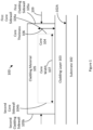
- Figure 1 illustrates a cross section of one embodiment of a planar optical waveguide configured to support a TM, e.g ., TM0, mode (or TMWG) 100.
- the TMWG 100 includes a core 104, cladding material 105, and a cladding layer 103.
- the TMWG 100 is formed on a substrate 102, e.g ., over a surface 102A of the substrate.
- the cladding layer 103 is deposited or formed on (or over) the substrate 102 which mechanically supports the TMWG 100.
- the substrate 102 for example an insulator for example undoped silicon or glass.
- the core 104 is formed on (or over) the cladding layer 103.
- the core 104 has a core thickness (or core height) 106 and a core width 107.
- the core 104 also has a first core sidewall 104a and a second core side wall 104b which are each substantially orthogonal to the substrate 102.
- the core 104 comprises silicon nitride; however, other materials can be used to form the core 104.
- the cladding material 105 is deposited or formed on (or over) the core 104, and on (or over) the cladding layer 103.
- the cladding material 105 also has a first cladding sidewall 105a and a second cladding sidewall 105b which are each substantially orthogonal to the substrate 102.
- the cladding material 105 and the cladding layer 103 may be jointly referred to as cladding.
- each of the cladding material 105 and the cladding layer 103 include silicon dioxide; however, other material(s) can be used to form each of the cladding material 105 and/or the cladding layer 103.
- the index of refraction of the cladding must be lower than the index of refraction of the core 104 to permit optical signals to be substantially confined within the TMWG 100, e.g. , within the cladding; an optical signal propagating in the TMWG 100 is configured to be substantially confined within the cladding.
- the TMWG 100 has a width 109 which is a distance between a first cladding sidewall 105a and a second cladding sidewall 105b.
- the core width 107 is less than seven free space wavelengths of the optical signal configured to be propagated in the TMWG 100.
- Embodiments of the invention may be a travelling wave resonator formed with TMWG 100 and Bragg gratings in at least one sidewall 104a, 104b of the core 104 of the TWMG 100 (collectively "TWRBG").
- TWRBG is a disc resonator formed with TMWG 100 and a Bragg grating in a sidewall 104a, 104b of the core 104 of the TMWG 100, a ring resonator formed with TMWG 100 and a Bragg grating in one or both sidewalls of the core 104 of the TMWG 100, or a racetrack resonator formed with TMWG 100 and a Bragg grating in one or both sidewalls of a core 104 of the TMWG 100.
- a racetrack resonator includes two halves of a ring resonator joined by two substantially straight portions TMWG 100.
- the Bragg gratings in sidewall(s) of the core of a TWMG 100 suppresses TE modes, including the TE0 mode, by creating optical loss for TE modes.
- the Bragg grating period is greater than a free space wavelength of an optical signal configured to propagate in the travelling wave resonator (or the planar optical waveguide thereof) divided by two times an index of refraction of the TE, e.g ., the TE0, mode. This causes electromagnetic energy of the TE mode(s) to be radiated ( i.e ., reflected in mode(s) that are lossy) by the Bragg grating in the sidewall(s) of the core.
- the Bragg grating period is also less than the free space wavelength of the optical signal configured to propagate in the travelling wave resonator (or the planar optical waveguide thereof) divided by two times an index of refraction of the TM, e.g ., the TM0, mode.
- the Bragg grating depth is selected to provide a sufficient attenuation, e.g. , greater than or equal to 60 decibels (dB), of the TE mode(s).
- the Bragg grating depth is proportional to a level of attenuation of the TE mode(s).
- Figure 2A illustrates a plan view of one embodiment of a disc resonator formed with TMWG 100 and a Bragg grating 229 in an exterior core sidewall 204A of the core 204 of the TMWG 100 (collectively DRTMWG 220A).
- the DRTMWG 220A has an exterior surface 205 which is an exterior surface of cladding.
- the core 204 is covered by cladding 291.
- the DRTMWG 220A comprises TMWG 200 formed with a cross-sectional shape of a disc over a substrate 201.
- the Bragg grating 229 includes more than one grating elements 223 in the exterior core sidewall 204A.
- Each grating element 223 may have sides that are substantially perpendicular or curved, e.g ., scalloped.
- the Bragg grating elements 223 illustrated in Figures 2A and 2B are illustrated to have sides which are substantially perpendicular.
- each grating element 223 has a grating depth (GD) 227 and a grating width (GW) 225.
- GD grating depth
- GW grating width
- each Bragg grating 229 in a sidewall (of the core of the TMWG 100) has a Bragg grating period (GP) 226.
- the Bragg grating period 226 between each Bragg grating element is substantially equal.
- the DRTMWG 220A also includes a center axis (or rotation axis) 228A around which a gyroscope (including the DRTMWG 220A) may be rotated at a rate of rotation (S2) 221.
- the core 204 has a diameter Da 224a (from the center axis 228A to the exterior core sidewall 204A).
- Figure 2B illustrates a plan view of one embodiment of a ring resonator formed with TMWG 100 and a first Bragg grating 229A in an exterior core sidewall 204A of the core 204 and/or a second Bragg grating 229B in an interior core sidewall 204B of the core 204 (collectively RTMWG 220B).
- Cladding 291 has an exterior cladding sidewall 205A and an interior cladding sidewall 205B.
- the core 204 has a diameter Db 224b (from a center axis (or rotation axis) 228B to the exterior core sidewall 205A).
- Figure 2B illustrates a first Bragg grating 229A in the exterior core sidewall 204A and a second Bragg grating 229B in the interior core sidewall 204B.
- the RTMWG 220B also includes the center axis 228B around which a gyroscope may be rotated at a rate of rotation (S2) 221.
- the RTMWG 220B has an outer diameter Db 224b (from the center axis 228B to the exterior cladding sidewall 204A).
- a racetrack resonator formed with TMWG 100 includes a first Bragg grating in a first core sidewall and/or a second Bragg grating in a second core sidewall.
- the racetrack resonator formed with TMWG 100 and including the first Bragg grating in the first core sidewall and/or the second Bragg grating in the second core sidewall also includes a center axis around which such racetrack resonator may be rotated at a rate of rotation (S2).
- S2 rate of rotation
- the mode of the optical signal is weakly or strongly confined to the cores of the resonators, e.g ., illustrated in Figures 2A and 2B .
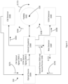
- FIG 3 illustrates a block diagram of one embodiment of a resonator optical gyroscope 330 comprising a travelling wave resonator including TMWG and a Bragg grating in at least one sidewall of the travelling wave resonator.
- the TWRBG 330C includes a center axis (or rotation axis) 328 around which the resonator optical gyroscope 330 may rotate.
- the TWRBG 330C may be implemented using the techniques described elsewhere herein, e.g ., with respect to one or more of Figures 1 , 2A, and 2B .
- the resonator optical gyroscope 330 also includes an optical source 330A, at least one optical coupler (optical coupler(s)) 330B, a clockwise optical signal detector (CW detector or CW detector circuit) 330D, a counterclockwise optical signal detector (CCW detector or CCW detector circuit) 330E, and a beat detector (or beat detector circuit) 330F.
- the beat detector may be implemented with optical, analog, and/or digital electronic circuitry.
- the optical source 330A includes one or more lasers.
- the optical source 330A is configured to generate a clockwise (CW) optical signal 330A-1 and a counterclockwise (CCW) optical signal 330A-2.
- the optical source 330A is optically coupled to the optical coupler(s) 330B.
- the optical coupler(s) 330B are also optically coupled to each of the TWRBG 330C, the CW detector 330D, the CCW detector 330E, and the beat detector 330F.
- the optical coupler(s) 330B are configured to optically couple the CW optical signal 330A-1, received from the optical source 330A, into the TWRBG 330C so that a portion 333A (of the CW optical signal 330A-1) circulates around the TWRBG 330C in a CW direction.
- each optical coupler includes, e.g. , is formed by, a planar optical waveguide, e.g ., configured to support a TM mode (for example TM0 mode), having a portion whose core is adjacent to a core of the TWRBG 330C.
- TM mode for example TM0 mode
- the optical coupler(s) 330B are also configured to optically couple, a first portion 335A of the portion 333A (of the CW optical signal 330A-1) circulating around the TWRBG 330C in the CW direction, to the CW detector 330D.
- each of the CW detector 330D and the CCW detector 330E may be a detector, e.g., a photodiode, configured to determine incident optical power level.
- Each of the CW detector 330D and the CCW detector 330E is coupled to the optical source 330A.
- the CW detector 330D provides a CW control signal 337A to the optical source 330A indicative of a power level of the first portion 335A.
- the optical coupler(s) 330B are also configured to optically couple, a first portion 335A of the portion 333A (of the CW optical signal 330A-1) circulating around the TWRBG 330C in the CW direction, to the CW detector 330D.
- the optical coupler(s) 330B are also configured to optically couple, a first portion 335B of the portion 333B (of the CCW optical signal 330A-2) circulating around the TWRBG 330C in the CCW direction, to the CCW detector 330E.
- the CCW detector 330E provides a CCW control signal 337B to the optical source 330A indicative of a power level of the first portion 335A.
- the optical source 330A is configured to use the CW control signal 337A to adjust a carrier frequency of the CW optical signal 330A-1 to be equal to the resonant frequency of TWRBG 330C in the CW direction including accounting for changes in the resonant frequency due to a rotation rate (S2) 321 around the center axis 328.
- the optical source 330A is configured to use the CCW control signal 337B to adjust a carrier frequency of the CCW optical signal 330A-2 to be equal to the resonant frequency of TWRBG 330C in the CCW direction including accounting for changes in the resonant frequency due to the rotation rate 321 around the center axis 328.
- the optical coupler(s) 330B are also configured to optically couple, to the beat detector 330F, a second portion 334A of the portion 333A (of the CW optical signal 330A-1) circulating CW around the TWRBG 330C and a second portion 334B of the portion 333B (of the CCW optical signals 333A-2) circulating CCW around the TWRBG 330C.
- the beat detector 330F is configured to determine a rate of rotation 321 around the center axis 328 of the TWRBG 330C.
- the rate of rotation 321 is a function of a difference (or beat), ⁇ f, of a carrier frequency of the second portion 334A of the portion 333A (of the CW optical signal 330A-1) circulating CW around the TWRBG 330C and a carrier frequency of the second portion 334B of the portion 333B (of the CCW optical signal 330A-2) circulating CCW around the TWRBG 330C.
- the rate of rotation 321 may also be a function of dimensions of the TWRBG 330C, e.g ., a diameter, e.g ., the core diameter D 224a, 224b, of the TWRBG, an average wavelength, ⁇ , of the CW optical signal 330A-1 and the CCW optical signal 330A-2, and a refractive index, n , of the TWRBG 330C, e.g ., of the cladding in the TWRBG 330C.
- a diameter e.g ., the core diameter D 224a, 224b
- n refractive index
- Figure 4 illustrates a flow diagram of one embodiment of a method 440 of operation of a resonator optical gyroscope comprising travelling wave resonator formed with a planar optical waveguide configured to support a TM, e.g ., TM0, mode and Bragg gratings in one or two sidewalls of the travelling wave resonator.
- TM e.g ., TM0
- method 440 may be implemented by a TWRBG and a gyroscope described elsewhere herein, e.g ., with respect to one or more of Figures 1 , 2A , 2B , and 3 .
- the blocks of the flow diagrams have been arranged in a generally sequential manner for ease of explanation; however, it is to be understood that this arrangement is merely exemplary, and it should be recognized that the processing associated with the methods (and the blocks shown in the Figures) can occur in a different order (for example, where at least some of the processing associated with the blocks is performed in parallel and/or in an event-driven manner).
- a CW optical signal is received at a TWRBG and propagated, e.g ., in a TM mode (for example a TM0 mode), clockwise around the TWRBG.
- the TWRBG may be implemented as described elsewhere herein.
- a CCW optical signal is received at a TWRBG and propagated, e.g ., in a TM mode (for example a TM0 mode), counterclockwise around the TWRBG.
- At least one portion of the CW optical signal propagating clockwise around the TWRBG is extracted from the TWRBG.
- the at least portion of the CW optical signal propagating clockwise around the TWRBG includes a first extracted portion and a second extracted portion of the CW optical signal propagating around the TWRBG.
- At least one portion of the CCW optical signal propagating counterclockwise around the TWRBG is extracted from the TWRBG.
- the at least portion of the CCW optical signal propagating clockwise around the TWRBG includes a first extracted portion and a second extracted portion of the CCW optical signal propagating around the TWRBG.
- a carrier frequency of the CW optical signal, received at the TWRBG is adjusted to equal a CW resonant frequency of the TWRBG.
- the first extracted portion of the CW optical signal propagating clockwise around the TWRBG is used to adjust the carrier frequency of the CW optical signal, received at the TWRBG, to equal the CW resonant frequency of the TWRBG.
- a carrier frequency of the CCW optical signal, received at the TWRBG is adjusted to equal a CCW resonant frequency of the TWRBG.
- the first extracted portion of the CCW optical signal propagating clockwise around the TWRBG is used to adjust the carrier frequency of the CCW optical signal, received at the TWRBG, to equal the CCW resonant frequency of the TWRBG.
- a rate of rotation of the resonant optical gyroscope around a center axis of the TWRBG is determined.
- the rate of rotation around the TWRBG may be implemented as described elsewhere herein.
- the carrier frequency of the second extracted portion of the CW optical signal and the carrier frequency of the second extracted portion of the CCW optical signal are used to determine the rate of rotation of the resonator optical gyroscope around a center axis of the TWRBG.
- Terms of relative position as used in this application are defined based on a plane parallel to, or in the case of the term coplanar - the same plane as, the conventional plane or working surface of a layer, wafer, or substrate, regardless of orientation.
- the term “horizontal” or “lateral” as used in this application are defined as a plane parallel to the conventional plane or working surface of a layer, wafer, or substrate, regardless of orientation.
- the term “vertical” refers to a direction perpendicular to the horizontal. Terms such as “on,” “side” (as in “sidewall”), “higher,” “lower,” “over,” “top,” and “under” are defined with respect to the conventional plane or working surface being on the top surface of a layer, wafer, or substrate, regardless of orientation.
- the term “coplanar” as used in this application is defined as a plane in the same plane as the conventional plane or working surface of a layer, wafer, or substrate, regardless of orientation.
- Example 1 includes a resonator configured to be mounted over a surface of a substrate, comprising: planar optical waveguide comprising: a core having a core index of refraction and a thickness which is at least ten percent of a free space wavelength of an optical signal configured to be propagated by such planar optical waveguide, wherein the thickness means a dimension along an axis perpendicular to the surface, of the substrate, under the resonator; and cladding having a cladding index of refraction and surrounding the core and over the surface of the substrate; wherein the cladding index of refraction is larger than the core index of refraction; at least one sidewall of the cladding, wherein a sidewall means a surface, of the cladding, perpendicular to the surface of the substrate; and at least one Bragg grating, wherein each Bragg grating is in a unique sidewall of the cladding; wherein a period of each Bragg grating period is greater than the free space wavelength of the optical signal
- Example 2 includes the resonator of Example 1, wherein the TM mode is a TM0 mode.
- Example 3 includes the resonator of any of Examples 1-2, wherein the TE mode is a TE0 mode.
- Example 4 includes the resonator of any of Examples 1-3, wherein the core comprises silicon nitride and the cladding comprises silicon dioxide.
- Example 5 includes the resonator of any of Examples 1-4, wherein travelling wave resonator is one of a ring resonator, a disc resonator, and a racetrack resonator.
- Example 6 includes the resonator of any of Examples 1-5, wherein the core has a width that is less than seven free space wavelengths of the optical signal configured to be propagated in the planar optical waveguide, wherein the width means a dimension along another axis substantially perpendicular to the axis of the thickness and parallel with a surface of the substrate.
- Example 7 includes the resonator of Example 6, wherein the width is a diameter of the core when the resonator is a disc resonator.
- Example 8 includes a resonator optical gyroscope, comprising: a travelling wave resonator configured to be mounted over a surface of a substrate, wherein the travelling wave resonator is configured to propagate electromagnetic energy in only one direction; the travelling wave resonator comprising: planar optical waveguide comprising: a core having a core index of refraction and a thickness which is at least ten percent of a free space wavelength of an optical signal configured to be propagated in such planar optical waveguide, wherein the thickness means a dimension along an axis perpendicular to the surface of the substrate; and cladding having a cladding index of refraction and surrounding the core and over the surface of the substrate; wherein the cladding index of refraction is larger than the core index of refraction; at least one sidewall of the cladding, wherein a sidewall means a surface, of the cladding, perpendicular to the surface of the substrate; at least one Bragg grating, wherein each Bragg grat
- Example 9 includes the resonator optical gyroscope of Example 8, wherein the TM mode is a TM0 mode.
- Example 10 includes the resonator optical gyroscope of any of Examples 8-9, wherein the TE mode is a TE0 mode.
- Example 11 includes the resonator optical gyroscope of any of Examples 8-10, wherein the core comprises silicon nitride and the cladding comprises silicon dioxide.
- Example 12 includes the resonator optical gyroscope of any of Examples 8-11, wherein travelling wave resonator is one of a ring resonator, a disc resonator, and a racetrack resonator.
- Example 13 includes the resonator optical gyroscope of any of Examples 8-12, wherein the core has a width that is less than seven free space wavelengths of the optical signal configured to be propagated in the planar optical waveguide, wherein the width means a dimension along another axis substantially perpendicular to the axis of the thickness and parallel with a surface of the substrate.
- Example 14 includes the resonator optical gyroscope of Example 13, wherein the width is a diameter of the travelling wave resonator which is a disc resonator.
- Example 16 includes a method of operation of a resonant optical gyroscope comprising travelling wave resonator configured to be mounted over a surface of a substrate, the method comprising: receiving, a clockwise (CW) optical signal at the travelling wave resonator and propagating the CW optical signal in a transverse magnetic mode clockwise around the travelling wave resonator, wherein the travelling wave resonator is configured to propagates electromagnetic energy in only one direction, and wherein the travelling wave resonator comprises: planar optical waveguide comprising: a core having a core index of refraction and a thickness which is at least ten percent of a free space wavelength of an optical signal configured to be propagated by such planar optical waveguide, wherein the thickness means a dimension along an axis perpendicular to the surface of the substrate; and cladding having a cladding index of refraction and surrounding the core and over the substrate; wherein the cladding index of refraction is larger than the core index of refraction; at least one side
- Example 17 includes the method of Example 16, wherein the TM mode is a TM0 mode.
- Example 18 includes the method of any of Examples 16-17, wherein the TE mode is a TE0 mode.
- Example 20 includes the method of any of Examples 16-19, wherein the core has a width that is less than free space wavelengths of the optical signal configured to be propagated in the travelling wave resonator, wherein the width means a dimension along another axis substantially perpendicular to the axis of the thickness and parallel with a surface of the substrate.
Landscapes
- Physics & Mathematics (AREA)
- Engineering & Computer Science (AREA)
- General Physics & Mathematics (AREA)
- Optics & Photonics (AREA)
- Microelectronics & Electronic Packaging (AREA)
- Electromagnetism (AREA)
- Power Engineering (AREA)
- Radar, Positioning & Navigation (AREA)
- Remote Sensing (AREA)
- Gyroscopes (AREA)
Abstract
Techniques are provided for implementing and using a high quality factor travelling wave resonator configured to propagate a transverse magnetic mode optical signals and suppress transverse electric mode optical signals. The travelling wave resonator may be used in a resonator optical gyroscope.
Description
- This invention was made with Government support under Contract No. 2134830-635857 awarded by the National Science Foundation. The Government has certain rights in the invention.
- Conventional planar optical waveguides support many different modes depending on the waveguide design. Among all those modes, a transverse electric (TE) mode, e.g., TE0 mode, has the highest effective index and is the fundamental mode. Corresponding loss of the conventional planar optical waveguide supporting the TE0 mode is about 0.05 dB/m.
- The loss of the conventional planar optical waveguide supporting a TE mode affects a quality, or Q, factor and finesse value of a resonator made with the conventional planar optical waveguide. A higher loss results in a lower Q factor and finesse value which is undesirable.
- A resonator configured to be mounted over a surface of a substrate is provided. The resonator comprises: planar optical waveguide comprising: a core having a core index of refraction and a thickness which is at least ten percent of a free space wavelength of an optical signal configured to be propagated by such planar optical waveguide, wherein the thickness means a dimension along an axis perpendicular to the surface, of the substrate, under the resonator; and cladding having a cladding index of refraction and surrounding the core and over the surface of the substrate; wherein the cladding index of refraction is larger than the core index of refraction; at least one sidewall of the cladding, wherein a sidewall means a surface, of the cladding, perpendicular to the surface of the substrate; and at least one Bragg grating, wherein each Bragg grating is in a unique sidewall of the cladding; wherein a period of each Bragg grating period is greater than the free space wavelength of the optical signal configured to propagate in the planar optical waveguide divided by two times an index of refraction of a transverse electric (TE) mode; wherein the period of a Bragg grating is less than the free space wavelength of the optical signal configured to propagate in the planar optical waveguide divided by two times an index of refraction of a transverse magnetic (TM) mode; wherein the resonator is a travelling wave resonator configured to propagate electromagnetic energy in only one direction.
- Understanding that the drawings depict only exemplary embodiments and are not therefore to be considered limiting in scope, the exemplary embodiments will be described with additional specificity and detail through the use of the accompanying drawings, in which:
-
Figure 1 illustrates a cross section of one embodiment a planar optical waveguide configured to support a TM mode (TMWG); -
Figure 2A illustrates a plan view of one embodiment of a disc resonator formed with TMWG and a Bragg grating in a sidewall of the disc resonator; -
Figure 2B illustrates a plan view of one embodiment of a ring resonator formed with TMWG and a first Bragg grating in a first sidewall and/or a second Bragg grating in a second sidewall; -
Figure 3 illustrates a block diagram of one embodiment of a resonator optical gyroscope comprising a travelling wave resonator including TMWG and a Bragg grating in at least one sidewall; and -
Figure 4 illustrates a flow diagram of one embodiment of a method of an operation of a resonator optical gyroscope comprising travelling wave resonator formed with a planar optical waveguide configured to support a transverse magnetic mode and with Bragg gratings in at least one sidewall of the travelling wave resonator. - In accordance with common practice, the various described features are not drawn to scale but are drawn to emphasize specific features relevant to the exemplary embodiments. Reference characters denote like elements throughout figures and text.
- In the following detailed description, reference is made to the accompanying drawings that form a part hereof, and in which is shown by way of illustration specific illustrative embodiments. However, it is to be understood that other embodiments may be utilized and that structural, mechanical, and electrical changes may be made. Furthermore, the method presented in the drawing figures and the specification is not to be construed as limiting the order in which the individual steps may be performed. The following detailed description is, therefore, not to be taken in a limiting sense.
- A travelling wave resonator made with planar optical waveguide which supports a transverse magnetic (TM), e.g., TM0, mode is provided. A travelling wave resonator means a resonator in which electromagnetic energy propagates in only one direction, e.g., clockwise or counterclockwise around the travelling wave resonator. Types of travelling wave resonators include disc, ring, and racetrack resonators. The travelling wave resonator made with planar optical waveguide which supports at least, e.g., only, one, transverse magnetic (TM), e.g., TM0, mode of an optical signal (e.g., in a resonator optical gyroscope).
- The planar optical waveguide which supports a TM mode includes a core having a thickness which is at least ten percent of the free space wavelength of the optical signal configured to be propagated by such planar optical waveguide. Corresponding loss of such planar optical waveguide supporting the TM0 mode is about 0.01 dB/m. Because the loss of such planar optical waveguide is significantly diminished, the Q factor and finesse value of a resonator made with such planar optical waveguide is significantly enhanced.
- Thickness means a dimension along an axis substantially perpendicular (or orthogonal) to a substrate upon which the travelling wave resonator (or planar optical waveguide) is formed. Width means a dimension along another axis substantially perpendicular to the axis of thickness and parallel with a surface of the substrate which supports the travelling wave resonator (or planar optical waveguide). When a resonator is formed with the planar optical waveguide, the width is a dimension of the resonator; optionally, the width is a diameter of a ring resonator or a disc resonator.
- The travelling wave resonator, including planar optical waveguide which supports a TM mode, includes a Bragg grating on at least one core sidewall of the core of the planar optical waveguide. The Bragg grating suppresses propagation of TE mode(s) in such planar optical waveguide by radiating the electromagnetic energy of the TE mode(s), but not radiating the electromagnetic energy of the TM mode(s). A core sidewall means a surface, of the core of the planar optical waveguide, which is substantially perpendicular to the substrate upon which the travelling wave resonator is formed. For example, a disc resonator only has one sidewall, where as a ring resonator and a racetrack resonator each have two sidewalls.
- The travelling wave resonator, which includes planar optical waveguide which supports a TM mode and a Bragg grating on at least one sidewall of the core of the planar optical waveguide, may be used in a resonator optical gyroscope. Because such the travelling wave resonator has a higher Q factor and a higher finesse value, the gyroscope can detect smaller changes in rotation rate of the travelling wave resonator, i.e., provide a lower angle random walk.
-
Figure 1 illustrates a cross section of one embodiment of a planar optical waveguide configured to support a TM, e.g., TM0, mode (or TMWG) 100. The TMWG 100 includes acore 104,cladding material 105, and acladding layer 103. The TMWG 100 is formed on asubstrate 102, e.g., over asurface 102A of the substrate. Thecladding layer 103 is deposited or formed on (or over) thesubstrate 102 which mechanically supports the TMWG 100. Optionally, thesubstrate 102 for example an insulator for example undoped silicon or glass. - The
core 104 is formed on (or over) thecladding layer 103. Thecore 104 has a core thickness (or core height) 106 and acore width 107. Thecore 104 also has afirst core sidewall 104a and a secondcore side wall 104b which are each substantially orthogonal to thesubstrate 102. Optionally, thecore 104 comprises silicon nitride; however, other materials can be used to form thecore 104. - The
cladding material 105 is deposited or formed on (or over) thecore 104, and on (or over) thecladding layer 103. Thecladding material 105 also has a first cladding sidewall 105a and asecond cladding sidewall 105b which are each substantially orthogonal to thesubstrate 102. - The
cladding material 105 and thecladding layer 103 may be jointly referred to as cladding. Optionally, each of thecladding material 105 and thecladding layer 103 include silicon dioxide; however, other material(s) can be used to form each of thecladding material 105 and/or thecladding layer 103. The index of refraction of the cladding must be lower than the index of refraction of thecore 104 to permit optical signals to be substantially confined within theTMWG 100, e.g., within the cladding; an optical signal propagating in theTMWG 100 is configured to be substantially confined within the cladding. - The TMWG 100 has a
width 109 which is a distance between a first cladding sidewall 105a and asecond cladding sidewall 105b. Optionally, to suppress TM modes higher than the TM0 mode, thecore width 107 is less than seven free space wavelengths of the optical signal configured to be propagated in the TMWG 100. - Embodiments of the invention may be a travelling wave resonator formed with TMWG 100 and Bragg gratings in at least one
sidewall core 104 of the TWMG 100 (collectively "TWRBG"). Examples of such TWRBG are a disc resonator formed with TMWG 100 and a Bragg grating in asidewall core 104 of the TMWG 100, a ring resonator formed with TMWG 100 and a Bragg grating in one or both sidewalls of thecore 104 of the TMWG 100, or a racetrack resonator formed with TMWG 100 and a Bragg grating in one or both sidewalls of acore 104 of the TMWG 100. A racetrack resonator includes two halves of a ring resonator joined by two substantially straight portions TMWG 100. - The Bragg gratings in sidewall(s) of the core of a
TWMG 100 suppresses TE modes, including the TE0 mode, by creating optical loss for TE modes. Firstly, the Bragg grating period is greater than a free space wavelength of an optical signal configured to propagate in the travelling wave resonator (or the planar optical waveguide thereof) divided by two times an index of refraction of the TE, e.g., the TE0, mode. This causes electromagnetic energy of the TE mode(s) to be radiated (i.e., reflected in mode(s) that are lossy) by the Bragg grating in the sidewall(s) of the core. Secondly, the Bragg grating period is also less than the free space wavelength of the optical signal configured to propagate in the travelling wave resonator (or the planar optical waveguide thereof) divided by two times an index of refraction of the TM, e.g., the TM0, mode. This prevents the electromagnetic energy of the TM mode(s) from being radiated (i.e., not reflected in mode(s) that are lossy) by the Bragg grating in the sidewall(s) of the core; thus, the Bragg grating allows the TM mode(s) to propagate in the planar optical waveguide of the travelling wave resonator. The Bragg grating depth is selected to provide a sufficient attenuation, e.g., greater than or equal to 60 decibels (dB), of the TE mode(s). The Bragg grating depth is proportional to a level of attenuation of the TE mode(s). -
Figure 2A illustrates a plan view of one embodiment of a disc resonator formed withTMWG 100 and a Bragg grating 229 in anexterior core sidewall 204A of thecore 204 of the TMWG 100 (collectively DRTMWG 220A). TheDRTMWG 220A has anexterior surface 205 which is an exterior surface of cladding. Thecore 204 is covered by cladding 291. TheDRTMWG 220A comprisesTMWG 200 formed with a cross-sectional shape of a disc over asubstrate 201. The Bragg grating 229 includes more than onegrating elements 223 in theexterior core sidewall 204A. Eachgrating element 223 may have sides that are substantially perpendicular or curved, e.g., scalloped. For pedagogical purposes, theBragg grating elements 223 illustrated inFigures 2A and 2B are illustrated to have sides which are substantially perpendicular. Optionally, eachgrating element 223 has a grating depth (GD) 227 and a grating width (GW) 225. For the embodiments described herein, each Bragg grating 229 in a sidewall (of the core of the TMWG 100) has a Bragg grating period (GP) 226. For purposes of clarity, theBragg grating period 226 between each Bragg grating element is substantially equal. TheDRTMWG 220A also includes a center axis (or rotation axis) 228A around which a gyroscope (including theDRTMWG 220A) may be rotated at a rate of rotation (S2) 221. Thecore 204 has a diameter Da 224a (from thecenter axis 228A to theexterior core sidewall 204A). -
Figure 2B illustrates a plan view of one embodiment of a ring resonator formed withTMWG 100 and a first Bragg grating 229A in anexterior core sidewall 204A of thecore 204 and/or a second Bragg grating 229B in aninterior core sidewall 204B of the core 204 (collectivelyRTMWG 220B). Cladding 291 has anexterior cladding sidewall 205A and aninterior cladding sidewall 205B. Thecore 204 has adiameter Db 224b (from a center axis (or rotation axis) 228B to theexterior core sidewall 205A). For pedagogical purposes,Figure 2B illustrates a first Bragg grating 229A in theexterior core sidewall 204A and a second Bragg grating 229B in theinterior core sidewall 204B. Each of the first and the second Bragg gratings 229A, 229B may be implemented as described elsewhere herein. TheRTMWG 220B also includes thecenter axis 228B around which a gyroscope may be rotated at a rate of rotation (S2) 221. TheRTMWG 220B has anouter diameter Db 224b (from thecenter axis 228B to theexterior cladding sidewall 204A). - A racetrack resonator formed with
TMWG 100 includes a first Bragg grating in a first core sidewall and/or a second Bragg grating in a second core sidewall. The racetrack resonator formed withTMWG 100 and including the first Bragg grating in the first core sidewall and/or the second Bragg grating in the second core sidewall also includes a center axis around which such racetrack resonator may be rotated at a rate of rotation (S2). The mode of the optical signal is weakly or strongly confined to the cores of the resonators, e.g., illustrated inFigures 2A and 2B . -
Figure 3 illustrates a block diagram of one embodiment of a resonatoroptical gyroscope 330 comprising a travelling wave resonator including TMWG and a Bragg grating in at least one sidewall of the travelling wave resonator. TheTWRBG 330C includes a center axis (or rotation axis) 328 around which the resonatoroptical gyroscope 330 may rotate. Optionally, theTWRBG 330C may be implemented using the techniques described elsewhere herein, e.g., with respect to one or more ofFigures 1 ,2A, and 2B . - The resonator
optical gyroscope 330 also includes anoptical source 330A, at least one optical coupler (optical coupler(s)) 330B, a clockwise optical signal detector (CW detector or CW detector circuit) 330D, a counterclockwise optical signal detector (CCW detector or CCW detector circuit) 330E, and a beat detector (or beat detector circuit) 330F. Optionally, the beat detector may be implemented with optical, analog, and/or digital electronic circuitry. Optionally, theoptical source 330A includes one or more lasers. Theoptical source 330A is configured to generate a clockwise (CW)optical signal 330A-1 and a counterclockwise (CCW)optical signal 330A-2. Theoptical source 330A is optically coupled to the optical coupler(s) 330B. - The optical coupler(s) 330B are also optically coupled to each of the
TWRBG 330C, theCW detector 330D, theCCW detector 330E, and thebeat detector 330F. The optical coupler(s) 330B are configured to optically couple the CWoptical signal 330A-1, received from theoptical source 330A, into theTWRBG 330C so that aportion 333A (of the CWoptical signal 330A-1) circulates around theTWRBG 330C in a CW direction. The optical coupler(s) 330B are further configured to optically couple the CCWoptical signal 330A-2, received from theoptical source 330A, into theTWRBG 330C so that aportion 333B (of the CCWoptical signal 330A-2) circulates around theTWRBG 330C in a CCW direction. Optionally, each optical coupler includes, e.g., is formed by, a planar optical waveguide, e.g., configured to support a TM mode (for example TM0 mode), having a portion whose core is adjacent to a core of theTWRBG 330C. - The optical coupler(s) 330B are also configured to optically couple, a
first portion 335A of theportion 333A (of the CWoptical signal 330A-1) circulating around theTWRBG 330C in the CW direction, to theCW detector 330D. Optionally, each of theCW detector 330D and theCCW detector 330E may be a detector, e.g., a photodiode, configured to determine incident optical power level. Each of theCW detector 330D and theCCW detector 330E is coupled to theoptical source 330A. TheCW detector 330D provides a CW control signal 337A to theoptical source 330A indicative of a power level of thefirst portion 335A. The optical coupler(s) 330B are also configured to optically couple, afirst portion 335A of theportion 333A (of the CWoptical signal 330A-1) circulating around theTWRBG 330C in the CW direction, to theCW detector 330D. The optical coupler(s) 330B are also configured to optically couple, afirst portion 335B of theportion 333B (of the CCWoptical signal 330A-2) circulating around theTWRBG 330C in the CCW direction, to theCCW detector 330E. TheCCW detector 330E provides a CCW control signal 337B to theoptical source 330A indicative of a power level of thefirst portion 335A. When the resonatoroptical gyroscope 330 is rotated around itscenter axis 328, the resonant frequencies in each of the CW and CCW directions are separated (or become different) due to the Sagnac effect. Theoptical source 330A is configured to use the CW control signal 337A to adjust a carrier frequency of the CWoptical signal 330A-1 to be equal to the resonant frequency ofTWRBG 330C in the CW direction including accounting for changes in the resonant frequency due to a rotation rate (S2) 321 around thecenter axis 328. Theoptical source 330A is configured to use the CCW control signal 337B to adjust a carrier frequency of the CCWoptical signal 330A-2 to be equal to the resonant frequency ofTWRBG 330C in the CCW direction including accounting for changes in the resonant frequency due to the rotation rate 321 around thecenter axis 328. - The optical coupler(s) 330B are also configured to optically couple, to the
beat detector 330F, asecond portion 334A of theportion 333A (of the CWoptical signal 330A-1) circulating CW around theTWRBG 330C and a second portion 334B of theportion 333B (of the CCWoptical signals 333A-2) circulating CCW around theTWRBG 330C. Thebeat detector 330F is configured to determine a rate of rotation 321 around thecenter axis 328 of theTWRBG 330C. The rate of rotation 321 is a function of a difference (or beat), Δf, of a carrier frequency of thesecond portion 334A of theportion 333A (of the CWoptical signal 330A-1) circulating CW around theTWRBG 330C and a carrier frequency of the second portion 334B of theportion 333B (of the CCWoptical signal 330A-2) circulating CCW around theTWRBG 330C. Optionally, for a ring or a disc resonator, the rate of rotation 321 may also be a function of dimensions of theTWRBG 330C, e.g., a diameter, e.g., thecore diameter D optical signal 330A-1 and the CCWoptical signal 330A-2, and a refractive index, n, of theTWRBG 330C, e.g., of the cladding in theTWRBG 330C. For each of theDRTMWG 220A and theRTMWG 220B, the rate of rotation 321 around therotation axis 328 of theTWRBG 330C is:
-
Figure 4 illustrates a flow diagram of one embodiment of amethod 440 of operation of a resonator optical gyroscope comprising travelling wave resonator formed with a planar optical waveguide configured to support a TM, e.g., TM0, mode and Bragg gratings in one or two sidewalls of the travelling wave resonator. To the extent that the methods shown in any Figures are described herein as being implemented with any of the systems illustrated herein, it is to be understood that other embodiments can be implemented in other ways. Optionally,method 440 may be implemented by a TWRBG and a gyroscope described elsewhere herein, e.g., with respect to one or more ofFigures 1 ,2A ,2B , and3 . The blocks of the flow diagrams have been arranged in a generally sequential manner for ease of explanation; however, it is to be understood that this arrangement is merely exemplary, and it should be recognized that the processing associated with the methods (and the blocks shown in the Figures) can occur in a different order (for example, where at least some of the processing associated with the blocks is performed in parallel and/or in an event-driven manner). - In
block 440A, a CW optical signal is received at a TWRBG and propagated, e.g., in a TM mode (for example a TM0 mode), clockwise around the TWRBG. Optionally, the TWRBG may be implemented as described elsewhere herein. Inblock 440B, a CCW optical signal is received at a TWRBG and propagated, e.g., in a TM mode (for example a TM0 mode), counterclockwise around the TWRBG. - In
block 440C, at least one portion of the CW optical signal propagating clockwise around the TWRBG is extracted from the TWRBG. Optionally, the at least portion of the CW optical signal propagating clockwise around the TWRBG includes a first extracted portion and a second extracted portion of the CW optical signal propagating around the TWRBG. - In
block 440D, at least one portion of the CCW optical signal propagating counterclockwise around the TWRBG is extracted from the TWRBG. Optionally, the at least portion of the CCW optical signal propagating clockwise around the TWRBG includes a first extracted portion and a second extracted portion of the CCW optical signal propagating around the TWRBG. - In
block 440E, using the at least one extracted portion of the CW optical signal, a carrier frequency of the CW optical signal, received at the TWRBG, is adjusted to equal a CW resonant frequency of the TWRBG. Optionally, the first extracted portion of the CW optical signal propagating clockwise around the TWRBG is used to adjust the carrier frequency of the CW optical signal, received at the TWRBG, to equal the CW resonant frequency of the TWRBG. - In
block 440F, using the at least one extracted portion of the CCW optical signal, a carrier frequency of the CCW optical signal, received at the TWRBG, is adjusted to equal a CCW resonant frequency of the TWRBG. Optionally, the first extracted portion of the CCW optical signal propagating clockwise around the TWRBG is used to adjust the carrier frequency of the CCW optical signal, received at the TWRBG, to equal the CCW resonant frequency of the TWRBG. - In
block 440G, using a carrier frequency of the at least one extracted portion of the CW optical signal and a carrier frequency of the at least one extracted portion of the CCW optical signal, a rate of rotation of the resonant optical gyroscope around a center axis of the TWRBG is determined. Optionally, the rate of rotation around the TWRBG may be implemented as described elsewhere herein. Optionally, the carrier frequency of the second extracted portion of the CW optical signal and the carrier frequency of the second extracted portion of the CCW optical signal are used to determine the rate of rotation of the resonator optical gyroscope around a center axis of the TWRBG.
Terms of relative position as used in this application are defined based on a plane parallel to, or in the case of the term coplanar - the same plane as, the conventional plane or working surface of a layer, wafer, or substrate, regardless of orientation. The term "horizontal" or "lateral" as used in this application are defined as a plane parallel to the conventional plane or working surface of a layer, wafer, or substrate, regardless of orientation. The term "vertical" refers to a direction perpendicular to the horizontal. Terms such as "on," "side" (as in "sidewall"), "higher," "lower," "over," "top," and "under" are defined with respect to the conventional plane or working surface being on the top surface of a layer, wafer, or substrate, regardless of orientation. The term "coplanar" as used in this application is defined as a plane in the same plane as the conventional plane or working surface of a layer, wafer, or substrate, regardless of orientation. - Example 1 includes a resonator configured to be mounted over a surface of a substrate, comprising: planar optical waveguide comprising: a core having a core index of refraction and a thickness which is at least ten percent of a free space wavelength of an optical signal configured to be propagated by such planar optical waveguide, wherein the thickness means a dimension along an axis perpendicular to the surface, of the substrate, under the resonator; and cladding having a cladding index of refraction and surrounding the core and over the surface of the substrate; wherein the cladding index of refraction is larger than the core index of refraction; at least one sidewall of the cladding, wherein a sidewall means a surface, of the cladding, perpendicular to the surface of the substrate; and at least one Bragg grating, wherein each Bragg grating is in a unique sidewall of the cladding; wherein a period of each Bragg grating period is greater than the free space wavelength of the optical signal configured to propagate in the planar optical waveguide divided by two times an index of refraction of a transverse electric (TE) mode; wherein the period of a Bragg grating is less than the free space wavelength of the optical signal configured to propagate in the planar optical waveguide divided by two times an index of refraction of a transverse magnetic (TM) mode; wherein the resonator is a travelling wave resonator configured to propagate electromagnetic energy in only one direction.
- Example 2 includes the resonator of Example 1, wherein the TM mode is a TM0 mode.
- Example 3 includes the resonator of any of Examples 1-2, wherein the TE mode is a TE0 mode.
- Example 4 includes the resonator of any of Examples 1-3, wherein the core comprises silicon nitride and the cladding comprises silicon dioxide.
- Example 5 includes the resonator of any of Examples 1-4, wherein travelling wave resonator is one of a ring resonator, a disc resonator, and a racetrack resonator.
- Example 6 includes the resonator of any of Examples 1-5, wherein the core has a width that is less than seven free space wavelengths of the optical signal configured to be propagated in the planar optical waveguide, wherein the width means a dimension along another axis substantially perpendicular to the axis of the thickness and parallel with a surface of the substrate.
- Example 7 includes the resonator of Example 6, wherein the width is a diameter of the core when the resonator is a disc resonator.
- Example 8 includes a resonator optical gyroscope, comprising: a travelling wave resonator configured to be mounted over a surface of a substrate, wherein the travelling wave resonator is configured to propagate electromagnetic energy in only one direction; the travelling wave resonator comprising: planar optical waveguide comprising: a core having a core index of refraction and a thickness which is at least ten percent of a free space wavelength of an optical signal configured to be propagated in such planar optical waveguide, wherein the thickness means a dimension along an axis perpendicular to the surface of the substrate; and cladding having a cladding index of refraction and surrounding the core and over the surface of the substrate; wherein the cladding index of refraction is larger than the core index of refraction; at least one sidewall of the cladding, wherein a sidewall means a surface, of the cladding, perpendicular to the surface of the substrate; at least one Bragg grating, wherein each Bragg grating is in a unique sidewall of the cladding; and a rotation axis around which the resonator optical gyroscope is configured to be rotated; wherein a period of each Bragg grating period is greater than the free space wavelength of the optical signal configured to propagate in the planar optical waveguide divided by two times an index of refraction of a transverse electric (TE) mode; wherein the period of a Bragg grating is less than the free space wavelength of the optical signal configured to propagate in the planar optical waveguide divided by two times an index of refraction of a transverse magnetic (TM) mode; an optical source, comprising at least one laser, configured to emit a clockwise (CW) optical signal and a counterclockwise (CCW) optical signal; at least one optical coupler configured to (a) optically couple, to the travelling wave resonator, (i) a portion of the CW optical signal configured to propagate CW around the travelling wave resonator and (ii) a portion of the CCW optical signal configured to propagate CW around the travelling wave resonator, (b) optically couple, (p) to a CW detector circuit, a first portion of the portion of the CW optical signal and (q) to a CCW detector circuit, a first portion of the portion of the CCW optical signal, and (c) optically couple, to a beat detector circuit, a second portion of the portion of the CW optical signal and a second portion of the portion of the CCW optical signal; the CW detector circuit configured to provide a CW control signal to the optical source; the CCW detector circuit configured to provide a CCW control signal to the optical source; wherein the optical source is further configured to use the CW control signal to adjust a carrier frequency of the CW optical signal to equal to a resonant frequency of the travelling wave resonator in a CW direction and use the CCW control signal to adjust a carrier frequency of the CCW optical signal to equal a resonant frequency of the travelling wave resonator in a CCW direction; and the beat detector circuit configured to determine a rate of rotation of the resonator optical gyroscope around the rotation axis based upon a difference of a carrier frequency of the second portion of the CW optical signal and a carrier frequency of the second portion of the CCW optical signal.
- Example 9 includes the resonator optical gyroscope of Example 8, wherein the TM mode is a TM0 mode.
- Example 10 includes the resonator optical gyroscope of any of Examples 8-9, wherein the TE mode is a TE0 mode.
- Example 11 includes the resonator optical gyroscope of any of Examples 8-10, wherein the core comprises silicon nitride and the cladding comprises silicon dioxide.
- Example 12 includes the resonator optical gyroscope of any of Examples 8-11, wherein travelling wave resonator is one of a ring resonator, a disc resonator, and a racetrack resonator.
- Example 13 includes the resonator optical gyroscope of any of Examples 8-12, wherein the core has a width that is less than seven free space wavelengths of the optical signal configured to be propagated in the planar optical waveguide, wherein the width means a dimension along another axis substantially perpendicular to the axis of the thickness and parallel with a surface of the substrate.
- Example 14 includes the resonator optical gyroscope of Example 13, wherein the width is a diameter of the travelling wave resonator which is a disc resonator.
- Example 15 includes the resonator optical gyroscope of any of Examples 8-14, wherein the rate of rotation is: Ω = (Δf * n * λ) / D, where D is a diameter of the travelling wave resonator, λ is an average wavelength of the CW optical signal and the CCW optical signal, and n is a refractive index of the cladding; wherein the travelling wave resonator is one of a disc resonator and a ring resonator.
- Example 16 includes a method of operation of a resonant optical gyroscope comprising travelling wave resonator configured to be mounted over a surface of a substrate, the method comprising: receiving, a clockwise (CW) optical signal at the travelling wave resonator and propagating the CW optical signal in a transverse magnetic mode clockwise around the travelling wave resonator, wherein the travelling wave resonator is configured to propagates electromagnetic energy in only one direction, and wherein the travelling wave resonator comprises: planar optical waveguide comprising: a core having a core index of refraction and a thickness which is at least ten percent of a free space wavelength of an optical signal configured to be propagated by such planar optical waveguide, wherein the thickness means a dimension along an axis perpendicular to the surface of the substrate; and cladding having a cladding index of refraction and surrounding the core and over the substrate; wherein the cladding index of refraction is larger than the core index of refraction; at least one sidewall of the cladding, wherein a sidewall means a surface, of the cladding, perpendicular to the substrate; at least one Bragg grating, wherein each Bragg grating is in a unique sidewall; and a rotation axis around which the resonant optical gyroscope is configured to be rotated; wherein a period of each Bragg grating period is greater than the free space wavelength of the optical signal configured to propagate in the travelling wave resonator divided by two times an index of refraction of a transverse electric (TE) mode; wherein the period of a Bragg grating is less than the free space wavelength of the optical signal configured to propagate in the travelling wave resonator divided by two times an index of refraction of a transverse magnetic (TM) mode; receiving, a counterclockwise (CCW) optical signal at the travelling wave resonator and propagating the CCW optical signal in the TM mode counterclockwise around the travelling wave resonator; extracting, from the travelling wave resonator, at least one portion of the CW optical signal propagating clockwise around the travelling wave resonator; extracting, from the travelling wave resonator, at least one portion of the CCW optical signal propagating counterclockwise around the travelling wave resonator; using the at least one portion of the CW optical signal, adjusting a carrier frequency of the CW optical signal, received at the travelling wave resonator, to equal a CW resonant frequency of the travelling wave resonator; using the at least one portion of the CCW optical signal, adjusting a carrier frequency of the CCW optical signal, received at the travelling wave resonator, to equal a CCW resonant frequency of the travelling wave resonator; and using a carrier frequency of the at least one portion of the CW optical signal and a carrier frequency of the at least one portion of the CCW optical signal, determining a rate of rotation around the rotation axis of the travelling wave resonator.
- Example 17 includes the method of Example 16, wherein the TM mode is a TM0 mode.
- Example 18 includes the method of any of Examples 16-17, wherein the TE mode is a TE0 mode.
- Example 19 includes the method of any of Examples 16-18, wherein the rate of rotation is: Ω = (Δf * n * λ) / D, where D is a diameter of the travelling wave resonator, λ is an average wavelength of the CW optical signal and the CCW optical signal, and n is a refractive index of the cladding; wherein the travelling wave resonator is one of a disc resonator and a ring resonator.
- Example 20 includes the method of any of Examples 16-19, wherein the core has a width that is less than free space wavelengths of the optical signal configured to be propagated in the travelling wave resonator, wherein the width means a dimension along another axis substantially perpendicular to the axis of the thickness and parallel with a surface of the substrate.
- Although specific embodiments have been illustrated and described herein, it will be appreciated by those of ordinary skill in the art that any arrangement, which is calculated to achieve the same purpose, may be substituted for the specific embodiments shown. Therefore, it is manifestly intended that this invention be limited only by the claims and the equivalents thereof.
Claims (10)
- A resonator configured to be mounted over a surface of a substrate, comprising:planar optical waveguide comprising:a core having a core index of refraction and a thickness which is at least ten percent of a free space wavelength of an optical signal configured to be propagated by such planar optical waveguide, wherein the thickness means a dimension along an axis perpendicular to the surface, of the substrate, under the resonator; andcladding having a cladding index of refraction and surrounding the core and over the surface of the substrate;wherein the cladding index of refraction is larger than the core index of refraction;at least one sidewall of the cladding, wherein a sidewall means a surface, of the cladding, perpendicular to the surface of the substrate; andat least one Bragg grating, wherein each Bragg grating is in a unique sidewall of the cladding;wherein a period of each Bragg grating period is greater than the free space wavelength of the optical signal configured to propagate in the planar optical waveguide divided by two times an index of refraction of a transverse electric (TE) mode;wherein the period of a Bragg grating is less than the free space wavelength of the optical signal configured to propagate in the planar optical waveguide divided by two times an index of refraction of a transverse magnetic (TM) mode;wherein the resonator is a travelling wave resonator configured to propagate electromagnetic energy in only one direction.
- The resonator of claim 1, wherein the TM mode is a TM0 mode, and optionally the TE mode is a TE0 mode.
- The resonator of claim 1, wherein travelling wave resonator is one of a ring resonator, a disc resonator, and a racetrack resonator.
- The resonator of claim 1, wherein the core has a width that is less than seven free space wavelengths of the optical signal configured to be propagated in the planar optical waveguide, wherein the width means a dimension along another axis substantially perpendicular to the axis of the thickness and parallel with a surface of the substrate.
- The resonator of claim 4, wherein the width is a diameter of the core when the resonator is a disc resonator.
- A resonator optical gyroscope, comprising:a travelling wave resonator configured to be mounted over a surface of a substrate, wherein the travelling wave resonator is configured to propagate electromagnetic energy in only one direction;the travelling wave resonator comprising:planar optical waveguide comprising:a core having a core index of refraction and a thickness which is at least ten percent of a free space wavelength of an optical signal configured to be propagated in such planar optical waveguide, wherein the thickness means a dimension along an axis perpendicular to the surface of the substrate; andcladding having a cladding index of refraction and surrounding the core and over the surface of the substrate;wherein the cladding index of refraction is larger than the core index of refraction;at least one sidewall of the cladding, wherein a sidewall means a surface, of the cladding, perpendicular to the surface of the substrate;at least one Bragg grating, wherein each Bragg grating is in a unique sidewall of the cladding; anda rotation axis around which the resonator optical gyroscope is configured to be rotated;wherein a period of each Bragg grating period is greater than the free space wavelength of the optical signal configured to propagate in the planar optical waveguide divided by two times an index of refraction of a transverse electric (TE) mode;wherein the period of a Bragg grating is less than the free space wavelength of the optical signal configured to propagate in the planar optical waveguide divided by two times an index of refraction of a transverse magnetic (TM) mode;an optical source, comprising at least one laser, configured to emit a clockwise (CW) optical signal and a counterclockwise (CCW) optical signal;at least one optical coupler configured to (a) optically couple, to the travelling wave resonator, (i) a portion of the CW optical signal configured to propagate CW around the travelling wave resonator and (ii) a portion of the CCW optical signal configured to propagate CW around the travelling wave resonator, (b) optically couple, (p) to a CW detector circuit, a first portion of the portion of the CW optical signal and (q) to a CCW detector circuit, a first portion of the portion of the CCW optical signal, and (c) optically couple, to a beat detector circuit, a second portion of the portion of the CW optical signal and a second portion of the portion of the CCW optical signal;the CW detector circuit configured to provide a CW control signal to the optical source;the CCW detector circuit configured to provide a CCW control signal to the optical source;wherein the optical source is further configured to use the CW control signal to adjust a carrier frequency of the CW optical signal to equal to a resonant frequency of the travelling wave resonator in a CW direction and use the CCW control signal to adjust a carrier frequency of the CCW optical signal to equal a resonant frequency of the travelling wave resonator in a CCW direction; andthe beat detector circuit configured to determine a rate of rotation of the resonator optical gyroscope around the rotation axis based upon a difference of a carrier frequency of the second portion of the CW optical signal and a carrier frequency of the second portion of the CCW optical signal.
- The resonator optical gyroscope of claim 6, wherein the TM mode is a TM0 mode, and optionally the TE mode is a TE0 mode.
- The resonator optical gyroscope of claim 6, wherein travelling wave resonator is one of a ring resonator, a disc resonator, and a racetrack resonator.
- The resonator optical gyroscope of claim 6, wherein the core has a width that is less than seven free space wavelengths of the optical signal configured to be propagated in the planar optical waveguide, wherein the width means a dimension along another axis substantially perpendicular to the axis of the thickness and parallel with a surface of the substrate.
- The resonator optical gyroscope of claim 6, wherein the rate of rotation is:

wherein the travelling wave resonator is one of a disc resonator and a ring resonator.
Applications Claiming Priority (1)
| Application Number | Priority Date | Filing Date | Title |
|---|---|---|---|
| US18/166,665 US12305988B2 (en) | 2023-02-09 | 2023-02-09 | Transverse magnetic mode travelling wave resonator with at least one Bragg grating and gyroscope applications thereof |
Publications (1)
| Publication Number | Publication Date |
|---|---|
| EP4414658A1 true EP4414658A1 (en) | 2024-08-14 |
Family
ID=88874837
Family Applications (1)
| Application Number | Title | Priority Date | Filing Date |
|---|---|---|---|
| EP23210886.0A Pending EP4414658A1 (en) | 2023-02-09 | 2023-11-20 | Transverse magnetic mode travelling wave resonator with at least one bragg grating and gyroscope applications thereof |
Country Status (2)
| Country | Link |
|---|---|
| US (1) | US12305988B2 (en) |
| EP (1) | EP4414658A1 (en) |
Families Citing this family (1)
| Publication number | Priority date | Publication date | Assignee | Title |
|---|---|---|---|---|
| US12305989B2 (en) * | 2023-02-09 | 2025-05-20 | Honeywell International Inc. | Resonator optical gyroscope with diminished bias error |
Citations (3)
| Publication number | Priority date | Publication date | Assignee | Title |
|---|---|---|---|---|
| US20040037503A1 (en) * | 2002-05-30 | 2004-02-26 | Hastings Jeffrey T. | Optical waveguide with non-uniform sidewall gratings |
| CN101952755A (en) * | 2008-02-29 | 2011-01-19 | 株式会社藤仓 | Substrate type light waveguide element, wavelength dispersion compensating element, optical filter, optical resonator and method for designing the light waveguide element, the wavelength dispersion compensating element, the filter and the resonator |
| WO2013145271A1 (en) * | 2012-03-30 | 2013-10-03 | 富士通株式会社 | Optical element, light transmitting element, light receiving element, hybrid laser, and light transmitting apparatus |
Family Cites Families (5)
| Publication number | Priority date | Publication date | Assignee | Title |
|---|---|---|---|---|
| WO2008082664A2 (en) * | 2006-12-29 | 2008-07-10 | Massachusetts Institute Of Technology | Fabrication-tolerant waveguides and resonators |
| WO2008118465A2 (en) * | 2007-03-26 | 2008-10-02 | Massachusetts Institute Of Technology | Hitless tuning and switching of optical resonator amplitude and phase responses |
| WO2015168883A1 (en) | 2014-05-07 | 2015-11-12 | 华为技术有限公司 | Transverse magnetic (tm) mode dielectric filter |
| US12050347B2 (en) * | 2022-05-24 | 2024-07-30 | Taiwan Semiconductor Manufacturing Company, Ltd. | Vertical polarizing beamsplitter for photonics |
| US12305989B2 (en) * | 2023-02-09 | 2025-05-20 | Honeywell International Inc. | Resonator optical gyroscope with diminished bias error |
-
2023
- 2023-02-09 US US18/166,665 patent/US12305988B2/en active Active
- 2023-11-20 EP EP23210886.0A patent/EP4414658A1/en active Pending
Patent Citations (3)
| Publication number | Priority date | Publication date | Assignee | Title |
|---|---|---|---|---|
| US20040037503A1 (en) * | 2002-05-30 | 2004-02-26 | Hastings Jeffrey T. | Optical waveguide with non-uniform sidewall gratings |
| CN101952755A (en) * | 2008-02-29 | 2011-01-19 | 株式会社藤仓 | Substrate type light waveguide element, wavelength dispersion compensating element, optical filter, optical resonator and method for designing the light waveguide element, the wavelength dispersion compensating element, the filter and the resonator |
| WO2013145271A1 (en) * | 2012-03-30 | 2013-10-03 | 富士通株式会社 | Optical element, light transmitting element, light receiving element, hybrid laser, and light transmitting apparatus |
Non-Patent Citations (1)
| Title |
|---|
| SCHMIDT SHON ET AL: "Improving the performance of silicon photonic rings, disks, and Bragg gratings for use in label-free biosensing", PROCEEDINGS OF SPIE, IEEE, US, vol. 9166, 27 August 2014 (2014-08-27), pages 91660M - 91660M, XP060039213, ISBN: 978-1-62841-730-2, DOI: 10.1117/12.2062389 * |
Also Published As
| Publication number | Publication date |
|---|---|
| US20240271936A1 (en) | 2024-08-15 |
| US12305988B2 (en) | 2025-05-20 |
Similar Documents
| Publication | Publication Date | Title |
|---|---|---|
| EP1706767B1 (en) | Optical coupling device | |
| US5526449A (en) | Optoelectronic integrated circuits and method of fabricating and reducing losses using same | |
| JP3349950B2 (en) | Wavelength demultiplexing circuit | |
| US4859014A (en) | Non-reciprocal optical waveguide device, particularly for use as an isolator or circulator | |
| CN103069318A (en) | Multicore fiber and core placement method for multicore fiber | |
| Akiki et al. | High-Q THz photonic crystal cavity on a low-loss suspended silicon platform | |
| CA2124710C (en) | Pumping arrangments for arrays of planar optical devices | |
| US10551563B2 (en) | Optical guide comprising a bend with a pseudo-index gradient | |
| US3659916A (en) | Single-mode dielectric waveguide | |
| US12305988B2 (en) | Transverse magnetic mode travelling wave resonator with at least one Bragg grating and gyroscope applications thereof | |
| US7321708B2 (en) | Optical fibre amplifier | |
| ITMI941137A1 (en) | OPTICAL DEVICE WITH A SPIRAL OPTICAL FIBER AND ITS PRODUCTION PROCESS | |
| EP0220315B1 (en) | Devices having low loss optical waveguides | |
| EP4414659A1 (en) | Resonator optical gyroscope with diminished bias error | |
| US10823668B2 (en) | Apparatuses and methods for alkali spectroscopy | |
| WO2021224240A1 (en) | Polarization selective resonator | |
| US11880065B2 (en) | Edge couplers integrated with dual ring resonators | |
| EP4382862A1 (en) | Travelling wave resonator with at least two cores and gyroscope applications thereof | |
| US10855372B1 (en) | Systems and methods for reduction of optical signal line width | |
| EP4286904B1 (en) | Multiple-tip edge couplers with segmented waveguide cores | |
| US12001054B2 (en) | Wideband grating coupler | |
| Nelson et al. | A ring-laser gyro based on stimulated Brillouin scattering in silicon nitride waveguides | |
| US7224868B2 (en) | Radiation-free optical cavity | |
| US20250224564A1 (en) | Polarization control in optical couplers | |
| JP2025150649A (en) | Optical resonator and optical frequency comb generator |
Legal Events
| Date | Code | Title | Description |
|---|---|---|---|
| PUAI | Public reference made under article 153(3) epc to a published international application that has entered the european phase |
Free format text: ORIGINAL CODE: 0009012 |
|
| STAA | Information on the status of an ep patent application or granted ep patent |
Free format text: STATUS: THE APPLICATION HAS BEEN PUBLISHED |
|
| AK | Designated contracting states |
Kind code of ref document: A1 Designated state(s): AL AT BE BG CH CY CZ DE DK EE ES FI FR GB GR HR HU IE IS IT LI LT LU LV MC ME MK MT NL NO PL PT RO RS SE SI SK SM TR |
|
| STAA | Information on the status of an ep patent application or granted ep patent |
Free format text: STATUS: REQUEST FOR EXAMINATION WAS MADE |
|
| 17P | Request for examination filed |
Effective date: 20250124 |