EP4414632A1 - Refrigerant distributor, heat exchanger, and air conditioner - Google Patents
Refrigerant distributor, heat exchanger, and air conditioner Download PDFInfo
- Publication number
- EP4414632A1 EP4414632A1 EP21959921.4A EP21959921A EP4414632A1 EP 4414632 A1 EP4414632 A1 EP 4414632A1 EP 21959921 A EP21959921 A EP 21959921A EP 4414632 A1 EP4414632 A1 EP 4414632A1
- Authority
- EP
- European Patent Office
- Prior art keywords
- refrigerant
- inner tube
- heat exchanger
- projection
- liquid refrigerant
- Prior art date
- Legal status (The legal status is an assumption and is not a legal conclusion. Google has not performed a legal analysis and makes no representation as to the accuracy of the status listed.)
- Withdrawn
Links
Images





Classifications
-
- F—MECHANICAL ENGINEERING; LIGHTING; HEATING; WEAPONS; BLASTING
- F25—REFRIGERATION OR COOLING; COMBINED HEATING AND REFRIGERATION SYSTEMS; HEAT PUMP SYSTEMS; MANUFACTURE OR STORAGE OF ICE; LIQUEFACTION SOLIDIFICATION OF GASES
- F25B—REFRIGERATION MACHINES, PLANTS OR SYSTEMS; COMBINED HEATING AND REFRIGERATION SYSTEMS; HEAT PUMP SYSTEMS
- F25B39/00—Evaporators; Condensers
- F25B39/02—Evaporators
- F25B39/028—Evaporators having distributing means
-
- F—MECHANICAL ENGINEERING; LIGHTING; HEATING; WEAPONS; BLASTING
- F25—REFRIGERATION OR COOLING; COMBINED HEATING AND REFRIGERATION SYSTEMS; HEAT PUMP SYSTEMS; MANUFACTURE OR STORAGE OF ICE; LIQUEFACTION SOLIDIFICATION OF GASES
- F25B—REFRIGERATION MACHINES, PLANTS OR SYSTEMS; COMBINED HEATING AND REFRIGERATION SYSTEMS; HEAT PUMP SYSTEMS
- F25B41/00—Fluid-circulation arrangements
-
- F—MECHANICAL ENGINEERING; LIGHTING; HEATING; WEAPONS; BLASTING
- F25—REFRIGERATION OR COOLING; COMBINED HEATING AND REFRIGERATION SYSTEMS; HEAT PUMP SYSTEMS; MANUFACTURE OR STORAGE OF ICE; LIQUEFACTION SOLIDIFICATION OF GASES
- F25B—REFRIGERATION MACHINES, PLANTS OR SYSTEMS; COMBINED HEATING AND REFRIGERATION SYSTEMS; HEAT PUMP SYSTEMS
- F25B41/00—Fluid-circulation arrangements
- F25B41/40—Fluid line arrangements
- F25B41/42—Arrangements for diverging or converging flows, e.g. branch lines or junctions
-
- F—MECHANICAL ENGINEERING; LIGHTING; HEATING; WEAPONS; BLASTING
- F25—REFRIGERATION OR COOLING; COMBINED HEATING AND REFRIGERATION SYSTEMS; HEAT PUMP SYSTEMS; MANUFACTURE OR STORAGE OF ICE; LIQUEFACTION SOLIDIFICATION OF GASES
- F25B—REFRIGERATION MACHINES, PLANTS OR SYSTEMS; COMBINED HEATING AND REFRIGERATION SYSTEMS; HEAT PUMP SYSTEMS
- F25B41/00—Fluid-circulation arrangements
- F25B41/40—Fluid line arrangements
- F25B41/42—Arrangements for diverging or converging flows, e.g. branch lines or junctions
- F25B41/45—Arrangements for diverging or converging flows, e.g. branch lines or junctions for flow control on the upstream side of the diverging point, e.g. with spiral structure for generating turbulence
-
- F—MECHANICAL ENGINEERING; LIGHTING; HEATING; WEAPONS; BLASTING
- F28—HEAT EXCHANGE IN GENERAL
- F28F—DETAILS OF HEAT-EXCHANGE AND HEAT-TRANSFER APPARATUS, OF GENERAL APPLICATION
- F28F9/00—Casings; Header boxes; Auxiliary supports for elements; Auxiliary members within casings
- F28F9/02—Header boxes; End plates
- F28F9/026—Header boxes; End plates with static flow control means, e.g. with means for uniformly distributing heat exchange media into conduits
- F28F9/027—Header boxes; End plates with static flow control means, e.g. with means for uniformly distributing heat exchange media into conduits in the form of distribution pipes
- F28F9/0273—Header boxes; End plates with static flow control means, e.g. with means for uniformly distributing heat exchange media into conduits in the form of distribution pipes with multiple holes
-
- F—MECHANICAL ENGINEERING; LIGHTING; HEATING; WEAPONS; BLASTING
- F28—HEAT EXCHANGE IN GENERAL
- F28D—HEAT-EXCHANGE APPARATUS, NOT PROVIDED FOR IN ANOTHER SUBCLASS, IN WHICH THE HEAT-EXCHANGE MEDIA DO NOT COME INTO DIRECT CONTACT
- F28D1/00—Heat-exchange apparatus having stationary conduit assemblies for one heat-exchange medium only, the media being in contact with different sides of the conduit wall, in which the other heat-exchange medium is a large body of fluid, e.g. domestic or motor car radiators
- F28D1/02—Heat-exchange apparatus having stationary conduit assemblies for one heat-exchange medium only, the media being in contact with different sides of the conduit wall, in which the other heat-exchange medium is a large body of fluid, e.g. domestic or motor car radiators with heat-exchange conduits immersed in the body of fluid
- F28D1/04—Heat-exchange apparatus having stationary conduit assemblies for one heat-exchange medium only, the media being in contact with different sides of the conduit wall, in which the other heat-exchange medium is a large body of fluid, e.g. domestic or motor car radiators with heat-exchange conduits immersed in the body of fluid with tubular conduits
- F28D1/053—Heat-exchange apparatus having stationary conduit assemblies for one heat-exchange medium only, the media being in contact with different sides of the conduit wall, in which the other heat-exchange medium is a large body of fluid, e.g. domestic or motor car radiators with heat-exchange conduits immersed in the body of fluid with tubular conduits the conduits being straight
- F28D1/05316—Assemblies of conduits connected to common headers, e.g. core type radiators
-
- F—MECHANICAL ENGINEERING; LIGHTING; HEATING; WEAPONS; BLASTING
- F28—HEAT EXCHANGE IN GENERAL
- F28D—HEAT-EXCHANGE APPARATUS, NOT PROVIDED FOR IN ANOTHER SUBCLASS, IN WHICH THE HEAT-EXCHANGE MEDIA DO NOT COME INTO DIRECT CONTACT
- F28D1/00—Heat-exchange apparatus having stationary conduit assemblies for one heat-exchange medium only, the media being in contact with different sides of the conduit wall, in which the other heat-exchange medium is a large body of fluid, e.g. domestic or motor car radiators
- F28D1/02—Heat-exchange apparatus having stationary conduit assemblies for one heat-exchange medium only, the media being in contact with different sides of the conduit wall, in which the other heat-exchange medium is a large body of fluid, e.g. domestic or motor car radiators with heat-exchange conduits immersed in the body of fluid
- F28D1/04—Heat-exchange apparatus having stationary conduit assemblies for one heat-exchange medium only, the media being in contact with different sides of the conduit wall, in which the other heat-exchange medium is a large body of fluid, e.g. domestic or motor car radiators with heat-exchange conduits immersed in the body of fluid with tubular conduits
- F28D1/053—Heat-exchange apparatus having stationary conduit assemblies for one heat-exchange medium only, the media being in contact with different sides of the conduit wall, in which the other heat-exchange medium is a large body of fluid, e.g. domestic or motor car radiators with heat-exchange conduits immersed in the body of fluid with tubular conduits the conduits being straight
- F28D1/0535—Heat-exchange apparatus having stationary conduit assemblies for one heat-exchange medium only, the media being in contact with different sides of the conduit wall, in which the other heat-exchange medium is a large body of fluid, e.g. domestic or motor car radiators with heat-exchange conduits immersed in the body of fluid with tubular conduits the conduits being straight the conduits having a non-circular cross-section
- F28D1/05366—Assemblies of conduits connected to common headers, e.g. core type radiators
-
- F—MECHANICAL ENGINEERING; LIGHTING; HEATING; WEAPONS; BLASTING
- F28—HEAT EXCHANGE IN GENERAL
- F28F—DETAILS OF HEAT-EXCHANGE AND HEAT-TRANSFER APPARATUS, OF GENERAL APPLICATION
- F28F1/00—Tubular elements; Assemblies of tubular elements
- F28F1/02—Tubular elements of cross-section which is non-circular
- F28F1/06—Tubular elements of cross-section which is non-circular crimped or corrugated in cross-section
-
- F—MECHANICAL ENGINEERING; LIGHTING; HEATING; WEAPONS; BLASTING
- F28—HEAT EXCHANGE IN GENERAL
- F28F—DETAILS OF HEAT-EXCHANGE AND HEAT-TRANSFER APPARATUS, OF GENERAL APPLICATION
- F28F13/00—Arrangements for modifying heat-transfer, e.g. increasing, decreasing
- F28F13/02—Arrangements for modifying heat-transfer, e.g. increasing, decreasing by influencing fluid boundary
Definitions
- the present disclosure relates to a refrigerant distributor having a double structure in which an inner pipe and an outer pipe are provided, and also to a heat exchanger and an air-conditioning apparatus that have such a refrigerant distributor.
- liquid refrigerant condensed in a heat exchanger that is provided in an indoor unit and serves as a condenser is reduced in pressure by an expansion device.
- the refrigerant then changes into two-phase gas-liquid refrigerant and flows into a heat exchanger that is provided in an outdoor unit and serves as an evaporator.
- a distribution function thereof for refrigerant is deteriorated.
- a flat tube of a heat exchanger provided in an outdoor unit is provided to face upward in a vertical direction, and a refrigerant distributor is provided to extend in a horizontal direction, thereby reducing the effect of gravity and improving the distribution of refrigerant (see, for example, Patent Literature 1).
- Patent Literature 1 Japanese Patent No. 6576577
- the distribution function greatly varies depending on the flow rate or quality (dryness fraction) of refrigerant that flows in the refrigerant distributor.
- the two-phase gas-liquid refrigerant easily separates into liquid refrigerant and gas refrigerant.
- the liquid refrigerant does not uniformly flow along an inner wall of the inner pipe, only the liquid refrigerant or only gas refrigerant flows in a given region through dispersion holes formed in the inner wall, thus deteriorating the distribution function.
- the heat exchange performance of a heat exchanger and an air-conditioning apparatus that have such a refrigerant distributor as described above is reduced.
- the present disclosure is applied in view of the above circumstances, and relates to a refrigerant distributor that uniformly distributes refrigerant to heat transfer tubes, and a heat exchanger and an air-conditioning apparatus that include such a refrigerant distributor.
- a refrigerant distributor includes: an outer tube to which a heat transfer tube is connected; and an inner tube accommodated in the outer tube and having a dispersion hole that allows refrigerant to flow to the outer tube.
- the inner tube has an inner wall on which a projection is formed to extend in an extending direction of the inner tube.
- a plurality of projections including the projection are formed on the inner wall of the inner tube and arranged in a circumferential direction of the inner tube.
- liquid refrigerant of two-phase gas-liquid refrigerant that flows in the inner tube is uniformly retained in a circumferential direction thereof between projections formed on an inner wall of the inner tube.
- the two-phase gas-liquid refrigerant uniformly flows through dispersion holes and is uniformly distributed to the heat transfer tube regardless the flow rate of the refrigerant.
- Fig. 1 is a refrigerant circuit diagram schematically illustrating a configuration of a refrigerant circuit in a refrigeration cycle apparatus 200 according to Embodiment 1. A configuration and operation of the refrigeration cycle apparatus 200 will be described with reference to Fig. 1 .
- the refrigeration cycle apparatus 200 according to Embodiment 1 includes, as elements of a refrigerant circuit, a first heat exchanger 152 provided with a first refrigerant distributor 152a, and a second heat exchanger 154 provided with a second refrigerant distributor 154a.
- the refrigeration cycle apparatus 200 includes an outdoor unit 101 and an indoor unit 102.
- the outdoor unit 101 includes a compressor 100, a flow switching device 151, the first heat exchanger 152, and an expansion device 153. Furthermore, an accumulator 300 is provided upstream of the compressor 100.
- the first refrigerant distributor 152a is provided at the first heat exchanger 152.
- the first refrigerant distributor 152a distributes refrigerant to heat transfer tubes 13 (see Fig. 2 ) of the first heat exchanger 152.
- an outdoor fan 156 is provided close to the first heat exchanger 152.
- the outdoor unit 101 further includes a controller 160.
- the indoor unit 102 includes the second heat exchanger 154.
- the second refrigerant distributor 154a is provided.
- the second refrigerant distributor 154a distributes the refrigerant to heat transfer tubes (not illustrated) of the second heat exchanger 154.
- an indoor fan 157 is provided close to the second heat exchanger 154.
- the compressor 100, the first heat exchanger 152, and the expansion device 153 are connected by pipes 155a, and the expansion device 153, the second heat exchanger 154, and the compressor 100 are connected by pipes 155b, whereby a refrigerant circuit is formed.
- the compressor 100 compresses sucked refrigerant to cause the refrigerant to be in a high-temperature and high-pressure state.
- the refrigerant compressed by the compressor 100 is discharged from the compressor 100 and is sent to the first heat exchanger 152 or the second heat exchanger 154.
- the flow switching device 151 switches the flow direction of the refrigerant between the flow direction of the refrigerant in a heating operation and that in a cooling operation. In the heating operation, the flow switching device 151 switches the flow direction of the refrigerant such that the refrigerant flows through a flow passage in which the compressor 100 is connected to the second heat exchanger 154, and in the cooling operation, the flow switching device 151 switches the flow direction of the refrigerant such that the refrigerant flows through a flow passage in which the compressor 100 is connected to the first heat exchanger 152. It should be noted that the flow switching device 151 is, for example, a four-way valve. However, a combination of two-way valves or three-way valves may be used as the flow switching device 151.
- the first heat exchanger 152 serves as an evaporator in the heating operating operation, and serves as a condenser in the cooling operation.
- heat exchange is performed between low-temperature and low-pressure refrigerant that flows out from the expansion device 153 and air sent from the outdoor fan 156, and liquid refrigerant of low-temperature and low-pressure two-phase gas-liquid refrigerant thus evaporates.
- the first heat exchanger 152 serves as a condenser
- heat exchange is performed between high-temperature and high-pressure refrigerant discharged from the compressor 100 and air sent from the outdoor fan 156, and high-temperature and high-pressure gas refrigerant thus condenses.
- the first heat exchanger 152 may be a refrigerant-to-water heat exchanger. In this case, at the first heat exchanger 152, heat exchange is performed between the refrigerant and a heat medium such as water.
- the expansion device 153 expands and decompresses refrigerant that flows out from the first heat exchanger 152 or the second heat exchanger 154.
- the expansion device 153 is, for example, an electric expansion valve that can adjust the flow rate of the refrigerant. It should be noted that as the expansion device 153, not only the electric expansion valve, but also a mechanical expansion valve that adopts a diaphragm as a pressure receiving part or a capillary tube can be applied.
- the second heat exchanger 154 serves as a condenser in the heating operation, and serves as an evaporator in the cooling operation.
- heat exchange is performed between high-temperature and high-pressure refrigerant discharged from the compressor 100 and air sent from the indoor fan 157, and high-temperature and high-pressure gas refrigerant thus condenses.
- the second heat exchanger 154 serves as an evaporator
- heat exchange is performed between low-temperature and low-pressure refrigerant that flows out from the expansion device 153 and air sent from the indoor fan 157, and low-temperature and low-pressure liquid refrigerant of two-phase gas-liquid refrigerant evaporates.
- the second heat exchanger 154 may be a refrigerant-to-water heat exchanger. In this case, at the second heat exchanger 154, heat exchange is performed between the refrigerant and a heat medium such as water.
- the first refrigerant distributor 152a distributes the refrigerant to the heat transfer tubes 13 (see Figs. 2 and 3 ) of the first heat exchanger 152.
- the outdoor fan 156 sends air for heat exchange to the first heat exchanger 152.
- the second refrigerant distributor 154a distributes the refrigerant to the heat transfer tubes (not illustrated) of the second heat exchanger 154.
- the indoor fan 157 sends air for heat exchange to the second heat exchanger 154.
- the controller 160 performs an integrated control of the entire refrigeration cycle apparatus 200. Specifically, the controller 160 controls a drive frequency of the compressor 100 depending on a required cooling capacity or heating capacity. Furthermore, the controller 160 controls the opening degree of the expansion device 153 depending on the operation state and the operation mode, that is, which of operation modes is set. In addition, the controller 160 controls the flow switching device 151 depending on which of the operation modes is set.
- the controller 160 uses information that is sent from each of temperature sensors (not illustrated) and each of pressure sensors (not illustrated) in response to an operation instruction given from a user, and controls each of actuators, for example, the compressor 100, the expansion device 153, and the flow switching device 151.
- controller 160 hardware such as a circuit device that can fulfill functions required for the controller 160 can be used.
- the controller 160 can be made up of an arithmetic device such as a microcomputer or a CPU and software that runs on the arithmetic device.
- the controller 160 is dedicated hardware or a central processing unit (CPU) that executes a program stored in a memory (the CPU being also called a processing unit, an arithmetic device, a microprocessor, a microcomputer, or a processor).
- the controller 160 corresponds to, for example, a single-component circuit, a composite circuit, an application specific integrated circuit (ASIC), a field programmable gate array (FPGA), or a combination of these circuits.
- Functions that are fulfilled by the controller 160 may be fulfilled by respective hardware or single hardware.
- the functions that are fulfilled by the controller 160 are fulfilled by software, firmware, or a combination of software and firmware.
- the software and the firmware are written as programs and stored in a memory.
- the CPU reads an associated program from the memory and executes the program.
- the memory is a nonvolatile or volatile semiconductor memory such as a RAM, a ROM, a flash memory, an EPROM, or an EEPROM. It should be noted that some of the functions of the controller 160 may be fulfilled by dedicated hardware or other some of the functions may be fulfilled by software or firmware.
- FIG. 1 illustrates the case where at the first heat exchanger 152, the first refrigerant distributor 152a is provided, and at the second heat exchanger 154, the second refrigerant distributor 154a is provided; however, at only one of the first heat exchanger 152 and the second heat exchanger 154, the associated refrigerant distributor may be provided.
- the compressor 100 is driven and discharges high-temperature and high-pressure gas refrigerant.
- the high-temperature and high-pressure gas refrigerant (single phase) discharged from the compressor 100 flows into the first heat exchanger 152.
- heat exchange is performed between the high-temperature and high-pressure gas refrigerant and air supplied by the outdoor fan 156, and the high-temperature and high-pressure gas refrigerant is condensed to change into high-pressure liquid refrigerant (single phase).
- the high-pressure liquid refrigerant sent from the first heat exchanger 152 is changed by the expansion device 153 into two-phase gas-liquid refrigerant in which low-pressure gas refrigerant and liquid refrigerant are present.
- the two-phase gas-liquid refrigerant is collected by the second refrigerant distributor 154a, and the collected two-phase gas-liquid refrigerant flows into the second heat exchanger 154.
- the two-phase gas-liquid refrigerant that has flowed thereinto after being distributed by the second refrigerant distributor 154a exchanges heat with air supplied by the indoor fan 157, and as a result, liquid refrigerant of the two-phase gas-liquid refrigerant evaporates to change into low-pressure single-phase gas refrigerant.
- the low-pressure gas refrigerant sent from the second heat exchanger 154 flows into the compressor 100 through the accumulator 300, and is compressed by the compressor 100 to change into high-temperature and high-pressure gas refrigerant.
- the high-temperature and high-pressure gas refrigerant is re-discharged from the compressor 100. This cycle is then repeatedly carried out.
- the flow of the refrigerant is switched by the flow switching device 151 to a flow indicated by solid arrows in Fig. 1 .
- the refrigerant on the discharge side of the compressor 100 may be made to flow only in a single direction without providing the flow switching device 151 on the discharge side of the compressor 100.
- the flow switching device 151 does not need to be provided.
- the refrigeration cycle apparatus 200 can be applied not only as the air-conditioning apparatus, but also as a water heater, a refrigerating machine, an air-conditioning and water-heating complex machine, etc.
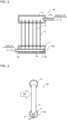
- Fig. 2 is a schematic sectional view of the first heat exchanger 152 in the refrigeration cycle apparatus 200 according to Embodiment 1 as viewed from the front.
- Fig. 3 is a schematic sectional view of the first heat exchanger 152 in the refrigeration cycle apparatus 200 according to Embodiment 1 as viewed side-on.
- Figs. 2 and 3 illustrates the first heat exchanger 152
- the second heat exchanger 154 also has the same configuration as the first heat exchanger 152.
- the second refrigerant distributor 154a of the second heat exchanger 154 has the same configuration as the first refrigerant distributor 152a of the first heat exchanger 152.
- the flow of the refrigerant in the case where the first heat exchanger 152 is used as an evaporator is indicated by an outlined arrow.
- the first heat exchanger 152 includes a plurality of heat transfer tubes 13.
- a gas header 14 and the first refrigerant distributor 152a are provided to extend in the horizontal direction.
- the heat transfer tubes 13 are arranged apart from each other in the horizontal direction; and one of ends of each of the heat transfer tubes 13 is inserted into an outer tube 11 of the first refrigerant distributor 152a, and the other end of the heat transfer tube 13 is inserted into the gas header 14.
- Fins (not illustrated) are attached to the heat transfer tubes 13 such that between any adjacent two of the heat transfer tubes 13, an associated one of the fins is located.
- the fins transfer heat to the heat transfer tubes 13.
- an outflow member 14a is provided in such a manner as to communicate with the inside of the gas header 14.
- the outflow member 14a is connected to the pipe 155a connected to the compressor 100.
- the first refrigerant distributor 152a has a double-tube structure in which an inner tube 12 and the outer tube 11 are provided. To the outer tube 11, the heat transfer tubes 13 are connected such that the heat transfer tubes 13 are arranged in an extending direction of the outer tube 11. The two-phase gas-liquid refrigerant that flows between the inner tube 12 and the outer tube 11 is distributed to the heat transfer tubes 13.
- the first refrigerant distributor 152a is connected to an inlet side of the first heat exchanger 152 that is an inlet side for two-phase gas-liquid refrigerant that flows in the case where the first heat exchanger 152 serves as an evaporator.
- the inner tube 12 is held such that the extending direction of the inner tube 12 is the horizontal direction.
- the two-phase gas-liquid refrigerant flows into one end of the inner tube 12.
- a cap 12b is provided at a most downstream part of the inner tube 12 in the flow of the refrigerant in the case where the first heat exchanger 152 serves as an evaporator.
- the pipe 155a connected to the expansion device 153 of a refrigeration cycle circuit is connected to a most upstream part of the inner tube 12 in the flow of the refrigerant in the inner tube 12 in the case where the first heat exchanger 152 serves as an evaporator.
- dispersion holes 12a that are called orifice holes and that allow the refrigerant to flow to the outer tube 11 are formed in lower portion of the inner tube 12 in the direction of gravity such that dispersion holes 12a are arranged apart from each other in the extending direction of the inner tube 12.
- the dispersion holes 12a each have a diameter of 0.5 mm to 4 mm.
- the dispersion holes 12a may be formed in the lower portion of the inner tube 12 in the direction of gravity and at positions that are located just below spaces between the heat transfer tubes 13.
- a refrigerant distributing function of the first refrigerant distributor 152a can be improved, as compared with the case where the dispersion holes 12a are formed in portions of the inner tube 12 that are located just below the heat transfer tubes 13.
- the inner tube 12 has an inflow portion 12c into which the refrigerant flows.
- Fig. 4 illustrates a cross section of the inner tube 12 of the first refrigerant distributor 152a in the refrigeration cycle apparatus 200 according to Embodiment 1.
- the cross section is a cross section perpendicular to the extending direction of the inner tube 12 of the first refrigerant distributor 152a.
- Fig. 5 is an explanatory view for the extending direction of projections 31 formed on an inner wall 12d of the inner tube 12 in the first refrigerant distributor 152a in Embodiment 1.
- the projections 31 are arranged on the inner wall 12d of the inner tube 12 in a circumferential direction thereof. As illustrated in Fig. 5 , the projections 31 are provided to extend in parallel with each other in the extending direction of the inner tube 12.
- each of the projections 31 is not limited to such a triangle as illustrated in Fig. 4 , and may be a trapezoid, a rectangle, a semi-circle, or another shape.
- liquid refrigerant 32 of the two-phase gas-liquid refrigerant is retained between the projections 31.
- the liquid refrigerant 32 is kept uniform in the circumferential direction of the inner tube 12.
- gas refrigerant 33 of the two-phase gas-liquid refrigerant flows. Therefore, the two-phase gas-liquid refrigerant uniformly flows from the inner tube 12 to the outer tube 11 through the dispersion holes 12a, and is uniformly distributed to the heat transfer tubes 13.
- the first heat exchanger 152 is operated in the heating operation, in which the first heat exchanger 152 serves as an evaporator.
- the operation of the second heat exchanger 154 in the case where the second heat exchanger 154 serves as an evaporator is the same as that of the first heat exchanger 152 in the case where the first heat exchanger 152 serves as an evaporator.
- the refrigerant flows in the opposite direction to the flow direction of the refrigerant in the case where the first heat exchanger 152 serves as an evaporator.
- the two-phase gas-liquid refrigerant that has flowed into the inflow portion 12c of the inner tube 12 flows in the inner tube 12 and are dispersed from the dispersion holes 12a of the inner tube 12 into the outer tube 11.
- the two-phase gas-liquid refrigerant dispersed into the outer tube 11 flows into the heat transfer tubes 13, and exchanges heat with air while being flowing through the heat transfer tubes 13, thereby changing into low-pressure gas refrigerant.
- the low-pressure gas refrigerant flows into the gas header 14.
- the low-pressure gas refrigerant that has flowed into the gas header 14 is output from the outflow member 14a.
- the liquid refrigerant 32 of the two-phase gas-liquid refrigerant that has flowed into the inflow portion 12c of the inner tube 12 flows between the projections 31.
- the liquid refrigerant 32 that flows between the projections 31 is kept uniform in the circumferential direction of the inner tube 12.
- the gas refrigerant 33 of the two-phase gas-liquid refrigerant flows.
- the two-phase gas-liquid refrigerant that flows in the inner tube 12 passes through the dispersion holes 12a and flows out into the outer tube 11.
- the two-phase gas-liquid refrigerant that has flowed into the outer tube 11 is distributed to the heat transfer tubes 13.
- the liquid refrigerant 32 is kept uniform in the circumferential direction between the projections 31 which extend in the extending direction of the inner tube 12. Therefore, the two-phase gas-liquid refrigerant passes through the dispersion holes 12a, uniformly flows out from the inner tube 12 into the outer tube 11 from an upstream side to a downstream side in the flow direction of the refrigerant, and is uniformly distributed to the heat transfer tubes 13.
- the two-phase gas-liquid refrigerant distributed to the heat transfer tubes 13 exchanges heat with air to change into gas refrigerant, and the gas refrigerant is output from the outflow member 14a of the gas header 14 through the gas header 14.
- the gas refrigerant output from the outflow member 14a of the gas header 14 passes through the pipe 155a, and returns to the compressor 100 through the flow switching device 151 and the accumulator 300.
- the projections 31 may be formed to extend in a direction inclined to the extending direction of the inner tube 12.
- Fig. 6 is an explanatory view for the extending direction of projections 31 of a modification that are formed on the inner wall 12d of the inner tube 12 in the first refrigerant distributor 152a according to Embodiment 1.
- Fig. 6 illustrates two of the projections 31, that is, a projection 31a and a projection 31b, as representatives of the projections 31. As illustrated in Fig. 6 , the projection 31a and the projection 31b extend in the direction inclined to the extending direction of the inner tube 12.
- liquid refrigerant is kept uniform in the circumferential direction between the projections 31a and 31b formed on the inner wall 12d of the inner tube 12.
- the two-phase gas-liquid refrigerant uniformly flows out from the dispersion holes 12a and is uniformly distributed to the heat transfer tubes 13, regardless of the flow rate of the refrigerant.
- the two-phase gas-liquid refrigerant is uniformly distributed to the heat transfer tubes 13 through the dispersion holes 12a regardless which of the heating operation and the cooling operation is performed.
- Embodiment 2 a refrigeration cycle apparatus 200 according to Embodiment 2 will be described.
- the configuration of a refrigerant circuit in Embodiment 2 is the same as that in the refrigerant circuit in the refrigeration cycle apparatus 200 according Embodiment 1, but the configuration of each of the first refrigerant distributor 152a and the second refrigerant distributor 154a is different from that in Embodiment 1.
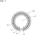
- Fig. 7 illustrates a cross section of the inner tube 12 of the first refrigerant distributor 152a in the refrigeration cycle apparatus 200 according to Embodiment 2.
- the cross section of the inner tube 12 in the first refrigerant distributor 152a is a cross section perpendicular to the extending direction of the inner tube 12.
- the projections 31 are arranged in the circumferential direction on the inner wall 12d of the inner tube 12.
- the projections 31 are provided to extend in parallel with each other in the extending direction of the inner tube 12.
- Fig. 8 is an explanatory view for the extending direction of the projections 31 formed on the inner wall 12d of the inner tube 12 in the first refrigerant distributor 152a according to Embodiment 2.
- Fig. 8 illustrates two of the projections 31, that is, a projection 31c and a projection 31d, as representatives of the projections 31.
- the projection 31c and the projection 31d are provided to helically extend in parallel with each other in the extending direction of the inner tube 12.
- the other projections 31, as well as the projections 31c and 31d are also provided to helically extend in parallel with each other in the extending direction of the inner tube 12.
- Figs. 7 and 8 illustrate the first refrigerant distributor 152a
- the second refrigerant distributor 154a also has the same configuration as the first refrigerant distributor 152a.
- the liquid refrigerant of the two-phase gas-liquid refrigerant that flows in the inner tube 12 is kept uniform between the projections 31 formed on the inner wall 12d of the inner tube 12. Furthermore, since the projections 31 are formed to extend helically, a force that keeps the refrigerant uniform in the circumferential direction of the inner tube 12 is enhanced by a centrifugal force that is generated by the liquid refrigerant when the refrigerant is flowing in the inner tube 12. Thus, the two-phase gas-liquid refrigerant uniformly flows out from the dispersion holes 12a and is uniformly distributed to the heat transfer tubes 13, regardless of the flow rate of the refrigerant.
- the projections 31 are helically formed on the inner wall 12d of the inner tube 12.
- a centrifugal force is generated by the liquid refrigerant 32 to act to keep the liquid refrigerant 32 uniform in the circumferential direction between the projections 31c and 31d.
- the two-phase gas-liquid refrigerant is uniformly dispersed from the dispersion holes 12a and is uniformly distributed to the heat transfer tubes 13 regardless of the amount of the refrigerant.
- a refrigeration cycle apparatus 200 according to Embodiment 3 will be described.
- the configuration of a refrigerant circuit according to Embodiment 3 is the same as that of the refrigerant circuit in the refrigeration cycle apparatus 200 according to Embodiment 1 which is provided as illustrated in Fig. 1 , but the configuration of each of the first refrigerant distributor 152a and the second refrigerant distributor 154a is different from that in Embodiment 1.
- Fig. 9 indicates the height of each of the projections 31 formed on the inner wall 12d of the inner tube 12 in the first refrigerant distributor 152a according to Embodiment 3.
- an outlined arrow indicates the flow of the two-phase gas-liquid refrigerant in the case where the first refrigerant distributor 152a serves as an evaporator. As illustrated in Fig.
- the height h2 of part of the projection 31 from the inner wall 12d of the inner tube 12 that is located on the downstream side in the flow of the two-phase gas-liquid refrigerant is greater than the height h1 of part of the projection 31 from the inner wall 12d of the inner tube 12 that is located on the upstream side in the flow of the two-phase gas-liquid refrigerant.
- Fig. 9 illustrates the above configuration in the first refrigerant distributor 152a
- the second refrigerant distributor 154a also has the same configuration as the first refrigerant distributor 152a.
- the two-phase gas-liquid refrigerant continuously flows to the outer tube 11 through the dispersion holes 12a.
- the flow rate of the liquid refrigerant 32 that flows in the inner tube 12 is lower on the downstream side of the two-phase gas-liquid refrigerant than on the upstream side of the two-phase gas-liquid refrigerant. Accordingly, a force by which the liquid refrigerant 32 is kept uniform on the inner wall 12d of the inner tube 12 gradually lowers in a direction from the upstream side of the two-phase gas-liquid refrigerant toward the downstream side thereof.
- the height h2 of part of the projection 31 from the inner wall 12d of the inner tube 12 that is located on the downstream side of the two-phase gas-liquid refrigerant is set greater than the height h1 of part of the projection 31 from the inner wall 12d of the inner tube 12 that is located on the upstream side of the two-phase gas-liquid refrigerant.
- each projection 31 By forming each projection 31 in the above manner, the effect of the surface tension of the liquid refrigerant 32 that flows in the inner tube 12 is increased, and the force by which the liquid refrigerant 32 is kept uniform on the inner wall 12d is increased.
- Fig. 9 illustrates the case where the height of the projection 31 gradually increases from the upstream side of the two-phase gas-liquid refrigerant toward the downstream side thereof
- the height of the projection 31 may increase in a stepwise manner from the upstream side of the two-phase gas-liquid refrigerant toward the downstream side thereof.
- the height h2 of the part of the projection 31 which is located on the downstream side is set greater than the height h1 of the part of the projection 31 which is located on the upstream side.
- the two-phase gas-liquid refrigerant uniformly flows out from the dispersion holes 12a and is uniformly distributed to the heat transfer tubes 13.
- a refrigeration cycle apparatus 200 according to Embodiment 4 will be described.
- the configuration of a refrigerant circuit according to Embodiment 4 is the same as that in the refrigerant circuit in the refrigeration cycle apparatus 200 according to Embodiment 1 which is provided as illustrated in Fig. 1 .
- the dispersion holes 12a are formed in the lower portion of the inner tube 12 in the direction of gravity, and in Embodiment 4, the positions of the dispersion holes 12a of the inner tube 12 in the first refrigerant distributor 152a are different from those in Embodiment 1.
- the positions of the dispersion holes 12a of the inner tube 12 in the second refrigerant distributor 154a are the same as those in the first refrigerant distributor 152a.
- Fig. 10 is a cross-section view that is perpendicular to the extending direction of the inner tube 12 and that indicates the positions of the dispersion holes 12a of the inner tube 12 in the first refrigerant distributor 152a according to Embodiment 4.
- the formulas (1) and (2) are obtained as the area of a sector - the area of a tringle by a trigonometric function from a liquid cross section calculated from the void fraction ⁇ .
- the dispersion holes 12a are provided at the angle ⁇ that satisfies the above formulas (1) and (2), and are thus located between a position slightly lower than a gas-liquid interface 34 in a stratified flow calculated from the void fraction and a position that is rotated from the above slightly lower position through 180°. This is because the liquid level of the gas-liquid interface 34 is located at an upper position by the surface tension than in the case where the gas-liquid interface is a gas-liquid interface in a stratified flow.
- the refrigerant distributor 152a and the second refrigerant distributor 154a in the refrigeration cycle apparatus 200 according to Embodiment 4 also, when the liquid refrigerant 32 comes from an annular flow close to the stratified flow, the two-phase gas-liquid refrigerant flows out from the gas-liquid interface 34 to the dispersion holes 12a. Thus, the refrigerant can be uniformly distributed to the heat transfer tubes 13.
- a refrigeration cycle apparatus 200 according to Embodiment 5 will be described.
- the configuration of a refrigerant circuit according to Embodiment 5 is the same as that in the refrigerant circuit in the refrigeration cycle apparatus 200 according to Embodiment 1, which is provided as illustrated in Fig. 1 .
- Embodiment 5 is different from Embodiment 1 in the positions of the projections 31 provided on the inner wall 12d of the inner tube 12 in the first refrigerant distributor 152a. It should be noted that the positions of the projections 31 in the second refrigerant distributor 154a are the same as the positions of the projections 31 in the first refrigerant distributor 152a.
- Fig. 11 is a schematic sectional view of the first heat exchanger 152 in the refrigeration cycle apparatus 200 according to Embodiment 5 as viewed from the front.
- Fig. 11 illustrates only some of the projections formed in the circumferential direction on the inner wall 12d of the inner tube 12, as a matter of convenience for illustration. It should be noted that descriptions concerning points on which the configuration as illustrated in Fig. 11 is the same as the configuration as illustrated in Fig. 2 will be omitted, and only points on which the configuration of Fig. 11 is different from that of Fig. 2 will be described.
- Fig. 11 illustrates the first heat exchanger 152
- the second heat exchanger 154 also has the same configuration as the first heat exchanger 152.
- the flow of the refrigerant is indicated by an outlined arrow in the caser where the first heat exchanger 152 serves as an evaporator.
- the inner tube 12 has a projection formation portion 41 and a smooth portion 42.
- the projection formation portion 41 is located on the upstream side in the flow of the two-phase gas-liquid refrigerant and is located upstream of the most upstream one of the dispersion holes 12a.
- the projections 31 are formed on the inner wall 12d of the inflow portion 12c of part of the inner tube 12 that is located in the projection formation portion 41.
- the smooth portion 42 is located downward of the projection formation portion 41 in the flow of the two-phase gas-liquid refrigerant.
- the inner wall 12d of part of the inner tube 12 that is lcoated in the smooth portion 42 is smooth.
- the liquid refrigerant is uniformly distributed in the circumferential direction of the inner tube 12.
- the state of the lquid refrigerant distributed in the circumferential direciton is maintained, and the liquid refrigerant also flows along the inner wall 12d in the smooth portion 42.
- the projections 31 are formed on the inner wall 12d of the inner tube 12 on the upstream side in the flow of the two-phase gas-liquid refrigerant, also in the smooth portion 42 located on the downstream side, the liquid refrigerant flows along the inner wall 12d of the inner tube 12.
- the two-phase gas-liquid refrigerant uniformly flows out from the dispersion holes 12a and is uniformly distributed to the heat transfer tubes 13.
- a refrigeration cycle apparatus 200 according to Embodiment 6 will be described.
- the cofiguraitoni of a refrigerant circuit according to Embodiment 6 is the same as that of the refrigerant cirucit in the refrigeration cycle apparatus 200 according to Embodiment 1 which is provided as illustrated in Fig. 1 .
- the positions of the projections 31 provided on the inner wall 12d of the inner tube 12 in the first refrigerant distributor 152a are different from those of the projections 31 in Embodiment 5.
- the positions of the projections 31 in the second refrigerant distributor 154a are the same as those of the projections 31 in the first refrigerant distributor 152a.
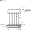
- Fig. 12 is a schematic sectional view of the first heat exchanger 152 of the refrigeration cycle apparatus 200 according to Embodiment 6 as viewed from the front.
- Fig. 12 illustrates only some of the projections 31 formed in the circumferential direction on the inner wall 12d of the inner tube 12 as a matter ofconveninece for illustration. It should be noted that descriptions concerning points on which the configuration as illustated in Fig. 12 is the same as that in Fig. 2 wil be omitted, and only points on which the configuration of Fig. 12 is different from that of Fig. 2 will be described.
- Fig. 12 also illustrates the first heat exchanger 152
- the second heat exchanger 154 has the same configuration as the first heat exchanger 152.
- the flow of the refrigerant in the case where the first heat exchanger 152 serves as an evaporator is indicated by an outlined arrow.
- the inner tube 12 has the smooth portion 42 and the projection formation portion 41.
- the inner wall 12d of the inner tube 12 is smooth, and the smooth portion 42 is located on the upstream side in the flow of the two-phase gas-liquid refrigerant.
- the projection formation portion 41 is located downstream of the smooth portion 42 in the flow of the two-phase gas-liquid refrigerant, and projections 31 are formed in the projection formation portion 41.
- the projection formation portion 41 is located downstream of a region in which the heat transfer tubes 13 are located.
- the projections 31 formed on the projection formation portion 41 are located downstream of the most dowstream one of the dispersion holes 12a, and formed on the inner wall 12d of part of the inner tube 12 that is located downstream of the region in which the heat transfer tubes 13 are located.
- the smooth portion 42 since the smooth portion 42 is located on the upstream side in the flow of the two-phase gas-liquid refrigerant, the two-phase gas-liquid refrigerant flows in a state in which a pressure loss of a region in the inner tube 12 where the flow rate of the two-phase gas-liquid refrigerant is high is reduced. Also, on the downstream side, in the projection formation portion 41, projections 31 are provided. Thus, the liquid refrigerant flows along the inner wall 12d of the inner tube 12, and even if the flow rate of the two-phase gas-liquid refrigerant is reduced, occurrence of separation between air refrigerant and liquid refrigerant is reduced.
- the liquid refrigerant flows along the inner wall 12d of the inner tube 12.
- the projections 31 are formed only in the projection formation portion 41 located on the downstream side, and the flow rate of the two-phase gas-liquid refrigerant is reduced, occurrence of separation between air refrigerant and liquid refrigerant is reduced, and the two-phase gas-liquid refrigerant uniformtly flows out from the disperson holes 12a which are located around a downstream end portion where the projections 31 are located, and are uniformtly distributed to the heat transfer tubes 13.
Landscapes
- Engineering & Computer Science (AREA)
- Physics & Mathematics (AREA)
- Mechanical Engineering (AREA)
- Thermal Sciences (AREA)
- General Engineering & Computer Science (AREA)
- Heat-Exchange Devices With Radiators And Conduit Assemblies (AREA)
- Geometry (AREA)
Abstract
Description
- The present disclosure relates to a refrigerant distributor having a double structure in which an inner pipe and an outer pipe are provided, and also to a heat exchanger and an air-conditioning apparatus that have such a refrigerant distributor.
- In the air-conditioning apparatus, liquid refrigerant condensed in a heat exchanger that is provided in an indoor unit and serves as a condenser is reduced in pressure by an expansion device. The refrigerant then changes into two-phase gas-liquid refrigerant and flows into a heat exchanger that is provided in an outdoor unit and serves as an evaporator.
- When the two-phase gas-liquid refrigerant flows into the heat exchanger serving as the evaporator, a distribution function thereof for refrigerant is deteriorated. In view of this point, in a given method, in order to improve the distribution function for refrigerant, a flat tube of a heat exchanger provided in an outdoor unit is provided to face upward in a vertical direction, and a refrigerant distributor is provided to extend in a horizontal direction, thereby reducing the effect of gravity and improving the distribution of refrigerant (see, for example, Patent Literature 1).
- Patent Literature 1:
Japanese Patent No. 6576577 - However, even in the case where the refrigerant distributor is provided to extend in the horizontal direction, the distribution function greatly varies depending on the flow rate or quality (dryness fraction) of refrigerant that flows in the refrigerant distributor. In particular, it should be noted that in the case where the flow rate and quality of the refrigerant are low, the two-phase gas-liquid refrigerant easily separates into liquid refrigerant and gas refrigerant. In the case where the liquid refrigerant does not uniformly flow along an inner wall of the inner pipe, only the liquid refrigerant or only gas refrigerant flows in a given region through dispersion holes formed in the inner wall, thus deteriorating the distribution function. In addition, the heat exchange performance of a heat exchanger and an air-conditioning apparatus that have such a refrigerant distributor as described above is reduced.
- The present disclosure is applied in view of the above circumstances, and relates to a refrigerant distributor that uniformly distributes refrigerant to heat transfer tubes, and a heat exchanger and an air-conditioning apparatus that include such a refrigerant distributor.
- A refrigerant distributor according to the present disclosure includes: an outer tube to which a heat transfer tube is connected; and an inner tube accommodated in the outer tube and having a dispersion hole that allows refrigerant to flow to the outer tube. The inner tube has an inner wall on which a projection is formed to extend in an extending direction of the inner tube. A plurality of projections including the projection are formed on the inner wall of the inner tube and arranged in a circumferential direction of the inner tube.
- According to the present disclosure, liquid refrigerant of two-phase gas-liquid refrigerant that flows in the inner tube is uniformly retained in a circumferential direction thereof between projections formed on an inner wall of the inner tube. As a result, the two-phase gas-liquid refrigerant uniformly flows through dispersion holes and is uniformly distributed to the heat transfer tube regardless the flow rate of the refrigerant.
-
- [
Fig. 1] Fig. 1 is a refrigerant circuit diagram schematically illustrating a configuration of a refrigerant circuit in a refrigeration cycle apparatus according toEmbodiment 1. - [
Fig. 2] Fig. 2 is a schematic sectional view of a first heat exchanger in the refrigeration cycle apparatus according toEmbodiment 1 as viewed from the front. - [
Fig. 3] Fig. 3 is a schematic sectional view of the first heat exchanger in the refrigeration cycle apparatus according toEmbodiment 1 as viewed side-on. - [
Fig. 4] Fig. 4 illustrates a cross section of an inner tube of a first refrigerant distributor in the refrigeration cycle apparatus according toEmbodiment 1, the cross section being perpendicular to an extending direction of the inner tube. - [
Fig. 5] Fig. 5 is an explanatory view for the extending direction of each of projections formed on an inner wall of the inner tube in the first refrigerant distributor inEmbodiment 1. - [
Fig. 6] Fig. 6 is an explanatory view for the extending direction of each of projections of a modification that are formed on the inner wall of the inner tube in the first refrigerant distributor according toEmbodiment 1. - [
Fig. 7] Fig. 7 illustrates a cross section of an inner tube in a first refrigerant distributor in a refrigeration cycle apparatus according to Embodiment 2, the cross section being perpendicular to an extending direction of the inner tube. - [
Fig. 8] Fig. 8 is an explanatory view for the extending direction of each of projections formed on an inner wall of the inner tube in the first refrigerant distributor according to Embodiment 2. - [
Fig. 9] Fig. 9 indicates the height of each of projections formed on an inner wall of an inner tube in a first refrigerant distributor according to Embodiment 3. - [
Fig. 10] Fig. 10 is a cross-section view that is perpendicular to the extending direction of an inner tube and that indicates the positions of dispersion holes of the inner tube in a first refrigerant distributor according to Embodiment 4. - [
Fig. 11] Fig. 11 is a schematic sectional view of a first heat exchanger in the refrigeration cycle apparatus according to Embodiment 5 as viewed from the front. - [
Fig. 12] Fig. 12 is a schematic sectional view of a first heat exchanger of a refrigeration cycle apparatus according to Embodiment 6 as viewed from the front. Description of Embodiments - A heat exchanger including a refrigerant distributor according to each of embodiments will be described with reference to the drawings. It should be noted that in each of figures in the drawings, components that are the same as a previous figure or previous figures are denoted by the same reference signs, and after they are each explained once, their explanations will not be repeated except an explanation or explanations that need to be repeated.
-
Fig. 1 is a refrigerant circuit diagram schematically illustrating a configuration of a refrigerant circuit in arefrigeration cycle apparatus 200 according toEmbodiment 1. A configuration and operation of therefrigeration cycle apparatus 200 will be described with reference toFig. 1 . Therefrigeration cycle apparatus 200 according to Embodiment 1 includes, as elements of a refrigerant circuit, afirst heat exchanger 152 provided with afirst refrigerant distributor 152a, and asecond heat exchanger 154 provided with a second refrigerant distributor 154a. - As illustrated in
Fig. 1 , therefrigeration cycle apparatus 200 includes anoutdoor unit 101 and anindoor unit 102. Theoutdoor unit 101 includes acompressor 100, aflow switching device 151, thefirst heat exchanger 152, and anexpansion device 153. Furthermore, anaccumulator 300 is provided upstream of thecompressor 100. At thefirst heat exchanger 152, thefirst refrigerant distributor 152a is provided. Thefirst refrigerant distributor 152a distributes refrigerant to heat transfer tubes 13 (seeFig. 2 ) of thefirst heat exchanger 152. In addition, anoutdoor fan 156 is provided close to thefirst heat exchanger 152. Theoutdoor unit 101 further includes acontroller 160. - The
indoor unit 102 includes thesecond heat exchanger 154. At thesecond heat exchanger 154, the second refrigerant distributor 154a is provided. The second refrigerant distributor 154a distributes the refrigerant to heat transfer tubes (not illustrated) of thesecond heat exchanger 154. Furthermore, anindoor fan 157 is provided close to thesecond heat exchanger 154. - The
compressor 100, thefirst heat exchanger 152, and theexpansion device 153 are connected bypipes 155a, and theexpansion device 153, thesecond heat exchanger 154, and thecompressor 100 are connected bypipes 155b, whereby a refrigerant circuit is formed. - The
compressor 100 compresses sucked refrigerant to cause the refrigerant to be in a high-temperature and high-pressure state. The refrigerant compressed by thecompressor 100 is discharged from thecompressor 100 and is sent to thefirst heat exchanger 152 or thesecond heat exchanger 154. - The
flow switching device 151 switches the flow direction of the refrigerant between the flow direction of the refrigerant in a heating operation and that in a cooling operation. In the heating operation, theflow switching device 151 switches the flow direction of the refrigerant such that the refrigerant flows through a flow passage in which thecompressor 100 is connected to thesecond heat exchanger 154, and in the cooling operation, theflow switching device 151 switches the flow direction of the refrigerant such that the refrigerant flows through a flow passage in which thecompressor 100 is connected to thefirst heat exchanger 152. It should be noted that theflow switching device 151 is, for example, a four-way valve. However, a combination of two-way valves or three-way valves may be used as theflow switching device 151. - The
first heat exchanger 152 serves as an evaporator in the heating operating operation, and serves as a condenser in the cooling operation. When thefirst heat exchanger 152 serves as an evaporator, at thefirst heat exchanger 152, heat exchange is performed between low-temperature and low-pressure refrigerant that flows out from theexpansion device 153 and air sent from theoutdoor fan 156, and liquid refrigerant of low-temperature and low-pressure two-phase gas-liquid refrigerant thus evaporates. When thefirst heat exchanger 152 serves as a condenser, at thefirst heat exchanger 152, heat exchange is performed between high-temperature and high-pressure refrigerant discharged from thecompressor 100 and air sent from theoutdoor fan 156, and high-temperature and high-pressure gas refrigerant thus condenses. It should be noted that thefirst heat exchanger 152 may be a refrigerant-to-water heat exchanger. In this case, at thefirst heat exchanger 152, heat exchange is performed between the refrigerant and a heat medium such as water. - The
expansion device 153 expands and decompresses refrigerant that flows out from thefirst heat exchanger 152 or thesecond heat exchanger 154. Theexpansion device 153 is, for example, an electric expansion valve that can adjust the flow rate of the refrigerant. It should be noted that as theexpansion device 153, not only the electric expansion valve, but also a mechanical expansion valve that adopts a diaphragm as a pressure receiving part or a capillary tube can be applied. - The
second heat exchanger 154 serves as a condenser in the heating operation, and serves as an evaporator in the cooling operation. When thesecond heat exchanger 154 serves as a condenser, at thesecond heat exchanger 154, heat exchange is performed between high-temperature and high-pressure refrigerant discharged from thecompressor 100 and air sent from theindoor fan 157, and high-temperature and high-pressure gas refrigerant thus condenses. When thesecond heat exchanger 154 serves as an evaporator, at thesecond heat exchanger 154, heat exchange is performed between low-temperature and low-pressure refrigerant that flows out from theexpansion device 153 and air sent from theindoor fan 157, and low-temperature and low-pressure liquid refrigerant of two-phase gas-liquid refrigerant evaporates. It should be noted that thesecond heat exchanger 154 may be a refrigerant-to-water heat exchanger. In this case, at thesecond heat exchanger 154, heat exchange is performed between the refrigerant and a heat medium such as water. - The
first refrigerant distributor 152a distributes the refrigerant to the heat transfer tubes 13 (seeFigs. 2 and 3 ) of thefirst heat exchanger 152. Theoutdoor fan 156 sends air for heat exchange to thefirst heat exchanger 152. The second refrigerant distributor 154a distributes the refrigerant to the heat transfer tubes (not illustrated) of thesecond heat exchanger 154. Theindoor fan 157 sends air for heat exchange to thesecond heat exchanger 154. - The
controller 160 performs an integrated control of the entirerefrigeration cycle apparatus 200. Specifically, thecontroller 160 controls a drive frequency of thecompressor 100 depending on a required cooling capacity or heating capacity. Furthermore, thecontroller 160 controls the opening degree of theexpansion device 153 depending on the operation state and the operation mode, that is, which of operation modes is set. In addition, thecontroller 160 controls theflow switching device 151 depending on which of the operation modes is set. - The
controller 160 uses information that is sent from each of temperature sensors (not illustrated) and each of pressure sensors (not illustrated) in response to an operation instruction given from a user, and controls each of actuators, for example, thecompressor 100, theexpansion device 153, and theflow switching device 151. - As the
controller 160, hardware such as a circuit device that can fulfill functions required for thecontroller 160 can be used. Alternatively, thecontroller 160 can be made up of an arithmetic device such as a microcomputer or a CPU and software that runs on the arithmetic device. - The
controller 160 is dedicated hardware or a central processing unit (CPU) that executes a program stored in a memory (the CPU being also called a processing unit, an arithmetic device, a microprocessor, a microcomputer, or a processor). In the case where thecontroller 160 is dedicated hardware, thecontroller 160 corresponds to, for example, a single-component circuit, a composite circuit, an application specific integrated circuit (ASIC), a field programmable gate array (FPGA), or a combination of these circuits. Functions that are fulfilled by thecontroller 160 may be fulfilled by respective hardware or single hardware. In the case where thecontroller 160 is a CPU, the functions that are fulfilled by thecontroller 160 are fulfilled by software, firmware, or a combination of software and firmware. The software and the firmware are written as programs and stored in a memory. To fulfill each of the functions of thecontroller 160, the CPU reads an associated program from the memory and executes the program. The memory is a nonvolatile or volatile semiconductor memory such as a RAM, a ROM, a flash memory, an EPROM, or an EEPROM. It should be noted that some of the functions of thecontroller 160 may be fulfilled by dedicated hardware or other some of the functions may be fulfilled by software or firmware. - It should be noted that
Fig. 1 illustrates the case where at thefirst heat exchanger 152, thefirst refrigerant distributor 152a is provided, and at thesecond heat exchanger 154, the second refrigerant distributor 154a is provided; however, at only one of thefirst heat exchanger 152 and thesecond heat exchanger 154, the associated refrigerant distributor may be provided. - Next, an operation of the
refrigeration cycle apparatus 200 will be described along with the flow of the refrigerant. The following description is made by referring to how therefrigeration cycle apparatus 200 is operated in the cooling operation in the case where a fluid to be subjected to heat exchange at thefirst heat exchanger 152 and thesecond heat exchanger 154 is air, for example. It should be noted that inFig. 1 , the flow of the refrigerant in the cooling operation is indicated by dashed arrows, and that of the refrigerant in the heating operation is indicated by solid arrows. - The
compressor 100 is driven and discharges high-temperature and high-pressure gas refrigerant. The high-temperature and high-pressure gas refrigerant (single phase) discharged from thecompressor 100 flows into thefirst heat exchanger 152. At thefirst heat exchanger 152, heat exchange is performed between the high-temperature and high-pressure gas refrigerant and air supplied by theoutdoor fan 156, and the high-temperature and high-pressure gas refrigerant is condensed to change into high-pressure liquid refrigerant (single phase). - The high-pressure liquid refrigerant sent from the
first heat exchanger 152 is changed by theexpansion device 153 into two-phase gas-liquid refrigerant in which low-pressure gas refrigerant and liquid refrigerant are present. The two-phase gas-liquid refrigerant is collected by the second refrigerant distributor 154a, and the collected two-phase gas-liquid refrigerant flows into thesecond heat exchanger 154. At thesecond heat exchanger 154, the two-phase gas-liquid refrigerant that has flowed thereinto after being distributed by the second refrigerant distributor 154a exchanges heat with air supplied by theindoor fan 157, and as a result, liquid refrigerant of the two-phase gas-liquid refrigerant evaporates to change into low-pressure single-phase gas refrigerant. The low-pressure gas refrigerant sent from thesecond heat exchanger 154 flows into thecompressor 100 through theaccumulator 300, and is compressed by thecompressor 100 to change into high-temperature and high-pressure gas refrigerant. The high-temperature and high-pressure gas refrigerant is re-discharged from thecompressor 100. This cycle is then repeatedly carried out. - In the heating operation, in the
refrigeration cycle apparatus 200, the flow of the refrigerant is switched by theflow switching device 151 to a flow indicated by solid arrows inFig. 1 . - The refrigerant on the discharge side of the
compressor 100 may be made to flow only in a single direction without providing theflow switching device 151 on the discharge side of thecompressor 100. - In the case where the
refrigeration cycle apparatus 200 is a dedicated refrigerant cycle apparatus for the cooling operation or the heating operation, and it is not necessary to switch the flow direction of the refrigerant, theflow switching device 151 does not need to be provided. - The
refrigeration cycle apparatus 200 can be applied not only as the air-conditioning apparatus, but also as a water heater, a refrigerating machine, an air-conditioning and water-heating complex machine, etc. -
Fig. 2 is a schematic sectional view of thefirst heat exchanger 152 in therefrigeration cycle apparatus 200 according toEmbodiment 1 as viewed from the front.Fig. 3 is a schematic sectional view of thefirst heat exchanger 152 in therefrigeration cycle apparatus 200 according toEmbodiment 1 as viewed side-on. - Although
Figs. 2 and 3 illustrates thefirst heat exchanger 152, thesecond heat exchanger 154 also has the same configuration as thefirst heat exchanger 152. Furthermore, the second refrigerant distributor 154a of thesecond heat exchanger 154 has the same configuration as thefirst refrigerant distributor 152a of thefirst heat exchanger 152. InFig. 2 , the flow of the refrigerant in the case where thefirst heat exchanger 152 is used as an evaporator is indicated by an outlined arrow. - As illustrated in
Figs. 2 and 3 , thefirst heat exchanger 152 includes a plurality ofheat transfer tubes 13. Agas header 14 and thefirst refrigerant distributor 152a are provided to extend in the horizontal direction. Theheat transfer tubes 13 are arranged apart from each other in the horizontal direction; and one of ends of each of theheat transfer tubes 13 is inserted into anouter tube 11 of thefirst refrigerant distributor 152a, and the other end of theheat transfer tube 13 is inserted into thegas header 14. Fins (not illustrated) are attached to theheat transfer tubes 13 such that between any adjacent two of theheat transfer tubes 13, an associated one of the fins is located. The fins transfer heat to theheat transfer tubes 13. In thegas header 14, anoutflow member 14a is provided in such a manner as to communicate with the inside of thegas header 14. Theoutflow member 14a is connected to thepipe 155a connected to thecompressor 100. - As illustrated in
Figs. 2 and 3 , thefirst refrigerant distributor 152a has a double-tube structure in which aninner tube 12 and theouter tube 11 are provided. To theouter tube 11, theheat transfer tubes 13 are connected such that theheat transfer tubes 13 are arranged in an extending direction of theouter tube 11. The two-phase gas-liquid refrigerant that flows between theinner tube 12 and theouter tube 11 is distributed to theheat transfer tubes 13. - The
first refrigerant distributor 152a is connected to an inlet side of thefirst heat exchanger 152 that is an inlet side for two-phase gas-liquid refrigerant that flows in the case where thefirst heat exchanger 152 serves as an evaporator. - The
inner tube 12 is held such that the extending direction of theinner tube 12 is the horizontal direction. The two-phase gas-liquid refrigerant flows into one end of theinner tube 12. Acap 12b is provided at a most downstream part of theinner tube 12 in the flow of the refrigerant in the case where thefirst heat exchanger 152 serves as an evaporator. Thepipe 155a connected to theexpansion device 153 of a refrigeration cycle circuit is connected to a most upstream part of theinner tube 12 in the flow of the refrigerant in theinner tube 12 in the case where thefirst heat exchanger 152 serves as an evaporator. - As illustrated in
Figs. 2 and 3 ,dispersion holes 12a that are called orifice holes and that allow the refrigerant to flow to theouter tube 11 are formed in lower portion of theinner tube 12 in the direction of gravity such thatdispersion holes 12a are arranged apart from each other in the extending direction of theinner tube 12. The dispersion holes 12a each have a diameter of 0.5 mm to 4 mm. The dispersion holes 12a may be formed in the lower portion of theinner tube 12 in the direction of gravity and at positions that are located just below spaces between theheat transfer tubes 13. By virtue of this configuration, a refrigerant distributing function of thefirst refrigerant distributor 152a can be improved, as compared with the case where thedispersion holes 12a are formed in portions of theinner tube 12 that are located just below theheat transfer tubes 13. In addition, theinner tube 12 has aninflow portion 12c into which the refrigerant flows. -
Fig. 4 illustrates a cross section of theinner tube 12 of thefirst refrigerant distributor 152a in therefrigeration cycle apparatus 200 according toEmbodiment 1. The cross section is a cross section perpendicular to the extending direction of theinner tube 12 of thefirst refrigerant distributor 152a.Fig. 5 is an explanatory view for the extending direction ofprojections 31 formed on aninner wall 12d of theinner tube 12 in thefirst refrigerant distributor 152a inEmbodiment 1. - As illustrated in
Fig. 4 , theprojections 31 are arranged on theinner wall 12d of theinner tube 12 in a circumferential direction thereof. As illustrated inFig. 5 , theprojections 31 are provided to extend in parallel with each other in the extending direction of theinner tube 12. - The cross section of each of the
projections 31 is not limited to such a triangle as illustrated inFig. 4 , and may be a trapezoid, a rectangle, a semi-circle, or another shape. - In such a manner, because of provision of the
projections 31,liquid refrigerant 32 of the two-phase gas-liquid refrigerant is retained between theprojections 31. As a result, theliquid refrigerant 32 is kept uniform in the circumferential direction of theinner tube 12. In a central region of theinner tube 12, gas refrigerant 33 of the two-phase gas-liquid refrigerant flows. Therefore, the two-phase gas-liquid refrigerant uniformly flows from theinner tube 12 to theouter tube 11 through thedispersion holes 12a, and is uniformly distributed to theheat transfer tubes 13. - Next, it will be described how the
first heat exchanger 152 is operated in the heating operation, in which thefirst heat exchanger 152 serves as an evaporator. It should be noted that although the following description is made with respect to the case where thefirst heat exchanger 152 serves as an evaporator, the operation of thesecond heat exchanger 154 in the case where thesecond heat exchanger 154 serves as an evaporator is the same as that of thefirst heat exchanger 152 in the case where thefirst heat exchanger 152 serves as an evaporator. Furthermore, in the case where thefirst heat exchanger 152 serves as a condenser, the refrigerant flows in the opposite direction to the flow direction of the refrigerant in the case where thefirst heat exchanger 152 serves as an evaporator. - Referring to
Fig. 2 , the two-phase gas-liquid refrigerant that has flowed into theinflow portion 12c of theinner tube 12 flows in theinner tube 12 and are dispersed from thedispersion holes 12a of theinner tube 12 into theouter tube 11. The two-phase gas-liquid refrigerant dispersed into theouter tube 11 flows into theheat transfer tubes 13, and exchanges heat with air while being flowing through theheat transfer tubes 13, thereby changing into low-pressure gas refrigerant. The low-pressure gas refrigerant flows into thegas header 14. The low-pressure gas refrigerant that has flowed into thegas header 14 is output from theoutflow member 14a. - As illustrated in
Fig. 4 , theliquid refrigerant 32 of the two-phase gas-liquid refrigerant that has flowed into theinflow portion 12c of theinner tube 12 flows between theprojections 31. The liquid refrigerant 32 that flows between theprojections 31 is kept uniform in the circumferential direction of theinner tube 12. In the central region of theinner tube 12, thegas refrigerant 33 of the two-phase gas-liquid refrigerant flows. - The two-phase gas-liquid refrigerant that flows in the
inner tube 12 passes through thedispersion holes 12a and flows out into theouter tube 11. The two-phase gas-liquid refrigerant that has flowed into theouter tube 11 is distributed to theheat transfer tubes 13. Theliquid refrigerant 32 is kept uniform in the circumferential direction between theprojections 31 which extend in the extending direction of theinner tube 12. Therefore, the two-phase gas-liquid refrigerant passes through thedispersion holes 12a, uniformly flows out from theinner tube 12 into theouter tube 11 from an upstream side to a downstream side in the flow direction of the refrigerant, and is uniformly distributed to theheat transfer tubes 13. - The two-phase gas-liquid refrigerant distributed to the
heat transfer tubes 13 exchanges heat with air to change into gas refrigerant, and the gas refrigerant is output from theoutflow member 14a of thegas header 14 through thegas header 14. The gas refrigerant output from theoutflow member 14a of thegas header 14 passes through thepipe 155a, and returns to thecompressor 100 through theflow switching device 151 and theaccumulator 300. - The
projections 31 may be formed to extend in a direction inclined to the extending direction of theinner tube 12.Fig. 6 is an explanatory view for the extending direction ofprojections 31 of a modification that are formed on theinner wall 12d of theinner tube 12 in thefirst refrigerant distributor 152a according toEmbodiment 1.Fig. 6 illustrates two of theprojections 31, that is, aprojection 31a and aprojection 31b, as representatives of theprojections 31. As illustrated inFig. 6 , theprojection 31a and theprojection 31b extend in the direction inclined to the extending direction of theinner tube 12. - In the
first refrigerant distributor 152a and the second refrigerant distributor 154a in therefrigeration cycle apparatus 200 according toEmbodiment 1, of the two-phase gas-refrigerant that flows in theinner tube 12, liquid refrigerant is kept uniform in the circumferential direction between theprojections inner wall 12d of theinner tube 12. Thus, the two-phase gas-liquid refrigerant uniformly flows out from thedispersion holes 12a and is uniformly distributed to theheat transfer tubes 13, regardless of the flow rate of the refrigerant. Furthermore, since theprojections 31 are provided in thefirst refrigerant distributor 152a and the second refrigerant distributor 154a, the two-phase gas-liquid refrigerant is uniformly distributed to theheat transfer tubes 13 through thedispersion holes 12a regardless which of the heating operation and the cooling operation is performed. - Next, a
refrigeration cycle apparatus 200 according to Embodiment 2 will be described. The configuration of a refrigerant circuit in Embodiment 2 is the same as that in the refrigerant circuit in therefrigeration cycle apparatus 200 accordingEmbodiment 1, but the configuration of each of thefirst refrigerant distributor 152a and the second refrigerant distributor 154a is different from that inEmbodiment 1. -
Fig. 7 illustrates a cross section of theinner tube 12 of thefirst refrigerant distributor 152a in therefrigeration cycle apparatus 200 according to Embodiment 2. The cross section of theinner tube 12 in thefirst refrigerant distributor 152a is a cross section perpendicular to the extending direction of theinner tube 12. - As illustrated in
Fig. 7 , theprojections 31 are arranged in the circumferential direction on theinner wall 12d of theinner tube 12. Theprojections 31 are provided to extend in parallel with each other in the extending direction of theinner tube 12. -
Fig. 8 is an explanatory view for the extending direction of theprojections 31 formed on theinner wall 12d of theinner tube 12 in thefirst refrigerant distributor 152a according to Embodiment 2.Fig. 8 illustrates two of theprojections 31, that is, aprojection 31c and aprojection 31d, as representatives of theprojections 31. Referring toFig. 8 , theprojection 31c and theprojection 31d are provided to helically extend in parallel with each other in the extending direction of theinner tube 12. Theother projections 31, as well as theprojections inner tube 12. It should be noted that althoughFigs. 7 and8 illustrate thefirst refrigerant distributor 152a, the second refrigerant distributor 154a also has the same configuration as thefirst refrigerant distributor 152a. - Because of provision of the above configuration, the liquid refrigerant of the two-phase gas-liquid refrigerant that flows in the
inner tube 12 is kept uniform between theprojections 31 formed on theinner wall 12d of theinner tube 12. Furthermore, since theprojections 31 are formed to extend helically, a force that keeps the refrigerant uniform in the circumferential direction of theinner tube 12 is enhanced by a centrifugal force that is generated by the liquid refrigerant when the refrigerant is flowing in theinner tube 12. Thus, the two-phase gas-liquid refrigerant uniformly flows out from thedispersion holes 12a and is uniformly distributed to theheat transfer tubes 13, regardless of the flow rate of the refrigerant. - In the
first refrigerant distributor 152a of therefrigeration cycle apparatus 200 according to Embodiment 2, of the two-phase gas-liquid refrigerant which flows in theinner tube 12, theprojections 31 are helically formed on theinner wall 12d of theinner tube 12. Thus, a centrifugal force is generated by the liquid refrigerant 32 to act to keep the liquid refrigerant 32 uniform in the circumferential direction between theprojections dispersion holes 12a and is uniformly distributed to theheat transfer tubes 13 regardless of the amount of the refrigerant. - A
refrigeration cycle apparatus 200 according to Embodiment 3 will be described. The configuration of a refrigerant circuit according to Embodiment 3 is the same as that of the refrigerant circuit in therefrigeration cycle apparatus 200 according toEmbodiment 1 which is provided as illustrated inFig. 1 , but the configuration of each of thefirst refrigerant distributor 152a and the second refrigerant distributor 154a is different from that inEmbodiment 1. -
Fig. 9 indicates the height of each of theprojections 31 formed on theinner wall 12d of theinner tube 12 in thefirst refrigerant distributor 152a according to Embodiment 3. InFig. 9 , an outlined arrow indicates the flow of the two-phase gas-liquid refrigerant in the case where thefirst refrigerant distributor 152a serves as an evaporator. As illustrated inFig. 9 , the height h2 of part of theprojection 31 from theinner wall 12d of theinner tube 12 that is located on the downstream side in the flow of the two-phase gas-liquid refrigerant is greater than the height h1 of part of theprojection 31 from theinner wall 12d of theinner tube 12 that is located on the upstream side in the flow of the two-phase gas-liquid refrigerant. It should be noted that althoughFig. 9 illustrates the above configuration in thefirst refrigerant distributor 152a, the second refrigerant distributor 154a also has the same configuration as thefirst refrigerant distributor 152a. - In the case where the
first heat exchanger 152 serves as an evaporator, the two-phase gas-liquid refrigerant continuously flows to theouter tube 11 through thedispersion holes 12a. As a result, the flow rate of the liquid refrigerant 32 that flows in theinner tube 12 is lower on the downstream side of the two-phase gas-liquid refrigerant than on the upstream side of the two-phase gas-liquid refrigerant. Accordingly, a force by which theliquid refrigerant 32 is kept uniform on theinner wall 12d of theinner tube 12 gradually lowers in a direction from the upstream side of the two-phase gas-liquid refrigerant toward the downstream side thereof. - In the
first refrigerant distributor 152a according to Embodiment 3, the height h2 of part of theprojection 31 from theinner wall 12d of theinner tube 12 that is located on the downstream side of the two-phase gas-liquid refrigerant is set greater than the height h1 of part of theprojection 31 from theinner wall 12d of theinner tube 12 that is located on the upstream side of the two-phase gas-liquid refrigerant. - By forming each
projection 31 in the above manner, the effect of the surface tension of the liquid refrigerant 32 that flows in theinner tube 12 is increased, and the force by which theliquid refrigerant 32 is kept uniform on theinner wall 12d is increased. - It should be noted that although
Fig. 9 illustrates the case where the height of theprojection 31 gradually increases from the upstream side of the two-phase gas-liquid refrigerant toward the downstream side thereof, the height of theprojection 31 may increase in a stepwise manner from the upstream side of the two-phase gas-liquid refrigerant toward the downstream side thereof. - In the
first refrigerant distributor 152a of therefrigeration cycle apparatus 200 according to Embodiment 3, the height h2 of the part of theprojection 31 which is located on the downstream side is set greater than the height h1 of the part of theprojection 31 which is located on the upstream side. Thus, it is possible to increase the force by which theliquid refrigerant 32 is kept uniform on theinner wall 12d. Therefore in thefirst refrigerant distributor 152a of therefrigeration cycle apparatus 200 according to Embodiment 3, the two-phase gas-liquid refrigerant uniformly flows out from thedispersion holes 12a and is uniformly distributed to theheat transfer tubes 13. - A
refrigeration cycle apparatus 200 according to Embodiment 4 will be described. The configuration of a refrigerant circuit according to Embodiment 4 is the same as that in the refrigerant circuit in therefrigeration cycle apparatus 200 according toEmbodiment 1 which is provided as illustrated inFig. 1 . InEmbodiment 1, thedispersion holes 12a are formed in the lower portion of theinner tube 12 in the direction of gravity, and in Embodiment 4, the positions of thedispersion holes 12a of theinner tube 12 in thefirst refrigerant distributor 152a are different from those inEmbodiment 1. It should be noted that the positions of thedispersion holes 12a of theinner tube 12 in the second refrigerant distributor 154a are the same as those in thefirst refrigerant distributor 152a. -
Fig. 10 is a cross-section view that is perpendicular to the extending direction of theinner tube 12 and that indicates the positions of thedispersion holes 12a of theinner tube 12 in thefirst refrigerant distributor 152a according to Embodiment 4. - An angle ϕ [deg] from a vertical line that extends from the center of the
inner tube 12 to a line that extends from the center of theinner tube 12 to each of thedispersion holes 12a satisfies the following formulas (1) and (2):

- In such a manner, the
dispersion holes 12a are provided at the angle ϕ that satisfies the above formulas (1) and (2), and are thus located between a position slightly lower than a gas-liquid interface 34 in a stratified flow calculated from the void fraction and a position that is rotated from the above slightly lower position through 180°. This is because the liquid level of the gas-liquid interface 34 is located at an upper position by the surface tension than in the case where the gas-liquid interface is a gas-liquid interface in a stratified flow. - Therefore, in the
first refrigerant distributor 152a and the second refrigerant distributor 154a in therefrigeration cycle apparatus 200 according to Embodiment 4, also, when theliquid refrigerant 32 comes from an annular flow close to the stratified flow, the two-phase gas-liquid refrigerant flows out from the gas-liquid interface 34 to thedispersion holes 12a. Thus, the refrigerant can be uniformly distributed to theheat transfer tubes 13. - A
refrigeration cycle apparatus 200 according to Embodiment 5 will be described. The configuration of a refrigerant circuit according to Embodiment 5 is the same as that in the refrigerant circuit in therefrigeration cycle apparatus 200 according toEmbodiment 1, which is provided as illustrated inFig. 1 . Embodiment 5 is different fromEmbodiment 1 in the positions of theprojections 31 provided on theinner wall 12d of theinner tube 12 in thefirst refrigerant distributor 152a. It should be noted that the positions of theprojections 31 in the second refrigerant distributor 154a are the same as the positions of theprojections 31 in thefirst refrigerant distributor 152a. -
Fig. 11 is a schematic sectional view of thefirst heat exchanger 152 in therefrigeration cycle apparatus 200 according to Embodiment 5 as viewed from the front.Fig. 11 illustrates only some of the projections formed in the circumferential direction on theinner wall 12d of theinner tube 12, as a matter of convenience for illustration. It should be noted that descriptions concerning points on which the configuration as illustrated inFig. 11 is the same as the configuration as illustrated inFig. 2 will be omitted, and only points on which the configuration ofFig. 11 is different from that ofFig. 2 will be described. - Although
Fig. 11 illustrates thefirst heat exchanger 152, thesecond heat exchanger 154 also has the same configuration as thefirst heat exchanger 152. InFig. 11 , the flow of the refrigerant is indicated by an outlined arrow in the caser where thefirst heat exchanger 152 serves as an evaporator. - As illustrated in
Fig. 11 , theinner tube 12 has aprojection formation portion 41 and asmooth portion 42. Theprojection formation portion 41 is located on the upstream side in the flow of the two-phase gas-liquid refrigerant and is located upstream of the most upstream one of thedispersion holes 12a. Theprojections 31 are formed on theinner wall 12d of theinflow portion 12c of part of theinner tube 12 that is located in theprojection formation portion 41. Thesmooth portion 42 is located downward of theprojection formation portion 41 in the flow of the two-phase gas-liquid refrigerant. Theinner wall 12d of part of theinner tube 12 that is lcoated in thesmooth portion 42 is smooth. - In the above configuration, since the
projections 31 are formed on the upstream side in the flow of the two-phase gas-liquid refrigerant, on the upstream side, the liquid refrigerant is uniformly distributed in the circumferential direction of theinner tube 12. In addition, also, when the liquid refrigerant flows from the upstream side to the downstream side, the state of the lquid refrigerant distributed in the circumferential direciton is maintained, and the liquid refrigerant also flows along theinner wall 12d in thesmooth portion 42. - Therefore, in the
first refrigerant distributor 152a according to Embodiment 5, since theprojections 31 are formed on theinner wall 12d of theinner tube 12 on the upstream side in the flow of the two-phase gas-liquid refrigerant, also in thesmooth portion 42 located on the downstream side, the liquid refrigerant flows along theinner wall 12d of theinner tube 12. Thus, even in the case where theprojections 31 are formed only on theprojection formation portion 41 located on the upstream side, in thesmooth portion 42 located on the downstream side, the two-phase gas-liquid refrigerant uniformly flows out from thedispersion holes 12a and is uniformly distributed to theheat transfer tubes 13. - A
refrigeration cycle apparatus 200 according to Embodiment 6 will be described. The cofiguraitoni of a refrigerant circuit according to Embodiment 6 is the same as that of the refrigerant cirucit in therefrigeration cycle apparatus 200 according toEmbodiment 1 which is provided as illustrated inFig. 1 . In Embodiment 6, the positions of theprojections 31 provided on theinner wall 12d of theinner tube 12 in thefirst refrigerant distributor 152a are different from those of theprojections 31 in Embodiment 5. It shoulde be noted that the positions of theprojections 31 in the second refrigerant distributor 154a are the same as those of theprojections 31 in thefirst refrigerant distributor 152a. -
Fig. 12 is a schematic sectional view of thefirst heat exchanger 152 of therefrigeration cycle apparatus 200 according to Embodiment 6 as viewed from the front.Fig. 12 illustrates only some of theprojections 31 formed in the circumferential direction on theinner wall 12d of theinner tube 12 as a matter ofconveninece for illustration. It should be noted that descriptions concerning points on which the configuration as illustated inFig. 12 is the same as that inFig. 2 wil be omitted, and only points on which the configuration ofFig. 12 is different from that ofFig. 2 will be described. - Although
Fig. 12 also illustrates thefirst heat exchanger 152, thesecond heat exchanger 154 has the same configuration as thefirst heat exchanger 152. InFig. 12 , the flow of the refrigerant in the case where thefirst heat exchanger 152 serves as an evaporator is indicated by an outlined arrow. - As illustrated in
Fig. 12 , theinner tube 12 has thesmooth portion 42 and theprojection formation portion 41. In thesmooth portion 42, theinner wall 12d of theinner tube 12 is smooth, and thesmooth portion 42 is located on the upstream side in the flow of the two-phase gas-liquid refrigerant. Theprojection formation portion 41 is located downstream of thesmooth portion 42 in the flow of the two-phase gas-liquid refrigerant, andprojections 31 are formed in theprojection formation portion 41. To be more specific, theprojection formation portion 41 is located downstream of a region in which theheat transfer tubes 13 are located. Theprojections 31 formed on theprojection formation portion 41 are located downstream of the most dowstream one of thedispersion holes 12a, and formed on theinner wall 12d of part of theinner tube 12 that is located downstream of the region in which theheat transfer tubes 13 are located. - In the above configuration, since the
smooth portion 42 is located on the upstream side in the flow of the two-phase gas-liquid refrigerant, the two-phase gas-liquid refrigerant flows in a state in which a pressure loss of a region in theinner tube 12 where the flow rate of the two-phase gas-liquid refrigerant is high is reduced. Also, on the downstream side, in theprojection formation portion 41,projections 31 are provided. Thus, the liquid refrigerant flows along theinner wall 12d of theinner tube 12, and even if the flow rate of the two-phase gas-liquid refrigerant is reduced, occurrence of separation between air refrigerant and liquid refrigerant is reduced. - Therefore, in the
first refrigerant distributor 152a according to Embodiment 6, since theprojections 31 are provided on theinner wall 12d of part of theinner tube 12 that is located on the downstream side in the flow the two-phase gas-liquid refrigerant, the liquid refrigerant flows along theinner wall 12d of theinner tube 12. Thus, even in the case where theprojections 31 are formed only in theprojection formation portion 41 located on the downstream side, and the flow rate of the two-phase gas-liquid refrigerant is reduced, occurrence of separation between air refrigerant and liquid refrigerant is reduced, and the two-phase gas-liquid refrigerant uniformtly flows out from thedisperson holes 12a which are located around a downstream end portion where theprojections 31 are located, and are uniformtly distributed to theheat transfer tubes 13. - The embodiments are described above as examples, and do not intend to define the claims. The embodiments can be put to pracitical use in various manners, and various modifications, replacement, and omissions can be made without departing from the gist of the embodiments. The embodiments and modifications thereof are covered within the range and gist of the embodiments.
- 11: outer tube, 12: inner tube, 12a: dispersion hole, 12b: cap, 12c: inflow portion, 12d: inner wall, 13: heat transfer tube, 14: gas header, 14a: outflow portion, 31, 31a-31d: projection, 32: liquid refrigerant, 33: gas refrigerant, 34: gas-liquid interface, 41: projection formation portion, 42: smooth portion, 100: compressor, 101: outdoor unit, 102: indoor unit, 151: flow switching device, 152: first heat exchanger, 152a: first refrigerant distributor, 153: expansion device, 154: second heat exchanger, 154a: second refrigerant distributor, 155a, 155b: pipe, 156: outdoor fan, 157: indoor fan, 160: controller, 200: refrigeration cycle apparatus, 300: accumulator, h1: height of projection on upstream side in flow of two-phase gas-liquid refrigerant, h2: height of projection on downstream side in flow of two-phase gas-liquid refrigerant, θ: estimated liquid level angle, α: void fraction, ϕ: angle of dispersion hole
Claims (9)
- A refrigerant distributor comprising:an outer tube to which a heat transfer tube is connected; andan inner tube accommodated in the outer tube and having a dispersion hole that allows refrigerant to flow to the outer tube,whereinthe inner tube has an inner wall on which a projection is formed to extend in an extending direction of the inner tube, anda plurality of projections including the projection are formed on the inner wall of the inner tube and arranged in a circumferential direction of the inner tube.
- The refrigerant distributor of claim 1, wherein the projection is formed to helically extend in the extending direction of the inner tube.
- The refrigerant distributor of claim 1, wherein the projection is formed to extend in a direction inclined to the extending direction of the inner tube.
- The refrigerant distributor of any one of claims 1 to 3, wherein part of the projection that is located on a downstream side in a flow of two-phase gas-liquid refrigerant has a greater height than a height of part of the projection that is located on an upstream side in the flow of the two-phase gas-liquid refrigerant.
- The refrigerant distributor of any one of claims 1 to 4, wherein an angle ϕ from a vertical line that extends from a center of the inner tube to a line that extends to the dispersion hole is set to satisfy the following formulas (1) and (2):


- The refrigerant distributor of any one of claims 1 to 5, wherein the inner tube is provided on an upstream side in a flow of two-phase gas-liquid refrigerant, and has a projection formation portion in which the projection is formed and a smooth portion which is located downstream of the projection formation portion in the flow of the two-phase gas-liquid refrigerant and in which the inner wall of the inner tube is smooth.
- The refrigerant distributor of any one of claims 1 to 5, wherein the inner tube is provided on an upstream side in a flow of two-phase gas-liquid refrigerant, and has a smooth portion in which the inner wall of the inner tube is smooth and a projection formation portion which is located downward of the smooth portion in the flow of the two-phase gas-liquid refrigerant and in which the projection is provided.
- A heat exchanger comprising the refrigerant distributor of any one of claims 1 to 7.
- An air-conditioning apparatus comprising the heat exchanger of claim 8.
Applications Claiming Priority (1)
| Application Number | Priority Date | Filing Date | Title |
|---|---|---|---|
| PCT/JP2021/037091 WO2023058179A1 (en) | 2021-10-07 | 2021-10-07 | Refrigerant distributor, heat exchanger, and air conditioner |
Publications (1)
| Publication Number | Publication Date |
|---|---|
| EP4414632A1 true EP4414632A1 (en) | 2024-08-14 |
Family
ID=85803291
Family Applications (1)
| Application Number | Title | Priority Date | Filing Date |
|---|---|---|---|
| EP21959921.4A Withdrawn EP4414632A1 (en) | 2021-10-07 | 2021-10-07 | Refrigerant distributor, heat exchanger, and air conditioner |
Country Status (5)
| Country | Link |
|---|---|
| US (1) | US20240310093A1 (en) |
| EP (1) | EP4414632A1 (en) |
| JP (1) | JPWO2023058179A1 (en) |
| CN (1) | CN118043609A (en) |
| WO (1) | WO2023058179A1 (en) |
Families Citing this family (1)
| Publication number | Priority date | Publication date | Assignee | Title |
|---|---|---|---|---|
| CN116817628A (en) * | 2022-04-22 | 2023-09-29 | 浙江三花智能控制股份有限公司 | Heat Exchanger |
Family Cites Families (9)
| Publication number | Priority date | Publication date | Assignee | Title |
|---|---|---|---|---|
| US7806171B2 (en) * | 2004-11-12 | 2010-10-05 | Carrier Corporation | Parallel flow evaporator with spiral inlet manifold |
| US7275394B2 (en) * | 2005-04-22 | 2007-10-02 | Visteon Global Technologies, Inc. | Heat exchanger having a distributer plate |
| JP2010139196A (en) * | 2008-12-15 | 2010-06-24 | Sharp Corp | Heat exchanger |
| JP2011017505A (en) * | 2009-07-10 | 2011-01-27 | Mitsubishi Electric Corp | Refrigerant distributor and heat pump device |
| CN101839590B (en) * | 2010-02-22 | 2012-03-21 | 三花丹佛斯(杭州)微通道换热器有限公司 | Micro-passage heat exchanger |
| US20110290465A1 (en) * | 2010-06-01 | 2011-12-01 | Delphi Technologies, Inc. | Orientation insensitive refrigerant distributor tube |
| JP2012002475A (en) * | 2010-06-21 | 2012-01-05 | Mitsubishi Electric Corp | Refrigerant distributor, and heat pump device using the refrigerant distributor |
| FR3059410B1 (en) * | 2016-11-30 | 2019-07-19 | Valeo Systemes Thermiques | MIXING DEVICE COMPRISING A DEVICE FOR HOMOGENIZING THE DISTRIBUTION OF A REFRIGERANT FLUID WITHIN HEAT EXCHANGER TUBES |
| EP3805687B1 (en) | 2018-06-11 | 2024-01-17 | Mitsubishi Electric Corporation | Refrigerant distributor, heat exchanger, and air conditioner |
-
2021
- 2021-10-07 US US18/681,233 patent/US20240310093A1/en active Pending
- 2021-10-07 CN CN202180102909.6A patent/CN118043609A/en not_active Withdrawn
- 2021-10-07 JP JP2023552621A patent/JPWO2023058179A1/ja not_active Withdrawn
- 2021-10-07 WO PCT/JP2021/037091 patent/WO2023058179A1/en not_active Ceased
- 2021-10-07 EP EP21959921.4A patent/EP4414632A1/en not_active Withdrawn
Also Published As
| Publication number | Publication date |
|---|---|
| US20240310093A1 (en) | 2024-09-19 |
| WO2023058179A1 (en) | 2023-04-13 |
| CN118043609A (en) | 2024-05-14 |
| JPWO2023058179A1 (en) | 2023-04-13 |
Similar Documents
| Publication | Publication Date | Title |
|---|---|---|
| JP6595125B1 (en) | Air conditioner outdoor unit and air conditioner | |
| EP2851641B1 (en) | Heat exchanger, indoor unit, and refrigeration cycle device | |
| CN101086352B (en) | Air conditioner | |
| JP6576577B1 (en) | Refrigerant distributor, heat exchanger, and air conditioner | |
| EP3205968A1 (en) | Heat exchanger and air conditioning device | |
| EP2995886A1 (en) | Heat exchanger and refrigeration cycle device | |
| JP6925393B2 (en) | Outdoor unit of air conditioner and air conditioner | |
| CN103574952A (en) | Refrigeration cycle apparatus and refrigeration unit and air-conditioning system equipped with the refrigeration cycle apparatus | |
| EP4414632A1 (en) | Refrigerant distributor, heat exchanger, and air conditioner | |
| EP3985315B1 (en) | Air conditioner | |
| EP4350273A1 (en) | Heat exchanger and air conditioner | |
| US11859883B2 (en) | Flow disturbance apparatus and air conditioner comprising the same | |
| KR20050077139A (en) | Multi airconditioner | |
| EP3825628B1 (en) | Refrigeration cycle device | |
| JP5704898B2 (en) | Heat exchanger and air conditioner equipped with the heat exchanger | |
| US20220136740A1 (en) | Refrigeration cycle apparatus | |
| EP3594591B1 (en) | Heat exchanger and air conditioner | |
| EP4083558B1 (en) | Heat exchanger and refrigeration cycle device | |
| CN117355721A (en) | Heat exchanger, outdoor unit of air-conditioning device provided with heat exchanger, and air-conditioning device provided with outdoor unit of air-conditioning device | |
| JP7738754B2 (en) | Heat exchanger and refrigeration cycle device | |
| US20240280328A1 (en) | Plate heat exchanger | |
| JP7612110B1 (en) | Heat exchanger, outdoor unit and air conditioning device | |
| JP7210609B2 (en) | air conditioner | |
| EP4006474A1 (en) | Heat exchanger and refrigeration cycle device | |
| EP4368918A1 (en) | Heat exchanger and refrigeration cycle device |
Legal Events
| Date | Code | Title | Description |
|---|---|---|---|
| STAA | Information on the status of an ep patent application or granted ep patent |
Free format text: STATUS: THE INTERNATIONAL PUBLICATION HAS BEEN MADE |
|
| PUAI | Public reference made under article 153(3) epc to a published international application that has entered the european phase |
Free format text: ORIGINAL CODE: 0009012 |
|
| STAA | Information on the status of an ep patent application or granted ep patent |
Free format text: STATUS: REQUEST FOR EXAMINATION WAS MADE |
|
| 17P | Request for examination filed |
Effective date: 20240222 |
|
| AK | Designated contracting states |
Kind code of ref document: A1 Designated state(s): AL AT BE BG CH CY CZ DE DK EE ES FI FR GB GR HR HU IE IS IT LI LT LU LV MC MK MT NL NO PL PT RO RS SE SI SK SM TR |
|
| STAA | Information on the status of an ep patent application or granted ep patent |
Free format text: STATUS: THE APPLICATION HAS BEEN WITHDRAWN |
|
| 18W | Application withdrawn |
Effective date: 20240820 |