EP4414625A1 - Water heater and control method for water heater - Google Patents
Water heater and control method for water heater Download PDFInfo
- Publication number
- EP4414625A1 EP4414625A1 EP22939633.8A EP22939633A EP4414625A1 EP 4414625 A1 EP4414625 A1 EP 4414625A1 EP 22939633 A EP22939633 A EP 22939633A EP 4414625 A1 EP4414625 A1 EP 4414625A1
- Authority
- EP
- European Patent Office
- Prior art keywords
- container
- electronic
- water heater
- anode
- electronic anode
- Prior art date
- Legal status (The legal status is an assumption and is not a legal conclusion. Google has not performed a legal analysis and makes no representation as to the accuracy of the status listed.)
- Pending
Links
Images





Classifications
-
- F—MECHANICAL ENGINEERING; LIGHTING; HEATING; WEAPONS; BLASTING
- F24—HEATING; RANGES; VENTILATING
- F24H—FLUID HEATERS, e.g. WATER OR AIR HEATERS, HAVING HEAT-GENERATING MEANS, e.g. HEAT PUMPS, IN GENERAL
- F24H9/00—Details
- F24H9/20—Arrangement or mounting of control or safety devices
- F24H9/2007—Arrangement or mounting of control or safety devices for water heaters
- F24H9/2014—Arrangement or mounting of control or safety devices for water heaters using electrical energy supply
- F24H9/2021—Storage heaters
-
- C—CHEMISTRY; METALLURGY
- C23—COATING METALLIC MATERIAL; COATING MATERIAL WITH METALLIC MATERIAL; CHEMICAL SURFACE TREATMENT; DIFFUSION TREATMENT OF METALLIC MATERIAL; COATING BY VACUUM EVAPORATION, BY SPUTTERING, BY ION IMPLANTATION OR BY CHEMICAL VAPOUR DEPOSITION, IN GENERAL; INHIBITING CORROSION OF METALLIC MATERIAL OR INCRUSTATION IN GENERAL
- C23F—NON-MECHANICAL REMOVAL OF METALLIC MATERIAL FROM SURFACE; INHIBITING CORROSION OF METALLIC MATERIAL OR INCRUSTATION IN GENERAL; MULTI-STEP PROCESSES FOR SURFACE TREATMENT OF METALLIC MATERIAL INVOLVING AT LEAST ONE PROCESS PROVIDED FOR IN CLASS C23 AND AT LEAST ONE PROCESS COVERED BY SUBCLASS C21D OR C22F OR CLASS C25
- C23F13/00—Inhibiting corrosion of metals by anodic or cathodic protection
- C23F13/02—Inhibiting corrosion of metals by anodic or cathodic protection cathodic; Selection of conditions, parameters or procedures for cathodic protection, e.g. of electrical conditions
- C23F13/04—Controlling or regulating desired parameters
-
- C—CHEMISTRY; METALLURGY
- C23—COATING METALLIC MATERIAL; COATING MATERIAL WITH METALLIC MATERIAL; CHEMICAL SURFACE TREATMENT; DIFFUSION TREATMENT OF METALLIC MATERIAL; COATING BY VACUUM EVAPORATION, BY SPUTTERING, BY ION IMPLANTATION OR BY CHEMICAL VAPOUR DEPOSITION, IN GENERAL; INHIBITING CORROSION OF METALLIC MATERIAL OR INCRUSTATION IN GENERAL
- C23F—NON-MECHANICAL REMOVAL OF METALLIC MATERIAL FROM SURFACE; INHIBITING CORROSION OF METALLIC MATERIAL OR INCRUSTATION IN GENERAL; MULTI-STEP PROCESSES FOR SURFACE TREATMENT OF METALLIC MATERIAL INVOLVING AT LEAST ONE PROCESS PROVIDED FOR IN CLASS C23 AND AT LEAST ONE PROCESS COVERED BY SUBCLASS C21D OR C22F OR CLASS C25
- C23F13/00—Inhibiting corrosion of metals by anodic or cathodic protection
- C23F13/02—Inhibiting corrosion of metals by anodic or cathodic protection cathodic; Selection of conditions, parameters or procedures for cathodic protection, e.g. of electrical conditions
- C23F13/06—Constructional parts, or assemblies of cathodic-protection apparatus
-
- C—CHEMISTRY; METALLURGY
- C23—COATING METALLIC MATERIAL; COATING MATERIAL WITH METALLIC MATERIAL; CHEMICAL SURFACE TREATMENT; DIFFUSION TREATMENT OF METALLIC MATERIAL; COATING BY VACUUM EVAPORATION, BY SPUTTERING, BY ION IMPLANTATION OR BY CHEMICAL VAPOUR DEPOSITION, IN GENERAL; INHIBITING CORROSION OF METALLIC MATERIAL OR INCRUSTATION IN GENERAL
- C23F—NON-MECHANICAL REMOVAL OF METALLIC MATERIAL FROM SURFACE; INHIBITING CORROSION OF METALLIC MATERIAL OR INCRUSTATION IN GENERAL; MULTI-STEP PROCESSES FOR SURFACE TREATMENT OF METALLIC MATERIAL INVOLVING AT LEAST ONE PROCESS PROVIDED FOR IN CLASS C23 AND AT LEAST ONE PROCESS COVERED BY SUBCLASS C21D OR C22F OR CLASS C25
- C23F13/00—Inhibiting corrosion of metals by anodic or cathodic protection
- C23F13/02—Inhibiting corrosion of metals by anodic or cathodic protection cathodic; Selection of conditions, parameters or procedures for cathodic protection, e.g. of electrical conditions
- C23F13/06—Constructional parts, or assemblies of cathodic-protection apparatus
- C23F13/08—Electrodes specially adapted for inhibiting corrosion by cathodic protection; Manufacture thereof; Conducting electric current thereto
- C23F13/22—Monitoring arrangements therefor
-
- F—MECHANICAL ENGINEERING; LIGHTING; HEATING; WEAPONS; BLASTING
- F24—HEATING; RANGES; VENTILATING
- F24H—FLUID HEATERS, e.g. WATER OR AIR HEATERS, HAVING HEAT-GENERATING MEANS, e.g. HEAT PUMPS, IN GENERAL
- F24H15/00—Control of fluid heaters
- F24H15/40—Control of fluid heaters characterised by the type of controllers
- F24H15/414—Control of fluid heaters characterised by the type of controllers using electronic processing, e.g. computer-based
- F24H15/421—Control of fluid heaters characterised by the type of controllers using electronic processing, e.g. computer-based using pre-stored data
-
- F—MECHANICAL ENGINEERING; LIGHTING; HEATING; WEAPONS; BLASTING
- F24—HEATING; RANGES; VENTILATING
- F24H—FLUID HEATERS, e.g. WATER OR AIR HEATERS, HAVING HEAT-GENERATING MEANS, e.g. HEAT PUMPS, IN GENERAL
- F24H9/00—Details
- F24H9/40—Arrangements for preventing corrosion
- F24H9/45—Arrangements for preventing corrosion for preventing galvanic corrosion, e.g. cathodic or electrolytic means
- F24H9/455—Arrangements for preventing corrosion for preventing galvanic corrosion, e.g. cathodic or electrolytic means for water heaters
Definitions
- the present disclosure relates to the technical field of water heaters, and particularly, to a water heater and a control method for a water heater.
- the corrosion protection is performed on the two containers usually by adopting two magnesium rods.
- the magnesium rod when the magnesium rod is used for performing corrosion protection on the container, the magnesium rod has a service life of generally only two years. When the magnesium rod is not replaced in time, the container is extremely prone to corrosion and water leakage.
- the present disclosure provides a water heater and a control method for a water heater.
- a water heater includes a plurality of containers and a plurality of electronic anodes.
- the plurality of containers is in communication with each other.
- Each container has at least one electronic anode provided in the container, and the electronic anode is capable of being electrically connected to the container.
- each container of the water heater is electrically connected to the at least one electronic anode to serve as an anti-corrosion device for the container of the water heater.
- a loss of the magnesium rod can be reduced.
- the magnesium rod does not need to be frequently replaced. Therefore, occurrence of corrosion and water leakage in the container is lowered. Moreover, a service life of the container is prolonged.
- the water heater further includes a plurality of magnesium rods.
- Each container has at least one magnesium rod provided in the container; and the container is electrically connected to the electronic anode or the magnesium rod in the same container.
- each container has a mounting hole; the water heater includes a mounting member mounted in the mounting hole; and the magnesium rod and the electronic anode are each mounted on the mounting member.
- the mounting member is provided with an insulating bottom support; and the electronic anode is fixed on the insulating bottom support.
- a first insulating member is provided between the mounting member and an inner wall of the mounting hole; the first insulating member seals a gap between the mounting member and the mounting hole; and the first insulating member is disposed around the magnesium rod and the electronic anode.
- the water heater further includes a pressing member connected to the container through a fastener and compressing the mounting member.
- a second insulating member is provided between the pressing member and the mounting member.
- a third insulating member is provided between the pressing member and the fastener.
- the water heater further includes a heating member mounted on the mounting member and located in the container.
- the water heater further includes a heating member mounted on the mounting member and located in the container.
- the water heater further includes a plurality of switches and an electric control module.
- the plurality of switches has a one-to-one correspondence with the plurality of electronic anodes.
- the electric control module is configured to control position switching of at least one of the plurality of switches, so as to enable the electronic anode or the magnesium rod, which are provided in a same container, to be electrically connected to the container.
- the electronic control module is configured to: in response to the electronic anode being electrically connected to the corresponding container, detect a potential value in the container through the electronic anode, and apply a predetermined voltage to the electronic anode based on the potential value.
- the potential value is inversely related to the predetermined voltage.
- the electronic control module is further configured to: control, in response to the potential value being abnormal, the position switching of the switch to disconnect the electronic anode from the container and enable the magnesium rod to be electrically connected to the corresponding container; and/or stop applying a voltage to the electronic anode; and/or transmit an alarm signal of the corresponding container.
- the electric control module is configured to: detect the potential value in the container every predetermined time duration; reduce, in response to the potential value being greater than a threshold, a time duration of applying a voltage to the electronic anode; and increase, in response to the potential value being smaller than the threshold, the time duration of applying the voltage to the electronic anode.
- the time duration of applying the voltage to the at least one of the plurality of the electronic anodes is equal to the predetermined time duration.
- the water heater includes a plurality of containers and a plurality of electronic anodes.
- the plurality of containers is in communication with each other, and each container has electronic anode provided in the container.
- the control method includes: detecting, in response to the electronic anode being electrically connected to the corresponding container, a potential value in the container through the electronic anode; and applying a predetermined voltage to the electronic anode based on the potential value.
- the potential value is inversely related to the predetermined voltage.
- the control method for the water heater can adjust and output the predetermined voltage applied to the electronic anode based on the measured potential value in the container, to realize that the potential value of the container is stabilized at a corrosion-stop level. In this way, the container is protected to be stable and from corrosion. Meanwhile, improper application of the predetermined voltage on the electronic anode can be prevented. Further, a service life of the electronic anode and the service life of the container are prevented from being affected.
- control method further includes: controlling, in response to the potential value being abnormal, position switching of a switch to disconnect the electronic anode from the container and enable a magnesium rod to be electrically connected to a corresponding container; and/or stopping applying a voltage to the electronic anode; and/or transmitting an alarm signal of the corresponding container.
- control method further includes: detecting the potential value in the container every predetermined time duration; and reducing, in response to the potential value being greater than a threshold, a time duration of applying a voltage to the electronic anode; and increasing, in response to the potential value being smaller than the threshold, the time duration of applying the voltage to the electronic anode.
- the time duration of applying the voltage to the electronic anode is equal to the predetermined time duration.
- a water heater includes a plurality of containers, a plurality of electronic anodes, and a controller.
- the plurality of containers is in communication with each other.
- Each container has an electronic anode provided in the container.
- the controller is configured to implement the control method according to any one of the above implementations.
- the water heater has a controller capable of realizing a control method which includes adjusting and outputting the predetermined voltage applied to the electronic anode by measuring a size of the potential value in the container and stabilizing the potential value of the container at the corrosion-stop level.
- a control method which includes adjusting and outputting the predetermined voltage applied to the electronic anode by measuring a size of the potential value in the container and stabilizing the potential value of the container at the corrosion-stop level.
- the first feature "on” or “under” the second feature may mean that the first feature is in direct contact with the second feature, or the first and second features are in indirect contact through an intermediate.
- the first feature "above” the second feature may mean that the first feature is directly above or obliquely above the second feature, or simply mean that the level of the first feature is higher than that of the second feature.
- the first feature "below” the second feature may mean that the first feature is directly below or obliquely below the second feature, or simply mean that the level of the first feature is smaller than that of the second feature.
- the water heater 100 includes a plurality of containers 10 and a plurality of electronic anodes 30.
- the plurality of containers 10 is in communication with each other.
- Each container 10 has at least one electronic anode 30 provided in the container 10.
- the electronic anode 30 is capable of being electrically connected to the container 10.
- the water heater 100 includes a plurality of magnesium rods 20.
- Each container 10 has at least one magnesium rod 20 provided in the container 10.
- one of the electronic anode 30 or the magnesium rod 20 is electrically connected to the container 10.
- each container 10 of the water heater 100 is electrically connected with at least one magnesium rod 20 and at least one electronic anode 30 to serve as an anti-corrosion device for the container 10 of the water heater 100.
- a loss of the magnesium rod 20 can be reduced.
- the magnesium rod 20 does not need to be frequently replaced. Therefore, occurrence of corrosion and water leakage in the container 10 is lowered. Moreover, a service life of the container 10 is prolonged.
- the container 10 of the water heater 100 may be of a long-barrel-shaped structure on the water heater 100 that has characteristics such as water storage and heat preservation, and may be an enamel container 10, a stainless-steel container 10, or the like.
- the water heater 100 may have two containers 10.
- the two containers 10 may be in communication with each other and make an internal communication between the two containers 10 in a pipeline connection manner.
- a single container 10 may be respectively provided with a water inlet pipeline and a water outlet pipeline at two sides of the container 10. Pipelines at a side where the two containers 10 are connected to each other may be in communication with each other and may be connected to each other through a rigid pipe, a hose, or other water pipes.
- one of the pipelines of the two containers 10 facing away from the side where the two containers 10 are connected to each other can be a water inlet pipe 13
- the other one of the pipelines of the two containers 10 facing away from the side where the two containers 10 are connected to each other can be a water outlet pipe 14.
- Each container 10 may be provided with one magnesium rod 20 and one electronic anode 30.
- Each of the magnesium rod 20 and the electronic anode 30 may be of a cylindrical structure.
- the magnesium rod 20 and the electronic anode 30 may be inserted into a cavity of the container 10 at the same time and may be electrically connected to the container 10 at the same time.
- the magnesium rod 20 may be a metal rod primarily composed of magnesium element, may serve as a sacrificial anode in the water heater 100, and may protect a cathode as the container 10.
- the electronic anode 30 may be of a cylindrical rod-shaped structure that predominantly composed of conductive element and is capable of connecting to a power source.
- the electronic anode 30 may be a pure titanium electronic anode 30.
- the electronic anode 30 may release anode ions by being connected to the power source and may protect the cathode as the container 10.
- each container 10 has a mounting hole 11.
- the water heater 100 includes a mounting member 40 that is mounted in the mounting hole 11.
- the magnesium rod 20 and the electronic anode 30 are each mounted on the mounting member 40.
- the mounting hole 11 of the container 10 can be used for accommodating the magnesium rod 20 and the electronic anode 30.
- the mounting member 40 may provide a common mounting component for the magnesium rod 20 and the electronic anode 30.
- the magnesium rod 20 and the electronic anode 30 are mounted on the mounting member 40, thereby facilitating synchronous and convenient mounting of the magnesium rod 20 and the electronic anode 30 into the mounting hole 11 of the container 10.
- the mounting hole 11 of the container 10 may be located at an end of the container 10 in a length direction of the container 10.
- the mounting hole 11 may be located at an opening of the container 10.
- the mounting hole 11 may have a circular or elliptical cross section.
- a size of an aperture of the mounting hole 11 may be greater than that of an end of the mounting member 40 on which the magnesium rod 20 and the electronic anode 30 are mounted. In this way, insertion of each of the magnesium rod 20 and the electronic anode 30 on the mounting member 40 can be facilitated.
- the mounting member 40 may be a disc-shaped part, may be used for mounting and fixing the magnesium rod 20 and the electronic anode 30, and may be connected to a position of the mounting hole 11 of the container 10 and may seal the connection position.
- the mounting member 40 may be a flat welding flange, a threaded flange, and the like.
- the mounting member 40 may be of a flat disc-shaped structure.
- the mounting member 40 may be reserved with a part that is connected to a device such as the magnesium rod 20 and the electronic anode 30.
- the magnesium rod 20 may be connected to the mounting member 40 in a direction vertical to a plane where the mounting member 40 is located.
- the magnesium rod 20 may be fixedly connected to the mounting member 40 through screws.
- the electronic anode 30 may also be connected to the mounting member 40 in a direction vertical to the plane where the mounting member 40 is located.
- a connection manner between the electronic anode 30 and the mounting member 40 may be a fixed connection through a fixing base.
- the mounting member 40 is provided with an insulating bottom support 41.
- the electronic anode 30 is fixed on the insulating bottom support 41.
- the insulating bottom support 41 has an insulation characteristic, which can isolate the electronic anode 30 from the mounting member 40.
- the insulating bottom support 41 may improve a level position of the electronic anode 30 away from the mounting hole 11 of the container 10.
- the insulating bottom support 41 may cause the electronic anode 30 to be unable to be directly connected to the container 10 after deposition of magnesium shavings, water scale, or the like resulting from long-term use of the magnesium rod 20 and the electronic anode 30.
- the insulating bottom support 41 may be made of an insulation material, which may be rubber, plastic, or the like.
- the insulating bottom support 41 may be of a circular-ring columnar structure.
- the electronic anode 30 may be fixed to a middle part of the insulating bottom support 41.
- the insulating bottom support 41 may be disposed between the electronic anode 30 and the mounting member 40.
- the electronic anode 30 may be fixed on the insulating bottom support 41. Further, the electronic anode 30 is fixed on the mounting member 40 through the insulating bottom support 41 again.
- a first insulating member 51 is provided between the mounting member 40 and an inner wall of the mounting hole 11.
- the first insulating member 51 seals a gap between the mounting member 40 and the mounting hole 11.
- the first insulating member 51 is disposed around the magnesium rod 20 and the electronic anode 30.
- the first insulating member 51 is disposed between the mounting member 40 and the mounting hole 11 of the container 10, which can isolate the container 10 from the mounting member 40, to ensure insulation of a contact position between the mounting hole 11 of the container 10 and the mounting member 40. Therefore, conduction between the container 10 and the mounting member 40 caused by an insulation problem is avoided. Moreover, operation stability of the heater is improved.
- the first insulating member 51 may be a basin-shaped member made of an insulation material such as rubber.
- the magnesium rod 20 and the electronic anode 30 may pass through the first insulating member 51 and the first insulating member 51 is sandwiched between the mounting member 40 and the mounting hole 11 of the container 10. Further, an end that faces away from the mounting member 40 and is mounted with the magnesium rod 20 and the electronic anode 30 may be placed into the container 10 from the mounting hole 11 of the container 10.
- the mounting member 40 may be attached to the mounting hole 11 of the container 10. Two surfaces of an edge of the first insulating member 51 may be tightly attached to the container 10 and the mounting member 40, respectively.
- the water heater 100 further includes a pressing member 50.
- the pressing member 50 is connected to the container 10 through fasteners 60 and presses the mounting member 40.
- the pressing member 50 can press an upper end surface of the mounting member 40 and press the mounting member 40 at the position of the mounting hole 11 of the container 10 under the action of the fastener 60.
- the pressing member 50 may provide functions of mounting and pressing, such that the mounting member 40 can be made better pressed and mounted at the position of the mounting hole 11 of the container 10.
- the pressing member 50 may match a shape and structure of the mounting member 40.
- the pressing member 50 may be matched and attached with the mounting member 40.
- the mounting member 40 and the pressing member 50 can be tightly pressed together under fastening of the fastener 60, and the mounting member 40 and the pressing member 50 can be pressed and fixed at the position of mounting hole 11 of the container 10 under the fastening of the fastener 60.
- a second insulating member 52 is provided between the pressing member 50 and the mounting member 40.
- the second insulating member 52 can isolate the mounting member 40 from the pressing member 50, to ensure insulativity between the container 10 and the mounting member 40. Moreover, the second insulating member 52 can also protect sealing of a part of the mounting member 40 facing towards the pressing member 50.
- the second insulating member 52 may have a similarly structural form to that of the mounting member 40 and the pressing member 50.
- the second insulating member 52 may be in a flat shape and may have a certain contact area and thickness.
- the second insulating member 52 may be made of an insulation material such as rubber or plastic.
- the second insulating member 52 may sandwiched between the mounting member 40 and the pressing member 50.
- the pressing member 50 may first press the mounting member 40 at intervals through the second insulating member 52, and then press and mount the mounting member 40 at the position of the mounting hole 11 of the container 10 through the fastener 60.
- a third insulating member 53 is disposed between the pressing member 50 and the fastener 60.
- the third insulating member 53 can be sandwiched between the pressing member 50 and the fastener 60, to allow the fastener 60 to be spaced apart from the pressing member 50 and the mounting member 40. Therefore, the fastener 60 is allowed to be only in a contact connection with an exterior of the container 10. Moreover, the insulativity between the container 10 and the mounting member 40 can be ensured.
- the fastener 60 may be a fixing device for fastening the pressing member 50 and the mounting member 40 at the same time to the position of the mounting hole 11 of the container 10 through a fastening position on the pressing member 50.
- the fastener 60 may adopt a connection fastening manner of a stud and a nut.
- the stud may be disposed around the mounting hole 11 of the container 10.
- the third insulating member 53 may be inserted into the fastening position of the pressing member 50 and the mounting member 40, and then pass through the stud.
- the pressing member 50 and the mounting member 40 may be pressed and mounted at the position of the mounting hole 11 of the container 10 through a threaded fastening connection between the nut and the stud
- the water heater 100 further includes a heating member 70.
- the heating member 70 is mounted on the mounting member 40 and located in the container 10.
- the water heater 100 further includes a temperature measurer 71.
- the temperature measurer 71 is mounted on the mounting member 40 and located in the container 10. In this way, the water heater 100 may heat water stored in the container 10 through the heating member 70 located in the container 10, and may also monitor a temperature of the water stored in the container 10 through the temperature measurer 71 located in the container 10. Further, functions of water temperature adjustment, energy conservation, and the like of the water heater 100 can be realized.
- the heating member 70 of the water heater 100 may be connected to the mounting member 40.
- the heating member 70 is located at a position on the mounting member 40 close to the magnesium rod 20 and the electronic anode 30. After energized, the heating member 70 can heat the water in the container 10.
- the heating member 70 may be a heating pipe made of stainless steel or a copper material. Further, the heating pipe may be in the form of a single-pipe heating pipe, a double-pipe heating pipe, a vortex-type heating pipe, or the like.
- the temperature measurer 71 may be a metal element having a temperature sensor. The temperature measurer 71 may be close to a position of the heating member 70 mounted on the mounting member 40. In this way, measurement of a water temperature in the core of the container 10 can be facilitated.
- the water heater 100 includes a plurality of switches 90 and an electronic control module 80.
- the plurality of switches 90 has a one-to-one correspondence with the plurality of electronic anodes 30.
- the electronic control module 80 is configured to control position switching of at least one of the plurality of switches 90, enabling one of the electronic anode 30 and the magnesium rod 20 in a same container 10 to be electrically connected to the container 10.
- the switch 90 can be controlled through the electronic control module 80.
- an anode or an electronic anode 30 may be sacrificed to perform corrosion protection on the container 10. Therefore, purposes of reducing a loss of the sacrificial anode, prolonging the service life of the container 10, and lowering water pollution are realized.
- the water heater 100 may be a double-container water heater 100.
- the double-container water heater 100 may have two containers 10.
- one electric control module 80 may be provided for the water heater 100.
- the one electronic control module 80 may control the switch 90, and two switches 90 may be provided, i.e., one electronic control module 80 may control the two switches 90.
- One of the two switches 90 may control an electrical connection of one container 10 in the double-container water heater 100 to the magnesium rod 20 and the electronic anode 30 in the container 10.
- the other one of the two switches 90 may control an electrical connection of the other container 10 in the double-container water heater 100 to the magnesium rod 20 and the electronic anode 30 in the container 10.
- the electronic control module 80 is configured to: in response to the electronic anode 30 being electrically connected to the corresponding container 10, detect a potential value in the container 10 through the electronic anode 30, and apply a predetermined voltage to the electronic anode 30 based on the potential value.
- the potential value is inversely related to the predetermined voltage.
- the electronic control module 80 adjusts and outputs the predetermined voltage applied to the electronic anode 30 based on a size of the measured potential value in the container 10. Therefore, it can be realized that the potential value of the container 10 is stabilized at a corrosion-stop level, to protect the container 10 to be stable and from being corroded. Meanwhile, an improper predetermined voltage can be prevented from being applied to the electronic anode 30. Further, a service life of the electronic anode 30 and the service life of the container 10 are prolonged.
- the water heater 100 may be an upright double-container water heater 100.
- the upright double-container water heater 100 When the upright double-container water heater 100 is used, two containers 10 are vertically arranged and installed side by side. Moreover, bottoms of the two containers 10 may be connected to each other through a connection pipe 12. An end of a container 10 may be mounted with an electronic anode 30 and a magnesium rod 20. An end of the other container 10 may be mounted with an electronic anode 30 and a magnesium rod 20.
- the container 10, the electronic anode 30, and the magnesium rod 20 may be each electrically connected to the electronic control module 80 through the connection wire 81.
- the water heater 100 may be a horizontal double-container water heater 100.
- an upper container 10 and a lower container 10 are horizontally installed side by side.
- middle parts of the upper container 10 and the lower container 10 are connected through two connection pipes 12.
- An electronic anode 30 and a magnesium rod 20 may be mounted at an end of a container 10.
- An electronic anode 30 may be mounted at an end of the other container 10 and a magnesium rod 20 may be mounted on a lower part of the other container 10.
- the container 10, the electronic anode 30, and the magnesium rod 20 may each be electrically connected to the electronic control module 80 through the connection wire 81.
- a voltage may be inputted to the electric control module 80, with a numerical value ranging from 3V to 10V.
- the electric control module 80 may be started.
- the electric control module 80 may control a relay, to enable the container 10 to be communicated with the electronic anode 30, and output the predetermined voltage with a numerical value in a range from 0.2V to 8V
- a tank pressure is applied to the electronic anode 30 and the container 10.
- Cathode polarization currents are provided to the two containers 10, respectively.
- the electric control module 80 adjusts an output voltage on the electronic anode 30 based on the measured potential value, which enables each of the potential values of the two containers 10 to be stabilized at the corrosion-stop level.
- the potential value is inversely related to the predetermined voltage. It can be understood that, for example, when the potential value of the container 10 measured by the electronic control module 80 is 900 mV, it indicates a stable corrosion-stop level. When the potential value of the container 10 measured by the electronic control module 80 is smaller than 900 mV, the container 10 may be susceptible to corrosion. Moreover, the electronic control module 80 may adjust the predetermined voltage inputted to the electronic anode 30, such as raising from 500 mV to 1000 mV. Therefore, the electronic anode 30 can improve its output, enabling the potential value of the container 10 to be increased to 900 mV, and the container 10 can be at the stable corrosion-stop level.
- the container 10 when the potential value of the container 10 measured by the electronic control module 80 is greater than 900 mV, the container 10 can be susceptible to corrosion.
- the electronic control module 80 can adjust the predetermined voltage inputted to the electronic anode 30, such as reducuing from 1000 mV to 500 mV. Therefore, the electronic anode 30 can reduce the output, enabling the potential value of the container 10 to be reduced to 900 mV.
- the container 10 can be at the stable corrosion-stop level.
- the electronic control module 80 is further configured to: control, in response to the potential value being abnormal, the position switching of the switch 90 to disconnect the electronic anode 30 from the container 10, and enable the magnesium rod 20 to be electrically connected to the corresponding container 10; and/or stop applying a voltage to the electronic anode 30; and/or transmit an alarm signal of the corresponding container 10.
- the water heater 100 can control the switch 90 to disconnect an electrical connection between the electronic anode 30 and the container 10 by the electronic control module 80 detecting abnormity of the potential value, e.g., in cases where the water heater 100 is powered off, where the electronic anode 30 fails, and the like.
- the magnesium rod 20 is used to perform corrosion protection on the container 10 and an alarm signal is transmitted. In this way, the purpose of reducing the loss of the magnesium rod 20, prolonging the service life of the container 10, and lowering the water pollution can be realized.
- the electronic control module 80 is configured to transmit an alarm signal to improve safety during operation of the water heater 100.
- the electric control module 80 when the electric control module 80 detects that a potential value of one of the containers 10 is in a fault state, the electric control module 80 may immediately stop outputting the predetermined voltage to the electronic anode 30 in the container 10, and then process a fault of an assembly of the container 10 and the electronic anode 30.
- the electronic anode 30 may be disconnected from the container 10 and the magnesium rod 20 may be connected to the container 10, such that the magnesium rod 20 is used for performing corrosion protection on the container 10.
- the electric control module 80 may also transmit an alarm signal synchronously and independently. It can be understood that the electronic anode 30 in the other container 10 and the other container 10 are unaffected, and the electronic anode 30 continuously protects the other container 10.
- the two electronic anodes 30 are disconnected from the two containers 10.
- the two containers 10 are respectively connected to the corresponding magnesium rods 20, to continuously protect the two containers 10.
- the electronic control device may output the predetermined voltage that is lowered to zero the electronic anode 30 in the container 10 and transmit an alarm signal. Moreover, the electronic control device may further control the switch 90 to disconnect the connection between the electronic anode 30 and the container 10.
- the electronic control module 80 is configured to: detect the potential value in the container 10 every predetermined time duration; reduce, in response to the potential value being greater than a threshold, a time duration of applying a voltage to the electronic anode 30; and increase, in response to the potential value being smaller than the threshold, the time duration of applying the voltage to the electronic anode 30.
- the time duration of applying the voltage to the electronic anode 30 is equal to the predetermined time duration.
- the electronic control module 80 further adjusts a time duration of the voltage applied to the electronic anode 30 based on a comparison between a threshold and the potential value detected by the container 10 within a predetermined time duration, to stabilize the potential value of the container 10 at the corrosion-stop level. Therefore, the container 10 is protected to be stable and from being corroded. Meanwhile, application of an abnormal time duration of the voltage on the electronic anode 30 can be prevented. Further, the service life of the electronic anode 30 and the service life of the container 10 are affected.
- the electric control module 80 may detect the potential value of the container 10 in the predetermined time duration.
- a threshold of the potential value may be 900 mV.
- the electric control module 80 may keep the potential value of the container 10 stable at the threshold when applying a fixed voltage of 1000 mV to the electronic anode 30 for a time duration of 5 minutes.
- the electric control module 80 detects that the potential value of the container 10 is 1200 mV within 5 minutes, the potential value of the container 10 is greater than the threshold.
- the electric control module 80 may maintain the fixed voltage of 1000 mV applied to the electronic anode 30 for a voltage time duration smaller than 5 minutes.
- the potential value of the container 10 can be lowered to a threshold state of 900 mV.
- the electric control module 80 detects that the potential value of the container 10 is 700 mV within 5 minutes, the potential value of the container 10 is smaller than the threshold.
- the electric control module 80 may maintain a voltage of 1000 mV applied to the electronic anode 30 for a voltage time duration greater than 5 minutes. In this way, the potential value of the container 10 can be increased to a threshold state of 900 mV.
- the water heater 100 includes a plurality of containers 10 and a plurality of electronic anodes 30.
- the plurality of containers 10 is in communication with each other.
- Each container 10 has at least one electronic anode 30 provided in the container 10.
- the control method includes the following actions.
- a predetermined voltage is applied to the electronic anode 30 based on the potential value.
- the potential value is inversely related to the predetermined voltage.
- the control method for the water heater 100 may adjust and output the predetermined voltage applied to the electronic anode 30 based on the size of the measured potential value in the container 10, to realize that the potential value of the container 10 is stabilized at the corrosion-stop level. Therefore, the container 10 is protected to be stable and from being corroded. Meanwhile, the improper predetermined voltage can be prevented from being applied to the electronic anode 30. Further, the service life of the electronic anode 30 and the service life of the container 10 are affected.
- the electronic anode 30 is electrically connected to the container 10. Then, the potential value of the container 10 is detected by the electronic anode 30. Further, the predetermined voltage applied to the electronic anode 30 is adjusted by determining whether the potential value is higher or lower than a predetermined value. When the potential value is higher than the predetermined value, the predetermined voltage is lowered. When the potential value is lower than the predetermined value, the predetermined voltage is increased. The potential value is inversely related to the predetermined voltage.
- control method further includes the following actions.
- position switching of a switch 90 is controlled to disconnect the electronic anode 30 from the container 10 and enable a magnesium rod 20 to be electrically connected to a corresponding container 10;
- the water heater 100 can control the switch 90 to disconnect the electrical connection between the electronic anode 30 and the container 10 by the electronic control module 80 detecting the abnormality of the potential value, e.g., in a case where the water heater 100 is powered off, where the electronic anode 30 fails, and the like.
- the magnesium rod 20 is used for performing corrosion protection on the container 10 and an alarm signal is transmitted. In this way, the purpose of reducing the loss of the magnesium rod 20, prolonging the service life of the container 10, and lowering water pollution can be achieved.
- the electronic control module 80 may also transmit an alarm signal to improve the safety during the use of the water heater 100.
- the potential value of the container 10 after the potential value of the container 10 is detected through the electronic anode 30 in the actions (at S1 and S2), it may be further determined whether the potential value is in an abnormal state. Then, the electrical connection between the electronic anode 30 and the container 10 may be disconnected and a connection between the magnesium rod 20 and the corresponding container 10 may be switched into synchronously by controlling the position of the switch 90. Then, the predetermined voltage may be stopped from being applied to the electronic anode 30. Further, an alarm signal may be transmitted for the corresponding container 10
- one of, two of, or all of action at S3, action at S4, and action at S5 may be performed.
- the abnormal potential value of the container 10 is greater than 2000m V.
- the electrical control module 80 detects that the potential value of the container 10 is 2500 mV, one of action at S3, action at S4, and action at S5 may be performed, i.e., the electronic control module 80 may control a control switch 90 to disconnect the electrical connection between the electronic anode 30 and the container 10 and be switched into a connection between the magnesium rod 20 and the corresponding container 10 or stop applying a predetermined voltage to the electronic anode 30 or transmit an alarm signal for the corresponding container 10.
- the electronic control module 80 may control the control switch 90 to disconnect the electrical connection between the electronic anode 30 and the container 10 and be switched into a connection between the magnesium rod 20 and the corresponding container 10 and stop applying a predetermined voltage to the electronic anode 30.
- the electronic control module 80 may control the control switch 90 to disconnect the electrical connection between the electronic anode 30 and the container 10 and be switched into a connection between the magnesium rod 20 and the corresponding container 10 and transmit an alarm signal for the corresponding container 10 at the same time.
- the electronic control module 80 stops applying a predetermined voltage to the electronic anode 30 and transmits an alarm signal for the corresponding container 10 at the same time.
- action at S3, action at S4, and action at S5 may be performed, i.e., the electronic control module 80 may control the control switch 90 to disconnect the electrical connection between the electronic anode 30 and the container 10 and be switched into a connection between the magnesium rod 20 and the corresponding container 10, and stop applying a predetermined voltage to the electronic anode 30, and transmit an alarm signal for the corresponding container 10 at the same time.
- control method further includes the following actions.
- the potential value in the container 10 is detected every predetermined time duration.
- a time duration of applying a voltage to the electronic anode 30 is reduced and a time duration of applying the voltage to the electronic anode 30 is equal to the predetermined time duration.
- the time duration of applying the voltage to the electronic anode 30 is increased and a time duration of applying the voltage to the electronic anode 30 is equal to the predetermined time duration.
- the electronic anode 30 serves as a reference electrode and measures real-time potential of the container 10 by taking a predetermined time duration as a interval. After comparing a measured potential value of the container 10 with the threshold, the time duration of applying the voltage to the electronic anode 30 is adjusted in time, such that the potential of the container 10 is made at the corrosion-stop level. Moreover, the potential of the container 10 can be dynamically adjusted and always maintained within a protection potential range by continuously the above actions in the loop. When a fault occurs, the fault can be identified and a fault mode is entered. Moreover, the fault is processed, and a standby device is used to protect the container 10, enabling the container 10 to be each protected in various cases. Moreover, operation processes of the plurality of electronic anodes 30 are independent from each other and do not interfere with each other. Therefore, the plurality of containers 10 can be protected concurrently.
- the potential value in the container 10 may be detected once within a predetermined time duration. Then, the time duration of applying the voltage to the electronic anode 30 may be reduced in response to the potential value being greater than the threshold. The time duration of applying the voltage to the electronic anode 30 may be increased in response to the potential value being smaller than the threshold. At this time, the time duration of applying the voltage to the electronic anode 30 is equal to the predetermined time duration.
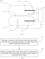
- the electronic anode 30 in a case where the electronic anode 30 is electrically connected to the corresponding container 10, the electronic anode 30 runs a start-up mode, on-off of a predetermined time duration is performed to the container 10 and the electronic anode 30 through the electronic control device 80, and the potential value in the container 10 is detected. After operating a detection period Tj with the predetermined time duration, the electronic anode 30 detects the potential value Ut at time point Tj. It is determined whether Ut is in the fault state. When the Ut is in the fault state, fault is directly processed by adopting one or more of execution actions in action at S3, action at S4, and action at S5.
- control switch 90 may disconnect the electrical connection between the electronic anode 30 and the container 10, may use the magnesium rod 20 to perform corrosion protection on the container 10, may transmit an alarm signal, and use other fault processing. Then, the container 10 can be protected by using the standby device, and the standby device may use a processing mode such as using a standby magnesium rod or an electronic anode to replace a fault device. When the Ut is normal, an adjustment mode is performed.
- the on-off time of the previous predetermined time duration is used for operation.
- a potential value U1 of the container 10 is detected when operation in a Tj has passed. It is detected whether the Ut is in the fault state. When the Ut is in the fault state, the fault is processed, and the standby device is used to protect the container 10.
- U1 is compared with a threshold value U0. In response to the U1 being greater than U0, the time duration of applying a voltage to the electronic anode 30 is reduced. In response to U1 being smaller than U0, the time duration of applying a voltage to the electronic anode 30 is increased. The next on-off of the predetermined time duration is performed in the next period.
- the potential value U1 of the container 10 is detected again after running for a Tj. Moreover, fault determination and identification and the on time duration adjustment are performed. Accordingly, the loop realizes the protection for the container 10.
- Another electronic anode 30 uses the same control method as the above-mentioned electronic anode 30, operates simultaneously, and independently protects the other container 10.
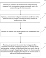
- the on-off of a predetermined time duration may be performed on the container 10 and the electronic anode 30 by the electronic control device 80, and the potential value in the container 10 may be detected.
- the electronic anode 30 runs a start-up mode A.
- the start-up mode A may be that an on-off of a predetermined time duration performed by the electronic control module is smaller than an on-off of a predetermined time duration of the start-up mode in the embodiment of FIG. 9 .
- the electronic anode 30 is switched into a start-up mode B.
- the start-up mode B may be that an on-off of a predetermined time duration performed by the electronic control module is greater than the on-off of the predetermined time duration of the start-up mode in the embodiment of FIG. 9 .
- a predetermined time duration of TB is run again and then the adjustment mode is entered. In a stage between running the start-up mode A and running the start-up mode B, fault determination and identification and processing are not performed.
- the on-off time of the previous predetermined time duration is used for operation.
- the potential value U1 of the container 10 is detected when operation in a potential value detection period Tj has passed. It is detected whether the Ut is in the fault state. When the Ut is in the fault state, the fault is processed and one or more of execution actions of action at S3, action at S4, and action at S5 is used.
- the control switch 90 may disconnect the electrical connection between the electronic anode 30 and the container 10, may use the magnesium rod 20 to perform corrosion protection on the container 10, may transmit an alarm signal, and use other fault processing.
- the container 10 is protected by using the standby device, and the standby device may use a processing mode such as using a standby magnesium rod or an electronic anode to replace a fault device.
- U1 When the Ut is normal, U1 is compared with the threshold value U0. In response to the U1 being greater than U0, the time duration of applying a voltage to the electronic anode 30 is reduced. In response to U1 being smaller than U0, the time duration of applying a voltage to the electronic anode 30 is increased. The next on-off of the predetermined time duration is performed in the next period. The potential value U1 of the container 10 is detected again after running for a Tj. Moreover, the fault determination and identification and the on time duration adjustment are performed. Accordingly, the loop realizes the protection for the container 10.
- Another electronic anode 30 uses the same control method as the above-mentioned electronic anode 30, operates simultaneously, and independently protects the other container 10.
- a water heater 100 includes a plurality of containers 10, a plurality of electronic anodes 30, and a controller (not shown).
- the plurality of containers 10 is in communication with each other.
- Each container 10 has at least one electronic anode 30 provided in the container 10.
- the controller is configured to implement the control method of the foregoing implementations.
- the water heater 100 has a controller capable of realizing a control method which includes adjusting and outputting the predetermined voltage applied to the electronic anode 30 by measuring a size of the potential value in the container 10 and stabilizing the potential value of the container 10 at the corrosion-stop level.
- a control method which includes adjusting and outputting the predetermined voltage applied to the electronic anode 30 by measuring a size of the potential value in the container 10 and stabilizing the potential value of the container 10 at the corrosion-stop level.
- the water heater 100 realizes a control method which includes adjusting and outputting the predetermined voltage applied to the electronic anode 30 based on the size of the measured potential value of the container 10 through a controller electrically connected to the plurality of containers and the plurality of electronic anodes.
- the electronic anode 30 inside the water heater 100 is electrically connected to the container 10.
- the electronic anode 30 is controlled by the controller to detect the potential value of the container 10.
- the controller determines whether the potential value is higher or lower than the predetermined value, and further perform control operations such as a predetermined voltage adjustment applied to the electronic anode 30.
- first and second are only used for descriptive purposes, and cannot be understood as indicating or implying relative importance or implicitly indicating the number of indicated technical features. Therefore, the features associated with “first” and “second” may explicitly or implicitly include at least one of the features. In the description of the present disclosure, "a plurality of” means at least two, such as two or three, unless otherwise specifically defined.
Landscapes
- Engineering & Computer Science (AREA)
- Chemical & Material Sciences (AREA)
- Mechanical Engineering (AREA)
- Physics & Mathematics (AREA)
- Metallurgy (AREA)
- Organic Chemistry (AREA)
- Materials Engineering (AREA)
- Thermal Sciences (AREA)
- Combustion & Propulsion (AREA)
- General Engineering & Computer Science (AREA)
- Computer Hardware Design (AREA)
- Prevention Of Electric Corrosion (AREA)
- Heat-Pump Type And Storage Water Heaters (AREA)
- Cookers (AREA)
Abstract
Description
- This application claims priorities to and rights of
Chinese Patent Applications No. 202221046904.4 202210455628.5, both filed before China National Intellectual Property Administration and on April 27, 2022 - The present disclosure relates to the technical field of water heaters, and particularly, to a water heater and a control method for a water heater.
- For a double-container electric water heater, it is customary to implement corrosion protection on two containers at the same time. In the related art, for the double-container electric water heater, the corrosion protection is performed on the two containers usually by adopting two magnesium rods. However, when the magnesium rod is used for performing corrosion protection on the container, the magnesium rod has a service life of generally only two years. When the magnesium rod is not replaced in time, the container is extremely prone to corrosion and water leakage.
- The present disclosure provides a water heater and a control method for a water heater.
- A water heater includes a plurality of containers and a plurality of electronic anodes. The plurality of containers is in communication with each other. Each container has at least one electronic anode provided in the container, and the electronic anode is capable of being electrically connected to the container.
- Optionally, each container of the water heater is electrically connected to the at least one electronic anode to serve as an anti-corrosion device for the container of the water heater. Compared with a traditional water heater that only adopts the magnesium rod to prevent corrosion of the container, a loss of the magnesium rod can be reduced. Moreover, the magnesium rod does not need to be frequently replaced. Therefore, occurrence of corrosion and water leakage in the container is lowered. Moreover, a service life of the container is prolonged.
- Optionally, the water heater further includes a plurality of magnesium rods. Each container has at least one magnesium rod provided in the container; and the container is electrically connected to the electronic anode or the magnesium rod in the same container.
- Optionally, each container has a mounting hole; the water heater includes a mounting member mounted in the mounting hole; and the magnesium rod and the electronic anode are each mounted on the mounting member.
- Optionally, the mounting member is provided with an insulating bottom support; and the electronic anode is fixed on the insulating bottom support.
- Optionally, a first insulating member is provided between the mounting member and an inner wall of the mounting hole; the first insulating member seals a gap between the mounting member and the mounting hole; and the first insulating member is disposed around the magnesium rod and the electronic anode.
- Optionally, the water heater further includes a pressing member connected to the container through a fastener and compressing the mounting member.
- Optionally, a second insulating member is provided between the pressing member and the mounting member.
- Optionally, a third insulating member is provided between the pressing member and the fastener.
- Optionally, the water heater further includes a heating member mounted on the mounting member and located in the container.
- Optionally, the water heater further includes a heating member mounted on the mounting member and located in the container.
- Optionally, the water heater further includes a plurality of switches and an electric control module. The plurality of switches has a one-to-one correspondence with the plurality of electronic anodes. The electric control module is configured to control position switching of at least one of the plurality of switches, so as to enable the electronic anode or the magnesium rod, which are provided in a same container, to be electrically connected to the container.
- Optionally, the electronic control module is configured to: in response to the electronic anode being electrically connected to the corresponding container, detect a potential value in the container through the electronic anode, and apply a predetermined voltage to the electronic anode based on the potential value. The potential value is inversely related to the predetermined voltage.
- Optionally, the electronic control module is further configured to: control, in response to the potential value being abnormal, the position switching of the switch to disconnect the electronic anode from the container and enable the magnesium rod to be electrically connected to the corresponding container; and/or stop applying a voltage to the electronic anode; and/or transmit an alarm signal of the corresponding container.
- Optionally, the electric control module is configured to: detect the potential value in the container every predetermined time duration; reduce, in response to the potential value being greater than a threshold, a time duration of applying a voltage to the electronic anode; and increase, in response to the potential value being smaller than the threshold, the time duration of applying the voltage to the electronic anode. The time duration of applying the voltage to the at least one of the plurality of the electronic anodes is equal to the predetermined time duration.
- Provided is a control method for a water heater. The water heater includes a plurality of containers and a plurality of electronic anodes. The plurality of containers is in communication with each other, and each container has electronic anode provided in the container. The control method includes: detecting, in response to the electronic anode being electrically connected to the corresponding container, a potential value in the container through the electronic anode; and applying a predetermined voltage to the electronic anode based on the potential value. The potential value is inversely related to the predetermined voltage.
- The control method for the water heater can adjust and output the predetermined voltage applied to the electronic anode based on the measured potential value in the container, to realize that the potential value of the container is stabilized at a corrosion-stop level. In this way, the container is protected to be stable and from corrosion. Meanwhile, improper application of the predetermined voltage on the electronic anode can be prevented. Further, a service life of the electronic anode and the service life of the container are prevented from being affected.
- Optionally, the control method further includes: controlling, in response to the potential value being abnormal, position switching of a switch to disconnect the electronic anode from the container and enable a magnesium rod to be electrically connected to a corresponding container; and/or stopping applying a voltage to the electronic anode; and/or transmitting an alarm signal of the corresponding container.
- Optionally, the control method further includes: detecting the potential value in the container every predetermined time duration; and reducing, in response to the potential value being greater than a threshold, a time duration of applying a voltage to the electronic anode; and increasing, in response to the potential value being smaller than the threshold, the time duration of applying the voltage to the electronic anode. The time duration of applying the voltage to the electronic anode is equal to the predetermined time duration.
- A water heater includes a plurality of containers, a plurality of electronic anodes, and a controller. The plurality of containers is in communication with each other. Each container has an electronic anode provided in the container. The controller is configured to implement the control method according to any one of the above implementations.
- The water heater has a controller capable of realizing a control method which includes adjusting and outputting the predetermined voltage applied to the electronic anode by measuring a size of the potential value in the container and stabilizing the potential value of the container at the corrosion-stop level. In this way, the plurality of containers of the water heater is protected to be stable and from corrosion. Meanwhile, the improper application of the predetermined voltage on the electronic anode can be prevented. Further, the service life of the electronic anode and the service life of the container are prolonged.
- Additional aspects and advantages of the present disclosure will be provided in part in the following description, or will become apparent in part from the following description, or can be learned from practicing of the present disclosure.
- The above and/or additional aspects and advantages of the present disclosure will become more apparent and more understandable from the following description of implementations taken in conjunction with the accompanying drawings.
-
FIG. 1 is a schematic structural view of a water heater according to an implementation of the present disclosure at a certain viewing angle. -
FIG. 2 is a schematic structural view of a water heater according to an implementation of the present disclosure at another viewing angle. -
FIG. 3 is a structural block diagram of a control switch of an electronic control module of a water heater according to an implementation of the present disclosure. -
FIG. 4 is a schematic plan view of an embodiment of a water heater according to an implementation of the present disclosure. -
FIG. 5 is a schematic plan view of another embodiment of a water heater according to an implementation of the present disclosure. -
FIG. 6 is a schematic flowchart of a control method for a water heater according to an implementation of the present disclosure. -
FIG. 7 is a schematic flowchart of a part of a control method for a water heater according to an implementation of the present disclosure. -
FIG. 8 is a schematic flowchart of another part of a control method for a water heater according to an implementation of the present disclosure. -
FIG. 9 is a schematic flowchart of an embodiment of a control method for a water heater according to an implementation of the present disclosure. -
FIG. 10 is a schematic flowchart of another embodiment of a control method for a water heater according to an implementation of the present disclosure. - Description of symbols of main elements are illustrated with drawings:
water heater 100,container 10, mountinghole 11,connection pipe 12,water inlet pipe 13,water outlet pipe 14,magnesium rod 20,electronic anode 30, mountingmember 40, insulatingbottom support 41, pressingmember 50, first insulatingmember 51, second insulatingmember 52, third insulatingmember 53,fastener 60,heating member 70,temperature measurer 71,electric control module 80,connection wire 81,switch 90. - Implementations of the present disclosure will be further described below with reference to the accompanying drawings. The same or similar elements, or elements having same or similar functions, are denoted by same or similar reference numerals in the drawings.
- In addition, the implementations of the present disclosure described below with reference to the drawings are illustrative, and are only intended to explain the implementations of the present disclosure, rather than limiting the present disclosure.
- In the present disclosure, unless expressly specified and defined otherwise, the first feature "on" or "under" the second feature may mean that the first feature is in direct contact with the second feature, or the first and second features are in indirect contact through an intermediate. Moreover, the first feature "above" the second feature may mean that the first feature is directly above or obliquely above the second feature, or simply mean that the level of the first feature is higher than that of the second feature. The first feature "below" the second feature may mean that the first feature is directly below or obliquely below the second feature, or simply mean that the level of the first feature is smaller than that of the second feature.
- Referring to
FIG. 1 andFIG. 2 , thewater heater 100 according to an implementation of the present disclosure includes a plurality ofcontainers 10 and a plurality ofelectronic anodes 30. The plurality ofcontainers 10 is in communication with each other. Eachcontainer 10 has at least oneelectronic anode 30 provided in thecontainer 10. Theelectronic anode 30 is capable of being electrically connected to thecontainer 10. - In some implementations, the
water heater 100 includes a plurality ofmagnesium rods 20. Eachcontainer 10 has at least onemagnesium rod 20 provided in thecontainer 10. In asame container 10, one of theelectronic anode 30 or themagnesium rod 20 is electrically connected to thecontainer 10. - According to the implementations of the present disclosure, each
container 10 of thewater heater 100 is electrically connected with at least onemagnesium rod 20 and at least oneelectronic anode 30 to serve as an anti-corrosion device for thecontainer 10 of thewater heater 100. Compared with atraditional water heater 100 that only adopts themagnesium rod 20 to prevent corrosion of thecontainer 10, a loss of themagnesium rod 20 can be reduced. Moreover, themagnesium rod 20 does not need to be frequently replaced. Therefore, occurrence of corrosion and water leakage in thecontainer 10 is lowered. Moreover, a service life of thecontainer 10 is prolonged. - In an exemplary embodiment of the present disclosure, the
container 10 of thewater heater 100 may be of a long-barrel-shaped structure on thewater heater 100 that has characteristics such as water storage and heat preservation, and may be anenamel container 10, a stainless-steel container 10, or the like. For example, thewater heater 100 may have twocontainers 10. When thewater heater 100 has twocontainers 10, the twocontainers 10 may be in communication with each other and make an internal communication between the twocontainers 10 in a pipeline connection manner. Asingle container 10 may be respectively provided with a water inlet pipeline and a water outlet pipeline at two sides of thecontainer 10. Pipelines at a side where the twocontainers 10 are connected to each other may be in communication with each other and may be connected to each other through a rigid pipe, a hose, or other water pipes. In this way, one of the pipelines of the twocontainers 10 facing away from the side where the twocontainers 10 are connected to each other can be awater inlet pipe 13, and the other one of the pipelines of the twocontainers 10 facing away from the side where the twocontainers 10 are connected to each other can be awater outlet pipe 14. - Further, when the
water heater 100 is awater heater 100 with a double-container 10. Eachcontainer 10 may be provided with onemagnesium rod 20 and oneelectronic anode 30. Each of themagnesium rod 20 and theelectronic anode 30 may be of a cylindrical structure. Themagnesium rod 20 and theelectronic anode 30 may be inserted into a cavity of thecontainer 10 at the same time and may be electrically connected to thecontainer 10 at the same time. Themagnesium rod 20 may be a metal rod primarily composed of magnesium element, may serve as a sacrificial anode in thewater heater 100, and may protect a cathode as thecontainer 10. Similarly, theelectronic anode 30 may be of a cylindrical rod-shaped structure that predominantly composed of conductive element and is capable of connecting to a power source. For example, theelectronic anode 30 may be a pure titaniumelectronic anode 30. Moreover, theelectronic anode 30 may release anode ions by being connected to the power source and may protect the cathode as thecontainer 10. - Referring to
FIG. 1 andFIG. 2 , in some implementations, eachcontainer 10 has a mountinghole 11. Thewater heater 100 includes a mountingmember 40 that is mounted in the mountinghole 11. Themagnesium rod 20 and theelectronic anode 30 are each mounted on the mountingmember 40. - In this way, the mounting
hole 11 of thecontainer 10 can be used for accommodating themagnesium rod 20 and theelectronic anode 30. The mountingmember 40 may provide a common mounting component for themagnesium rod 20 and theelectronic anode 30. Themagnesium rod 20 and theelectronic anode 30 are mounted on the mountingmember 40, thereby facilitating synchronous and convenient mounting of themagnesium rod 20 and theelectronic anode 30 into the mountinghole 11 of thecontainer 10. - In an exemplary embodiment of the present disclosure, the mounting
hole 11 of thecontainer 10 may be located at an end of thecontainer 10 in a length direction of thecontainer 10. The mountinghole 11 may be located at an opening of thecontainer 10. The mountinghole 11 may have a circular or elliptical cross section. A size of an aperture of the mountinghole 11 may be greater than that of an end of the mountingmember 40 on which themagnesium rod 20 and theelectronic anode 30 are mounted. In this way, insertion of each of themagnesium rod 20 and theelectronic anode 30 on the mountingmember 40 can be facilitated. The mountingmember 40 may be a disc-shaped part, may be used for mounting and fixing themagnesium rod 20 and theelectronic anode 30, and may be connected to a position of the mountinghole 11 of thecontainer 10 and may seal the connection position. For example, the mountingmember 40 may be a flat welding flange, a threaded flange, and the like. - The mounting
member 40 may be of a flat disc-shaped structure. The mountingmember 40 may be reserved with a part that is connected to a device such as themagnesium rod 20 and theelectronic anode 30. Themagnesium rod 20 may be connected to the mountingmember 40 in a direction vertical to a plane where the mountingmember 40 is located. Themagnesium rod 20 may be fixedly connected to the mountingmember 40 through screws. Similarly, theelectronic anode 30 may also be connected to the mountingmember 40 in a direction vertical to the plane where the mountingmember 40 is located. A connection manner between theelectronic anode 30 and the mountingmember 40 may be a fixed connection through a fixing base. - Referring to
FIG. 1 andFIG. 2 , in some implementations, the mountingmember 40 is provided with an insulatingbottom support 41. Theelectronic anode 30 is fixed on the insulatingbottom support 41. - The insulating
bottom support 41 has an insulation characteristic, which can isolate theelectronic anode 30 from the mountingmember 40. The insulatingbottom support 41 may improve a level position of theelectronic anode 30 away from the mountinghole 11 of thecontainer 10. The insulatingbottom support 41 may cause theelectronic anode 30 to be unable to be directly connected to thecontainer 10 after deposition of magnesium shavings, water scale, or the like resulting from long-term use of themagnesium rod 20 and theelectronic anode 30. - In an exemplary embodiment of the present disclosure, the insulating
bottom support 41 may be made of an insulation material, which may be rubber, plastic, or the like. The insulatingbottom support 41 may be of a circular-ring columnar structure. Theelectronic anode 30 may be fixed to a middle part of the insulatingbottom support 41. The insulatingbottom support 41 may be disposed between theelectronic anode 30 and the mountingmember 40. Theelectronic anode 30 may be fixed on the insulatingbottom support 41. Further, theelectronic anode 30 is fixed on the mountingmember 40 through the insulatingbottom support 41 again. - Referring to
FIG. 1 andFIG. 2 , in some implementations, a first insulatingmember 51 is provided between the mountingmember 40 and an inner wall of the mountinghole 11. The first insulatingmember 51 seals a gap between the mountingmember 40 and the mountinghole 11. The first insulatingmember 51 is disposed around themagnesium rod 20 and theelectronic anode 30. - The first insulating
member 51 is disposed between the mountingmember 40 and the mountinghole 11 of thecontainer 10, which can isolate thecontainer 10 from the mountingmember 40, to ensure insulation of a contact position between the mountinghole 11 of thecontainer 10 and the mountingmember 40. Therefore, conduction between thecontainer 10 and the mountingmember 40 caused by an insulation problem is avoided. Moreover, operation stability of the heater is improved. - In an exemplary embodiment of the present disclosure, the first insulating
member 51 may be a basin-shaped member made of an insulation material such as rubber. Themagnesium rod 20 and theelectronic anode 30 may pass through the first insulatingmember 51 and the first insulatingmember 51 is sandwiched between the mountingmember 40 and the mountinghole 11 of thecontainer 10. Further, an end that faces away from the mountingmember 40 and is mounted with themagnesium rod 20 and theelectronic anode 30 may be placed into thecontainer 10 from the mountinghole 11 of thecontainer 10. The mountingmember 40 may be attached to the mountinghole 11 of thecontainer 10. Two surfaces of an edge of the first insulatingmember 51 may be tightly attached to thecontainer 10 and the mountingmember 40, respectively. - Referring to
FIG. 1 andFIG. 2 , in some implementations, thewater heater 100 further includes a pressingmember 50. The pressingmember 50 is connected to thecontainer 10 throughfasteners 60 and presses the mountingmember 40. - In this way, the pressing
member 50 can press an upper end surface of the mountingmember 40 and press the mountingmember 40 at the position of the mountinghole 11 of thecontainer 10 under the action of thefastener 60. In addition, the pressingmember 50 may provide functions of mounting and pressing, such that the mountingmember 40 can be made better pressed and mounted at the position of the mountinghole 11 of thecontainer 10. - In an exemplary embodiment of the present disclosure, the pressing
member 50 may match a shape and structure of the mountingmember 40. The pressingmember 50 may be matched and attached with the mountingmember 40. The mountingmember 40 and the pressingmember 50 can be tightly pressed together under fastening of thefastener 60, and the mountingmember 40 and the pressingmember 50 can be pressed and fixed at the position of mountinghole 11 of thecontainer 10 under the fastening of thefastener 60. - Referring to
FIG. 1 andFIG. 2 , in some implementations, a second insulatingmember 52 is provided between the pressingmember 50 and the mountingmember 40. - In this way, the second insulating
member 52 can isolate the mountingmember 40 from the pressingmember 50, to ensure insulativity between thecontainer 10 and the mountingmember 40. Moreover, the second insulatingmember 52 can also protect sealing of a part of the mountingmember 40 facing towards the pressingmember 50. - In an exemplary embodiment of the present disclosure, the second insulating
member 52 may have a similarly structural form to that of the mountingmember 40 and the pressingmember 50. The second insulatingmember 52 may be in a flat shape and may have a certain contact area and thickness. The second insulatingmember 52 may be made of an insulation material such as rubber or plastic. The second insulatingmember 52 may sandwiched between the mountingmember 40 and the pressingmember 50. The pressingmember 50 may first press the mountingmember 40 at intervals through the second insulatingmember 52, and then press and mount the mountingmember 40 at the position of the mountinghole 11 of thecontainer 10 through thefastener 60. - Referring to
FIG. 1 andFIG. 2 , in some implementations, a third insulatingmember 53 is disposed between the pressingmember 50 and thefastener 60. - In this way, the third insulating
member 53 can be sandwiched between the pressingmember 50 and thefastener 60, to allow thefastener 60 to be spaced apart from the pressingmember 50 and the mountingmember 40. Therefore, thefastener 60 is allowed to be only in a contact connection with an exterior of thecontainer 10. Moreover, the insulativity between thecontainer 10 and the mountingmember 40 can be ensured. - In an exemplary embodiment of the present disclosure, the
fastener 60 may be a fixing device for fastening the pressingmember 50 and the mountingmember 40 at the same time to the position of the mountinghole 11 of thecontainer 10 through a fastening position on the pressingmember 50. Thefastener 60 may adopt a connection fastening manner of a stud and a nut. For example, when thefastener 60 is in a fastening manner in which the stud and the nut are fitted to each other, the stud may be disposed around the mountinghole 11 of thecontainer 10. Then, the third insulatingmember 53 may be inserted into the fastening position of the pressingmember 50 and the mountingmember 40, and then pass through the stud. Further, the pressingmember 50 and the mountingmember 40 may be pressed and mounted at the position of the mountinghole 11 of thecontainer 10 through a threaded fastening connection between the nut and the stud - Referring to
FIG. 1 andFIG. 2 , in some implementations, thewater heater 100 further includes aheating member 70. Theheating member 70 is mounted on the mountingmember 40 and located in thecontainer 10. In some implementations, thewater heater 100 further includes atemperature measurer 71. Thetemperature measurer 71 is mounted on the mountingmember 40 and located in thecontainer 10. In this way, thewater heater 100 may heat water stored in thecontainer 10 through theheating member 70 located in thecontainer 10, and may also monitor a temperature of the water stored in thecontainer 10 through thetemperature measurer 71 located in thecontainer 10. Further, functions of water temperature adjustment, energy conservation, and the like of thewater heater 100 can be realized. - In an exemplary embodiment of the present disclosure, the
heating member 70 of thewater heater 100 may be connected to the mountingmember 40. Theheating member 70 is located at a position on the mountingmember 40 close to themagnesium rod 20 and theelectronic anode 30. After energized, theheating member 70 can heat the water in thecontainer 10. Theheating member 70 may be a heating pipe made of stainless steel or a copper material. Further, the heating pipe may be in the form of a single-pipe heating pipe, a double-pipe heating pipe, a vortex-type heating pipe, or the like. Thetemperature measurer 71 may be a metal element having a temperature sensor. Thetemperature measurer 71 may be close to a position of theheating member 70 mounted on the mountingmember 40. In this way, measurement of a water temperature in the core of thecontainer 10 can be facilitated. - Referring to
FIG. 3 to FIG. 5 , in some implementations, thewater heater 100 includes a plurality ofswitches 90 and anelectronic control module 80. The plurality ofswitches 90 has a one-to-one correspondence with the plurality ofelectronic anodes 30. Theelectronic control module 80 is configured to control position switching of at least one of the plurality ofswitches 90, enabling one of theelectronic anode 30 and themagnesium rod 20 in asame container 10 to be electrically connected to thecontainer 10. - In the
water heater 100, theswitch 90 can be controlled through theelectronic control module 80. In different cases, an anode or anelectronic anode 30 may be sacrificed to perform corrosion protection on thecontainer 10. Therefore, purposes of reducing a loss of the sacrificial anode, prolonging the service life of thecontainer 10, and lowering water pollution are realized. - In an exemplary embodiment of the present disclosure, the
water heater 100 may be a double-container water heater 100. The double-container water heater 100 may have twocontainers 10. When thewater heater 100 is a double-container water heater 100, oneelectric control module 80 may be provided for thewater heater 100. The oneelectronic control module 80 may control theswitch 90, and twoswitches 90 may be provided, i.e., oneelectronic control module 80 may control the two switches 90. One of the twoswitches 90 may control an electrical connection of onecontainer 10 in the double-container water heater 100 to themagnesium rod 20 and theelectronic anode 30 in thecontainer 10. Similarly, the other one of the twoswitches 90 may control an electrical connection of theother container 10 in the double-container water heater 100 to themagnesium rod 20 and theelectronic anode 30 in thecontainer 10. - Referring to
FIG. 3 to FIG. 5 , in some implementations, theelectronic control module 80 is configured to: in response to theelectronic anode 30 being electrically connected to the correspondingcontainer 10, detect a potential value in thecontainer 10 through theelectronic anode 30, and apply a predetermined voltage to theelectronic anode 30 based on the potential value. The potential value is inversely related to the predetermined voltage. - In this way, the
electronic control module 80 adjusts and outputs the predetermined voltage applied to theelectronic anode 30 based on a size of the measured potential value in thecontainer 10. Therefore, it can be realized that the potential value of thecontainer 10 is stabilized at a corrosion-stop level, to protect thecontainer 10 to be stable and from being corroded. Meanwhile, an improper predetermined voltage can be prevented from being applied to theelectronic anode 30. Further, a service life of theelectronic anode 30 and the service life of thecontainer 10 are prolonged. - In an exemplary embodiment of the present disclosure, in one embodiment (as illustrated in
FIG. 4 ), thewater heater 100 may be an upright double-container water heater 100. When the upright double-container water heater 100 is used, twocontainers 10 are vertically arranged and installed side by side. Moreover, bottoms of the twocontainers 10 may be connected to each other through aconnection pipe 12. An end of acontainer 10 may be mounted with anelectronic anode 30 and amagnesium rod 20. An end of theother container 10 may be mounted with anelectronic anode 30 and amagnesium rod 20. Thecontainer 10, theelectronic anode 30, and themagnesium rod 20 may be each electrically connected to theelectronic control module 80 through theconnection wire 81. - In another embodiment (as illustrated in
FIG. 5 ), thewater heater 100 may be a horizontal double-container water heater 100. When the horizontal double-container water heater 100 is used, anupper container 10 and alower container 10 are horizontally installed side by side. Moreover, middle parts of theupper container 10 and thelower container 10 are connected through twoconnection pipes 12. Anelectronic anode 30 and amagnesium rod 20 may be mounted at an end of acontainer 10. Anelectronic anode 30 may be mounted at an end of theother container 10 and amagnesium rod 20 may be mounted on a lower part of theother container 10. Thecontainer 10, theelectronic anode 30, and themagnesium rod 20 may each be electrically connected to theelectronic control module 80 through theconnection wire 81. - After the two
containers 10 are filled with water, a voltage may be inputted to theelectric control module 80, with a numerical value ranging from 3V to 10V. Theelectric control module 80 may be started. Theelectric control module 80 may control a relay, to enable thecontainer 10 to be communicated with theelectronic anode 30, and output the predetermined voltage with a numerical value in a range from 0.2V to 8V A tank pressure is applied to theelectronic anode 30 and thecontainer 10. Cathode polarization currents are provided to the twocontainers 10, respectively. Theelectric control module 80 adjusts an output voltage on theelectronic anode 30 based on the measured potential value, which enables each of the potential values of the twocontainers 10 to be stabilized at the corrosion-stop level. - The potential value is inversely related to the predetermined voltage. It can be understood that, for example, when the potential value of the
container 10 measured by theelectronic control module 80 is 900 mV, it indicates a stable corrosion-stop level. When the potential value of thecontainer 10 measured by theelectronic control module 80 is smaller than 900 mV, thecontainer 10 may be susceptible to corrosion. Moreover, theelectronic control module 80 may adjust the predetermined voltage inputted to theelectronic anode 30, such as raising from 500 mV to 1000 mV. Therefore, theelectronic anode 30 can improve its output, enabling the potential value of thecontainer 10 to be increased to 900 mV, and thecontainer 10 can be at the stable corrosion-stop level. Similarly, when the potential value of thecontainer 10 measured by theelectronic control module 80 is greater than 900 mV, thecontainer 10 can be susceptible to corrosion. Theelectronic control module 80 can adjust the predetermined voltage inputted to theelectronic anode 30, such as reducuing from 1000 mV to 500 mV. Therefore, theelectronic anode 30 can reduce the output, enabling the potential value of thecontainer 10 to be reduced to 900 mV. Moreover, thecontainer 10 can be at the stable corrosion-stop level. - Referring to
FIG. 3 to FIG. 5 , in some implementations, theelectronic control module 80 is further configured to: control, in response to the potential value being abnormal, the position switching of theswitch 90 to disconnect theelectronic anode 30 from thecontainer 10, and enable themagnesium rod 20 to be electrically connected to the correspondingcontainer 10; and/or stop applying a voltage to theelectronic anode 30; and/or transmit an alarm signal of the correspondingcontainer 10. - In this way, the
water heater 100 can control theswitch 90 to disconnect an electrical connection between theelectronic anode 30 and thecontainer 10 by theelectronic control module 80 detecting abnormity of the potential value, e.g., in cases where thewater heater 100 is powered off, where theelectronic anode 30 fails, and the like. Themagnesium rod 20 is used to perform corrosion protection on thecontainer 10 and an alarm signal is transmitted. In this way, the purpose of reducing the loss of themagnesium rod 20, prolonging the service life of thecontainer 10, and lowering the water pollution can be realized. Theelectronic control module 80 is configured to transmit an alarm signal to improve safety during operation of thewater heater 100. - In an exemplary embodiment of the present disclosure, when the
electric control module 80 detects that a potential value of one of thecontainers 10 is in a fault state, theelectric control module 80 may immediately stop outputting the predetermined voltage to theelectronic anode 30 in thecontainer 10, and then process a fault of an assembly of thecontainer 10 and theelectronic anode 30. Theelectronic anode 30 may be disconnected from thecontainer 10 and themagnesium rod 20 may be connected to thecontainer 10, such that themagnesium rod 20 is used for performing corrosion protection on thecontainer 10. At the same time, theelectric control module 80 may also transmit an alarm signal synchronously and independently. It can be understood that theelectronic anode 30 in theother container 10 and theother container 10 are unaffected, and theelectronic anode 30 continuously protects theother container 10. - For example, when the
electric control module 80 is powered off or the potentials of the twocontainers 10 are each detected to be in the fault state, the twoelectronic anodes 30 are disconnected from the twocontainers 10. Moreover, the twocontainers 10 are respectively connected to the correspondingmagnesium rods 20, to continuously protect the twocontainers 10. - For example, when the potential value of the
container 10 exceeds 1200 mV, it indicates that thecontainer 10 is in the fault state. When theelectronic control module 80 detects that the potential value of thecontainer 10 exceeds 1200 mV, the electronic control device may output the predetermined voltage that is lowered to zero theelectronic anode 30 in thecontainer 10 and transmit an alarm signal. Moreover, the electronic control device may further control theswitch 90 to disconnect the connection between theelectronic anode 30 and thecontainer 10. - Referring to
FIG. 3 to FIG. 5 , in some implementations, theelectronic control module 80 is configured to: detect the potential value in thecontainer 10 every predetermined time duration; reduce, in response to the potential value being greater than a threshold, a time duration of applying a voltage to theelectronic anode 30; and increase, in response to the potential value being smaller than the threshold, the time duration of applying the voltage to theelectronic anode 30. The time duration of applying the voltage to theelectronic anode 30 is equal to the predetermined time duration. - In this way, the
electronic control module 80 further adjusts a time duration of the voltage applied to theelectronic anode 30 based on a comparison between a threshold and the potential value detected by thecontainer 10 within a predetermined time duration, to stabilize the potential value of thecontainer 10 at the corrosion-stop level. Therefore, thecontainer 10 is protected to be stable and from being corroded. Meanwhile, application of an abnormal time duration of the voltage on theelectronic anode 30 can be prevented. Further, the service life of theelectronic anode 30 and the service life of thecontainer 10 are affected. - In an exemplary embodiment of the present disclosure, after the two
containers 10 are filled with water, theelectric control module 80 may detect the potential value of thecontainer 10 in the predetermined time duration. For example, a threshold of the potential value may be 900 mV. Theelectric control module 80 may keep the potential value of thecontainer 10 stable at the threshold when applying a fixed voltage of 1000 mV to theelectronic anode 30 for a time duration of 5 minutes. When theelectric control module 80 detects that the potential value of thecontainer 10 is 1200 mV within 5 minutes, the potential value of thecontainer 10 is greater than the threshold. Moreover, theelectric control module 80 may maintain the fixed voltage of 1000 mV applied to theelectronic anode 30 for a voltage time duration smaller than 5 minutes. In this way, the potential value of thecontainer 10 can be lowered to a threshold state of 900 mV. Similarly, when theelectric control module 80 detects that the potential value of thecontainer 10 is 700 mV within 5 minutes, the potential value of thecontainer 10 is smaller than the threshold. In addition, theelectric control module 80 may maintain a voltage of 1000 mV applied to theelectronic anode 30 for a voltage time duration greater than 5 minutes. In this way, the potential value of thecontainer 10 can be increased to a threshold state of 900 mV. - Referring to
FIG. 6 , in a control method for awater heater 100 according to the implementations of the present disclosure, thewater heater 100 includes a plurality ofcontainers 10 and a plurality ofelectronic anodes 30. The plurality ofcontainers 10 is in communication with each other. Eachcontainer 10 has at least oneelectronic anode 30 provided in thecontainer 10. The control method includes the following actions. - At S1, in response to the
electronic anode 30 being electrically connected to the correspondingcontainer 10, a potential value in thecontainer 10 is detected through theelectronic anode 30. - At S2, a predetermined voltage is applied to the
electronic anode 30 based on the potential value. The potential value is inversely related to the predetermined voltage. - According to the implementations of the present disclosure, the control method for the
water heater 100 may adjust and output the predetermined voltage applied to theelectronic anode 30 based on the size of the measured potential value in thecontainer 10, to realize that the potential value of thecontainer 10 is stabilized at the corrosion-stop level. Therefore, thecontainer 10 is protected to be stable and from being corroded. Meanwhile, the improper predetermined voltage can be prevented from being applied to theelectronic anode 30. Further, the service life of theelectronic anode 30 and the service life of thecontainer 10 are affected. - In an exemplary embodiment of the present disclosure, the
electronic anode 30 is electrically connected to thecontainer 10. Then, the potential value of thecontainer 10 is detected by theelectronic anode 30. Further, the predetermined voltage applied to theelectronic anode 30 is adjusted by determining whether the potential value is higher or lower than a predetermined value. When the potential value is higher than the predetermined value, the predetermined voltage is lowered. When the potential value is lower than the predetermined value, the predetermined voltage is increased. The potential value is inversely related to the predetermined voltage. - Referring to
FIG. 7 , in some implementations, the control method further includes the following actions. - At S3, in response to the potential value being abnormal, position switching of a
switch 90 is controlled to disconnect theelectronic anode 30 from thecontainer 10 and enable amagnesium rod 20 to be electrically connected to a correspondingcontainer 10; and/or - At S4, a voltage applied to the
electronic anode 30 is stopped; and/or - At S5, an alarm signal of the corresponding
container 10 is transmitted. - In this way, the
water heater 100 can control theswitch 90 to disconnect the electrical connection between theelectronic anode 30 and thecontainer 10 by theelectronic control module 80 detecting the abnormality of the potential value, e.g., in a case where thewater heater 100 is powered off, where theelectronic anode 30 fails, and the like. Themagnesium rod 20 is used for performing corrosion protection on thecontainer 10 and an alarm signal is transmitted. In this way, the purpose of reducing the loss of themagnesium rod 20, prolonging the service life of thecontainer 10, and lowering water pollution can be achieved. Theelectronic control module 80 may also transmit an alarm signal to improve the safety during the use of thewater heater 100. - In an exemplary embodiment of the present disclosure, after the potential value of the
container 10 is detected through theelectronic anode 30 in the actions (at S1 and S2), it may be further determined whether the potential value is in an abnormal state. Then, the electrical connection between theelectronic anode 30 and thecontainer 10 may be disconnected and a connection between themagnesium rod 20 and the correspondingcontainer 10 may be switched into synchronously by controlling the position of theswitch 90. Then, the predetermined voltage may be stopped from being applied to theelectronic anode 30. Further, an alarm signal may be transmitted for the correspondingcontainer 10 - Further, it can be understood that, after the electronic control module detects and determines that the potential value is in the abnormal state, one of, two of, or all of action at S3, action at S4, and action at S5 may be performed. For example, the abnormal potential value of the
container 10 is greater than 2000m V. When theelectrical control module 80 detects that the potential value of thecontainer 10 is 2500 mV, one of action at S3, action at S4, and action at S5 may be performed, i.e., theelectronic control module 80 may control acontrol switch 90 to disconnect the electrical connection between theelectronic anode 30 and thecontainer 10 and be switched into a connection between themagnesium rod 20 and the correspondingcontainer 10 or stop applying a predetermined voltage to theelectronic anode 30 or transmit an alarm signal for the correspondingcontainer 10. - Similarly, two of aciton at S3, action at S4 and action at S5 may be performed, i.e., the
electronic control module 80 may control thecontrol switch 90 to disconnect the electrical connection between theelectronic anode 30 and thecontainer 10 and be switched into a connection between themagnesium rod 20 and the correspondingcontainer 10 and stop applying a predetermined voltage to theelectronic anode 30. Alternatively, theelectronic control module 80 may control thecontrol switch 90 to disconnect the electrical connection between theelectronic anode 30 and thecontainer 10 and be switched into a connection between themagnesium rod 20 and the correspondingcontainer 10 and transmit an alarm signal for the correspondingcontainer 10 at the same time. Alternatively, theelectronic control module 80 stops applying a predetermined voltage to theelectronic anode 30 and transmits an alarm signal for the correspondingcontainer 10 at the same time. - Similarly, all of action at S3, action at S4, and action at S5 may be performed, i.e., the
electronic control module 80 may control thecontrol switch 90 to disconnect the electrical connection between theelectronic anode 30 and thecontainer 10 and be switched into a connection between themagnesium rod 20 and the correspondingcontainer 10, and stop applying a predetermined voltage to theelectronic anode 30, and transmit an alarm signal for the correspondingcontainer 10 at the same time. - Referring to
FIG. 8 , in some implementations, the control method further includes the following actions. - At S6, the potential value in the
container 10 is detected every predetermined time duration. - At S7, in response to the potential value being greater than a threshold, a time duration of applying a voltage to the
electronic anode 30 is reduced and a time duration of applying the voltage to theelectronic anode 30 is equal to the predetermined time duration. In response to the potential value being smaller than the threshold, the time duration of applying the voltage to theelectronic anode 30 is increased and a time duration of applying the voltage to theelectronic anode 30 is equal to the predetermined time duration. - In this way, the
electronic anode 30 serves as a reference electrode and measures real-time potential of thecontainer 10 by taking a predetermined time duration as a interval. After comparing a measured potential value of thecontainer 10 with the threshold, the time duration of applying the voltage to theelectronic anode 30 is adjusted in time, such that the potential of thecontainer 10 is made at the corrosion-stop level. Moreover, the potential of thecontainer 10 can be dynamically adjusted and always maintained within a protection potential range by continuously the above actions in the loop. When a fault occurs, the fault can be identified and a fault mode is entered. Moreover, the fault is processed, and a standby device is used to protect thecontainer 10, enabling thecontainer 10 to be each protected in various cases. Moreover, operation processes of the plurality ofelectronic anodes 30 are independent from each other and do not interfere with each other. Therefore, the plurality ofcontainers 10 can be protected concurrently. - In an exemplary embodiment of the present disclosure, the potential value in the
container 10 may be detected once within a predetermined time duration. Then, the time duration of applying the voltage to theelectronic anode 30 may be reduced in response to the potential value being greater than the threshold. The time duration of applying the voltage to theelectronic anode 30 may be increased in response to the potential value being smaller than the threshold. At this time, the time duration of applying the voltage to theelectronic anode 30 is equal to the predetermined time duration. - In an implementation (as illustrated in
FIG. 9 and referring toFIG. 3 to FIG. 5 ), in a case where theelectronic anode 30 is electrically connected to the correspondingcontainer 10, theelectronic anode 30 runs a start-up mode, on-off of a predetermined time duration is performed to thecontainer 10 and theelectronic anode 30 through theelectronic control device 80, and the potential value in thecontainer 10 is detected. After operating a detection period Tj with the predetermined time duration, theelectronic anode 30 detects the potential value Ut at time point Tj. It is determined whether Ut is in the fault state. When the Ut is in the fault state, fault is directly processed by adopting one or more of execution actions in action at S3, action at S4, and action at S5. For example, thecontrol switch 90 may disconnect the electrical connection between theelectronic anode 30 and thecontainer 10, may use themagnesium rod 20 to perform corrosion protection on thecontainer 10, may transmit an alarm signal, and use other fault processing. Then, thecontainer 10 can be protected by using the standby device, and the standby device may use a processing mode such as using a standby magnesium rod or an electronic anode to replace a fault device. When the Ut is normal, an adjustment mode is performed. - In the adjustment mode, the on-off time of the previous predetermined time duration is used for operation. A potential value U1 of the
container 10 is detected when operation in a Tj has passed. It is detected whether the Ut is in the fault state. When the Ut is in the fault state, the fault is processed, and the standby device is used to protect thecontainer 10. When the Ut is normal, U1 is compared with a threshold value U0. In response to the U1 being greater than U0, the time duration of applying a voltage to theelectronic anode 30 is reduced. In response to U1 being smaller than U0, the time duration of applying a voltage to theelectronic anode 30 is increased. The next on-off of the predetermined time duration is performed in the next period. The potential value U1 of thecontainer 10 is detected again after running for a Tj. Moreover, fault determination and identification and the on time duration adjustment are performed. Accordingly, the loop realizes the protection for thecontainer 10. - Another
electronic anode 30 uses the same control method as the above-mentionedelectronic anode 30, operates simultaneously, and independently protects theother container 10. - In another embodiment (as illustrated in
FIG. 10 and referring toFIG. 3 to FIG. 5 ), in a case where theelectronic anode 30 is electrically connected to the correspondingcontainer 10, the on-off of a predetermined time duration may be performed on thecontainer 10 and theelectronic anode 30 by theelectronic control device 80, and the potential value in thecontainer 10 may be detected. Theelectronic anode 30 runs a start-up mode A. The start-up mode A may be that an on-off of a predetermined time duration performed by the electronic control module is smaller than an on-off of a predetermined time duration of the start-up mode in the embodiment ofFIG. 9 . After running a predetermined time duration of TA, theelectronic anode 30 is switched into a start-up mode B. The start-up mode B may be that an on-off of a predetermined time duration performed by the electronic control module is greater than the on-off of the predetermined time duration of the start-up mode in the embodiment ofFIG. 9 . A predetermined time duration of TB is run again and then the adjustment mode is entered. In a stage between running the start-up mode A and running the start-up mode B, fault determination and identification and processing are not performed. - In the adjustment mode, the on-off time of the previous predetermined time duration is used for operation. The potential value U1 of the
container 10 is detected when operation in a potential value detection period Tj has passed. It is detected whether the Ut is in the fault state. When the Ut is in the fault state, the fault is processed and one or more of execution actions of action at S3, action at S4, and action at S5 is used. For example, thecontrol switch 90 may disconnect the electrical connection between theelectronic anode 30 and thecontainer 10, may use themagnesium rod 20 to perform corrosion protection on thecontainer 10, may transmit an alarm signal, and use other fault processing. Thecontainer 10 is protected by using the standby device, and the standby device may use a processing mode such as using a standby magnesium rod or an electronic anode to replace a fault device. When the Ut is normal, U1 is compared with the threshold value U0. In response to the U1 being greater than U0, the time duration of applying a voltage to theelectronic anode 30 is reduced. In response to U1 being smaller than U0, the time duration of applying a voltage to theelectronic anode 30 is increased. The next on-off of the predetermined time duration is performed in the next period. The potential value U1 of thecontainer 10 is detected again after running for a Tj. Moreover, the fault determination and identification and the on time duration adjustment are performed. Accordingly, the loop realizes the protection for thecontainer 10. - Another
electronic anode 30 uses the same control method as the above-mentionedelectronic anode 30, operates simultaneously, and independently protects theother container 10. - Referring to
FIG. 5 to FIG. 10 , awater heater 100 according to an implementation of the present disclosure includes a plurality ofcontainers 10, a plurality ofelectronic anodes 30, and a controller (not shown). The plurality ofcontainers 10 is in communication with each other. Eachcontainer 10 has at least oneelectronic anode 30 provided in thecontainer 10. The controller is configured to implement the control method of the foregoing implementations. - The
water heater 100 according to the implementations of the present disclosure has a controller capable of realizing a control method which includes adjusting and outputting the predetermined voltage applied to theelectronic anode 30 by measuring a size of the potential value in thecontainer 10 and stabilizing the potential value of thecontainer 10 at the corrosion-stop level. In this way, the plurality ofcontainers 10 of thewater heater 100 is protected to be stable and from corrosion. Meanwhile, the improper application of the predetermined voltage on theelectronic anode 30 can be prevented. Further, the service life of theelectronic anode 30 and the service life of thecontainer 10 are prolonged. - In an exemplary embodiment of the present disclosure, the
water heater 100 realizes a control method which includes adjusting and outputting the predetermined voltage applied to theelectronic anode 30 based on the size of the measured potential value of thecontainer 10 through a controller electrically connected to the plurality of containers and the plurality of electronic anodes. Theelectronic anode 30 inside thewater heater 100 is electrically connected to thecontainer 10. Then, theelectronic anode 30 is controlled by the controller to detect the potential value of thecontainer 10. Then, the controller determines whether the potential value is higher or lower than the predetermined value, and further perform control operations such as a predetermined voltage adjustment applied to theelectronic anode 30. - In the description of this specification, descriptions with reference to the terms "some implementations", "an implementation", "some implementations", "examples", "specific examples", or "some examples" etc., mean that specific features, structure, materials or characteristics described in conjunction with the embodiment or example are included in at least one embodiment or example of the present disclosure. In this specification, the schematic representations of the above terms do not necessarily refer to the same embodiment or example. Moreover, the described specific features, structures, materials or characteristics may be combined in any one or more embodiments or examples in a suitable manner. In addition, those skilled in the art can combine the different embodiments or examples and the features of the different embodiments or examples described in this specification without contradicting each other.
- In addition, the terms "first" and "second" are only used for descriptive purposes, and cannot be understood as indicating or implying relative importance or implicitly indicating the number of indicated technical features. Therefore, the features associated with "first" and "second" may explicitly or implicitly include at least one of the features. In the description of the present disclosure, "a plurality of" means at least two, such as two or three, unless otherwise specifically defined.
- Although embodiments according to the present disclosure have been shown and described, it would be appreciated by those skilled in the art that the above embodiments are illustrative and cannot be construed to limitation on the present disclosure, and changes, alternatives, modifications, and variations can be made in the embodiments without departing from scope of the present disclosure. The scope of the present disclosure is defined by the claims and their equivalents.
Claims (17)
- A water heater, comprising:a plurality of containers that are in communication with each other; anda plurality of electronic anodes, each container having at least one electronic anode provided in the container, and the electronic anode being capable of being electrically connected to the container.
- The water heater according to claim 1, further comprising a plurality of magnesium rods, wherein:each container has at least one magnesium rod provided in the container; andthe container is electrically connected to:
the electronic anode, or the magnesium rod in the same container. - The water heater according to claim 2, wherein:each container has a mounting hole;the water heater comprises a mounting member mounted in the mounting hole; andthe magnesium rod and the electronic anode are each mounted on the mounting member.
- The water heater according to claim 3, wherein:the mounting member is provided with an insulating bottom support; andthe electronic anode is fixed on the insulating bottom support.
- The water heater according to claim 3, wherein:a first insulating member is provided between the mounting member and an inner wall of the mounting hole;the first insulating member seals a gap between the mounting member and the mounting hole; andthe first insulating member is disposed around the magnesium rod and the electronic anode.
- The water heater according to claim 3, further comprising a pressing member connected to the container through a fastener and compressing the mounting member.
- The water heater according to claim 6, wherein a second insulating member is provided between the pressing member and the mounting member.
- The water heater according to claim 7, wherein a third insulation member is provided between the pressing member and the fastener.
- The water heater according to claim 3, further comprising a heating member mounted on the mounting member and located in the container.
- The water heater according to claim 1, further comprising:a plurality of switches having a one-to-one correspondence with a plurality of electronic anodes; andan electric control module configured to control position switching of at least one of the plurality of switches, so as to enable the electronic anode or the magnesium rod, which are provided in a same container to be electrically connected to the container.
- The water heater according to claim 10, wherein the electronic control module is configured to: in response to the electronic anode being electrically connected to the corresponding container, detect a potential value in the container through the electronic anode, and apply a predetermined voltage to the electronic anode based on the potential value, the potential value being inversely related to the predetermined voltage.
- The water heater according to claim 11, wherein the electronic control module is further configured to:control, in response to the potential value being abnormal, the position switching of the switch to disconnect the electronic anode from the container and enable the magnesium rod to be electrically connected to the corresponding container; and/orstop applying a voltage to the electronic anode; and/ortransmit an alarm signal of the corresponding container.
- The water heater according to claim 11, wherein the electric control module is configured to:detect the potential value in the container every predetermined time duration;reduce, in response to the potential value being greater than a threshold, a time duration of applying a voltage to the electronic anode; andincrease, in response to the potential value being smaller than the threshold, the time duration of applying the voltage to the electronic anode,wherein the time duration of applying the voltage to the electronic anode is equal to the predetermined time duration.
- A control method for a water heater, the water heater comprising a plurality of containers and a plurality of electronic anodes, the plurality of containers being in communication with each other, and each container having at least one of the plurality of electronic anodes provided in the container, the control method comprising:detecting, in response to the electronic anode being electrically connected to the corresponding container, a potential value in the container through the electronic anode; andapplying a predetermined voltage to the electronic anode based on the potential value, the potential value being inversely related to the predetermined voltage.
- The control method according to claim 14, further comprising:controlling, in response to the potential value being abnormal, position switching of a switch to disconnect the electronic anode from the container and enable a magnesium rod to be electrically connected to a corresponding container; and/orstopping applying a voltage to the electronic anode; and/ortransmitting an alarm signal of the corresponding container.
- The control method according to claim 14, further comprising:detecting the potential value in the container every predetermined time duration; andreducing, in response to the potential value being greater than a threshold, a time duration of applying a voltage to the electronic anodes and increasing, in response to the potential value being smaller than the threshold, the time duration of applying the voltage to the electronic anode, wherein the time duration of applying the voltage to the electronic anode is equal to the predetermined time duration.
- A water heater, comprising:a plurality of containers that is in communication with each other;a plurality of electronic anodes, each container having at least one of the plurality of electronic anodes provided in the container; anda controller configured to implement the control method according to any one of claims 14 to 16.
Applications Claiming Priority (3)
| Application Number | Priority Date | Filing Date | Title |
|---|---|---|---|
| CN202221046904.4U CN217464908U (en) | 2022-04-27 | 2022-04-27 | Insulating device, inner container assembly and water heater |
| CN202210455628.5A CN117006696A (en) | 2022-04-27 | 2022-04-27 | Water heaters and water heater control methods |
| PCT/CN2022/103081 WO2023206805A1 (en) | 2022-04-27 | 2022-06-30 | Water heater and control method for water heater |
Publications (2)
| Publication Number | Publication Date |
|---|---|
| EP4414625A1 true EP4414625A1 (en) | 2024-08-14 |
| EP4414625A4 EP4414625A4 (en) | 2025-03-26 |
Family
ID=88517103
Family Applications (1)
| Application Number | Title | Priority Date | Filing Date |
|---|---|---|---|
| EP22939633.8A Pending EP4414625A4 (en) | 2022-04-27 | 2022-06-30 | WATER HEATER AND WATER HEATER CONTROL METHOD |
Country Status (2)
| Country | Link |
|---|---|
| EP (1) | EP4414625A4 (en) |
| WO (1) | WO2023206805A1 (en) |
Family Cites Families (10)
| Publication number | Priority date | Publication date | Assignee | Title |
|---|---|---|---|---|
| DE3916847A1 (en) * | 1989-05-24 | 1990-11-29 | Norsk Hydro Magnesium | Electrical corrosion protection for water container - has e.g. water heater element as anode and container wall as cathode with pole-reversal protection diode between their connectors |
| ITAN20050037A1 (en) * | 2005-07-20 | 2007-01-21 | Merloni Termosanitari Spa | STORAGE WATER HEATER WITH ADJUSTABLE CATHODIC PROTECTION |
| US9803887B2 (en) * | 2013-06-24 | 2017-10-31 | Rheem Manufacturing Company | Cathodic corrosion and dry fire protection apparatus and methods for electric water heaters |
| CN104451702B (en) * | 2013-09-25 | 2018-06-05 | 珠海格力电器股份有限公司 | Water heater |
| CN208980798U (en) * | 2018-08-01 | 2019-06-14 | 广东格美淇电器有限公司 | A magnesium rod assembly for a water storage type electric water heater |
| CN211204441U (en) * | 2019-09-06 | 2020-08-07 | 芜湖美的厨卫电器制造有限公司 | Electron anode assembly and water heater |
| CN112815531A (en) * | 2019-11-15 | 2021-05-18 | 青岛海尔智能技术研发有限公司 | Anti-corrosion device for electric water heater and direct current electric water heater |
| CN211695424U (en) * | 2020-02-20 | 2020-10-16 | 芜湖美的厨卫电器制造有限公司 | An inner tank structure and a water storage type water heater |
| CN211695425U (en) * | 2020-02-20 | 2020-10-16 | 芜湖美的厨卫电器制造有限公司 | Inner tank structure and storage water heater |
| CN216206816U (en) * | 2021-11-09 | 2022-04-05 | 艾欧史密斯(中国)热水器有限公司 | Liquid level detection device, bladder and water heating device |
-
2022
- 2022-06-30 EP EP22939633.8A patent/EP4414625A4/en active Pending
- 2022-06-30 WO PCT/CN2022/103081 patent/WO2023206805A1/en not_active Ceased
Also Published As
| Publication number | Publication date |
|---|---|
| EP4414625A4 (en) | 2025-03-26 |
| WO2023206805A1 (en) | 2023-11-02 |
Similar Documents
| Publication | Publication Date | Title |
|---|---|---|
| US8068727B2 (en) | Storage-type water heater having tank condition monitoring features | |
| JP2016058254A (en) | Terminal block and power device | |
| EP4414625A1 (en) | Water heater and control method for water heater | |
| CN105331983A (en) | Control system and control method for forced current cathodic protection | |
| JPWO2016158830A1 (en) | Corrosion detection sensor, cooling device, cooling system, and vehicle power supply system | |
| CN105222363A (en) | A kind of water heater and safety protection control method thereof | |
| CN110208178B (en) | System and method for inhibiting and monitoring electrochemical corrosion of seawater piping systems | |
| CN108646109A (en) | Life detecting method, humidifier and computer-room air conditioning system for electrode humidifier | |
| US10731786B2 (en) | Fluid-conducting system with cathodic corrosion protection | |
| CN105910275B (en) | water heater | |
| CN213577428U (en) | Sterilizer electrothermal tube temperature control device | |
| CN217464908U (en) | Insulating device, inner container assembly and water heater | |
| RU2724655C1 (en) | Electric heating device with heating element with electric drive and anode for cathodic protection against corrosion | |
| CN117006696A (en) | Water heaters and water heater control methods | |
| JP5013089B2 (en) | Liquid level detector | |
| CN216868809U (en) | Water storage type water heater | |
| CN218210071U (en) | Electric water heater inner container and electric water heater | |
| KR101636071B1 (en) | Apparatus for hydroxyl radical generator | |
| CN212391738U (en) | Non-contact pressure controller for pump | |
| CN213182371U (en) | Dry-burning preventing device of sterilizer | |
| CN212299438U (en) | Electronic anode device and water heater | |
| CN113188250B (en) | Heating device, electric water heater and control method | |
| EP4253862A1 (en) | Water heater | |
| CN213630937U (en) | An anti-corrosion water heater | |
| CN215184658U (en) | a high voltage connector |
Legal Events
| Date | Code | Title | Description |
|---|---|---|---|
| STAA | Information on the status of an ep patent application or granted ep patent |
Free format text: STATUS: THE INTERNATIONAL PUBLICATION HAS BEEN MADE |
|
| PUAI | Public reference made under article 153(3) epc to a published international application that has entered the european phase |
Free format text: ORIGINAL CODE: 0009012 |
|
| STAA | Information on the status of an ep patent application or granted ep patent |
Free format text: STATUS: REQUEST FOR EXAMINATION WAS MADE |
|
| 17P | Request for examination filed |
Effective date: 20240508 |
|
| AK | Designated contracting states |
Kind code of ref document: A1 Designated state(s): AL AT BE BG CH CY CZ DE DK EE ES FI FR GB GR HR HU IE IS IT LI LT LU LV MC MK MT NL NO PL PT RO RS SE SI SK SM TR |
|
| A4 | Supplementary search report drawn up and despatched |
Effective date: 20250220 |
|
| RIC1 | Information provided on ipc code assigned before grant |
Ipc: C23F 13/22 20060101ALI20250214BHEP Ipc: C23F 13/06 20060101ALI20250214BHEP Ipc: F24H 15/421 20220101ALI20250214BHEP Ipc: F24H 9/20 20220101ALI20250214BHEP Ipc: F24H 9/00 20220101ALI20250214BHEP Ipc: F24H 9/45 20220101AFI20250214BHEP |
|
| DAV | Request for validation of the european patent (deleted) | ||
| DAX | Request for extension of the european patent (deleted) |