EP4414624A1 - Heat exchanger mounting structure and air conditioner - Google Patents
Heat exchanger mounting structure and air conditioner Download PDFInfo
- Publication number
- EP4414624A1 EP4414624A1 EP22899817.5A EP22899817A EP4414624A1 EP 4414624 A1 EP4414624 A1 EP 4414624A1 EP 22899817 A EP22899817 A EP 22899817A EP 4414624 A1 EP4414624 A1 EP 4414624A1
- Authority
- EP
- European Patent Office
- Prior art keywords
- heat exchanger
- installation
- side plate
- air duct
- flange
- Prior art date
- Legal status (The legal status is an assumption and is not a legal conclusion. Google has not performed a legal analysis and makes no representation as to the accuracy of the status listed.)
- Granted
Links
Images





Classifications
-
- F—MECHANICAL ENGINEERING; LIGHTING; HEATING; WEAPONS; BLASTING
- F28—HEAT EXCHANGE IN GENERAL
- F28D—HEAT-EXCHANGE APPARATUS, NOT PROVIDED FOR IN ANOTHER SUBCLASS, IN WHICH THE HEAT-EXCHANGE MEDIA DO NOT COME INTO DIRECT CONTACT
- F28D1/00—Heat-exchange apparatus having stationary conduit assemblies for one heat-exchange medium only, the media being in contact with different sides of the conduit wall, in which the other heat-exchange medium is a large body of fluid, e.g. domestic or motor car radiators
- F28D1/02—Heat-exchange apparatus having stationary conduit assemblies for one heat-exchange medium only, the media being in contact with different sides of the conduit wall, in which the other heat-exchange medium is a large body of fluid, e.g. domestic or motor car radiators with heat-exchange conduits immersed in the body of fluid
- F28D1/04—Heat-exchange apparatus having stationary conduit assemblies for one heat-exchange medium only, the media being in contact with different sides of the conduit wall, in which the other heat-exchange medium is a large body of fluid, e.g. domestic or motor car radiators with heat-exchange conduits immersed in the body of fluid with tubular conduits
- F28D1/047—Heat-exchange apparatus having stationary conduit assemblies for one heat-exchange medium only, the media being in contact with different sides of the conduit wall, in which the other heat-exchange medium is a large body of fluid, e.g. domestic or motor car radiators with heat-exchange conduits immersed in the body of fluid with tubular conduits the conduits being bent, e.g. in a serpentine or zig-zag
- F28D1/0477—Heat-exchange apparatus having stationary conduit assemblies for one heat-exchange medium only, the media being in contact with different sides of the conduit wall, in which the other heat-exchange medium is a large body of fluid, e.g. domestic or motor car radiators with heat-exchange conduits immersed in the body of fluid with tubular conduits the conduits being bent, e.g. in a serpentine or zig-zag the conduits being bent in a serpentine or zig-zag
-
- F—MECHANICAL ENGINEERING; LIGHTING; HEATING; WEAPONS; BLASTING
- F24—HEATING; RANGES; VENTILATING
- F24F—AIR-CONDITIONING; AIR-HUMIDIFICATION; VENTILATION; USE OF AIR CURRENTS FOR SCREENING
- F24F13/00—Details common to, or for air-conditioning, air-humidification, ventilation or use of air currents for screening
- F24F13/30—Arrangement or mounting of heat-exchangers
-
- F—MECHANICAL ENGINEERING; LIGHTING; HEATING; WEAPONS; BLASTING
- F24—HEATING; RANGES; VENTILATING
- F24F—AIR-CONDITIONING; AIR-HUMIDIFICATION; VENTILATION; USE OF AIR CURRENTS FOR SCREENING
- F24F1/00—Room units for air-conditioning, e.g. separate or self-contained units or units receiving primary air from a central station
- F24F1/06—Separate outdoor units, e.g. outdoor unit to be linked to a separate room comprising a compressor and a heat exchanger
- F24F1/14—Heat exchangers specially adapted for separate outdoor units
- F24F1/18—Heat exchangers specially adapted for separate outdoor units characterised by their shape
-
- F—MECHANICAL ENGINEERING; LIGHTING; HEATING; WEAPONS; BLASTING
- F24—HEATING; RANGES; VENTILATING
- F24F—AIR-CONDITIONING; AIR-HUMIDIFICATION; VENTILATION; USE OF AIR CURRENTS FOR SCREENING
- F24F13/00—Details common to, or for air-conditioning, air-humidification, ventilation or use of air currents for screening
- F24F13/22—Means for preventing condensation or evacuating condensate
-
- F—MECHANICAL ENGINEERING; LIGHTING; HEATING; WEAPONS; BLASTING
- F28—HEAT EXCHANGE IN GENERAL
- F28F—DETAILS OF HEAT-EXCHANGE AND HEAT-TRANSFER APPARATUS, OF GENERAL APPLICATION
- F28F17/00—Removing ice or water from heat-exchange apparatus
- F28F17/005—Means for draining condensates from heat exchangers, e.g. from evaporators
-
- F—MECHANICAL ENGINEERING; LIGHTING; HEATING; WEAPONS; BLASTING
- F28—HEAT EXCHANGE IN GENERAL
- F28F—DETAILS OF HEAT-EXCHANGE AND HEAT-TRANSFER APPARATUS, OF GENERAL APPLICATION
- F28F9/00—Casings; Header boxes; Auxiliary supports for elements; Auxiliary members within casings
- F28F9/001—Casings in the form of plate-like arrangements; Frames enclosing a heat exchange core
-
- F—MECHANICAL ENGINEERING; LIGHTING; HEATING; WEAPONS; BLASTING
- F28—HEAT EXCHANGE IN GENERAL
- F28F—DETAILS OF HEAT-EXCHANGE AND HEAT-TRANSFER APPARATUS, OF GENERAL APPLICATION
- F28F9/00—Casings; Header boxes; Auxiliary supports for elements; Auxiliary members within casings
- F28F9/007—Auxiliary supports for elements
- F28F9/013—Auxiliary supports for elements for tubes or tube-assemblies
- F28F9/0131—Auxiliary supports for elements for tubes or tube-assemblies formed by plates
-
- F—MECHANICAL ENGINEERING; LIGHTING; HEATING; WEAPONS; BLASTING
- F28—HEAT EXCHANGE IN GENERAL
- F28F—DETAILS OF HEAT-EXCHANGE AND HEAT-TRANSFER APPARATUS, OF GENERAL APPLICATION
- F28F9/00—Casings; Header boxes; Auxiliary supports for elements; Auxiliary members within casings
- F28F9/02—Header boxes; End plates
-
- F—MECHANICAL ENGINEERING; LIGHTING; HEATING; WEAPONS; BLASTING
- F28—HEAT EXCHANGE IN GENERAL
- F28F—DETAILS OF HEAT-EXCHANGE AND HEAT-TRANSFER APPARATUS, OF GENERAL APPLICATION
- F28F21/00—Constructions of heat-exchange apparatus characterised by the selection of particular materials
- F28F21/08—Constructions of heat-exchange apparatus characterised by the selection of particular materials of metal
- F28F21/081—Heat exchange elements made from metals or metal alloys
- F28F21/084—Heat exchange elements made from metals or metal alloys from aluminium or aluminium alloys
-
- F—MECHANICAL ENGINEERING; LIGHTING; HEATING; WEAPONS; BLASTING
- F28—HEAT EXCHANGE IN GENERAL
- F28F—DETAILS OF HEAT-EXCHANGE AND HEAT-TRANSFER APPARATUS, OF GENERAL APPLICATION
- F28F2225/00—Reinforcing means
- F28F2225/02—Reinforcing means for casings
-
- F—MECHANICAL ENGINEERING; LIGHTING; HEATING; WEAPONS; BLASTING
- F28—HEAT EXCHANGE IN GENERAL
- F28F—DETAILS OF HEAT-EXCHANGE AND HEAT-TRANSFER APPARATUS, OF GENERAL APPLICATION
- F28F2275/00—Fastening; Joining
- F28F2275/06—Fastening; Joining by welding
Definitions
- the present application relates to the technical field of air conditioners, and in particular to a heat exchanger installation structure and an air conditioner.
- the heat exchanger of the air conditioner is usually chosen to install together with the air duct, so that more gas after heat exchange in heat exchanger can flow into the air duct and flow through the air duct to the outside of the air conditioner, thereby achieving better heat exchange effect.
- the existing heat exchangers are usually installed with air ducts by using the side plates on both sides.
- parts of two side plate are usually affected by the layout structure of the heat exchange tube and the installation structure of the air duct, and are provided to be different structures. Since the contours and structures of the two side plates are very similar, workers can easily confuse the two side plates, thus leading to frequent misassembly problems.
- the main purpose of the present application is to provide a heat exchanger installation structure, which aims to avoid the problem of misassembly of the two side plates of the heat exchanger and improve the assembly efficiency of the heat exchanger.
- the heat exchanger installation structure proposed in the present application includes: a heat exchanger including a heat exchanger body and two side plates respectively provided at two opposite sides of the heat exchanger body, same side edges of the two side plates are each folded toward a first direction to form a first flange, and two first flanges are connected with an air duct of the air conditioner, and structures of the two side plates are identical.
- the side plate is further provided with a second flange opposite to the first flange, and the heat exchanger body is provided between the second flange and the first flange.
- the second flange is provided with a second installation portion, and the second installation portion is connected with a water receiving pan of the air conditioner.
- the second flange is provided with a plurality of second installation portions, and the plurality of the second installation portions are provided at intervals along a length direction of the side plate.
- the second installation portion is provided in a form of a threaded bottom hole
- the heat exchanger installation structure further includes a water receiving pan; the water receiving pan is respectively provided with a positioning hole and an adjusting hole corresponding to two threaded bottom holes, and the adjusting hole and the positioning hole are provided at intervals along the first direction.
- the side plate is provided with a first pre-drilled hole area and a second pre-drilled hole area
- the first pre-drilled hole area is configured for an installation of the heat exchanger body of a first model
- the first pre-drilled hole area and the second pre-drilled hole area are jointly configured for an installation of the heat exchanger body of a second model.
- the first pre-drilled hole area and the second pre-drilled hole area are provided in sequence in a direction from the side plate toward the air duct.
- the heat exchanger body includes a plurality of heat exchange tubes, and the first pre-drilled hole area is provided with a plurality of pipeline row holes at intervals along a width direction of the side plate; the pipeline row holes include a plurality of pipeline installation holes provided at intervals along a length direction of the side plate, and the pipeline installation holes are configured for the heat exchange tubes to be passed through and installed.
- the heat exchanger installation structure further includes an air duct, the air duct includes an air duct body and a chute provided at the air duct body, and two chutes are provided corresponding to the two first flanges; the first flange is slidingly inserted into the chute along a second direction, and the second direction is configured to intersect with the first direction.
- the present application further proposes an air conditioner including the aforementioned heat exchanger installation structure.
- the first flanges of the two side plates to face the same direction, that is, to fold in the first direction, so that the two side plates have sufficient conditions to have identical structure, that is, the two side plates are identical part.
- the structures of two side plates are identical.
- the workers can install the parts of the side plate on the left side of the heat exchanger or the right side of the heat exchanger at will, that is, it can have the effect of preventing misassembly, and improving assembly efficiency.
- it can simplify the material management of the parts of the side plate thereby reducing the material management cost.
- the mold development cost can be reduced, thereby reducing the overall development cost of the air conditioner.
- Reference number Name Reference number Name 10 air duct 211 heat exchange tube 11 air duct body 220 side plate 12 chute 221 first flange 111 third flange 222 second flange 112 fourth flange 223 second installation portion 113 first limiting portion 224 first pre-drilled hole area 114 first guide surface segment 225 second pre-drilled hole area 115 avoidance sink groove 226 pipeline installation hole 116 resisting-and-supporting portion 30 water receiving pan 117 second limiting portion 31 positioning hole 118 second guide surface segment 32 adjusting hole 20 heat exchanger 220' side plate 210 heat exchanger body
- the heat exchanger of the air conditioner is usually chosen to install together with the air duct, so that more gas after heat exchange in heat exchanger can flow into the air duct and flow through the air duct to the outside of the air conditioner, thereby achieving better heat exchange effect.
- the existing heat exchangers are usually installed with air ducts by using the side plates on both sides.
- parts of two side plate are usually affected by the layout structure of the heat exchange tube and the installation structure of the air duct, and are provided to be different structures. Since the contours and structures of the two side plates are very similar, workers can easily confuse the two side plates, thus leading to frequent misassembly problems.
- the present application proposes a heat exchanger installation structure.
- the first direction refers to the direction from the right side of the heat exchanger in the figure to the left side of the heat exchanger in the figure
- the second direction refers to the direction from the bottom side of the heat exchanger in the figure to the top side of the heat exchanger in the figure
- the third direction refers to the direction from the air duct to the heat exchanger.
- the heat exchanger installation structure includes a heat exchanger 20.
- the heat exchanger 20 includes a heat exchanger body 210 and two side plates 220 respectively provided at two opposite sides of the heat exchanger body 210, both the two side plates 220 are provided with a side edge close to the air duct 10 of the air conditioner, side edge of the two side plates 220 are both provided with a first flange 221 toward the first direction, two first flanges 221 are connected with an air duct 10 of the air conditioner, and structures of the two side plates 220 are identical.
- the two side plates 220 by providing the first flanges 221 of the two side plates 220 to face the same direction, that is, to fold in the first direction, so that the two side plates 220 have sufficient conditions to be provided to have identical structure, that is, the two side plates 220 are identical part.
- the structures of two side plates 220 are identical.
- the workers can install the parts of the side plate 220 on the left side of the heat exchanger 20 or the right side of the heat exchanger 20 at will, that is, it can have the effect of preventing misassembly, and improving assembly efficiency.
- it can simplify the material management of the parts of the side plate 220, thereby reducing the material management cost.
- the mold development cost can be reduced, thereby reducing the overall development cost of the air conditioner.
- the structures of the two side plates 220 can also be provided to be different, that is, the two side plates 220 are configured as two different parts. Regardless of whether the structures of the two side plates 220 are identical, the folded first flange 221 can play a role in strengthening the structural strength of the side plate 220 and use the position with higher structural strength to connect with the air duct 10, which can improve the reliability of the installation of the heat exchanger 20 and air duct 10.
- the side plate 220 is further provided with a second flange 222 opposite to the first flange 221, and the heat exchanger body 210 is provided between the second flange 222 and the first flange 221.
- the second flange 222 can also play a role in strengthening the structural strength of the side plate 220, thereby making the installation of the side plate 220 and the air duct 10 more reliable, and providing a more reliable installation effect for the heat exchanger body 210.
- the two side plates 220 include a first side plate and a second side plate provided in sequence along the first direction
- a heat exchange tube of the heat exchanger includes a main tube portion and an elbow, the main tube portion is provided with a welded end passing through the first side plate, and the elbow is welded to the welded end.
- material of the heat exchange tube 211 is usually made of copper material or aluminum material, the corresponding heat exchanger is called copper tube heat exchanger or aluminum tube heat exchanger.
- the side plate of the aluminum tube heat exchanger is usually made of aluminum.
- the heat exchanger installation structure is also applicable to the copper tube heat exchanger. That is, this side plate can be used not only for air conditioner products of copper tube heat exchanger, but also for air conditioner products of aluminum tube heat exchanger, thereby improving the adaptability of the side plate 220, and then reducing the development cost of the air conditioner.
- the second flange 222 is provided with a second installation portion 223, and the second installation portion 223 is connected with a water receiving pan 30.
- the second installation part 223 is a threaded bottom hole
- the heat exchanger installation structure further includes a water receiving pan 30; the water receiving pan 30 is respectively provided with a positioning hole 31 and an adjusting hole 32 corresponding to two threaded bottom holes, and the adjusting hole 32 and the positioning hole 31 are provided at intervals along the first direction.
- the size of the positioning hole 31 is adapted to the threaded bottom hole, and the size of the adjusting hole 32 in the first direction is larger than the threaded bottom hole, so that when the side plate 220 and the water receiving pan 30 adapt the screw lock attachment, the adjusting hole 32 can effectively offset the influence of the dimensional manufacturing tolerance of the heat exchanger 20, the assembly tolerance of the heat exchanger 20 and the dimensional manufacturing tolerance of the water receiving pan 30, thus making it easier for workers to install, thereby improving assembly efficiency.
- the water receiving pan30 can further be adapted to the heat exchanger 20 of different models, it is conducive to the platform design of the water receiving pan 30, thereby reducing the product development cost of the air conditioner.
- the positioning hole 31 may be a round hole or a regular polygon hole provided to be adapt to the threaded bottom hole
- the adjusting hole 32 may be provided to be a rectangular hole, a waist-shaped hole, or an elliptical hole, and the long axis of the adjusting hole 32 extends along the first direction.
- the present design is not limited to this.
- the second installation portion further may be a snap-in protrusion provided on a side of the second flange away from the heat exchanger body, the water receiving pan is provided with a snap-in hole corresponding to the snap-in protrusion, and the snap-in protrusion is snapped in the snap-in hole.
- a plurality of threaded bottom holes are provided, and the plurality of threaded bottom holes are provided at intervals along the second direction.
- at least one threaded bottom hole is provided as a reserved installation hole, so that the parts of the side plates 220 with identical structure can be adapted to the heat exchanger body 210 of different models or water receiving pan 30 of different models, thereby facilitating the platform design of the side plate 220, and then reducing the overall development cost of the air conditioner.
- FIG. 5 is a structural schematic view of the side plate 220 of this embodiment
- FIG. 6 is a front view of the side plate 220 in FIG. 5
- the side plate 220 of this embodiment is only provided with a pipeline installation hole 226 in the first pre-drilled hole area 224, and can be adapted and installed with the heat exchanger body 210 of the first model.
- the side plate 220 is provided with a first pre-drilled hole area 224 and a second pre-drilled hole area 225
- the first pre-drilled hole area 224 is configured for an installation of the heat exchanger body 210 of a first model
- the first pre-drilled hole area 224 and the second pre-drilled hole area 225 are jointly configured for an installation of the heat exchanger body 210 of a second model.
- the heat exchanger body 210 usually includes a plurality of heat exchange tubes 211. Assuming that the heat exchanger body 210 of the first model is provided with a smaller number of heat exchange tube 211, and the heat exchanger body of the second model is provided with a larger number of heat exchange tubes.
- FIG. 7 is a structural schematic view of the side plate 220' of another embodiment
- FIG. 8 is a front view of the side plate 220' in FIG. 7
- the side plate 220' of another embodiment is provided with pipeline installation holes 226 in the first pre-drilled hole area 224 and the second pre-drilled hole area 225, and can be adapted and installed with the heat exchanger body of the second model.
- both the first pre-drilled hole area 224 and the second pre-drilled hole area 225 can be provided with a plurality of pipeline installation holes 226 for the heat exchange tube 211 to be passed through and installed, and the pipeline installation hole 226 corresponding to the heat exchange tube 211 of the second model product is at least partially identical structure and same installation location as the pipeline installation hole 226 corresponding to the heat exchange tube 211 of the first model product.
- the parts of the side plate 220 of the first model can only be adapted to install the heat exchanger body 210 of the first model; if the side plate 220 is provided with pipeline installation holes 226 in both the first pre-drilled hole area 224 and the second pre-drilled hole area 225, then the parts of the side plate 220 of the second model can be adapted to install the heat exchanger body 210 of the first model, and can also be adapted to install the heat exchanger body 210 of the second model.
- the pipeline installation hole 226 on the first pre-drilled hole area 224 is provided to be shared by the heat exchangers of different models, thereby, the forming molds of the side plate 220 and the pipeline installation hole 226 thereon can be at least partially shared, and then the mold development costs can be reduced, and the overall development cost of air conditioners can be reduced.
- the heat exchanger body 210 includes a plurality of heat exchange tubes 211, and the first pre-drilled hole area 224 is provided with a plurality of pipeline row holes at intervals along a width direction of the side plate 220; the pipeline row holes include a plurality of pipeline installation holes 226 provided at intervals along a length direction of the side plate 220, and the pipeline installation holes 226 are configured for the heat exchange tubes 211 to be passed through and installed.
- a plurality of' refers to two or more.
- the plurality of pipeline installation holes 226 on the first pre-drilled hole area 224 are arranged in an orderly manner, which not only helps to improve the heat exchange efficiency of the heat exchanger body 210, but also simplifies the mold structure of the side plate 220, thereby reducing the mold development cost.
- the second pre-drilled hole area 225 is provided with at least one pipeline row hole
- the pipeline row hole includes a plurality of pipeline installation holes 226 provided at intervals along the length direction of the side plate 220.
- the plurality of pipeline installation holes 226 on the second pre-drilled hole area 225 are arranged in an orderly manner, which not only helps to improve the heat exchange efficiency of the heat exchanger body 210, but also simplifies the mold structure of the side plate 220, thereby reducing the mold development cost.
- the pipeline installation hole 226 on the side plate 220 is provided to be formed by punching adopting a stamping forming process.
- the pipeline installation hole 226 on the first pre-drilled hole area 224 and the pipeline installation hole 226 on the second pre-drilled hole area 225 can be divided into two punching processes for forming, the pipeline installation hole 226 on the second pre-drilled hole area 225 is selectively formed according to product requirements, so that the parts of the side plate 220 with different structures can share a part of the forming molds, thus reducing the mold development cost, thereby reducing the overall development cost of the air conditioner.
- the side plate 220 can use a stamping drawing process or extrusion molding process to form the first flange 221 and the second flange 222, and then the side plate 220 is sent to the first punching process, using the first punching mold to punch out the pipeline installation hole 226 on the first pre-drilled hole area 224, and then directly obtaining the parts of the side plate 220 of the first model that can be adapted to install the heat exchanger body 210 of the first model.
- the side plate 220 of the first model and the side plate 220' of the second model at least share a drawing forming mold or an extrusion forming mold and a first punching mold, thus achieving the purpose of reducing mold development costs, thereby reducing the overall development cost of air conditioners.
- the present design is not limited to this.
- the side plate can further be provided by adopting injection forming, the female mold of the injection mold of the parts of two side plate of the first model and the second model can achieve full sharing, while the male mold of the injection mold can achieve partial structure sharing.
- the first pre-drilled hole area 224 and the second pre-drilled hole area 225 are provided in sequence in a direction from the side plate 220 toward the air duct 10.
- the air duct 10 is usually provided inside the air conditioner, so the side of the heat exchanger body 210 close to the air duct 10 is hidden in the air conditioner, while the side of the heat exchanger body 210 away from the air duct 10 can be seen by the user.
- the second pre-drilled hole area 225 can be hidden, that is, for air conditioner products of different models, the appearance of the heat exchanger20 when viewed from the outside is the same.
- the side of the heat exchanger body 210 of the first model away from the air duct 10 is nearly flush with the end surface of the second flange 222, and the side of the heat exchanger body of the second model away from the air duct can also achieve this state.
- the present design is not limited to this. In other embodiments, it further can be that the second pre-drilled hole area is provided in the first pre-drilled hole area.
- the heat exchanger installation structure further includes an air duct 10, the air duct 10 includes an air duct body 11 and a chute 12 provided at the air duct body 11, two chutes 12 are provided corresponding to the two first flanges 221; the first flange 221 is slidingly inserted into the chute 12 along a second direction, and the second direction is configured to intersect with the first direction.
- the second direction refers to the length direction of the side plate 220, and the first direction is the thickness direction of the side plate 220.
- the heat exchanger installation structure may further include an air duct, the air duct includes an air duct body and a snap-in protrusion provided at the side edge of the air duct body, the first flange is provided with a snap-in hole corresponding to the snap-in protrusion, and the snap-in protrusion is snapped in the snap-in hole.
- the side edge of the air duct body 11 is provided with a third flange 111 extending along the first direction
- the third flange 111 is provided with a fourth flange 112 extending along the direction toward the heat exchanger body 210
- the fourth flange 112 is provided with a first limiting portion 113 protruding along a direction away from the first direction.
- the third flange 111, the fourth flange 112 and the first limiting portion 113 jointly define the chute 12.
- the third flange 111 and the fourth flange 112 can not only strengthen the structural strength of the side edge of the air duct body 11, it further can cooperate with the first limiting portion 113 to limit the first flange 221 in the chute 12.
- the molding structure of the chute 12 is not only simple in structure, which is beneficial to reducing the manufacturing cost of the air duct 10, but also has good structural strength, thereby improving the stability and reliability of installation of the air duct 10 and the heat exchanger 20.
- the design is not limited to this.
- it further can be that the end surface of the side edge facing the heat exchanger body of the air duct body may be provided with a groove.
- the groove is provided with a first end and a second end distributed in sequence in the second direction, and the edge of the mouth of the groove of the second end is provided with a limiting convex portion protruding toward the center of the mouth of the groove, and the limiting convex portion is abutted against a side of the first flange away from the air duct body.
- the first limiting portion 113 is provided with a first side edge and a second side edge distributed in sequence in the second direction, and the side surface of the first limiting portion 113 facing the third flange 111 includes a first guide surface segment 114 close to the first side edge.
- the first guide surface segment 114 extends obliquely in a direction close to the fourth flange 112. In this way, the first guide surface segment 114 can play a good guiding role, thereby making it convenient for workers to operate the first flange 221 to slide and insert into the chute 12 along the second direction.
- the third flange 111 is provided with an avoidance sink groove 115 corresponding to the first limiting portion 113.
- the air duct 10 is usually manufactured adopting an injection molding process due to its relatively complex structure and relatively high structural strength requirements. It can be understood that in the direction from the side plate 220 toward the air duct 10, the smaller the width of the chute 12 is, the more conducive it is to limit the displacement of the side plate 220 in this direction, therefore, the amount of shaking of the side plate 220 in this direction can be reduced, making the installation of the side plate 220 and the air duct 10 more stable and reliable.
- the width of the chute 12 is provided to be relatively small concomitantly.
- the mold structure corresponding thereto will be relatively thin, resulting in the mold structure being prone to problems and having a short service life. Therefore, by partially sinking the area of the third flange 111 corresponding to the first limiting portion 113, that is, providing a structure of the avoidance sink groove 115, the mold structure corresponding to this place can achieve a thickening effect, thereby reducing the probability of mold errors, and increasing the service life of the mold.
- the third flange 111 is recessed with a stepped portion corresponding to the first limiting portion 113, and the avoidance sink groove 115 is provided on the bottom wall of the stepped portion.
- the stepped portion it can not only strengthen the mold structure corresponding to the avoidance sink groove 115, but also further strengthen the structural strength of the third flange 111 itself, thereby improving the structural strength of the chute 12, and then improving the stability and reliability of the installation of the heat exchanger 20 and the air duct 10.
- a resisting-and-supporting portion 116 protrudes from the middle portion of the groove bottom of the avoidance sink groove 115 toward the first limiting portion 113, and the side of the first flange 221 facing the avoidance sink groove 115 is abutted against the resisting-and-supporting portion 116.
- the resisting-and-supporting portion 116 and the first limiting portion 113 are configured to jointly play a limiting role in the first flange 221, thus improving the limiting effect of the chute 12 on the first flange 221, thereby reducing the probability of the side plate 220 loosening and shaking after installation.
- the peripheral surface of the resisting-and-supporting portion 116 is provided in an arc surface.
- the resisting-and-supporting portion 116 can play a good guiding role, thereby facilitating the worker to operate the first flange 221 to slide across the avoidance sink groove 115 along the second direction and insert it deeper.
- the present design is not limited to this.
- the resisting-and-supporting portion is provided with a fifth side edge and a sixth side edges distributed in sequence in the second direction, and the side surface of the resisting-and-supporting portion facing the first limiting portion includes a third guide surface segment close to the fifth side edge; in the second direction, the third guide surface segment extends obliquely in a direction close to the first limiting portion.
- the resisting-and-supporting portion 116 is provided to be protruded from the bottom surface of the groove of the third flange 111. In this way, the resisting-and-supporting portion 116 and the first limiting portion 113 can better limit the first flange 221 of the side plate 220 in the chute 12, thus further reducing the probability of side plate 220 loosening and shaking after installation, thereby improving the stability and reliability of the installation of heat exchanger 20 and air duct 10.
- a plurality of first limiting portions 113 are provided, and the plurality of first limiting portions 113 are provided at intervals along the second direction.
- the first flange 221 can be better limited in the chute 12, thus reducing the probability of side plate 220 loosening and shaking after installation, thereby improving the stability and reliability of the installation of heat exchanger 20 and air duct 10.
- the two chute 12 include a first chute 12 and a second chute 12 provided in sequence along the first direction, the third flange 111 on the first chute 12 protrudes toward the heat exchanger body 210 with a second limiting portion 117, and the side of the second limiting portion 117 facing the first chute 12 is abutted against the side plate 220.
- the second limiting portion 117 is used to abut against the side plate 220, which can prevent the side plate 220 from slipping out of the first chute 12 along a direction away from the first direction, thereby improving the reliability and stability of the installation of heat exchanger 20 and air duct 10.
- both side plates 220 are fixed relative to the heat exchanger body 210, and only one of the side plates 220 is limited so that it will not slip along a direction away from the first direction. Thus, it can ensure that the other side plate 220, the heat exchanger body 210, and the air duct 10 maintain a good connection relationship. In this way, the installation structure of the air duct 10 can be simplified, thereby reducing the manufacturing cost of the air duct 10.
- the present design is not limited to this.
- both the third flange on the first chute and the third flange on the second chute may be provided with a second limiting portion, and the side of the second limiting portion facing the fourth flange is abutted against the side plate.
- the second limiting portion 117 is provided with a third side edge and a fourth side edge distributed in sequence in the second direction, and the side surface of the second limiting portion 117 facing the fourth flange 112 includes a second guide surface segment 118 close to the first side edge; in the second direction, the second guide surface segment 118 extends obliquely in a direction close to the fourth flange 112. In this way, the second guide surface segment 118 can play a good guiding role, thereby making it convenient for workers to operate the first flange 221 to slide and insert into the chute 12 along the second direction.
- a plurality of second limiting portions 117 are provided, and the plurality of second limiting portions 117 are provided at intervals along the second direction.
- the first flange 221 can be better limited in the chute 12, thus reducing the probability that the side plate 220 will accidentally slip out of the chute 12 after installation, thereby improving the stability of the installation of the heat exchanger 20 and the air duct 10.
Landscapes
- Engineering & Computer Science (AREA)
- Mechanical Engineering (AREA)
- General Engineering & Computer Science (AREA)
- Chemical & Material Sciences (AREA)
- Combustion & Propulsion (AREA)
- Physics & Mathematics (AREA)
- Thermal Sciences (AREA)
- Heat-Exchange Devices With Radiators And Conduit Assemblies (AREA)
- Air Filters, Heat-Exchange Apparatuses, And Housings Of Air-Conditioning Units (AREA)
Abstract
Description
- This application claims priority to
Chinese Patent Application No. 202111454989.X, filed on November 30, 2021 Chinese Patent Application No. 202123024505.6, filed on November 30, 2021 - The present application relates to the technical field of air conditioners, and in particular to a heat exchanger installation structure and an air conditioner.
- The heat exchanger of the air conditioner is usually chosen to install together with the air duct, so that more gas after heat exchange in heat exchanger can flow into the air duct and flow through the air duct to the outside of the air conditioner, thereby achieving better heat exchange effect. The existing heat exchangers are usually installed with air ducts by using the side plates on both sides. However, parts of two side plate are usually affected by the layout structure of the heat exchange tube and the installation structure of the air duct, and are provided to be different structures. Since the contours and structures of the two side plates are very similar, workers can easily confuse the two side plates, thus leading to frequent misassembly problems.
- The main purpose of the present application is to provide a heat exchanger installation structure, which aims to avoid the problem of misassembly of the two side plates of the heat exchanger and improve the assembly efficiency of the heat exchanger.
- In order to achieve the above purpose, the heat exchanger installation structure proposed in the present application includes:
a heat exchanger including a heat exchanger body and two side plates respectively provided at two opposite sides of the heat exchanger body, same side edges of the two side plates are each folded toward a first direction to form a first flange, and two first flanges are connected with an air duct of the air conditioner, and structures of the two side plates are identical. - In an embodiment, the side plate is further provided with a second flange opposite to the first flange, and the heat exchanger body is provided between the second flange and the first flange.
- In an embodiment, the second flange is provided with a second installation portion, and the second installation portion is connected with a water receiving pan of the air conditioner.
- In an embodiment, the second flange is provided with a plurality of second installation portions, and the plurality of the second installation portions are provided at intervals along a length direction of the side plate.
- In an embodiment, the second installation portion is provided in a form of a threaded bottom hole, and the heat exchanger installation structure further includes a water receiving pan; the water receiving pan is respectively provided with a positioning hole and an adjusting hole corresponding to two threaded bottom holes, and the adjusting hole and the positioning hole are provided at intervals along the first direction.
- In an embodiment, the side plate is provided with a first pre-drilled hole area and a second pre-drilled hole area, the first pre-drilled hole area is configured for an installation of the heat exchanger body of a first model, and the first pre-drilled hole area and the second pre-drilled hole area are jointly configured for an installation of the heat exchanger body of a second model.
- In an embodiment, the first pre-drilled hole area and the second pre-drilled hole area are provided in sequence in a direction from the side plate toward the air duct.
- In an embodiment, the heat exchanger body includes a plurality of heat exchange tubes, and the first pre-drilled hole area is provided with a plurality of pipeline row holes at intervals along a width direction of the side plate; the pipeline row holes include a plurality of pipeline installation holes provided at intervals along a length direction of the side plate, and the pipeline installation holes are configured for the heat exchange tubes to be passed through and installed.
- In an embodiment, the heat exchanger installation structure further includes an air duct, the air duct includes an air duct body and a chute provided at the air duct body, and two chutes are provided corresponding to the two first flanges; the first flange is slidingly inserted into the chute along a second direction, and the second direction is configured to intersect with the first direction.
- The present application further proposes an air conditioner including the aforementioned heat exchanger installation structure.
- In technical solutions of the present application, by providing the first flanges of the two side plates to face the same direction, that is, to fold in the first direction, so that the two side plates have sufficient conditions to have identical structure, that is, the two side plates are identical part. In this embodiment, the structures of two side plates are identical. In this way, after workers get the parts of the side plate, the workers can install the parts of the side plate on the left side of the heat exchanger or the right side of the heat exchanger at will, that is, it can have the effect of preventing misassembly, and improving assembly efficiency. Secondly, it can simplify the material management of the parts of the side plate thereby reducing the material management cost. Furthermore, since only one mold for part is developed, the mold development cost can be reduced, thereby reducing the overall development cost of the air conditioner.
- In order to explain the embodiments of the present application or the technical solutions in the existing technology more clearly, the accompanying drawings needed to be used in the description of the embodiments or the existing technology will be briefly introduced below. Obviously, the accompanying drawings in the following description are only some embodiments of the present application, other accompanying drawings can be obtained based on the provided accompanying drawings without exerting creative efforts for those skilled in the art.
-
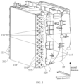
FIG. 1 is a structural schematic view of a heat exchanger installation structure according to an embodiment of the present application. -
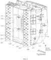
FIG. 2 is another structural schematic view of the heat exchanger installation structure inFIG. 1 . -
FIG. 3 is a front view of the heat exchanger installation structure inFIG. 2 . -
FIG. 4 is a cross-sectional view of the heat exchanger installation structure inFIG. 3 at A-A. -
FIG. 5 is a structural schematic view of the side plate inFIG. 2 . -
FIG. 6 is a front view of the side plate inFIG. 5 . -
FIG. 7 is a structural schematic view of a side plate of a heat exchanger installation structure according to another embodiment of the present application. -
FIG. 8 is a front view of the side plate inFIG. 7 . -
FIG. 9 is an installation schematic view of the side plate and the air duct inFIG. 2 . -
FIG. 10 is a structural schematic view of the air duct inFIG. 9 . -
FIG. 11 is another structural schematic view of the air duct inFIG. 9 . -
Reference number Name Reference number Name 10 air duct 211 heat exchange tube 11 air duct body 220 side plate 12 chute 221 first flange 111 third flange 222 second flange 112 fourth flange 223 second installation portion 113 first limiting portion 224 first pre-drilled hole area 114 first guide surface segment 225 second pre-drilled hole area 115 avoidance sink groove 226 pipeline installation hole 116 resisting-and-supporting portion 30 water receiving pan 117 second limiting portion 31 positioning hole 118 second guide surface segment 32 adjusting hole 20 heat exchanger 220 ' side plate 210 heat exchanger body - The realization of the purpose, functional features and advantages of the present application will be further described in conjunction with the embodiments and with reference to the accompanying drawings.
- The technical solutions in the embodiments according to the present application will be clearly and completely described below in conjunction with the accompanying drawings in the embodiments according to the present application, and it is clear that the described embodiments are only a part of the embodiments according to the present application, and not all of the embodiments. Based on the embodiments in the present application, all other embodiments obtained by those skilled in the art without making creative labor fall within the scope of the present application.
- It should be noted that if there are directional instructions (such as up, down, left, right, front, back or the like) involved in the embodiments of the present application, the directional indications are only used to explain the relative positional relationship, movement and so on between various components in a specific posture (as shown in the accompanying drawings). If the specific posture changes, the directional indication will also change accordingly.
- In addition, if there are descriptions involving "first", "second" or the like in the embodiments of the present application, the descriptions of "first", "second" or the like are only for descriptive purposes and cannot be understood as indicating or implying the relative importance or implicitly indicating the quantity of the technical features indicated. Therefore, features defined as "first" and "second" may explicitly or implicitly include at least one of these features. In addition, the meaning of "and/or" appearing in the entire text includes three parallel solutions, taking "A and/or B" as an example, it includes solution A, or solution B, or a solution that satisfies both A and B at the same time. In addition, the technical solutions of various embodiments can be combined with each other, but it is based on that those skilled in the art can realize. When the combination of technical solutions is contradictory or cannot be realized, it should be considered that such combination of technical solutions does not exist and is not within the protection scope claimed by the present application.
- The heat exchanger of the air conditioner is usually chosen to install together with the air duct, so that more gas after heat exchange in heat exchanger can flow into the air duct and flow through the air duct to the outside of the air conditioner, thereby achieving better heat exchange effect. The existing heat exchangers are usually installed with air ducts by using the side plates on both sides. However, parts of two side plate are usually affected by the layout structure of the heat exchange tube and the installation structure of the air duct, and are provided to be different structures. Since the contours and structures of the two side plates are very similar, workers can easily confuse the two side plates, thus leading to frequent misassembly problems.
- In view of this, the present application proposes a heat exchanger installation structure. Referring to
FIG. 1 to FIG. 4 , inFIG. 2 , the first direction refers to the direction from the right side of the heat exchanger in the figure to the left side of the heat exchanger in the figure, the second direction refers to the direction from the bottom side of the heat exchanger in the figure to the top side of the heat exchanger in the figure, and the third direction refers to the direction from the air duct to the heat exchanger. In an embodiment of the present application, the heat exchanger installation structure includes a heat exchanger 20. - The heat exchanger 20 includes a
heat exchanger body 210 and twoside plates 220 respectively provided at two opposite sides of theheat exchanger body 210, both the twoside plates 220 are provided with a side edge close to theair duct 10 of the air conditioner, side edge of the twoside plates 220 are both provided with afirst flange 221 toward the first direction, twofirst flanges 221 are connected with anair duct 10 of the air conditioner, and structures of the twoside plates 220 are identical. - In technical solutions of the present application, by providing the
first flanges 221 of the twoside plates 220 to face the same direction, that is, to fold in the first direction, so that the twoside plates 220 have sufficient conditions to be provided to have identical structure, that is, the twoside plates 220 are identical part. In this embodiment, the structures of twoside plates 220 are identical. In this way, after workers get the parts of theside plate 220, the workers can install the parts of theside plate 220 on the left side of the heat exchanger 20 or the right side of the heat exchanger 20 at will, that is, it can have the effect of preventing misassembly, and improving assembly efficiency. Secondly, it can simplify the material management of the parts of theside plate 220, thereby reducing the material management cost. Furthermore, since only one mold for part is developed, the mold development cost can be reduced, thereby reducing the overall development cost of the air conditioner. Certainly, the structures of the twoside plates 220 can also be provided to be different, that is, the twoside plates 220 are configured as two different parts. Regardless of whether the structures of the twoside plates 220 are identical, the foldedfirst flange 221 can play a role in strengthening the structural strength of theside plate 220 and use the position with higher structural strength to connect with theair duct 10, which can improve the reliability of the installation of the heat exchanger 20 andair duct 10. - Referring to
FIG. 4 and FIG. 5 , further, theside plate 220 is further provided with asecond flange 222 opposite to thefirst flange 221, and theheat exchanger body 210 is provided between thesecond flange 222 and thefirst flange 221. Thesecond flange 222 can also play a role in strengthening the structural strength of theside plate 220, thereby making the installation of theside plate 220 and theair duct 10 more reliable, and providing a more reliable installation effect for theheat exchanger body 210. - In an embodiment, the two
side plates 220 include a first side plate and a second side plate provided in sequence along the first direction, a heat exchange tube of the heat exchanger includes a main tube portion and an elbow, the main tube portion is provided with a welded end passing through the first side plate, and the elbow is welded to the welded end. Without loss of generality, material of theheat exchange tube 211 is usually made of copper material or aluminum material, the corresponding heat exchanger is called copper tube heat exchanger or aluminum tube heat exchanger. The side plate of the aluminum tube heat exchanger is usually made of aluminum. In this way, folding both thefirst flange 221 and thesecond flange 222 along the direction away from the welded end of theheat exchange tube 211, for the aluminum tube heat exchanger, when performing welding operations to the welded end of the heat exchange tube and the elbow of the heat exchange tube, it can prevent thefirst flange 221 made of aluminum and thesecond flange 222 made of aluminum from being melted and damaged by high-temperature welding guns or spatter. It can be understood that the heat exchanger installation structure is also applicable to the copper tube heat exchanger. That is, this side plate can be used not only for air conditioner products of copper tube heat exchanger, but also for air conditioner products of aluminum tube heat exchanger, thereby improving the adaptability of theside plate 220, and then reducing the development cost of the air conditioner. - Referring to
FIG. 1 ,FIG. 2 andFIG. 5 , in an embodiment, thesecond flange 222 is provided with asecond installation portion 223, and thesecond installation portion 223 is connected with awater receiving pan 30. In this way, adding another installation point to theheat exchanger body 210 by thesecond installation portion 223, and thesecond installation portion 223 is installed with thewater receiving pan 30, thus, it can further improve the reliability and stability of the installation of theheat exchanger body 210. - Referring to
FIG. 1 ,FIG. 2 andFIG. 4 , in an embodiment, thesecond installation part 223 is a threaded bottom hole, and the heat exchanger installation structure further includes awater receiving pan 30; thewater receiving pan 30 is respectively provided with apositioning hole 31 and an adjustinghole 32 corresponding to two threaded bottom holes, and the adjustinghole 32 and thepositioning hole 31 are provided at intervals along the first direction. It should be noted that the size of thepositioning hole 31 is adapted to the threaded bottom hole, and the size of the adjustinghole 32 in the first direction is larger than the threaded bottom hole, so that when theside plate 220 and thewater receiving pan 30 adapt the screw lock attachment, the adjustinghole 32 can effectively offset the influence of the dimensional manufacturing tolerance of the heat exchanger 20, the assembly tolerance of the heat exchanger 20 and the dimensional manufacturing tolerance of thewater receiving pan 30, thus making it easier for workers to install, thereby improving assembly efficiency. Secondly, utilizing the adjustinghole 32, the water receiving pan30 can further be adapted to the heat exchanger 20 of different models, it is conducive to the platform design of thewater receiving pan 30, thereby reducing the product development cost of the air conditioner. Furthermore, adapting the fixation method of screw lock attachment can simplify the installation structure of thesecond installation portion 223 and thewater receiving pan 30, thereby reducing the manufacturing cost of the air conditioner, and the installation operation of the screw connection is simple and convenient, thereby improving the assembly efficiency. Specifically, thepositioning hole 31 may be a round hole or a regular polygon hole provided to be adapt to the threaded bottom hole, the adjustinghole 32 may be provided to be a rectangular hole, a waist-shaped hole, or an elliptical hole, and the long axis of the adjustinghole 32 extends along the first direction. However, the present design is not limited to this. In other embodiments, the second installation portion further may be a snap-in protrusion provided on a side of the second flange away from the heat exchanger body, the water receiving pan is provided with a snap-in hole corresponding to the snap-in protrusion, and the snap-in protrusion is snapped in the snap-in hole. - Referring to
FIG. 1 ,FIG. 3 andFIG. 5 , in an embodiment, a plurality of threaded bottom holes are provided, and the plurality of threaded bottom holes are provided at intervals along the second direction. In this way, at least one threaded bottom hole is provided as a reserved installation hole, so that the parts of theside plates 220 with identical structure can be adapted to theheat exchanger body 210 of different models orwater receiving pan 30 of different models, thereby facilitating the platform design of theside plate 220, and then reducing the overall development cost of the air conditioner. - Referring to
FIG. 5 andFIG. 6 ,FIG. 5 is a structural schematic view of theside plate 220 of this embodiment, andFIG. 6 is a front view of theside plate 220 inFIG. 5 . Theside plate 220 of this embodiment is only provided with apipeline installation hole 226 in the firstpre-drilled hole area 224, and can be adapted and installed with theheat exchanger body 210 of the first model. In this embodiment, in an embodiment, theside plate 220 is provided with a firstpre-drilled hole area 224 and a secondpre-drilled hole area 225, the firstpre-drilled hole area 224 is configured for an installation of theheat exchanger body 210 of a first model, and the firstpre-drilled hole area 224 and the secondpre-drilled hole area 225 are jointly configured for an installation of theheat exchanger body 210 of a second model. It should be noted that, referring toFIG. 2 , theheat exchanger body 210 usually includes a plurality ofheat exchange tubes 211. Assuming that theheat exchanger body 210 of the first model is provided with a smaller number ofheat exchange tube 211, and the heat exchanger body of the second model is provided with a larger number of heat exchange tubes. Then referring toFIG. 7 andFIG. 8 ,FIG. 7 is a structural schematic view of the side plate 220' of another embodiment, andFIG. 8 is a front view of the side plate 220' inFIG. 7 . The side plate 220' of another embodiment is provided with pipeline installation holes 226 in the firstpre-drilled hole area 224 and the secondpre-drilled hole area 225, and can be adapted and installed with the heat exchanger body of the second model. It can be understood that both the firstpre-drilled hole area 224 and the secondpre-drilled hole area 225 can be provided with a plurality of pipeline installation holes 226 for theheat exchange tube 211 to be passed through and installed, and thepipeline installation hole 226 corresponding to theheat exchange tube 211 of the second model product is at least partially identical structure and same installation location as thepipeline installation hole 226 corresponding to theheat exchange tube 211 of the first model product. It can be understood that if theside plate 220 is only provided with thepipeline installation hole 226 in the firstpre-drilled hole area 224, then the parts of theside plate 220 of the first model can only be adapted to install theheat exchanger body 210 of the first model; if theside plate 220 is provided with pipeline installation holes 226 in both the firstpre-drilled hole area 224 and the secondpre-drilled hole area 225, then the parts of theside plate 220 of the second model can be adapted to install theheat exchanger body 210 of the first model, and can also be adapted to install theheat exchanger body 210 of the second model. It can be understood that if directly adapting the parts of theside plate 220 of the second model to install with theheat exchanger body 210 of the first model, then thepipeline installation hole 226 on the secondpre-drilled hole area 225 is in an idle state, which will arouse users' suspicion, for example, users may think that the manufacturer secretly lowers the configuration, which will lead to user complaints. Therefore, in order to avoid causing user complaints, aiming that heat exchangers 20 of different models need to use the parts of theside plate 220 of different models, under this premise, thepipeline installation hole 226 on the firstpre-drilled hole area 224 is provided to be shared by the heat exchangers of different models, thereby, the forming molds of theside plate 220 and thepipeline installation hole 226 thereon can be at least partially shared, and then the mold development costs can be reduced, and the overall development cost of air conditioners can be reduced. - Referring to
FIG. 2 ,FIG. 5 andFIG. 6 , further, theheat exchanger body 210 includes a plurality ofheat exchange tubes 211, and the firstpre-drilled hole area 224 is provided with a plurality of pipeline row holes at intervals along a width direction of theside plate 220; the pipeline row holes include a plurality of pipeline installation holes 226 provided at intervals along a length direction of theside plate 220, and the pipeline installation holes 226 are configured for theheat exchange tubes 211 to be passed through and installed. It should be noted that "a plurality of' refers to two or more. In this way, the plurality of pipeline installation holes 226 on the firstpre-drilled hole area 224 are arranged in an orderly manner, which not only helps to improve the heat exchange efficiency of theheat exchanger body 210, but also simplifies the mold structure of theside plate 220, thereby reducing the mold development cost. - Referring to
FIG. 7 andFIG. 8 , in this embodiment, further, the secondpre-drilled hole area 225 is provided with at least one pipeline row hole, the pipeline row hole includes a plurality of pipeline installation holes 226 provided at intervals along the length direction of theside plate 220. In this way, the plurality of pipeline installation holes 226 on the secondpre-drilled hole area 225 are arranged in an orderly manner, which not only helps to improve the heat exchange efficiency of theheat exchanger body 210, but also simplifies the mold structure of theside plate 220, thereby reducing the mold development cost. - In an embodiment, the
pipeline installation hole 226 on theside plate 220 is provided to be formed by punching adopting a stamping forming process. In this way, thepipeline installation hole 226 on the firstpre-drilled hole area 224 and thepipeline installation hole 226 on the secondpre-drilled hole area 225 can be divided into two punching processes for forming, thepipeline installation hole 226 on the secondpre-drilled hole area 225 is selectively formed according to product requirements, so that the parts of theside plate 220 with different structures can share a part of the forming molds, thus reducing the mold development cost, thereby reducing the overall development cost of the air conditioner. Specifically, theside plate 220 can use a stamping drawing process or extrusion molding process to form thefirst flange 221 and thesecond flange 222, and then theside plate 220 is sent to the first punching process, using the first punching mold to punch out thepipeline installation hole 226 on the firstpre-drilled hole area 224, and then directly obtaining the parts of theside plate 220 of the first model that can be adapted to install theheat exchanger body 210 of the first model. If you want to get the parts of the side plate 220' of the second model that can be adapted to install the second heat exchanger body of the second model, you can continue to send the parts of theside plate 220 of the first model to the second punching process, and use the second punching mold to punch out thepipeline installation hole 226 on the secondpre-drilled hole area 225. In this way, theside plate 220 of the first model and the side plate 220' of the second model at least share a drawing forming mold or an extrusion forming mold and a first punching mold, thus achieving the purpose of reducing mold development costs, thereby reducing the overall development cost of air conditioners. However, the present design is not limited to this. In other embodiments, the side plate can further be provided by adopting injection forming, the female mold of the injection mold of the parts of two side plate of the first model and the second model can achieve full sharing, while the male mold of the injection mold can achieve partial structure sharing. - Referring to
FIG. 6 andFIG. 8 , in an embodiment, the firstpre-drilled hole area 224 and the secondpre-drilled hole area 225 are provided in sequence in a direction from theside plate 220 toward theair duct 10. Without loss of generality, theair duct 10 is usually provided inside the air conditioner, so the side of theheat exchanger body 210 close to theair duct 10 is hidden in the air conditioner, while the side of theheat exchanger body 210 away from theair duct 10 can be seen by the user. By providing the secondpre-drilled hole area 225 at a position close to theair duct 10, the secondpre-drilled hole area 225 can be hidden, that is, for air conditioner products of different models, the appearance of the heat exchanger20 when viewed from the outside is the same. For example, as shown inFIG. 4 , the side of theheat exchanger body 210 of the first model away from theair duct 10 is nearly flush with the end surface of thesecond flange 222, and the side of the heat exchanger body of the second model away from the air duct can also achieve this state. However, the present design is not limited to this. In other embodiments, it further can be that the second pre-drilled hole area is provided in the first pre-drilled hole area. - Referring to
FIG. 9 to FIG. 11 , in an embodiment, the heat exchanger installation structure further includes anair duct 10, theair duct 10 includes anair duct body 11 and achute 12 provided at theair duct body 11, twochutes 12 are provided corresponding to the twofirst flanges 221; thefirst flange 221 is slidingly inserted into thechute 12 along a second direction, and the second direction is configured to intersect with the first direction. It should be noted that the second direction refers to the length direction of theside plate 220, and the first direction is the thickness direction of theside plate 220. In this way, the installation structure of the heat exchanger 20 and theair duct 10 can be simplified, thereby reducing the manufacturing cost. Moreover, the installation that thefirst flange 221 slidingly inserted into thechute 12 is easy to operate, thereby improving the assembly efficiency. However, the present design is not limited to this. In other embodiments, it further can be that the heat exchanger installation structure may further include an air duct, the air duct includes an air duct body and a snap-in protrusion provided at the side edge of the air duct body, the first flange is provided with a snap-in hole corresponding to the snap-in protrusion, and the snap-in protrusion is snapped in the snap-in hole. - Referring to
FIG. 10 andFIG. 11 , in an embodiment, the side edge of theair duct body 11 is provided with athird flange 111 extending along the first direction, thethird flange 111 is provided with afourth flange 112 extending along the direction toward theheat exchanger body 210, and thefourth flange 112 is provided with a first limitingportion 113 protruding along a direction away from the first direction. Thethird flange 111, thefourth flange 112 and the first limitingportion 113 jointly define thechute 12. In this way, using thethird flange 111 and thefourth flange 112 can not only strengthen the structural strength of the side edge of theair duct body 11, it further can cooperate with the first limitingportion 113 to limit thefirst flange 221 in thechute 12. The molding structure of thechute 12 is not only simple in structure, which is beneficial to reducing the manufacturing cost of theair duct 10, but also has good structural strength, thereby improving the stability and reliability of installation of theair duct 10 and the heat exchanger 20. However, the design is not limited to this. In other embodiments, it further can be that the end surface of the side edge facing the heat exchanger body of the air duct body may be provided with a groove. The groove is provided with a first end and a second end distributed in sequence in the second direction, and the edge of the mouth of the groove of the second end is provided with a limiting convex portion protruding toward the center of the mouth of the groove, and the limiting convex portion is abutted against a side of the first flange away from the air duct body. - Referring to
FIG. 10 , in an embodiment, the first limitingportion 113 is provided with a first side edge and a second side edge distributed in sequence in the second direction, and the side surface of the first limitingportion 113 facing thethird flange 111 includes a firstguide surface segment 114 close to the first side edge. In the second direction, the firstguide surface segment 114 extends obliquely in a direction close to thefourth flange 112. In this way, the firstguide surface segment 114 can play a good guiding role, thereby making it convenient for workers to operate thefirst flange 221 to slide and insert into thechute 12 along the second direction. - Referring to
FIG. 9 andFIG. 10 , in an embodiment, thethird flange 111 is provided with anavoidance sink groove 115 corresponding to the first limitingportion 113. Without loss of generality, theair duct 10 is usually manufactured adopting an injection molding process due to its relatively complex structure and relatively high structural strength requirements. It can be understood that in the direction from theside plate 220 toward theair duct 10, the smaller the width of thechute 12 is, the more conducive it is to limit the displacement of theside plate 220 in this direction, therefore, the amount of shaking of theside plate 220 in this direction can be reduced, making the installation of theside plate 220 and theair duct 10 more stable and reliable. Since the thickness of thefirst flange 221 in this direction is usually relatively small, which can meet the installation strength requirements, the width of thechute 12 is provided to be relatively small concomitantly. However, if the distance between thethird flange 111 and the first limitingportion 113 is too small, the mold structure corresponding thereto will be relatively thin, resulting in the mold structure being prone to problems and having a short service life. Therefore, by partially sinking the area of thethird flange 111 corresponding to the first limitingportion 113, that is, providing a structure of theavoidance sink groove 115, the mold structure corresponding to this place can achieve a thickening effect, thereby reducing the probability of mold errors, and increasing the service life of the mold. - In an embodiment, the
third flange 111 is recessed with a stepped portion corresponding to the first limitingportion 113, and theavoidance sink groove 115 is provided on the bottom wall of the stepped portion. In this way, by providing the stepped portion, it can not only strengthen the mold structure corresponding to theavoidance sink groove 115, but also further strengthen the structural strength of thethird flange 111 itself, thereby improving the structural strength of thechute 12, and then improving the stability and reliability of the installation of the heat exchanger 20 and theair duct 10. - Referring to
FIG. 9 andFIG. 10 , in an embodiment, a resisting-and-supportingportion 116 protrudes from the middle portion of the groove bottom of theavoidance sink groove 115 toward the first limitingportion 113, and the side of thefirst flange 221 facing theavoidance sink groove 115 is abutted against the resisting-and-supportingportion 116. In this way, on the premise of improving the structural strength of the mold, the resisting-and-supportingportion 116 and the first limitingportion 113 are configured to jointly play a limiting role in thefirst flange 221, thus improving the limiting effect of thechute 12 on thefirst flange 221, thereby reducing the probability of theside plate 220 loosening and shaking after installation. - Referring to
FIG. 10 andFIG. 11 , in an embodiment, the peripheral surface of the resisting-and-supportingportion 116 is provided in an arc surface. In this way, the resisting-and-supportingportion 116 can play a good guiding role, thereby facilitating the worker to operate thefirst flange 221 to slide across theavoidance sink groove 115 along the second direction and insert it deeper. However, the present design is not limited to this. In other embodiments, it further can be that the resisting-and-supporting portion is provided with a fifth side edge and a sixth side edges distributed in sequence in the second direction, and the side surface of the resisting-and-supporting portion facing the first limiting portion includes a third guide surface segment close to the fifth side edge; in the second direction, the third guide surface segment extends obliquely in a direction close to the first limiting portion. - In an embodiment, the resisting-and-supporting
portion 116 is provided to be protruded from the bottom surface of the groove of thethird flange 111. In this way, the resisting-and-supportingportion 116 and the first limitingportion 113 can better limit thefirst flange 221 of theside plate 220 in thechute 12, thus further reducing the probability ofside plate 220 loosening and shaking after installation, thereby improving the stability and reliability of the installation of heat exchanger 20 andair duct 10. - Referring to
FIG. 10 andFIG. 11 , in an embodiment, a plurality of first limitingportions 113 are provided, and the plurality of first limitingportions 113 are provided at intervals along the second direction. In this way, thefirst flange 221 can be better limited in thechute 12, thus reducing the probability ofside plate 220 loosening and shaking after installation, thereby improving the stability and reliability of the installation of heat exchanger 20 andair duct 10. - Referring to
FIG. 9 ,FIG. 10 andFIG. 11 , in an embodiment, the twochute 12 include afirst chute 12 and asecond chute 12 provided in sequence along the first direction, thethird flange 111 on thefirst chute 12 protrudes toward theheat exchanger body 210 with a second limitingportion 117, and the side of the second limitingportion 117 facing thefirst chute 12 is abutted against theside plate 220. In this way, the second limitingportion 117 is used to abut against theside plate 220, which can prevent theside plate 220 from slipping out of thefirst chute 12 along a direction away from the first direction, thereby improving the reliability and stability of the installation of heat exchanger 20 andair duct 10. It can be understood that since bothside plates 220 are fixed relative to theheat exchanger body 210, and only one of theside plates 220 is limited so that it will not slip along a direction away from the first direction. Thus, it can ensure that theother side plate 220, theheat exchanger body 210, and theair duct 10 maintain a good connection relationship. In this way, the installation structure of theair duct 10 can be simplified, thereby reducing the manufacturing cost of theair duct 10. However, the present design is not limited to this. In other embodiments, it further can be that both the third flange on the first chute and the third flange on the second chute may be provided with a second limiting portion, and the side of the second limiting portion facing the fourth flange is abutted against the side plate. - Referring to
FIG. 10 andFIG. 11 , in an embodiment, the second limitingportion 117 is provided with a third side edge and a fourth side edge distributed in sequence in the second direction, and the side surface of the second limitingportion 117 facing thefourth flange 112 includes a secondguide surface segment 118 close to the first side edge; in the second direction, the secondguide surface segment 118 extends obliquely in a direction close to thefourth flange 112. In this way, the secondguide surface segment 118 can play a good guiding role, thereby making it convenient for workers to operate thefirst flange 221 to slide and insert into thechute 12 along the second direction. - Referring to
FIG. 10 andFIG. 11 , in an embodiment, the second limitingportion 117 and the first limitingportion 113 are provided in a staggered arrangement in the second direction. In this way, the forming mold structure of theair duct 10 can be simplified, thereby reducing the mold development cost of theair duct 10. - Referring to
FIG. 10 andFIG. 11 , in an embodiment, a plurality of second limitingportions 117 are provided, and the plurality of second limitingportions 117 are provided at intervals along the second direction. Thefirst flange 221 can be better limited in thechute 12, thus reducing the probability that theside plate 220 will accidentally slip out of thechute 12 after installation, thereby improving the stability of the installation of the heat exchanger 20 and theair duct 10. - The present application further proposes an air conditioner including the aforementioned heat exchanger installation structure. The specific structure of the heat exchanger installation structure refers to the above embodiment. Since this air conditioner adopts all the technical solutions of all the above-mentioned embodiments, it has at least all the beneficial effects brought by the technical solutions of the above-mentioned embodiments, which will not be described again here.
- The above are only some embodiments of the present application, and are not intended to limit the scope of the present application. Under the concept of the present application, any equivalent structure transformation made by using the description and accompanying drawings of the present application, or directly or indirectly applied in other related technical fields, is included within the scope of the present application.
Claims (10)
- A heat exchanger installation structure, applied to an air conditioner, comprising:a heat exchanger comprising a heat exchanger body and two side plates respectively provided at two opposite sides of the heat exchanger body,wherein same side edges of the two side plates are each folded toward a first direction to form a first flange, wherein the two first flanges are configured to be connected with an air duct of the air conditioner, and structures of the two side plates are identical.
- The heat exchanger installation structure according to claim 1, wherein each of the side plates is further provided with a second flange opposite the first flange, and the heat exchanger body is provided between the second flanges and the first flanges.
- The heat exchanger installation structure according to claim 2, wherein each of the second flanges is provided with a second installation portion, and the second installation portions are configured to be connected with a water receiving pan of the air conditioner.
- The heat exchanger installation structure according to claim 3, wherein each of the second flanges is provided with a plurality of second installation portions, and the plurality of the second installation portions are provided at intervals along a length direction of the side plate.
- The heat exchanger installation structure according to claim 3, wherein each of the second installation portions is provided in a form of a threaded bottom hole, and the heat exchanger installation structure further comprises the water receiving pan; the water receiving pan is provided with a positioning hole and an adjusting hole corresponding to the two threaded bottom holes respectively, and the adjusting hole and the positioning hole are provided at an interval along the first direction.
- The heat exchanger installation structure according to claim 1, wherein each of the side plates is provided with a first pre-drilled hole area and a second pre-drilled hole area, the first pre-drilled hole area is configured for installation of the heat exchanger body of a first model, and the first pre-drilled hole area and the second pre-drilled hole area are jointly configured for installation of the heat exchanger body of a second model.
- The heat exchanger installation structure according to claim 6, wherein the first pre-drilled hole area and the second pre-drilled hole area are provided in sequence in a direction from the side plate to the air duct.
- The heat exchanger installation structure according to claim 6, wherein the heat exchanger body comprises a plurality of heat exchange tubes, and the first pre-drilled hole area is provided with a plurality of pipeline row holes at intervals along a width direction of the side plate; the pipeline row holes comprise a plurality of pipeline installation holes provided at intervals along a length direction of the side plate, and the pipeline installation holes are configured for the heat exchange tubes to be passed through and installed.
- The heat exchanger installation structure according to claim 1, further comprising:the air duct comprising an air duct body and a chute provided at the air duct body,wherein two chutes are provided corresponding to the two first flanges; each of the first flanges is slidingly inserted into a corresponding chute along a second direction, and the second direction is configured to intersect with the first direction; and/orthe two side plates comprise a first side plate and a second side plate provided in sequence along the first direction, a heat exchange tube of the heat exchanger comprises a main tube portion and an elbow, the main tube portion is provided with a weld end passing through the first side plate, and the elbow is welded to the weld end.
- An air conditioner, comprising the heat exchanger installation structure according to any one of claims 1 to 9.
Applications Claiming Priority (3)
| Application Number | Priority Date | Filing Date | Title |
|---|---|---|---|
| CN202111454989.XA CN116202136B (en) | 2021-11-30 | 2021-11-30 | Heat exchanger installation structure and air conditioner |
| CN202123024505.6U CN216308007U (en) | 2021-11-30 | 2021-11-30 | Heat exchanger mounting structure and air conditioner |
| PCT/CN2022/095258 WO2023097997A1 (en) | 2021-11-30 | 2022-05-26 | Heat exchanger mounting structure and air conditioner |
Publications (3)
| Publication Number | Publication Date |
|---|---|
| EP4414624A1 true EP4414624A1 (en) | 2024-08-14 |
| EP4414624A4 EP4414624A4 (en) | 2025-02-19 |
| EP4414624B1 EP4414624B1 (en) | 2026-04-29 |
Family
ID=86611453
Family Applications (1)
| Application Number | Title | Priority Date | Filing Date |
|---|---|---|---|
| EP22899817.5A Active EP4414624B1 (en) | 2021-11-30 | 2022-05-26 | Heat exchanger mounting structure and air conditioner |
Country Status (3)
| Country | Link |
|---|---|
| US (1) | US20250035335A1 (en) |
| EP (1) | EP4414624B1 (en) |
| WO (1) | WO2023097997A1 (en) |
Cited By (1)
| Publication number | Priority date | Publication date | Assignee | Title |
|---|---|---|---|---|
| EP4481312A4 (en) * | 2022-03-18 | 2025-06-25 | Zhejiang Dunan Artificial Environment Co., Ltd. | MOUNTING STRUCTURE AND INSERT PLATE HEAT EXCHANGER SO |
Family Cites Families (21)
| Publication number | Priority date | Publication date | Assignee | Title |
|---|---|---|---|---|
| JPH05164348A (en) * | 1991-12-16 | 1993-06-29 | Hitachi Ltd | Air conditioner |
| EP0896138B1 (en) * | 1997-08-08 | 2003-04-23 | Kobelco Construction Machinery Co., Ltd. | Cooling apparatus for construction machine |
| US6179050B1 (en) * | 1999-09-29 | 2001-01-30 | Valeo Thermique Moteur | Heat exchangers |
| KR100988572B1 (en) * | 2003-08-14 | 2010-10-18 | 삼성전자주식회사 | Outdoor unit of air conditioner |
| US20090120610A1 (en) * | 2007-11-08 | 2009-05-14 | Delphi Technologies, Inc. | Sealing system for a heat exchanger assembly |
| JP2009180443A (en) * | 2008-01-31 | 2009-08-13 | Sharp Corp | Casing structure of outdoor unit of air conditioner |
| JP4991904B2 (en) * | 2010-04-26 | 2012-08-08 | シャープ株式会社 | Heat exchanger |
| JP2013072607A (en) * | 2011-09-28 | 2013-04-22 | Keihin Thermal Technology Corp | Method of manufacturing heat exchanger |
| US9958217B1 (en) * | 2013-06-19 | 2018-05-01 | Nooter/Eriksen, Inc. | Baffle system and method for a heat exchanger located within a casing of a heat recovery steam generator |
| CN203857861U (en) * | 2014-04-18 | 2014-10-01 | Tcl空调器(中山)有限公司 | Heat exchanger end plate of window type air conditioner, heat exchanger and window type air conditioner |
| US11137212B2 (en) * | 2016-06-23 | 2021-10-05 | Hanon Systems | Bypass seal for plate heater matrix |
| CN206095025U (en) * | 2016-10-08 | 2017-04-12 | 珠海格力电器股份有限公司 | Side plate of heat exchanger for air conditioner, heat exchanger for air conditioner and air conditioner |
| CN106403696A (en) * | 2016-10-08 | 2017-02-15 | 珠海格力电器股份有限公司 | Side plate of heat exchanger for air conditioner, heat exchanger for air conditioner and air conditioner |
| CN106568186A (en) * | 2016-10-19 | 2017-04-19 | 珠海格力电器股份有限公司 | A side plate fixing structure and an integral window machine |
| CN206926479U (en) * | 2017-05-11 | 2018-01-26 | 豫新汽车空调股份有限公司 | A kind of side board structure of warm wind core of vehicle air conditioner |
| CN208952386U (en) * | 2018-10-22 | 2019-06-07 | 宁波奥克斯电气股份有限公司 | Evaporator side plate and air conditioner thereof |
| FR3090843B1 (en) * | 2018-12-19 | 2020-11-27 | Valeo Systemes Thermiques | Motor vehicle heat exchanger sealing device |
| CN213990078U (en) * | 2020-10-29 | 2021-08-17 | 南通大通电气有限公司 | Square tube sealing connector formed by two identical connecting sheets |
| CN214502161U (en) * | 2021-01-18 | 2021-10-26 | 海信(广东)空调有限公司 | Heat Exchangers and Window Air Conditioners |
| CN216308007U (en) * | 2021-11-30 | 2022-04-15 | 美的集团武汉制冷设备有限公司 | Heat exchanger mounting structure and air conditioner |
| CN216244829U (en) * | 2021-11-30 | 2022-04-08 | 广东美的制冷设备有限公司 | Air duct structure and air conditioner |
-
2022
- 2022-05-26 WO PCT/CN2022/095258 patent/WO2023097997A1/en not_active Ceased
- 2022-05-26 EP EP22899817.5A patent/EP4414624B1/en active Active
- 2022-05-26 US US18/713,983 patent/US20250035335A1/en active Pending
Cited By (1)
| Publication number | Priority date | Publication date | Assignee | Title |
|---|---|---|---|---|
| EP4481312A4 (en) * | 2022-03-18 | 2025-06-25 | Zhejiang Dunan Artificial Environment Co., Ltd. | MOUNTING STRUCTURE AND INSERT PLATE HEAT EXCHANGER SO |
Also Published As
| Publication number | Publication date |
|---|---|
| US20250035335A1 (en) | 2025-01-30 |
| WO2023097997A1 (en) | 2023-06-08 |
| EP4414624A4 (en) | 2025-02-19 |
| EP4414624B1 (en) | 2026-04-29 |
Similar Documents
| Publication | Publication Date | Title |
|---|---|---|
| CN107560484B (en) | Connecting piece and microchannel heat exchanger | |
| CN216308007U (en) | Heat exchanger mounting structure and air conditioner | |
| US11874066B2 (en) | Micro-channel heat exchanger | |
| CN109595951B (en) | Heat exchange device | |
| EP4414624A1 (en) | Heat exchanger mounting structure and air conditioner | |
| CN114440033B (en) | Automobile and liquid cooling battery waterway system and water pipe quick connector thereof | |
| KR101819488B1 (en) | Cooling module and method of assembly | |
| CN115479483A (en) | Heat exchanger | |
| CN216244829U (en) | Air duct structure and air conditioner | |
| CN206247711U (en) | Multi-bended heat exchanger and air-conditioner | |
| CN116202136B (en) | Heat exchanger installation structure and air conditioner | |
| CN210426171U (en) | Flat pipe and heat exchanger | |
| CN106642824B (en) | Multi-fold heat exchanger and air conditioner | |
| CN209042713U (en) | An integrated panel, outdoor unit and air conditioner matching long and short expansion and high condenser | |
| CN208124711U (en) | A kind of air return structure of wind cooling refrigerator | |
| US20250003690A1 (en) | Heat exchange assembly and heat exchange system | |
| CN222142220U (en) | Engine water outlet pipe connecting mechanism | |
| CN207365782U (en) | A kind of flat pipes of heat exchanger | |
| CN207635581U (en) | Panel assembly and the apparatus of air conditioning | |
| CN207045099U (en) | A kind of interface arrangment of automobile primary defroster nozzle | |
| CN220187486U (en) | Anti-seismic fin tube type heat exchanger | |
| CN212362958U (en) | Micro-channel connecting piece and heat exchanger with same | |
| CN207065842U (en) | Wall-hanging air conditioner motor cover and air conditioner | |
| CN218627937U (en) | Service side multi-process graphite block structure | |
| CN224202252U (en) | A heat exchanger |
Legal Events
| Date | Code | Title | Description |
|---|---|---|---|
| STAA | Information on the status of an ep patent application or granted ep patent |
Free format text: STATUS: THE INTERNATIONAL PUBLICATION HAS BEEN MADE |
|
| PUAI | Public reference made under article 153(3) epc to a published international application that has entered the european phase |
Free format text: ORIGINAL CODE: 0009012 |
|
| STAA | Information on the status of an ep patent application or granted ep patent |
Free format text: STATUS: REQUEST FOR EXAMINATION WAS MADE |
|
| 17P | Request for examination filed |
Effective date: 20240507 |
|
| AK | Designated contracting states |
Kind code of ref document: A1 Designated state(s): AL AT BE BG CH CY CZ DE DK EE ES FI FR GB GR HR HU IE IS IT LI LT LU LV MC MK MT NL NO PL PT RO RS SE SI SK SM TR |
|
| A4 | Supplementary search report drawn up and despatched |
Effective date: 20250117 |
|
| RIC1 | Information provided on ipc code assigned before grant |
Ipc: F28F 9/02 20060101ALI20250113BHEP Ipc: F24F 13/22 20060101ALI20250113BHEP Ipc: F24F 1/18 20110101ALI20250113BHEP Ipc: F24F 13/30 20060101AFI20250113BHEP |
|
| DAV | Request for validation of the european patent (deleted) | ||
| DAX | Request for extension of the european patent (deleted) | ||
| STAA | Information on the status of an ep patent application or granted ep patent |
Free format text: STATUS: EXAMINATION IS IN PROGRESS |
|
| 17Q | First examination report despatched |
Effective date: 20251112 |
|
| GRAP | Despatch of communication of intention to grant a patent |
Free format text: ORIGINAL CODE: EPIDOSNIGR1 |
|
| STAA | Information on the status of an ep patent application or granted ep patent |
Free format text: STATUS: GRANT OF PATENT IS INTENDED |
|
| INTG | Intention to grant announced |
Effective date: 20260209 |
|
| GRAS | Grant fee paid |
Free format text: ORIGINAL CODE: EPIDOSNIGR3 |
|
| GRAA | (expected) grant |
Free format text: ORIGINAL CODE: 0009210 |
|
| STAA | Information on the status of an ep patent application or granted ep patent |
Free format text: STATUS: THE PATENT HAS BEEN GRANTED |
|
| AK | Designated contracting states |
Kind code of ref document: B1 Designated state(s): AL AT BE BG CH CY CZ DE DK EE ES FI FR GB GR HR HU IE IS IT LI LT LU LV MC MK MT NL NO PL PT RO RS SE SI SK SM TR |
|
| REG | Reference to a national code |
Ref country code: CH Ref legal event code: F10 Free format text: ST27 STATUS EVENT CODE: U-0-0-F10-F00 (AS PROVIDED BY THE NATIONAL OFFICE) Effective date: 20260429 |