EP4414623A1 - Mask assembly for air conditioner indoor unit, air conditioner indoor unit and air conditioner - Google Patents
Mask assembly for air conditioner indoor unit, air conditioner indoor unit and air conditioner Download PDFInfo
- Publication number
- EP4414623A1 EP4414623A1 EP22884955.0A EP22884955A EP4414623A1 EP 4414623 A1 EP4414623 A1 EP 4414623A1 EP 22884955 A EP22884955 A EP 22884955A EP 4414623 A1 EP4414623 A1 EP 4414623A1
- Authority
- EP
- European Patent Office
- Prior art keywords
- cover
- air deflector
- air conditioner
- support
- indoor unit
- Prior art date
- Legal status (The legal status is an assumption and is not a legal conclusion. Google has not performed a legal analysis and makes no representation as to the accuracy of the status listed.)
- Pending
Links
Images


Classifications
-
- F—MECHANICAL ENGINEERING; LIGHTING; HEATING; WEAPONS; BLASTING
- F24—HEATING; RANGES; VENTILATING
- F24F—AIR-CONDITIONING; AIR-HUMIDIFICATION; VENTILATION; USE OF AIR CURRENTS FOR SCREENING
- F24F13/00—Details common to, or for air-conditioning, air-humidification, ventilation or use of air currents for screening
- F24F13/08—Air-flow control members, e.g. louvres, grilles, flaps or guide plates
- F24F13/10—Air-flow control members, e.g. louvres, grilles, flaps or guide plates movable, e.g. dampers
- F24F13/14—Air-flow control members, e.g. louvres, grilles, flaps or guide plates movable, e.g. dampers built up of tilting members, e.g. louvre
-
- F—MECHANICAL ENGINEERING; LIGHTING; HEATING; WEAPONS; BLASTING
- F24—HEATING; RANGES; VENTILATING
- F24F—AIR-CONDITIONING; AIR-HUMIDIFICATION; VENTILATION; USE OF AIR CURRENTS FOR SCREENING
- F24F1/00—Room units for air-conditioning, e.g. separate or self-contained units or units receiving primary air from a central station
- F24F1/0007—Indoor units, e.g. fan coil units
- F24F1/0011—Indoor units, e.g. fan coil units characterised by air outlets
-
- F—MECHANICAL ENGINEERING; LIGHTING; HEATING; WEAPONS; BLASTING
- F24—HEATING; RANGES; VENTILATING
- F24F—AIR-CONDITIONING; AIR-HUMIDIFICATION; VENTILATION; USE OF AIR CURRENTS FOR SCREENING
- F24F13/00—Details common to, or for air-conditioning, air-humidification, ventilation or use of air currents for screening
- F24F13/20—Casings or covers
-
- F—MECHANICAL ENGINEERING; LIGHTING; HEATING; WEAPONS; BLASTING
- F24—HEATING; RANGES; VENTILATING
- F24F—AIR-CONDITIONING; AIR-HUMIDIFICATION; VENTILATION; USE OF AIR CURRENTS FOR SCREENING
- F24F1/00—Room units for air-conditioning, e.g. separate or self-contained units or units receiving primary air from a central station
- F24F1/0007—Indoor units, e.g. fan coil units
- F24F1/0043—Indoor units, e.g. fan coil units characterised by mounting arrangements
- F24F1/0047—Indoor units, e.g. fan coil units characterised by mounting arrangements mounted in the ceiling or at the ceiling
Definitions
- the present application relates to the field of household electrical appliances, and more particularly, to a cover assembly of an air conditioner indoor unit, an air conditioner indoor unit, and an air conditioner.
- an air conditioner indoor unit has the following disadvantages. Firstly, a gap between a lower edge of a small air deflector and a lower panel is large due to air guide movement requirements of the small air deflector, and an appearance of the whole air conditioner is inaesthetic due to the gap after the small air deflector is closed. Secondly, a current scheme cannot realize a function of avoiding a direct blowing of cold air. Thirdly, the current scheme cannot realize an expansion of a function of airstill. Fourthly, easy-to-disassemble and washable air conditioner schemes of competitive air conditioner must first remove a large air deflector and a small air deflector before removing a fan for cleaning, which takes a long time.
- the present application is intended to solve one of the technical problems in the related art at least to some extent.
- an object of the present application is to provide a cover assembly of an air conditioner indoor unit.
- the cover assembly has stronger integrity and a better visual impression.
- the air conditioner indoor unit is viewed from the front, fewer boundaries exist between parts and components, and thus the air conditioner indoor unit is more integrated.
- Another object of the present application is to provide an air conditioner indoor unit having the cover assembly as described above.
- Another object of the present application is to provide an air conditioner having the air conditioner indoor unit as described above.
- the cover assembly includes a front cover, a lower cover, and an outer air deflector.
- the front cover is disposed at a front side of a frame of the air conditioner indoor unit.
- the lower cover is disposed at a lower edge of the front cover and extending towards a lower side and a rear side of the front cover, and the lower cover has an air outlet.
- the outer air deflector is rotatably disposed on the front cover and/or the lower cover to expose or cover the air outlet, and the outer air deflector has a left end flush with a left end of the front cover and a right end flush with a right end of the front cover.
- the left end of the outer air deflector is flush with the left end of the front cover, and the right end of the outer air deflector is flush with the right end of the front cover. Therefore, the cover assembly has stronger integrity and a better visual impression.
- the air conditioner indoor unit is viewed from the front, fewer boundaries exist between parts and components. Therefore, the air conditioner indoor unit is more integrated, and the entire air conditioner indoor unit is simpler.
- the lower cover is provided with a first support and a second support at a rear side surface of the lower cover.
- the first support and the second support are spaced apart from each other in a left-right direction.
- the left end of the outer air deflector is rotatably mounted on the first support, and the right end of the outer air deflector is rotatably mounted on the second support.
- the first support is provided with a first motor, and the first motor has a motor shaft connected to the left end of the outer air deflector.
- the second support is provided with a second motor, and the second motor has a motor shaft connected to a right end of an inner air deflector.
- the outer air deflector has a pivot center axis located below a lower edge of the outer air deflector and spaced apart from the lower edge of the outer air deflector.
- the cover assembly further includes an inner air deflector located at a rear side of the outer air deflector.
- the inner air deflector is rotatably disposed at an inner side of the front cover and/or the lower cover and configured to at least partially expose or cover the air outlet.
- the lower cover is provided with a third support and a fourth support at a rear side surface of the lower cover.
- the third support and the fourth support are spaced apart from each other in a left-right direction.
- the inner air deflector has a left end rotatably mounted on the third support and a right end rotatably mounted on the fourth support.
- one of the third support and the fourth support is provided with a third motor, and the third motor has a motor shaft connected to the inner air deflector.
- a dimension of the lower cover in a left-right direction is smaller than a dimension of the front cover in the left-right direction.
- a left end of the lower cover is located at a right side of the left end of the front cover to form a first notch.
- a right end of the lower cover is located at a left side of the right end of the front cover to form a second notch.
- At least one of the outer air deflector and the inner air deflector has micropores.
- An air conditioner indoor unit includes a frame and the cover assembly as described above.
- the cover assembly is rotatably disposed at the frame.
- the frame includes a left end cap and a right end cap spaced apart from each other in a left-right direction, and a front panel and a lower panel both disposed between the left end cap and the right end cap.
- the lower panel is detachably disposed at the front panel and adapted to cover a lower base of the air conditioner indoor unit and a fan disposed at the lower base.
- the air conditioner according to the present application includes the air conditioner indoor unit as described above. Since the air conditioner according to the present application is provided with the air conditioner indoor unit as described above, an overall appearance of the air conditioner is simpler and more beautiful, and various demands of users can be met, thereby improving use experience of the users.
- cover assembly 100 front cover 110; lower cover 120; outer air deflector 130; first support 141; second support 142; first motor 151; second motor 152; third motor 153; inner air deflector 160; air outlet 101; air conditioner indoor unit 200; left end cap 211; right end cap 212; front panel 221; lower panel 222; lower base 231; fan 232.
- a cover assembly 100 according to an embodiment of the present application will be described below with reference to FIG. 1 to FIG. 8 .
- the cover assembly 100 may be applied to an air conditioner indoor unit.
- the cover assembly 100 may include a front cover 110, a lower cover 120, and an outer air deflector 130.
- the cover assembly 100 is generally used as a decorative component to cover internal parts and components of the air conditioner, thereby improving an overall appearance of the air conditioner indoor unit to avoid the parts and components of the air conditioner indoor unit from being directly exposed.
- the front cover 110 may be located directly in front of a frame of the air conditioner indoor unit.
- the lower cover 120 may be located at a lower side of the air conditioner indoor unit.
- a front side of the lower cover 120 may be configured as an arc-shaped plate to match a shape of the frame, and the arc-shaped plate may have an air outlet 101.
- the lower cover 120 is formed at a lower edge of the front cover 110.
- the lower cover 120 may extend downwardly and rearwardly. A part of the lower cover 120 extending downwardly and rearwardly is the arc-shaped plate as described above.
- the outer air deflector 130 may be mounted on at least one of the front cover 110 and the lower cover 120 and rotatable relative to the front cover 110 and/or the lower cover 120.
- the outer air deflector 130 may be rotatably disposed on the front cover 110, or the outer air deflector 130 may be rotatably disposed on the lower cover 120 and rotatable relative to the lower cover 120.
- the outer air deflector 130 may disposed on the front cover 110 and the lower cover 120 and rotatable relative to the front cover 110 and the lower cover 120.
- the outer air deflector 130 can be mounted on the front cover 110 and/or the lower cover 120 and rotatable relative to the front cover 110 and/or the lower cover 120, the outer air deflector 130 can expose or cover the air outlet 101, thereby opening or closing the air outlet 101.
- the outer air deflector 130 can adjust an air outlet angle and air outlet volume of the air outlet 101 during a rotation of the outer air deflector 130.
- the outer air deflector 130 has a left end flush with a left end of the front cover 110 and a right end flush with a right end of the front cover 110. That is, a dimension of the outer air deflector 130 in a left-right direction is the same as a dimension of the front cover 110 in the left-right direction. A left edge of the outer air deflector 130 does not extend beyond a left edge of the front cover 110 or recess relative to the left edge of the front cover 110, and a right edge of the outer air deflector 130 does not extend beyond a right edge of the front cover 110 or recess relative to the right edge of the front cover 110.
- the cover assembly 100 has a stronger integrity and a better visual appearance.
- a length dimension of the outer air deflector in the left-right direction is smaller than a length dimension of the front cover in the left-right direction. Therefore, there are boundaries between the outer air deflector and the front cover and the lower cover at an upper side and a lower side of the outer air deflector, respectively, and there are also boundaries between the outer air deflector and the front cover or the lower cover at a left side and a right side of the outer air deflector.
- the left end of the outer air deflector 130 is flush with the left end of the front cover 110, and the right end of the outer air deflector 130 is flush with the right end of the front cover 110. Therefore, the cover assembly 100 has a stronger integrity and a better visual appearance.
- the air conditioner indoor unit is viewed from the front, fewer boundaries exist between parts and components. Therefore, the air conditioner indoor unit is more integrated, and the entire air conditioner indoor unit is simpler.
- front cover 110 and the lower cover 120 may be constructed into one piece, thereby reducing production difficulty of the cover assembly 100 and improving production efficiency of the cover assembly 100.
- the front cover 110 and the lower cover 120 formed into one piece has a stronger integrity, which further enhances the appearance of the air conditioner indoor unit.
- the lower cover 120 is further provided with a support at a rear side of the lower cover 120.
- the supports includes a first support 141 and a second support 142.
- the first support 141 and the second support 142 are not proximate to each other, but are spaced apart from each other by a distance in a left-right direction.
- the left end and the right end of the outer air deflector 130 are respectively connected to the first support 141 and the second support 142.
- the left end of the outer air deflector 130 is rotatable relative to the first support 141, and a right end of an inner air deflector 160 is rotatable relative to the second support 142.
- the left end and the right end of the outer air deflector 130 are mounted on the first support 141 and the second support 142, respectively.
- the left end of the outer air deflector 130 is rotatable relative to the first support 141, and the right end of the outer air deflector 130 is rotatable relative to the second support 142.
- a drive member is desired to drive the outer air deflector 130 to rotate, to allow the outer air deflector 130 to expose or cover the air outlet 101 and adjust the air outlet volume and the air outlet angle of the air outlet 101.
- the drive member may include a first motor 151 and a second motor 152.
- the first motor 151 has a motor shaft connected to the left end of the outer air deflector 130
- the second motor 152 has a motor shaft connected to the right end of the outer air deflector 130.
- the outer air deflector 130 Since the outer air deflector 130 has a large size and a heavy weight, in order to enable the outer air deflector 130 to rotate smoothly, dual motors are designed in the present application to drive the outer air deflector 130 to rotate.
- the outer air deflector 130 can rotate faster and more easily by arranging the drive motors at the left end and the right end of the outer air deflector 130.
- the outer air deflector 130 has a rotational axis located below a lower edge of the outer air deflector 130. Further, the rotational axis of the outer air deflector 130 is spaced apart from the lower edge of the outer air deflector 130 by a distance. Therefore, when the outer air deflector 130 is in a closed state, the lower edge of the outer air deflector 130 is closely attached to a lower edge of the air outlet 101 without a gap therebetween, which greatly improves the impression of the cover assembly 100.
- the distance between the rotational axis of the outer air deflector 130 and the lower edge of the outer air deflector 130 should be such that a gap between the outer air deflector 130 and the lower cover 120 is infinitely close to zero when the outer air deflector 130 is in the closed state. Further, the distance between the rotational axis of the outer air deflector 130 and the lower edge of the outer air deflector 130 is dependent on factors including but not limited to a shape of the outer air deflector 130. The distance between the rotational axis of the outer air deflector 130 and the lower edge of the outer air deflector 130 may be adjusted as necessary. Therefore, the distance between the rotational axis of the outer air deflector 130 and the lower edge of the outer air deflector 130 is not limited herein.
- the cover assembly 100 further includes an inner air deflector 160.
- the inner air deflector 160 may be disposed in a rear of the outer air deflector.
- the inner air deflector 160 is disposed on the lower cover 120 and/or the front cover 110 and rotatable relative to the lower cover 120 and/or the front cover 110.
- the inner air deflector 160 is disposed on the front cover 110 and rotatable relative to the inner air deflector 160, or the inner air deflector 160 is disposed on the lower cover 120 and rotatable relative to the inner air deflector 160, or the inner air deflector 160 is disposed on the front cover 110 and the lower cover 120 and rotatable relative to the front cover 110 and the lower cover 120.
- the inner air deflector 160 can completely or partially expose or cover the air outlet 101. That is, the inner air deflector 160 may completely cover or expose the air outlet 101. Of course, the inner air deflector 160 may partially cover or expose the air outlet 101. In the case where the inner air deflector 160 may partially cover or expose the air outlet 101, when the inner air deflector 160 is in the closed state, the air outlet 101 is not completely blocked by the inner air deflector 160, and a part of the air passing through an indoor heat exchanger for heat exchange may flow outwards without passing through the inner air deflector 160.
- the lower cover 120 may be provided with a third support and a fourth support at a rear side surface of the lower cover 120.
- the third support and the fourth support are not proximate to each other, but are spaced apart from each other in the left-right direction.
- a left end of the inner air deflector 160 may be connected to the third support, and a right end of the inner air deflector 160 may be connected to the fourth support.
- the left end of the inner air deflector 160 is rotatable relative to the third support, and the right end of the inner air deflector 160 is rotatable relative to the fourth support.
- the first support 141 and the third support may be the same support, and the second support 142 and the fourth support may be the same support. That is, the left end of the outer air deflector 130 and the left end of the inner air deflector 160 are both rotatably mounted on the same support, and the right end of the outer air deflector 130 and the right end of the inner air deflector 160 are both rotatably mounted on another same support.
- a drive member is required for the inner air deflector 160 to provide a driving force to rotate the inner air deflector 160.
- the drive member includes a third motor 153.
- the third motor 153 may be disposed at the third support or the fourth support.
- the third motor 153 has a motor shaft connected to the inner air deflector 160. That is, the inner air deflector 160 is driven by a single motor. It is understood that a size and a weight of the inner air deflector 160 are smaller than the size and the weight of the outer air deflector 130. Therefore, it is enough for the inner air deflector 160 to be driven by the single motor to rotate.
- a length dimension of the lower cover 120 in the left-right direction is smaller than a length dimension of the front cover 110 in the left-right direction.
- the left end of the lower cover 120 is closer to the right side than the left end of the front cover 110, and the right end of the lower cover 120 is closer to the left side than the right end of the front cover 11. Therefore, a first notch is formed by the left end of the lower cover 120 and the lower edge of the front cover 110, and a second notch is formed by the right end of the lower cover 120 and the lower edge of the front cover 110.
- the first notch may avoid a part of a left end cap 211 extending rightwards and a left end part of a lower panel 222.
- the second notch may avoid a part of a right end cap 212 extending leftwards and a right end part of the lower panel 222. Therefore, it is convenient for the left end cap 211 and the right end cap 212 to support the cover assembly 100 and the lower panel 222, thereby improving the overall structural strength of the air conditioner indoor unit.
- the outer air deflector 130 and/or the inner air deflector 160 has micropores. That is, only the outer air deflector 130 or the inner air deflector 160 may have the micropores, or both the outer air deflector 130 and the inner air deflector 160 may have the micropores. Thus, even if the outer air deflector 130 and/or the inner air deflector 160 are in the closed state, air passing through an indoor heat exchanger for heat exchange may pass through the outer air deflector 130 and/or the inner air deflector 160.
- both the outer air deflector 130 and the inner air deflector 160 have the micropores.
- the outer air deflector 130 and the inner air deflector 160 may be in an open state at the same time. In this case, at a constant rotational speed of the fan, air is discharged through the air outlet 101 at a largest velocity, and the air feeling is obvious.
- the air discharged through the air outlet 101 may pass through the micropores on the outer air deflector 130 or the inner air deflector 160, thereby achieving airstill effect.
- a cover assembly 100 according to embodiments of the present application will be described in detail below.
- the cover assembly 100 may include a front cover 110, a lower cover 120, and an outer air deflector 130.
- the front cover 110 may be located directly in the front of the frame of an air conditioner indoor unit.
- the lower cover 120 may be located at a lower side of the air conditioner indoor unit.
- a front side of the lower cover 120 may be configured into an arc-shaped plate to match a shape of a frame, and the arc-shaped plate may have an air outlet 101.
- the lower cover 120 may be disposed at a lower edge of the front cover 110 and extend downwards and rearwards.
- the outer air deflector 130 is disposed on the front cover 110 and/or the lower cover 120 and rotatable relative to the front cover 110 and/or the lower cover 120.
- a left end of the outer air deflector 130 is flush with a left end of the front cover 110, and a right end of the outer air deflector 130 is flush with a right end of the front cover 110.
- the front cover 110 and the lower cover 120 may be constructed into one piece.
- the lower cover 120 is further provided with a support at a rear side of the lower cover 120.
- the support may include a first support 141 and a second support 142.
- the first support 141 and the second support 142 are not proximate to each other, but are spaced apart from each other by a predetermined distance in a left-right direction.
- the left end and the right end of the outer air deflector 130 are respectively connected to the first support 141 and the second support 142.
- the left end of the outer air deflector 130 is rotatable relative to the first support 141
- the right end of the inner air deflector 160 is rotatable relative to the second support 142.
- a rotational axis of the outer air deflector 130 is located below a lower edge of the outer air deflector 130, and is spaced apart from the lower edge of the outer air deflector 130 by a distance.
- a distance between the rotational axis of the outer air deflector 130 and the lower edge of the outer air deflector 130 should be such that the gap between the outer air deflector 130 and the lower cover 120 is infinitely close to zero when the outer air deflector 130 is in a closed state.
- the cover assembly 100 may further include an inner air deflector 160.
- the inner air deflector 160 may be disposed at in a rear of the outer air deflector 130.
- the inner air deflector 160 is disposed on the front cover 110 and/or the lower cover 120 and rotatable relative to the front cover 110 and/or the lower cover 120.
- the inner air deflector 160 may completely or partially expose or cover the air outlet 101. That is, the inner air deflector 160 may completely expose or cover the air outlet 101, and of course, the inner air deflector 160 may partially cover or expose the air outlet 101.
- the lower cover 120 may be provided with a third support and a fourth support may be disposed at the rear side surface of the lower cover 120.
- the third support and the fourth support are not proximate to each other but spaced apart from each other in the left-right direction.
- a left end part of the inner air deflector 160 may be connected to the third support, and a right end part of the inner air deflector 160 may be connected to the fourth support.
- the first support 141 and the third support may be the same support, and the second support 142 and the fourth support may be the same support.
- the first support 141 and the third support may be an integrated piece, and the second support 142 and the fourth support may be an integrated piece.
- the lower cover 120, the first support 141, and the second support 142 are an integrated piece.
- a length dimension of the lower cover 120 in the left-right direction is smaller than a length dimension of the front cover 110 in the left-right direction.
- the left end of the lower cover 120 is closer to the right side than the left end of the front cover 110, and the right end of the lower cover 120 is closer to the left side than the right end of the front cover 110. Therefore, a first notch is formed by the left end of the lower cover 120 and the lower edge of the front cover 110, and a second notch is formed by the right end of the lower cover 120 and the lower edge of the front cover 110.
- the outer air deflector 130 and/or the inner air deflector 160 has micropores.
- An air conditioner indoor unit 200 according to the embodiments of the present application will be briefly described below.
- the air conditioner indoor unit 200 may include a frame and the cover assembly 100.
- the cover assembly 100 is disposed at the frame and rotatable relative to the frame. Since the air conditioner indoor unit 200 according to the embodiments of the present application is provided with the cover assembly 100 as described above, the air conditioner indoor unit has good overall impressions and simple appearance. Meanwhile, the air conditioner indoor unit can also have an airstill mode, which greatly improves use experience for a user.
- the frame includes a left end cap 211 and a right end cap 212.
- the left end cap 211 is disposed at a left side of the right end cap 212
- the right end cap 212 is disposed at a right side of the left end cap 211.
- the left end cap 211 and the right end cap 212 are spaced apart from each other in the left-right direction.
- the frame includes the left end cap 211, the right end cap 212, a front panel 221, and a lower panel 222.
- the left end cap 211 and the right end cap 212 are spaced apart from each other in the left-right direction. Both the front panel 221 and the lower panel 222 are disposed between the left end cap 211 and the right end cap 212.
- the lower panel 222 is disposed below the front panel 221.
- a fan 232 is provided between the lower panel 222 and a lower base 231. Of course, the fan may be fixed on the lower base.
- the lower panel 222 is disposed at the front panel 221 and is detachable relative to the lower panel 222.
- the cover assembly 100 may be rotated to open, and then a lock between the lower panel 222 and the front panel 221 is unlocked to remove the lower panel 222. Thereafter, a lock between the lower base 231 and the front panel 221 may be unlocked to remove the lower base 231 and the fan 232 on the lower base 231 together.
- the cover assembly 100 is rotatably mounted on the frame as a whole.
- the cover assembly 100 may have an open state and a closed state.
- the cover assembly 100 covers the frame and the parts and components in the frame.
- the cover assembly 100 exposes the the parts and components in the frame, facilitating maintenance of the the parts and components in the frame.
- a first locking mechanism is provided between the lower panel 222 and the front panel 221.
- the lower panel 222 may be fixed on the front panel 221 by the first locking mechanism.
- the lower panel 222 may be detached from the front panel 221 when the first locking mechanism is unlocked.
- a second locking mechanism is provided between the lower base 231 and the front panel 221.
- the lower base 231 and the fan 232 on the lower base 231 may be fixed to the front panel 221 by the second locking mechanism.
- the second locking mechanism is unlocked, the lower base 231 and the fan 232 on the lower base 231 may be detached from the front panel 221.
- both the outer air deflector 130 and the inner air deflector 160 have micropores.
- the outer air deflector 130 and the inner air deflector 160 may be in the open state at the same time. In this case, at a constant rotational speed of the fan, air is discharged through the air outlet 101 at a largest velocity, and the air feeling is obvious.
- the air discharged through the air outlet 101 may pass through the micropores on the outer air deflector 130 or the inner air deflector 160, thereby achieving airstill effect.
- the air conditioner according to the embodiment of the present application includes the air conditioner indoor unit. Since the air conditioner according to the present application is provided with the air conditioner indoor unit as described above, the overall appearance of the air conditioner is simpler and more beautiful, and various demands of users can be met. Therefore, the use experience for the user is improved.
Landscapes
- Engineering & Computer Science (AREA)
- Chemical & Material Sciences (AREA)
- Combustion & Propulsion (AREA)
- Mechanical Engineering (AREA)
- General Engineering & Computer Science (AREA)
- Air-Flow Control Members (AREA)
- Air Filters, Heat-Exchange Apparatuses, And Housings Of Air-Conditioning Units (AREA)
Abstract
Description
- This application claims priorities to
Chinese Patent Application Nos.202111262782.2 202122616442.7, both titled "COVER ASSEMBLY OF AIR CONDITIONER INDOOR UNIT, AIR CONDITIONER INDOOR UNIT, AND AIR CONDITIONER", and both filed by GD Midea Air-Conditioning Equipment Co., Ltd. on October 28, 2021 - The present application relates to the field of household electrical appliances, and more particularly, to a cover assembly of an air conditioner indoor unit, an air conditioner indoor unit, and an air conditioner.
- In the related art, an air conditioner indoor unit has the following disadvantages. Firstly, a gap between a lower edge of a small air deflector and a lower panel is large due to air guide movement requirements of the small air deflector, and an appearance of the whole air conditioner is inaesthetic due to the gap after the small air deflector is closed. Secondly, a current scheme cannot realize a function of avoiding a direct blowing of cold air. Thirdly, the current scheme cannot realize an expansion of a function of airstill. Fourthly, easy-to-disassemble and washable air conditioner schemes of competitive air conditioner must first remove a large air deflector and a small air deflector before removing a fan for cleaning, which takes a long time.
- The present application is intended to solve one of the technical problems in the related art at least to some extent.
- To this end, an object of the present application is to provide a cover assembly of an air conditioner indoor unit. The cover assembly has stronger integrity and a better visual impression. When the air conditioner indoor unit is viewed from the front, fewer boundaries exist between parts and components, and thus the air conditioner indoor unit is more integrated.
- Another object of the present application is to provide an air conditioner indoor unit having the cover assembly as described above.
- Another object of the present application is to provide an air conditioner having the air conditioner indoor unit as described above.
- According to the cover assembly of the air conditioner indoor unit in the present application. The cover assembly includes a front cover, a lower cover, and an outer air deflector. The front cover is disposed at a front side of a frame of the air conditioner indoor unit. The lower cover is disposed at a lower edge of the front cover and extending towards a lower side and a rear side of the front cover, and the lower cover has an air outlet. The outer air deflector is rotatably disposed on the front cover and/or the lower cover to expose or cover the air outlet, and the outer air deflector has a left end flush with a left end of the front cover and a right end flush with a right end of the front cover.
- According to the cover assembly of the present application, the left end of the outer air deflector is flush with the left end of the front cover, and the right end of the outer air deflector is flush with the right end of the front cover. Therefore, the cover assembly has stronger integrity and a better visual impression. When the air conditioner indoor unit is viewed from the front, fewer boundaries exist between parts and components. Therefore, the air conditioner indoor unit is more integrated, and the entire air conditioner indoor unit is simpler.
- According to an embodiment of the present application, the lower cover is provided with a first support and a second support at a rear side surface of the lower cover. The first support and the second support are spaced apart from each other in a left-right direction. The left end of the outer air deflector is rotatably mounted on the first support, and the right end of the outer air deflector is rotatably mounted on the second support.
- According to an embodiment of the present application, the first support is provided with a first motor, and the first motor has a motor shaft connected to the left end of the outer air deflector. The second support is provided with a second motor, and the second motor has a motor shaft connected to a right end of an inner air deflector.
- According to an embodiment of the present application, the outer air deflector has a pivot center axis located below a lower edge of the outer air deflector and spaced apart from the lower edge of the outer air deflector.
- According to an embodiment of the present application, the cover assembly further includes an inner air deflector located at a rear side of the outer air deflector. The inner air deflector is rotatably disposed at an inner side of the front cover and/or the lower cover and configured to at least partially expose or cover the air outlet.
- According to an embodiment of the present application, the lower cover is provided with a third support and a fourth support at a rear side surface of the lower cover. The third support and the fourth support are spaced apart from each other in a left-right direction. The inner air deflector has a left end rotatably mounted on the third support and a right end rotatably mounted on the fourth support.
- According to an embodiment of the present application, one of the third support and the fourth support is provided with a third motor, and the third motor has a motor shaft connected to the inner air deflector.
- According to an embodiment of the present application, a dimension of the lower cover in a left-right direction is smaller than a dimension of the front cover in the left-right direction. A left end of the lower cover is located at a right side of the left end of the front cover to form a first notch. A right end of the lower cover is located at a left side of the right end of the front cover to form a second notch.
- According to an embodiment of the present application, at least one of the outer air deflector and the inner air deflector has micropores.
- An air conditioner indoor unit includes a frame and the cover assembly as described above. The cover assembly is rotatably disposed at the frame.
- According to an embodiment of the present application, the frame includes a left end cap and a right end cap spaced apart from each other in a left-right direction, and a front panel and a lower panel both disposed between the left end cap and the right end cap. The lower panel is detachably disposed at the front panel and adapted to cover a lower base of the air conditioner indoor unit and a fan disposed at the lower base.
- The air conditioner according to the present application includes the air conditioner indoor unit as described above. Since the air conditioner according to the present application is provided with the air conditioner indoor unit as described above, an overall appearance of the air conditioner is simpler and more beautiful, and various demands of users can be met, thereby improving use experience of the users.
- Additional aspects and advantages of the embodiments of the present application will be given at least in part in the following description, or become apparent at least in part from the following description, or can be learned from practicing of the embodiments of the present application.
- The above and/or additional aspects and advantages of the present application will become more apparent and more understandable from the following description of embodiments taken in conjunction with the accompanying drawings.
-
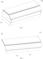
FIG. 1 is a schematic view of an air conditioner indoor unit according to the present application. -
FIG. 2 is a schematic view of a cover assembly in one direction according to the present application. -
FIG. 3 is a schematic view of a cover assembly in another direction according to the present application with a drive motor being covered. -
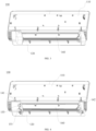
FIG. 4 is a schematic view of a cover assembly in another direction according to the present application with a drive motor being exposed. -
FIG. 5 is a schematic view of a cover assembly in yet another direction according to the present application with a drive motor being exposed). -
FIG. 6 is a schematic view showing that a cover of an air conditioner indoor unit is opened according to the present application. -
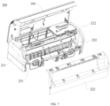
FIG. 7 is an exploded view of an air conditioner indoor unit according to the present application. -
FIG. 8 is another exploded view of an air conditioner indoor unit according to the present application. -
cover assembly 100;front cover 110;lower cover 120;outer air deflector 130;first support 141;second support 142;first motor 151;second motor 152;third motor 153;inner air deflector 160; air outlet 101; air conditionerindoor unit 200;left end cap 211;right end cap 212;front panel 221;lower panel 222;lower base 231;fan 232. - Embodiments of the present application will be described in detail below with reference to examples thereof as illustrated in the accompanying drawings, throughout which same or similar elements, or elements having same or similar functions, are denoted by same or similar reference numerals. The embodiments described below with reference to the drawings are illustrative only, and are intended to explain, rather than limiting, the present application.
- A
cover assembly 100 according to an embodiment of the present application will be described below with reference toFIG. 1 to FIG. 8 . - The
cover assembly 100 according to the present application may be applied to an air conditioner indoor unit. Thecover assembly 100 may include afront cover 110, alower cover 120, and anouter air deflector 130. - The
cover assembly 100 is generally used as a decorative component to cover internal parts and components of the air conditioner, thereby improving an overall appearance of the air conditioner indoor unit to avoid the parts and components of the air conditioner indoor unit from being directly exposed. Thefront cover 110 may be located directly in front of a frame of the air conditioner indoor unit. Thelower cover 120 may be located at a lower side of the air conditioner indoor unit. In an exemplary embodiment of the present application, a front side of thelower cover 120 may be configured as an arc-shaped plate to match a shape of the frame, and the arc-shaped plate may have an air outlet 101. Thelower cover 120 is formed at a lower edge of thefront cover 110. Thelower cover 120 may extend downwardly and rearwardly. A part of thelower cover 120 extending downwardly and rearwardly is the arc-shaped plate as described above. - The
outer air deflector 130 may be mounted on at least one of thefront cover 110 and thelower cover 120 and rotatable relative to thefront cover 110 and/or thelower cover 120. For example, theouter air deflector 130 may be rotatably disposed on thefront cover 110, or theouter air deflector 130 may be rotatably disposed on thelower cover 120 and rotatable relative to thelower cover 120. Alternatively, theouter air deflector 130 may disposed on thefront cover 110 and thelower cover 120 and rotatable relative to thefront cover 110 and thelower cover 120. - Since the
outer air deflector 130 can be mounted on thefront cover 110 and/or thelower cover 120 and rotatable relative to thefront cover 110 and/or thelower cover 120, theouter air deflector 130 can expose or cover the air outlet 101, thereby opening or closing the air outlet 101. In addition, theouter air deflector 130 can adjust an air outlet angle and air outlet volume of the air outlet 101 during a rotation of theouter air deflector 130. - In an exemplary embodiment of the present application, the
outer air deflector 130 has a left end flush with a left end of thefront cover 110 and a right end flush with a right end of thefront cover 110. That is, a dimension of theouter air deflector 130 in a left-right direction is the same as a dimension of thefront cover 110 in the left-right direction. A left edge of theouter air deflector 130 does not extend beyond a left edge of thefront cover 110 or recess relative to the left edge of thefront cover 110, and a right edge of theouter air deflector 130 does not extend beyond a right edge of thefront cover 110 or recess relative to the right edge of thefront cover 110. - In this way, the
cover assembly 100 has a stronger integrity and a better visual appearance. When the air conditioner indoor unit is viewed from the front, fewer boundaries exist between parts and components. Therefore, the entire air conditioner indoor unit is simpler. In an exemplary embodiment of the present application, in the related art, a length dimension of the outer air deflector in the left-right direction is smaller than a length dimension of the front cover in the left-right direction. Therefore, there are boundaries between the outer air deflector and the front cover and the lower cover at an upper side and a lower side of the outer air deflector, respectively, and there are also boundaries between the outer air deflector and the front cover or the lower cover at a left side and a right side of the outer air deflector. - In the present application, there is no boundary between a left side of the
outer air deflector 130 and a left side of thefront cover 110 or a left side of thelower cover 120, and there is no boundary between a right side of theouter air deflector 130 and a right side of thefront cover 110 or a right side of thelower cover 120. Therefore, when the air conditioner indoor unit is viewed from the front, the overall appearance of the air conditioner indoor unit is better and the consistency is better. - According to the
cover assembly 100 of the embodiments of the present application, the left end of theouter air deflector 130 is flush with the left end of thefront cover 110, and the right end of theouter air deflector 130 is flush with the right end of thefront cover 110. Therefore, thecover assembly 100 has a stronger integrity and a better visual appearance. When the air conditioner indoor unit is viewed from the front, fewer boundaries exist between parts and components. Therefore, the air conditioner indoor unit is more integrated, and the entire air conditioner indoor unit is simpler. - It should be noted that the
front cover 110 and thelower cover 120 according to the embodiments of the present application may be constructed into one piece, thereby reducing production difficulty of thecover assembly 100 and improving production efficiency of thecover assembly 100. In addition, thefront cover 110 and thelower cover 120 formed into one piece has a stronger integrity, which further enhances the appearance of the air conditioner indoor unit. - In some embodiments of the present application, the
lower cover 120 is further provided with a support at a rear side of thelower cover 120. The supports includes afirst support 141 and asecond support 142. Thefirst support 141 and thesecond support 142 are not proximate to each other, but are spaced apart from each other by a distance in a left-right direction. The left end and the right end of theouter air deflector 130 are respectively connected to thefirst support 141 and thesecond support 142. In an exemplary embodiment of the present application, the left end of theouter air deflector 130 is rotatable relative to thefirst support 141, and a right end of aninner air deflector 160 is rotatable relative to thesecond support 142. Thus, the left end and the right end of theouter air deflector 130 are mounted on thefirst support 141 and thesecond support 142, respectively. The left end of theouter air deflector 130 is rotatable relative to thefirst support 141, and the right end of theouter air deflector 130 is rotatable relative to thesecond support 142. - Further, a drive member is desired to drive the
outer air deflector 130 to rotate, to allow theouter air deflector 130 to expose or cover the air outlet 101 and adjust the air outlet volume and the air outlet angle of the air outlet 101. - The drive member may include a
first motor 151 and asecond motor 152. Thefirst motor 151 has a motor shaft connected to the left end of theouter air deflector 130, and thesecond motor 152 has a motor shaft connected to the right end of theouter air deflector 130. - Since the
outer air deflector 130 has a large size and a heavy weight, in order to enable theouter air deflector 130 to rotate smoothly, dual motors are designed in the present application to drive theouter air deflector 130 to rotate. Theouter air deflector 130 can rotate faster and more easily by arranging the drive motors at the left end and the right end of theouter air deflector 130. - Further, the
outer air deflector 130 has a rotational axis located below a lower edge of theouter air deflector 130. Further, the rotational axis of theouter air deflector 130 is spaced apart from the lower edge of theouter air deflector 130 by a distance. Therefore, when theouter air deflector 130 is in a closed state, the lower edge of theouter air deflector 130 is closely attached to a lower edge of the air outlet 101 without a gap therebetween, which greatly improves the impression of thecover assembly 100. - It should be noted that the distance between the rotational axis of the
outer air deflector 130 and the lower edge of theouter air deflector 130 should be such that a gap between theouter air deflector 130 and thelower cover 120 is infinitely close to zero when theouter air deflector 130 is in the closed state. Further, the distance between the rotational axis of theouter air deflector 130 and the lower edge of theouter air deflector 130 is dependent on factors including but not limited to a shape of theouter air deflector 130. The distance between the rotational axis of theouter air deflector 130 and the lower edge of theouter air deflector 130 may be adjusted as necessary. Therefore, the distance between the rotational axis of theouter air deflector 130 and the lower edge of theouter air deflector 130 is not limited herein. - In some embodiments of the present application, the
cover assembly 100 further includes aninner air deflector 160. Theinner air deflector 160 may be disposed in a rear of the outer air deflector. Theinner air deflector 160 is disposed on thelower cover 120 and/or thefront cover 110 and rotatable relative to thelower cover 120 and/or thefront cover 110. For example, theinner air deflector 160 is disposed on thefront cover 110 and rotatable relative to theinner air deflector 160, or theinner air deflector 160 is disposed on thelower cover 120 and rotatable relative to theinner air deflector 160, or theinner air deflector 160 is disposed on thefront cover 110 and thelower cover 120 and rotatable relative to thefront cover 110 and thelower cover 120. - The
inner air deflector 160 can completely or partially expose or cover the air outlet 101. That is, theinner air deflector 160 may completely cover or expose the air outlet 101. Of course, theinner air deflector 160 may partially cover or expose the air outlet 101. In the case where theinner air deflector 160 may partially cover or expose the air outlet 101, when theinner air deflector 160 is in the closed state, the air outlet 101 is not completely blocked by theinner air deflector 160, and a part of the air passing through an indoor heat exchanger for heat exchange may flow outwards without passing through theinner air deflector 160. - Further, the
lower cover 120 may be provided with a third support and a fourth support at a rear side surface of thelower cover 120. The third support and the fourth support are not proximate to each other, but are spaced apart from each other in the left-right direction. A left end of theinner air deflector 160 may be connected to the third support, and a right end of theinner air deflector 160 may be connected to the fourth support. In an exemplary embodiment of the present application, the left end of theinner air deflector 160 is rotatable relative to the third support, and the right end of theinner air deflector 160 is rotatable relative to the fourth support. - In some embodiments of the present application, the
first support 141 and the third support may be the same support, and thesecond support 142 and the fourth support may be the same support. That is, the left end of theouter air deflector 130 and the left end of theinner air deflector 160 are both rotatably mounted on the same support, and the right end of theouter air deflector 130 and the right end of theinner air deflector 160 are both rotatably mounted on another same support. - Further, a drive member is required for the
inner air deflector 160 to provide a driving force to rotate theinner air deflector 160. The drive member includes athird motor 153. Thethird motor 153 may be disposed at the third support or the fourth support. Thethird motor 153 has a motor shaft connected to theinner air deflector 160. That is, theinner air deflector 160 is driven by a single motor. It is understood that a size and a weight of theinner air deflector 160 are smaller than the size and the weight of theouter air deflector 130. Therefore, it is enough for theinner air deflector 160 to be driven by the single motor to rotate. - In some embodiments of the present application, a length dimension of the
lower cover 120 in the left-right direction is smaller than a length dimension of thefront cover 110 in the left-right direction. The left end of thelower cover 120 is closer to the right side than the left end of thefront cover 110, and the right end of thelower cover 120 is closer to the left side than the right end of the front cover 11. Therefore, a first notch is formed by the left end of thelower cover 120 and the lower edge of thefront cover 110, and a second notch is formed by the right end of thelower cover 120 and the lower edge of thefront cover 110. - The first notch may avoid a part of a
left end cap 211 extending rightwards and a left end part of alower panel 222. The second notch may avoid a part of aright end cap 212 extending leftwards and a right end part of thelower panel 222. Therefore, it is convenient for theleft end cap 211 and theright end cap 212 to support thecover assembly 100 and thelower panel 222, thereby improving the overall structural strength of the air conditioner indoor unit. - In some embodiments of the present application, the
outer air deflector 130 and/or theinner air deflector 160 has micropores. That is, only theouter air deflector 130 or theinner air deflector 160 may have the micropores, or both theouter air deflector 130 and theinner air deflector 160 may have the micropores. Thus, even if theouter air deflector 130 and/or theinner air deflector 160 are in the closed state, air passing through an indoor heat exchanger for heat exchange may pass through theouter air deflector 130 and/or theinner air deflector 160. - In an exemplary embodiment of the present application, both the
outer air deflector 130 and theinner air deflector 160 have the micropores. Theouter air deflector 130 and theinner air deflector 160 may be in an open state at the same time. In this case, at a constant rotational speed of the fan, air is discharged through the air outlet 101 at a largest velocity, and the air feeling is obvious. When one of theouter air deflector 130 and theinner air deflector 160 is in the closed state, at the constant rotational speed of the fan, the air discharged through the air outlet 101 may pass through the micropores on theouter air deflector 130 or theinner air deflector 160, thereby achieving airstill effect. When both theouter air deflector 130 and theinner air deflector 160 are in the closed state, at the constant rotational speed of the fan, the airstill effect of theouter air deflector 130 and theinner air deflector 160 is the best, thereby greatly improving the use experience for the user. - A
cover assembly 100 according to embodiments of the present application will be described in detail below. - The
cover assembly 100 may include afront cover 110, alower cover 120, and anouter air deflector 130. Thefront cover 110 may be located directly in the front of the frame of an air conditioner indoor unit. Thelower cover 120 may be located at a lower side of the air conditioner indoor unit. In an exemplary embodiment of the present application, a front side of thelower cover 120 may be configured into an arc-shaped plate to match a shape of a frame, and the arc-shaped plate may have an air outlet 101. Thelower cover 120 may be disposed at a lower edge of thefront cover 110 and extend downwards and rearwards. - The
outer air deflector 130 is disposed on thefront cover 110 and/or thelower cover 120 and rotatable relative to thefront cover 110 and/or thelower cover 120. A left end of theouter air deflector 130 is flush with a left end of thefront cover 110, and a right end of theouter air deflector 130 is flush with a right end of thefront cover 110. - The
front cover 110 and thelower cover 120 may be constructed into one piece. Thelower cover 120 is further provided with a support at a rear side of thelower cover 120. The support may include afirst support 141 and asecond support 142. Thefirst support 141 and thesecond support 142 are not proximate to each other, but are spaced apart from each other by a predetermined distance in a left-right direction. The left end and the right end of theouter air deflector 130 are respectively connected to thefirst support 141 and thesecond support 142. In an exemplary embodiment of the present application, the left end of theouter air deflector 130 is rotatable relative to thefirst support 141, and the right end of theinner air deflector 160 is rotatable relative to thesecond support 142. - A rotational axis of the
outer air deflector 130 is located below a lower edge of theouter air deflector 130, and is spaced apart from the lower edge of theouter air deflector 130 by a distance. A distance between the rotational axis of theouter air deflector 130 and the lower edge of theouter air deflector 130 should be such that the gap between theouter air deflector 130 and thelower cover 120 is infinitely close to zero when theouter air deflector 130 is in a closed state. - The
cover assembly 100 may further include aninner air deflector 160. Theinner air deflector 160 may be disposed at in a rear of theouter air deflector 130. Theinner air deflector 160 is disposed on thefront cover 110 and/or thelower cover 120 and rotatable relative to thefront cover 110 and/or thelower cover 120. Theinner air deflector 160 may completely or partially expose or cover the air outlet 101. That is, theinner air deflector 160 may completely expose or cover the air outlet 101, and of course, theinner air deflector 160 may partially cover or expose the air outlet 101. - The
lower cover 120 may be provided with a third support and a fourth support may be disposed at the rear side surface of thelower cover 120. The third support and the fourth support are not proximate to each other but spaced apart from each other in the left-right direction. A left end part of theinner air deflector 160 may be connected to the third support, and a right end part of theinner air deflector 160 may be connected to the fourth support. Thefirst support 141 and the third support may be the same support, and thesecond support 142 and the fourth support may be the same support. - The
first support 141 and the third support may be an integrated piece, and thesecond support 142 and the fourth support may be an integrated piece. In an exemplary embodiment of the present application, thelower cover 120, thefirst support 141, and thesecond support 142 are an integrated piece. Thus, thecover assembly 100 can be easily formed, and thus production efficiency of thecover assembly 100 can be improved. - A length dimension of the
lower cover 120 in the left-right direction is smaller than a length dimension of thefront cover 110 in the left-right direction. The left end of thelower cover 120 is closer to the right side than the left end of thefront cover 110, and the right end of thelower cover 120 is closer to the left side than the right end of thefront cover 110. Therefore, a first notch is formed by the left end of thelower cover 120 and the lower edge of thefront cover 110, and a second notch is formed by the right end of thelower cover 120 and the lower edge of thefront cover 110. Theouter air deflector 130 and/or theinner air deflector 160 has micropores. - An air conditioner
indoor unit 200 according to the embodiments of the present application will be briefly described below. - The air conditioner
indoor unit 200 according to the embodiments of the present application may include a frame and thecover assembly 100. Thecover assembly 100 is disposed at the frame and rotatable relative to the frame. Since the air conditionerindoor unit 200 according to the embodiments of the present application is provided with thecover assembly 100 as described above, the air conditioner indoor unit has good overall impressions and simple appearance. Meanwhile, the air conditioner indoor unit can also have an airstill mode, which greatly improves use experience for a user. - Further, the frame includes a
left end cap 211 and aright end cap 212. Theleft end cap 211 is disposed at a left side of theright end cap 212, and theright end cap 212 is disposed at a right side of theleft end cap 211. Theleft end cap 211 and theright end cap 212 are spaced apart from each other in the left-right direction. - In an exemplary embodiment of the present application, the frame includes the
left end cap 211, theright end cap 212, afront panel 221, and alower panel 222. Theleft end cap 211 and theright end cap 212 are spaced apart from each other in the left-right direction. Both thefront panel 221 and thelower panel 222 are disposed between theleft end cap 211 and theright end cap 212. Thelower panel 222 is disposed below thefront panel 221. Afan 232 is provided between thelower panel 222 and alower base 231. Of course, the fan may be fixed on the lower base. - The
lower panel 222 is disposed at thefront panel 221 and is detachable relative to thelower panel 222. When thefan 232 needs to be disassembled for cleaning, thecover assembly 100 may be rotated to open, and then a lock between thelower panel 222 and thefront panel 221 is unlocked to remove thelower panel 222. Thereafter, a lock between thelower base 231 and thefront panel 221 may be unlocked to remove thelower base 231 and thefan 232 on thelower base 231 together. - In an exemplary embodiment of the present application, the
cover assembly 100 is rotatably mounted on the frame as a whole. Thecover assembly 100 may have an open state and a closed state. When thecover assembly 100 is in the closed state, thecover assembly 100 covers the frame and the parts and components in the frame. When thecover assembly 100 is in the open state, thecover assembly 100 exposes the the parts and components in the frame, facilitating maintenance of the the parts and components in the frame. - A first locking mechanism is provided between the
lower panel 222 and thefront panel 221. Thelower panel 222 may be fixed on thefront panel 221 by the first locking mechanism. Of course, thelower panel 222 may be detached from thefront panel 221 when the first locking mechanism is unlocked. A second locking mechanism is provided between thelower base 231 and thefront panel 221. Thelower base 231 and thefan 232 on thelower base 231 may be fixed to thefront panel 221 by the second locking mechanism. Of course, when the second locking mechanism is unlocked, thelower base 231 and thefan 232 on thelower base 231 may be detached from thefront panel 221. - In an exemplary embodiment of the present application, both the
outer air deflector 130 and theinner air deflector 160 have micropores. Theouter air deflector 130 and theinner air deflector 160 may be in the open state at the same time. In this case, at a constant rotational speed of the fan, air is discharged through the air outlet 101 at a largest velocity, and the air feeling is obvious. When one of theouter air deflector 130 and theinner air deflector 160 is in the closed state, at the constant rotational speed of the fan, the air discharged through the air outlet 101 may pass through the micropores on theouter air deflector 130 or theinner air deflector 160, thereby achieving airstill effect. When both theouter air deflector 130 and theinner air deflector 160 are in the closed state, at the constant rotational speed of the fan, the airstill effect of theouter air deflector 130 and theinner air deflector 160 is the best, thereby greatly improving the use experience for the user. - An air conditioner according to the embodiments of the present application will be briefly described below.
- The air conditioner according to the embodiment of the present application includes the air conditioner indoor unit. Since the air conditioner according to the present application is provided with the air conditioner indoor unit as described above, the overall appearance of the air conditioner is simpler and more beautiful, and various demands of users can be met. Therefore, the use experience for the user is improved.
- Reference throughout this specification to "an embodiment," "some embodiments," "an example," "a specific example," or "some examples," means that a particular feature, structure, material, or characteristic described in connection with the embodiment or example is included in at least one embodiment or example of the present application. The appearances of the above phrases in various places throughout this specification are not necessarily referring to the same embodiment or example of the present application. Furthermore, the particular features, structures, materials, or characteristics may be combined in any suitable manner in one or more embodiments or examples. In addition, different embodiments or examples and features of different embodiments or examples described in the specification may be combined by those skilled in the art without mutual contradiction.
- Although embodiments of the present application have been shown and described above, it should be understood that the above embodiments are merely exemplary, and cannot be construed as limitations of the present application. For those skilled in the art, changes, alternatives, and modifications can be made to the above embodiments without departing from the scope of the present application.
Claims (12)
- A cover assembly of an air conditioner indoor unit, the cover assembly comprising:a front cover disposed at a front side of a frame of the air conditioner indoor unit;a lower cover disposed at a lower edge of the front cover and extending towards a lower side and a rear side of the front cover, the lower cover having an air outlet; andan outer air deflector rotatably disposed on the front cover and/or the lower cover to expose or cover the air outlet, the outer air deflector having a left end flush with a left end of the front cover and a right end flush with a right end of the front cover.
- The cover assembly of the air conditioner indoor unit according to claim 1, wherein:the lower cover is provided with a first support and a second support that are disposed at a rear side surface of the lower cover, the first support and the second support being spaced apart from each other in a left-right direction; andthe left end of the outer air deflector is rotatably mounted on the first support, and the right end of the outer air deflector is rotatably mounted on the second support.
- The cover assembly of the air conditioner indoor unit according to claim 2, wherein:the first support is provided with a first motor, the first motor having a motor shaft connected to the left end of the outer air deflector; andthe second support is provided with a second motor, the second motor having a motor shaft connected to a right end of the inner air deflector.
- The cover assembly of the air conditioner indoor unit according to claim 3, wherein the outer air deflector has a pivot center axis located below a lower edge of the outer air deflector and spaced apart from the lower edge of the outer air deflector.
- The cover assembly of the air conditioner indoor unit according to any one of claims 1 to 4, further comprising an inner air deflector located at a rear side of the outer air deflector, the inner air deflector being rotatably disposed at an inner side of the front cover and/or of the lower cover and configured to at least partially expose or cover the air outlet.
- The cover assembly of the air conditioner indoor unit according to claim 5, wherein:the lower cover is provided with a third support and a fourth support at a rear side surface of the lower cover, the third support and the fourth support being spaced apart from each other in a left-right direction; andthe inner air deflector has a left end rotatably mounted on the third support and a right end rotatably mounted on the fourth support.
- The cover assembly of the air conditioner indoor unit according to claim 6, wherein one of the third support and the fourth support is provided with a third motor, the third motor having a motor shaft connected to the inner air deflector.
- The cover assembly of the air conditioner indoor unit according to any one of claims 1 to 7, wherein:a dimension of the lower cover in a left-right direction is smaller than a dimension of the front cover in the left-right direction;a left end of the lower cover is located at a right side of the left end of the front cover to form a first notch; anda right end of the lower cover is located at a left side of the right end of the front cover to form a second notch.
- The cover assembly of the air conditioner indoor unit according to any one of claims 1 to 8, wherein at least one of the outer air deflector and the inner air deflector has micropores.
- An air conditioner indoor unit, comprising:a frame; andthe cover assembly according to any one of claims 1 to 9, the cover assembly being rotatably disposed at the frame.
- The air conditioner indoor unit according to claim 10, wherein the frame comprises:a left end cap and a right end cap spaced apart from each other in a left-right direction; anda front panel and a lower panel both disposed between the left end cap and the right end cap, the lower panel being detachably disposed at the front panel, and the lower panel being adapted to cover a lower base of the air conditioner indoor unit and a fan disposed at the lower base.
- An air conditioner, comprising the air conditioner indoor unit according to claim 10 or 11.
Applications Claiming Priority (3)
| Application Number | Priority Date | Filing Date | Title |
|---|---|---|---|
| CN202122616442.7U CN216953474U (en) | 2021-10-28 | 2021-10-28 | Machine and air conditioner in face guard subassembly, air conditioning of machine in air conditioning |
| CN202111262782.2A CN116045504B (en) | 2021-10-28 | 2021-10-28 | Mask assembly of air conditioner indoor unit, air conditioner indoor unit and air conditioner |
| PCT/CN2022/083473 WO2023071038A1 (en) | 2021-10-28 | 2022-03-28 | Mask assembly for air conditioner indoor unit, air conditioner indoor unit and air conditioner |
Publications (2)
| Publication Number | Publication Date |
|---|---|
| EP4414623A1 true EP4414623A1 (en) | 2024-08-14 |
| EP4414623A4 EP4414623A4 (en) | 2025-02-12 |
Family
ID=86159033
Family Applications (1)
| Application Number | Title | Priority Date | Filing Date |
|---|---|---|---|
| EP22884955.0A Pending EP4414623A4 (en) | 2021-10-28 | 2022-03-28 | Mask assembly for air conditioner indoor unit, air conditioner indoor unit and air conditioner |
Country Status (2)
| Country | Link |
|---|---|
| EP (1) | EP4414623A4 (en) |
| WO (1) | WO2023071038A1 (en) |
Cited By (1)
| Publication number | Priority date | Publication date | Assignee | Title |
|---|---|---|---|---|
| US20250003606A1 (en) * | 2023-06-27 | 2025-01-02 | Samsung Electronics Co., Ltd. | Air conditioner |
Families Citing this family (1)
| Publication number | Priority date | Publication date | Assignee | Title |
|---|---|---|---|---|
| WO2025138527A1 (en) * | 2023-12-28 | 2025-07-03 | 海信空调有限公司 | Air conditioner |
Family Cites Families (16)
| Publication number | Priority date | Publication date | Assignee | Title |
|---|---|---|---|---|
| JP6359919B2 (en) * | 2014-08-22 | 2018-07-18 | シャープ株式会社 | Air conditioner |
| CN204555028U (en) * | 2015-02-13 | 2015-08-12 | 广东美的制冷设备有限公司 | Indoor apparatus of air conditioner |
| CN204555021U (en) * | 2015-02-13 | 2015-08-12 | 广东美的制冷设备有限公司 | Indoor apparatus of air conditioner |
| KR102403336B1 (en) * | 2015-12-31 | 2022-05-27 | 엘지전자 주식회사 | An air conditioner |
| KR101890869B1 (en) * | 2016-10-27 | 2018-08-22 | 삼성전자주식회사 | Air Conditioner |
| KR102466274B1 (en) * | 2017-04-28 | 2022-11-11 | 삼성전자주식회사 | Air conditioner |
| CN107401776A (en) * | 2017-07-31 | 2017-11-28 | 广东美的制冷设备有限公司 | air conditioner indoor unit |
| CN209263310U (en) * | 2018-12-29 | 2019-08-16 | 广东美的制冷设备有限公司 | Air conditioner indoor unit and air conditioner |
| CN209310128U (en) * | 2018-12-29 | 2019-08-27 | 广东美的制冷设备有限公司 | Air conditioner indoor unit and air conditioner |
| WO2021003830A1 (en) * | 2019-07-08 | 2021-01-14 | 广东美的制冷设备有限公司 | Air conditioner indoor unit and housing assembly used for air conditioner indoor unit |
| CN110701683B (en) * | 2019-11-13 | 2024-12-20 | 广东美的制冷设备有限公司 | Air conditioner indoor unit and air conditioner |
| CN212108670U (en) * | 2019-12-30 | 2020-12-08 | 海信(广东)空调有限公司 | Air conditioner indoor unit |
| CN111140922A (en) * | 2020-01-19 | 2020-05-12 | 广东美的制冷设备有限公司 | Air conditioner indoor unit and air conditioner |
| CN111351132A (en) * | 2020-03-26 | 2020-06-30 | 青岛海尔空调器有限总公司 | Indoor unit of air conditioner |
| CN111351129B (en) * | 2020-03-26 | 2022-04-19 | 青岛海尔空调器有限总公司 | Indoor unit of air conditioner |
| CN212319869U (en) * | 2020-08-05 | 2021-01-08 | 广东美的制冷设备有限公司 | Air conditioner indoor unit and air conditioner |
-
2022
- 2022-03-28 EP EP22884955.0A patent/EP4414623A4/en active Pending
- 2022-03-28 WO PCT/CN2022/083473 patent/WO2023071038A1/en not_active Ceased
Cited By (1)
| Publication number | Priority date | Publication date | Assignee | Title |
|---|---|---|---|---|
| US20250003606A1 (en) * | 2023-06-27 | 2025-01-02 | Samsung Electronics Co., Ltd. | Air conditioner |
Also Published As
| Publication number | Publication date |
|---|---|
| WO2023071038A1 (en) | 2023-05-04 |
| EP4414623A4 (en) | 2025-02-12 |
Similar Documents
| Publication | Publication Date | Title |
|---|---|---|
| JP3669322B2 (en) | Air conditioner indoor unit | |
| EP4414623A1 (en) | Mask assembly for air conditioner indoor unit, air conditioner indoor unit and air conditioner | |
| CN212566012U (en) | Air conditioner indoor unit and air conditioner | |
| CN113803793B (en) | Floor-standing air conditioner indoor unit and air conditioner | |
| CN113007803A (en) | Indoor unit and air conditioner | |
| CN215675463U (en) | Air conditioner | |
| CN210861621U (en) | Non-wind-sensing structure of air conditioner and air conditioner with same | |
| CN210345818U (en) | Air conditioner | |
| CN216953474U (en) | Machine and air conditioner in face guard subassembly, air conditioning of machine in air conditioning | |
| WO2015007101A1 (en) | Floor air conditioner | |
| CN212378103U (en) | Air conditioner air outlet structure and air conditioner | |
| CN215062426U (en) | Air conditioner air guide structure, air conditioner indoor unit and air conditioner | |
| CN116045504B (en) | Mask assembly of air conditioner indoor unit, air conditioner indoor unit and air conditioner | |
| CN220624181U (en) | Wall-mounted air conditioner indoor unit and air conditioner with same | |
| CN208359879U (en) | Air outlet device and vehicle air supply system and vehicle air conditioning system having the same | |
| JP3799799B2 (en) | Embedded ceiling air conditioner | |
| CN215951723U (en) | Air guide assembly and air conditioner indoor unit | |
| CN214746100U (en) | Indoor unit and air conditioner | |
| CN110207259A (en) | Air conditioner indoor unit | |
| CN223375925U (en) | Air conditioner | |
| CN211400252U (en) | Air guide mechanism and air conditioner | |
| CN114251733B (en) | Air conditioner indoor unit and air conditioner | |
| CN222783687U (en) | Air guide plate assembly and air conditioner | |
| CN210688677U (en) | Panel assembly of ceiling machine and ceiling machine with panel assembly | |
| CN211476097U (en) | Air conditioner |
Legal Events
| Date | Code | Title | Description |
|---|---|---|---|
| STAA | Information on the status of an ep patent application or granted ep patent |
Free format text: STATUS: THE INTERNATIONAL PUBLICATION HAS BEEN MADE |
|
| PUAI | Public reference made under article 153(3) epc to a published international application that has entered the european phase |
Free format text: ORIGINAL CODE: 0009012 |
|
| STAA | Information on the status of an ep patent application or granted ep patent |
Free format text: STATUS: REQUEST FOR EXAMINATION WAS MADE |
|
| 17P | Request for examination filed |
Effective date: 20240510 |
|
| AK | Designated contracting states |
Kind code of ref document: A1 Designated state(s): AL AT BE BG CH CY CZ DE DK EE ES FI FR GB GR HR HU IE IS IT LI LT LU LV MC MK MT NL NO PL PT RO RS SE SI SK SM TR |
|
| DAV | Request for validation of the european patent (deleted) | ||
| DAX | Request for extension of the european patent (deleted) | ||
| A4 | Supplementary search report drawn up and despatched |
Effective date: 20250115 |
|
| RIC1 | Information provided on ipc code assigned before grant |
Ipc: F24F 1/0011 20190101ALI20250109BHEP Ipc: F24F 13/14 20060101ALI20250109BHEP Ipc: F24F 13/20 20060101AFI20250109BHEP |