EP4414612A1 - Heating cooker - Google Patents
Heating cooker Download PDFInfo
- Publication number
- EP4414612A1 EP4414612A1 EP22878400.5A EP22878400A EP4414612A1 EP 4414612 A1 EP4414612 A1 EP 4414612A1 EP 22878400 A EP22878400 A EP 22878400A EP 4414612 A1 EP4414612 A1 EP 4414612A1
- Authority
- EP
- European Patent Office
- Prior art keywords
- air
- heating
- heating chamber
- air guide
- circulation fan
- Prior art date
- Legal status (The legal status is an assumption and is not a legal conclusion. Google has not performed a legal analysis and makes no representation as to the accuracy of the status listed.)
- Granted
Links
Images









Classifications
-
- F—MECHANICAL ENGINEERING; LIGHTING; HEATING; WEAPONS; BLASTING
- F24—HEATING; RANGES; VENTILATING
- F24C—DOMESTIC STOVES OR RANGES ; DETAILS OF DOMESTIC STOVES OR RANGES, OF GENERAL APPLICATION
- F24C15/00—Details
- F24C15/32—Arrangements of ducts for hot gases, e.g. in or around baking ovens
- F24C15/322—Arrangements of ducts for hot gases, e.g. in or around baking ovens with forced circulation
- F24C15/325—Arrangements of ducts for hot gases, e.g. in or around baking ovens with forced circulation electrically-heated
-
- H—ELECTRICITY
- H05—ELECTRIC TECHNIQUES NOT OTHERWISE PROVIDED FOR
- H05B—ELECTRIC HEATING; ELECTRIC LIGHT SOURCES NOT OTHERWISE PROVIDED FOR; CIRCUIT ARRANGEMENTS FOR ELECTRIC LIGHT SOURCES, IN GENERAL
- H05B6/00—Heating by electric, magnetic or electromagnetic fields
- H05B6/64—Heating using microwaves
- H05B6/6408—Supports or covers specially adapted for use in microwave heating apparatus
-
- H—ELECTRICITY
- H05—ELECTRIC TECHNIQUES NOT OTHERWISE PROVIDED FOR
- H05B—ELECTRIC HEATING; ELECTRIC LIGHT SOURCES NOT OTHERWISE PROVIDED FOR; CIRCUIT ARRANGEMENTS FOR ELECTRIC LIGHT SOURCES, IN GENERAL
- H05B6/00—Heating by electric, magnetic or electromagnetic fields
- H05B6/64—Heating using microwaves
- H05B6/647—Aspects related to microwave heating combined with other heating techniques
- H05B6/6473—Aspects related to microwave heating combined with other heating techniques combined with convection heating
Definitions
- the present disclosure relates to a heating cooker.
- a heating cooker disclosed in PTL 1 includes a heating chamber, a circulation fan, a convection heater, and a frame.
- the heating chamber can accommodate a heating target.
- the circulation fan sucks air in the heating chamber and blows sucked air into the heating chamber to form a circulation flow passage in an inner space of the heating chamber.
- the convection heater is disposed in front of the circulation fan to heat the air sucked by the circulation fan.
- the frame surrounds the circulation fan and the convection heater.
- An object of the present disclosure is to provide a heating cooker equipped with a hot air circulation mechanism capable of preventing accumulation of residue or detergent.
- the heating cooker of the present disclosure includes a heating chamber, a circulation fan, a convection heater, and an air guide frame.
- the heating chamber can accommodate a heating target.
- the circulation fan sucks air in the heating chamber and blows sucked air into the heating chamber to form a circulation flow passage in an inner space of the heating chamber.
- the convection heater is disposed in front of the circulation fan to heat air sucked from the heating chamber by the circulation fan.
- the air guide frame is a frame having a bottom face with notch and surrounding the circulation fan and the convection heater.
- the present disclosure can provide the heating cooker equipped with the hot air circulation mechanism capable of preventing accumulation of residue or detergent.
- the present disclosure provides a heating cooker equipped with a safe hot air circulation mechanism.
- FIG. 1 is a perspective view of heating cooker 1 in a state where door 4 is closed.
- FIG. 2 is a perspective view of heating cooker 1 in a state where door 4 is opened.
- FIG. 3 is a front view of heating cooker 1 in a state where door 4 is opened.
- a vertical top is defined as top and the side opposite to the top is bottom.
- Right and left of heating cooker 1 seen from a user are defined as right and left.
- a side of heating cooker 1 to the user when the user uses the heating cooker is defined as front and a side opposite to the front is defined as back of heating cooker 1.
- Heating cooker 1 in the exemplary embodiment is a large-output heating cooker for commercial use such as heating cookers used in convenience stores and fast food shops. Heating cooker 1 executes one of microwave heating, radiation heating, and hot air circulation heating or at least two or more sequentially or simultaneously.
- heating cooker 1 includes main body 2, heating chamber 5, machine chamber 3, and door 4.
- Heating chamber 5 is disposed inside main body 2.
- Machine chamber 3 is disposed below heating chamber 5 inside main body 2.
- Door 4 is disposed on a front face of main body 2 to cover a front opening of heating chamber 5.
- Door 4 has handle 24. When the user pulls handle 24 to the front, door 4 opens by rotating about hinges disposed on both sides of door 4 at a lower part.
- Control display 6 is disposed on the front face of main body 2 and displays setting operations by the user and setting information of heating cooker 1.
- a heating target inside heating chamber 5 is heated typically by microwave in a state where door 4 is closed ( FIG. 1 ).
- the heating target is placed inside heating chamber 5 and taken out from heating chamber 5 in a state where door 4 is opened ( FIG. 2 ).
- Heating chamber 5 in main body 2 has a substantially rectangular parallelepiped space with front opening.
- Door 4 covers the front opening to seal heating chamber 5 so that heating chamber 5 can accommodate the heating target to be heated and cooked.
- the heating target is heated and cooked by at least one of a hot air circulation heating mechanism, a radiation heating mechanism, and a microwave heating mechanism.
- the hot air circulation heating mechanism is disposed at the back and near a top face of heating chamber 5.
- the radiation heating mechanism is disposed near the top face of heating chamber 5.
- the microwave heating mechanism is disposed below bottom wall 5a of heating chamber 5.
- Bottom wall 5a of heating chamber 5 is made of a material that easily passes through microwaves, such as glass or ceramic.
- Table 7 for placing the heating target and tray 8 disposed below table 7 can be housed inside heating chamber 5. Tray 8 catches fat and the like dripping from the heating target.
- Table 7 is removable and is, for example, a ceramic table.
- a board-like member for placing the heating target and four legs supporting the board-like member are integrally configured in table 7.
- Tray 8 is fixed on the bottom wall of the main body of the heating cooker.
- Tray 8 is made of ceramic, and more particularly, made of cordierite.
- the cordierite is ceramic constituted of magnesium oxide, aluminum oxide, and silicon oxide, and has low thermal expandability and good thermal shock resistance. Therefore, although a microwave emission is concentrated on a surface of table 7, there is no problem with safety of table 7.
- FIG. 4 is a longitudinal sectional view of heating cooker 1 seen from the front.
- a front side in the drawing is the front of heating cooker 1.
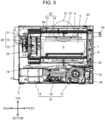
- FIG. 5 is a longitudinal sectional view of heating cooker 1 seen from the left.
- a right side in FIG. 5 is the front of heating cooker 1.
- grill heater 9 configuring a radiation heater is disposed near the top face of heating chamber 5.
- Grill heater 9 is configured with a single sheathed heater bent and disposed near the top face. Grill heater 9 is used in a grill mode (radiation heating) for heating and cooking the heating target by radiation heat.
- microwave heater 21 is disposed inside machine chamber 3.
- Microwave heater 21 includes magnetron 15, inverter 16, and cooling fan 17.
- Microwave heater 21 is controlled by a controller (not illustrated).
- the magnetron generates a microwave.
- Inverter 16 drives magnetron 15.
- Cooling fan 17 takes in air through ventilation panel 30 disposed on a front face of machine chamber 3, and feeds intake air to the back. This air cools inverter 16 and magnetron 15 disposed inside machine chamber 3.
- Microwave heater 21 includes waveguide 18 and microwave supply part 19.
- Waveguide 18 guides the microwave generated by magnetron 15 to below the center of heating chamber 5.
- Microwave supply part 19 is disposed below the center of heating chamber 5, and is an opening formed on a top face at an end of waveguide 18.
- Microwave supply part 19 emits the microwave guided by waveguide 18 to inside heating chamber 5.
- Stirrer 23 is disposed above microwave supply part 19 so as to stir the microwave emitted from microwave supply part 19.
- Stirrer 23 is driven by a stirrer drive unit (not illustrated) and has blades to stir the microwave emitted from microwave supply part 19.
- the stirrer drive unit is a motor disposed inside machine chamber 3.
- the microwave stirred below heating chamber 5 is emitted to inside heating chamber 5 and heats the heating target placed on table 7.
- heating cooker 1 in the exemplary embodiment includes hot air generation mechanism 22 in addition to the radiation heater (grill heater 9) and microwave heater 21.
- Hot air generation mechanism 22 is controlled by a controller (not illustrated) including a microcomputer and semiconductor memory.
- Hot air generation mechanism 22 is disposed inside main body 2 at the back of heating chamber 5, and includes convection heater 10, circulation fan 11, and fan drive unit 12.
- Convection heater 10 is a heat source for hot air circulation heating.
- Circulation fan 11 is an air source.
- Fan drive unit 12 is a motor for driving circulation fan 11. A plurality of openings are created in back wall 5e of heating chamber 5.
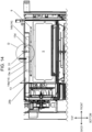
- FIG. 14 is a longitudinal sectional view of a part of heating cooker 1.
- circulation fan 11 When circulation fan 11 is driven, air in heating chamber 5 is sucked through the plurality of openings and the air reaches hot air generation mechanism 22. This air becomes hot air by convection heater 10 and circulation fan 11 in hot air generation mechanism 22. This hot air is blown into heating chamber 5 through outflow port 13d ( FIG. 14 ) created in a bottom wall of air passage 13. The plurality of openings created in back wall 5e will be described later.
- Hot air generation mechanism 22 includes air passage 13 and flow guide 14 described later. Air passage 13 and flow guide 14 are disposed near the top face of heating chamber 5 and define a flow rate and a blowing direction of air from outflow port 13d to heating chamber 5.
- Air passage 13 and flow guide 14 are disposed in an upper part of heating chamber 5 to form an upper space in heating chamber 5 and define a flow rate and a blowing direction of air passing through the upper space and blown into heating chamber 5.
- heating cooker 1 further includes in-chamber temperature detection sensor 50 and empty heating detection sensor 51.
- In-chamber temperature detection sensor 50 is disposed near the top face of heating chamber 5 to detect a temperature inside heating chamber 5.
- Empty heating detection sensor 51 is disposed near the top face of heating chamber 5 and is capable of detecting heating without the heating target in heating chamber 5, a so-called "empty heating”.
- in-chamber temperature detection sensor 50 and empty heating detection sensor 51 are configured with thermistors.
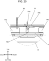
- FIG. 20 is a sectional view of heating chamber 1 in which an area marked with circle D in FIG. 5 is magnified to illustrate a vicinity of in-chamber temperature detection sensor 50 and empty heating detection sensor 51.
- a basic structure of thermistor will be described using in-chamber temperature detection sensor 50 as an example.
- a thermistor chip that will be a detection end of in-chamber temperature detection sensor 50 is housed inside a projecting end of a protective tube (e.g., thin stainless steel tube) with a closed tip.
- An inorganic heat-resistant filler having good heat conductivity is filled in a gap between the thermistor chip and the protective tube.
- In-chamber temperature detection sensor 50 as configured above is disposed upright on flow guide 14 at substantially the center of the top face of heating chamber 5 ( FIG. 14 ).
- a thermal time constant of the thermistor affects responsiveness of the thermistor.
- the thermistor demonstrates better characteristics with smaller thermal time constant.
- the thermistor in the exemplary embodiment has the thermal time constant within 60 seconds including the protective tube.
- the thermistor of empty heating detection sensor 51 also has similar configuration, and thus the description thereof is omitted.
- a position of in-chamber temperature detection sensor 50 is closely related to positions of components of the radiation heater (grill heater 9), microwave heater 21, and hot air generation mechanism 22. More specifically, in-chamber temperature detection sensor 50 is disposed at a predetermined position in a circulation flow passage formed by hot air generation mechanism 22. In-chamber temperature detection sensor 50 detects a temperature at least during the operation of circulation fan 11 in hot air generation mechanism 22.
- a position of empty heating detection sensor 51 is also closely related to the positions of the components of the radiation heater (grill heater 9), microwave heater 21, and hot air generation mechanism 22. More specifically, empty heating detection sensor 51 is disposed at a predetermined position where microwave radiated through bottom wall 5a of heating chamber 5 can be absorbed. Empty heating detection sensor 51 detects empty heating by using a characteristic that the microwave concentrates on dielectric when heating is performed without the heating target in heating chamber 5.
- Hot air generation mechanism 22 further includes air passage 13 and flow guide 14 disposed in heating chamber 5 near the top face. Arrangement, function, and structure of air passage 13 and flow guide 14 that are an air passage inside the heating chamber will be described later.
- FIG. 6 is a front view of back wall 5e of heating chamber 5. As illustrated in FIG. 6 , opening group 25 is created in central area A and upper area B of back wall 5e by punching. Opening group 25 has a shape that inhibit the microwave emitted inside heating chamber 5 from being leaked outside heating chamber 5.
- First opening group 25a is opening group 25 formed in central area A at the center of back wall 5e.
- First opening group 25a has a function as an intake port to suck air inside heating chamber 5 to the back side.
- Second opening group 25b is opening group 25 formed in upper area B extending in a width direction (right-left direction) at an upper part of back wall 5e. Second opening group 25b has a function as a blowing port to blow air (hot air) into heating chamber 5. More specifically, the air is blown through second opening group 25b along air passage 13 toward the upper space in heating chamber 5.
- openings of first opening group 25a and second opening group 25b have the same shape.
- openings of first opening group 25a and second opening group 25b may have a preferred shape according to specifications (e.g., intake quantity and blowing quantity) for heating cooker 1.
- first opening group 25a and second opening group 25b in the exemplary embodiment has an open section formed of an assembly of numerous small openings, and first opening group 25a and second opening group 25b are arranged with a predetermined distance in between.
- the open section may not be the assembly of small openings, and the open section may be one large opening.
- first opening group 25a may be adjacent to second opening group 25b.
- FIG. 7 is a front view of convection device 20 disposed in the hot air circulation heating area.
- FIG. 7 illustrates convection device 20 in a state back wall 5e is removed, and heating chamber 5 will be disposed to the front in FIG. 7 .
- FIG. 8 is a perspective view of convection device 20 disposed in the hot air circulation heating area.
- FIG. 9 to FIG. 12 are perspective views of components of convention device 20. More specifically, FIG. 9 is a perspective view of convection heater 10.
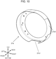
- FIG. 10 is a perspective view of first air guide 27a.
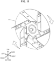
- FIG. 11 is a perspective view of circulation fan 11.
- FIG. 12 is a perspective view of second air guide 27b.
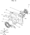
- FIG. 13 is an exploded perspective view of convection device 20.
- convection heater 10 is disposed at the back of back wall 5e. As illustrated in FIG. 9 , convection heater 10 is configured with a spiral sheath heater. A spiral portion of convection heater 10 faces central area A of back wall 5e in FIG. 5 . Convection heater 10 heats air sucked through first opening group 25a in central area A.
- circulation fan 11 and fan drive unit 12 are disposed at the back of convection heater 10.
- Circulation fan 11 is a centrifugal fan that sucks air from a central portion of circulation fan 11 and blows air in a centrifugal direction.
- circulation fan 11 Air sucked from heating chamber 5 by circulation fan 11 is heated by convection heater 10 and becomes hot air. This hot air passes through catalyst 26 for purification, is drawn into circulation fan 11 inside hot air circulation frame 28, and is blown in the centrifugal direction.
- circulation fan 11 rotates clockwise in a front view, which is a view seen from the front.
- Air guide frame 27 includes first air guide 27a ( FIG. 10 ) and second air guide 27b ( FIG. 12 ).
- First air guide 27a is a round frame disposed around convection heater 10.
- Second air guide 27b guides air blown in the centrifugal direction by circulation fan 11 to be blown along the top face of heating chamber 5.
- Air guide frame 27 is fixed onto hot air circulation frame 28 having a square frame shape and surrounding top, bottom, right, and left of air guide frame 27.
- An area defined by a round frame of first air guide 27 faces central area A of back wall 5e.
- the hot air guided to near the top face of heating chamber 5 is sent forward along an inner top face of hot air circulation frame 28.
- Sheet-like third air guide 28a is disposed on an inner side face of the top face of hot air circulation frame 28.
- Third air guide 28a allows the hot air guided to near the top face to be substantially uniformly blown along the top face of heating chamber 5.
- Sheet-like fourth air guide 28b is disposed on a right inner side face of hot air circulation frame 28. Fourth air guide 23b allows the hot air guided to near the top face by second air guide 27b to be blown toward air passage 13.
- hot air circulation frame 28 includes single third air guide 28a and single fourth air guide 28b.
- hot air circulation frame 28 may have a plurality of third air guides 28a and a plurality of fourth air guides 28b.
- third air guide 28a is disposed at a position about 1/3 of a width of the top inner face of hot air circulation frame 28 from the left end of the top inner face of hot air circulation frame 28.
- Fourth air guide 28b is disposed protruding horizontally from an upper part of a right inner side face of hot air circulation frame 28, and guides the hot air to air passage 13.
- Third air guide 28a and fourth air guide 28b are disposed at appropriate positions according to specifications for circulation fan 11 and the shape of hot air circulation frame 28.
- Hot air circulation frame 28 has a heat insulating frame (not illustrated) disposed via a heat insulating material (not illustrated) on an outer periphery of hot air circulation frame 28 in order to prevent heat transmission outside.
- the hot air sucked by circulation fan 11 is blown to near the top face of heating chamber 5, indicated by arrow A2 in FIG. 8 , by second air guide 27b and hot air circulation frame 28 (third air guide 28a and fourth air guide 28b) disposed on an outer side of circulation fan 11.
- Air guide frame 27 has notch 27c on a part of its bottom face.
- residue may accumulate on an inner bottom face of the air guide frame.
- the residue in this case is food residue taken in by circulation fan 11.
- detergent may accumulate or detergent may adhere to the residue accumulated on the inner bottom face of air guide frame 27.
- notch 27c disposed on a part of the bottom face of air guide frame 27 is capable of preventing accumulation of residue or detergent on the air guide frame.
- First air guide 27a that is a round frame, as illustrated in FIG. 10 , is disposed around convection heater 10. First air guide 27a allows air entering inside convection device 20 by circulation fan 11 to pass through convection heater 10.
- First air guide 27a has a substantially cylindrical shape in the exemplary embodiment.
- First air guide 27a has third notch 27d1 to externally extend convection heater 10 inside first air guide 27a.
- First air guide 27a has first notch 27c1 disposed on a part of its bottom face. As illustrated in FIG. 10 , first notch 27c1 is substantially rectangular, and extends from a front edge of first air guide 27a to almost a back edge of first air guide 27a. First notch 27c1 is disposed on a substantially horizontal portion of the bottom face of first air guide 27a.
- the substantially horizontal portion on the bottom face of first air guide 27a is a position closest to the inner bottom face of hot air circulation frame 28.
- Space C (dotted oval circle in FIG. 7 ) is disposed between the bottom face of first air guide 27a and the inner bottom face of hot air circulation frame 28.
- Second air guide 27b is disposed around circulation fan 11 so as to guide air blown in the centrifugal direction of circulation fan 11 to near the top face of heating chamber 5. As illustrated in FIG. 12 , second air guide 27b has a substantially U shape with an opening in its upper part. Second air guide 27b guides air to near the top face of heating chamber 5 through this opening.
- Second air guide 27b has fourth notch 27d2 to extend a part of convection heater 10 disposed inside second air guide 27b to outside second air guide 27b.
- a depth of second air guide 27b is larger than that of first air guide 27a in order to guide the air fed by circulation fan 11 to near the top face of heating chamber 5.
- Second air guide 27b has second notch 27c2 disposed on a part of its bottom. As illustrated in FIG. 12 , second notch 27c2 has a shape and a depth same as first notch 27c1 of first air guide 27a. Second notch 27c2 is disposed on a substantially horizontal portion at the bottom face of second air guide 27b.
- the substantially horizontal portion at the bottom face of second air guide 27b is a position closest to the inner bottom face of hot air circulation frame 28.
- Space C (dotted oval circle in FIG. 7 ) is disposed between the bottom face of second air guide 27b and the inner bottom face of hot air circulation frame 28.
- Second air guide 27b is disposed outside first air guide 27a and partially contacts first air guide 27a. Since second air guide 27b has the opening, first air guide 27a and second air guide 27b contact mostly in a lower half portion. In other words, first air guide 27a is overlaid on the inner side of second air guide 27b having substantially the U shape.
- first air guide 27a and second air guide 27b are arranged to cause a position of first notch 27c1 and a position of second notch 27c2 to mostly overlap in top-bottom, right-left, and front-back directions.
- This structure forms notch 27c of air guide frame 27.
- second notch 27c2 of second air guide 27b may have dimensions larger than that of first notch 27c1 of first air guide 27a in the right-left and front-back directions. Still more, the shape of notch 27c is not limited to rectangular.
- space C is disposed between the bottom face of air guide frame 27 and the bottom face of hot air circulation frame 28, i.e., directly below notch 27c. Therefore, the residue drops through notch 27c to the inner bottom face of hot air circulation frame 28. Accordingly, even when residue enters inside air guide frame 27, the residue can be discharged outside air guide frame 27.
- Notch 27d of air guide frame 27 is formed similarly to notch 27c of air guide frame 27.
- first air guide 27a and second air guide 27b are arranged to cause a position of third notch 27d1 and a position of fourth notch 27d2 to mostly overlap in the top-bottom, right-left, and front-back directions.
- notch 27d of air guide frame 27 is formed.
- Convection heater 10 disposed inside air guide frame 27 can be partially extended outward through notch 27d as formed above.
- hot air is blown from the hot air circulation heating area to near the top face of heating chamber 5. This hot air flows into air passage 13 in hot air generation mechanism 22.
- flow guide 14 forms a hot air path. Air passage 13 and flow guide 14 are disposed in a space formed in an upper part of heating chamber 5.
- FIG. 14 is a longitudinal sectional view of heating cooker 1 illustrating arrangement of air passage 13 and flow guide 14 inside heating chamber 5.
- the left side is the back and the right side is the front. Only a major structure inside heating chamber 5 is illustrated in FIG. 14 .
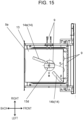
- FIG. 15 is a plan view of the upper space of heating chamber 5 seen from above.
- FIG. 15 illustrates arrangement of air passage 13, flow guide 14, and grill heater 9.
- the hot air flows from the back (left side) to the front (right side).
- the hot air is blown from back wall 5e near the top face of heating chamber 5.
- This hot air flows, at a predetermined wind pressure (flow rate), through a circulation flow passage inside the upper space of heating chamber 5 formed by air passage 13 and flow guide 14.
- Air passage 13 has inflow port 13a disposed on its back side.
- the hot air blown from upper area B of back wall 5e flows into air passage 13 via inflow port 13a.
- This hot air is guided by flow guide 14 and blown at the predetermined wind pressure (flow rate) toward grill heater 9 disposed near the top face of heating chamber 5.
- FIG. 16 is a perspective view of air passage 13.
- FIG. 17 is a longitudinal view of heating cooker 1 illustrating a circulating flow inside heating chamber 5.
- FIG. 17 only illustrates an upper part above machine chamber 3 of heating cooker 1.
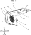
- FIG. 18 is a perspective view of hot air generation mechanism 22.
- air passage 13 includes a plurality of flow guides 14 (first flow guide 14a and second flow guide 14b) and outflow port 13d communicating with heating chamber 5.
- Outflow port 13d is round, in particular, a perfect circle, and is disposed at a position substantially the center of heating chamber 5 in a plan view.
- Air passage 13 forms the upper space partitioned by a plurality of walls, and is configured with upper wall 13e, sheet-like bottom wall 13c, and three side walls.
- the three side walls are side wall 13b1, side wall 13b2, and side wall 13b3.
- Side walls 13b1 to 13b3 are respective side walls to the left, right, and front of air passage 13 in a front view.
- the side wall is not disposed at the back of air passage 13, and inflow port 13a is disposed to let the hot air come in.
- upper wall 13e may be configured with a part of air passage 13 or the top face of heating chamber 5.
- air passage 13 forms a semi-isolated space surrounded by side walls 13b1, 13b2, and 13b3 except for inflow port 13a and outflow port 13d.
- Air passage 13 defines a flow passage of air.
- air passage 13 contacts second opening group 25b at inflow port 13a disposed at its back.
- flow guide 14 includes first flow guide 14a and second flow guide 14b.
- Each of first flow guide 14a and second flow guide 14b includes guide face 14c that defines a path of air blown from circulation fan 11 through second opening group 25b.
- Guide face 14c is disposed substantially perpendicular to bottom wall 13c of air passage 13 ( FIG. 16 ).
- First flow guide 14a is disposed behind outflow port 13d. First flow guide 14a is disposed at a position shifted from the center in the right-left direction (center line P in FIG. 16 ) to a side where a relatively small quantity of air is blown from circulation fan 11 to heating chamber 5.
- Second flow guide 14b is disposed in front of outflow port 13d. Second flow guide 14b is disposed at a position shifted from the center in the right-left direction (center line P in FIG. 16 ) to a side where a relatively large quantity of air is blown from circulation fan 11 to heating chamber 5.
- This arrangement can guide the hot air blown in a plurality of directions to outflow port 13d, and then direct the hot air mostly right downward in heating chamber 5 from outflow port 13d.
- circulation fan 11 is configured to suck air inside heating chamber 5 through the central portion of circulation fan 11 and blow the air in the centrifugal direction.
- First air guide 27a guides air sucked from heating chamber 5 by circulation fan 11 to convection heater 10 via first opening group 25a. This air is heated by convection heater 10 and becomes hot air.
- This hot air passes through catalyst 26 for purification and then is sucked by circulation fan 11 to be blown in the centrifugal direction.
- Second air guide 27b guides the hot air blown from circulation fan 11 to near the top face, and then third air guide 28a guides the hot air along the top face of heating chamber so that the hot air is blown in a substantially uniform manner.
- fourth air guide 28b guides this hot air to air passage 13 through second opening group 25b and inflow port 13a.
- Hot air generation mechanism 22 illustrated in FIG. 18 realizes the above-described airflow.
- the hot air guided by fourth air guide 28b is strongly blown in the centrifugal direction at passing through second opening group 25b by influence of suction by circulation fan 11.
- circulation fan 11 rotates clockwise in the front view in the exemplary embodiment. The airflow will be described below.
- flow guide 14 and side walls 13b1 to 13b3 guide the air entering air passage 13 from the plurality of directions toward outflow port 13d. Accordingly, the hot air is mostly blown right downward without being biased in one direction when the hot air is blown into heating chamber 5. As a result, uneven heating of the heating target placed at the center of heating chamber 5 can be reduced.
- first flow guide 14a is disposed to the back right of outflow port 13d, and extends from near outflow port 13d to the back right.
- Second flow guide 14b is disposed to the front left of outflow port 13d and extends from near outflow port 13d to the front left.
- first flow guide 14a and second flow guide 14b are disposed on the right side and left side, respectively, of center line P relative to the right-left direction of air passage 13.
- first flow guide 14a and second flow guide 14b are disposed on different sides with center line P therebetween relative to the right-left direction of air passage 13.
- angle ⁇ ( ⁇ ⁇ 90°) of first flow guide 14a relative to side wall 13b3 is larger than angle ⁇ ( ⁇ ⁇ 90°) of second flow guide 14b relative to side wall 13b3.
- the above arrangement can prevent air entering from the left side of first flow guide 14a from escaping to the right side of first flow guide 14a and outflow port 13d. Accordingly, a passage to guide air from the left side of first air guide to outflow port 13d can be formed.
- air passage 13 is virtually divided into two left and right areas of flow guide 14 by first flow guide 14a, outflow port 13d, and second flow guide 14b.
- flow guide 14 guides air entering from the left side to outflow port 13d via a passage formed in the left area.
- flow guide 14 can prevent air entering from right side from escaping to the left side of first flow guide 14a and outflow port 13d. Accordingly, a passage to guide air from the right side to outflow port 13d can be formed.
- circulation fan 11 When circulation fan 11 is configured to rotate counterclockwise in the front view, first flow guide 14a and second flow guide 14b in the exemplary embodiment are reversed right and left. Accordingly, an effect similar to the case of clockwise rotation of circulation fan 11 in the front view can be obtained.
- in-chamber temperature detection sensor 50 is disposed at the predetermined position relative to air passage 13 and flow guide 14.
- in-chamber temperature detection sensor 50 detects an in-chamber temperature at least when an air circulation flow passage is established in heating chamber 5 by the operation of circulation fan 11. In other words, in-chamber temperature detection sensor 50 detects the in-chamber temperature when exposed to air circulating in heating chamber 5.
- in-chamber temperature detection sensor 50 When circulation fan 11 is stopped, heating cooker 1 does not perform heating for cooking, and in-chamber temperature detection sensor 50 does not detect the in-chamber temperature.
- a temperature is continuously detected when heating for cooking is not performed, abnormal in-chamber temperature may be erroneously detected due to residual heat of, for example, grill heater 9 in a condition circulation fan 11 is stopped.
- Temperature detection by in-chamber temperature detection sensor 50 is stopped while circulation fan 11 is stopped in order to avoid this erroneous detection.
- In-chamber temperature detection sensor 50 is disposed at a position exposed to circulating air blown through second opening group 25b. In other words, in-chamber temperature detection sensor 50 is disposed inside air passage 13.
- FIG. 19 is an exploded perspective view of hot air generation mechanism 22.
- in-chamber temperature detection sensor 50 is disposed at placement position E and exposed to the circulating air blown through second opening group 25b.
- In-chamber temperature detection sensor 50 is arranged to protrude inside air passage 13 from the top face of air passage 13. This arrangement enables in-chamber temperature detection sensor 50 to accurately detect the temperature of hot air blown by the circulation fan.
- in-chamber temperature detection sensor 50 detects the in-chamber temperature while circulation fan 11 is operated. Stoppage of circulation fan 11 means heating for cooking is stopped. In heating cooker 1, circulation fan 11 operates during heating for cooking even when convection heater 10 is stopped, and thus the air circulation flow passage is established in heating chamber 5 and air passage 13.
- empty heating detection sensor 51 Next, empty heating detection sensor 51 will be described. In an experiment of empty heating detection by the inventors of the present disclosure, a sudden temperature rise is found to be detected immediately after starting microwave heating. Accordingly, "empty heating” is detectable by detecting the sudden temperature rise immediately after starting microwave heating by empty heating detection sensor 51.
- FIG. 21 is an exploded perspective view of empty heating detection sensor 51.
- empty heating detection sensor 51 includes thermistor 51a with protective tube 51c at its tip and dielectric 51b.
- Dielectric 51b has recess 51d to insert protective tube 51c.
- Protective tube 51c is completely covered in recess 51d.
- Thermistor 51a and dielectric 51b have respective sheet-like protrusions to be screwed onto the top face above air passage 13.
- Empty heating detection sensor 51 can detect a sudden temperature rise immediately after starting microwave heating because a temperature of dielectric 51b rises by being heated by microwave.
- Dielectric 51b is not a conductive body and thus has low dielectric constant.
- the dielectric is made of ceramic. More specifically, dielectric 51b is made of cordierite.
- microwave heating When microwave heating is applied to the heating target placed in heating chamber 5, the heating target is heated by absorbing microwave.
- microwave heating is applied to dielectric 5 1b that has smaller capacity than the heating target. Therefore, the temperature of dielectric 51b increases in a short time. As a result, empty heating detection sensor 51 can detect the state of "empty heating” by detecting this sudden temperature rise.
- the sudden temperature rise means that there is a large difference between a detected temperature and a reference in-chamber temperature stored in the controller.
- the reference in-chamber temperature is obtained by multiplying a rotational speed of circulation fan by output power.
- the controller determines a state as "empty heating” when empty heating detection sensor 51 detects the sudden temperature rise in microwave heating, and immediately stops the heating operation. Then, the controller notifies the user that heating cooker 1 is in the state of "empty heating".
- empty heating detection sensor 51 detects the empty heating.
- Thermistor 51a can more accurately detect the temperature rise of dielectric 51b with larger contact area between dielectric 51b and thermistor 51a. As a result, further accurate detection of empty heating becomes feasible.
- Dielectric 51b may partially contact thermistor 51a or the dielectric may cover the thermistor with a space in between.
- dielectric 51b is not limited to the exemplary embodiment.
- detected temperature may vary when air flowing in the passage directly contacts the thermistor. Therefore, a temperature is accurately detectable without a direct contact of air and thermistor by covering thermistor 51a with dielectric 51b..
- the size and shape of dielectric 51b are determined as appropriate according to a heat-resistant temperature of the thermistor to be used and temperature to be measured. Thus, it is necessary to consider a temperature rise of the dielectric according to, for example, output of heating cooker 1 and heating time.
- Empty heating detection sensor 51 is disposed at a position where microwave emitted from underneath heating chamber 5 can be absorbed.
- empty heating detection sensor 51 is disposed vertically above outflow port 13d in air passage 13.
- empty heating detection sensor 51 is disposed at placement position F at substantially the center of the top face of air passage 13 vertically above outflow port 13d ( FIG. 18 ) and protrudes from the top face of air passage 13 to inside air passage 13.
- outflow port 13d is disposed at substantially the center of heating chamber 5. Therefore, empty heating detection sensor 51 can receive microwave from entire heating chamber 5.
- empty heating detection sensor 51 is disposed at placement position F in the exemplary embodiment. Accordingly, the in-chamber temperature of heating chamber 5 is accurately detectable, and "empty heating" during microwave heating can be detected in a short time. As a result, the microwave heating can be stopped before microwave not consumed in heating chamber 5 returns to magnetron 15 and damage magnetron 15.
- in-chamber temperature detection sensor 50 and empty heating detection sensor 51 are disposed at predetermined positions in the circulation flow passage in order to accurately detect the temperature inside heating chamber 5. Accordingly, the in-chamber temperature and its change can be accurately detected. As a result, the heating cooker according to the exemplary embodiment can detect "empty heating" during microwave heating.
- the exemplary embodiment achieves the following advantages.
- the heating cooker includes the heating chamber, the circulation fan, the convection heater, and the air guide frame.
- the heating chamber can accommodate the heating target.
- the circulation fan sucks air in the heating chamber and blows the sucked air into the heating chamber to form the circulation flow passage in the inner space of the heating chamber.
- the convection heater is disposed in front of the circulation fan to heat the air sucked from the heating chamber by the circulation fan.
- the air guide frame is a frame having the bottom face with notch, and surrounds the circulation fan and the convection heater.
- accumulation of residue or detergent in the air guide frame is preventable.
- the notch is disposed on the bottom face of the air guide frame in the substantially horizontal area of the air guide frame in the heating cooker according to the exemplary embodiment.
- the size of notch disposed on the air guide frame can be minimized. As a result, deterioration in performance of the circulation fan due to the notch disposed on the air guide frame can be minimized.
- the air guide frame includes the first air guide that is a substantially cylindrical frame, and the second air guide that feeds the air blown by the circulation fan along the top face of the heating chamber.
- the first air guide has the bottom face with the first notch
- the second air guide has the bottom face with the second notch.
- the first air guide and the second air guide are arranged to cause the first notch and second notch to mostly overlap.
- air can be guided to the center of the circulation fan and also blown along the top face of the heating chamber. Furthermore, the exemplary embodiment can prevent accumulation of residue or detergent on the air guide frame.
- the present disclosure is applicable to heating cookers for heating food, and more particularly, to ovens and microwave ovens.
Landscapes
- Engineering & Computer Science (AREA)
- Chemical & Material Sciences (AREA)
- Combustion & Propulsion (AREA)
- Mechanical Engineering (AREA)
- General Engineering & Computer Science (AREA)
- Physics & Mathematics (AREA)
- Electromagnetism (AREA)
- Electric Ovens (AREA)
- Electric Stoves And Ranges (AREA)
Abstract
Description
- The present disclosure relates to a heating cooker.
- A heating cooker disclosed in
PTL 1 includes a heating chamber, a circulation fan, a convection heater, and a frame. The heating chamber can accommodate a heating target. The circulation fan sucks air in the heating chamber and blows sucked air into the heating chamber to form a circulation flow passage in an inner space of the heating chamber. The convection heater is disposed in front of the circulation fan to heat the air sucked by the circulation fan. The frame surrounds the circulation fan and the convection heater. - PTL 1:
WO 2015/118867 - An object of the present disclosure is to provide a heating cooker equipped with a hot air circulation mechanism capable of preventing accumulation of residue or detergent.
- The heating cooker of the present disclosure includes a heating chamber, a circulation fan, a convection heater, and an air guide frame. The heating chamber can accommodate a heating target. The circulation fan sucks air in the heating chamber and blows sucked air into the heating chamber to form a circulation flow passage in an inner space of the heating chamber. The convection heater is disposed in front of the circulation fan to heat air sucked from the heating chamber by the circulation fan. The air guide frame is a frame having a bottom face with notch and surrounding the circulation fan and the convection heater.
- The present disclosure can provide the heating cooker equipped with the hot air circulation mechanism capable of preventing accumulation of residue or detergent.
-
-
FIG. 1 is a perspective view of a heating cooker in a state where a door is closed according to an exemplary embodiment of the present disclosure. -
FIG. 2 is a perspective view of the heating cooker in a state where the door is opened according to the exemplary embodiment of the present disclosure. -
FIG. 3 is a front view of the heating cooker in a state where the door is opened according to the exemplary embodiment of the present disclosure. -
FIG. 4 is a longitudinal sectional view of the heating cooker according to the exemplary embodiment of the present disclosure. -
FIG. 5 is a longitudinal sectional view of the heating cooker in a state where the door is opened according to the exemplary embodiment of the present disclosure. -
FIG. 6 is a front view of a back wall of a heating chamber. -
FIG. 7 is a front view of a convection device. -
FIG. 8 is a perspective view of the convection device. -
FIG. 9 is a perspective view of a convection heater. -
FIG. 10 is a perspective view of a first air guide. -
FIG. 11 is a perspective view of a circulation fan. -
FIG. 12 is a perspective view of a second air guide. -
FIG. 13 is a development perspective view of the convection device. -
FIG. 14 is a longitudinal sectional view of a part of the heating cooker according to the exemplary embodiment. -
FIG. 15 is a plan view of an upper space of the heating chamber seen from above. -
FIG. 16 is a perspective view of an air passage. -
FIG. 17 is a longitudinal sectional view of the heating cooker according to the exemplary embodiment. -
FIG. 18 is a perspective view of a hot air generation mechanism. -
FIG. 19 is an exploded perspective view of the hot air generation mechanism. -
FIG. 20 is a fragmentary magnified sectional view of the heating cooker according to the exemplary embodiment. -
FIG. 21 is an exploded perspective view of an empty heating detection sensor. - When the inventors have arrived at the present disclosure, a circulation fan is completely surrounded by an air guide frame. With this structure, residue and detergent often remain on an upper bottom face of the air guide frame. Under the circumstances, the inventors have reached the main subject of the present disclosure to solve the above disadvantage. The present disclosure provides a heating cooker equipped with a safe hot air circulation mechanism.
-
Heating cooker 1 according to an exemplary embodiment of the present disclosure is described below with reference to the drawings.FIG. 1 is a perspective view ofheating cooker 1 in a state wheredoor 4 is closed.FIG. 2 is a perspective view ofheating cooker 1 in a state wheredoor 4 is opened.FIG. 3 is a front view ofheating cooker 1 in a state wheredoor 4 is opened. - In the exemplary embodiment, as illustrated in the drawings, a vertical top is defined as top and the side opposite to the top is bottom. Right and left of
heating cooker 1 seen from a user are defined as right and left. A side ofheating cooker 1 to the user when the user uses the heating cooker is defined as front and a side opposite to the front is defined as back ofheating cooker 1. -
Heating cooker 1 in the exemplary embodiment is a large-output heating cooker for commercial use such as heating cookers used in convenience stores and fast food shops.Heating cooker 1 executes one of microwave heating, radiation heating, and hot air circulation heating or at least two or more sequentially or simultaneously. - As illustrated in
FIG. 1 to FIG. 3 ,heating cooker 1 includesmain body 2,heating chamber 5,machine chamber 3, anddoor 4.Heating chamber 5 is disposed insidemain body 2.Machine chamber 3 is disposed belowheating chamber 5 insidemain body 2.Door 4 is disposed on a front face ofmain body 2 to cover a front opening ofheating chamber 5. - Door 4 has handle 24. When the user pulls handle 24 to the front,
door 4 opens by rotating about hinges disposed on both sides ofdoor 4 at a lower part.Control display 6 is disposed on the front face ofmain body 2 and displays setting operations by the user and setting information ofheating cooker 1. - A heating target inside
heating chamber 5 is heated typically by microwave in a state wheredoor 4 is closed (FIG. 1 ). The heating target is placed insideheating chamber 5 and taken out fromheating chamber 5 in a state wheredoor 4 is opened (FIG. 2 ). -
Heating chamber 5 inmain body 2 has a substantially rectangular parallelepiped space with front opening.Door 4 covers the front opening to sealheating chamber 5 so thatheating chamber 5 can accommodate the heating target to be heated and cooked. In this state of housing the heating target, the heating target is heated and cooked by at least one of a hot air circulation heating mechanism, a radiation heating mechanism, and a microwave heating mechanism. - The hot air circulation heating mechanism is disposed at the back and near a top face of
heating chamber 5. The radiation heating mechanism is disposed near the top face ofheating chamber 5. The microwave heating mechanism is disposed belowbottom wall 5a ofheating chamber 5.Bottom wall 5a ofheating chamber 5 is made of a material that easily passes through microwaves, such as glass or ceramic. - Table 7 for placing the heating target and
tray 8 disposed below table 7 can be housed insideheating chamber 5.Tray 8 catches fat and the like dripping from the heating target. - Table 7 is removable and is, for example, a ceramic table. A board-like member for placing the heating target and four legs supporting the board-like member are integrally configured in table 7.
Tray 8 is fixed on the bottom wall of the main body of the heating cooker. -
Tray 8 is made of ceramic, and more particularly, made of cordierite. The cordierite is ceramic constituted of magnesium oxide, aluminum oxide, and silicon oxide, and has low thermal expandability and good thermal shock resistance. Therefore, although a microwave emission is concentrated on a surface of table 7, there is no problem with safety of table 7. -
FIG. 4 is a longitudinal sectional view ofheating cooker 1 seen from the front. In other words, inFIG. 4 , a front side in the drawing is the front ofheating cooker 1.FIG. 5 is a longitudinal sectional view ofheating cooker 1 seen from the left. In other words, a right side inFIG. 5 is the front ofheating cooker 1. - As illustrated in
FIG. 4 andFIG. 5 ,grill heater 9 configuring a radiation heater is disposed near the top face ofheating chamber 5.Grill heater 9 is configured with a single sheathed heater bent and disposed near the top face.Grill heater 9 is used in a grill mode (radiation heating) for heating and cooking the heating target by radiation heat. - In
FIG. 5 ,microwave heater 21 is disposed insidemachine chamber 3.Microwave heater 21 includesmagnetron 15,inverter 16, and coolingfan 17.Microwave heater 21 is controlled by a controller (not illustrated). - The magnetron generates a microwave.
Inverter 16drives magnetron 15. Coolingfan 17 takes in air throughventilation panel 30 disposed on a front face ofmachine chamber 3, and feeds intake air to the back. This air coolsinverter 16 andmagnetron 15 disposed insidemachine chamber 3. -
Microwave heater 21 includeswaveguide 18 andmicrowave supply part 19.Waveguide 18 guides the microwave generated bymagnetron 15 to below the center ofheating chamber 5.Microwave supply part 19 is disposed below the center ofheating chamber 5, and is an opening formed on a top face at an end ofwaveguide 18.Microwave supply part 19 emits the microwave guided bywaveguide 18 toinside heating chamber 5. -
Stirrer 23 is disposed abovemicrowave supply part 19 so as to stir the microwave emitted frommicrowave supply part 19.Stirrer 23 is driven by a stirrer drive unit (not illustrated) and has blades to stir the microwave emitted frommicrowave supply part 19. The stirrer drive unit is a motor disposed insidemachine chamber 3. - Accordingly, the microwave stirred below
heating chamber 5 is emitted toinside heating chamber 5 and heats the heating target placed on table 7. - As illustrated in
FIG. 4 andFIG. 5 ,heating cooker 1 in the exemplary embodiment includes hotair generation mechanism 22 in addition to the radiation heater (grill heater 9) andmicrowave heater 21. Hotair generation mechanism 22 is controlled by a controller (not illustrated) including a microcomputer and semiconductor memory. Hotair generation mechanism 22 is disposed insidemain body 2 at the back ofheating chamber 5, and includesconvection heater 10,circulation fan 11, andfan drive unit 12. -
Convection heater 10 is a heat source for hot air circulation heating.Circulation fan 11 is an air source.Fan drive unit 12 is a motor for drivingcirculation fan 11. A plurality of openings are created inback wall 5e ofheating chamber 5. -
FIG. 14 is a longitudinal sectional view of a part ofheating cooker 1. Whencirculation fan 11 is driven, air inheating chamber 5 is sucked through the plurality of openings and the air reaches hotair generation mechanism 22. This air becomes hot air byconvection heater 10 andcirculation fan 11 in hotair generation mechanism 22. This hot air is blown intoheating chamber 5 throughoutflow port 13d (FIG. 14 ) created in a bottom wall ofair passage 13. The plurality of openings created inback wall 5e will be described later. - Hot
air generation mechanism 22 includesair passage 13 and flow guide 14 described later.Air passage 13 and flowguide 14 are disposed near the top face ofheating chamber 5 and define a flow rate and a blowing direction of air fromoutflow port 13d toheating chamber 5. -
Air passage 13 and flowguide 14 are disposed in an upper part ofheating chamber 5 to form an upper space inheating chamber 5 and define a flow rate and a blowing direction of air passing through the upper space and blown intoheating chamber 5. - As illustrated in
FIG. 14 ,heating cooker 1 further includes in-chambertemperature detection sensor 50 and emptyheating detection sensor 51. In-chambertemperature detection sensor 50 is disposed near the top face ofheating chamber 5 to detect a temperature insideheating chamber 5. Emptyheating detection sensor 51 is disposed near the top face ofheating chamber 5 and is capable of detecting heating without the heating target inheating chamber 5, a so-called "empty heating". For example, in-chambertemperature detection sensor 50 and emptyheating detection sensor 51 are configured with thermistors. -
FIG. 20 is a sectional view ofheating chamber 1 in which an area marked with circle D inFIG. 5 is magnified to illustrate a vicinity of in-chambertemperature detection sensor 50 and emptyheating detection sensor 51. - A basic structure of thermistor will be described using in-chamber
temperature detection sensor 50 as an example. A thermistor chip that will be a detection end of in-chambertemperature detection sensor 50 is housed inside a projecting end of a protective tube (e.g., thin stainless steel tube) with a closed tip. An inorganic heat-resistant filler having good heat conductivity is filled in a gap between the thermistor chip and the protective tube. In-chambertemperature detection sensor 50 as configured above is disposed upright onflow guide 14 at substantially the center of the top face of heating chamber 5 (FIG. 14 ). - A thermal time constant of the thermistor affects responsiveness of the thermistor. The thermistor demonstrates better characteristics with smaller thermal time constant. The thermistor in the exemplary embodiment has the thermal time constant within 60 seconds including the protective tube. The thermistor of empty
heating detection sensor 51 also has similar configuration, and thus the description thereof is omitted. - A position of in-chamber
temperature detection sensor 50 is closely related to positions of components of the radiation heater (grill heater 9),microwave heater 21, and hotair generation mechanism 22. More specifically, in-chambertemperature detection sensor 50 is disposed at a predetermined position in a circulation flow passage formed by hotair generation mechanism 22. In-chambertemperature detection sensor 50 detects a temperature at least during the operation ofcirculation fan 11 in hotair generation mechanism 22. - A position of empty
heating detection sensor 51 is also closely related to the positions of the components of the radiation heater (grill heater 9),microwave heater 21, and hotair generation mechanism 22. More specifically, emptyheating detection sensor 51 is disposed at a predetermined position where microwave radiated throughbottom wall 5a ofheating chamber 5 can be absorbed. Emptyheating detection sensor 51 detects empty heating by using a characteristic that the microwave concentrates on dielectric when heating is performed without the heating target inheating chamber 5. - As described above, the plurality of openings is created in
back wall 5e ofheating chamber 5. A hot air circulation heating area is disposed at the back ofback wall 5e.Convention heater 10,circulation fan 11, andfan drive unit 12 that are components of hotair generation mechanism 22 are disposed in the hot air circulation heating area. Hotair generation mechanism 22 further includesair passage 13 and flow guide 14 disposed inheating chamber 5 near the top face. Arrangement, function, and structure ofair passage 13 and flow guide 14 that are an air passage inside the heating chamber will be described later. -
FIG. 6 is a front view ofback wall 5e ofheating chamber 5. As illustrated inFIG. 6 , openinggroup 25 is created in central area A and upper area B ofback wall 5e by punching.Opening group 25 has a shape that inhibit the microwave emitted insideheating chamber 5 from being leaked outsideheating chamber 5. -
First opening group 25a is openinggroup 25 formed in central area A at the center ofback wall 5e.First opening group 25a has a function as an intake port to suck air insideheating chamber 5 to the back side. -
Second opening group 25b is openinggroup 25 formed in upper area B extending in a width direction (right-left direction) at an upper part ofback wall 5e.Second opening group 25b has a function as a blowing port to blow air (hot air) intoheating chamber 5. More specifically, the air is blown throughsecond opening group 25b alongair passage 13 toward the upper space inheating chamber 5. - In the exemplary embodiment, openings of
first opening group 25a andsecond opening group 25b have the same shape. However, openings offirst opening group 25a andsecond opening group 25b may have a preferred shape according to specifications (e.g., intake quantity and blowing quantity) forheating cooker 1. - Each of
first opening group 25a andsecond opening group 25b in the exemplary embodiment has an open section formed of an assembly of numerous small openings, andfirst opening group 25a andsecond opening group 25b are arranged with a predetermined distance in between. However, the open section may not be the assembly of small openings, and the open section may be one large opening. Still more,first opening group 25a may be adjacent tosecond opening group 25b. -
FIG. 7 is a front view ofconvection device 20 disposed in the hot air circulation heating area.FIG. 7 illustratesconvection device 20 in a stateback wall 5e is removed, andheating chamber 5 will be disposed to the front inFIG. 7 . -
FIG. 8 is a perspective view ofconvection device 20 disposed in the hot air circulation heating area.FIG. 9 to FIG. 12 are perspective views of components ofconvention device 20. More specifically,FIG. 9 is a perspective view ofconvection heater 10.FIG. 10 is a perspective view offirst air guide 27a.FIG. 11 is a perspective view ofcirculation fan 11.FIG. 12 is a perspective view ofsecond air guide 27b.FIG. 13 is an exploded perspective view ofconvection device 20. - As illustrated in
FIG. 7 andFIG. 13 ,convection heater 10 is disposed at the back ofback wall 5e. As illustrated inFIG. 9 ,convection heater 10 is configured with a spiral sheath heater. A spiral portion ofconvection heater 10 faces central area A ofback wall 5e inFIG. 5 .Convection heater 10 heats air sucked throughfirst opening group 25a in central area A. - As illustrated in
FIG. 13 ,circulation fan 11 andfan drive unit 12 are disposed at the back ofconvection heater 10.Circulation fan 11 is a centrifugal fan that sucks air from a central portion ofcirculation fan 11 and blows air in a centrifugal direction. - Air sucked from
heating chamber 5 bycirculation fan 11 is heated byconvection heater 10 and becomes hot air. This hot air passes throughcatalyst 26 for purification, is drawn intocirculation fan 11 inside hotair circulation frame 28, and is blown in the centrifugal direction. In the exemplary embodiment, as illustrated inFIG. 11 ,circulation fan 11 rotates clockwise in a front view, which is a view seen from the front. - As illustrated in
FIG. 13 , a flow guide includingair guide frame 27 and hotair circulation frame 28 is disposed aroundconvection heater 10 andcirculation fan 11.Air guide frame 27 includesfirst air guide 27a (FIG. 10 ) andsecond air guide 27b (FIG. 12 ). -
First air guide 27a is a round frame disposed aroundconvection heater 10.Second air guide 27b guides air blown in the centrifugal direction bycirculation fan 11 to be blown along the top face ofheating chamber 5. -
Air guide frame 27 is fixed onto hotair circulation frame 28 having a square frame shape and surrounding top, bottom, right, and left ofair guide frame 27. An area defined by a round frame offirst air guide 27 faces central area A ofback wall 5e. - Accordingly, air sucked from
heating chamber 5 through central area A ofback wall 5e is heated by convection heater to become hot air, and the hot air is sucked through the central portion ofcirculation fan 11. Then,second air guide 27b disposed aroundcirculation fan 11 guides the hot air sucked bycirculation fan 11 to near the top face ofheating chamber 5. - The hot air guided to near the top face of
heating chamber 5 is sent forward along an inner top face of hotair circulation frame 28. Sheet-likethird air guide 28a is disposed on an inner side face of the top face of hotair circulation frame 28.Third air guide 28a allows the hot air guided to near the top face to be substantially uniformly blown along the top face ofheating chamber 5. - Sheet-like
fourth air guide 28b is disposed on a right inner side face of hotair circulation frame 28. Fourth air guide 23b allows the hot air guided to near the top face bysecond air guide 27b to be blown towardair passage 13. - In the exemplary embodiment, hot
air circulation frame 28 includes singlethird air guide 28a and singlefourth air guide 28b. However, hotair circulation frame 28 may have a plurality of third air guides 28a and a plurality of fourth air guides 28b. - As illustrated in
FIG. 11 ,circulation fan 11 rotates clockwise in a front view. Therefore, to guide the hot air toheating chamber 5,third air guide 28a is disposed at a position about 1/3 of a width of the top inner face of hotair circulation frame 28 from the left end of the top inner face of hotair circulation frame 28. -
Fourth air guide 28b is disposed protruding horizontally from an upper part of a right inner side face of hotair circulation frame 28, and guides the hot air toair passage 13.Third air guide 28a andfourth air guide 28b are disposed at appropriate positions according to specifications forcirculation fan 11 and the shape of hotair circulation frame 28. - Hot
air circulation frame 28 has a heat insulating frame (not illustrated) disposed via a heat insulating material (not illustrated) on an outer periphery of hotair circulation frame 28 in order to prevent heat transmission outside. - As indicated by arrows A1 in
FIG. 8 , air is taken in through the central portion (central area A ofback wall 5e) of the hot air circulation heating area. This air is guided byfirst air guide 27a and heated byconvection heater 10. Then, the hot air is sucked bycirculation fan 11. - The hot air sucked by
circulation fan 11 is blown to near the top face ofheating chamber 5, indicated by arrow A2 inFIG. 8 , bysecond air guide 27b and hot air circulation frame 28 (third air guide 28a andfourth air guide 28b) disposed on an outer side ofcirculation fan 11. -
Air guide frame 27 hasnotch 27c on a part of its bottom face. In a conventional air guide frame withoutnotch 27c, residue may accumulate on an inner bottom face of the air guide frame. The residue in this case is food residue taken in bycirculation fan 11. - Still more, in the conventional air guide frame, detergent may accumulate or detergent may adhere to the residue accumulated on the inner bottom face of
air guide frame 27. - According to the exemplary embodiment,
notch 27c disposed on a part of the bottom face ofair guide frame 27 is capable of preventing accumulation of residue or detergent on the air guide frame. -
First air guide 27a that is a round frame, as illustrated inFIG. 10 , is disposed aroundconvection heater 10.First air guide 27a allows air entering insideconvection device 20 bycirculation fan 11 to pass throughconvection heater 10. -
First air guide 27a has a substantially cylindrical shape in the exemplary embodiment.First air guide 27a has third notch 27d1 to externally extendconvection heater 10 insidefirst air guide 27a. -
First air guide 27a has first notch 27c1 disposed on a part of its bottom face. As illustrated inFIG. 10 , first notch 27c1 is substantially rectangular, and extends from a front edge offirst air guide 27a to almost a back edge offirst air guide 27a. First notch 27c1 is disposed on a substantially horizontal portion of the bottom face offirst air guide 27a. - The substantially horizontal portion on the bottom face of
first air guide 27a is a position closest to the inner bottom face of hotair circulation frame 28. Space C (dotted oval circle inFIG. 7 ) is disposed between the bottom face offirst air guide 27a and the inner bottom face of hotair circulation frame 28. -
Second air guide 27b is disposed aroundcirculation fan 11 so as to guide air blown in the centrifugal direction ofcirculation fan 11 to near the top face ofheating chamber 5. As illustrated inFIG. 12 ,second air guide 27b has a substantially U shape with an opening in its upper part.Second air guide 27b guides air to near the top face ofheating chamber 5 through this opening. -
Second air guide 27b has fourth notch 27d2 to extend a part ofconvection heater 10 disposed insidesecond air guide 27b to outsidesecond air guide 27b. A depth ofsecond air guide 27b is larger than that offirst air guide 27a in order to guide the air fed bycirculation fan 11 to near the top face ofheating chamber 5. -
Second air guide 27b has second notch 27c2 disposed on a part of its bottom. As illustrated inFIG. 12 , second notch 27c2 has a shape and a depth same as first notch 27c1 offirst air guide 27a. Second notch 27c2 is disposed on a substantially horizontal portion at the bottom face ofsecond air guide 27b. - The substantially horizontal portion at the bottom face of
second air guide 27b is a position closest to the inner bottom face of hotair circulation frame 28. Space C (dotted oval circle inFIG. 7 ) is disposed between the bottom face ofsecond air guide 27b and the inner bottom face of hotair circulation frame 28. -
Second air guide 27b is disposed outsidefirst air guide 27a and partially contactsfirst air guide 27a. Sincesecond air guide 27b has the opening,first air guide 27a andsecond air guide 27b contact mostly in a lower half portion. In other words,first air guide 27a is overlaid on the inner side ofsecond air guide 27b having substantially the U shape. - More specifically,
first air guide 27a andsecond air guide 27b are arranged to cause a position of first notch 27c1 and a position of second notch 27c2 to mostly overlap in top-bottom, right-left, and front-back directions. This structure formsnotch 27c ofair guide frame 27. - As described above, a structure that prevents accumulation of residue on the upper bottom face of
first air guide 27a is preferable. Accordingly, the present disclosure is not limited to the above structure. For example, second notch 27c2 ofsecond air guide 27b may have dimensions larger than that of first notch 27c1 offirst air guide 27a in the right-left and front-back directions. Still more, the shape ofnotch 27c is not limited to rectangular. - As illustrated in
FIG. 7 , space C is disposed between the bottom face ofair guide frame 27 and the bottom face of hotair circulation frame 28, i.e., directly belownotch 27c. Therefore, the residue drops throughnotch 27c to the inner bottom face of hotair circulation frame 28. Accordingly, even when residue enters insideair guide frame 27, the residue can be discharged outsideair guide frame 27. -
Notch 27d ofair guide frame 27 is formed similarly to notch 27c ofair guide frame 27. In other words,first air guide 27a andsecond air guide 27b are arranged to cause a position of third notch 27d1 and a position of fourth notch 27d2 to mostly overlap in the top-bottom, right-left, and front-back directions. With this structure,notch 27d ofair guide frame 27 is formed. -
Convection heater 10 disposed insideair guide frame 27 can be partially extended outward throughnotch 27d as formed above. - As described above, hot air is blown from the hot air circulation heating area to near the top face of
heating chamber 5. This hot air flows intoair passage 13 in hotair generation mechanism 22. Inair passage 13, flow guide 14 forms a hot air path.Air passage 13 and flowguide 14 are disposed in a space formed in an upper part ofheating chamber 5. -
FIG. 14 is a longitudinal sectional view ofheating cooker 1 illustrating arrangement ofair passage 13 and flow guide 14 insideheating chamber 5. InFIG. 14 , the left side is the back and the right side is the front. Only a major structure insideheating chamber 5 is illustrated inFIG. 14 . -
FIG. 15 is a plan view of the upper space ofheating chamber 5 seen from above.FIG. 15 illustrates arrangement ofair passage 13,flow guide 14, andgrill heater 9. InFIG. 15 , the hot air flows from the back (left side) to the front (right side). - The hot air is blown from
back wall 5e near the top face ofheating chamber 5. This hot air flows, at a predetermined wind pressure (flow rate), through a circulation flow passage inside the upper space ofheating chamber 5 formed byair passage 13 and flowguide 14. -
Air passage 13 hasinflow port 13a disposed on its back side. The hot air blown from upper area B ofback wall 5e flows intoair passage 13 viainflow port 13a. This hot air is guided byflow guide 14 and blown at the predetermined wind pressure (flow rate) towardgrill heater 9 disposed near the top face ofheating chamber 5. -
FIG. 16 is a perspective view ofair passage 13.FIG. 17 is a longitudinal view ofheating cooker 1 illustrating a circulating flow insideheating chamber 5.FIG. 17 only illustrates an upper part abovemachine chamber 3 ofheating cooker 1.FIG. 18 is a perspective view of hotair generation mechanism 22. - As illustrated in
FIG. 14 to FIG. 16 ,air passage 13 includes a plurality of flow guides 14 (first flow guide 14a andsecond flow guide 14b) andoutflow port 13d communicating withheating chamber 5.Outflow port 13d is round, in particular, a perfect circle, and is disposed at a position substantially the center ofheating chamber 5 in a plan view. -
Air passage 13 forms the upper space partitioned by a plurality of walls, and is configured withupper wall 13e, sheet-like bottom wall 13c, and three side walls. The three side walls are side wall 13b1, side wall 13b2, and side wall 13b3. Side walls 13b1 to 13b3 are respective side walls to the left, right, and front ofair passage 13 in a front view. The side wall is not disposed at the back ofair passage 13, andinflow port 13a is disposed to let the hot air come in. Note thatupper wall 13e may be configured with a part ofair passage 13 or the top face ofheating chamber 5. - With this structure,
air passage 13 forms a semi-isolated space surrounded by side walls 13b1, 13b2, and 13b3 except forinflow port 13a andoutflow port 13d.Air passage 13 defines a flow passage of air. - Air blown through
second opening group 25b flows intoinflow port 13a. As illustrated inFIG. 18 ,air passage 13 contactssecond opening group 25b atinflow port 13a disposed at its back.Inflow port 13a andsecond opening group 25b overlap in a front view. With this structure, air blown bycirculation fan 11 can be taken intoair passage 13 throughsecond opening group 25b. - As illustrated in
FIG. 15 andFIG. 16 , flow guide 14 includesfirst flow guide 14a andsecond flow guide 14b. Each offirst flow guide 14a andsecond flow guide 14b includesguide face 14c that defines a path of air blown fromcirculation fan 11 throughsecond opening group 25b.Guide face 14c is disposed substantially perpendicular tobottom wall 13c of air passage 13 (FIG. 16 ). -
First flow guide 14a is disposed behindoutflow port 13d.First flow guide 14a is disposed at a position shifted from the center in the right-left direction (center line P inFIG. 16 ) to a side where a relatively small quantity of air is blown fromcirculation fan 11 toheating chamber 5. -
Second flow guide 14b is disposed in front ofoutflow port 13d.Second flow guide 14b is disposed at a position shifted from the center in the right-left direction (center line P inFIG. 16 ) to a side where a relatively large quantity of air is blown fromcirculation fan 11 toheating chamber 5. - This arrangement can guide the hot air blown in a plurality of directions to
outflow port 13d, and then direct the hot air mostly right downward inheating chamber 5 fromoutflow port 13d. - In
FIG. 17 , arrows schematically indicate a convection airflow inheating chamber 5 by the operation ofcirculation fan 11. As described above,circulation fan 11 is configured to suck air insideheating chamber 5 through the central portion ofcirculation fan 11 and blow the air in the centrifugal direction. -
First air guide 27a guides air sucked fromheating chamber 5 bycirculation fan 11 toconvection heater 10 viafirst opening group 25a. This air is heated byconvection heater 10 and becomes hot air. - This hot air passes through
catalyst 26 for purification and then is sucked bycirculation fan 11 to be blown in the centrifugal direction.Second air guide 27b guides the hot air blown fromcirculation fan 11 to near the top face, and thenthird air guide 28a guides the hot air along the top face of heating chamber so that the hot air is blown in a substantially uniform manner. - Subsequently,
fourth air guide 28b guides this hot air toair passage 13 throughsecond opening group 25b andinflow port 13a. Hotair generation mechanism 22 illustrated inFIG. 18 realizes the above-described airflow. - The hot air guided by
fourth air guide 28b is strongly blown in the centrifugal direction at passing throughsecond opening group 25b by influence of suction bycirculation fan 11. As described above,circulation fan 11 rotates clockwise in the front view in the exemplary embodiment. The airflow will be described below. - Most of the hot air passing through
second opening group 25b is blown to the front in a direction slightly leftward in the front view (arrows A3). In the hot air indicated by arrows A3, the hot air nearfirst flow guide 14a (arrow A4) is guided tooutflow port 13d byguide face 14c offirst flow guide 14a. - In the hot air indicated by arrows A3, the hot air near side wall 13b1 is guided to
outflow port 13d by side wall 13b1 (arrow A5) orsecond flow guide 14b (arrow A6). - In the hot air passing through
second opening group 25b, the hot air blown to the right offirst flow guide 14a (arrow A7) is guided tooutflow port 13d by side wall 13b2 (arrow A8). - In the hot air blown to the right of
first flow guide 14a (arrow A7), the hot air reaching side wall 13b3 (arrow A9) is guided tooutflow port 13d by side wall 13b3 andsecond flow guide 14b. - In this way, as illustrated in
FIG. 16 ,flow guide 14 and side walls 13b1 to 13b3 guide the air enteringair passage 13 from the plurality of directions towardoutflow port 13d. Accordingly, the hot air is mostly blown right downward without being biased in one direction when the hot air is blown intoheating chamber 5. As a result, uneven heating of the heating target placed at the center ofheating chamber 5 can be reduced. - Next is described a detailed arrangement and direction of flow guide 14 when
circulation fan 11 is configured to rotate clockwise in the front view. In the exemplary embodiment,first flow guide 14a is disposed to the back right ofoutflow port 13d, and extends fromnear outflow port 13d to the back right.Second flow guide 14b is disposed to the front left ofoutflow port 13d and extends fromnear outflow port 13d to the front left. - As illustrated in
FIG. 16 , in a plan view,first flow guide 14a andsecond flow guide 14b are disposed on the right side and left side, respectively, of center line P relative to the right-left direction ofair passage 13. In other words, in the plan view,first flow guide 14a andsecond flow guide 14b are disposed on different sides with center line P therebetween relative to the right-left direction ofair passage 13. - As illustrated in
FIG. 15 , angle α (α < 90°) offirst flow guide 14a relative to side wall 13b3 is larger than angle β (β < 90°) ofsecond flow guide 14b relative to side wall 13b3. - The above arrangement can prevent air entering from the left side of
first flow guide 14a from escaping to the right side offirst flow guide 14a andoutflow port 13d. Accordingly, a passage to guide air from the left side of first air guide tooutflow port 13d can be formed. - Here, in the plan view,
air passage 13 is virtually divided into two left and right areas of flow guide 14 byfirst flow guide 14a,outflow port 13d, andsecond flow guide 14b. In this case, flowguide 14 guides air entering from the left side tooutflow port 13d via a passage formed in the left area. - Furthermore, flow
guide 14 can prevent air entering from right side from escaping to the left side offirst flow guide 14a andoutflow port 13d. Accordingly, a passage to guide air from the right side tooutflow port 13d can be formed. - In other words, in the plan view, when
air passage 13 is divided into two areas byfirst flow guide 14a,outflow port 13d, andsecond flow guide 14b, air entering from the right area is guided tooutflow port 13d via a passage formed in the right area. - When
circulation fan 11 is configured to rotate counterclockwise in the front view,first flow guide 14a andsecond flow guide 14b in the exemplary embodiment are reversed right and left. Accordingly, an effect similar to the case of clockwise rotation ofcirculation fan 11 in the front view can be obtained. - As described above, in-chamber
temperature detection sensor 50 is disposed at the predetermined position relative toair passage 13 and flowguide 14. Inheating cooker 1, in-chambertemperature detection sensor 50 detects an in-chamber temperature at least when an air circulation flow passage is established inheating chamber 5 by the operation ofcirculation fan 11. In other words, in-chambertemperature detection sensor 50 detects the in-chamber temperature when exposed to air circulating inheating chamber 5. - When
circulation fan 11 is stopped,heating cooker 1 does not perform heating for cooking, and in-chambertemperature detection sensor 50 does not detect the in-chamber temperature. When a temperature is continuously detected when heating for cooking is not performed, abnormal in-chamber temperature may be erroneously detected due to residual heat of, for example,grill heater 9 in acondition circulation fan 11 is stopped. Temperature detection by in-chambertemperature detection sensor 50 is stopped whilecirculation fan 11 is stopped in order to avoid this erroneous detection. - In-chamber
temperature detection sensor 50 is disposed at a position exposed to circulating air blown throughsecond opening group 25b. In other words, in-chambertemperature detection sensor 50 is disposed insideair passage 13. -
FIG. 19 is an exploded perspective view of hotair generation mechanism 22. As illustrated inFIG. 19 , in-chambertemperature detection sensor 50 is disposed at placement position E and exposed to the circulating air blown throughsecond opening group 25b. In-chambertemperature detection sensor 50 is arranged to protrude insideair passage 13 from the top face ofair passage 13. This arrangement enables in-chambertemperature detection sensor 50 to accurately detect the temperature of hot air blown by the circulation fan. - As described above, in the exemplary embodiment, in-chamber
temperature detection sensor 50 detects the in-chamber temperature whilecirculation fan 11 is operated. Stoppage ofcirculation fan 11 means heating for cooking is stopped. Inheating cooker 1,circulation fan 11 operates during heating for cooking even whenconvection heater 10 is stopped, and thus the air circulation flow passage is established inheating chamber 5 andair passage 13. - Next, empty
heating detection sensor 51 will be described. In an experiment of empty heating detection by the inventors of the present disclosure, a sudden temperature rise is found to be detected immediately after starting microwave heating. Accordingly, "empty heating" is detectable by detecting the sudden temperature rise immediately after starting microwave heating by emptyheating detection sensor 51. -
FIG. 21 is an exploded perspective view of emptyheating detection sensor 51. As illustrated inFIG. 21 , emptyheating detection sensor 51 includesthermistor 51a withprotective tube 51c at its tip and dielectric 51b. Dielectric 51b hasrecess 51d to insertprotective tube 51c.Protective tube 51c is completely covered inrecess 51d.Thermistor 51a and dielectric 51b have respective sheet-like protrusions to be screwed onto the top face aboveair passage 13. - Empty
heating detection sensor 51 can detect a sudden temperature rise immediately after starting microwave heating because a temperature of dielectric 51b rises by being heated by microwave. Dielectric 51b is not a conductive body and thus has low dielectric constant. For example, the dielectric is made of ceramic. More specifically, dielectric 51b is made of cordierite. - When microwave heating is applied to the heating target placed in
heating chamber 5, the heating target is heated by absorbing microwave. However, in a state of "empty heating" without the heating target inheating chamber 5, microwave heating is applied to dielectric 5 1b that has smaller capacity than the heating target. Therefore, the temperature of dielectric 51b increases in a short time. As a result, emptyheating detection sensor 51 can detect the state of "empty heating" by detecting this sudden temperature rise. - The sudden temperature rise means that there is a large difference between a detected temperature and a reference in-chamber temperature stored in the controller. The reference in-chamber temperature is obtained by multiplying a rotational speed of circulation fan by output power.
- In the exemplary embodiment, the controller determines a state as "empty heating" when empty
heating detection sensor 51 detects the sudden temperature rise in microwave heating, and immediately stops the heating operation. Then, the controller notifies the user thatheating cooker 1 is in the state of "empty heating". - In this way, empty
heating detection sensor 51 detects the empty heating.Thermistor 51a can more accurately detect the temperature rise of dielectric 51b with larger contact area between dielectric 51b andthermistor 51a. As a result, further accurate detection of empty heating becomes feasible. - However, the present disclosure is not limited to this structure. Dielectric 51b may partially contact
thermistor 51a or the dielectric may cover the thermistor with a space in between. Similarly, dielectric 51b is not limited to the exemplary embodiment. - Note that detected temperature may vary when air flowing in the passage directly contacts the thermistor. Therefore, a temperature is accurately detectable without a direct contact of air and thermistor by covering
thermistor 51a with dielectric 51b.. - The size and shape of dielectric 51b are determined as appropriate according to a heat-resistant temperature of the thermistor to be used and temperature to be measured. Thus, it is necessary to consider a temperature rise of the dielectric according to, for example, output of
heating cooker 1 and heating time. - Empty
heating detection sensor 51 is disposed at a position where microwave emitted from underneathheating chamber 5 can be absorbed. In the exemplary embodiment, emptyheating detection sensor 51 is disposed vertically aboveoutflow port 13d inair passage 13. - More specifically, in
heating cooker 1 in the exemplary embodiment, emptyheating detection sensor 51 is disposed at placement position F at substantially the center of the top face ofair passage 13 vertically aboveoutflow port 13d (FIG. 18 ) and protrudes from the top face ofair passage 13 toinside air passage 13. As described above,outflow port 13d is disposed at substantially the center ofheating chamber 5. Therefore, emptyheating detection sensor 51 can receive microwave fromentire heating chamber 5. - As described above, empty
heating detection sensor 51 is disposed at placement position F in the exemplary embodiment. Accordingly, the in-chamber temperature ofheating chamber 5 is accurately detectable, and "empty heating" during microwave heating can be detected in a short time. As a result, the microwave heating can be stopped before microwave not consumed inheating chamber 5 returns tomagnetron 15 anddamage magnetron 15. - As described above, in the exemplary embodiment, in-chamber
temperature detection sensor 50 and emptyheating detection sensor 51 are disposed at predetermined positions in the circulation flow passage in order to accurately detect the temperature insideheating chamber 5. Accordingly, the in-chamber temperature and its change can be accurately detected. As a result, the heating cooker according to the exemplary embodiment can detect "empty heating" during microwave heating. - The exemplary embodiment achieves the following advantages.
- The heating cooker according to the exemplary embodiment includes the heating chamber, the circulation fan, the convection heater, and the air guide frame. The heating chamber can accommodate the heating target. The circulation fan sucks air in the heating chamber and blows the sucked air into the heating chamber to form the circulation flow passage in the inner space of the heating chamber. The convection heater is disposed in front of the circulation fan to heat the air sucked from the heating chamber by the circulation fan. The air guide frame is a frame having the bottom face with notch, and surrounds the circulation fan and the convection heater.
- According to the exemplary embodiment, accumulation of residue or detergent in the air guide frame is preventable.
- The notch is disposed on the bottom face of the air guide frame in the substantially horizontal area of the air guide frame in the heating cooker according to the exemplary embodiment.
- According to the exemplary embodiment, the size of notch disposed on the air guide frame can be minimized. As a result, deterioration in performance of the circulation fan due to the notch disposed on the air guide frame can be minimized.
- In the heating cooker according to the exemplary embodiment, the air guide frame includes the first air guide that is a substantially cylindrical frame, and the second air guide that feeds the air blown by the circulation fan along the top face of the heating chamber. The first air guide has the bottom face with the first notch, and the second air guide has the bottom face with the second notch. The first air guide and the second air guide are arranged to cause the first notch and second notch to mostly overlap.
- According to the exemplary embodiment, air can be guided to the center of the circulation fan and also blown along the top face of the heating chamber. Furthermore, the exemplary embodiment can prevent accumulation of residue or detergent on the air guide frame.
- The present disclosure is applicable to heating cookers for heating food, and more particularly, to ovens and microwave ovens.
-
- 1
- heating cooker
- 2
- main body
- 3
- machine chamber
- 4
- door
- 5
- heating chamber
- 5a
- bottom wall
- 5e
- back wall
- 6
- operation display
- 7
- table
- 8
- tray
- 9
- grill heater
- 10
- convection heater
- 11
- circulation fan
- 12
- fan drive unit
- 13
- air passage
- 13a
- inflow port
- 13b1, 13b2, 3b3
- side wall
- 13c
- bottom wall
- 13d
- outflow port
- 13e
- upper wall
- 14
- flow guide
- 14a
- first flow guide
- 14b
- second flow guide
- 14c
- guide face
- 15
- magnetron
- 16
- inverter
- 17
- cooling fan
- 18
- waveguide
- 19
- microwave supply part
- 20
- convection device
- 21
- microwave heater
- 22
- hot air generation mechanism
- 23
- stirrer
- 24
- handle
- 25
- opening group
- 25a
- first opening group
- 25b
- second opening group
- 26
- catalyst
- 27
- air guide frame
- 27a
- first air guide
- 27b
- second air guide
- 27c
- notch
- 27c1
- first notch
- 27c2
- second notch
- 27d
- notch
- 27d1
- third notch
- 27d2
- fourth notch
- 28
- hot air circulation frame
- 28a
- third air guide
- 28b
- fourth air guide
- 30
- ventilation panel
- 50
- in-chamber temperature detection sensor
- 51
- empty heating detection sensor
- 51a
- thermistor
- 51b
- dielectric
- 51c
- protective tube
- 51d
- recess
Claims (3)
- A heating cooker comprising:a heating chamber configured to accommodate a heating target;a circulation fan configured to suck air in the heating chamber and blow the sucked air into the heating chamber to form a circulation flow passage in an inner space of the heating chamber;a convection heater disposed in front of the circulation fan, the convection heater being configured to heat the air sucked from the heating chamber by the circulation fan; andan air guide frame having a bottom face with a notch, the air guide frame being a frame surrounding the circulation fan and the convection heater.
- The heating cooker of claim 1, wherein
the notch is in a substantially horizontal area of the bottom face of the air guide frame. - The heating cooker of claim 1 or 2, whereinthe air guide frame includes a first air guide that is a substantially cylindrical frame, and a second air guide configured to feed air blown by the circulation fan along a top face of the heating chamber,the first air guide has a bottom face with a first notch, and the second air guide has a bottom face with a second notch, andthe first air guide and the second air guide are arranged to cause the first notch and the second notch to overlap.
Applications Claiming Priority (2)
| Application Number | Priority Date | Filing Date | Title |
|---|---|---|---|
| JP2021163189A JP7557674B2 (en) | 2021-10-04 | 2021-10-04 | Cooking equipment |
| PCT/JP2022/036233 WO2023058530A1 (en) | 2021-10-04 | 2022-09-28 | Heating cooker |
Publications (3)
| Publication Number | Publication Date |
|---|---|
| EP4414612A1 true EP4414612A1 (en) | 2024-08-14 |
| EP4414612A4 EP4414612A4 (en) | 2025-01-08 |
| EP4414612B1 EP4414612B1 (en) | 2025-12-17 |
Family
ID=85803409
Family Applications (1)
| Application Number | Title | Priority Date | Filing Date |
|---|---|---|---|
| EP22878400.5A Active EP4414612B1 (en) | 2021-10-04 | 2022-09-28 | Heating cooker |
Country Status (5)
| Country | Link |
|---|---|
| US (1) | US20250012455A1 (en) |
| EP (1) | EP4414612B1 (en) |
| JP (1) | JP7557674B2 (en) |
| CN (1) | CN117980661A (en) |
| WO (1) | WO2023058530A1 (en) |
Family Cites Families (8)
| Publication number | Priority date | Publication date | Assignee | Title |
|---|---|---|---|---|
| JPH01300144A (en) * | 1988-05-27 | 1989-12-04 | Matsushita Seiko Co Ltd | Discharging device for cooking |
| JP3701839B2 (en) | 2000-04-20 | 2005-10-05 | 株式会社フジマック | Forced convection oven drain structure |
| EP1933095A1 (en) * | 2006-12-08 | 2008-06-18 | Electrolux Home Products Corporation N.V. | Domestic appliance comprising a fan |
| EP2532971A1 (en) * | 2011-06-07 | 2012-12-12 | Koninklijke Philips Electronics N.V. | Apparatus for preparing food |
| KR101469329B1 (en) * | 2012-11-27 | 2014-12-04 | 엘지전자 주식회사 | Gas oven range |
| DE102018123373A1 (en) * | 2018-09-24 | 2020-03-26 | Miele & Cie. Kg | Cooking appliance comprising a cooking space with an intermediate wall |
| JP7149501B2 (en) | 2019-01-10 | 2022-10-07 | パナソニックIpマネジメント株式会社 | heating cooker |
| JP2021025506A (en) | 2019-08-08 | 2021-02-22 | 三菱電機株式会社 | Air blower |
-
2021
- 2021-10-04 JP JP2021163189A patent/JP7557674B2/en active Active
-
2022
- 2022-09-28 WO PCT/JP2022/036233 patent/WO2023058530A1/en not_active Ceased
- 2022-09-28 EP EP22878400.5A patent/EP4414612B1/en active Active
- 2022-09-28 US US18/688,417 patent/US20250012455A1/en active Pending
- 2022-09-28 CN CN202280062341.4A patent/CN117980661A/en active Pending
Also Published As
| Publication number | Publication date |
|---|---|
| WO2023058530A1 (en) | 2023-04-13 |
| CN117980661A (en) | 2024-05-03 |
| US20250012455A1 (en) | 2025-01-09 |
| JP7557674B2 (en) | 2024-09-30 |
| JP2023054385A (en) | 2023-04-14 |
| EP4414612A4 (en) | 2025-01-08 |
| EP4414612B1 (en) | 2025-12-17 |
Similar Documents
| Publication | Publication Date | Title |
|---|---|---|
| EP1431667B1 (en) | Electric oven | |
| JP7149501B2 (en) | heating cooker | |
| EP3343109A1 (en) | Heat cooking device | |
| EP4414612B1 (en) | Heating cooker | |
| EP4414613A1 (en) | Heating cooker | |
| JP6783637B2 (en) | Cooker | |
| JP5694090B2 (en) | Cooker | |
| US20250137657A1 (en) | Heating cooker | |
| US20250244024A1 (en) | Heating cooker | |
| US20250142684A1 (en) | Heating cooker | |
| HK40048105A (en) | Cooking device | |
| JP5996001B2 (en) | Cooker | |
| JP6693025B2 (en) | Heating cooker | |
| US20240074002A1 (en) | Heating cooking apparatus | |
| CN1689374A (en) | Combined toaster and microwave oven and control method thereof | |
| US20250142683A1 (en) | Heating cooker | |
| EP4550934A1 (en) | Heating cooker | |
| HK40048105B (en) | Cooking device | |
| JP2025075284A (en) | heating cooker | |
| JP2005273933A (en) | High frequency cooking device |
Legal Events
| Date | Code | Title | Description |
|---|---|---|---|
| STAA | Information on the status of an ep patent application or granted ep patent |
Free format text: STATUS: THE INTERNATIONAL PUBLICATION HAS BEEN MADE |
|
| PUAI | Public reference made under article 153(3) epc to a published international application that has entered the european phase |
Free format text: ORIGINAL CODE: 0009012 |
|
| STAA | Information on the status of an ep patent application or granted ep patent |
Free format text: STATUS: REQUEST FOR EXAMINATION WAS MADE |
|
| 17P | Request for examination filed |
Effective date: 20240307 |
|
| AK | Designated contracting states |
Kind code of ref document: A1 Designated state(s): AL AT BE BG CH CY CZ DE DK EE ES FI FR GB GR HR HU IE IS IT LI LT LU LV MC MK MT NL NO PL PT RO RS SE SI SK SM TR |
|
| A4 | Supplementary search report drawn up and despatched |
Effective date: 20241206 |
|
| DAV | Request for validation of the european patent (deleted) | ||
| DAX | Request for extension of the european patent (deleted) | ||
| RIC1 | Information provided on ipc code assigned before grant |
Ipc: F24C 15/32 20060101ALI20241202BHEP Ipc: F24C 7/02 20060101ALI20241202BHEP Ipc: F24C 7/00 20060101ALI20241202BHEP Ipc: F24C 1/00 20060101AFI20241202BHEP |
|
| REG | Reference to a national code |
Ref country code: DE Ref legal event code: R079 Free format text: PREVIOUS MAIN CLASS: F24C0001000000 Ipc: F24C0015320000 Ref country code: DE Ref legal event code: R079 Ref document number: 602022027201 Country of ref document: DE Free format text: PREVIOUS MAIN CLASS: F24C0001000000 Ipc: F24C0015320000 |
|
| GRAP | Despatch of communication of intention to grant a patent |
Free format text: ORIGINAL CODE: EPIDOSNIGR1 |
|
| STAA | Information on the status of an ep patent application or granted ep patent |
Free format text: STATUS: GRANT OF PATENT IS INTENDED |
|
| RIC1 | Information provided on ipc code assigned before grant |
Ipc: H05B 6/64 20060101ALI20250508BHEP Ipc: F24C 15/32 20060101AFI20250508BHEP |
|
| INTG | Intention to grant announced |
Effective date: 20250530 |
|
| GRAJ | Information related to disapproval of communication of intention to grant by the applicant or resumption of examination proceedings by the epo deleted |
Free format text: ORIGINAL CODE: EPIDOSDIGR1 |
|
| STAA | Information on the status of an ep patent application or granted ep patent |
Free format text: STATUS: REQUEST FOR EXAMINATION WAS MADE |
|
| GRAS | Grant fee paid |
Free format text: ORIGINAL CODE: EPIDOSNIGR3 |
|
| STAA | Information on the status of an ep patent application or granted ep patent |
Free format text: STATUS: GRANT OF PATENT IS INTENDED |
|
| GRAP | Despatch of communication of intention to grant a patent |
Free format text: ORIGINAL CODE: EPIDOSNIGR1 |
|
| INTC | Intention to grant announced (deleted) | ||
| GRAA | (expected) grant |
Free format text: ORIGINAL CODE: 0009210 |
|
| STAA | Information on the status of an ep patent application or granted ep patent |
Free format text: STATUS: THE PATENT HAS BEEN GRANTED |
|
| INTG | Intention to grant announced |
Effective date: 20251015 |
|
| AK | Designated contracting states |
Kind code of ref document: B1 Designated state(s): AL AT BE BG CH CY CZ DE DK EE ES FI FR GB GR HR HU IE IS IT LI LT LU LV MC MK MT NL NO PL PT RO RS SE SI SK SM TR |
|
| REG | Reference to a national code |
Ref country code: CH Ref legal event code: F10 Free format text: ST27 STATUS EVENT CODE: U-0-0-F10-F00 (AS PROVIDED BY THE NATIONAL OFFICE) Effective date: 20251217 Ref country code: GB Ref legal event code: FG4D |
|
| REG | Reference to a national code |
Ref country code: DE Ref legal event code: R096 Ref document number: 602022027201 Country of ref document: DE |
|
| REG | Reference to a national code |
Ref country code: LT Ref legal event code: MG9D |
|
| PG25 | Lapsed in a contracting state [announced via postgrant information from national office to epo] |
Ref country code: NO Free format text: LAPSE BECAUSE OF FAILURE TO SUBMIT A TRANSLATION OF THE DESCRIPTION OR TO PAY THE FEE WITHIN THE PRESCRIBED TIME-LIMIT Effective date: 20260317 |
|
| PG25 | Lapsed in a contracting state [announced via postgrant information from national office to epo] |
Ref country code: FI Free format text: LAPSE BECAUSE OF FAILURE TO SUBMIT A TRANSLATION OF THE DESCRIPTION OR TO PAY THE FEE WITHIN THE PRESCRIBED TIME-LIMIT Effective date: 20251217 Ref country code: HR Free format text: LAPSE BECAUSE OF FAILURE TO SUBMIT A TRANSLATION OF THE DESCRIPTION OR TO PAY THE FEE WITHIN THE PRESCRIBED TIME-LIMIT Effective date: 20251217 |
|
| PG25 | Lapsed in a contracting state [announced via postgrant information from national office to epo] |
Ref country code: RS Free format text: LAPSE BECAUSE OF FAILURE TO SUBMIT A TRANSLATION OF THE DESCRIPTION OR TO PAY THE FEE WITHIN THE PRESCRIBED TIME-LIMIT Effective date: 20260317 |
|
| REG | Reference to a national code |
Ref country code: NL Ref legal event code: MP Effective date: 20251217 |
|
| PG25 | Lapsed in a contracting state [announced via postgrant information from national office to epo] |
Ref country code: LV Free format text: LAPSE BECAUSE OF FAILURE TO SUBMIT A TRANSLATION OF THE DESCRIPTION OR TO PAY THE FEE WITHIN THE PRESCRIBED TIME-LIMIT Effective date: 20251217 |