EP4414610A1 - Latching mechanism for internally mounted fuel nozzles - Google Patents
Latching mechanism for internally mounted fuel nozzles Download PDFInfo
- Publication number
- EP4414610A1 EP4414610A1 EP24156678.5A EP24156678A EP4414610A1 EP 4414610 A1 EP4414610 A1 EP 4414610A1 EP 24156678 A EP24156678 A EP 24156678A EP 4414610 A1 EP4414610 A1 EP 4414610A1
- Authority
- EP
- European Patent Office
- Prior art keywords
- fuel nozzle
- securing
- bosses
- securing posts
- fuel
- Prior art date
- Legal status (The legal status is an assumption and is not a legal conclusion. Google has not performed a legal analysis and makes no representation as to the accuracy of the status listed.)
- Pending
Links
Images





Classifications
-
- F—MECHANICAL ENGINEERING; LIGHTING; HEATING; WEAPONS; BLASTING
- F23—COMBUSTION APPARATUS; COMBUSTION PROCESSES
- F23R—GENERATING COMBUSTION PRODUCTS OF HIGH PRESSURE OR HIGH VELOCITY, e.g. GAS-TURBINE COMBUSTION CHAMBERS
- F23R3/00—Continuous combustion chambers using liquid or gaseous fuel
- F23R3/28—Continuous combustion chambers using liquid or gaseous fuel characterised by the fuel supply
- F23R3/283—Attaching or cooling of fuel injecting means including supports for fuel injectors, stems, or lances
-
- F—MECHANICAL ENGINEERING; LIGHTING; HEATING; WEAPONS; BLASTING
- F23—COMBUSTION APPARATUS; COMBUSTION PROCESSES
- F23R—GENERATING COMBUSTION PRODUCTS OF HIGH PRESSURE OR HIGH VELOCITY, e.g. GAS-TURBINE COMBUSTION CHAMBERS
- F23R3/00—Continuous combustion chambers using liquid or gaseous fuel
- F23R3/42—Continuous combustion chambers using liquid or gaseous fuel characterised by the arrangement or form of the flame tubes or combustion chambers
Definitions
- FIG. 1 which depicts a combustor portion 180 of a turbine engine
- fuel injectors 100 in accordance with the prior art are typically installed by mounting to an engine case 120 through apertures 191 formed therein.
- the body of each fuel injector 100 is bolted by a flange 160 and provided with a seal 150 between it and the engine case 120.
- the spray tip portion 110 of each fuel injector then fits into a respective aperture formed in the dome 130, and is sealed with a floating grommet 140.
- misalignment often occurs, leaving an asymmetrical gap 193 between the spray tip 110 and floating grommet 140. This condition creates a biased air flow around the nozzle tip, leading to biased sprays which may cause ignition problems, flame stability issues, combustor distress and pattern factor concerns.
- Applicant recognizes the need, therefore, for improved mounting systems that facilitate simpler, faster installation and more accurate alignment of fuel nozzles to respective supporting structures, such as engine combustor domes.
- the devices, systems and methods of the present disclosure provide solutions for these needs.
- devices, systems and methods are provided that simplify and speed turbine engine assembly, while reducing part counts, errors and overall cost.
- a system for mounting a fuel nozzle in a turbine engine includes a fuel nozzle having a body, the body having a plurality of bosses arranged circumferentially about the body, extending radially outwardly therefrom, and a plurality of securing posts arranged circumferentially about a mounting position in the turbine engine, each securing post corresponding to one of the plurality of bosses, at least one of the plurality of securing posts being adapted and configured to resiliently engage a corresponding boss.
- At least one of the plurality of securing posts can include a deflecting portion, adapted and configured to resiliently engage a corresponding boss.
- the deflecting portion can include a pawl portion at a distal end thereof, adapted and configured to capture the corresponding boss, inhibiting inadvertent removal thereof.
- the deflecting portion can function as a rotational stop, substantially inhibiting rotational movement of the fuel nozzle in at least one rotational direction.
- the deflecting portion can be dimensioned to permit a predetermined degree of elastic deformation based on the material from which it is formed.
- At least one of the plurality of securing posts can include a seat, the seat defining the inward most insertion position of the at least one fuel nozzle in the mounting position. At least one of the plurality of securing posts can include a stationary rotational stop, substantially inhibiting rotational movement of the fuel nozzle in at least one rotational direction.
- Three fuel nozzle can be provided with three bosses and the mounting position can be provided with three corresponding securing posts.
- the plurality of bosses and the plurality of securing posts can be arranged circumferentially in a rotationally asymmetric pattern, such that the fuel nozzle can be installed in the mounting position in only one orientation.
- the mounting position can be in a combustor dome.
- the plurality of securing posts can be integrally formed with the combustor dome.
- the securing posts and combustor dome can be integrally formed by an additive manufacturing process.
- Systems in accordance with the invention can further include a plurality of fuel nozzles.
- Systems in accordance with the invention can further include a fuel manifold connected to the plurality of fuel nozzles, said fuel manifold being essentially fully contained within an engine casing of the turbine engine.
- a method of mounting a fuel injector nozzle to a mounting position in a turbine engine includes the steps of providing a fuel nozzle having a body, the body having a plurality of bosses arranged circumferentially about the body, extending radially outwardly therefrom, and providing a plurality of securing posts arranged circumferentially about a mounting position in the turbine engine, each securing post corresponding to one of the plurality of bosses, at least one of the plurality of securing posts being adapted and configured to resiliently engage a corresponding boss.
- the subject methods can further include the step of inserting the fuel nozzle in the mounting position, causing at least one of the plurality of securing posts to resiliently engage a corresponding boss of the fuel nozzle.
- the subject methods can further include the step of rotating the fuel nozzle, rotational force causing the at least one of the plurality of securing posts to deflect and permit a corresponding boss of the fuel nozzle to pass through a restricted opening in the at least one securing post.
- a turbine engine in accordance with still another aspect of the invention, includes a fuel nozzle having a body, the body having a plurality of bosses arranged circumferentially about the body, extending radially outwardly therefrom, and a plurality of securing posts arranged circumferentially about a mounting position in the turbine engine, each securing post corresponding to one of the plurality of bosses, at least one of the plurality of securing posts being adapted and configured to resiliently engage a corresponding boss.
- devices, systems and methods are provided that simplify and shorten installation time of fuel nozzles with their supporting structure(s), typically a dome of a combustor.
- the subject systems, devices and methods further allow for mounting of fuel nozzles internal to an engine case.
- a fuel manifold also installed internal to the engine case, the quantity of penetrations through the engine case is drastically reduced-needing only one for fuel supply to the manifold to supply all injectors, for example.
- the subject systems, devices and methods keep the fuel nozzle tips centered in their mounting positions, drastically reducing biased airflow due to an off-center fuel nozzle.
- Another advantage of the subject systems, devices and methods includes reduction in hardware needed for installation of each fuel nozzle, eliminating the need for various seals, grommets and bolts. Moreover, when used with an internally-mounted fuel manifold, the subject systems and devices help support said manifold without the need for additional brackets or fasteners.
- Figures 2-8 illustrate an exemplary embodiment of a fuel nozzle mounting system in accordance with the present invention, which is designated generally by reference character 200.
- the system 200 includes a fuel nozzle 210 and its supporting structure-which is typically a dome 220 of an engine combustor, as illustrated.
- the dome 220 is provided with securing posts 227, which correspond respectively to bosses 213 of the fuel nozzle 210.
- bosses 213a, 213b, 213c are provided to engage a corresponding number of securing posts, however, this number can vary if need.
- any number of bosses and corresponding posts can be provided.
- any number between about one and twenty can be provided. More particularly between about one and ten can be provided.
- the nozzle 210 includes three bosses 213a, 213b, 213c extending from the body 211 thereof.
- the bosses 213a, 213b, 213c are arranged circumferentially about the body 211, and are spaced apart by predetermined angles ⁇ , ⁇ , ⁇ .
- the bosses 213a, 213b, 213c can be equally spaced apart, or alternatively, and as illustrated, the spacing can be unequal, such that the nozzle 210 can be installed in only one orientation.
- ⁇ is about the same as ⁇ , while ⁇ is greater than ⁇ and ⁇ .
- ⁇ is only slightly greater than the other angles, so that support around the periphery of the body 211 is distributed essentially evenly.
- the body 211 including bosses 213a, 213b, 213c can be manufactured by any suitable processes, including casting, and/or machining, or by way of additive manufacturing techniques. Alternatively, if desired, the bosses 213a, 213b, 213c can be affixed to the body 211 after forming, such as by welding, if desired.
- the materials from which the body 211 include any materials suitable for the conditions that are typically employed in the art, including but not limited to stainless steel alloys, nickel alloys and titanium.
- the dome 220 is provided with securing posts 227a, 227b, 227c corresponding to the bosses 213a, 213b, 213c of nozzle 210.
- the securing posts 227a, 227b, 227c are arranged circumferentially around an aperture 290 provided in the dome 220 for the fuel nozzle 210.
- the spacing of securing posts 227a, 227b, 227c around the aperture 290 corresponds to the spacing of the bosses 213a, 213b, 213c of nozzle 210.
- a seat 229 can be provided in the dome 220 surrounding the aperture 290 and shaped to accommodate a corresponding surface of the fuel nozzle 210.
- Figure 5 is a side view of the fuel nozzle mounting system 200 illustrating an installed state of the nozzle 210 in the dome 220, and engagement of the bosses 213a, 213b, 213c with their respective securing posts 227a, 227b, 227c.
- a representative boss 213 is shown mated with a representative securing post 227.
- the securing post 227 is configured to engage and restrain the boss 213, preventing inadvertent removal or loosening.
- the post 227 as illustrated in Figure 6 , includes a seat 223 for the boss 213, defining the maximum insertion position.
- the boss 213, and in-turn the nozzle 210 is fixed rotationally in one direction by a lateral stop 226, and in the other direction by a deflecting portion 224 of the securing post 227.
- the deflecting portion 224 is imparted with flexibility by a cutout 228, which flexibility allows insertion of the boss 213.
- the deflecting portion 224 then springs back into place and captures the boss 213 with pawl portion 225, inhibiting rotation and removal of the nozzle.
- the securing posts 227 and bosses 213 can be dimensioned such that installation can be simply accomplished by moving the nozzle 210 toward the dome 220 and posts, while rotationally aligning the bosses 213 with the posts 227. Each boss 213 then can rest on the end surface 222 of the post 227. At this point, the nozzle 210 can be rotated, each boss 213 then contacting the lateral edge of the pawl 225 thereof, and thereby deflecting the deflecting portion 224. When deflected sufficiently, the nozzle 210 can then be pushed further into its final seated position, at which point each deflecting portion 224 returns to its original position and captures each respective boss 213.
- the securing posts 227 can be formed as part of the dome, or alternatively part of a smaller attached component.
- the securing posts can be formed by any suitable technique, including casting and/or machining, or alternatively by additive manufacturing techniques.
- the materials from which the securing posts 227 can be formed include any materials suitable for the conditions that are typically employed in the art, including but not limited to stainless steel alloys, nickel alloys and titanium.
- Figure 7 illustrates an alternative embodiment of a securing post 727 in accordance with the invention.
- a representative boss 213 is shown mated with the securing post 727.
- the configuration and function of the securing post 727 is similar to that of figure 6 , except that bevels 723, 725 are provided at the end portion of the securing post 727 to facilitate installation of a fuel nozzle 210 by guiding and aligning each of the bosses 213 during installation.
- Figure 8 illustrates an alternative embodiment of a securing post 827 in accordance with the invention.
- a representative boss 213 is shown mated with the securing post 827.
- the configuration and function of the securing post 827 is similar to that of the preceding figures, except that two opposing deflecting portions 824a, 824b are provided- each of them deflecting during insertion of the nozzle 210, as the boss 213 bosses therebetween.
- the deflection needed to allow the boss 213 to pass by is absorbed by two deflecting portions 824a, 824b, thereby requiring less deflection of either individual deflecting portion.
- Such an arrangement may be beneficial in cases where stiffer materials are used, or a shorter overall securing post height is desired, leaving each deflecting portion shorter and therefore unable to deflect as far as a longer deflecting portion.
Landscapes
- Engineering & Computer Science (AREA)
- Chemical & Material Sciences (AREA)
- Combustion & Propulsion (AREA)
- Mechanical Engineering (AREA)
- General Engineering & Computer Science (AREA)
- Fuel-Injection Apparatus (AREA)
Abstract
A system for mounting a fuel nozzle (210) in a turbine engine includes a fuel nozzle (210) having a body, the body having a plurality of bosses arranged circumferentially about the body, extending radially outwardly therefrom, and a plurality of securing posts (227a-c) arranged circumferentially about a mounting position in the turbine engine, each securing post corresponding to one of the plurality of bosses, at least one of the plurality of securing posts (227a-c) being adapted and configured to resiliently engage a corresponding boss.
Description
- As illustrated in
Figure 1 , which depicts acombustor portion 180 of a turbine engine,fuel injectors 100 in accordance with the prior art are typically installed by mounting to anengine case 120 throughapertures 191 formed therein. The body of eachfuel injector 100 is bolted by aflange 160 and provided with aseal 150 between it and theengine case 120. Thespray tip portion 110 of each fuel injector then fits into a respective aperture formed in thedome 130, and is sealed with a floatinggrommet 140. However, misalignment often occurs, leaving anasymmetrical gap 193 between thespray tip 110 and floatinggrommet 140. This condition creates a biased air flow around the nozzle tip, leading to biased sprays which may cause ignition problems, flame stability issues, combustor distress and pattern factor concerns. - Applicant recognizes the need, therefore, for improved mounting systems that facilitate simpler, faster installation and more accurate alignment of fuel nozzles to respective supporting structures, such as engine combustor domes. The devices, systems and methods of the present disclosure provide solutions for these needs.
- In accordance with the present invention, devices, systems and methods are provided that simplify and speed turbine engine assembly, while reducing part counts, errors and overall cost.
- In accordance with one aspect of the invention, a system for mounting a fuel nozzle in a turbine engine includes a fuel nozzle having a body, the body having a plurality of bosses arranged circumferentially about the body, extending radially outwardly therefrom, and a plurality of securing posts arranged circumferentially about a mounting position in the turbine engine, each securing post corresponding to one of the plurality of bosses, at least one of the plurality of securing posts being adapted and configured to resiliently engage a corresponding boss.
- At least one of the plurality of securing posts can include a deflecting portion, adapted and configured to resiliently engage a corresponding boss. The deflecting portion can include a pawl portion at a distal end thereof, adapted and configured to capture the corresponding boss, inhibiting inadvertent removal thereof. The deflecting portion can function as a rotational stop, substantially inhibiting rotational movement of the fuel nozzle in at least one rotational direction. The deflecting portion can be dimensioned to permit a predetermined degree of elastic deformation based on the material from which it is formed.
- At least one of the plurality of securing posts can include a seat, the seat defining the inward most insertion position of the at least one fuel nozzle in the mounting position. At least one of the plurality of securing posts can include a stationary rotational stop, substantially inhibiting rotational movement of the fuel nozzle in at least one rotational direction. Three fuel nozzle can be provided with three bosses and the mounting position can be provided with three corresponding securing posts.
- The plurality of bosses and the plurality of securing posts can be arranged circumferentially in a rotationally asymmetric pattern, such that the fuel nozzle can be installed in the mounting position in only one orientation.
- The mounting position can be in a combustor dome. The plurality of securing posts can be integrally formed with the combustor dome. The securing posts and combustor dome can be integrally formed by an additive manufacturing process.
- Systems in accordance with the invention can further include a plurality of fuel nozzles. Systems in accordance with the invention can further include a fuel manifold connected to the plurality of fuel nozzles, said fuel manifold being essentially fully contained within an engine casing of the turbine engine.
- In accordance with a further aspect of the invention, a method of mounting a fuel injector nozzle to a mounting position in a turbine engine includes the steps of providing a fuel nozzle having a body, the body having a plurality of bosses arranged circumferentially about the body, extending radially outwardly therefrom, and providing a plurality of securing posts arranged circumferentially about a mounting position in the turbine engine, each securing post corresponding to one of the plurality of bosses, at least one of the plurality of securing posts being adapted and configured to resiliently engage a corresponding boss.
- The subject methods can further include the step of inserting the fuel nozzle in the mounting position, causing at least one of the plurality of securing posts to resiliently engage a corresponding boss of the fuel nozzle. The subject methods can further include the step of rotating the fuel nozzle, rotational force causing the at least one of the plurality of securing posts to deflect and permit a corresponding boss of the fuel nozzle to pass through a restricted opening in the at least one securing post.
- In accordance with still another aspect of the invention, a turbine engine, includes a fuel nozzle having a body, the body having a plurality of bosses arranged circumferentially about the body, extending radially outwardly therefrom, and a plurality of securing posts arranged circumferentially about a mounting position in the turbine engine, each securing post corresponding to one of the plurality of bosses, at least one of the plurality of securing posts being adapted and configured to resiliently engage a corresponding boss.
- So that those skilled in the art to which the subject disclosure appertains will readily understand how to make and use the devices, systems and methods of the subject disclosure without undue experimentation, embodiments thereof will be described in detail below with reference to certain figures, wherein:
-
Figure 1 is a cross-sectional view of a portion of a combustor of a turbine engine, showing a fuel injector with nozzle installed through an engine casing and into a dome of a combustor of the engine, in accordance with the prior art; -
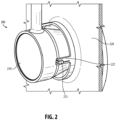
Figure 2 is an isometric view of a fuel nozzle aligned and engaged with a corresponding portion of an engine combustor dome, in accordance with the invention; -
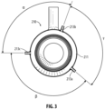
Figure 3 is a bottom view of a fuel nozzle in accordance with the invention showing a plurality of supporting bosses for engaging corresponding securing posts on the combustor dome; -
Figure 4 is an isometric view of a portion of an engine combustor dome in accordance with the present invention showing a plurality of securing posts for engaging respective bosses on a fuel nozzle; -
Figure 5 is a side view of a fuel nozzle aligned and engaged with a corresponding portion of an engine combustor dome, in accordance with the invention; -
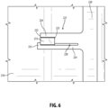
Figure 6 is a detail side view of a fuel nozzle aligned and engaged with a corresponding portion of an engine combustor dome, showing one embodiment of securing posts in accordance with the invention; -
Figure 7 is a detail side view of a fuel nozzle aligned and engaged with a corresponding portion of an engine combustor dome, showing another embodiment of securing posts in accordance with the invention; and -
Figure 8 is a detail side view of a fuel nozzle aligned and engaged with a corresponding portion of an engine combustor dome, showing still another embodiment of securing posts in accordance with the invention. - Reference will now be made to the drawings wherein like reference numerals identify similar structural features or aspects of the subject disclosure.
- In accordance with the present invention, devices, systems and methods are provided that simplify and shorten installation time of fuel nozzles with their supporting structure(s), typically a dome of a combustor.
- The subject systems, devices and methods further allow for mounting of fuel nozzles internal to an engine case. In conjunction with a fuel manifold also installed internal to the engine case, the quantity of penetrations through the engine case is drastically reduced-needing only one for fuel supply to the manifold to supply all injectors, for example.
- Additionally, the subject systems, devices and methods keep the fuel nozzle tips centered in their mounting positions, drastically reducing biased airflow due to an off-center fuel nozzle.
- Another advantage of the subject systems, devices and methods includes reduction in hardware needed for installation of each fuel nozzle, eliminating the need for various seals, grommets and bolts. Moreover, when used with an internally-mounted fuel manifold, the subject systems and devices help support said manifold without the need for additional brackets or fasteners.
- The aforementioned benefits are heightened when large quantities of nozzles are used, such as is the trajectory of the art. Whereas engines have in the past included 15-20 fuel nozzles, engines can now include 60 or more fuel nozzles. Therefore, any economization of time or materials in installation of one fuel nozzle is realized many times over. Moreover, expenditures of time and concomitant frustration of precisely aligning large quantities of fuel nozzles are advantageously eliminated through use of the subject systems, devices and methods.
- For purposes of explanation and illustration, and not limitation,
Figures 2-8 illustrate an exemplary embodiment of a fuel nozzle mounting system in accordance with the present invention, which is designated generally byreference character 200. With reference toFigure 2 , thesystem 200 includes afuel nozzle 210 and its supporting structure-which is typically adome 220 of an engine combustor, as illustrated. Thedome 220 is provided with securingposts 227, which correspond respectively tobosses 213 of thefuel nozzle 210. - With reference to
Figure 3 , threebosses nozzle 210 includes threebosses body 211 thereof. Thebosses body 211, and are spaced apart by predetermined angles α, β, γ. Thebosses nozzle 210 can be installed in only one orientation. In the embodiment ofFigure 3 , α is about the same as β, while γ is greater than α and β. In accordance with a preferred aspect, γ is only slightly greater than the other angles, so that support around the periphery of thebody 211 is distributed essentially evenly. - The
body 211, includingbosses bosses body 211 after forming, such as by welding, if desired. The materials from which thebody 211 include any materials suitable for the conditions that are typically employed in the art, including but not limited to stainless steel alloys, nickel alloys and titanium. - With reference to
Figure 4 , thedome 220 is provided with securingposts bosses nozzle 210. The securingposts aperture 290 provided in thedome 220 for thefuel nozzle 210. Naturally, the spacing of securingposts aperture 290 corresponds to the spacing of thebosses nozzle 210. Aseat 229 can be provided in thedome 220 surrounding theaperture 290 and shaped to accommodate a corresponding surface of thefuel nozzle 210. -
Figure 5 is a side view of the fuelnozzle mounting system 200 illustrating an installed state of thenozzle 210 in thedome 220, and engagement of thebosses respective securing posts - With reference to
Figure 6 , arepresentative boss 213 is shown mated with a representative securingpost 227. The securingpost 227 is configured to engage and restrain theboss 213, preventing inadvertent removal or loosening. Thepost 227, as illustrated inFigure 6 , includes aseat 223 for theboss 213, defining the maximum insertion position. Theboss 213, and in-turn thenozzle 210, is fixed rotationally in one direction by alateral stop 226, and in the other direction by a deflectingportion 224 of the securingpost 227. The deflectingportion 224 is imparted with flexibility by acutout 228, which flexibility allows insertion of theboss 213. The deflectingportion 224 then springs back into place and captures theboss 213 withpawl portion 225, inhibiting rotation and removal of the nozzle. - In accordance with a preferred aspect of the invention, the securing
posts 227 andbosses 213 can be dimensioned such that installation can be simply accomplished by moving thenozzle 210 toward thedome 220 and posts, while rotationally aligning thebosses 213 with theposts 227. Eachboss 213 then can rest on theend surface 222 of thepost 227. At this point, thenozzle 210 can be rotated, eachboss 213 then contacting the lateral edge of thepawl 225 thereof, and thereby deflecting the deflectingportion 224. When deflected sufficiently, thenozzle 210 can then be pushed further into its final seated position, at which point each deflectingportion 224 returns to its original position and captures eachrespective boss 213. - The securing posts 227 can be formed as part of the dome, or alternatively part of a smaller attached component. In accordance with the invention, the securing posts can be formed by any suitable technique, including casting and/or machining, or alternatively by additive manufacturing techniques. The materials from which the securing
posts 227 can be formed include any materials suitable for the conditions that are typically employed in the art, including but not limited to stainless steel alloys, nickel alloys and titanium. -
Figure 7 illustrates an alternative embodiment of a securingpost 727 in accordance with the invention. As with the embodiment illustrated in the preceding figures, arepresentative boss 213 is shown mated with the securingpost 727. The configuration and function of the securingpost 727 is similar to that offigure 6 , except that bevels 723, 725 are provided at the end portion of the securingpost 727 to facilitate installation of afuel nozzle 210 by guiding and aligning each of thebosses 213 during installation. -
Figure 8 illustrates an alternative embodiment of a securingpost 827 in accordance with the invention. As with the embodiment illustrated in the preceding figures, arepresentative boss 213 is shown mated with the securingpost 827. The configuration and function of the securingpost 827 is similar to that of the preceding figures, except that two opposing deflectingportions nozzle 210, as theboss 213 bosses therebetween. In this manner, the deflection needed to allow theboss 213 to pass by is absorbed by two deflectingportions - While the devices, systems and methods of the subject disclosure have been shown and described with reference to embodiments, those skilled in the art will readily appreciate that changes and/or modifications may be made thereto without departing from the spirit and scope of the subject disclosure.
Claims (15)
- A system for mounting a fuel nozzle (210) in a turbine engine, comprising:a fuel nozzle (210) having a body, the body having a plurality of bosses arranged circumferentially about the body, extending radially outwardly therefrom; anda plurality of securing posts (227a-c) arranged circumferentially about a mounting position in the turbine engine, each securing post corresponding to one of the plurality of bosses, at least one of the plurality of securing posts (227a-c) being adapted and configured to resiliently engage a corresponding boss.
- The system of claim 1, wherein the at least one of the plurality of securing posts (227a-c) comprises a deflecting portion, adapted and configured to resiliently engage a corresponding boss.
- The system of claim 2, wherein the deflecting portion comprises a pawl portion at a distal end thereof, adapted and configured to capture the corresponding boss, inhibiting inadvertent removal thereof.
- The system of claim 2, wherein the deflecting portion functions as a rotational stop, substantially inhibiting rotational movement of the fuel nozzle (210) in at least one rotational direction.
- The system of claim 2, wherein the deflecting portion is dimensioned to permit a predetermined degree of elastic deformation based on the material from which it is formed.
- The system of any preceding claim, wherein at least one of the plurality of securing posts (227a-c) comprises a seat, the seat defining the inward most insertion position of the at least one fuel nozzle (210) in the mounting position, or . wherein at least one of the plurality of securing posts (227a-c) comprises a stationary rotational stop, substantially inhibiting rotational movement of the fuel nozzle (210) in at least one rotational direction.
- The system of any preceding claim, wherein the fuel nozzle (210) is provided with three bosses and the mounting position is provided with three corresponding securing posts (227a-c).
- The system of any preceding claim, wherein the plurality of bosses and the plurality of securing posts (227a-c) are arranged circumferentially in a rotationally asymmetric pattern, such that the fuel nozzle (210) can be installed in the mounting position in only one orientation.
- The system of any preceding claim, wherein the mounting position is in a combustor dome.
- The system of claim 9, wherein the plurality of securing posts (227a-c) are integrally formed with the combustor dome, and optionally wherein the securing posts (227a-c) and combustor dome are integrally formed by an additive manufacturing process.
- The system of any preceding claim, further comprising:
a plurality of fuel nozzles, and optionally further comprising:
a fuel manifold connected to the plurality of fuel nozzles, said fuel manifold being essentially fully contained within an engine casing of the turbine engine. - A method of mounting a fuel injector nozzle to a mounting position in a turbine engine, the method comprising:providing a fuel nozzle (210) having a body, the body having a plurality of bosses arranged circumferentially about the body, extending radially outwardly therefrom; andproviding a plurality of securing posts (227a-c) arranged circumferentially about a mounting position in the turbine engine, each securing post corresponding to one of the plurality of bosses, at least one of the plurality of securing posts (227a-c) being adapted and configured to resiliently engage a corresponding boss.
- The method of claim 12, further comprising:
inserting the fuel nozzle (210) in the mounting position, causing at least one of the plurality of securing posts (227a-c) to resiliently engage a corresponding boss of the fuel nozzle (210). - The method of claim 13, further comprising:
rotating the fuel nozzle (210), rotational force causing the at least one of the plurality of securing posts (227a-c) to deflect and permit a corresponding boss of the fuel nozzle (210) to pass through a restricted opening in the at least one securing post. - A turbine engine, comprising:a fuel nozzle (210) having a body, the body having a plurality of bosses arranged circumferentially about the body, extending radially outwardly therefrom; anda plurality of securing posts (227a-c) arranged circumferentially about a mounting position in the turbine engine, each securing post corresponding to one of the plurality of bosses, at least one of the plurality of securing posts (227a-c) being adapted and configured to resiliently engage a corresponding boss.
Applications Claiming Priority (1)
| Application Number | Priority Date | Filing Date | Title |
|---|---|---|---|
| US18/108,442 US20240271789A1 (en) | 2023-02-10 | 2023-02-10 | Latching mechanism for internally mounted fuel nozzles |
Publications (1)
| Publication Number | Publication Date |
|---|---|
| EP4414610A1 true EP4414610A1 (en) | 2024-08-14 |
Family
ID=89897449
Family Applications (1)
| Application Number | Title | Priority Date | Filing Date |
|---|---|---|---|
| EP24156678.5A Pending EP4414610A1 (en) | 2023-02-10 | 2024-02-08 | Latching mechanism for internally mounted fuel nozzles |
Country Status (2)
| Country | Link |
|---|---|
| US (1) | US20240271789A1 (en) |
| EP (1) | EP4414610A1 (en) |
Citations (4)
| Publication number | Priority date | Publication date | Assignee | Title |
|---|---|---|---|---|
| US20170003028A1 (en) * | 2013-12-20 | 2017-01-05 | Snecma | Annular combustion chamber in a turbine engine |
| JP2018017496A (en) * | 2016-07-27 | 2018-02-01 | 本田技研工業株式会社 | Supporting structure of nozzle guide of gas turbine engine |
| US20190309948A1 (en) * | 2018-04-10 | 2019-10-10 | Delavan, Inc. | Fuel injectors for turbomachines |
| EP3382280B1 (en) * | 2017-03-31 | 2020-12-09 | Delavan, Inc. | Fuel injectors for multipoint arrays |
Family Cites Families (2)
| Publication number | Priority date | Publication date | Assignee | Title |
|---|---|---|---|---|
| US9464808B2 (en) * | 2008-11-05 | 2016-10-11 | Parker-Hannifin Corporation | Nozzle tip assembly with secondary retention device |
| US11280492B2 (en) * | 2018-08-23 | 2022-03-22 | General Electric Company | Combustor assembly for a turbo machine |
-
2023
- 2023-02-10 US US18/108,442 patent/US20240271789A1/en not_active Abandoned
-
2024
- 2024-02-08 EP EP24156678.5A patent/EP4414610A1/en active Pending
Patent Citations (4)
| Publication number | Priority date | Publication date | Assignee | Title |
|---|---|---|---|---|
| US20170003028A1 (en) * | 2013-12-20 | 2017-01-05 | Snecma | Annular combustion chamber in a turbine engine |
| JP2018017496A (en) * | 2016-07-27 | 2018-02-01 | 本田技研工業株式会社 | Supporting structure of nozzle guide of gas turbine engine |
| EP3382280B1 (en) * | 2017-03-31 | 2020-12-09 | Delavan, Inc. | Fuel injectors for multipoint arrays |
| US20190309948A1 (en) * | 2018-04-10 | 2019-10-10 | Delavan, Inc. | Fuel injectors for turbomachines |
Also Published As
| Publication number | Publication date |
|---|---|
| US20240271789A1 (en) | 2024-08-15 |
Similar Documents
| Publication | Publication Date | Title |
|---|---|---|
| US4999996A (en) | System for mounting a pre-vaporizing bowl to a combustion chamber | |
| US7861531B2 (en) | Fairing for a combustion chamber end wall | |
| US6978618B2 (en) | Bulkhead panel for use in a combustion chamber of a gas turbine engine | |
| US20070033950A1 (en) | Antirotation injection system for turbojet | |
| US8661828B2 (en) | Sealing between a combustion chamber and a turbine nozzle in a turbomachine | |
| EP0797748B1 (en) | Fuel nozzle guide retainer assembly | |
| US10197285B2 (en) | Gas turbine engine wall assembly interface | |
| US6871488B2 (en) | Natural gas fuel nozzle for gas turbine engine | |
| US10088161B2 (en) | Gas turbine engine wall assembly with circumferential rail stud architecture | |
| US2555965A (en) | End cap for fluid fuel combustors | |
| US5581999A (en) | Bulkhead liner with raised lip | |
| CN1080383A (en) | The primary clustering of the low NO chamber cover of the drying that reduces cost | |
| US10018167B2 (en) | Combustion chamber assembly with an air swirler and a fuel injector having inter-engaging faces | |
| US11098613B2 (en) | Retention device for a cooling tube for a turbomachine casing | |
| GB2263733A (en) | Turbomachine with removable combustion chamber. | |
| US9109448B2 (en) | Grommet for gas turbine vane | |
| US5172545A (en) | Apparatus for attaching a pre-atomization bowl to a gas turbine engine combustion chamber | |
| US8037691B2 (en) | Deflector for a combustion chamber endwall, combustion chamber equipped therewith and turbine engine comprising them | |
| US20240271789A1 (en) | Latching mechanism for internally mounted fuel nozzles | |
| US7954327B2 (en) | Chamber endwall, method of producing it, combustion chamber comprising it, and turbine engine equipped therewith | |
| US10488049B2 (en) | Turbomachine combustion chamber | |
| US3344601A (en) | Interconnection for flametubes | |
| CN100360792C (en) | Compensation elements for fuel injection valves | |
| US5239832A (en) | Birdstrike resistant swirler support for combustion chamber dome | |
| US4120607A (en) | Rotor blade for a gas turbine engine |
Legal Events
| Date | Code | Title | Description |
|---|---|---|---|
| PUAI | Public reference made under article 153(3) epc to a published international application that has entered the european phase |
Free format text: ORIGINAL CODE: 0009012 |
|
| STAA | Information on the status of an ep patent application or granted ep patent |
Free format text: STATUS: THE APPLICATION HAS BEEN PUBLISHED |
|
| AK | Designated contracting states |
Kind code of ref document: A1 Designated state(s): AL AT BE BG CH CY CZ DE DK EE ES FI FR GB GR HR HU IE IS IT LI LT LU LV MC ME MK MT NL NO PL PT RO RS SE SI SK SM TR |
|
| STAA | Information on the status of an ep patent application or granted ep patent |
Free format text: STATUS: REQUEST FOR EXAMINATION WAS MADE |
|
| 17P | Request for examination filed |
Effective date: 20250212 |