EP4414609A1 - Perforated plate fuel distributor with simplified swirler - Google Patents
Perforated plate fuel distributor with simplified swirler Download PDFInfo
- Publication number
- EP4414609A1 EP4414609A1 EP24156411.1A EP24156411A EP4414609A1 EP 4414609 A1 EP4414609 A1 EP 4414609A1 EP 24156411 A EP24156411 A EP 24156411A EP 4414609 A1 EP4414609 A1 EP 4414609A1
- Authority
- EP
- European Patent Office
- Prior art keywords
- fuel
- tubular element
- fuel nozzle
- swirler
- holes
- Prior art date
- Legal status (The legal status is an assumption and is not a legal conclusion. Google has not performed a legal analysis and makes no representation as to the accuracy of the status listed.)
- Pending
Links
Images




Classifications
-
- F—MECHANICAL ENGINEERING; LIGHTING; HEATING; WEAPONS; BLASTING
- F23—COMBUSTION APPARATUS; COMBUSTION PROCESSES
- F23R—GENERATING COMBUSTION PRODUCTS OF HIGH PRESSURE OR HIGH VELOCITY, e.g. GAS-TURBINE COMBUSTION CHAMBERS
- F23R3/00—Continuous combustion chambers using liquid or gaseous fuel
- F23R3/02—Continuous combustion chambers using liquid or gaseous fuel characterised by the air-flow or gas-flow configuration
- F23R3/04—Air inlet arrangements
- F23R3/10—Air inlet arrangements for primary air
- F23R3/12—Air inlet arrangements for primary air inducing a vortex
- F23R3/14—Air inlet arrangements for primary air inducing a vortex by using swirl vanes
-
- F—MECHANICAL ENGINEERING; LIGHTING; HEATING; WEAPONS; BLASTING
- F23—COMBUSTION APPARATUS; COMBUSTION PROCESSES
- F23R—GENERATING COMBUSTION PRODUCTS OF HIGH PRESSURE OR HIGH VELOCITY, e.g. GAS-TURBINE COMBUSTION CHAMBERS
- F23R3/00—Continuous combustion chambers using liquid or gaseous fuel
- F23R3/28—Continuous combustion chambers using liquid or gaseous fuel characterised by the fuel supply
- F23R3/286—Continuous combustion chambers using liquid or gaseous fuel characterised by the fuel supply having fuel-air premixing devices
Definitions
- the present invention relates to fuel distribution and, in particular, to a perforated plate fuel distributor with a simplified swirler.
- a fuel nozzle for a turbine engine using hydrogen fuel includes a tubular element, a perforated fuel distributor disposed along the tubular element and comprising a plate body defining holes and a swirler element abuttable with an end wall of a combustor of the turbine engine.
- the swirler element includes an inner swirler body formed to define a swirl area receptive of hydrogen fuel from the tubular element via the holes and an outer swirler body disposed about the inner swirler body and formed to define openings through which fluid flows radially into the swirl area to mix with the hydrogen fuel prior to flowing into the combustor.
- the fuel nozzle further includes at least one of a valve at an upstream end of the tubular element to selectively block hydrogen fuel flow through the tubular element and an orifice at an upstream end of the tubular element to control hydrogen fuel flow through the tubular element.
- At least one of the perforated fuel distributor and the swirler element includes at least one of metallic materials and ceramic materials.
- the fuel nozzle further includes a thermal coating on at least the holes.
- the holes are counter-angled relative to the openings of the outer swirler body.
- the holes are non-uniformly distributed across a plane of the plate body.
- one or more of the holes are tapered.
- the openings of the outer swirler body are at least one of vane openings and holes.
- a fuel nozzle for a turbine engine using hydrogen fuel includes a tubular element, a radial fuel distributor disposed along the tubular element and comprising a plate body defining one or more circumferential apertures and a swirler element abuttable with an end wall of a combustor of the turbine engine.
- the swirler element includes an inner swirler body formed to define a swirl area receptive of hydrogen fuel from the tubular element via the one or more circumferential apertures and an outer swirler body disposed about the inner swirler body and formed to define openings through which fluid flows radially into the swirl area to mix with the hydrogen fuel prior to flowing into the combustor.
- the fuel nozzle further includes at least one of a valve at an upstream end of the tubular element to selectively block hydrogen fuel flow through the tubular element and an orifice at an upstream end of the tubular element to control hydrogen fuel flow through the tubular element.
- At least one of the radial fuel distributor and the swirler element includes at least one of metallic materials and ceramic materials.
- the fuel nozzle further includes a thermal coating on at least the one or more circumferential apertures.
- the one or more circumferential apertures are pointed radially outwardly.
- the one or more circumferential apertures are pointed radially inwardly.
- the openings of the outer swirler body are at least one of vane openings and holes.
- a fuel nozzle for a turbine engine using hydrogen fuel includes a tubular element, a foamed fuel distributor disposed along the tubular element and a swirler element abuttable with an end wall of a combustor of the turbine engine.
- the swirler element includes an inner swirler body formed to define a swirl area receptive of hydrogen fuel from the tubular element through the foamed fuel distributor and an outer swirler body disposed about the inner swirler body and formed to define openings through which fluid flows radially into the swirl area to mix with the hydrogen fuel prior to flowing into the combustor.
- the fuel nozzle further includes at least one of a valve at an upstream end of the tubular element to selectively block hydrogen fuel flow through the tubular element and an orifice at an upstream end of the tubular element to control hydrogen fuel flow through the tubular element.
- the foamed fuel distributor includes at least one or more of metallic foam, a ceramic foam and a polymeric foam.
- the fuel nozzle further includes a thermal coating on at least the foamed fuel distributor.
- the openings of the outer swirler body are at least one of vane openings and holes.
- a fuel nozzle is proposed for use with a turbine engine in flight applications and other applications that is compatible with hydrogen as a fuel.
- the fuel nozzle is flush with an end wall of a combustor and includes a tubular element leading to a perforated plate fuel distributor that distributes hydrogen fuel to a swirler area that abuts and is conformal with the end wall of the combustor.
- a hole distribution and flow area are provided to obtain mixing and a correct pressure drop and to arrest flashback.
- the swirler allows fluid to enter the swirler area through vanes or holes in a radial dimension with a circumferential component to mix with hydrogen fuel passing through the holes in the perforated plate fuel distributor prior to entering the combustor.
- the perforated plate fuel distributor can be replaced by a rounded edge element or an element produced from metallic foam.
- the fuel nozzle can be turned on or off selectively to achieve certain performance characteristics.
- a fuel nozzle 101 is provided for a turbine engine that uses hydrogen fuel for combustion in a combustor 102 having an end wall 103.
- the fuel nozzle 101 includes a tubular element 110, a perforated fuel distributor 120 and a swirler element 130.
- the tubular element 110 can be a duct defining a flow path having an inlet 111 and an outlet 112 that connects to an interior of the combustor 102 by way of an opening in the end wall 103.
- the perforated fuel distributor 120 is disposed along the tubular element 110 and includes a plate body 121.
- the plate body 121 is formed to define holes 122.
- the swirler element 130 is abuttable with the end wall 103.
- the swirler element 130 includes an inner swirler body 131 and an outer swirler body 132.
- the inner swirler body 131 is formed to define a swirl area 133.
- the swirl areas 133 is receptive of hydrogen fuel from the tubular element 110 via the holes 122.
- the outer swirler body 132 is disposed about the inner swirler body 131 and is formed to define openings 134 through which fluid flows radially into the swirl area 133 to mix with the hydrogen fuel prior to flowing into the combustor 102.
- the fluid can be various types of combustible fluids including, but not limited to, air, oxygen and hydrogen and/or combinations thereof.
- the openings 134 of the outer swirler body 132 can be provided as at least one of vane openings 134 1 that are generally elongate, and holes 134 2 that are generally annular.
- At least one of the perforated fuel distributor 120 and the swirler element 130 includes at least one of metallic materials and ceramic materials (e.g., ceramic matrix composite materials).
- the fuel nozzle 101 can further include a thermal coating 160, such as thermal barrier coating (TBC), on at least the surfaces of the holes 122.
- TBC thermal barrier coating
- the TBC can be designed to prevent or inhibit hydrogen embrittlement, for example, and can be applied using various processes such as chemical vapor deposition (CVD) or other similar processes.
- the fuel nozzle 101 can further include at least one of a valve 140 (see FIG. 2 ) and an orifice 150 (see FIG. 3 ).
- the valve 140 and the orifice 150 may be combined.
- the orifice 150 may be used to adjust the flow capacity of the fuel nozzle 101 to obtain the desired fuel distribution within the engine.
- the valve 140 can be disposed at an upstream end (i.e., the inlet 111) of the tubular element 110 to selectively permit, adjust or block hydrogen fuel flow through the tubular element 110.
- FIG. 2 the valve 140 can be disposed at an upstream end (i.e., the inlet 111) of the tubular element 110 to selectively permit, adjust or block hydrogen fuel flow through the tubular element 110.
- the orifice 150 can be disposed at the upstream end (i.e., the inlet 111) of the tubular element 110 to control hydrogen fuel flow through the tubular element 110. At least the orifice 150 can be aimed to encourage hydrogen flow at a given angle through the tubular element 110, especially in a case in which the tubular element 110 is curved or bent as in FIG. 1 . For example, in a case in which the tubular element 110 is bent as in FIG. 1 , the orifice 150 can be aimed toward an outside of the bend to promote laminar hydrogen flow toward the perforated fuel distributor 120.
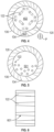
- the holes 122 can be counter-angled relative to the openings 134 of the outer swirler body 130 (see FIG. 4 ), the holes 122 can be non-uniformly distributed across a plane P of the plate body 121 (see FIG. 5 ) and one or more of the holes 122 can be tapered (see FIG. 6 ).
- the holes 122 can be counter-angled in a counter-clockwise direction 402. In this way, as hydrogen fuel passes through the holes 122, mixing of the clockwise flowing fluid and the counter-clockwise flow of hydrogen fuel can be increased. As shown in FIG.
- the holes 122 can be arranged in concentric rows around a centerline of the plate body 121 (see FIG. 1 ) but can also be non-uniformly distributed toward one or more sides.
- a greater number of holes 122 can be provided on the side of the plate body 121 closest to the outside of the bend to form a non-uniform distribution 501 at a location where most of the hydrogen fuel flow will be located as it completes its flow around the bend in the tubular element 110.
- one or more of the holes 122 can be tapered in either the upstream or downstream direction.
- the holes 122 can exhibit an inward tapering 601 toward the swirl area 133.
- a fuel nozzle 701 is provided and is generally similar to the fuel nozzle 101 with the primary difference being that the fuel nozzle 701 includes a radial fuel distributor 710 instead of the flat plate perforated fuel distributor 120 described above.
- the radial fuel distributor 701 may be envisioned.
- FIG. 7 describes a conical shape
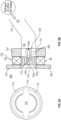
- FIGS. 8A and 8B and FIG. 9 describe a cylindrical shape.
- a variation of the conical distributor is also envisioned, where the shape of the distributor is defined according to the local fuel and air flows within the nozzle.
- the radial fuel distributor 710 is disposed along the tubular element 110 and includes a plate body 711 that defines one or more circumferential apertures 712.
- the one or more circumferential apertures 712 can be, but are not required to be, generally disposed at a periphery of the plate body 711 and are configured to allow hydrogen fuel to flow through to the swirl area 133.
- the one or more circumferential apertures 712 can point radially outwardly with decreasing distance to the swirl area 133 so that the circumferential apertures direct flow with an outward radial component (see FIG.
- each of the one or more circumferential apertures 712 can have a circumferential taper to thereby impart a swirling effect to the flow of the hydrogen fuel. It is to be understood that the thermal coating 160 and the embodiments of FIGS. 2 and 3 can be incorporated into the fuel nozzle 701.
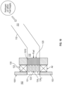
- a fuel nozzle 1001 is provided and is generally similar to the fuel nozzles 101 and 701 with the primary difference being that the fuel nozzle 1001 includes a foamed fuel distributor 1010 instead of the perforated fuel distributor 120 or the radial fuel distributor 710 described above.
- the foamed fuel distributor 1010 is disposed along the tubular element 110 and can be formed of at least one or more of metallic foam, a ceramic foam and a polymeric foam. It is to be understood that the thermal coating 160 and the embodiments of FIGS. 2 and 3 can be incorporated into the fuel nozzle 1001.
- the various embodiments described herein can be generally interchangeable with one another without undue experimentation.
- the counter-angled holes 122 of FIG. 4 can be non-uniformly distributed as shown in FIG. 5 .
Landscapes
- Engineering & Computer Science (AREA)
- Chemical & Material Sciences (AREA)
- Combustion & Propulsion (AREA)
- Mechanical Engineering (AREA)
- General Engineering & Computer Science (AREA)
- Nozzles (AREA)
- Spray-Type Burners (AREA)
Abstract
Description
- The present invention relates to fuel distribution and, in particular, to a perforated plate fuel distributor with a simplified swirler.
- In a gas turbine engine, fuel is combusted in a combustor to generate high-temperature and high-pressure working fluid that is expanded in a turbine to cause a rotor to rotate. Previously, the fuel has been liquid fuel and the components by which those fuels are transported to the combustor have been designed for compatibility with those fuels. Presently, however, there is an ongoing effort to replace liquid fuel with hydrogen as a fuel for turbine engines for use in flight applications and it has been found that the use of hydrogen requires certain changes be made to the components since they are not necessarily compatible with hydrogen.
- Previous attempts at retrofitting turbine engines for hydrogen have involved the use of a fuel distributor at an end of a fuel nozzle with jets that extend into the combustor. The fuel injectors and combustor components tended to experience thermal damage due to hydrogen having a higher flame speed than other types of fuels.
- A need therefore remains for a fuel nozzle in a turbine engine in flight applications that is compatible with hydrogen fuel.
- According to an aspect of the invention, a fuel nozzle for a turbine engine using hydrogen fuel is provided. The fuel nozzle includes a tubular element, a perforated fuel distributor disposed along the tubular element and comprising a plate body defining holes and a swirler element abuttable with an end wall of a combustor of the turbine engine. The swirler element includes an inner swirler body formed to define a swirl area receptive of hydrogen fuel from the tubular element via the holes and an outer swirler body disposed about the inner swirler body and formed to define openings through which fluid flows radially into the swirl area to mix with the hydrogen fuel prior to flowing into the combustor.
- In accordance with the previous aspect, the fuel nozzle further includes at least one of a valve at an upstream end of the tubular element to selectively block hydrogen fuel flow through the tubular element and an orifice at an upstream end of the tubular element to control hydrogen fuel flow through the tubular element.
- In accordance with any of the previous aspects or embodiments, at least one of the perforated fuel distributor and the swirler element includes at least one of metallic materials and ceramic materials.
- In accordance with any of the previous aspects or embodiments, the fuel nozzle further includes a thermal coating on at least the holes.
- In accordance with any of the previous aspects or embodiments, the holes are counter-angled relative to the openings of the outer swirler body.
- In accordance with any of the previous aspects or embodiments, the holes are non-uniformly distributed across a plane of the plate body.
- In accordance any of the previous aspects or embodiments, one or more of the holes are tapered.
- In accordance with any of the previous aspects or embodiments, the openings of the outer swirler body are at least one of vane openings and holes.
- According to another aspect of the invention, a fuel nozzle for a turbine engine using hydrogen fuel is provided. The fuel nozzle includes a tubular element, a radial fuel distributor disposed along the tubular element and comprising a plate body defining one or more circumferential apertures and a swirler element abuttable with an end wall of a combustor of the turbine engine. The swirler element includes an inner swirler body formed to define a swirl area receptive of hydrogen fuel from the tubular element via the one or more circumferential apertures and an outer swirler body disposed about the inner swirler body and formed to define openings through which fluid flows radially into the swirl area to mix with the hydrogen fuel prior to flowing into the combustor.
- In accordance with any of the previous aspects or embodiments, the fuel nozzle further includes at least one of a valve at an upstream end of the tubular element to selectively block hydrogen fuel flow through the tubular element and an orifice at an upstream end of the tubular element to control hydrogen fuel flow through the tubular element.
- In accordance with any of the previous aspects or embodiments, at least one of the radial fuel distributor and the swirler element includes at least one of metallic materials and ceramic materials.
- In accordance with any of the previous aspects or embodiments, the fuel nozzle further includes a thermal coating on at least the one or more circumferential apertures.
- In accordance with any of the previous aspects or embodiments, the one or more circumferential apertures are pointed radially outwardly.
- In accordance with any of the previous aspects or embodiments, the one or more circumferential apertures are pointed radially inwardly.
- In accordance with any of the previous aspects or embodiments, the openings of the outer swirler body are at least one of vane openings and holes.
- According to another aspect of the invention, a fuel nozzle for a turbine engine using hydrogen fuel is provided. The fuel nozzle includes a tubular element, a foamed fuel distributor disposed along the tubular element and a swirler element abuttable with an end wall of a combustor of the turbine engine. The swirler element includes an inner swirler body formed to define a swirl area receptive of hydrogen fuel from the tubular element through the foamed fuel distributor and an outer swirler body disposed about the inner swirler body and formed to define openings through which fluid flows radially into the swirl area to mix with the hydrogen fuel prior to flowing into the combustor.
- In accordance with any of the previous aspects or embodiments, the fuel nozzle further includes at least one of a valve at an upstream end of the tubular element to selectively block hydrogen fuel flow through the tubular element and an orifice at an upstream end of the tubular element to control hydrogen fuel flow through the tubular element.
- In accordance with any of the previous aspects or embodiments, the foamed fuel distributor includes at least one or more of metallic foam, a ceramic foam and a polymeric foam.
- In accordance with any of the previous aspects or embodiments, the fuel nozzle further includes a thermal coating on at least the foamed fuel distributor.
- In accordance with any of the previous aspects or embodiments, the openings of the outer swirler body are at least one of vane openings and holes.
- Additional features and advantages are realized through the techniques of the present disclosure. Other embodiments and aspects of the disclosure are described in detail herein and are considered a part of the claimed technical concept. For a better understanding of the disclosure with the advantages and the features, refer to the description and to the drawings.
- For a more complete understanding of this disclosure, reference is now made to the following brief description, taken in connection with the accompanying drawings and detailed description, wherein like reference numerals represent like parts:
-
FIG. 1 is a schematic side view of a fuel nozzle with a perforated fuel distributor for use with a turbine engine that is compatible with hydrogen as a fuel in accordance with embodiments; -
FIG. 2 is a schematic side view of a valve for the fuel nozzle ofFIG. 1 in accordance with embodiments; -
FIG. 3 is a schematic side view of an orifice for the fuel nozzle ofFIG. 1 in accordance with embodiments; -
FIG. 4 is a schematic axial view of a perforated fuel distributor with counter-angled holes of the fuel nozzle ofFIG. 1 in accordance with embodiments; -
FIG. 5 is a schematic axial view of a perforated fuel distributor with non-uniformly distributed holes of the fuel nozzle ofFIG. 1 in accordance with embodiments; -
FIG. 6 is a schematic side view of a perforated fuel distributor with tapered holes of the fuel nozzle ofFIG. 1 in accordance with embodiments; -
FIG. 7 is a schematic side view of a fuel nozzle with a radial fuel distributor for use with a turbine engine that is compatible with hydrogen as a fuel in accordance with embodiments; -
FIGS. 8A and 8B are schematic side and axial views of a radial fuel distributor with a radially outwardly pointing circumferential aperture of the fuel nozzle ofFIG. 7 in accordance with embodiments; -
FIG. 9 is a schematic axial view of a radial fuel distributor with a radially inwardly pointing circumferential aperture of the fuel nozzle ofFIG. 7 in accordance with embodiments; and -
FIG. 10 is a schematic side view of a fuel nozzle with a foamed metal fuel distributor for use with a turbine engine that is compatible with hydrogen as a fuel in accordance with embodiments. - As will be described below, a fuel nozzle is proposed for use with a turbine engine in flight applications and other applications that is compatible with hydrogen as a fuel. The fuel nozzle is flush with an end wall of a combustor and includes a tubular element leading to a perforated plate fuel distributor that distributes hydrogen fuel to a swirler area that abuts and is conformal with the end wall of the combustor. In the perforated plate fuel distributor, a hole distribution and flow area are provided to obtain mixing and a correct pressure drop and to arrest flashback. The swirler allows fluid to enter the swirler area through vanes or holes in a radial dimension with a circumferential component to mix with hydrogen fuel passing through the holes in the perforated plate fuel distributor prior to entering the combustor.
- In some cases, the perforated plate fuel distributor can be replaced by a rounded edge element or an element produced from metallic foam.
- In some other cases, the fuel nozzle can be turned on or off selectively to achieve certain performance characteristics.
- With reference to
FIG. 1 , afuel nozzle 101 is provided for a turbine engine that uses hydrogen fuel for combustion in acombustor 102 having anend wall 103. Thefuel nozzle 101 includes atubular element 110, aperforated fuel distributor 120 and aswirler element 130. Thetubular element 110 can be a duct defining a flow path having aninlet 111 and anoutlet 112 that connects to an interior of thecombustor 102 by way of an opening in theend wall 103. Theperforated fuel distributor 120 is disposed along thetubular element 110 and includes aplate body 121. Theplate body 121 is formed to defineholes 122. Theswirler element 130 is abuttable with theend wall 103. Theswirler element 130 includes aninner swirler body 131 and anouter swirler body 132. Theinner swirler body 131 is formed to define aswirl area 133. Theswirl areas 133 is receptive of hydrogen fuel from thetubular element 110 via theholes 122. Theouter swirler body 132 is disposed about theinner swirler body 131 and is formed to defineopenings 134 through which fluid flows radially into theswirl area 133 to mix with the hydrogen fuel prior to flowing into thecombustor 102. In accordance with embodiments, the fluid can be various types of combustible fluids including, but not limited to, air, oxygen and hydrogen and/or combinations thereof. - In accordance with embodiments and as shown in
FIG. 1 , theopenings 134 of theouter swirler body 132 can be provided as at least one ofvane openings 1341 that are generally elongate, and holes 1342 that are generally annular. - In accordance with embodiments, at least one of the
perforated fuel distributor 120 and theswirler element 130 includes at least one of metallic materials and ceramic materials (e.g., ceramic matrix composite materials). In the case of theperforated fuel distributor 120 being formed of metallic materials, thefuel nozzle 101 can further include athermal coating 160, such as thermal barrier coating (TBC), on at least the surfaces of theholes 122. The TBC can be designed to prevent or inhibit hydrogen embrittlement, for example, and can be applied using various processes such as chemical vapor deposition (CVD) or other similar processes. - With reference to
FIGS. 2 and 3 , thefuel nozzle 101 can further include at least one of a valve 140 (seeFIG. 2 ) and an orifice 150 (seeFIG. 3 ). In those embodiments which contain a valve, thevalve 140 and theorifice 150 may be combined. Theorifice 150 may be used to adjust the flow capacity of thefuel nozzle 101 to obtain the desired fuel distribution within the engine. As shown inFIG. 2 , thevalve 140 can be disposed at an upstream end (i.e., the inlet 111) of thetubular element 110 to selectively permit, adjust or block hydrogen fuel flow through thetubular element 110. As shown inFIG. 3 , theorifice 150 can be disposed at the upstream end (i.e., the inlet 111) of thetubular element 110 to control hydrogen fuel flow through thetubular element 110. At least theorifice 150 can be aimed to encourage hydrogen flow at a given angle through thetubular element 110, especially in a case in which thetubular element 110 is curved or bent as inFIG. 1 . For example, in a case in which thetubular element 110 is bent as inFIG. 1 , theorifice 150 can be aimed toward an outside of the bend to promote laminar hydrogen flow toward theperforated fuel distributor 120. - With continued reference to
FIG. 1 and with additional reference toFIGS. 4-6 , theholes 122 can be counter-angled relative to theopenings 134 of the outer swirler body 130 (seeFIG. 4 ), theholes 122 can be non-uniformly distributed across a plane P of the plate body 121 (seeFIG. 5 ) and one or more of theholes 122 can be tapered (seeFIG. 6 ). As shown inFIG. 4 , where theopenings 134 of theouter swirler body 130 are arranged in aclockwise pattern 401, theholes 122 can be counter-angled in acounter-clockwise direction 402. In this way, as hydrogen fuel passes through theholes 122, mixing of the clockwise flowing fluid and the counter-clockwise flow of hydrogen fuel can be increased. As shown inFIG. 5 , theholes 122 can be arranged in concentric rows around a centerline of the plate body 121 (seeFIG. 1 ) but can also be non-uniformly distributed toward one or more sides. For example, in the case of thetubular element 110 being bent as inFIG. 1 , a greater number ofholes 122 can be provided on the side of theplate body 121 closest to the outside of the bend to form anon-uniform distribution 501 at a location where most of the hydrogen fuel flow will be located as it completes its flow around the bend in thetubular element 110. As shown inFIG. 6 , one or more of theholes 122 can be tapered in either the upstream or downstream direction. For example, to maintain hydrogen fuel flow velocity through theholes 122, theholes 122 can exhibit aninward tapering 601 toward theswirl area 133. - With reference to
FIGS. 7-9 , afuel nozzle 701 is provided and is generally similar to thefuel nozzle 101 with the primary difference being that thefuel nozzle 701 includes aradial fuel distributor 710 instead of the flat plateperforated fuel distributor 120 described above. With this in mind, different shapes of theradial fuel distributor 701 may be envisioned. For example,FIG. 7 describes a conical shape, whileFIGS. 8A and 8B andFIG. 9 describe a cylindrical shape. A variation of the conical distributor is also envisioned, where the shape of the distributor is defined according to the local fuel and air flows within the nozzle. - As shown in
FIG. 7 , theradial fuel distributor 710 is disposed along thetubular element 110 and includes aplate body 711 that defines one or morecircumferential apertures 712. The one or morecircumferential apertures 712 can be, but are not required to be, generally disposed at a periphery of theplate body 711 and are configured to allow hydrogen fuel to flow through to theswirl area 133. As shown inFIGS. 8A and 8B andFIG. 9 , the one or morecircumferential apertures 712 can point radially outwardly with decreasing distance to theswirl area 133 so that the circumferential apertures direct flow with an outward radial component (seeFIG. 8 ) or radially inwardly with decreasing distance to theswirl area 133 so that the circumferential apertures direct flow with an inward radial component (seeFIG. 9 ). Although not shown inFIGS. 7-9 , each of the one or morecircumferential apertures 712 can have a circumferential taper to thereby impart a swirling effect to the flow of the hydrogen fuel. It is to be understood that thethermal coating 160 and the embodiments ofFIGS. 2 and 3 can be incorporated into thefuel nozzle 701. - With reference to
FIG. 10 , afuel nozzle 1001 is provided and is generally similar to thefuel nozzles fuel nozzle 1001 includes a foamedfuel distributor 1010 instead of theperforated fuel distributor 120 or theradial fuel distributor 710 described above. The foamedfuel distributor 1010 is disposed along thetubular element 110 and can be formed of at least one or more of metallic foam, a ceramic foam and a polymeric foam. It is to be understood that thethermal coating 160 and the embodiments ofFIGS. 2 and 3 can be incorporated into thefuel nozzle 1001. - It is to be understood that the various embodiments described herein can be generally interchangeable with one another without undue experimentation. For example, the
counter-angled holes 122 ofFIG. 4 can be non-uniformly distributed as shown inFIG. 5 . - Technical effects and benefits of the present disclosure are the provision of a fuel nozzle for use with a turbine engine in flight applications or other applications that is compatible with hydrogen fuel. A turbine engine can be retrofit with the fuel nozzle with a relatively minimal amount of service and maintenance effort.
- The corresponding structures, materials, acts, and equivalents of all means or step-plus function elements in the claims below are intended to include any structure, material, or act for performing the function in combination with other claimed elements as specifically claimed. The description of the present disclosure has been presented for purposes of illustration and description, but is not intended to be exhaustive or limited to the technical concepts in the form disclosed. Many modifications and variations will be apparent to those of ordinary skill in the art without departing from the scope and spirit of the disclosure. The embodiments were chosen and described in order to best explain the principles of the disclosure and the practical application, and to enable others of ordinary skill in the art to understand the disclosure for various embodiments with various modifications as are suited to the particular use contemplated.
- While the preferred embodiments to the disclosure have been described, it will be understood that those skilled in the art, both now and in the future, may make various improvements and enhancements which fall within the scope of the claims which follow. These claims should be construed to maintain the proper protection for the disclosure first described.
Claims (15)
- A fuel nozzle (101) for a turbine engine using hydrogen fuel, the fuel nozzle (101) comprising:a tubular element (110);a perforated fuel distributor (120) disposed along the tubular element (110) and comprising a plate body (121) defining holes (122); anda swirler element (130) abuttable with an end wall (103) of a combustor (102) of the turbine engine and comprising:an inner swirler body (131) formed to define a swirl area (133) receptive of hydrogen fuel from the tubular element (110) via the holes (122); andan outer swirler body (132) disposed about the inner swirler body (131) and formed to define openings (134) through which fluid flows radially into the swirl area (133) to mix with the hydrogen fuel prior to flowing into the combustor (102).
- The fuel nozzle (101) according to claim 1, further comprising:a valve (140) at an upstream end (111) of the tubular element (110) to selectively block hydrogen fuel flow through the tubular element (110); and/oran orifice (150) at an upstream end (111) of the tubular element (110) to control hydrogen fuel flow through the tubular element (110).
- The fuel nozzle (101) according to claim 1 or 2, wherein the perforated fuel distributor (120) and/or the swirler element (130) comprises metallic materials and/or ceramic materials.
- The fuel nozzle (101) according to claim 1, 2 or 3, further comprising a thermal coating (160) on at least the holes (122).
- The fuel nozzle (101) according to any preceding claim, wherein the holes (122) are counter-angled relative to the openings (134) of the outer swirler body (132).
- The fuel nozzle (101) according to any preceding claim, wherein the holes (122) are non-uniformly distributed across a plane of the plate body (121).
- The fuel nozzle (101) according to any preceding claim, wherein one or more of the holes (122) are tapered.
- The fuel nozzle (101) according to any preceding claim, wherein the openings (134) of the outer swirler body (132) are vane openings and/or holes.
- A fuel nozzle (701) for a turbine engine using hydrogen fuel, the fuel nozzle (701) comprising:a tubular element (110);a radial fuel distributor (710) disposed along the tubular element (110) and comprising a plate body (711) defining one or more circumferential apertures (712); anda swirler element (130) abuttable with an end wall (103) of a combustor (102) of the turbine engine and comprising:an inner swirler body (131) formed to define a swirl area (133) receptive of hydrogen fuel from the tubular element (110) via the one or more circumferential apertures (712); andan outer swirler body (132) disposed about the inner swirler body (131) and formed to define openings (134) through which fluid flows radially into the swirl area (133) to mix with the hydrogen fuel prior to flowing into the combustor (102), optionally wherein:the fuel nozzle (701) further comprises:a valve (140) at an upstream end (111) of the tubular element (110) to selectively block hydrogen fuel flow through the tubular element (110); and/oran orifice (150) at an upstream end (111) of the tubular element (110) to control hydrogen fuel flow through the tubular element (110); and/orthe openings (134) of the outer swirler body (132) are vane openings and/or holes.
- The fuel nozzle (701) according to claim 9, wherein the radial fuel distributor (710) and/or the swirler element (130) comprises metallic materials and/or ceramic materials.
- The fuel nozzle (701) according to claim 9 or 10, further comprising a thermal coating (160) on at least the one or more circumferential apertures (712).
- The fuel nozzle (701) according to any of claims 9 to 11, wherein:the one or more circumferential apertures (712) are pointed radially outwardly; orthe one or more circumferential apertures (712) are pointed radially inwardly.
- A fuel nozzle (1001) for a turbine engine using hydrogen fuel, the fuel nozzle (1001) comprising:a tubular element (110);a foamed fuel distributor (1010) disposed along the tubular element (110); anda swirler element (130) abuttable with an end wall (103) of a combustor (102) of the turbine engine and comprising:an inner swirler body (131) formed to define a swirl area (133) receptive of hydrogen fuel from the tubular element (110) through the foamed fuel distributor (1010); andan outer swirler body (132) disposed about the inner swirler body (131) and formed to define openings (134) through which fluid flows radially into the swirl area (133) to mix with the hydrogen fuel prior to flowing into the combustor (102), optionally wherein:the fuel nozzle (1001) further comprises:a valve (140) at an upstream end of the tubular element (110) to selectively block hydrogen fuel flow through the tubular element (110); and/oran orifice (150) at an upstream end (111) of the tubular element (110) to control hydrogen fuel flow through the tubular element (110),the openings (134) of the outer swirler body (132) are vane openings and/or holes.
- The fuel nozzle (1001) according to claim 13, wherein the foamed fuel distributor (1010) comprises a metallic foam, a ceramic foam and/or a polymeric foam.
- The fuel nozzle (1001) according to claim 13 or 14, further comprising a thermal coating (160) on at least the foamed fuel distributor (1010).
Applications Claiming Priority (1)
| Application Number | Priority Date | Filing Date | Title |
|---|---|---|---|
| US18/165,813 US20240263792A1 (en) | 2023-02-07 | 2023-02-07 | Perforated plate fuel distributor with simiplified swirler |
Publications (1)
| Publication Number | Publication Date |
|---|---|
| EP4414609A1 true EP4414609A1 (en) | 2024-08-14 |
Family
ID=89854374
Family Applications (1)
| Application Number | Title | Priority Date | Filing Date |
|---|---|---|---|
| EP24156411.1A Pending EP4414609A1 (en) | 2023-02-07 | 2024-02-07 | Perforated plate fuel distributor with simplified swirler |
Country Status (3)
| Country | Link |
|---|---|
| US (2) | US20240263792A1 (en) |
| EP (1) | EP4414609A1 (en) |
| CA (1) | CA3228339A1 (en) |
Families Citing this family (1)
| Publication number | Priority date | Publication date | Assignee | Title |
|---|---|---|---|---|
| CA3281692A1 (en) * | 2024-10-28 | 2026-05-13 | Pratt & Whitney Canada Corp. | Hydrogen nozzle with multiple flow circuits and flow directing swirler |
Citations (9)
| Publication number | Priority date | Publication date | Assignee | Title |
|---|---|---|---|---|
| EP0673490B1 (en) * | 1993-10-19 | 1997-12-29 | European Gas Turbines Limited | Fuel injector |
| US6684640B2 (en) * | 2000-10-23 | 2004-02-03 | Alstom Power N.V. | Gas turbine engine combustion system |
| US7065972B2 (en) * | 2004-05-21 | 2006-06-27 | Honeywell International, Inc. | Fuel-air mixing apparatus for reducing gas turbine combustor exhaust emissions |
| US20100126176A1 (en) * | 2008-11-26 | 2010-05-27 | Ik Soo Kim | Dual swirler |
| US20120186256A1 (en) * | 2011-01-26 | 2012-07-26 | United Technologies Corporation | Mixer assembly for a gas turbine engine |
| US20150033752A1 (en) * | 2012-03-13 | 2015-02-05 | Siemens Aktiengesellschaft | Gas turbine combustion system and method of flame stabilization in such a system |
| US20170211807A1 (en) * | 2014-04-07 | 2017-07-27 | Siemens Aktiengesellschaft | A burner tip and a burner for a gas turbine |
| US20190162414A1 (en) * | 2016-06-30 | 2019-05-30 | Kawasaki Jukogyo Kabushiki Kaisha | Gas turbine combustor |
| GB2593123A (en) * | 2019-06-25 | 2021-09-22 | Siemens Ag | Combustor for a gas turbine |
-
2023
- 2023-02-07 US US18/165,813 patent/US20240263792A1/en not_active Abandoned
-
2024
- 2024-02-06 CA CA3228339A patent/CA3228339A1/en active Pending
- 2024-02-07 EP EP24156411.1A patent/EP4414609A1/en active Pending
-
2025
- 2025-10-21 US US19/365,061 patent/US20260043546A1/en active Pending
Patent Citations (9)
| Publication number | Priority date | Publication date | Assignee | Title |
|---|---|---|---|---|
| EP0673490B1 (en) * | 1993-10-19 | 1997-12-29 | European Gas Turbines Limited | Fuel injector |
| US6684640B2 (en) * | 2000-10-23 | 2004-02-03 | Alstom Power N.V. | Gas turbine engine combustion system |
| US7065972B2 (en) * | 2004-05-21 | 2006-06-27 | Honeywell International, Inc. | Fuel-air mixing apparatus for reducing gas turbine combustor exhaust emissions |
| US20100126176A1 (en) * | 2008-11-26 | 2010-05-27 | Ik Soo Kim | Dual swirler |
| US20120186256A1 (en) * | 2011-01-26 | 2012-07-26 | United Technologies Corporation | Mixer assembly for a gas turbine engine |
| US20150033752A1 (en) * | 2012-03-13 | 2015-02-05 | Siemens Aktiengesellschaft | Gas turbine combustion system and method of flame stabilization in such a system |
| US20170211807A1 (en) * | 2014-04-07 | 2017-07-27 | Siemens Aktiengesellschaft | A burner tip and a burner for a gas turbine |
| US20190162414A1 (en) * | 2016-06-30 | 2019-05-30 | Kawasaki Jukogyo Kabushiki Kaisha | Gas turbine combustor |
| GB2593123A (en) * | 2019-06-25 | 2021-09-22 | Siemens Ag | Combustor for a gas turbine |
Also Published As
| Publication number | Publication date |
|---|---|
| CA3228339A1 (en) | 2025-04-10 |
| US20240263792A1 (en) | 2024-08-08 |
| US20260043546A1 (en) | 2026-02-12 |
Similar Documents
| Publication | Publication Date | Title |
|---|---|---|
| US11655979B2 (en) | Airblast fuel nozzle | |
| US11002190B2 (en) | Segmented annular combustion system | |
| US10184665B2 (en) | Prefilming air blast (PAB) pilot having annular splitter surrounding a pilot fuel injector | |
| EP2375163B1 (en) | Segmented annular ring-manifold quaternary fuel distributor | |
| US20120125004A1 (en) | Combustor premixer | |
| US9927126B2 (en) | Prefilming air blast (PAB) pilot for low emissions combustors | |
| US20260043546A1 (en) | Perforated plate fuel distributor with simiplified swirler | |
| US9939157B2 (en) | Hybrid air blast fuel nozzle | |
| EP2218966B1 (en) | Fuel injection for gas turbine combustors | |
| US20140291418A1 (en) | Multi-circuit airblast fuel nozzle | |
| US20110271682A1 (en) | Device for injecting a mixture of air and fuel into a turbomachine combustion chamber | |
| EP4202302B1 (en) | Fuel nozzle and swirler | |
| US20170268786A1 (en) | Axially staged fuel injector assembly | |
| CN102261673A (en) | Hybrid prefilming airblast, prevaporizing, lean-premixing dual-fuel nozzle for gas turbine combustor | |
| HUP0203137A2 (en) | Atomizing burner | |
| US11680527B2 (en) | Nozzles with internal manifolding | |
| US20250383090A1 (en) | Injector assembly for an engine, and aircraft | |
| US20150020501A1 (en) | An annular combustion chamber in a turbine engine | |
| US20260063299A1 (en) | Burner for combustor with ammonia injection downstream of swozzle assembly and related method |
Legal Events
| Date | Code | Title | Description |
|---|---|---|---|
| PUAI | Public reference made under article 153(3) epc to a published international application that has entered the european phase |
Free format text: ORIGINAL CODE: 0009012 |
|
| STAA | Information on the status of an ep patent application or granted ep patent |
Free format text: STATUS: THE APPLICATION HAS BEEN PUBLISHED |
|
| AK | Designated contracting states |
Kind code of ref document: A1 Designated state(s): AL AT BE BG CH CY CZ DE DK EE ES FI FR GB GR HR HU IE IS IT LI LT LU LV MC ME MK MT NL NO PL PT RO RS SE SI SK SM TR |
|
| STAA | Information on the status of an ep patent application or granted ep patent |
Free format text: STATUS: REQUEST FOR EXAMINATION WAS MADE |
|
| 17P | Request for examination filed |
Effective date: 20250213 |
|
| GRAP | Despatch of communication of intention to grant a patent |
Free format text: ORIGINAL CODE: EPIDOSNIGR1 |
|
| STAA | Information on the status of an ep patent application or granted ep patent |
Free format text: STATUS: GRANT OF PATENT IS INTENDED |