EP4414608A2 - Turbine engine fuel injector with oxygen circuit - Google Patents
Turbine engine fuel injector with oxygen circuit Download PDFInfo
- Publication number
- EP4414608A2 EP4414608A2 EP24157190.0A EP24157190A EP4414608A2 EP 4414608 A2 EP4414608 A2 EP 4414608A2 EP 24157190 A EP24157190 A EP 24157190A EP 4414608 A2 EP4414608 A2 EP 4414608A2
- Authority
- EP
- European Patent Office
- Prior art keywords
- gas
- fuel
- case wall
- splash plate
- passage
- Prior art date
- Legal status (The legal status is an assumption and is not a legal conclusion. Google has not performed a legal analysis and makes no representation as to the accuracy of the status listed.)
- Pending
Links
Images



Classifications
-
- F—MECHANICAL ENGINEERING; LIGHTING; HEATING; WEAPONS; BLASTING
- F02—COMBUSTION ENGINES; HOT-GAS OR COMBUSTION-PRODUCT ENGINE PLANTS
- F02C—GAS-TURBINE PLANTS; AIR INTAKES FOR JET-PROPULSION PLANTS; CONTROLLING FUEL SUPPLY IN AIR-BREATHING JET-PROPULSION PLANTS
- F02C7/00—Features, components parts, details or accessories, not provided for in, or of interest apart form groups F02C1/00 - F02C6/00; Air intakes for jet-propulsion plants
- F02C7/22—Fuel supply systems
-
- F—MECHANICAL ENGINEERING; LIGHTING; HEATING; WEAPONS; BLASTING
- F23—COMBUSTION APPARATUS; COMBUSTION PROCESSES
- F23R—GENERATING COMBUSTION PRODUCTS OF HIGH PRESSURE OR HIGH VELOCITY, e.g. GAS-TURBINE COMBUSTION CHAMBERS
- F23R3/00—Continuous combustion chambers using liquid or gaseous fuel
- F23R3/02—Continuous combustion chambers using liquid or gaseous fuel characterised by the air-flow or gas-flow configuration
- F23R3/04—Air inlet arrangements
- F23R3/06—Arrangement of apertures along the flame tube
-
- F—MECHANICAL ENGINEERING; LIGHTING; HEATING; WEAPONS; BLASTING
- F23—COMBUSTION APPARATUS; COMBUSTION PROCESSES
- F23R—GENERATING COMBUSTION PRODUCTS OF HIGH PRESSURE OR HIGH VELOCITY, e.g. GAS-TURBINE COMBUSTION CHAMBERS
- F23R3/00—Continuous combustion chambers using liquid or gaseous fuel
- F23R3/28—Continuous combustion chambers using liquid or gaseous fuel characterised by the fuel supply
-
- F—MECHANICAL ENGINEERING; LIGHTING; HEATING; WEAPONS; BLASTING
- F23—COMBUSTION APPARATUS; COMBUSTION PROCESSES
- F23R—GENERATING COMBUSTION PRODUCTS OF HIGH PRESSURE OR HIGH VELOCITY, e.g. GAS-TURBINE COMBUSTION CHAMBERS
- F23R3/00—Continuous combustion chambers using liquid or gaseous fuel
- F23R3/28—Continuous combustion chambers using liquid or gaseous fuel characterised by the fuel supply
- F23R3/283—Attaching or cooling of fuel injecting means including supports for fuel injectors, stems, or lances
-
- F—MECHANICAL ENGINEERING; LIGHTING; HEATING; WEAPONS; BLASTING
- F23—COMBUSTION APPARATUS; COMBUSTION PROCESSES
- F23R—GENERATING COMBUSTION PRODUCTS OF HIGH PRESSURE OR HIGH VELOCITY, e.g. GAS-TURBINE COMBUSTION CHAMBERS
- F23R3/00—Continuous combustion chambers using liquid or gaseous fuel
- F23R3/28—Continuous combustion chambers using liquid or gaseous fuel characterised by the fuel supply
- F23R3/286—Continuous combustion chambers using liquid or gaseous fuel characterised by the fuel supply having fuel-air premixing devices
-
- F—MECHANICAL ENGINEERING; LIGHTING; HEATING; WEAPONS; BLASTING
- F23—COMBUSTION APPARATUS; COMBUSTION PROCESSES
- F23D—BURNERS
- F23D2900/00—Special features of, or arrangements for burners using fluid fuels or solid fuels suspended in a carrier gas
- F23D2900/11001—Impinging-jet injectors or jet impinging on a surface
-
- F—MECHANICAL ENGINEERING; LIGHTING; HEATING; WEAPONS; BLASTING
- F23—COMBUSTION APPARATUS; COMBUSTION PROCESSES
- F23D—BURNERS
- F23D2900/00—Special features of, or arrangements for burners using fluid fuels or solid fuels suspended in a carrier gas
- F23D2900/11101—Pulverising gas flow impinging on fuel from pre-filming surface, e.g. lip atomizers
Definitions
- This disclosure relates generally to a turbine engine and, more particularly, to a fuel injector for the turbine engine.
- a combustor section in a modern turbine engine includes one or more fuel injectors.
- Each fuel injector is operable to inject fuel for combustion within a combustion chamber.
- Various types and configurations of fuel injectors are known in the art. While these known fuel injectors have various benefits, there is still room in the art for improvement. There is a need in the art, for example, for a fuel injector which can facilitate turbine engine start up a relatively high altitude.
- a system for an aerial vehicle.
- This system includes a splash plate, a fuel nozzle and a gas circuit.
- the splash plate includes a splash plate surface.
- the fuel nozzle includes a nozzle orifice.
- the fuel nozzle is configured to direct fuel out of the nozzle orifice to impinge against the splash plate surface.
- the gas circuit includes a gas passage and a gas outlet. At least a portion of the gas passage is formed by and embedded within the splash plate. The gas passage extends through the splash plate to the gas outlet.
- this system includes a case wall, a fuel injector, a fuel circuit and a gas circuit.
- the case wall extends axially along and circumferentially about an axial centerline.
- the fuel injector is connected to and radially inboard of the case wall.
- the fuel circuit is configured to deliver fuel to the fuel injector.
- the fuel circuit includes a fuel supply passage integrated with the case wall.
- the fuel supply passage extends along the case wall circumferentially about the axial centerline.
- the gas circuit is configured to deliver oxygen gas to the fuel injector.
- the gas circuit includes a gas supply passage embedded within the case wall.
- the gas supply passage extends within the case wall circumferentially about the axial centerline.
- an aerial vehicle includes an airframe body, a turbine engine, a gas circuit and an oxygen gas source.
- the airframe body includes an access port.
- the turbine engine is housed within the airframe body.
- the turbine engine includes a case wall and a fuel injector.
- the case wall includes a boss radially inboard of and overlapped by the access port. At least the airframe body and the case wall are configured together in a monolithic body.
- the fuel injector is radially inboard of the case wall.
- the gas circuit is configured to deliver oxygen gas to the fuel injector.
- the gas circuit includes a gas line fitting and a gas supply passage embedded within the case wall.
- the gas supply passage extends within the case wall circumferentially about an axial centerline of the turbine engine.
- the gas line fitting is bonded to the boss.
- the oxygen gas source is fluidly coupled to the gas supply passage through the gas line fitting.
- the fuel injector may include a splash plate and a fuel nozzle.
- the fuel nozzle may include a nozzle orifice fluidly coupled with and downstream of the fuel supply passage.
- the fuel nozzle may be configured to direct the fuel out of the nozzle orifice to impinge against the splash plate.
- the gas circuit may also include a gas passage and a gas orifice in a surface of the splash plate.
- the gas passage may be fluidly coupled with and downstream of the gas supply passage.
- the gas passage may extend through the splash plate to the gas orifice.
- the system may also include a second fuel injector connected to and radially inboard of the case wall.
- the fuel circuit may also be configured to deliver the fuel to the second fuel injector.
- the gas circuit may also be configured to deliver the oxygen gas to the second fuel injector.
- the system may also include a monolithic body, and the monolithic body may include the case wall and the fuel injector.
- the system may also include a gas source fluidly coupled with the gas circuit.
- the gas circuit may be configured to receive gas from the gas source.
- the gas passage may be configured to direct the gas to the gas outlet.
- the gas source may be configured as or otherwise include a gas reservoir.
- the gas received by the gas circuit from the gas source may be (e.g., consist of) oxygen gas.
- the gas outlet may be located remote from the splash plate surface.
- the splash plate may also include a second surface.
- the gas outlet may be disposed in the second surface.
- the second surface may be adjacent the splash plate surface.
- the gas circuit may be configured to direct gas out of the gas outlet downstream of the splash plate surface.
- the downstream direction may be defined relative to a direction of airflow through the aerial vehicle, where the aerial vehicle may be a turbine engine.
- the gas circuit may be configured to direct gas out of the gas outlet along a trajectory angularly offset from the splash plate surface and away from the fuel impinging against the splash plate surface.
- the system may also include an air tube including (or defining) an air passage.
- the fuel nozzle may project into the air passage.
- the splash plate may be arranged at least partially within the air passage such that the splash plate is configured to direct at least some of the fuel against an inner sidewall surface of the air tube.
- the gas circuit may be configured to direct gas out of the gas outlet into the air passage along a trajectory that is parallel with a centerline of the air tube or angularly offset from (e.g. not parallel to) the centerline of the air tube by less than ten degrees.
- the system may also include a combustor wall at least partially forming a combustion chamber.
- the air tube may be connected to the combustor wall and may project into the combustion chamber.
- the system may also include a case wall and a support member.
- the fuel nozzle may be connected to and project inward from the case wall.
- the support member may be connected to and extend between the case wall and the fuel nozzle.
- the splash plate may be connected to the support member.
- the support member may be configured as or otherwise include a strut.
- Another portion of the gas passage (the another portion being a different, or second, portion to the at least one portion of the gas passage defined above) may be formed by and embedded within the support member.
- the gas passage may extend though the support member from the case wall to the splash plate.
- the system may also include a case wall extending axially along and circumferentially about an axial centerline.
- the gas circuit may also include a supply passage formed by and embedded within the case wall.
- the supply passage may extend circumferentially about the axial centerline.
- the gas passage may be fluidly coupled with and downstream of the supply passage.
- the case wall may include a boss.
- the gas circuit may also include a gas line fitting bonded to the boss.
- the supply passage may be fluidly coupled with and downstream of the gas line fitting.
- the system may also include an airframe body and a turbine engine.
- the airframe body includes an access port.
- the turbine engine may be housed within the airframe body.
- the turbine engine may include the splash plate, the fuel nozzle and the case wall.
- the access port may be radially outboard of and overlap the boss and the gas line fitting.
- an aerial vehicle comprising the system of any of the above, or there may be a turbine engine comprising the system of any of the above, or there may be a aerial vehicle comprising a turbine engine comprising the system of any of the above.
- the aerial vehicle and/or turbine engine may have a central axis defining an or the axial centerline.
- the central axis may also define a radial direction, and any reference to a ⁇ radially outboard' and ⁇ radially inboard' above may be defined relative to this radial direction. Any reference to a 'downstream' direction may be defined in relation to a direction of airflow through the aerial vehicle and/or turbine engine.
- the axial centerline of the case wall as defined above may be in line with the axial centerline of the aerial vehicle and/or turbine engine.
- the present disclosure may include any one or more of the individual features disclosed above and/or below alone or in any combination thereof.
- FIG. 1 illustrates a gas turbine engine 20 for an aerial vehicle such as, but not limited to, an unmanned aerial vehicle (UAV), a drone or any other manned or unmanned aircraft or self-propelled projectile.
- the turbine engine 20 of FIG. 1 is configured as a single spool, radial-flow turbojet gas turbine engine. This turbine engine 20 is configured for propelling the aerial vehicle during flight.
- the present disclosure is not limited to such an exemplary turbojet gas turbine engine configuration nor to a vehicle propulsion system application.
- the turbine engine 20 may alternatively be configured as an auxiliary power unit (APU) for the aerial vehicle.
- APU auxiliary power unit
- the turbine engine 20 of FIG. 1 extends axially along an axial centerline 22 between a forward, upstream airflow inlet 24 into the turbine engine 20 and an aft, downstream exhaust 26 out of the turbine engine 20.
- This axial centerline 22 may be a centerline axis of the turbine engine 20.
- the axial centerline 22 may also or alternatively be a rotational axis for one or more components within the turbine engine 20.
- the turbine engine 20 includes a core flowpath 28, an inlet section 30, a (e.g., radial flow) compressor section 31, a (e.g., reverse flow) combustor section 32, a (e.g., radial flow) turbine section 33 and an exhaust section 34.
- the turbine engine 20 also includes a static engine structure 36 housing and/or forming one or more or all of the engine sections 30-34.
- the core flowpath 28 extends within the turbine engine 20 between the engine inlet 24 and the engine exhaust 26. More particularly, the core flowpath 28 extends sequentially through the inlet section 30, the compressor section 31, the combustor section 32, the turbine section 33 and the exhaust section 34 from the engine inlet 24 to the engine exhaust 26.
- the compressor section 31 includes a bladed compressor rotor 38.
- the turbine section 33 includes a bladed turbine rotor 40.
- Each of these engine rotors 38, 40 includes a plurality of rotor blades arranged circumferentially around and connected to at least one respective rotor disk and/or hub.
- the rotor blades may be formed integral with or mechanically fastened, welded, brazed, adhered and/or otherwise attached to the respective rotor disk(s) and/or hub(s).
- the compressor rotor 38 may be configured as a radial flow compressor rotor.
- the turbine rotor 40 may be configured as a radial flow turbine rotor.
- the compressor rotor 38 is connected to the turbine rotor 40 through an engine shaft 42.
- This engine shaft 42 is rotatably supported by the static engine structure 36 through a plurality of bearings 44; e.g., rolling element bearings, journal bearings, etc.
- the combustor section 32 includes an annular combustor 46 with an annular combustion chamber 48.
- the combustor 46 of FIG. 1 is configured as a reverse flow combustor.
- Air tubes 50A and 50B (generally referred to as "50") (e.g., dilution chutes, flow tubes, etc.) into the combustion chamber 48, for example, may be arranged at (e.g., on, adjacent or proximate) and/or towards an aft bulkhead wall 52 of the combustor 46.
- An outlet from the combustor 46 may be arranged axially aft of an inlet to the turbine section 33.
- the combustor 46 may also be arranged radially outboard of and/or axially overlap at least a portion (e.g., aft portion) of the turbine section 33.
- the core flowpath 28 of FIG. 1 reverses direction (e.g., from a forward-to-aft direction to an aft-to-forward direction) a first time as the core flowpath 28 extends from a diffuser plenum 54 surrounding the combustor 46 into the combustion chamber 48.
- the core flowpath 28 of FIG. 1 then reverses its direction (e.g., from the aft-to-forward direction to the forward-to-aft direction) a second time as the core flowpath 28 extends from the combustion chamber 48 into the turbine section 33.
- the inlet section 30 directs this air from the engine inlet 24 into the core flowpath 28 and the compressor section 31.
- the air within the core flowpath 28 may be referred to as core air.
- This core air is compressed by the compressor rotor 38 and directed through a diffuser 56 and its diffuser plenum 54 into the combustion chamber 48.
- Fuel is injected via one or more fuel injectors 58 and mixed with the compressed core air to provide a fuel-air mixture.
- This fuel-air mixture is ignited within the combustion chamber 48, and combustion products thereof flow through the turbine section 33 and cause the turbine rotor 40 to rotate.
- the rotation of the turbine rotor 40 drives rotation of the compressor rotor 38 and, thus, compression of the air received from the engine inlet 24.
- the exhaust section 34 receives the combustion products from the turbine section 33.
- the exhaust section 34 directs the received combustion products out of the turbine engine 20 to provide, for example, forward engine thrust.
- FIG. 2 illustrates a portion of a system 60 for the aerial vehicle.
- This vehicle system 60 includes at least a portion of the static engine structure 36 within / forming the combustor section 32.
- the static engine structure 36 includes the combustor 46 and a case wall 62 surrounding the combustor 46.
- the vehicle system 60 also includes a fuel and gas injection system 64.
- the combustor 46 of FIG. 2 includes an outer combustor wall 66, an inner combustor wall 68 and the bulkhead wall 52.
- the outer combustor wall 66 extends axially along the axial centerline 22 between and may be connected to an outer platform of a turbine nozzle 70 (see FIG. 1 ) and the bulkhead wall 52.
- the outer combustor wall 66 extends circumferentially about (e.g., circumscribes), axially overlaps and is spaced radially outward from the inner combustor wall 68.
- the inner combustor wall 68 extends axially between an inner platform of the turbine nozzle 70 (see FIG.
- the inner combustor wall 68 extends circumferentially about (e.g., circumscribes), axially overlaps and is spaced radially outward from a turbine case 72 (see also FIG. 1 ).
- the bulkhead wall 52 extends radially between the outer combustor wall 66 and the inner combustor wall 68, at aft ends of the combustor walls 66 and 68. With this arrangement, the combustor walls 52, 66 and 68 collectively form peripheral boundaries of the combustion chamber 48 within the combustor 46.
- the combustor 46 of FIG. 2 also includes one or more sets of the air tubes 50.
- the air tubes 50 in each set are arranged circumferentially about the axial centerline 22 in a circular array.
- each of the air tubes 50 is connected to (e.g., formed integral with or otherwise attached to) the outer combustor wall 66.
- Each of the air tubes 50 projects radially inward from the outer combustor wall 66 partially into the combustion chamber 48 to a distal inner end of the respective air tube 50.
- Each air tube 50 has an internal air passage 74; e.g., an inner bore of the respective air tube 50.
- This air passage 74 extends longitudinally along a longitudinal centerline 76 of the respective air tube 50 and/or the respective air passage 74 through the air tube 50. More particularly, the air passage 74 extends longitudinally from an inlet 78 into the air passage 74 to an outlet 80 from the air passage 74.
- the air passage inlet 78 of FIG. 2 is disposed at an outer end of the respective air tube 50.
- the air passage outlet 80 of FIG. 2 is disposed at the inner end of the respective air tube 50.
- each air tube 50 and its air passage 74 fluidly couples the diffuser plenum 54 outside of the combustor 46 and radially outboard of the outer combustor wall 66 with the combustion chamber 48 inside of the combustor 46 and radially inboard of the outer combustor wall 66.
- each longitudinal centerline 76 When viewed in a first reference plane parallel with (e.g., that includes) the axial centerline 22 (e.g., plane of FIG. 2 ), each longitudinal centerline 76 may be perpendicular to the axial centerline 22, or angularly offset from the axial centerline 22 by less than ten degrees (10°) or five degrees (5°). When viewed in a second reference plane perpendicular to the axial centerline 22 (e.g., plane of FIG. 3 ), each longitudinal centerline 76 may be angularly offset from a reference line 82 by an angle 84.
- the reference line 82 may be a ray projecting radially out from the axial centerline 22 to (e.g., a center of) the air passage inlet 78 associated with the respective longitudinal centerline 76.
- the angle 84 may be a (e.g., non-zero) acute angle between, for example, ten degrees (10°) and forty-five degrees (45°).
- the present disclosure is not limited to the foregoing exemplary air tube / air passage configurations.
- the air tubes 50 may be alternatively arranged to tailor combustion dynamics within the combustion chamber 48.
- the case wall 62 may be configured as an outer case of the diffuser 56; e.g., an outer diffuser case.
- the case wall 62 of FIG. 2 is configured to at least partially house the combustor 46 within the combustor section 32.
- the case wall 62 of FIG. 2 in particular, includes a sidewall section 86 and an endwall section 88.
- the case wall 62 and its sidewall section 86 extend circumferentially about (e.g., circumscribe), axially overlap and are spaced radially outward from the combustor 46 and its outer combustor wall 66.
- the case wall 62 may thereby form an outer peripheral boundary of the core flowpath 28 and the diffuser plenum 54 along the combustor 46.
- the case wall 62 and its endwall section 88 extend radially inwards from an aft, downstream end of the sidewall section 86 to the turbine case 72 (see also FIG. 1 ).
- the case wall 62 and its endwall section 88 thereby radially overlap and are spaced axially aft from the combustor 46 and its bulkhead wall 52.
- the fuel and gas injection system 64 includes a fuel delivery system 90 and a (e.g., oxygen (O 2 )) gas delivery system 92.
- the fuel and gas injection system 64 also includes the one or more fuel injectors 58, where each fuel injector 58 receives fuel from the fuel delivery system 90 and each fuel injector 58 may receive (e.g., oxygen (O 2 )) gas from the gas delivery system 92.
- the fuel delivery system 90 includes a fuel source 94 and a fuel supply passage 96.
- the fuel source 94 is configured to contain fuel before, during and/or after turbine engine operation.
- the fuel source 94 is also configured to deliver the fuel to the fuel supply passage 96 to facilitate turbine engine operation.
- the fuel source 94 may be configured as or otherwise include a fuel reservoir 98 and/or a fuel regulator 100.
- Examples of the fuel reservoir 98 include, but are not limited to, a container, a tank, a pressure vessel and a bladder.
- Examples of the fuel regulator 100 include, but are not limited to, a pump and a valve system.
- the fuel regulator 100 may flow, pump and/or otherwise direct fuel received from the fuel reservoir 98 (and/or elsewhere) to the fuel supply passage 96.
- the fuel may be a hydrocarbon fuel such as, but not limited to, kerosene or jet fuel. It is contemplated, however, that the fuel may alternatively be a non-hydrocarbon fuel such as, but not limited to
- the fuel supply passage 96 may be configured in, or included as part of, a fuel supply tube and/or a fuel manifold for one or more or all of the fuel injectors 58.
- the fuel supply passage 96 of FIG. 2 is formed by a conduit 102.
- This fuel supply conduit 102 is arranged at an outer side 104 of the case wall 62.
- the fuel supply conduit 102 may be formed integral with (or otherwise attached to) the case wall 62.
- the fuel supply conduit 102 and its fuel supply passage 96 extend circumferentially about (e.g., completely around) the axial centerline 22. With such a configuration, the fuel supply passage 96 may have a full-hoop (e.g., annular) geometry.
- the fuel supply conduit 102 and its fuel supply passage 96 may alternatively extend partially circumferentially about the axial centerline 22. Furthermore, while the fuel supply conduit 102 is shown as a protrusion out from the case wall 62 in FIG. 2 , it is contemplated the fuel supply passage 96 may alternatively be formed by and embedded within the case wall 62.
- the gas delivery system 92 of FIG. 2 includes a (e.g., oxygen (O 2 )) gas source 106 and a (e.g., oxygen (O 2 )) gas supply passage 108 (see FIG. 5 ).
- the gas delivery system 92 may also include an intermediate coupler 110 (see FIG. 5 ) between the gas source 106 and the gas supply passage 108.
- the gas source 106 is configured to contain pressurized gas (e.g., pressurized oxygen (O 2 ) or pressurized air) before, during and/or after turbine engine operation.
- the gas source 106 is also configured to deliver the gas to the gas supply passage 108 to facilitate turbine engine operation.
- the gas source 106 may be configured as or otherwise include a gas reservoir 112 and/or a gas regulator 114.
- the gas reservoir 112 include, but are not limited to, a container, a tank, a pressure vessel and a bladder.
- An example of the gas regulator 114 is, but is not limited to, a valve system.
- the gas regulator 114 may selectively flow and/or otherwise direct the gas received from the gas reservoir 112 (and/or elsewhere) to the gas supply passage 108.
- the gas supply passage 108 may be configured in, or included as part of, a gas supply tube and/or a gas manifold for one or more or all of the fuel injectors 58.
- the gas supply passage 108 of FIG. 5 may be formed by and embedded within the case wall 62; see also FIG. 7 .
- the gas supply passage 108 extends circumferentially about (e.g., completely around) the axial centerline 22. With such a configuration, the gas supply passage 108 may have a full-hoop (e.g., annular) geometry.
- the gas supply passage 108 may alternatively extend partially circumferentially about the axial centerline 22.
- the gas supply passage 108 is shown as being embedded within the case wall 62 of FIG. 2 , it is contemplated that some or all of the gas supply passage 108 may alternatively be formed by a conduit integrated with or otherwise attached to the case wall 62.
- the intermediate coupler 110 may include a gas line fitting 116 and a conduit 118.
- the gas line fitting 116 is attached to the case wall 62.
- the gas line fitting 116 of FIG. 5 for example, is bonded (e.g., welded or brazed) to a mounting boss 120 on the outer side 104 of the case wall 62.
- the gas line fitting 116 provides an interface for mounting a gas line 122 to the intermediate coupler 110.
- machining operations to the static engine structure 36 may be reduced.
- the gas line fitting 116 is provided to mate with the gas line 122. This may be particularly useful where at least a portion of the static engine structure 36 which includes the case wall 62 is formed via additive manufacturing and, thus, it may be difficult to remove machining debris from internal passages.
- the coupler conduit 118 of FIG. 5 includes an upstream (e.g., axial) section 124 and a downstream (e.g., circumferential) section 126.
- This coupler conduit 118 is arranged at the outer side 104 of the case wall 62.
- the coupler conduit 118 may be formed integral with (or otherwise attached to) the case wall 62.
- the upstream section 124 of the coupler conduit 118 extends axially along the case wall 62 from the mounting boss 120 to the downstream section 126 of the coupler conduit 118.
- the downstream section 126 of the coupler conduit 118 extends circumferentially along the case wall 62 from the upstream section 124 of the coupler conduit 118 to an intersection with the gas supply passage 108.
- the intermediate coupler 110 and a passage therethrough may fluidly couple the gas source 106 (see FIG. 2 ) to the gas supply passage 108.
- the gas line fitting 116 fluidly couples the gas line 122 and, thus, the gas source 106 (see FIG. 2 ) to the coupler conduit 118.
- the coupler conduit 118 in turn fluidly couples the gas line fitting 116 to the gas supply passage 108.
- the some or all of the coupler conduit 118 may be omitted.
- the downstream section 126 of the coupler conduit 118 may be omitted where the gas supply passage 108 interfaces with an end of the upstream section 124 of the coupler conduit 118.
- the entire coupler conduit 118 may be omitted where the gas supply passage 108 interfaces with the gas line fitting 116 through the bore of the mounting boss 120.
- the fuel injectors 58 are arranged circumferentially about the axial centerline 22 in a circular array. Each fuel injector 58 may be arranged with a respective one of the air tubes 50B as described below in further detail. While the fuel injectors 58 are illustrated as being arranged with every-other air tube 50B in air tube set of FIG. 3 , the present disclosure is not limited to such an exemplary embodiment.
- the fuel injectors 58 may alternatively be arranged with every air tube 50B in a respective air tube set, with every second or third air tube 50B in a respective air tube set, etc.
- each fuel injector 58 includes a fuel nozzle 128, a support member 130 (e.g., a strut, a frame, a web, etc.) and a splash plate 132.
- Each fuel injector 58 is configured with a fuel circuit 134 and a (e.g., oxygen (O 2 )) gas circuit 136.
- the fuel nozzle 128 is configured to receive the fuel from the fuel supply passage 96.
- the fuel nozzle 128 is also configured to inject the received fuel into a respective one of the air passages 74 to impinge against the splash plate 132.
- the fuel nozzle 128 of FIG. 7 includes a nozzle body 138 and a nozzle passage 140; e.g., a fuel passage.
- the nozzle body 138 is arranged at and/or is connected to an inner side 142 of the case wall 62, where the wall inner side 142 is opposite the wall outer side 104.
- the nozzle body 138 of FIG. 7 is configured as or may otherwise include a nozzle tube 144.
- a base end of the nozzle tube 144 is connected to (e.g., formed integral with or otherwise attached to) the case wall 62.
- the nozzle tube 144 projects (e.g., radially and/or axially) out from the case wall 62 along a (e.g., straight or curved) longitudinal centerline 146 of the nozzle passage 140 and/or the nozzle tube 144 to an inner distal end 148 of the fuel nozzle 128.
- An internal bore of the nozzle tube 144 at least partially (or completely) forms the nozzle passage 140.
- the nozzle passage 140 extends longitudinally along the longitudinal centerline 146 within and/or through the case wall 62 and the nozzle tube 144 from the fuel supply passage 96 to a downstream nozzle orifice 150 at the fuel nozzle distal end 148.
- This nozzle orifice 150 provides an outlet from the nozzle passage 140 and, more generally, the fuel nozzle 128.
- the support member 130 extends (e.g., radially and/or axially) between the case wall 62 and a side of the nozzle tube 144.
- the support member 130 is connected to (e.g., formed integral with or otherwise attached to) the case wall 62 and the nozzle tube 144.
- the support member 130 may thereby structurally tie the nozzle tube 144 to the case wall 62 and support the nozzle tube 144 within the diffuser plenum 54 and/or the respective air passage 74.
- the support member 130 may form a support brace for the nozzle tube 144.
- the support member 130 may also provide a support for the nozzle tube 144 while forming (e.g., additively manufacturing) the fuel nozzle 128.
- the splash plate 132 is configured to redirect (e.g., disperse) the fuel injected into the air passage 74 from the fuel nozzle 128 into a widespread pattern (e.g., see FIG. 8 ).
- the splash plate 132 for example, is arranged proximate and laterally overlaps the nozzle orifice 150.
- the splash plate 132 is longitudinally spaced from the fuel nozzle 128 and its nozzle orifice 150 by a longitudinal distance along the longitudinal centerline 146. This longitudinal distance may be equal to or different (e.g., greater or less) than a width (e.g., diameter) of the nozzle passage 140.
- nozzle 7 is between one-half times (0.5x) and five times (5x) a width (e.g., a diameter) of a throat portion 152 of the nozzle passage 140.
- the present disclosure is not limited to the foregoing exemplary dimensional relationship between the splash plate 132 and the fuel nozzle 128.
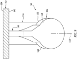
- the splash plate 132 of FIGS. 7 and 9 is configured with a (e.g., circular) puck-like body.
- the splash plate 132 of FIG. 7 extends axially along a centerline axis 154 of the splash plate 132 between a frontside splash plate surface 156 and a backside splash plate surface 158, which backside splash plate surface 158 is axially opposite the frontside splash plate surface 156.
- Each of these splash plate surfaces 156, 158 may have a generally circular shape; e.g., see FIG. 9 . However, in other embodiments, one or more of the splash plate surfaces 156, 158 may each have a non-circular (e.g., oval, polygonal, etc.) shape.
- Each of the splash plate surfaces 156, 158 may be configured as a smooth and/or planar surface. However, in other embodiments, one or more of the splash plate surfaces 156, 158 may each be configured as a non-planar (e.g., concave, convex, etc.) surface and/or with one or more flow disruptions; e.g., apertures or projections.
- the splash plate 132 of FIGS. 7 and 9 also includes at least one side perimeter surface 160 that extends axially between the opposing splash plate surfaces 156 and 158 and circumferentially about the centerline axis 154 of the splash plate 132.
- the splash plate 132 and, more particularly, its frontside splash plate surface 156 is angularly offset from the longitudinal centerline 146 by an angle 162 when viewed, for example, in a reference plane parallel with (e.g., that includes) the longitudinal centerline 146 of the nozzle passage 140 and/or the centerline axis 154 of the splash plate 132.
- the angle 162 may be an acute angle such as, but not limited to, between sixty degrees (60°) and eighty degrees (80°).
- the present disclosure is not limited to such an exemplary arrangement.
- the angle 162 may be less than sixty degrees (60°) or more than eighty degrees (80°).
- the splash plate 132 of FIGS. 7 and 9 is connected to the support member 130.
- the support member 130 also forms a pylon for connecting the splash plate 132 to the fuel nozzle 128 and/or the case wall 62.
- the splash plate 132 is disposed within and/or projects into the respective air passage 74.
- the splash plate 132 may alternatively be disposed just outside of the respective air tube 50B and its air passage 74.
- the fuel circuit 134 of FIG. 7 includes the fuel supply passage 96 and one or more or all of the nozzle passages 140.
- the fuel circuit 134 may thereby deliver the fuel received from the fuel source 94 (see FIG. 2 ) to each fuel injector 58 for injection. More particularly, during turbine engine operation, the fuel is directed into the fuel supply passage 96 from the fuel source 94 (see FIG. 2 ). At least a portion (or all) of the fuel within the fuel supply passage 96 is directed into the nozzle passage 140.
- this fuel flows through the nozzle passage 140 and out of the fuel nozzle 128 through the nozzle orifice 150 and into a spatial gap between the fuel nozzle 128 and the splash plate 132 as a fuel jet along a fuel jet trajectory 164, which may be parallel (e.g., coaxial) with the longitudinal centerline 146.
- This fuel jet may be a linear concentrated flow / stream of the fuel versus, for example, a spread-out pattern of fuel such as a conical film of fuel.
- the fuel jet flows through the spatial gap along its trajectory 164 and impacts (e.g., impinges against) the frontside splash plate surface 156 at a target area; e.g., an impingement area.
- the splash plate 132 Upon impacting the frontside splash plate surface 156, the splash plate 132 redirects (e.g., disperses) the impinging fuel jet radially outward (relative to the fuel jet trajectory 164) into a (e.g., uniform and/or symmetrical) radiant pattern; e.g., an arcuate and/or a generally planar film schematically shown in FIG. 7 via discrete flow arrows.
- the fuel may thereby be more evenly dispersed / spread / mixed into the compressed core air flowing past the fuel nozzle 128 and the splash plate 132 within the air passage 74. Providing such relatively even mixing of the fuel and the compressed core air may in turn increase fuel burn efficiency and/or reduce likelihood of carbon formation within the turbine engine 20.
- the combustion process may be temporarily starved of oxygen.
- the combustion process may initially be starved of oxygen until the compressor section 31 has time to spool up and provide the compressed core air.
- the gas circuit 136 of FIG. 7 is configured to deliver oxygen (e.g., oxygen (O 2 ) gas, or alternatively stored compressed air) to the combustor 46.
- oxygen e.g., oxygen (O 2 ) gas, or alternatively stored compressed air
- this gas circuit 136 includes the gas supply passage 108, the intermediate coupler 110 and the gas line 122.
- the gas circuit 136 also includes one or more (e.g., oxygen (O 2 )) gas passages 166, where each gas passage 166 may be configured with a respective one of the fuel injectors 58.
- the gas passage 166 of FIG. 7 is formed by and is embedded within the support member 130 and the splash plate 132 of a respective fuel injector 58.
- the gas passage 166 of FIG. 7 for example, includes an upstream section 168 and a downstream section 170.
- the upstream section 168 of the gas passage 166 is fluidly coupled with and projects inward from the gas supply passage 108.
- the upstream section 168 of the gas passage 166 extends (e.g., radially and/or axially) through the support member 130 to the splash plate 132.
- the downstream section 170 of the gas passage 166 extends (e.g., radially and/or axially) through the splash plate 132 from the upstream section 168 of the gas passage 166 to a gas outlet 174 from the gas passage 166.
- the gas outlet 174 of FIG. 7 may be disposed in the side perimeter surface 160 and, thus, remote from the frontside splash plate surface 156 and/or the impinging fuel.
- the downstream section 170 of the gas passage 166 may also be configured to direct the gas out of the splash plate 132 through the gas outlet 174 and into the air passage 74 in a direction away from the fuel; see also FIG. 8 .
- the downstream section 170 of the gas passage 166 may direct the gas out of the gas outlet 174 into the air passage 74 in a direction that is parallel with the longitudinal centerline 76 (see FIG. 2 ) of the air tube 50B, or angularly offset from the longitudinal centerline 76 (see FIG. 2 ) by less than ten degrees (10°) or five degrees (5°).
- the gas may be supplied to the air passage 74 relatively close (e.g., as close as possible) to the combustion chamber 48.
- Injecting the gas within the air passage 74 close to the combustion chamber 48 may facilitate provision of (e.g., all of) the gas to the combustion chamber 48 for combustion without being blocked, redirected or temporarily obstructed by, for example, the fuel dispersed by the splash plate 132.
- At least a portion of the static engine structure 36 may be formed in a monolithic body 176.
- the term "monolithic” may described a body which is additively manufactured, cast, machined and/or otherwise formed as a single unitary body.
- a non-monolithic body may include multiple discretely formed bodies which are attached to one another following formation thereof. The present disclosure, however, is not limited to such an exemplary monolithic configuration nor to the foregoing exemplary manufacturing techniques.
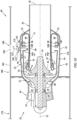
- the vehicle system 60 may also include a vehicle airframe 178.
- This vehicle airframe 178 may include an airframe body 180 and one or more airfoils 182 (e.g., wings, stabilizers, etc.) connected to and projecting outwards from the airframe body 180.
- the turbine engine 20 may be arranged within and connected to the vehicle airframe 178.
- the turbine engine 20, for example may be (e.g., completely) housed within the vehicle airframe 178 and its airframe body 180.
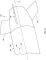
- the airframe body 180 may form an outer aerodynamic surface 184 for the aerial vehicle; see also FIG. 11 .
- the airframe body 180 for example, may be configured as a nacelle for the turbine engine 20.
- the airframe body 180 may also or alternatively be configured as a fuselage and/or another airframe component for the aerial vehicle.
- At least a portion of the airframe body 180 may be formed integral with at least a portion of the static engine structure 36. At least a portion of the airframe body 180, for example, may be included in the monolithic body 176. In such embodiments, the airframe body 180 may block access to one or more locations on the case wall 62. To provide access to the mounting boss 120 for providing the mounting boss 120 with a flat mounting surface 186 (see also FIG. 5 ) to receive the gas line fitting 116, the airframe body 180 may be provided with an access port 188. This access port 188 projects (e.g., radially) through a sidewall of the airframe body 180.
- the access port 188 is positioned radially outboard of and (e.g., axially and/or circumferentially) overlaps the mounting boss 120 and/or the gas line fitting 116. With this configuration, a machining tool may be inserted through the access port 188 during manufacture to machine (e.g., plane) the mounting boss 120 and provide the mounting surface 186. However, during aerial vehicle operation, the access port 188 may be covered and closed using, for example, a cover panel 190 (see dashed line).
- the vehicle system 60 may be configured with various turbine engines other than the one described above.
- the vehicle system 60 may be configured with a geared turbine engine where a geartrain connects one or more shafts to one or more rotors in a fan section, a compressor section and/or any other engine section.
- the vehicle system 60 may be configured with a turbine engine configured without a geartrain; e.g., a direct drive turbine engine.
- the vehicle system 60 may be configured with a geared or non-geared turbine engine configured with a single spool (e.g., see FIG. 1 ), with two spools, or with more than two spools.
- the turbine engine may be configured as a turbofan engine, a turbojet engine, a propfan engine, a pusher fan engine or any other type of turbine engine.
- the present disclosure therefore is not limited to any particular types or configurations of turbine engines.
- the present disclosure is also not limited to a propulsion system application.
- the gas turbine engine may alternatively be configured as an auxiliary power unit (APU) or an industrial gas turbine engine.
- APU auxiliary power unit
Landscapes
- Engineering & Computer Science (AREA)
- Chemical & Material Sciences (AREA)
- Combustion & Propulsion (AREA)
- Mechanical Engineering (AREA)
- General Engineering & Computer Science (AREA)
- Fuel-Injection Apparatus (AREA)
Abstract
Description
- This disclosure relates generally to a turbine engine and, more particularly, to a fuel injector for the turbine engine.
- A combustor section in a modern turbine engine includes one or more fuel injectors. Each fuel injector is operable to inject fuel for combustion within a combustion chamber. Various types and configurations of fuel injectors are known in the art. While these known fuel injectors have various benefits, there is still room in the art for improvement. There is a need in the art, for example, for a fuel injector which can facilitate turbine engine start up a relatively high altitude.
- According to an aspect of the present invention, a system is provided for an aerial vehicle. This system includes a splash plate, a fuel nozzle and a gas circuit. The splash plate includes a splash plate surface. The fuel nozzle includes a nozzle orifice. The fuel nozzle is configured to direct fuel out of the nozzle orifice to impinge against the splash plate surface. The gas circuit includes a gas passage and a gas outlet. At least a portion of the gas passage is formed by and embedded within the splash plate. The gas passage extends through the splash plate to the gas outlet.
- According to another aspect of the present invention, another system is provided for an aerial vehicle. This system includes a case wall, a fuel injector, a fuel circuit and a gas circuit. The case wall extends axially along and circumferentially about an axial centerline. The fuel injector is connected to and radially inboard of the case wall. The fuel circuit is configured to deliver fuel to the fuel injector. The fuel circuit includes a fuel supply passage integrated with the case wall. The fuel supply passage extends along the case wall circumferentially about the axial centerline. The gas circuit is configured to deliver oxygen gas to the fuel injector. The gas circuit includes a gas supply passage embedded within the case wall. The gas supply passage extends within the case wall circumferentially about the axial centerline.
- According to still another aspect of the present invention, another system is provided for an aerial vehicle. This system includes an airframe body, a turbine engine, a gas circuit and an oxygen gas source. The airframe body includes an access port. The turbine engine is housed within the airframe body. The turbine engine includes a case wall and a fuel injector. The case wall includes a boss radially inboard of and overlapped by the access port. At least the airframe body and the case wall are configured together in a monolithic body. The fuel injector is radially inboard of the case wall. The gas circuit is configured to deliver oxygen gas to the fuel injector. The gas circuit includes a gas line fitting and a gas supply passage embedded within the case wall. The gas supply passage extends within the case wall circumferentially about an axial centerline of the turbine engine. The gas line fitting is bonded to the boss. The oxygen gas source is fluidly coupled to the gas supply passage through the gas line fitting.
- The following optional features may be applied individually, or in any combination, to any of the above aspects of the invention:
The fuel injector may include a splash plate and a fuel nozzle. The fuel nozzle may include a nozzle orifice fluidly coupled with and downstream of the fuel supply passage. The fuel nozzle may be configured to direct the fuel out of the nozzle orifice to impinge against the splash plate. The gas circuit may also include a gas passage and a gas orifice in a surface of the splash plate. The gas passage may be fluidly coupled with and downstream of the gas supply passage. The gas passage may extend through the splash plate to the gas orifice. - The system may also include a second fuel injector connected to and radially inboard of the case wall. The fuel circuit may also be configured to deliver the fuel to the second fuel injector. The gas circuit may also be configured to deliver the oxygen gas to the second fuel injector.
- The system may also include a monolithic body, and the monolithic body may include the case wall and the fuel injector.
- The system may also include a gas source fluidly coupled with the gas circuit. The gas circuit may be configured to receive gas from the gas source. The gas passage may be configured to direct the gas to the gas outlet.
- The gas source may be configured as or otherwise include a gas reservoir.
- The gas received by the gas circuit from the gas source may be (e.g., consist of) oxygen gas.
- The gas outlet may be located remote from the splash plate surface.
- The splash plate may also include a second surface. The gas outlet may be disposed in the second surface.
- The second surface may be adjacent the splash plate surface.
- The gas circuit may be configured to direct gas out of the gas outlet downstream of the splash plate surface. The downstream direction may be defined relative to a direction of airflow through the aerial vehicle, where the aerial vehicle may be a turbine engine.
- The gas circuit may be configured to direct gas out of the gas outlet along a trajectory angularly offset from the splash plate surface and away from the fuel impinging against the splash plate surface.
- The system may also include an air tube including (or defining) an air passage. The fuel nozzle may project into the air passage. The splash plate may be arranged at least partially within the air passage such that the splash plate is configured to direct at least some of the fuel against an inner sidewall surface of the air tube.
- The gas circuit may be configured to direct gas out of the gas outlet into the air passage along a trajectory that is parallel with a centerline of the air tube or angularly offset from (e.g. not parallel to) the centerline of the air tube by less than ten degrees.
- The system may also include a combustor wall at least partially forming a combustion chamber. The air tube may be connected to the combustor wall and may project into the combustion chamber.
- The system may also include a case wall and a support member. The fuel nozzle may be connected to and project inward from the case wall. The support member may be connected to and extend between the case wall and the fuel nozzle. The splash plate may be connected to the support member.
- The support member may be configured as or otherwise include a strut.
- Another portion of the gas passage (the another portion being a different, or second, portion to the at least one portion of the gas passage defined above) may be formed by and embedded within the support member. The gas passage may extend though the support member from the case wall to the splash plate.
- The system may also include a case wall extending axially along and circumferentially about an axial centerline. The gas circuit may also include a supply passage formed by and embedded within the case wall. The supply passage may extend circumferentially about the axial centerline. The gas passage may be fluidly coupled with and downstream of the supply passage.
- The case wall may include a boss. The gas circuit may also include a gas line fitting bonded to the boss. The supply passage may be fluidly coupled with and downstream of the gas line fitting.
- The system may also include an airframe body and a turbine engine. The airframe body includes an access port. The turbine engine may be housed within the airframe body. The turbine engine may include the splash plate, the fuel nozzle and the case wall. The access port may be radially outboard of and overlap the boss and the gas line fitting.
- In an embodiment of any of the above, there may be provided an aerial vehicle comprising the system of any of the above, or there may be a turbine engine comprising the system of any of the above, or there may be a aerial vehicle comprising a turbine engine comprising the system of any of the above. The aerial vehicle and/or turbine engine may have a central axis defining an or the axial centerline. The central axis may also define a radial direction, and any reference to a `radially outboard' and `radially inboard' above may be defined relative to this radial direction. Any reference to a 'downstream' direction may be defined in relation to a direction of airflow through the aerial vehicle and/or turbine engine. The axial centerline of the case wall as defined above may be in line with the axial centerline of the aerial vehicle and/or turbine engine.
- The present disclosure may include any one or more of the individual features disclosed above and/or below alone or in any combination thereof.
- The foregoing features and the operation of the invention will become more apparent in light of the following description and the accompanying drawings.
-
-
FIG. 1 is a schematic side sectional illustration of a turbine engine for an aerial vehicle. -
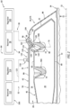
FIG. 2 is a partial schematic illustration of a system for the aerial vehicle. -
FIG. 3 is a cross-sectional illustration through a turbine engine. -
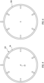
FIG. 4 is a schematic illustration of a portion of a fuel circuit with an annular fuel supply passage. -
FIG. 5 is a partial perspective illustration of a turbine engine at a gas line fitting. -
FIG. 6 is a schematic illustration of a portion of a gas circuit with an annular gas supply passage. -
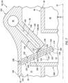
FIG. 7 is a partial sectional illustration of a turbine engine at a fuel injector. -
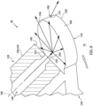
FIG. 8 is a side cutaway illustration of a portion of the fuel injector ofFIG. 7 schematically depicting various fluid flows during engine operation. -
FIG. 9 is a perspective cutaway illustration of the turbine engine at the fuel injector. -
FIG. 10 is a schematic side sectional illustration of the turbine engine housed within a vehicle airframe. -
FIG. 11 is a partial perspective illustration of an exterior of the vehicle airframe. -
FIG. 1 illustrates agas turbine engine 20 for an aerial vehicle such as, but not limited to, an unmanned aerial vehicle (UAV), a drone or any other manned or unmanned aircraft or self-propelled projectile. Theturbine engine 20 ofFIG. 1 is configured as a single spool, radial-flow turbojet gas turbine engine. Thisturbine engine 20 is configured for propelling the aerial vehicle during flight. The present disclosure, however, is not limited to such an exemplary turbojet gas turbine engine configuration nor to a vehicle propulsion system application. For example, theturbine engine 20 may alternatively be configured as an auxiliary power unit (APU) for the aerial vehicle. - The
turbine engine 20 ofFIG. 1 extends axially along anaxial centerline 22 between a forward,upstream airflow inlet 24 into theturbine engine 20 and an aft,downstream exhaust 26 out of theturbine engine 20. Thisaxial centerline 22 may be a centerline axis of theturbine engine 20. Theaxial centerline 22 may also or alternatively be a rotational axis for one or more components within theturbine engine 20. - The
turbine engine 20 includes acore flowpath 28, aninlet section 30, a (e.g., radial flow)compressor section 31, a (e.g., reverse flow)combustor section 32, a (e.g., radial flow)turbine section 33 and anexhaust section 34. Theturbine engine 20 also includes astatic engine structure 36 housing and/or forming one or more or all of the engine sections 30-34. - The
core flowpath 28 extends within theturbine engine 20 between theengine inlet 24 and theengine exhaust 26. More particularly, thecore flowpath 28 extends sequentially through theinlet section 30, thecompressor section 31, thecombustor section 32, theturbine section 33 and theexhaust section 34 from theengine inlet 24 to theengine exhaust 26. - The
compressor section 31 includes abladed compressor rotor 38. Theturbine section 33 includes a bladedturbine rotor 40. Each of theseengine rotors - The
compressor rotor 38 may be configured as a radial flow compressor rotor. Theturbine rotor 40 may be configured as a radial flow turbine rotor. Thecompressor rotor 38 is connected to theturbine rotor 40 through anengine shaft 42. Thisengine shaft 42 is rotatably supported by thestatic engine structure 36 through a plurality ofbearings 44; e.g., rolling element bearings, journal bearings, etc. - The
combustor section 32 includes anannular combustor 46 with anannular combustion chamber 48. Thecombustor 46 ofFIG. 1 is configured as a reverse flow combustor.Air tubes combustion chamber 48, for example, may be arranged at (e.g., on, adjacent or proximate) and/or towards anaft bulkhead wall 52 of thecombustor 46. An outlet from thecombustor 46 may be arranged axially aft of an inlet to theturbine section 33. Thecombustor 46 may also be arranged radially outboard of and/or axially overlap at least a portion (e.g., aft portion) of theturbine section 33. With this arrangement, thecore flowpath 28 ofFIG. 1 reverses direction (e.g., from a forward-to-aft direction to an aft-to-forward direction) a first time as thecore flowpath 28 extends from adiffuser plenum 54 surrounding thecombustor 46 into thecombustion chamber 48. The core flowpath 28 ofFIG. 1 then reverses its direction (e.g., from the aft-to-forward direction to the forward-to-aft direction) a second time as thecore flowpath 28 extends from thecombustion chamber 48 into theturbine section 33. - During operation, air enters the
turbine engine 20 through theinlet section 30 and itsengine inlet 24. Theinlet section 30 directs this air from theengine inlet 24 into thecore flowpath 28 and thecompressor section 31. The air within thecore flowpath 28 may be referred to as core air. This core air is compressed by thecompressor rotor 38 and directed through adiffuser 56 and itsdiffuser plenum 54 into thecombustion chamber 48. Fuel is injected via one ormore fuel injectors 58 and mixed with the compressed core air to provide a fuel-air mixture. This fuel-air mixture is ignited within thecombustion chamber 48, and combustion products thereof flow through theturbine section 33 and cause theturbine rotor 40 to rotate. The rotation of theturbine rotor 40 drives rotation of thecompressor rotor 38 and, thus, compression of the air received from theengine inlet 24. Theexhaust section 34 receives the combustion products from theturbine section 33. Theexhaust section 34 directs the received combustion products out of theturbine engine 20 to provide, for example, forward engine thrust. -
FIG. 2 illustrates a portion of asystem 60 for the aerial vehicle. Thisvehicle system 60 includes at least a portion of thestatic engine structure 36 within / forming thecombustor section 32. Thestatic engine structure 36 includes thecombustor 46 and acase wall 62 surrounding thecombustor 46. Thevehicle system 60 also includes a fuel andgas injection system 64. - The
combustor 46 ofFIG. 2 includes anouter combustor wall 66, aninner combustor wall 68 and thebulkhead wall 52. Theouter combustor wall 66 extends axially along theaxial centerline 22 between and may be connected to an outer platform of a turbine nozzle 70 (seeFIG. 1 ) and thebulkhead wall 52. Theouter combustor wall 66 extends circumferentially about (e.g., circumscribes), axially overlaps and is spaced radially outward from theinner combustor wall 68. Theinner combustor wall 68 extends axially between an inner platform of the turbine nozzle 70 (seeFIG. 1 ) and thebulkhead wall 52, and theinner combustor wall 68 may be connected to thebulkhead wall 52. Theinner combustor wall 68 extends circumferentially about (e.g., circumscribes), axially overlaps and is spaced radially outward from a turbine case 72 (see alsoFIG. 1 ). Thebulkhead wall 52 extends radially between theouter combustor wall 66 and theinner combustor wall 68, at aft ends of thecombustor walls combustor walls combustion chamber 48 within thecombustor 46. - The
combustor 46 ofFIG. 2 also includes one or more sets of the air tubes 50. Referring toFIG. 3 , the air tubes 50 in each set are arranged circumferentially about theaxial centerline 22 in a circular array. Referring toFIG. 2 , each of the air tubes 50 is connected to (e.g., formed integral with or otherwise attached to) theouter combustor wall 66. Each of the air tubes 50 projects radially inward from theouter combustor wall 66 partially into thecombustion chamber 48 to a distal inner end of the respective air tube 50. Each air tube 50 has aninternal air passage 74; e.g., an inner bore of the respective air tube 50. Thisair passage 74 extends longitudinally along alongitudinal centerline 76 of the respective air tube 50 and/or therespective air passage 74 through the air tube 50. More particularly, theair passage 74 extends longitudinally from aninlet 78 into theair passage 74 to anoutlet 80 from theair passage 74. Theair passage inlet 78 ofFIG. 2 is disposed at an outer end of the respective air tube 50. Theair passage outlet 80 ofFIG. 2 is disposed at the inner end of the respective air tube 50. With this arrangement, each air tube 50 and itsair passage 74 fluidly couples thediffuser plenum 54 outside of thecombustor 46 and radially outboard of theouter combustor wall 66 with thecombustion chamber 48 inside of thecombustor 46 and radially inboard of theouter combustor wall 66. - When viewed in a first reference plane parallel with (e.g., that includes) the axial centerline 22 (e.g., plane of
FIG. 2 ), eachlongitudinal centerline 76 may be perpendicular to theaxial centerline 22, or angularly offset from theaxial centerline 22 by less than ten degrees (10°) or five degrees (5°). When viewed in a second reference plane perpendicular to the axial centerline 22 (e.g., plane ofFIG. 3 ), eachlongitudinal centerline 76 may be angularly offset from areference line 82 by anangle 84. Thereference line 82 may be a ray projecting radially out from theaxial centerline 22 to (e.g., a center of) theair passage inlet 78 associated with the respectivelongitudinal centerline 76. Theangle 84 may be a (e.g., non-zero) acute angle between, for example, ten degrees (10°) and forty-five degrees (45°). The present disclosure, however, is not limited to the foregoing exemplary air tube / air passage configurations. The air tubes 50, for example, may be alternatively arranged to tailor combustion dynamics within thecombustion chamber 48. - Referring to
FIG. 2 , thecase wall 62 may be configured as an outer case of thediffuser 56; e.g., an outer diffuser case. Thecase wall 62 ofFIG. 2 , for example, is configured to at least partially house thecombustor 46 within thecombustor section 32. Thecase wall 62 ofFIG. 2 , in particular, includes asidewall section 86 and anendwall section 88. Thecase wall 62 and itssidewall section 86 extend circumferentially about (e.g., circumscribe), axially overlap and are spaced radially outward from thecombustor 46 and itsouter combustor wall 66. Thecase wall 62 may thereby form an outer peripheral boundary of thecore flowpath 28 and thediffuser plenum 54 along thecombustor 46. Thecase wall 62 and itsendwall section 88 extend radially inwards from an aft, downstream end of thesidewall section 86 to the turbine case 72 (see alsoFIG. 1 ). Thecase wall 62 and itsendwall section 88 thereby radially overlap and are spaced axially aft from thecombustor 46 and itsbulkhead wall 52. - The fuel and
gas injection system 64 includes afuel delivery system 90 and a (e.g., oxygen (O2))gas delivery system 92. The fuel andgas injection system 64 also includes the one ormore fuel injectors 58, where eachfuel injector 58 receives fuel from thefuel delivery system 90 and eachfuel injector 58 may receive (e.g., oxygen (O2)) gas from thegas delivery system 92. - The
fuel delivery system 90 includes afuel source 94 and afuel supply passage 96. Thefuel source 94 is configured to contain fuel before, during and/or after turbine engine operation. Thefuel source 94 is also configured to deliver the fuel to thefuel supply passage 96 to facilitate turbine engine operation. Thefuel source 94, for example, may be configured as or otherwise include afuel reservoir 98 and/or afuel regulator 100. Examples of thefuel reservoir 98 include, but are not limited to, a container, a tank, a pressure vessel and a bladder. Examples of thefuel regulator 100 include, but are not limited to, a pump and a valve system. Thefuel regulator 100 may flow, pump and/or otherwise direct fuel received from the fuel reservoir 98 (and/or elsewhere) to thefuel supply passage 96. The fuel may be a hydrocarbon fuel such as, but not limited to, kerosene or jet fuel. It is contemplated, however, that the fuel may alternatively be a non-hydrocarbon fuel such as, but not limited to ammonia or hydrogen. - The
fuel supply passage 96 may be configured in, or included as part of, a fuel supply tube and/or a fuel manifold for one or more or all of thefuel injectors 58. Thefuel supply passage 96 ofFIG. 2 , for example, is formed by aconduit 102. Thisfuel supply conduit 102 is arranged at anouter side 104 of thecase wall 62. Thefuel supply conduit 102 may be formed integral with (or otherwise attached to) thecase wall 62. Referring toFIG. 4 , thefuel supply conduit 102 and itsfuel supply passage 96 extend circumferentially about (e.g., completely around) theaxial centerline 22. With such a configuration, thefuel supply passage 96 may have a full-hoop (e.g., annular) geometry. Thefuel supply conduit 102 and itsfuel supply passage 96, however, may alternatively extend partially circumferentially about theaxial centerline 22. Furthermore, while thefuel supply conduit 102 is shown as a protrusion out from thecase wall 62 inFIG. 2 , it is contemplated thefuel supply passage 96 may alternatively be formed by and embedded within thecase wall 62. - The
gas delivery system 92 ofFIG. 2 includes a (e.g., oxygen (O2))gas source 106 and a (e.g., oxygen (O2)) gas supply passage 108 (seeFIG. 5 ). Thegas delivery system 92 may also include an intermediate coupler 110 (seeFIG. 5 ) between thegas source 106 and thegas supply passage 108. - The
gas source 106 is configured to contain pressurized gas (e.g., pressurized oxygen (O2) or pressurized air) before, during and/or after turbine engine operation. Thegas source 106 is also configured to deliver the gas to thegas supply passage 108 to facilitate turbine engine operation. Thegas source 106, for example, may be configured as or otherwise include agas reservoir 112 and/or agas regulator 114. Examples of thegas reservoir 112 include, but are not limited to, a container, a tank, a pressure vessel and a bladder. An example of thegas regulator 114 is, but is not limited to, a valve system. Thegas regulator 114 may selectively flow and/or otherwise direct the gas received from the gas reservoir 112 (and/or elsewhere) to thegas supply passage 108. - Referring to
FIG. 5 , thegas supply passage 108 may be configured in, or included as part of, a gas supply tube and/or a gas manifold for one or more or all of thefuel injectors 58. Thegas supply passage 108 ofFIG. 5 may be formed by and embedded within thecase wall 62; see alsoFIG. 7 . Referring toFIG. 6 , thegas supply passage 108 extends circumferentially about (e.g., completely around) theaxial centerline 22. With such a configuration, thegas supply passage 108 may have a full-hoop (e.g., annular) geometry. Thegas supply passage 108, however, may alternatively extend partially circumferentially about theaxial centerline 22. Furthermore, while thegas supply passage 108 is shown as being embedded within thecase wall 62 ofFIG. 2 , it is contemplated that some or all of thegas supply passage 108 may alternatively be formed by a conduit integrated with or otherwise attached to thecase wall 62. - Referring to
FIG. 5 , theintermediate coupler 110 may include a gas line fitting 116 and aconduit 118. The gas line fitting 116 is attached to thecase wall 62. The gas line fitting 116 ofFIG. 5 , for example, is bonded (e.g., welded or brazed) to a mountingboss 120 on theouter side 104 of thecase wall 62. The gas line fitting 116 provides an interface for mounting agas line 122 to theintermediate coupler 110. By attaching the gas line fitting 116 to the mountingboss 120, machining operations to thestatic engine structure 36 may be reduced. For example, rather than tapping a bore of the mountingboss 120 to receive an end of thegas line 122, the gas line fitting 116 is provided to mate with thegas line 122. This may be particularly useful where at least a portion of thestatic engine structure 36 which includes thecase wall 62 is formed via additive manufacturing and, thus, it may be difficult to remove machining debris from internal passages. - The
coupler conduit 118 ofFIG. 5 includes an upstream (e.g., axial)section 124 and a downstream (e.g., circumferential)section 126. Thiscoupler conduit 118 is arranged at theouter side 104 of thecase wall 62. Thecoupler conduit 118 may be formed integral with (or otherwise attached to) thecase wall 62. Theupstream section 124 of thecoupler conduit 118 extends axially along thecase wall 62 from the mountingboss 120 to thedownstream section 126 of thecoupler conduit 118. Thedownstream section 126 of thecoupler conduit 118 extends circumferentially along thecase wall 62 from theupstream section 124 of thecoupler conduit 118 to an intersection with thegas supply passage 108. - With the foregoing configuration, the
intermediate coupler 110 and a passage therethrough may fluidly couple the gas source 106 (seeFIG. 2 ) to thegas supply passage 108. In particular, the gas line fitting 116 fluidly couples thegas line 122 and, thus, the gas source 106 (seeFIG. 2 ) to thecoupler conduit 118. Thecoupler conduit 118 in turn fluidly couples the gas line fitting 116 to thegas supply passage 108. However, it is contemplated the some or all of thecoupler conduit 118 may be omitted. For example, thedownstream section 126 of thecoupler conduit 118 may be omitted where thegas supply passage 108 interfaces with an end of theupstream section 124 of thecoupler conduit 118. In another example, theentire coupler conduit 118 may be omitted where thegas supply passage 108 interfaces with the gas line fitting 116 through the bore of the mountingboss 120. - Referring to
FIG. 3 , thefuel injectors 58 are arranged circumferentially about theaxial centerline 22 in a circular array. Eachfuel injector 58 may be arranged with a respective one of theair tubes 50B as described below in further detail. While thefuel injectors 58 are illustrated as being arranged with every-other air tube 50B in air tube set ofFIG. 3 , the present disclosure is not limited to such an exemplary embodiment. Thefuel injectors 58, for example, may alternatively be arranged with everyair tube 50B in a respective air tube set, with every second orthird air tube 50B in a respective air tube set, etc. - Referring to
FIG. 7 , eachfuel injector 58 includes afuel nozzle 128, a support member 130 (e.g., a strut, a frame, a web, etc.) and asplash plate 132. Eachfuel injector 58 is configured with afuel circuit 134 and a (e.g., oxygen (O2))gas circuit 136. - The
fuel nozzle 128 is configured to receive the fuel from thefuel supply passage 96. Thefuel nozzle 128 is also configured to inject the received fuel into a respective one of theair passages 74 to impinge against thesplash plate 132. Thefuel nozzle 128 ofFIG. 7 includes a nozzle body 138 and anozzle passage 140; e.g., a fuel passage. - The nozzle body 138 is arranged at and/or is connected to an
inner side 142 of thecase wall 62, where the wallinner side 142 is opposite the wallouter side 104. The nozzle body 138 ofFIG. 7 is configured as or may otherwise include a nozzle tube 144. A base end of the nozzle tube 144 is connected to (e.g., formed integral with or otherwise attached to) thecase wall 62. The nozzle tube 144 projects (e.g., radially and/or axially) out from thecase wall 62 along a (e.g., straight or curved)longitudinal centerline 146 of thenozzle passage 140 and/or the nozzle tube 144 to an innerdistal end 148 of thefuel nozzle 128. - An internal bore of the nozzle tube 144 at least partially (or completely) forms the
nozzle passage 140. Thenozzle passage 140 extends longitudinally along thelongitudinal centerline 146 within and/or through thecase wall 62 and the nozzle tube 144 from thefuel supply passage 96 to adownstream nozzle orifice 150 at the fuel nozzledistal end 148. Thisnozzle orifice 150 provides an outlet from thenozzle passage 140 and, more generally, thefuel nozzle 128. - The
support member 130 extends (e.g., radially and/or axially) between thecase wall 62 and a side of the nozzle tube 144. Thesupport member 130 is connected to (e.g., formed integral with or otherwise attached to) thecase wall 62 and the nozzle tube 144. Thesupport member 130 may thereby structurally tie the nozzle tube 144 to thecase wall 62 and support the nozzle tube 144 within thediffuser plenum 54 and/or therespective air passage 74. Thesupport member 130, for example, may form a support brace for the nozzle tube 144. Thesupport member 130 may also provide a support for the nozzle tube 144 while forming (e.g., additively manufacturing) thefuel nozzle 128. - The
splash plate 132 is configured to redirect (e.g., disperse) the fuel injected into theair passage 74 from thefuel nozzle 128 into a widespread pattern (e.g., seeFIG. 8 ). Thesplash plate 132, for example, is arranged proximate and laterally overlaps thenozzle orifice 150. Thesplash plate 132 is longitudinally spaced from thefuel nozzle 128 and itsnozzle orifice 150 by a longitudinal distance along thelongitudinal centerline 146. This longitudinal distance may be equal to or different (e.g., greater or less) than a width (e.g., diameter) of thenozzle passage 140. The longitudinal distance ofFIG. 7 , for example, is between one-half times (0.5x) and five times (5x) a width (e.g., a diameter) of athroat portion 152 of thenozzle passage 140. The present disclosure, however, is not limited to the foregoing exemplary dimensional relationship between thesplash plate 132 and thefuel nozzle 128. - The
splash plate 132 ofFIGS. 7 and9 is configured with a (e.g., circular) puck-like body. Thesplash plate 132 ofFIG. 7 , for example, extends axially along acenterline axis 154 of thesplash plate 132 between a frontsidesplash plate surface 156 and a backsidesplash plate surface 158, which backsidesplash plate surface 158 is axially opposite the frontsidesplash plate surface 156. Each of these splash plate surfaces 156, 158 may have a generally circular shape; e.g., seeFIG. 9 . However, in other embodiments, one or more of the splash plate surfaces 156, 158 may each have a non-circular (e.g., oval, polygonal, etc.) shape. Each of the splash plate surfaces 156, 158 may be configured as a smooth and/or planar surface. However, in other embodiments, one or more of the splash plate surfaces 156, 158 may each be configured as a non-planar (e.g., concave, convex, etc.) surface and/or with one or more flow disruptions; e.g., apertures or projections. Thesplash plate 132 ofFIGS. 7 and9 also includes at least oneside perimeter surface 160 that extends axially between the opposing splash plate surfaces 156 and 158 and circumferentially about thecenterline axis 154 of thesplash plate 132. - Referring to
FIG. 7 , thesplash plate 132 and, more particularly, its frontsidesplash plate surface 156 is angularly offset from thelongitudinal centerline 146 by anangle 162 when viewed, for example, in a reference plane parallel with (e.g., that includes) thelongitudinal centerline 146 of thenozzle passage 140 and/or thecenterline axis 154 of thesplash plate 132. Theangle 162 may be an acute angle such as, but not limited to, between sixty degrees (60°) and eighty degrees (80°). The present disclosure, however, is not limited to such an exemplary arrangement. For example, in other embodiments, theangle 162 may be less than sixty degrees (60°) or more than eighty degrees (80°). - The
splash plate 132 ofFIGS. 7 and9 is connected to thesupport member 130. In particular, in addition to supporting the nozzle tube 144, thesupport member 130 also forms a pylon for connecting thesplash plate 132 to thefuel nozzle 128 and/or thecase wall 62. Referring toFIG. 7 , thesplash plate 132 is disposed within and/or projects into therespective air passage 74. However, it is contemplated thesplash plate 132 may alternatively be disposed just outside of therespective air tube 50B and itsair passage 74. - The
fuel circuit 134 ofFIG. 7 includes thefuel supply passage 96 and one or more or all of thenozzle passages 140. Thefuel circuit 134 may thereby deliver the fuel received from the fuel source 94 (seeFIG. 2 ) to eachfuel injector 58 for injection. More particularly, during turbine engine operation, the fuel is directed into thefuel supply passage 96 from the fuel source 94 (seeFIG. 2 ). At least a portion (or all) of the fuel within thefuel supply passage 96 is directed into thenozzle passage 140. Referring toFIG. 8 , this fuel flows through thenozzle passage 140 and out of thefuel nozzle 128 through thenozzle orifice 150 and into a spatial gap between thefuel nozzle 128 and thesplash plate 132 as a fuel jet along afuel jet trajectory 164, which may be parallel (e.g., coaxial) with thelongitudinal centerline 146. This fuel jet may be a linear concentrated flow / stream of the fuel versus, for example, a spread-out pattern of fuel such as a conical film of fuel. The fuel jet flows through the spatial gap along itstrajectory 164 and impacts (e.g., impinges against) the frontsidesplash plate surface 156 at a target area; e.g., an impingement area. Upon impacting the frontsidesplash plate surface 156, thesplash plate 132 redirects (e.g., disperses) the impinging fuel jet radially outward (relative to the fuel jet trajectory 164) into a (e.g., uniform and/or symmetrical) radiant pattern; e.g., an arcuate and/or a generally planar film schematically shown inFIG. 7 via discrete flow arrows. The fuel may thereby be more evenly dispersed / spread / mixed into the compressed core air flowing past thefuel nozzle 128 and thesplash plate 132 within theair passage 74. Providing such relatively even mixing of the fuel and the compressed core air may in turn increase fuel burn efficiency and/or reduce likelihood of carbon formation within theturbine engine 20. - Under certain conditions however, the combustion process may be temporarily starved of oxygen. For example, when starting (or restarting) the
turbine engine 20 ofFIG. 1 at high altitudes, the combustion process may initially be starved of oxygen until thecompressor section 31 has time to spool up and provide the compressed core air. To facilitate turbine engine operation under such conditions, thegas circuit 136 ofFIG. 7 is configured to deliver oxygen (e.g., oxygen (O2) gas, or alternatively stored compressed air) to thecombustor 46. Referring toFIGS. 2 ,5 and7 , thisgas circuit 136 includes thegas supply passage 108, theintermediate coupler 110 and thegas line 122. Referring toFIG. 7 , thegas circuit 136 also includes one or more (e.g., oxygen (O2))gas passages 166, where eachgas passage 166 may be configured with a respective one of thefuel injectors 58. - The
gas passage 166 ofFIG. 7 is formed by and is embedded within thesupport member 130 and thesplash plate 132 of arespective fuel injector 58. Thegas passage 166 ofFIG. 7 , for example, includes anupstream section 168 and adownstream section 170. Theupstream section 168 of thegas passage 166 is fluidly coupled with and projects inward from thegas supply passage 108. Theupstream section 168 of thegas passage 166 extends (e.g., radially and/or axially) through thesupport member 130 to thesplash plate 132. Thedownstream section 170 of thegas passage 166 extends (e.g., radially and/or axially) through thesplash plate 132 from theupstream section 168 of thegas passage 166 to agas outlet 174 from thegas passage 166. Thegas outlet 174 ofFIG. 7 may be disposed in theside perimeter surface 160 and, thus, remote from the frontsidesplash plate surface 156 and/or the impinging fuel. Thedownstream section 170 of thegas passage 166 may also be configured to direct the gas out of thesplash plate 132 through thegas outlet 174 and into theair passage 74 in a direction away from the fuel; see alsoFIG. 8 . Thedownstream section 170 of thegas passage 166, for example, may direct the gas out of thegas outlet 174 into theair passage 74 in a direction that is parallel with the longitudinal centerline 76 (seeFIG. 2 ) of theair tube 50B, or angularly offset from the longitudinal centerline 76 (seeFIG. 2 ) by less than ten degrees (10°) or five degrees (5°). With this arrangement, the gas may be supplied to theair passage 74 relatively close (e.g., as close as possible) to thecombustion chamber 48. Injecting the gas within theair passage 74 close to thecombustion chamber 48 may facilitate provision of (e.g., all of) the gas to thecombustion chamber 48 for combustion without being blocked, redirected or temporarily obstructed by, for example, the fuel dispersed by thesplash plate 132. - In some embodiments, referring to
FIG. 2 , at least a portion of thestatic engine structure 36, which includes any one or more or all of themembers monolithic body 176. Herein, the term "monolithic" may described a body which is additively manufactured, cast, machined and/or otherwise formed as a single unitary body. By contrast, a non-monolithic body may include multiple discretely formed bodies which are attached to one another following formation thereof. The present disclosure, however, is not limited to such an exemplary monolithic configuration nor to the foregoing exemplary manufacturing techniques. - Referring to
FIGS. 10 and11 , thevehicle system 60 may also include avehicle airframe 178. Thisvehicle airframe 178 may include anairframe body 180 and one or more airfoils 182 (e.g., wings, stabilizers, etc.) connected to and projecting outwards from theairframe body 180. Referring toFIG. 10 , theturbine engine 20 may be arranged within and connected to thevehicle airframe 178. Theturbine engine 20, for example, may be (e.g., completely) housed within thevehicle airframe 178 and itsairframe body 180. Theairframe body 180 may form an outeraerodynamic surface 184 for the aerial vehicle; see alsoFIG. 11 . Theairframe body 180, for example, may be configured as a nacelle for theturbine engine 20. Theairframe body 180 may also or alternatively be configured as a fuselage and/or another airframe component for the aerial vehicle. - In some embodiments, referring to
FIG. 10 , at least a portion of theairframe body 180 may be formed integral with at least a portion of thestatic engine structure 36. At least a portion of theairframe body 180, for example, may be included in themonolithic body 176. In such embodiments, theairframe body 180 may block access to one or more locations on thecase wall 62. To provide access to the mountingboss 120 for providing the mountingboss 120 with a flat mounting surface 186 (see alsoFIG. 5 ) to receive the gas line fitting 116, theairframe body 180 may be provided with anaccess port 188. Thisaccess port 188 projects (e.g., radially) through a sidewall of theairframe body 180. Theaccess port 188 is positioned radially outboard of and (e.g., axially and/or circumferentially) overlaps the mountingboss 120 and/or the gas line fitting 116. With this configuration, a machining tool may be inserted through theaccess port 188 during manufacture to machine (e.g., plane) the mountingboss 120 and provide the mountingsurface 186. However, during aerial vehicle operation, theaccess port 188 may be covered and closed using, for example, a cover panel 190 (see dashed line). - The
vehicle system 60 may be configured with various turbine engines other than the one described above. Thevehicle system 60, for example, may be configured with a geared turbine engine where a geartrain connects one or more shafts to one or more rotors in a fan section, a compressor section and/or any other engine section. Alternatively, thevehicle system 60 may be configured with a turbine engine configured without a geartrain; e.g., a direct drive turbine engine. Thevehicle system 60 may be configured with a geared or non-geared turbine engine configured with a single spool (e.g., seeFIG. 1 ), with two spools, or with more than two spools. The turbine engine may be configured as a turbofan engine, a turbojet engine, a propfan engine, a pusher fan engine or any other type of turbine engine. The present disclosure therefore is not limited to any particular types or configurations of turbine engines. The present disclosure is also not limited to a propulsion system application. For example, the gas turbine engine may alternatively be configured as an auxiliary power unit (APU) or an industrial gas turbine engine. - While various embodiments of the present disclosure have been described, it will be apparent to those of ordinary skill in the art that many more embodiments and implementations are possible within the scope of the disclosure. For example, the present disclosure as described herein includes several aspects and embodiments that include particular features. Although these features may be described individually, it is within the scope of the present disclosure that some or all of these features may be combined with any one of the aspects and remain within the scope of the disclosure. Accordingly, the present disclosure is not to be restricted except in light of the attached claims and their equivalents.
Claims (15)
- A system for an aerial vehicle, comprising:a splash plate (132) comprising a splash plate surface (156);a fuel nozzle (128) comprising a nozzle orifice (150), the fuel nozzle (128) configured to direct fuel out of the nozzle orifice (150) to impinge against the splash plate surface (156); anda gas circuit (136) including a gas passage (166) and a gas outlet (174), at least a portion of the gas passage (166) formed by and embedded within the splash plate (132), and the gas passage (166) extending through the splash plate (132) to the gas outlet (174).
- The system of claim 1, further comprising a gas source (106) fluidly coupled with the gas circuit (136), the gas circuit (136) configured to receive gas from the gas source (106), and the gas passage (166) configured to direct the gas to the gas outlet (174), optionally wherein:
the gas source (106) comprises a gas reservoir, and/or the gas received by the gas circuit (136) from the gas source (106) is oxygen gas. - The system of claim 1 or 2, wherein:the splash plate (132) further comprises a second surface (160; andthe gas outlet (174) is disposed in the second surface (160).
- The system of any preceding claim, wherein the gas circuit (136) is configured to direct gas out of the gas outlet (174) downstream of the splash plate surface (156).
- The system of claim any preceding claim, wherein the gas circuit (136) is configured to direct gas out of the gas outlet (174) along a trajectory angularly offset from the splash plate surface (156, 160) and away from the fuel impinging against the splash plate surface (156, 160).
- The system of any preceding claim, further comprising:
an air tube (50) including an air passage (74), wherein:the fuel nozzle (128) projects into the air passage (74); andthe splash plate (132) is arranged within the air passage (74) such that the splash plate (132) is configured to direct at least some of the fuel against an inner sidewall surface of the air tube (50), optionally wherein the gas circuit (136) is configured to direct gas out of the gas outlet (174) into the air passage (74) along a trajectory that is parallel with a centerline (22) of the air tube (50) or angularly offset from the centerline (22) of the air tube (50) by less than ten degrees. - The system of claim 6, further comprising a combustor wall (68) at least partially forming a combustion chamber (48), wherein the air tube (50) is connected to the combustor wall (68) and projects into the combustion chamber (48).
- The system of any preceding claim, further comprising a case wall (62) and a support member (130), wherein:the fuel nozzle (128) is connected to and projects inward from the case wall (62);the support member (130) is connected to and extends between the case wall (62) and the fuel nozzle (128); andthe splash plate (132) is connected to the support member (130), optionally wherein:another portion of the gas passage (166) is formed by and embedded within the support member (130); andthe gas passage (166) extends though the support member (130) from the case wall (62) to the splash plate (132).
- The system of any preceding claim, further comprising a or the case wall (62) extending axially along and circumferentially about an axial centerline (22), wherein the gas circuit (136) further includes a gas supply passage (108) formed by and embedded within the case wall (62), the gas supply passage (108) extending circumferentially about the axial centerline (22), and the gas passage (166) fluidly coupled with and downstream of the gas supply passage (108).
- The system of claim 9, wherein:the case wall (62) comprises a boss (120);the gas circuit (136) further includes a gas line fitting (116) bonded to the boss (120); andthe gas supply passage (108) is fluidly coupled with and downstream of the gas line fitting (116), optionally further comprising:an airframe body (180) comprising an access port (188); anda turbine engine (20) housed within the airframe body (180), the turbine engine (20) including the splash plate (132), the fuel nozzle (128) and the case wall (62), wherein the access port (188) is radially outboard of and overlapping the boss (120) and the gas line fitting (116).
- A system for an aerial vehicle, comprising:a case wall (62) extending axially along and circumferentially about an axial centerline (22);a fuel injector (58) connected to and radially inboard of the case wall (62);a fuel circuit (134) configured to deliver fuel to the fuel injector (58), the fuel circuit (134) comprising a fuel supply passage (96) integrated with the case wall (62), and the fuel supply passage (96) extending along the case wall (62) circumferentially about the axial centerline (22); anda gas circuit (136) configured to deliver oxygen gas to the fuel injector (58), the gas circuit (136) comprising a gas supply passage (108) embedded within the case wall (62), and the gas supply passage (108) extending within the case wall (62) circumferentially about the axial centerline (22).
- The system of claim 11, wherein the fuel injector (58) comprises:a splash plate (132); anda fuel nozzle (128) comprising a nozzle orifice (150) fluidly coupled with and downstream of the fuel supply passage (96), the fuel nozzle (128) configured to direct the fuel out of the nozzle orifice (150) to impinge against the splash plate (132), the gas circuit (136) further comprising a gas passage (166) and a gas orifice in a surface of the splash plate (132), the gas passage (166) fluidly coupled with and downstream of the gas supply passage (108), and the gas passage (166) extending through the splash plate (132) to the gas orifice.
- The system of claim 11 or 12, further comprising a second fuel injector (58) connected to and radially inboard of the case wall (62), the fuel circuit (134) further configured to deliver the fuel to the second fuel injector (58), and the gas circuit (136) further configured to deliver the oxygen gas to the second fuel injector (58).
- The system of claim 11, 12 or 13, further comprising a monolithic body (176) comprising the case wall (62) and the fuel injector (58).
- A system for an aerial vehicle, comprising:an airframe body (180) comprising an access port (188);a turbine engine (20) housed within the airframe body (180), the turbine engine (20) comprising a case wall (62) and a fuel injector (58), the case wall (62) including a boss (120) radially inboard of and overlapped by the access port (188), the airframe body (180) and/or the case wall (62) configured together in a monolithic body (176), and the fuel injector (58) radially inboard of the case wall (62);a gas circuit (136) configured to deliver oxygen gas to the fuel injector (58), the gas circuit (136) comprising a gas line fitting (116) and a gas supply passage (108) embedded within the case wall (62), the gas supply passage (108) extending within the case wall (62) circumferentially about an axial centerline (22) of the turbine engine (20), and the gas line fitting (116) bonded to the boss (120); andan oxygen gas source (106) fluidly coupled to the gas supply passage (108) through the gas line fitting (116).
Applications Claiming Priority (1)
| Application Number | Priority Date | Filing Date | Title |
|---|---|---|---|
| US18/108,404 US12116934B2 (en) | 2023-02-10 | 2023-02-10 | Turbine engine fuel injector with oxygen circuit |
Publications (2)
| Publication Number | Publication Date |
|---|---|
| EP4414608A2 true EP4414608A2 (en) | 2024-08-14 |
| EP4414608A3 EP4414608A3 (en) | 2024-10-23 |
Family
ID=89901261
Family Applications (1)
| Application Number | Title | Priority Date | Filing Date |
|---|---|---|---|
| EP24157190.0A Pending EP4414608A3 (en) | 2023-02-10 | 2024-02-12 | Turbine engine fuel injector with oxygen circuit |
Country Status (2)
| Country | Link |
|---|---|
| US (1) | US12116934B2 (en) |
| EP (1) | EP4414608A3 (en) |
Cited By (1)
| Publication number | Priority date | Publication date | Assignee | Title |
|---|---|---|---|---|
| EP4715184A1 (en) * | 2024-09-20 | 2026-03-25 | RTX Corporation | Flow assisted integral splash plate |
Families Citing this family (4)
| Publication number | Priority date | Publication date | Assignee | Title |
|---|---|---|---|---|
| US12497922B1 (en) * | 2024-09-03 | 2025-12-16 | Collins Engine Nozzles, Inc. | Fuel preheating for fuel injection |
| US12529337B1 (en) * | 2024-11-18 | 2026-01-20 | Rtx Corporation | Additively manufactured turbine engine case with fuel manifold |
| US12516816B1 (en) | 2025-03-14 | 2026-01-06 | Rtx Corporation | 3D diffuser fed scoop fuel injector |
| US12455078B1 (en) | 2025-03-14 | 2025-10-28 | Rtx Corporation | Unitary case integrated flow scoops |
Family Cites Families (73)
| Publication number | Priority date | Publication date | Assignee | Title |
|---|---|---|---|---|
| US1460470A (en) | 1922-05-22 | 1923-07-03 | Askins Joseph | Vaporizer and mixer for internal-combustion engines |
| US2385833A (en) | 1943-01-27 | 1945-10-02 | Kevork K Nahigyan | Fuel vaporizer for jet propulsion units |
| BE468999A (en) * | 1944-11-28 | |||
| US2616258A (en) | 1946-01-09 | 1952-11-04 | Bendix Aviat Corp | Jet engine combustion apparatus, including pilot burner for ignition and vaporization of main fuel supply |
| US2727358A (en) | 1952-03-27 | 1955-12-20 | A V Roe Canada Ltd | Reverse-flow vaporizer with single inlet and plural outlets |
| US3153323A (en) | 1954-03-31 | 1964-10-20 | James R Hamm | Internal combustion apparatus |
| US3053461A (en) | 1959-11-12 | 1962-09-11 | Bruce D Inglis | Pressure controlled spray device |
| GB1136543A (en) | 1966-02-21 | 1968-12-11 | Rolls Royce | Liquid fuel combustion apparatus for gas turbine engines |
| US3603711A (en) | 1969-09-17 | 1971-09-07 | Edgar S Downs | Combination pressure atomizer and surface-type burner for liquid fuel |
| DE2038643A1 (en) | 1970-08-04 | 1972-02-10 | Bosch Gmbh Robert | Fuel injector |
| US3693354A (en) | 1971-01-22 | 1972-09-26 | Gen Electric | Aircraft engine fan duct burner system |
| US3777983A (en) | 1971-12-16 | 1973-12-11 | Gen Electric | Gas cooled dual fuel air atomized fuel nozzle |
| JPS5342897B2 (en) | 1972-11-09 | 1978-11-15 | ||
| DE2326680C3 (en) | 1973-05-25 | 1980-09-25 | Mtu Motoren- Und Turbinen-Union Muenchen Gmbh, 8000 Muenchen | Flame tube with premixing chamber for combustion chambers of gas turbine engines |
| US4081958A (en) | 1973-11-01 | 1978-04-04 | The Garrett Corporation | Low nitric oxide emission combustion system for gas turbines |
| US3915137A (en) | 1974-03-04 | 1975-10-28 | Hugh K Evans | Fuel vaporizer |
| GB1481617A (en) | 1974-10-07 | 1977-08-03 | Rolls Royce | Gas turbine fuel burners |
| US4134260A (en) | 1977-10-25 | 1979-01-16 | General Motors Corporation | Afterburner flow mixing means in turbofan jet engine |
| US4242863A (en) | 1978-03-16 | 1981-01-06 | Caterpillar Tractor Co. | Dual phase fuel vaporizing combustor |
| DE2836534C2 (en) | 1978-08-21 | 1982-09-02 | Oertli AG Dübendorf, Dübendorf | Process for burning liquid fuel and burners for carrying out the process |
| GB2036296B (en) | 1978-11-20 | 1982-12-01 | Rolls Royce | Gas turbine |
| US4653278A (en) * | 1985-08-23 | 1987-03-31 | General Electric Company | Gas turbine engine carburetor |
| US4967563A (en) * | 1988-12-12 | 1990-11-06 | Sundstrand Corporation | Turbine engine with high efficiency fuel atomization |
| US4967562A (en) | 1988-12-12 | 1990-11-06 | Sundstrand Corporation | Turbine engine with high efficiency fuel atomization |
| US4989404A (en) | 1988-12-12 | 1991-02-05 | Sundstrand Corporation | Turbine engine with high efficiency fuel atomization |
| IL93630A0 (en) | 1989-03-27 | 1990-12-23 | Gen Electric | Flameholder for gas turbine engine afterburner |
| GB2236588B (en) | 1989-08-31 | 1993-08-18 | Rolls Royce Plc | Improved fuel vapouriser |
| US5150570A (en) * | 1989-12-21 | 1992-09-29 | Sundstrand Corporation | Unitized fuel manifold and injector for a turbine engine |
| US5277022A (en) | 1990-06-22 | 1994-01-11 | Sundstrand Corporation | Air blast fuel injecton system |
| US5265425A (en) * | 1991-09-23 | 1993-11-30 | General Electric Company | Aero-slinger combustor |
| US5321951A (en) | 1992-03-30 | 1994-06-21 | General Electric Company | Integral combustor splash plate and sleeve |
| US5423178A (en) | 1992-09-28 | 1995-06-13 | Parker-Hannifin Corporation | Multiple passage cooling circuit method and device for gas turbine engine fuel nozzle |
| FR2721693B1 (en) | 1994-06-22 | 1996-07-19 | Snecma | Method and device for supplying fuel and cooling the take-off injector of a combustion chamber with two heads. |
| US5836163A (en) | 1996-11-13 | 1998-11-17 | Solar Turbines Incorporated | Liquid pilot fuel injection method and apparatus for a gas turbine engine dual fuel injector |
| US5873237A (en) | 1997-01-24 | 1999-02-23 | Westinghouse Electric Corporation | Atomizing dual fuel nozzle for a combustion turbine |
| KR100550689B1 (en) | 1998-02-10 | 2006-02-08 | 제너럴 일렉트릭 캄파니 | Burners for combustion systems of gas turbines and methods for premixing fuel and air |
| US6925809B2 (en) | 1999-02-26 | 2005-08-09 | R. Jan Mowill | Gas turbine engine fuel/air premixers with variable geometry exit and method for controlling exit velocities |
| US6321541B1 (en) | 1999-04-01 | 2001-11-27 | Parker-Hannifin Corporation | Multi-circuit multi-injection point atomizer |
| US6460344B1 (en) | 1999-05-07 | 2002-10-08 | Parker-Hannifin Corporation | Fuel atomization method for turbine combustion engines having aerodynamic turning vanes |
| RU2165585C1 (en) | 1999-09-20 | 2001-04-20 | Государственное унитарное предприятие "Конструкторское бюро приборостроения" | Method for flight control of guided vehicle and guided vehicle |
| DE19948674B4 (en) | 1999-10-08 | 2012-04-12 | Alstom | Combustion device, in particular for the drive of gas turbines |
| US6886342B2 (en) * | 2002-12-17 | 2005-05-03 | Pratt & Whitney Canada Corp. | Vortex fuel nozzle to reduce noise levels and improve mixing |
| US6931862B2 (en) | 2003-04-30 | 2005-08-23 | Hamilton Sundstrand Corporation | Combustor system for an expendable gas turbine engine |
| US6986253B2 (en) | 2003-07-16 | 2006-01-17 | General Electric Company | Methods and apparatus for cooling gas turbine engine combustors |
| JP4653985B2 (en) | 2004-09-02 | 2011-03-16 | 株式会社日立製作所 | Combustor and gas turbine combustor, and method for supplying air to the combustor |
| US7437876B2 (en) | 2005-03-25 | 2008-10-21 | General Electric Company | Augmenter swirler pilot |
| US7578131B2 (en) | 2005-06-30 | 2009-08-25 | United Technologies Corporation | Augmentor spray bar mounting |
| US7225623B2 (en) | 2005-08-23 | 2007-06-05 | General Electric Company | Trapped vortex cavity afterburner |
| US7640726B2 (en) | 2005-09-28 | 2010-01-05 | Pratt & Whitney Rocketdyne, Inc. | Injector assembly having multiple manifolds for propellant delivery |
| US20070119572A1 (en) | 2005-11-30 | 2007-05-31 | Raytheon Company | System and Method for Boiling Heat Transfer Using Self-Induced Coolant Transport and Impingements |
| US7870736B2 (en) | 2006-06-01 | 2011-01-18 | Virginia Tech Intellectual Properties, Inc. | Premixing injector for gas turbine engines |
| US7777155B2 (en) | 2007-02-21 | 2010-08-17 | United Technologies Corporation | System and method for an integrated additive manufacturing cell for complex components |
| US7954328B2 (en) | 2008-01-14 | 2011-06-07 | United Technologies Corporation | Flame holder for minimizing combustor screech |
| IL190103A (en) | 2008-03-11 | 2014-02-27 | Rafael Advanced Defense Sys | Method and system for enhancing start of a turbine engine and ignition module |
| US9188341B2 (en) | 2008-04-11 | 2015-11-17 | General Electric Company | Fuel nozzle |
| EP2161500A1 (en) | 2008-09-04 | 2010-03-10 | Siemens Aktiengesellschaft | Combustor system and method of reducing combustion instability and/or emissions of a combustor system |
| US8607570B2 (en) | 2009-05-06 | 2013-12-17 | General Electric Company | Airblown syngas fuel nozzle with diluent openings |
| US8752386B2 (en) | 2010-05-25 | 2014-06-17 | Siemens Energy, Inc. | Air/fuel supply system for use in a gas turbine engine |
| US8769955B2 (en) | 2010-06-02 | 2014-07-08 | Siemens Energy, Inc. | Self-regulating fuel staging port for turbine combustor |
| US8955329B2 (en) | 2011-10-21 | 2015-02-17 | General Electric Company | Diffusion nozzles for low-oxygen fuel nozzle assembly and method |
| US9062609B2 (en) | 2012-01-09 | 2015-06-23 | Hamilton Sundstrand Corporation | Symmetric fuel injection for turbine combustor |
| US10619855B2 (en) | 2012-09-06 | 2020-04-14 | United Technologies Corporation | Fuel delivery system with a cavity coupled fuel injector |
| US9803498B2 (en) | 2012-10-17 | 2017-10-31 | United Technologies Corporation | One-piece fuel nozzle for a thrust engine |
| EP3033508B1 (en) | 2013-08-16 | 2018-06-20 | United Technologies Corporation | Cooled fuel injector system for a gas turbine engine |
| US20160209041A1 (en) | 2013-10-07 | 2016-07-21 | United Technologies Corporation | Fuel vaporizer for a turbine engine combustor |
| CN104712459A (en) | 2013-12-12 | 2015-06-17 | 上海机电工程研究所 | Solid rocket power control device and control method |
| US10139108B2 (en) | 2015-06-08 | 2018-11-27 | Siemens Energy, Inc. | D5/D5A DF-42 integrated exit cone and splash plate |
| US10570865B2 (en) | 2016-11-08 | 2020-02-25 | Ford Global Technologies, Llc | Fuel injector with variable flow direction |
| US11156156B2 (en) | 2018-10-04 | 2021-10-26 | Raytheon Technologies Corporation | Gas turbine engine with a unitary structure and method for manufacturing the same |
| US11008977B1 (en) | 2019-09-26 | 2021-05-18 | Firefly Aerospace Inc. | Liquid rocket engine tap-off power source |
| US11649964B2 (en) | 2020-12-01 | 2023-05-16 | Raytheon Technologies Corporation | Fuel injector assembly for a turbine engine |
| US11708793B2 (en) | 2020-12-23 | 2023-07-25 | Collins Engine Nozzles, Inc. | Torch ignitors with gas assist start |
| CN115013839A (en) | 2022-05-12 | 2022-09-06 | 中国航发四川燃气涡轮研究院 | Afterburning chamber fuel spray lance structure |
-
2023
- 2023-02-10 US US18/108,404 patent/US12116934B2/en active Active
-
2024
- 2024-02-12 EP EP24157190.0A patent/EP4414608A3/en active Pending
Cited By (1)
| Publication number | Priority date | Publication date | Assignee | Title |
|---|---|---|---|---|
| EP4715184A1 (en) * | 2024-09-20 | 2026-03-25 | RTX Corporation | Flow assisted integral splash plate |
Also Published As
| Publication number | Publication date |
|---|---|
| EP4414608A3 (en) | 2024-10-23 |
| US12116934B2 (en) | 2024-10-15 |
| US20240271568A1 (en) | 2024-08-15 |
Similar Documents
| Publication | Publication Date | Title |
|---|---|---|
| US12116934B2 (en) | Turbine engine fuel injector with oxygen circuit | |
| US11639795B2 (en) | Tapered fuel gallery for a fuel nozzle | |
| US12038177B1 (en) | Fuel injector assembly for gas turbine engine with fuel, air and steam injection | |
| EP4534912A1 (en) | Fuel delivery apparatus for a gas turbine engine | |
| US20250003590A1 (en) | Turbine engine support structure with airflow ports | |
| EP4343206B1 (en) | Gas turbine engine fuel injector with multiple fuel circuits | |
| US8888455B2 (en) | Gas turbine engine and blade for gas turbine engine | |
| EP4696931A1 (en) | Engine fuel nozzle with coaxial fuel and air flows | |
| US20260092707A1 (en) | Engine fuel injectors with common fuel target location | |
| EP4660536A1 (en) | Gaseous fuel nozzle for turbine engine powerplant | |
| US12560123B2 (en) | Arcuate fuel gallery for turbine engine fuel nozzle | |
| EP4664009A1 (en) | Showerhead fuel nozzle for turbine engine powerplant | |
| US20260049588A1 (en) | Engine fuel nozzle with multiple fuel jets | |
| EP4660533A1 (en) | Fuel nozzle for multifuel fuel delivery system | |
| US12422143B1 (en) | Fuel-air mixer for turbine engine combustion section | |
| US20250377107A1 (en) | Gaseous fuel nozzle for turbine engine powerplant | |
| US20260085836A1 (en) | Flow Assisted Integral Splash Plate | |
| US12188416B2 (en) | Gas turbine engine with integral actuation system | |
| US20250067438A1 (en) | Heat shield for a gas turbine engine | |
| EP4636312A1 (en) | Attaching powerplant structures together using fuel injector bolts |
Legal Events
| Date | Code | Title | Description |
|---|---|---|---|
| PUAI | Public reference made under article 153(3) epc to a published international application that has entered the european phase |
Free format text: ORIGINAL CODE: 0009012 |
|
| STAA | Information on the status of an ep patent application or granted ep patent |
Free format text: STATUS: THE APPLICATION HAS BEEN PUBLISHED |
|
| AK | Designated contracting states |
Kind code of ref document: A2 Designated state(s): AL AT BE BG CH CY CZ DE DK EE ES FI FR GB GR HR HU IE IS IT LI LT LU LV MC ME MK MT NL NO PL PT RO RS SE SI SK SM TR |
|
| PUAL | Search report despatched |
Free format text: ORIGINAL CODE: 0009013 |
|
| AK | Designated contracting states |
Kind code of ref document: A3 Designated state(s): AL AT BE BG CH CY CZ DE DK EE ES FI FR GB GR HR HU IE IS IT LI LT LU LV MC ME MK MT NL NO PL PT RO RS SE SI SK SM TR |
|
| RIC1 | Information provided on ipc code assigned before grant |
Ipc: F23R 3/28 20060101ALI20240917BHEP Ipc: F23R 3/06 20060101AFI20240917BHEP |
|
| STAA | Information on the status of an ep patent application or granted ep patent |
Free format text: STATUS: REQUEST FOR EXAMINATION WAS MADE |
|
| 17P | Request for examination filed |
Effective date: 20250423 |