EP4414588A1 - Faucet with internal damper - Google Patents
Faucet with internal damper Download PDFInfo
- Publication number
- EP4414588A1 EP4414588A1 EP24156393.1A EP24156393A EP4414588A1 EP 4414588 A1 EP4414588 A1 EP 4414588A1 EP 24156393 A EP24156393 A EP 24156393A EP 4414588 A1 EP4414588 A1 EP 4414588A1
- Authority
- EP
- European Patent Office
- Prior art keywords
- aft
- faucet
- cartridge
- piston
- damper
- Prior art date
- Legal status (The legal status is an assumption and is not a legal conclusion. Google has not performed a legal analysis and makes no representation as to the accuracy of the status listed.)
- Pending
Links
Images




Classifications
-
- F—MECHANICAL ENGINEERING; LIGHTING; HEATING; WEAPONS; BLASTING
- F16—ENGINEERING ELEMENTS AND UNITS; GENERAL MEASURES FOR PRODUCING AND MAINTAINING EFFECTIVE FUNCTIONING OF MACHINES OR INSTALLATIONS; THERMAL INSULATION IN GENERAL
- F16K—VALVES; TAPS; COCKS; ACTUATING-FLOATS; DEVICES FOR VENTING OR AERATING
- F16K21/00—Fluid-delivery valves, e.g. self-closing valves
- F16K21/04—Self-closing valves, i.e. closing automatically after operation
- F16K21/06—Self-closing valves, i.e. closing automatically after operation in which the closing movement, either retarded or not, starts immediately after opening
-
- F—MECHANICAL ENGINEERING; LIGHTING; HEATING; WEAPONS; BLASTING
- F16—ENGINEERING ELEMENTS AND UNITS; GENERAL MEASURES FOR PRODUCING AND MAINTAINING EFFECTIVE FUNCTIONING OF MACHINES OR INSTALLATIONS; THERMAL INSULATION IN GENERAL
- F16K—VALVES; TAPS; COCKS; ACTUATING-FLOATS; DEVICES FOR VENTING OR AERATING
- F16K11/00—Multiple-way valves, e.g. mixing valves; Pipe fittings incorporating such valves
- F16K11/02—Multiple-way valves, e.g. mixing valves; Pipe fittings incorporating such valves with all movable sealing faces moving as one unit
- F16K11/04—Multiple-way valves, e.g. mixing valves; Pipe fittings incorporating such valves with all movable sealing faces moving as one unit comprising only lift valves
-
- F—MECHANICAL ENGINEERING; LIGHTING; HEATING; WEAPONS; BLASTING
- F16—ENGINEERING ELEMENTS AND UNITS; GENERAL MEASURES FOR PRODUCING AND MAINTAINING EFFECTIVE FUNCTIONING OF MACHINES OR INSTALLATIONS; THERMAL INSULATION IN GENERAL
- F16K—VALVES; TAPS; COCKS; ACTUATING-FLOATS; DEVICES FOR VENTING OR AERATING
- F16K11/00—Multiple-way valves, e.g. mixing valves; Pipe fittings incorporating such valves
- F16K11/02—Multiple-way valves, e.g. mixing valves; Pipe fittings incorporating such valves with all movable sealing faces moving as one unit
- F16K11/06—Multiple-way valves, e.g. mixing valves; Pipe fittings incorporating such valves with all movable sealing faces moving as one unit comprising only sliding valves, i.e. sliding closure elements
- F16K11/072—Multiple-way valves, e.g. mixing valves; Pipe fittings incorporating such valves with all movable sealing faces moving as one unit comprising only sliding valves, i.e. sliding closure elements with pivoted closure members
- F16K11/074—Multiple-way valves, e.g. mixing valves; Pipe fittings incorporating such valves with all movable sealing faces moving as one unit comprising only sliding valves, i.e. sliding closure elements with pivoted closure members with flat sealing faces
-
- F—MECHANICAL ENGINEERING; LIGHTING; HEATING; WEAPONS; BLASTING
- F16—ENGINEERING ELEMENTS AND UNITS; GENERAL MEASURES FOR PRODUCING AND MAINTAINING EFFECTIVE FUNCTIONING OF MACHINES OR INSTALLATIONS; THERMAL INSULATION IN GENERAL
- F16K—VALVES; TAPS; COCKS; ACTUATING-FLOATS; DEVICES FOR VENTING OR AERATING
- F16K19/00—Arrangements of valves and flow lines specially adapted for mixing fluids
- F16K19/006—Specially adapted for faucets
-
- F—MECHANICAL ENGINEERING; LIGHTING; HEATING; WEAPONS; BLASTING
- F16—ENGINEERING ELEMENTS AND UNITS; GENERAL MEASURES FOR PRODUCING AND MAINTAINING EFFECTIVE FUNCTIONING OF MACHINES OR INSTALLATIONS; THERMAL INSULATION IN GENERAL
- F16K—VALVES; TAPS; COCKS; ACTUATING-FLOATS; DEVICES FOR VENTING OR AERATING
- F16K21/00—Fluid-delivery valves, e.g. self-closing valves
- F16K21/04—Self-closing valves, i.e. closing automatically after operation
-
- F—MECHANICAL ENGINEERING; LIGHTING; HEATING; WEAPONS; BLASTING
- F16—ENGINEERING ELEMENTS AND UNITS; GENERAL MEASURES FOR PRODUCING AND MAINTAINING EFFECTIVE FUNCTIONING OF MACHINES OR INSTALLATIONS; THERMAL INSULATION IN GENERAL
- F16K—VALVES; TAPS; COCKS; ACTUATING-FLOATS; DEVICES FOR VENTING OR AERATING
- F16K21/00—Fluid-delivery valves, e.g. self-closing valves
- F16K21/04—Self-closing valves, i.e. closing automatically after operation
- F16K21/06—Self-closing valves, i.e. closing automatically after operation in which the closing movement, either retarded or not, starts immediately after opening
- F16K21/10—Self-closing valves, i.e. closing automatically after operation in which the closing movement, either retarded or not, starts immediately after opening with hydraulic brake cylinder acting on the closure member
-
- F—MECHANICAL ENGINEERING; LIGHTING; HEATING; WEAPONS; BLASTING
- F16—ENGINEERING ELEMENTS AND UNITS; GENERAL MEASURES FOR PRODUCING AND MAINTAINING EFFECTIVE FUNCTIONING OF MACHINES OR INSTALLATIONS; THERMAL INSULATION IN GENERAL
- F16K—VALVES; TAPS; COCKS; ACTUATING-FLOATS; DEVICES FOR VENTING OR AERATING
- F16K31/00—Actuating devices; Operating means; Releasing devices
- F16K31/02—Actuating devices; Operating means; Releasing devices electric; magnetic
- F16K31/06—Actuating devices; Operating means; Releasing devices electric; magnetic using a magnet, e.g. diaphragm valves, cutting off by means of a liquid
- F16K31/0603—Multiple-way valves
- F16K31/0624—Lift valves
-
- F—MECHANICAL ENGINEERING; LIGHTING; HEATING; WEAPONS; BLASTING
- F16—ENGINEERING ELEMENTS AND UNITS; GENERAL MEASURES FOR PRODUCING AND MAINTAINING EFFECTIVE FUNCTIONING OF MACHINES OR INSTALLATIONS; THERMAL INSULATION IN GENERAL
- F16K—VALVES; TAPS; COCKS; ACTUATING-FLOATS; DEVICES FOR VENTING OR AERATING
- F16K31/00—Actuating devices; Operating means; Releasing devices
- F16K31/44—Mechanical actuating means
-
- F—MECHANICAL ENGINEERING; LIGHTING; HEATING; WEAPONS; BLASTING
- F16—ENGINEERING ELEMENTS AND UNITS; GENERAL MEASURES FOR PRODUCING AND MAINTAINING EFFECTIVE FUNCTIONING OF MACHINES OR INSTALLATIONS; THERMAL INSULATION IN GENERAL
- F16K—VALVES; TAPS; COCKS; ACTUATING-FLOATS; DEVICES FOR VENTING OR AERATING
- F16K47/00—Means in valves for absorbing fluid energy
- F16K47/01—Damping of valve members
Definitions
- the embodiments are directed to faucets and more specifically to a faucet with an internal damper.
- Faucets that utilize a push-knob type of actuator may have a limited ability for adjusting a return timing of the push-knob to shut of the faucet.
- Timing may be a function of pressure and temperature, which may be variable.
- the timing control implements may be subject to water flow, which may therefore be subject to mineral deposits and corrosion.
- a faucet including: a body, extending from a forward end to an aft end to define a body cavity, wherein the body includes an aft wall that defines faucet inlet ports, and the body defines a faucet outlet between the forward and aft ends; a push knob, operationally coupled to the forward end of the body; a cartridge, fixed within the body cavity, wherein the cartridge defines a cartridge cavity that has an aft seal seat, a cartridge outlet port that is forward of the aft seal seat, and a cartridge inlet port that is aft of the aft seal seat; a piston that is seated within the cartridge cavity, the piston defining an aft seal lip, wherein: the piston is movable by the push knob from a first position to a second position, to move the lip away from the seal seat and open the faucet; and the piston is movable by a spring from the second position to the first position, to position the lip against the aft seal seat and close the faucet; and
- the aft seal lip defines an aft seal seat.
- the cartridge extends from an aft end to a forward end, the aft end of the cartridge is aft of the faucet outlet and the forward end of the cartridge is forward of the faucet outlet; and the cartridge defines: an aft seal seat that faces the body is between the aft end of the cartridge and the cartridge outlet port; and a forward o-ring groove that faces the body is between the forward end of the cartridge and the cartridge outlet port.
- the piston extends from an aft end that defines the aft seal lip to a forward end that extends forward of the forward end of the cartridge; and the cartridge defines an inner-facing forward o-ring groove that faces the piston and is between the forward end of the cartridge and the cartridge outlet port.
- the forward end of the piston defines a forward piston cavity that extends aft to a location that is intermediate the forward and aft ends of the piston; and the linear damper extends from a forward end that extends forward of the forward end of the body to an aft end that extends into the forward piston cavity, and the damper includes a plunger extending aft from the aft end of the damper to engage the piston.
- the forward end of the piston is non-circular; and the faucet includes a stub shaft extending between: a forward end that is connected to the push knob; and an aft end that defines a ring portion having an inner surface that is shaped to receive the forward end of the piston, whereby pushing the push knob moves the piston, and turning the push knob turns the piston.
- the faucet includes a compression spring that extends from the aft end of the stub shaft to the forward end of the cartridge to bias the stub shaft and the push knob toward the first position.
- the faucet includes a c-clip that is disposed on the piston, forward of the aft end of the stub shaft, whereby movement of the stub shaft from the second position to the first position moves the piston from the second position to the first position.
- the damper extends from a forward end to an aft end, and the forward end of the damper is threaded; and the faucet further includes a cup shaped damper mount that defines: a forward base having a center threaded aperture for engaging the forward end of the damper; and a cylindrical wall extending aft from the forward base, wherein the cylindrical wall is fixed to the forward end of the body, forward of the cartridge.
- the faucet includes a locknut, threaded to the forward end of the damper, against the damper mount, wherein adjusting the locknut shifts the damper forward or aft within the faucet to adjust loading on the plunger of the damper.
- the base of the damper mount defines apertures
- the stub shaft defines legs that are spaced apart from each other and extend forward from the ring portion, through the apertures in the damper mount
- the faucet includes a forward ring connected to the legs of the stub shaft and the push knob, wherein the push knob is released from the forward ring to remove the push knob from the body, to thereby provide access to the locknut.
- the faucet includes a forward c-clip fixed at the forward end of the body, forward of the damper mount, and a forward bushing is between the forward c-clip and the damper mount, and a wave spring extending aft from the damper mount, and a bushing between the wave spring and the forward end of the cartridge, whereby the cartridge is biased against the aft wall of the body.
- the faucet further includes a valve plug disposed against the aft wall of the body and extending into the cartridge cavity, wherein rotating the piston, via rotating the push knob, rotates the valve plug, to modulate flow between the faucet inlet ports.
- the valve plug includes a forward stem; and the aft end of the piston defines an aft piston cavity that is fluidly separated from the forward piston cavity, and the stem of the valve plug extends into the aft piston cavity, wherein the aft piston cavity and the stem are shaped such that rotation of the piston rotates the valve plug.
- valve plug defines a plug base and a plug body between the plug base and the stem, wherein the plug body is within the cartridge cavity, and defines an outer o-ring groove that faces the cartridge.
- the faucet includes an aeration plug that is secured to the faucet outlet.
- the faucet includes a bleed plug disposed within the aft wall that is fluidly coupled to the faucet inlet ports and removable from the aft wall to bleed the faucet inlet ports.
- the aft end of the body includes: a backplate; and forward and aft gaskets that are forward and aft of the backplate, wherein: the backplate defines first and second apertures for receiving terminal ends of feed lines that are connected to the faucet inlet ports; and the backplate is mountable between the aft wall of the body and an exterior structure.
- the damper is a solenoid or mechanically adjustable.
- the faucet includes an outer cover is secured to the body, the outer cover defines a cutout to position the outer cover around the faucet outlet.
- the embodiments are directed to a faucet 100 ( FIG. 1 ) having a push knob 120 that is pushed inwardly, from a first position or forward position ( FIG. 4 ) to a second position or aft position ( FIG. 5 ), to move an internal piston 130 ( FIG. 3 ) aft within the faucet 100 and open the faucet 100.
- the push knob 120 and piston 130, together, are biased outwardly, e.g., by a spring 140, from the second position to the first position, to close the faucet 100.
- a linear damper (or damper) 135 is fixed within the faucet 100, between the push knob 120 and the piston 130, and controls the movement of the piston 130 from the second position to the first position, to thereby control closing of the faucet 100.
- the faucet 100 extends from forward to aft ends 100f, 100a.
- the aft end 100a of the faucet 100 includes a backplate 150 and forward and aft gaskets 160f, 160a that are forward and aft of the backplate 150.
- the backplate 150 defines first and second apertures 150a, 150b for receiving terminal ends 170a, 170b of the first and second feed lines 172a, 172b.
- the backplate 150 is mountable to an exterior structure, such as a structure of an aircraft. O-rings 175a, 175b may be placed on the terminal ends 170a, 170b.
- a faucet outlet 180 is located between the forward and aft ends 100f, 100a. Drain bleed plugs 190a, 190b are located in the aft end 100a of the faucet 100 for draining the feed lines 172a, 172b.
- the push knob 120 may have temperature control indicia 120t for modulating the outflow between hot and cold flows.
- the faucet 100 includes a body 200 that extends from a forward end 200f to an aft end 200a.
- the aft end 200a of the body 200 includes an aft wall 210 that defines faucet inlet ports 220 (one shown) that are configured to receive flow from the feed lines 172a, 172b.
- Bleed ports 230 (one shown), which are threaded to receive the bleed plugs 190a, 190b, are defined in the aft wall 210.
- the body 200 Forward of the aft end 200a, the body 200 is hollow to define a body cavity 200c.
- the faucet outlet 180 is defined between the forward and aft ends 200f, 200a.
- An aeration plug 250 is secured to the faucet outlet 180.
- An o-ring 260 is disposed at an inner side 250a of the aeration plug 250.
- a filter disk 265 is between the o-ring 260 and the aeration plug 250.
- the faucet 100 includes a cartridge 270 that extends from a forward end 270f to an aft end 270a and is hollow to define a cartridge cavity 270c.
- the cartridge 270 is disposed within the body cavity 200c, against the aft wall 210 of the body 200.
- the cartridge 270 defines a cartridge inlet port 270i and a cartridge outlet port 270p, both being sidewall ports extending radially though the cartridge 270. With these ports, the cartridge cavity 270c of the cartridge 270 defines a flow path through the faucet 100, between the faucet inlet ports 220 and the faucet outlet 180.
- Forward and aft outer ring seals 280f, 280a, or wiper seals, are disposed between the cartridge 270 and the body 200, forward and aft of the cartridge outlet port 270p.
- the cartridge 270 defines forward and aft o-ring grooves 274f, 274a, that face the body 200 and are forward and aft of the cartridge outlet port 270p to seat the outer ring seals 280f, 280a.
- the aft groove 274a is between the cartridge outlet port 270p and the cartridge inlet port 270i.
- a cartridge aft seal seat 275 is provided in the cartridge cavity 270c and located between the cartridge inlet and outlet ports 270i, 270p. Additional aspects of the cartridge aft seal seat 275 are discussed below.
- the faucet 100 includes a piston 130 extending from a forward end 130f to an aft end 130a.
- the piston 130 is seated within the cartridge cavity 270c.
- the piston 130 includes a forward piston cavity 130c1 and an aft piston cavity 130c2 that are separate from each other, and an aft seal lip 295 that seats an o-ring 297. That is, an inner wall 130w separates the piston cavities 130c1, 130c2, and the inner wall 130w is located at an intermediate position along the piston 130.
- the forward end 130f of the piston 130 is forward of the forward end 270f of the cartridge 270 and aft of the forward end 200f of the body 200.
- An inner ring seal 299 is disposed between the cartridge 270 and the piston 130, forward of the cartridge outlet port 270p.
- the cartridge 270 defines an inner-facing forward o-ring groove 274i that faces the piston 130 and is between the forward end 270f of the cartridge 270 and the cartridge outlet port 270p.
- the piston 130 is configured to move within the cartridge between a first position ( FIG. 4a ), when the o-ring 297 is against the cartridge aft seal seat 275 and the faucet 100 is closed, and a second position ( FIG. 5a ), when the o-ring 297 away from the cartridge aft seal seat 275 and the faucet 100 is opened.
- fluid 90 can flow into the cartridge inlet port 270i and into the cartridge cavity 270c when the faucet 100 is closed, but the fluid cannot flow past the o-ring 297 and flow to the cartridge outlet port 270p. This prevents flow from leaving the faucet 100.
- the o-ring 297 is spaced apart from the cartridge aft seal seat 275 in the cartridge cavity 270c, and the flow path via the cartridge 270 is unsealed. Fluid 90 can flow around the piston 130 and through the faucet outlet 180.
- the push knob 120 is cup shaped and seated around the forward end 200f of the body 200.
- the push knob 120 is fixed to the piston 130, as discussed in greater detail below, and moves the piston 130 between the first position and the second position.
- an inner surface 120i of the push knob 120 is spaced apart from the forward end 200f of the body 200.
- the inner surface 120i of the push knob 120 is adjacent to or against the forward end 200f of the body 200.
- a stub shaft 310 extends from a forward end 3 10f to an aft end 310a.
- the aft end 310a of the stub shaft 310 defines a ring portion 315 that is keyed to receive the forward end 130f of the piston 130.
- the forward end 200f of the piston 130 may have a non-circular cross section.
- the forward end 310f of the stub shaft 310 is connected to a forward ring 320 (also shown in FIG. 6 ), which is connected to the inner surface 120i of the push knob 120.
- the inner surface 120i of the push knob 120 is keyed to receive the forward ring 320.
- at least a portion 320p ( FIG. 6 ) of the forward ring 320 may have a non-circular shape. From this configuration, turning the push knob 120 turns the piston 130 to modulate the flow temperature as discussed in greater detail below.
- the compression spring 140 which may be a wave spring, extends from the aft end 310a of the stub shaft 310 to the forward end 270f of the cartridge 270 to bias the stub shaft 310 and push knob 120 from the second position toward the first position.
- a c-clip 340 is disposed around the forward end 270f of the piston 130, forward of the aft end 310a of the stub shaft 310. With the c-clip 340, movement of the stub shaft 310 from the second position to the first position moves the piston 130 from the second position to the first position.
- the damper 135 extends from a forward end 135f to an aft end 135a.
- the damper 135 extends into the forward piston cavity 130c1 of the piston 130.
- a plunger 360 extends aft from the aft end 135a of the damper 135.
- the damper 135 may be a solenoid, electrically powered, or may be hydraulic.
- a damper mount 370 is fixed within the forward end 200f of the body 200, forward of the cartridge 270, e.g. via a set screw 371.
- the damper mount 370 extends from a forward end 370f to an aft end 370a, is cup shaped to define a base 380 ( FIG. 5b ) at the forward end 370f and a cylinder portion 390 that extends to the aft end 370a.
- the base 380 defines a center aperture 400 that is threaded for engaging the forward end 135f of the damper 135.
- the damper 135 is fixed within the faucet 100 via the damper mount 370. With this configuration, the plunger 360 engages the piston 130 and dampens linear motion of the piston 130 moving between the second and first positions.
- a locknut 410 is threaded to the forward end 135f of the damper 135, against the base 380 of the damper mount 370.
- the locknut 410 may be engaged by removing the push knob 120 ( FIG. 6 ). Adjusting the locknut 410 shifts the damper 135 forward or aft to adjust loading on the damper plunger 360.
- a forward c-clip 420 is located at the forward end 200f of the body 200, forward of the damper mount 370.
- the forward c-clip 420 prevents the damper mount 370 from moving forward of the forward end 200f of the body 200.
- a bushing 430 that may be plastic is located between the forward c-clip 420 and the damper mount 370.
- the aft end 370a of the damper mount 370 is spaced apart from the forward end 270f of the cartridge 270.
- An outer compression spring 440 that may be a wave spring is disposed between damper mount 370 and the cartridge 270. The spring 440 biases the cartridge 270 against the aft wall 210 of the body 200.
- An aft bushing 450 that may be bronze is located between the outer spring 440 and the cartridge 270.
- the base 380 of the damper mount 370 defines circumferential apertures 402 ( FIG. 5b ) that are spaced apart from the center aperture 400 and each other.
- the stub shaft 310 defines leg portions 317 ( FIG. 4b ) extending forward of the ring portion 315 and are circumferentially spaced apart from each other.
- the leg portions 317 extend through the circumferential apertures 402 to engage the forward ring 320. That is, the forward ring 320 is connected to the leg portions 317 of the stub shaft 310 at the forward end 310f of the stub shaft 310.
- the forward ring 320 is releasably connected to the push knob 120.
- the push knob 120 is released from the forward ring 320 to remove the push knob 120 from the body 200.
- a set screw 470 may enable attaching and removing the push knob 120 to provide access to the locknut 410 for adjusting the damper 135.
- a valve plug 480 is disposed against the aft wall 210, within the body cavity 200c, to define a plug base 482 and plug body 484 that extends into the cartridge cavity 270c.
- the valve plug 480 includes a forward stem 485 ( FIG. 5C ) that extends into the aft piston cavity 130c2.
- the aft piston cavity 130c2 and forward stem 485 are shaped in a such that rotation of the piston 130, from rotation of the push knob 120, rotates the valve plug 480.
- the stem 485 may be shaped as a thin rectangular block.
- a shape of the plug base 482 is non-circular and may have rotation stops 486 ( FIG. 5C ).
- a plug o-ring 490 is located around the valve plug body 484, between the plug base 482 and the stem 485, to prevent flow around the valve plug 480.
- the plug body 484 may define an outer o-ring groove 487 that faces the cartridge 270 and seats the plug o-ring 490.
- an outer cover 500 may secured around the body 200.
- the outer cover 500 may form a cutout 510 to position the outer cover 500 around the faucet outlet 180.
- the above disclosed faucet 100 provides for access to a locknut 410 for adjustment of the damper 135.
- the design isolates the damper 135 from the water path 90 so that the damper 135 may be replaced and interchanged with another damper if there is a timing requirement outside of an adjustment range for an installed damper.
- the damper adjustment may be performed while the faucet 100 is connected to a water supply lines 172a, 172b.
- the damper 135 may be replaced with an electronic solenoid to provide electronic faucet functions.
- Benefits of the disclosed faucet 100 is that only the push knob 120 needs to be removed to adjust the damper 135.
- the damper 135 is isolated from the water path 90 within the faucet 100. As a result, if damping fluid within the damper 135 were to leak, or any part the damper 135 were to break, the water 90 through the faucet 100 would not become contaminated.
- the damper may be able to be replaced for different timing and tuning.
- the damper is able to be adjusted without removing major components of the faucet body in the water flow path.
- the damper is able to be replaced as an electronic solenoid.
- the faucet 100 is capable of being drained by removing drain bleed plugs 190a, 190b.
Landscapes
- Engineering & Computer Science (AREA)
- General Engineering & Computer Science (AREA)
- Mechanical Engineering (AREA)
- Domestic Plumbing Installations (AREA)
- Multiple-Way Valves (AREA)
Abstract
Description
- This application claims the benefit of priority to
U.S. Application No. 63/483,810 filed February 8, 2023 - The embodiments are directed to faucets and more specifically to a faucet with an internal damper.
- Faucets that utilize a push-knob type of actuator may have a limited ability for adjusting a return timing of the push-knob to shut of the faucet. Timing may be a function of pressure and temperature, which may be variable. The timing control implements may be subject to water flow, which may therefore be subject to mineral deposits and corrosion.
- Disclosed is a faucet including: a body, extending from a forward end to an aft end to define a body cavity, wherein the body includes an aft wall that defines faucet inlet ports, and the body defines a faucet outlet between the forward and aft ends; a push knob, operationally coupled to the forward end of the body; a cartridge, fixed within the body cavity, wherein the cartridge defines a cartridge cavity that has an aft seal seat, a cartridge outlet port that is forward of the aft seal seat, and a cartridge inlet port that is aft of the aft seal seat; a piston that is seated within the cartridge cavity, the piston defining an aft seal lip, wherein: the piston is movable by the push knob from a first position to a second position, to move the lip away from the seal seat and open the faucet; and the piston is movable by a spring from the second position to the first position, to position the lip against the aft seal seat and close the faucet; and a linear damper, mounted to the forward end of the body, wherein the linear damper engages the piston to dampen movement of the piston from the second position to the first position.
- In addition to one or more aspects of the faucet, or as an alternate, the aft seal lip defines an aft seal seat.
- In addition to one or more aspects of the faucet, or as an alternate, the cartridge extends from an aft end to a forward end, the aft end of the cartridge is aft of the faucet outlet and the forward end of the cartridge is forward of the faucet outlet; and the cartridge defines: an aft seal seat that faces the body is between the aft end of the cartridge and the cartridge outlet port; and a forward o-ring groove that faces the body is between the forward end of the cartridge and the cartridge outlet port.
- In addition to one or more aspects of the faucet, or as an alternate, the piston extends from an aft end that defines the aft seal lip to a forward end that extends forward of the forward end of the cartridge; and the cartridge defines an inner-facing forward o-ring groove that faces the piston and is between the forward end of the cartridge and the cartridge outlet port.
- In addition to one or more aspects of the faucet, or as an alternate, the forward end of the piston defines a forward piston cavity that extends aft to a location that is intermediate the forward and aft ends of the piston; and the linear damper extends from a forward end that extends forward of the forward end of the body to an aft end that extends into the forward piston cavity, and the damper includes a plunger extending aft from the aft end of the damper to engage the piston.
- In addition to one or more aspects of the faucet, or as an alternate, the forward end of the piston is non-circular; and the faucet includes a stub shaft extending between: a forward end that is connected to the push knob; and an aft end that defines a ring portion having an inner surface that is shaped to receive the forward end of the piston, whereby pushing the push knob moves the piston, and turning the push knob turns the piston.
- In addition to one or more aspects of the faucet, or as an alternate, the faucet includes a compression spring that extends from the aft end of the stub shaft to the forward end of the cartridge to bias the stub shaft and the push knob toward the first position.
- In addition to one or more aspects of the faucet, or as an alternate, the faucet includes a c-clip that is disposed on the piston, forward of the aft end of the stub shaft, whereby movement of the stub shaft from the second position to the first position moves the piston from the second position to the first position.
- In addition to one or more aspects of the faucet, or as an alternate, the damper extends from a forward end to an aft end, and the forward end of the damper is threaded; and the faucet further includes a cup shaped damper mount that defines: a forward base having a center threaded aperture for engaging the forward end of the damper; and a cylindrical wall extending aft from the forward base, wherein the cylindrical wall is fixed to the forward end of the body, forward of the cartridge.
- In addition to one or more aspects of the faucet, or as an alternate, the faucet includes a locknut, threaded to the forward end of the damper, against the damper mount, wherein adjusting the locknut shifts the damper forward or aft within the faucet to adjust loading on the plunger of the damper.
- In addition to one or more aspects of the faucet, or as an alternate, the base of the damper mount defines apertures, and the stub shaft defines legs that are spaced apart from each other and extend forward from the ring portion, through the apertures in the damper mount; and the faucet includes a forward ring connected to the legs of the stub shaft and the push knob, wherein the push knob is released from the forward ring to remove the push knob from the body, to thereby provide access to the locknut.
- In addition to one or more aspects of the faucet, or as an alternate, the faucet includes a forward c-clip fixed at the forward end of the body, forward of the damper mount, and a forward bushing is between the forward c-clip and the damper mount, and a wave spring extending aft from the damper mount, and a bushing between the wave spring and the forward end of the cartridge, whereby the cartridge is biased against the aft wall of the body.
- In addition to one or more aspects of the faucet, or as an alternate, the faucet further includes a valve plug disposed against the aft wall of the body and extending into the cartridge cavity, wherein rotating the piston, via rotating the push knob, rotates the valve plug, to modulate flow between the faucet inlet ports.
- In addition to one or more aspects of the faucet, or as an alternate, the valve plug includes a forward stem; and the aft end of the piston defines an aft piston cavity that is fluidly separated from the forward piston cavity, and the stem of the valve plug extends into the aft piston cavity, wherein the aft piston cavity and the stem are shaped such that rotation of the piston rotates the valve plug.
- In addition to one or more aspects of the faucet, or as an alternate, the valve plug defines a plug base and a plug body between the plug base and the stem, wherein the plug body is within the cartridge cavity, and defines an outer o-ring groove that faces the cartridge.
- In addition to one or more aspects of the faucet, or as an alternate, the faucet includes an aeration plug that is secured to the faucet outlet.
- In addition to one or more aspects of the faucet, or as an alternate, the faucet includes a bleed plug disposed within the aft wall that is fluidly coupled to the faucet inlet ports and removable from the aft wall to bleed the faucet inlet ports.
- In addition to one or more aspects of the faucet, or as an alternate, the aft end of the body includes: a backplate; and forward and aft gaskets that are forward and aft of the backplate, wherein: the backplate defines first and second apertures for receiving terminal ends of feed lines that are connected to the faucet inlet ports; and the backplate is mountable between the aft wall of the body and an exterior structure.
- In addition to one or more aspects of the faucet, or as an alternate, the damper is a solenoid or mechanically adjustable.
- In addition to one or more aspects of the faucet, or as an alternate, the faucet includes an outer cover is secured to the body, the outer cover defines a cutout to position the outer cover around the faucet outlet.
- The present disclosure is illustrated by way of example and not limited in the accompanying figures in which like reference numerals indicate similar elements.
-
FIG. 1 is a perspective view of a faucet according to an embodiment; -
FIG. 2 is a perspective view of the faucet with feed lines disconnected from the faucet; -
FIG. 3 is an exploded view of the faucet; -
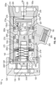
FIG. 4a is a side view of the cross section of the faucet, with faucet in a closed state; -
FIG. 4b shows a stub shaft that is within the faucet; -
FIG. 5a is a side view of the cross section of the faucet, with faucet in an opened state; -
FIG. 5b shows a damper mount that is within the faucet; -
FIG. 5c shows a valve plug that is within the faucet; and -
FIG. 6 shows the push knob removed from the faucet to expose a damper adjustment nut. - The embodiments are directed to a faucet 100 (
FIG. 1 ) having apush knob 120 that is pushed inwardly, from a first position or forward position (FIG. 4 ) to a second position or aft position (FIG. 5 ), to move an internal piston 130 (FIG. 3 ) aft within thefaucet 100 and open thefaucet 100. Thepush knob 120 andpiston 130, together, are biased outwardly, e.g., by aspring 140, from the second position to the first position, to close thefaucet 100. A linear damper (or damper) 135 is fixed within thefaucet 100, between thepush knob 120 and thepiston 130, and controls the movement of thepiston 130 from the second position to the first position, to thereby control closing of thefaucet 100. - Turing to
FIGS. 1-2 , additional details about thefaucet 100 are disclosed. Thefaucet 100 extends from forward toaft ends aft end 100a of thefaucet 100 includes abackplate 150 and forward andaft gaskets backplate 150. Thebackplate 150 defines first andsecond apertures terminal ends second feed lines backplate 150 is mountable to an exterior structure, such as a structure of an aircraft. O-rings terminal ends faucet outlet 180 is located between the forward and aft ends 100f, 100a. Drain bleedplugs aft end 100a of thefaucet 100 for draining thefeed lines push knob 120 may have temperature control indicia 120t for modulating the outflow between hot and cold flows. - Turning to
FIGS. 3-4a thefaucet 100 includes abody 200 that extends from aforward end 200f to anaft end 200a. Theaft end 200a of thebody 200 includes anaft wall 210 that defines faucet inlet ports 220 (one shown) that are configured to receive flow from thefeed lines bleed plugs aft wall 210. Forward of theaft end 200a, thebody 200 is hollow to define abody cavity 200c. Thefaucet outlet 180 is defined between the forward andaft ends aeration plug 250 is secured to thefaucet outlet 180. An o-ring 260 is disposed at an inner side 250a of theaeration plug 250. Afilter disk 265 is between the o-ring 260 and theaeration plug 250. - The
faucet 100 includes acartridge 270 that extends from aforward end 270f to anaft end 270a and is hollow to define acartridge cavity 270c. Thecartridge 270 is disposed within thebody cavity 200c, against theaft wall 210 of thebody 200. Thecartridge 270 defines acartridge inlet port 270i and acartridge outlet port 270p, both being sidewall ports extending radially though thecartridge 270. With these ports, thecartridge cavity 270c of thecartridge 270 defines a flow path through thefaucet 100, between thefaucet inlet ports 220 and thefaucet outlet 180. Forward and aft outer ring seals 280f, 280a, or wiper seals, are disposed between thecartridge 270 and thebody 200, forward and aft of thecartridge outlet port 270p. Thecartridge 270 defines forward and aft o-ring grooves body 200 and are forward and aft of thecartridge outlet port 270p to seat the outer ring seals 280f, 280a. Theaft groove 274a is between thecartridge outlet port 270p and thecartridge inlet port 270i. A cartridge aft sealseat 275 is provided in thecartridge cavity 270c and located between the cartridge inlet andoutlet ports seat 275 are discussed below. - The
faucet 100 includes apiston 130 extending from aforward end 130f to anaft end 130a. Thepiston 130 is seated within thecartridge cavity 270c. Thepiston 130 includes a forward piston cavity 130c1 and an aft piston cavity 130c2 that are separate from each other, and anaft seal lip 295 that seats an o-ring 297. That is, aninner wall 130w separates the piston cavities 130c1, 130c2, and theinner wall 130w is located at an intermediate position along thepiston 130. Theforward end 130f of thepiston 130 is forward of theforward end 270f of thecartridge 270 and aft of theforward end 200f of thebody 200. Aninner ring seal 299, or wiper seal, is disposed between thecartridge 270 and thepiston 130, forward of thecartridge outlet port 270p. Thecartridge 270 defines an inner-facing forward o-ring groove 274i that faces thepiston 130 and is between theforward end 270f of thecartridge 270 and thecartridge outlet port 270p. Thepiston 130 is configured to move within the cartridge between a first position (FIG. 4a ), when the o-ring 297 is against the cartridge aft sealseat 275 and thefaucet 100 is closed, and a second position (FIG. 5a ), when the o-ring 297 away from the cartridge aft sealseat 275 and thefaucet 100 is opened. That is, fluid 90 can flow into thecartridge inlet port 270i and into thecartridge cavity 270c when thefaucet 100 is closed, but the fluid cannot flow past the o-ring 297 and flow to thecartridge outlet port 270p. This prevents flow from leaving thefaucet 100. In comparison, as shown inFIG. 5a , when thepiston 130 is in the second position, the o-ring 297 is spaced apart from the cartridge aft sealseat 275 in thecartridge cavity 270c, and the flow path via thecartridge 270 is unsealed.Fluid 90 can flow around thepiston 130 and through thefaucet outlet 180. - The
push knob 120 is cup shaped and seated around theforward end 200f of thebody 200. Thepush knob 120 is fixed to thepiston 130, as discussed in greater detail below, and moves thepiston 130 between the first position and the second position. In the first position (FIG. 4a ), aninner surface 120i of thepush knob 120 is spaced apart from theforward end 200f of thebody 200. In the second position (FIG. 5a ), theinner surface 120i of thepush knob 120 is adjacent to or against theforward end 200f of thebody 200. - A stub shaft 310 (also shown in
FIG. 4b ) extends from a forward end 3 10f to anaft end 310a. Theaft end 310a of thestub shaft 310 defines aring portion 315 that is keyed to receive theforward end 130f of thepiston 130. As such, theforward end 200f of thepiston 130 may have a non-circular cross section. Theforward end 310f of thestub shaft 310 is connected to a forward ring 320 (also shown inFIG. 6 ), which is connected to theinner surface 120i of thepush knob 120. Theinner surface 120i of thepush knob 120 is keyed to receive theforward ring 320. As such, at least aportion 320p (FIG. 6 ) of theforward ring 320 may have a non-circular shape. From this configuration, turning thepush knob 120 turns thepiston 130 to modulate the flow temperature as discussed in greater detail below. - The
compression spring 140, which may be a wave spring, extends from theaft end 310a of thestub shaft 310 to theforward end 270f of thecartridge 270 to bias thestub shaft 310 and pushknob 120 from the second position toward the first position. A c-clip 340 is disposed around theforward end 270f of thepiston 130, forward of theaft end 310a of thestub shaft 310. With the c-clip 340, movement of thestub shaft 310 from the second position to the first position moves thepiston 130 from the second position to the first position. - Turning to
FIGS. 3 and5a , thedamper 135 extends from aforward end 135f to anaft end 135a. Thedamper 135 extends into the forward piston cavity 130c1 of thepiston 130. Aplunger 360 extends aft from theaft end 135a of thedamper 135. Thedamper 135 may be a solenoid, electrically powered, or may be hydraulic. - A
damper mount 370 is fixed within theforward end 200f of thebody 200, forward of thecartridge 270, e.g. via aset screw 371. Thedamper mount 370 extends from aforward end 370f to anaft end 370a, is cup shaped to define a base 380 (FIG. 5b ) at theforward end 370f and acylinder portion 390 that extends to theaft end 370a. Thebase 380 defines acenter aperture 400 that is threaded for engaging theforward end 135f of thedamper 135. Thedamper 135 is fixed within thefaucet 100 via thedamper mount 370. With this configuration, theplunger 360 engages thepiston 130 and dampens linear motion of thepiston 130 moving between the second and first positions. - A
locknut 410 is threaded to theforward end 135f of thedamper 135, against thebase 380 of thedamper mount 370. Thelocknut 410 may be engaged by removing the push knob 120 (FIG. 6 ). Adjusting thelocknut 410 shifts thedamper 135 forward or aft to adjust loading on thedamper plunger 360. - A forward c-
clip 420 is located at theforward end 200f of thebody 200, forward of thedamper mount 370. The forward c-clip 420 prevents thedamper mount 370 from moving forward of theforward end 200f of thebody 200. Abushing 430 that may be plastic is located between the forward c-clip 420 and thedamper mount 370. - The
aft end 370a of thedamper mount 370 is spaced apart from theforward end 270f of thecartridge 270. Anouter compression spring 440 that may be a wave spring is disposed betweendamper mount 370 and thecartridge 270. Thespring 440 biases thecartridge 270 against theaft wall 210 of thebody 200. Anaft bushing 450 that may be bronze is located between theouter spring 440 and thecartridge 270. - The
base 380 of thedamper mount 370 defines circumferential apertures 402 (FIG. 5b ) that are spaced apart from thecenter aperture 400 and each other. Thestub shaft 310 defines leg portions 317 (FIG. 4b ) extending forward of thering portion 315 and are circumferentially spaced apart from each other. Theleg portions 317 extend through thecircumferential apertures 402 to engage theforward ring 320. That is, theforward ring 320 is connected to theleg portions 317 of thestub shaft 310 at theforward end 310f of thestub shaft 310. Theforward ring 320 is releasably connected to thepush knob 120. Thepush knob 120 is released from theforward ring 320 to remove thepush knob 120 from thebody 200. Aset screw 470 may enable attaching and removing thepush knob 120 to provide access to thelocknut 410 for adjusting thedamper 135. - A
valve plug 480 is disposed against theaft wall 210, within thebody cavity 200c, to define aplug base 482 and plugbody 484 that extends into thecartridge cavity 270c. Thevalve plug 480 includes a forward stem 485 (FIG. 5C ) that extends into the aft piston cavity 130c2. The aft piston cavity 130c2 and forward stem 485 are shaped in a such that rotation of thepiston 130, from rotation of thepush knob 120, rotates thevalve plug 480. For example, thestem 485 may be shaped as a thin rectangular block. A shape of theplug base 482 is non-circular and may have rotation stops 486 (FIG. 5C ). With this configuration, rotation of the valve plug changes a relative flow area from thefeed lines FIG. 2 ) into thefaucet 100, to modulate the flow temperature. A plug o-ring 490 is located around thevalve plug body 484, between theplug base 482 and thestem 485, to prevent flow around thevalve plug 480. Theplug body 484 may define an outer o-ring groove 487 that faces thecartridge 270 and seats the plug o-ring 490. - As shown in
FIGS. 3 ,5a and6 , anouter cover 500 may secured around thebody 200. Theouter cover 500 may form acutout 510 to position theouter cover 500 around thefaucet outlet 180. - The above disclosed
faucet 100 provides for access to alocknut 410 for adjustment of thedamper 135. The design isolates thedamper 135 from thewater path 90 so that thedamper 135 may be replaced and interchanged with another damper if there is a timing requirement outside of an adjustment range for an installed damper. The damper adjustment may be performed while thefaucet 100 is connected to awater supply lines damper 135 may be replaced with an electronic solenoid to provide electronic faucet functions. - Benefits of the disclosed
faucet 100 is that only thepush knob 120 needs to be removed to adjust thedamper 135. Thedamper 135 is isolated from thewater path 90 within thefaucet 100. As a result, if damping fluid within thedamper 135 were to leak, or any part thedamper 135 were to break, thewater 90 through thefaucet 100 would not become contaminated. The damper may be able to be replaced for different timing and tuning. The damper is able to be adjusted without removing major components of the faucet body in the water flow path. The damper is able to be replaced as an electronic solenoid. In addition, thefaucet 100 is capable of being drained by removingdrain bleed plugs - The terminology used herein is for the purpose of describing particular embodiments only and is not intended to be limiting of the present disclosure. As used herein, the singular forms "a", "an" and "the" are intended to include the plural forms as well, unless the context clearly indicates otherwise. It will be further understood that the terms "comprises" and/or "comprising," when used in this specification, specify the presence of stated features, integers, steps, operations, elements, and/or components, but do not preclude the presence or addition of one or more other features, integers, steps, operations, element components, and/or groups thereof.
- Those of skill in the art will appreciate that various example embodiments are shown and described herein, each having certain features in the particular embodiments, but the present disclosure is not thus limited. Rather, the present disclosure can be modified to incorporate any number of variations, alterations, substitutions, combinations, sub-combinations, or equivalent arrangements not heretofore described, but which are commensurate with the scope of the present disclosure. Additionally, while various embodiments of the present disclosure have been described, it is to be understood that aspects of the present disclosure may include only some of the described embodiments. Accordingly, the present disclosure is not to be seen as limited by the foregoing description, but is only limited by the scope of the appended claims.
Claims (15)
- A faucet comprising:a body (200), extending from a forward end to an aft end to define a body cavity, wherein the body (200) includes an aft wall that defines faucet inlet ports, and the body (200) defines a faucet outlet between the forward and aft ends;a push knob (120), operationally coupled to the forward end of the body (200);a cartridge (270), fixed within the body cavity, wherein the cartridge (270) defines a cartridge cavity that has an aft seal seat, a cartridge outlet port that is forward of the aft seal seat, and a cartridge inlet port that is aft of the aft seal seat;a piston (130) that is seated within the cartridge cavity, the piston (130) defining an aft seal lip, wherein:the piston (130) is movable by the push knob (120) from a first position to a second position, to move the lip away from the seal seat and open the faucet; andthe piston (130) is movable by a spring from the second position to the first position, to position the lip against the aft seal seat and close the faucet; anda linear damper (135), mounted to the forward end of the body (200), wherein the linear damper (135) engages the piston (130) to dampen movement of the piston (130) from the second position to the first position.
- The faucet of claim 1, wherein the aft seal lip defines an aft seal seat.
- The faucet of claim 1 or 2, wherein:the cartridge (270) extends from an aft end to a forward end, the aft end of the cartridge (270) is aft of the faucet outlet and the forward end of the cartridge (270) is forward of the faucet outlet; andthe cartridge (270) defines: an aft seal seat that faces the body (200) is between the aft end of the cartridge (270) and the cartridge outlet port; and a forward o-ring groove that faces the body (200) is between the forward end of the cartridge (270) and the cartridge outlet port.
- The faucet of any preceding claim, wherein:the piston (130) extends from an aft end that defines the aft seal lip to a forward end that extends forward of the forward end of the cartridge (270); andthe cartridge (270) defines an inner-facing forward o-ring groove that faces the piston (130) and is between the forward end of the cartridge (270) and the cartridge outlet port.
- The faucet of any preceding claim, wherein:the forward end of the piston (130) defines a forward piston cavity that extends aft to a location that is intermediate the forward and aft ends of the piston (130); andthe linear damper (135) extends from a forward end that extends forward of the forward end of the body (200) to an aft end that extends into the forward piston cavity, and the damper includes a plunger extending aft from the aft end of the damper to engage the piston (130).
- The faucet of claim 5, wherein:the forward end of the piston (130) is non-circular; andthe faucet includes a stub shaft extending between: a forward end that is connected to the push knob (120); and an aft end that defines a ring portion having an inner surface that is shaped to receive the forward end of the piston (130), whereby pushing the push knob (120) moves the piston (130), and turning the push knob (120) turns the piston (130).
- The faucet of claim 6, further comprising:
a compression spring that extends from the aft end of the stub shaft to the forward end of the cartridge (270) to bias the stub shaft and the push knob (120) toward the first position, and/or further comprising:
a c-clip that is disposed on the piston (130), forward of the aft end of the stub shaft, whereby movement of the stub shaft from the second position to the first position moves the piston (130) from the second position to the first position. - The faucet of claim 6, wherein:the damper extends from a forward end to an aft end, and the forward end of the damper is threaded; andthe faucet further includes a cup shaped damper mount that defines: a forward base having a center threaded aperture for engaging the forward end of the damper; and a cylindrical wall extending aft from the forward base, wherein the cylindrical wall is fixed to the forward end of the body (200), forward of the cartridge (270).
- The faucet of claim 8, further comprising:
a locknut, threaded to the forward end of the damper, against the damper mount, wherein adjusting the locknut shifts the damper forward or aft within the faucet to adjust loading on the plunger of the damper and optionally wherein:the base of the damper mount defines apertures, and the stub shaft defines legs that are spaced apart from each other and extend forward from the ring portion, through the apertures in the damper mount; andthe faucet includes a forward ring connected to the legs of the stub shaft and the push knob (120), wherein the push knob (120) is released from the forward ring to remove the push knob (120) from the body (200), to thereby provide access to the locknut. - The faucet of claim 8, further comprising:a forward c-clip fixed at the forward end of the body (200), forward of the damper mount, and a forward bushing is between the forward c-clip and the damper mount, anda wave spring extending aft from the damper mount, and a bushing between the wave spring and the forward end of the cartridge (270), whereby the cartridge (270) is biased against the aft wall of the body (200).
- The faucet of claim 5, wherein:
the faucet further comprises a valve plug disposed against the aft wall of the body (200) and extending into the cartridge cavity, wherein rotating the piston (130), via rotating the push knob (120), rotates the valve plug, to modulate flow between the faucet inlet ports. - The faucet of claim 11, wherein:the valve plug includes a forward stem; andthe aft end of the piston (130) defines an aft piston cavity that is fluidly separated from the forward piston cavity, and the stem of the valve plug extends into the aft piston cavity,wherein the aft piston cavity and the stem are shaped such that rotation of the piston (130) rotates the valve plug, and optionally wherein:
the valve plug defines a plug base and a plug body between the plug base and the stem, wherein the plug body is within the cartridge cavity, and defines an outer o-ring groove that faces the cartridge (270). - The faucet of any preceding claim, further comprising:
an aeration plug that is secured to the faucet outlet, and/or . further comprising:
a bleed plug disposed within the aft wall that is fluidly coupled to the faucet inlet ports and removable from the aft wall to bleed the faucet inlet ports. - The faucet of any preceding claim, wherein:the aft end of the body (200) includes:a backplate; andforward and aft gaskets that are forward and aft of the backplate,wherein:the backplate defines first and second apertures for receiving terminal ends of feed lines that are connected to the faucet inlet ports; andthe backplate is mountable between the aft wall of the body (200) and an exterior structure, and/or whereinthe damper is a solenoid or mechanically adjustable.
- The faucet of any preceding claim, further comprising:
an outer cover is secured to the body (200), the outer cover defines a cutout to position the outer cover around the faucet outlet.
Applications Claiming Priority (1)
| Application Number | Priority Date | Filing Date | Title |
|---|---|---|---|
| US202363483810P | 2023-02-08 | 2023-02-08 |
Publications (1)
| Publication Number | Publication Date |
|---|---|
| EP4414588A1 true EP4414588A1 (en) | 2024-08-14 |
Family
ID=89854434
Family Applications (1)
| Application Number | Title | Priority Date | Filing Date |
|---|---|---|---|
| EP24156393.1A Pending EP4414588A1 (en) | 2023-02-08 | 2024-02-07 | Faucet with internal damper |
Country Status (4)
| Country | Link |
|---|---|
| US (1) | US12297919B2 (en) |
| EP (1) | EP4414588A1 (en) |
| CN (1) | CN118462856A (en) |
| CA (1) | CA3225675A1 (en) |
Citations (6)
| Publication number | Priority date | Publication date | Assignee | Title |
|---|---|---|---|---|
| DE7212321U (en) * | 1971-03-30 | 1972-06-29 | Knapp A | FLUID DOSING VALVE |
| FR2120893A5 (en) * | 1971-01-09 | 1972-08-18 | Knapp Alfons | |
| FR2509007A1 (en) * | 1981-07-03 | 1983-01-07 | Presto Robinets Sa | TAP HEAD, COMPRISING A TIMING DEVICE, ADAPTABLE TO BASES RECEIVING ORDINARY HEADS |
| US4457452A (en) * | 1982-05-24 | 1984-07-03 | Symmons Industries, Inc. | Automatic shut-off valve |
| EP2998622A1 (en) * | 2014-09-17 | 2016-03-23 | Franke Aquarotter GmbH | Valve cartridge for a sanitary fitting |
| EP4043764A1 (en) * | 2021-02-10 | 2022-08-17 | B/E Aerospace, Inc. | Self closing taps |
Family Cites Families (6)
| Publication number | Priority date | Publication date | Assignee | Title |
|---|---|---|---|---|
| DE4323063A1 (en) | 1993-07-10 | 1995-01-12 | Grohe Armaturen Friedrich | Self-closing valve |
| US5771923A (en) * | 1996-04-22 | 1998-06-30 | Speakman Company | Gasketing and bleed means for an electrically controlled faucet assembly |
| US6286533B1 (en) | 1997-09-19 | 2001-09-11 | Mark Controls Corporation | Metering valve assembly |
| US7533683B2 (en) * | 2007-01-09 | 2009-05-19 | Newfrey Llc | Cartridge underbody attachment |
| US8555922B2 (en) | 2007-08-16 | 2013-10-15 | Zurn Industries, Llc | Metering mixing faucet |
| FR2991744B1 (en) | 2012-06-11 | 2014-09-12 | Delabie | TEMPORIZED MIXING TAP WITH MODULATING FLOW TIME |
-
2023
- 2023-08-02 US US18/363,905 patent/US12297919B2/en active Active
-
2024
- 2024-01-05 CN CN202410026686.5A patent/CN118462856A/en active Pending
- 2024-01-10 CA CA3225675A patent/CA3225675A1/en active Pending
- 2024-02-07 EP EP24156393.1A patent/EP4414588A1/en active Pending
Patent Citations (6)
| Publication number | Priority date | Publication date | Assignee | Title |
|---|---|---|---|---|
| FR2120893A5 (en) * | 1971-01-09 | 1972-08-18 | Knapp Alfons | |
| DE7212321U (en) * | 1971-03-30 | 1972-06-29 | Knapp A | FLUID DOSING VALVE |
| FR2509007A1 (en) * | 1981-07-03 | 1983-01-07 | Presto Robinets Sa | TAP HEAD, COMPRISING A TIMING DEVICE, ADAPTABLE TO BASES RECEIVING ORDINARY HEADS |
| US4457452A (en) * | 1982-05-24 | 1984-07-03 | Symmons Industries, Inc. | Automatic shut-off valve |
| EP2998622A1 (en) * | 2014-09-17 | 2016-03-23 | Franke Aquarotter GmbH | Valve cartridge for a sanitary fitting |
| EP4043764A1 (en) * | 2021-02-10 | 2022-08-17 | B/E Aerospace, Inc. | Self closing taps |
Also Published As
| Publication number | Publication date |
|---|---|
| US12297919B2 (en) | 2025-05-13 |
| CN118462856A (en) | 2024-08-09 |
| CA3225675A1 (en) | 2025-04-15 |
| US20240263713A1 (en) | 2024-08-08 |
Similar Documents
| Publication | Publication Date | Title |
|---|---|---|
| US8146549B2 (en) | Feeder for a camshaft adjuster | |
| CA2062994C (en) | Thermostatically controlled mixing valve | |
| US6227246B1 (en) | Faucet mixing valve housing with check valves and filter | |
| US4250912A (en) | Cartridge faucet for hydraulic systems | |
| EP3018307B1 (en) | Camshaft phaser | |
| LU100957B1 (en) | Gas pressure reducer with cam commanded shut-off valve | |
| CN210128105U (en) | Valve body modular system and poppet valve | |
| CA2452809C (en) | Diaphragm valve having adjustable closure means | |
| WO2005054969A2 (en) | Compressed natural gas pressure regulator | |
| US5477885A (en) | Flow rate and temperature limiting mechanism for a mixing valve | |
| PL176598B1 (en) | Thermostatic mixing device | |
| US4753418A (en) | Non-rise faucet assembly having stem locator cap to insure proper sealing | |
| US2819868A (en) | Ball valve having adjustable seat unit | |
| US4739793A (en) | Thermostatically operated valve | |
| US12297919B2 (en) | Faucet with internal damper | |
| EP4043764B1 (en) | Self closing taps | |
| WO1996000358A1 (en) | Sweep flow valve with removable valve seat | |
| US3490735A (en) | Packed stem valve | |
| US6311948B1 (en) | Fluid valve assembly | |
| EP4325098B1 (en) | Mechanical faucet utilizing hydraulic dampers for timing | |
| EP0077506B1 (en) | Fluid control valve | |
| JPS6052343B2 (en) | fluid valve | |
| JP3750008B2 (en) | Multi-function flow control faucet | |
| EP0168630A1 (en) | Faucet valve with check stop | |
| GB2081843A (en) | Fluid valve means |
Legal Events
| Date | Code | Title | Description |
|---|---|---|---|
| PUAI | Public reference made under article 153(3) epc to a published international application that has entered the european phase |
Free format text: ORIGINAL CODE: 0009012 |
|
| STAA | Information on the status of an ep patent application or granted ep patent |
Free format text: STATUS: THE APPLICATION HAS BEEN PUBLISHED |
|
| AK | Designated contracting states |
Kind code of ref document: A1 Designated state(s): AL AT BE BG CH CY CZ DE DK EE ES FI FR GB GR HR HU IE IS IT LI LT LU LV MC ME MK MT NL NO PL PT RO RS SE SI SK SM TR |
|
| STAA | Information on the status of an ep patent application or granted ep patent |
Free format text: STATUS: REQUEST FOR EXAMINATION WAS MADE |
|
| 17P | Request for examination filed |
Effective date: 20250213 |
|
| GRAP | Despatch of communication of intention to grant a patent |
Free format text: ORIGINAL CODE: EPIDOSNIGR1 |
|
| STAA | Information on the status of an ep patent application or granted ep patent |
Free format text: STATUS: GRANT OF PATENT IS INTENDED |
|
| RIC1 | Information provided on ipc code assigned before grant |
Ipc: F16K 11/074 20060101AFI20251217BHEP Ipc: F16K 21/10 20060101ALI20251217BHEP |
|
| INTG | Intention to grant announced |
Effective date: 20260109 |
|
| GRAS | Grant fee paid |
Free format text: ORIGINAL CODE: EPIDOSNIGR3 |
|
| GRAA | (expected) grant |
Free format text: ORIGINAL CODE: 0009210 |
|
| STAA | Information on the status of an ep patent application or granted ep patent |
Free format text: STATUS: THE PATENT HAS BEEN GRANTED |