EP4414577A1 - Thrust bearing assembly - Google Patents
Thrust bearing assembly Download PDFInfo
- Publication number
- EP4414577A1 EP4414577A1 EP24157200.7A EP24157200A EP4414577A1 EP 4414577 A1 EP4414577 A1 EP 4414577A1 EP 24157200 A EP24157200 A EP 24157200A EP 4414577 A1 EP4414577 A1 EP 4414577A1
- Authority
- EP
- European Patent Office
- Prior art keywords
- oil
- thrust pad
- thrust
- pad assembly
- machining
- Prior art date
- Legal status (The legal status is an assumption and is not a legal conclusion. Google has not performed a legal analysis and makes no representation as to the accuracy of the status listed.)
- Pending
Links
Images



Classifications
-
- F—MECHANICAL ENGINEERING; LIGHTING; HEATING; WEAPONS; BLASTING
- F16—ENGINEERING ELEMENTS AND UNITS; GENERAL MEASURES FOR PRODUCING AND MAINTAINING EFFECTIVE FUNCTIONING OF MACHINES OR INSTALLATIONS; THERMAL INSULATION IN GENERAL
- F16C—SHAFTS; FLEXIBLE SHAFTS; ELEMENTS OR CRANKSHAFT MECHANISMS; ROTARY BODIES OTHER THAN GEARING ELEMENTS; BEARINGS
- F16C33/00—Parts of bearings; Special methods for making bearings or parts thereof
- F16C33/02—Parts of sliding-contact bearings
- F16C33/04—Brasses; Bushes; Linings
- F16C33/06—Sliding surface mainly made of metal
- F16C33/10—Construction relative to lubrication
- F16C33/1025—Construction relative to lubrication with liquid, e.g. oil, as lubricant
- F16C33/106—Details of distribution or circulation inside the bearings, e.g. details of the bearing surfaces to affect flow or pressure of the liquid
- F16C33/1085—Channels or passages to recirculate the liquid in the bearing
-
- F—MECHANICAL ENGINEERING; LIGHTING; HEATING; WEAPONS; BLASTING
- F01—MACHINES OR ENGINES IN GENERAL; ENGINE PLANTS IN GENERAL; STEAM ENGINES
- F01D—NON-POSITIVE DISPLACEMENT MACHINES OR ENGINES, e.g. STEAM TURBINES
- F01D25/00—Component parts, details, or accessories, not provided for in, or of interest apart from, other groups
- F01D25/16—Arrangement of bearings; Supporting or mounting bearings in casings
- F01D25/166—Sliding contact bearing
- F01D25/168—Sliding contact bearing for axial load mainly
-
- F—MECHANICAL ENGINEERING; LIGHTING; HEATING; WEAPONS; BLASTING
- F01—MACHINES OR ENGINES IN GENERAL; ENGINE PLANTS IN GENERAL; STEAM ENGINES
- F01D—NON-POSITIVE DISPLACEMENT MACHINES OR ENGINES, e.g. STEAM TURBINES
- F01D25/00—Component parts, details, or accessories, not provided for in, or of interest apart from, other groups
- F01D25/16—Arrangement of bearings; Supporting or mounting bearings in casings
-
- F—MECHANICAL ENGINEERING; LIGHTING; HEATING; WEAPONS; BLASTING
- F01—MACHINES OR ENGINES IN GENERAL; ENGINE PLANTS IN GENERAL; STEAM ENGINES
- F01D—NON-POSITIVE DISPLACEMENT MACHINES OR ENGINES, e.g. STEAM TURBINES
- F01D25/00—Component parts, details, or accessories, not provided for in, or of interest apart from, other groups
- F01D25/18—Lubricating arrangements
-
- F—MECHANICAL ENGINEERING; LIGHTING; HEATING; WEAPONS; BLASTING
- F02—COMBUSTION ENGINES; HOT-GAS OR COMBUSTION-PRODUCT ENGINE PLANTS
- F02C—GAS-TURBINE PLANTS; AIR INTAKES FOR JET-PROPULSION PLANTS; CONTROLLING FUEL SUPPLY IN AIR-BREATHING JET-PROPULSION PLANTS
- F02C7/00—Features, components parts, details or accessories, not provided for in, or of interest apart form groups F02C1/00 - F02C6/00; Air intakes for jet-propulsion plants
- F02C7/06—Arrangements of bearings; Lubricating
-
- F—MECHANICAL ENGINEERING; LIGHTING; HEATING; WEAPONS; BLASTING
- F16—ENGINEERING ELEMENTS AND UNITS; GENERAL MEASURES FOR PRODUCING AND MAINTAINING EFFECTIVE FUNCTIONING OF MACHINES OR INSTALLATIONS; THERMAL INSULATION IN GENERAL
- F16C—SHAFTS; FLEXIBLE SHAFTS; ELEMENTS OR CRANKSHAFT MECHANISMS; ROTARY BODIES OTHER THAN GEARING ELEMENTS; BEARINGS
- F16C17/00—Sliding-contact bearings for exclusively rotary movement
- F16C17/04—Sliding-contact bearings for exclusively rotary movement for axial load only
-
- F—MECHANICAL ENGINEERING; LIGHTING; HEATING; WEAPONS; BLASTING
- F16—ENGINEERING ELEMENTS AND UNITS; GENERAL MEASURES FOR PRODUCING AND MAINTAINING EFFECTIVE FUNCTIONING OF MACHINES OR INSTALLATIONS; THERMAL INSULATION IN GENERAL
- F16C—SHAFTS; FLEXIBLE SHAFTS; ELEMENTS OR CRANKSHAFT MECHANISMS; ROTARY BODIES OTHER THAN GEARING ELEMENTS; BEARINGS
- F16C17/00—Sliding-contact bearings for exclusively rotary movement
- F16C17/04—Sliding-contact bearings for exclusively rotary movement for axial load only
- F16C17/06—Sliding-contact bearings for exclusively rotary movement for axial load only with tiltably-supported segments, e.g. Michell bearings
-
- F—MECHANICAL ENGINEERING; LIGHTING; HEATING; WEAPONS; BLASTING
- F16—ENGINEERING ELEMENTS AND UNITS; GENERAL MEASURES FOR PRODUCING AND MAINTAINING EFFECTIVE FUNCTIONING OF MACHINES OR INSTALLATIONS; THERMAL INSULATION IN GENERAL
- F16C—SHAFTS; FLEXIBLE SHAFTS; ELEMENTS OR CRANKSHAFT MECHANISMS; ROTARY BODIES OTHER THAN GEARING ELEMENTS; BEARINGS
- F16C33/00—Parts of bearings; Special methods for making bearings or parts thereof
- F16C33/02—Parts of sliding-contact bearings
- F16C33/04—Brasses; Bushes; Linings
- F16C33/06—Sliding surface mainly made of metal
- F16C33/10—Construction relative to lubrication
- F16C33/1025—Construction relative to lubrication with liquid, e.g. oil, as lubricant
- F16C33/106—Details of distribution or circulation inside the bearings, e.g. details of the bearing surfaces to affect flow or pressure of the liquid
-
- F—MECHANICAL ENGINEERING; LIGHTING; HEATING; WEAPONS; BLASTING
- F16—ENGINEERING ELEMENTS AND UNITS; GENERAL MEASURES FOR PRODUCING AND MAINTAINING EFFECTIVE FUNCTIONING OF MACHINES OR INSTALLATIONS; THERMAL INSULATION IN GENERAL
- F16C—SHAFTS; FLEXIBLE SHAFTS; ELEMENTS OR CRANKSHAFT MECHANISMS; ROTARY BODIES OTHER THAN GEARING ELEMENTS; BEARINGS
- F16C33/00—Parts of bearings; Special methods for making bearings or parts thereof
- F16C33/02—Parts of sliding-contact bearings
- F16C33/04—Brasses; Bushes; Linings
- F16C33/06—Sliding surface mainly made of metal
- F16C33/10—Construction relative to lubrication
- F16C33/1025—Construction relative to lubrication with liquid, e.g. oil, as lubricant
- F16C33/106—Details of distribution or circulation inside the bearings, e.g. details of the bearing surfaces to affect flow or pressure of the liquid
- F16C33/1065—Grooves on a bearing surface for distributing or collecting the liquid
-
- F—MECHANICAL ENGINEERING; LIGHTING; HEATING; WEAPONS; BLASTING
- F16—ENGINEERING ELEMENTS AND UNITS; GENERAL MEASURES FOR PRODUCING AND MAINTAINING EFFECTIVE FUNCTIONING OF MACHINES OR INSTALLATIONS; THERMAL INSULATION IN GENERAL
- F16C—SHAFTS; FLEXIBLE SHAFTS; ELEMENTS OR CRANKSHAFT MECHANISMS; ROTARY BODIES OTHER THAN GEARING ELEMENTS; BEARINGS
- F16C33/00—Parts of bearings; Special methods for making bearings or parts thereof
- F16C33/02—Parts of sliding-contact bearings
- F16C33/04—Brasses; Bushes; Linings
- F16C33/06—Sliding surface mainly made of metal
- F16C33/10—Construction relative to lubrication
- F16C33/1025—Construction relative to lubrication with liquid, e.g. oil, as lubricant
- F16C33/106—Details of distribution or circulation inside the bearings, e.g. details of the bearing surfaces to affect flow or pressure of the liquid
- F16C33/108—Details of distribution or circulation inside the bearings, e.g. details of the bearing surfaces to affect flow or pressure of the liquid with a plurality of elements forming the bearing surfaces, e.g. bearing pads
-
- F—MECHANICAL ENGINEERING; LIGHTING; HEATING; WEAPONS; BLASTING
- F16—ENGINEERING ELEMENTS AND UNITS; GENERAL MEASURES FOR PRODUCING AND MAINTAINING EFFECTIVE FUNCTIONING OF MACHINES OR INSTALLATIONS; THERMAL INSULATION IN GENERAL
- F16C—SHAFTS; FLEXIBLE SHAFTS; ELEMENTS OR CRANKSHAFT MECHANISMS; ROTARY BODIES OTHER THAN GEARING ELEMENTS; BEARINGS
- F16C33/00—Parts of bearings; Special methods for making bearings or parts thereof
- F16C33/02—Parts of sliding-contact bearings
- F16C33/04—Brasses; Bushes; Linings
- F16C33/20—Sliding surface consisting mainly of plastics
- F16C33/203—Multilayer structures, e.g. sleeves comprising a plastic lining
- F16C33/205—Multilayer structures, e.g. sleeves comprising a plastic lining with two layers
-
- F—MECHANICAL ENGINEERING; LIGHTING; HEATING; WEAPONS; BLASTING
- F16—ENGINEERING ELEMENTS AND UNITS; GENERAL MEASURES FOR PRODUCING AND MAINTAINING EFFECTIVE FUNCTIONING OF MACHINES OR INSTALLATIONS; THERMAL INSULATION IN GENERAL
- F16N—LUBRICATING
- F16N1/00—Constructional modifications of parts of machines or apparatus for the purpose of lubrication
-
- F—MECHANICAL ENGINEERING; LIGHTING; HEATING; WEAPONS; BLASTING
- F01—MACHINES OR ENGINES IN GENERAL; ENGINE PLANTS IN GENERAL; STEAM ENGINES
- F01D—NON-POSITIVE DISPLACEMENT MACHINES OR ENGINES, e.g. STEAM TURBINES
- F01D21/00—Shutting-down of machines or engines, e.g. in emergency; Regulating, controlling, or safety means not otherwise provided for
- F01D21/003—Arrangements for testing or measuring
-
- F—MECHANICAL ENGINEERING; LIGHTING; HEATING; WEAPONS; BLASTING
- F01—MACHINES OR ENGINES IN GENERAL; ENGINE PLANTS IN GENERAL; STEAM ENGINES
- F01D—NON-POSITIVE DISPLACEMENT MACHINES OR ENGINES, e.g. STEAM TURBINES
- F01D21/00—Shutting-down of machines or engines, e.g. in emergency; Regulating, controlling, or safety means not otherwise provided for
- F01D21/12—Shutting-down of machines or engines, e.g. in emergency; Regulating, controlling, or safety means not otherwise provided for responsive to temperature
-
- F—MECHANICAL ENGINEERING; LIGHTING; HEATING; WEAPONS; BLASTING
- F05—INDEXING SCHEMES RELATING TO ENGINES OR PUMPS IN VARIOUS SUBCLASSES OF CLASSES F01-F04
- F05D—INDEXING SCHEME FOR ASPECTS RELATING TO NON-POSITIVE-DISPLACEMENT MACHINES OR ENGINES, GAS-TURBINES OR JET-PROPULSION PLANTS
- F05D2240/00—Components
- F05D2240/50—Bearings
- F05D2240/52—Axial thrust bearings
-
- F—MECHANICAL ENGINEERING; LIGHTING; HEATING; WEAPONS; BLASTING
- F05—INDEXING SCHEMES RELATING TO ENGINES OR PUMPS IN VARIOUS SUBCLASSES OF CLASSES F01-F04
- F05D—INDEXING SCHEME FOR ASPECTS RELATING TO NON-POSITIVE-DISPLACEMENT MACHINES OR ENGINES, GAS-TURBINES OR JET-PROPULSION PLANTS
- F05D2260/00—Function
- F05D2260/98—Lubrication
-
- F—MECHANICAL ENGINEERING; LIGHTING; HEATING; WEAPONS; BLASTING
- F16—ENGINEERING ELEMENTS AND UNITS; GENERAL MEASURES FOR PRODUCING AND MAINTAINING EFFECTIVE FUNCTIONING OF MACHINES OR INSTALLATIONS; THERMAL INSULATION IN GENERAL
- F16C—SHAFTS; FLEXIBLE SHAFTS; ELEMENTS OR CRANKSHAFT MECHANISMS; ROTARY BODIES OTHER THAN GEARING ELEMENTS; BEARINGS
- F16C17/00—Sliding-contact bearings for exclusively rotary movement
- F16C17/10—Sliding-contact bearings for exclusively rotary movement for both radial and axial load
-
- F—MECHANICAL ENGINEERING; LIGHTING; HEATING; WEAPONS; BLASTING
- F16—ENGINEERING ELEMENTS AND UNITS; GENERAL MEASURES FOR PRODUCING AND MAINTAINING EFFECTIVE FUNCTIONING OF MACHINES OR INSTALLATIONS; THERMAL INSULATION IN GENERAL
- F16C—SHAFTS; FLEXIBLE SHAFTS; ELEMENTS OR CRANKSHAFT MECHANISMS; ROTARY BODIES OTHER THAN GEARING ELEMENTS; BEARINGS
- F16C2360/00—Engines or pumps
- F16C2360/23—Gas turbine engines
- F16C2360/24—Turbochargers
-
- F—MECHANICAL ENGINEERING; LIGHTING; HEATING; WEAPONS; BLASTING
- F16—ENGINEERING ELEMENTS AND UNITS; GENERAL MEASURES FOR PRODUCING AND MAINTAINING EFFECTIVE FUNCTIONING OF MACHINES OR INSTALLATIONS; THERMAL INSULATION IN GENERAL
- F16C—SHAFTS; FLEXIBLE SHAFTS; ELEMENTS OR CRANKSHAFT MECHANISMS; ROTARY BODIES OTHER THAN GEARING ELEMENTS; BEARINGS
- F16C33/00—Parts of bearings; Special methods for making bearings or parts thereof
- F16C33/02—Parts of sliding-contact bearings
- F16C33/04—Brasses; Bushes; Linings
- F16C33/20—Sliding surface consisting mainly of plastics
-
- F—MECHANICAL ENGINEERING; LIGHTING; HEATING; WEAPONS; BLASTING
- F16—ENGINEERING ELEMENTS AND UNITS; GENERAL MEASURES FOR PRODUCING AND MAINTAINING EFFECTIVE FUNCTIONING OF MACHINES OR INSTALLATIONS; THERMAL INSULATION IN GENERAL
- F16N—LUBRICATING
- F16N2210/00—Applications
- F16N2210/14—Bearings
Definitions
- the present application and the resultant patent relate generally to turbomachinery, rotating machinery, and the like and more particularly relate to a thrust bearing assembly having a number of thrust pad assemblies each with a polymer liner and a front face oil output port thereon.
- turbomachinery such as steam turbines, gas turbines, and the like, include rotor assemblies having a shaft supported by radial bearings and thrust bearings.
- the radial bearings absorb radial forces and the thrust bearings absorb axial forces.
- the bearing assemblies sustain and support these forces while permitting efficient rotation of the rotor assembly.
- the axial forces may be generated from internal pressures between the stages of the turbomachinery and the thrust therein.
- Known thrust bearing assemblies have used either radial grooves on the front face of a thrust pad that allow oil to enter and lubricate the pad or a removable polymer pad as the bearing liner material.
- the radial grooves have been used successfully in, for example, white metal babbitted thrust bearings to supply new, cool oil directly to the pads. The flow is more directed than a flooded bearing feed and results in lower pad temperatures and reduced losses from oil churn between the thrust pads.
- a bonded polymer pad may be used in place of the white metal as the liner material but a radial edge groove has not been used with such a polymer pad due to concerns about overall bond integrity.
- the polymer thrust bearings generally are fed oil using a flooded or a spray bar design.
- the spray bar design is efficient, but requires more parts and cost.
- the flooded design is less expensive but not as efficient.
- the present application and the resultant patent thus provide a thrust pad assembly for a turbomachine.
- the thrust pad assembly may include a thrust pad machining with an insert flange, a polymer liner positioned within the insert flange, and an oil feed configuration.
- the oil feed configuration includes one or more oil output ports extending through the thrust pad machining and an oil feed groove in the polymer liner.
- the present application and the resultant patent further provide a method of lubricating a thrust pad assembly of a thrust bearing assembly with a flow of oil.
- the method may include the steps of flowing the flow of oil through an oil plenum in a thrust casing machining, flowing the flow of oil from the oil plenum to an oil feed configuration of the thrust pad assembly, and flowing the flow of oil through the oil feed configuration and through an oil feed groove in a polymer liner of the thrust pad assembly.
- the present application and the resultant patent further provide a thrust bearing assembly for a turbomachine.
- the thrust bearing assembly may include a thrust casing machining, a number of oil plenums, and a number of thrust pad assemblies positioned in the thrust casing machining.
- Each of the thrust pad assemblies may include an insert flange with a polymer liner therein and an oil feed configuration.
- the oil feed configuration may include one or more oil output ports extending through an oil feed groove in the polymer liner.
- Fig. 1 shows a schematic diagram of an example of a turbomachine 5, in this case a steam turbine 10.
- the steam turbine 10 may include a high pressure section 15 and an intermediate pressure section 20. Other pressures in other sections also may be used herein.
- An outer shell or casing 25 may be divided axially into an upper half section 30 and a lower half section 35.
- a central section 40 of the casing 25 may include a high pressure steam inlet 45 and an intermediate pressure steam inlet 50.
- the high pressure section 15 and the intermediate pressure section 20 may be arranged about a rotor shaft 55.
- the rotor shaft 55 may be supported by a number of thrust bearings 60 and journal bearings 65.
- An annular section divider 70 may extend radially inward from the central section 40 towards the rotor shaft 55.
- the divider 70 may include a number of packing casings 75. Other components and other configurations may be used.
- the high pressure steam inlet 45 receives high pressure and high temperature steam from a steam source.
- the steam may be routed through the high pressure section 15 such that work is extracted from the steam by rotation of the rotor shaft 55.
- the steam exits the high pressure section 15 and then may be returned to the steam source for reheating.
- the reheated steam then may be rerouted to the intermediate pressure steam inlet 50.
- the steam may be returned to the intermediate pressure section 20 at a reduced pressure as compared to the steam entering the high pressure section 15 but at a temperature that is approximately equal to the temperature of the steam entering the high pressure section 15.
- Other components and other configurations may be used herein.
- the thrust bearing assembly 100 may include a thrust casing machining 110.
- the thrust casing machining 110 may include a first half 120 and a second half 130. The first half 120 and the second half 130 may be joined via a number of anti-rotation pins 140 and the like. Other types of joinder devices may be used herein.
- the thrust casing machining 110 may define an inner aperture 150 for the rotor shaft 55 to extend therethrough.
- the thrust casing machining 110 may have an inner wall 160 defining the inner aperture 150, an outer wall 170, and a recess 180 therebetween.
- the recess 180 may be sized to accept the remaining components of the thrust casing machining 110 therein as will be described in more detail below.
- the outer wall 170 radially encloses the thrust casing machining 110.
- the outer wall 170 includes a number of oil plenums 190 formed therein with each of the oil plenums 190 having an oil aperture 200 extending therethrough.
- the oil plenums 190 may be formed in the shape of elongated slots with the oil aperture 200 at one end. Other components and other configurations may be used herein.
- the thrust bearing assembly 100 includes a shim 210 sized for and positioned within the recess 180 of the thrust casing machining 110. Adjacent to the shim 210 may be a number of leveling links 220. Specifically, a number of lower leveling links 230 positioned on the shim 210 and a number of interfacing upper leveling lings 240 positioned, as will be described below, adjacent to a number of thrust pad assemblies 250.
- the leveling links 220 may be of conventional design. The respective leveling links 220 may push up and down to ensure proper alignment and load equalization of the thrust pad assemblies 250.
- the thrust bearing assembly 100 includes the thrust pad assemblies 250 assembled in a thrust pad assembly loop 260. Any number of the thrust pad assemblies 250 may be used herein. Other components and other configurations may be used herein.
- each thrust pad assembly 250 includes a thrust pad machining 270.
- Each thrust pad machining 270 is a shaped as a segment 280 of the thrust pad assembly loop 260 with a curved outer diameter 290, a curved inner diameter 300, a trailing edge 310, a leading edge 320, a flat front face 330, and a flat rear face 340.
- the front face 330 is surrounded by an insert flange 350 extending along the outer diameter 290, the leading edge 320, and the inner diameter 300.
- the insert flange 350 allows a polymer liner 360 to be slid in and out via the trailing edge 310 and to be mechanically retained therein.
- the polymer liner 360 may be at least partly of made of polyetheretherketone (PEEK), polytetrafluroethylene (PTFE), and other types of polymers and blends thereof. Other types of materials may be used herein.
- PEEK polyetheretherketone
- PTFE polytetrafluroethylene
- Other types of materials may be used herein.
- the polymer liner 360 may be removed and replaced. Other components and other configurations may be used herein.
- each thrust pad assembly 250 includes an oil feed configuration 370.
- the oil feed configuration 370 may include an oil input port 380 on the outer diameter 290, an oil feed channel 390 extending within the thrust pad machining 270, and a number of oil output ports 400 on the front face 330.
- a first oil output port 410 and a second oil output port 420 are shown although any number of the oil output ports 400 may be used herein.
- the oil feed configuration 370 also includes an oil feed groove 430 formed in the polymer liner 360.
- the oil feed groove 430 may be sized and shaped to surround at least in part the oil output ports 400.
- the oil input port 380 may align with the oil plenum 190 of the thrust casing machining 110 such that a flow of oil 440 may extend therethrough.
- Other components and other configurations may be used herein.
- some of the thrust pad assemblies 250 in the thrust pad assembly loop 260 may include a load cell 450 positioned along the rear face 340.
- the load cell 450 may be a TC series (tension/compression) load cell such as a strain gauge transducer used to measure loads in static and dynamic applications, in tension and compression, with high accuracy. Other types of load cells 450 may be used herein. Any number of temperature sensors also may be used.
- the load cell 450 may be positioned within the rear face 340 and locked into place via a compression fitting 460 and the like.
- the outer diameter 290 may have a wiring channel 470 formed therein to accommodate the wiring of the load cell 450.
- Fig. 8 shows a thrust pad assembly 250 without the load cell 450. Instead, a plug 480 may be positioned therein. Other components and other configurations may be used herein.
- the flow of oil 440 may flow from the oil plenums 190 of the thrust casing machining 110 and into the oil feed configurations 370 of the thrust pad assemblies 250.
- the flow of oil 440 may flow into the oil input port 380, through the oil feed channel 390, out via the oil output ports 400 and the oil feed groove 430, and onto the polymer liner 360 for lubrication.
- the use of the separate thicker polymer liner 360 that is mechanically retained (not bonded) within the insert flange 350 allows the thrust pad assembly 250 to use the oil feed groove 430 without the concern of bond integrity.
- the thrust pad assembly 250 combines this with the oil feed configuration 370 to connect the oil feed groove 430 with the oil plenums 190 of the thrust casing machining 110.
- the overall thrust bearing assembly 100 may have a lower part count with reduced power losses.
- the thrust bearing assembly 100 reduces power losses as compared to a flooded design and reduces cost and complexity as compared to a spray bar oil feed design.
- the use of the oil feed groove 430 on the front face 330 also reduces the space required between the thrust pad assemblies 250, thus increasing the load carrying area for the same size thrust casing machining 110.
Landscapes
- Engineering & Computer Science (AREA)
- General Engineering & Computer Science (AREA)
- Mechanical Engineering (AREA)
- Chemical & Material Sciences (AREA)
- Oil, Petroleum & Natural Gas (AREA)
- Combustion & Propulsion (AREA)
- Sliding-Contact Bearings (AREA)
Abstract
Description
- The present application and the resultant patent relate generally to turbomachinery, rotating machinery, and the like and more particularly relate to a thrust bearing assembly having a number of thrust pad assemblies each with a polymer liner and a front face oil output port thereon.
- Generally described, turbomachinery such as steam turbines, gas turbines, and the like, include rotor assemblies having a shaft supported by radial bearings and thrust bearings. The radial bearings absorb radial forces and the thrust bearings absorb axial forces. The bearing assemblies sustain and support these forces while permitting efficient rotation of the rotor assembly. By way of example, the axial forces may be generated from internal pressures between the stages of the turbomachinery and the thrust therein.
- Known thrust bearing assemblies have used either radial grooves on the front face of a thrust pad that allow oil to enter and lubricate the pad or a removable polymer pad as the bearing liner material. The radial grooves have been used successfully in, for example, white metal babbitted thrust bearings to supply new, cool oil directly to the pads. The flow is more directed than a flooded bearing feed and results in lower pad temperatures and reduced losses from oil churn between the thrust pads. A bonded polymer pad may be used in place of the white metal as the liner material but a radial edge groove has not been used with such a polymer pad due to concerns about overall bond integrity. As a result, the polymer thrust bearings generally are fed oil using a flooded or a spray bar design. The spray bar design is efficient, but requires more parts and cost. The flooded design is less expensive but not as efficient.
- The present application and the resultant patent thus provide a thrust pad assembly for a turbomachine. The thrust pad assembly may include a thrust pad machining with an insert flange, a polymer liner positioned within the insert flange, and an oil feed configuration. The oil feed configuration includes one or more oil output ports extending through the thrust pad machining and an oil feed groove in the polymer liner.
- The present application and the resultant patent further provide a method of lubricating a thrust pad assembly of a thrust bearing assembly with a flow of oil. The method may include the steps of flowing the flow of oil through an oil plenum in a thrust casing machining, flowing the flow of oil from the oil plenum to an oil feed configuration of the thrust pad assembly, and flowing the flow of oil through the oil feed configuration and through an oil feed groove in a polymer liner of the thrust pad assembly.
- The present application and the resultant patent further provide a thrust bearing assembly for a turbomachine. The thrust bearing assembly may include a thrust casing machining, a number of oil plenums, and a number of thrust pad assemblies positioned in the thrust casing machining. Each of the thrust pad assemblies may include an insert flange with a polymer liner therein and an oil feed configuration. The oil feed configuration may include one or more oil output ports extending through an oil feed groove in the polymer liner.
- These and other features and improvements of this application and the resultant patent will become apparent to one of ordinary skill in the art upon review of the following detailed description when taken in conjunction with the several drawings and the appended claims.
-
-
Fig. 1 is a schematic diagram of an exemplary steam turbine engine with a number of pressure sections, a rotor shaft, and a number of bearing assemblies. -
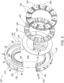
Fig. 2 is an exploded view of a thrust bearing assembly as may be described herein. -
Fig. 3 is a side sectional view of the thrust bearing assembly ofFig. 2 . -
Fig. 4 is a perspective view of a thrust pad assembly of the thrust bearing assembly ofFig. 2 without a polymer liner on a front face thereof. -
Fig. 5 is a perspective view of a thrust pad assembly of the thrust bearing assembly ofFig. 2 with a polymer liner on a front face thereof. -
Fig. 6 is a side sectional view of the thrust pad assembly ofFig. 4 . -
Fig. 7 is a perspective view of a thrust pad assembly of the thrust bearing assembly ofFig. 2 with a load cell on a rear face thereof. -
Fig. 8 is a perspective view of a thrust pad assembly of the thrust bearing assembly ofFig. 2 with a plug on a rear face thereof. - Referring now to the drawings, in which like numerals refer to like elements throughout the several views,
Fig. 1 shows a schematic diagram of an example of a turbomachine 5, in this case a steam turbine 10. Generally described, the steam turbine 10 may include ahigh pressure section 15 and anintermediate pressure section 20. Other pressures in other sections also may be used herein. An outer shell orcasing 25 may be divided axially into anupper half section 30 and alower half section 35. Acentral section 40 of thecasing 25 may include a highpressure steam inlet 45 and an intermediatepressure steam inlet 50. Within thecasing 25, thehigh pressure section 15 and theintermediate pressure section 20 may be arranged about arotor shaft 55. Therotor shaft 55 may be supported by a number ofthrust bearings 60 andjournal bearings 65. Anannular section divider 70 may extend radially inward from thecentral section 40 towards therotor shaft 55. Thedivider 70 may include a number ofpacking casings 75. Other components and other configurations may be used. - During operation, the high
pressure steam inlet 45 receives high pressure and high temperature steam from a steam source. The steam may be routed through thehigh pressure section 15 such that work is extracted from the steam by rotation of therotor shaft 55. The steam exits thehigh pressure section 15 and then may be returned to the steam source for reheating. The reheated steam then may be rerouted to the intermediatepressure steam inlet 50. The steam may be returned to theintermediate pressure section 20 at a reduced pressure as compared to the steam entering thehigh pressure section 15 but at a temperature that is approximately equal to the temperature of the steam entering thehigh pressure section 15. Other components and other configurations may be used herein. -
Figs. 2 and3 show a thrust bearingassembly 100 as may be described herein. The thrust bearingassembly 100 may include athrust casing machining 110. Thethrust casing machining 110 may include afirst half 120 and asecond half 130. Thefirst half 120 and thesecond half 130 may be joined via a number ofanti-rotation pins 140 and the like. Other types of joinder devices may be used herein. Thethrust casing machining 110 may define aninner aperture 150 for therotor shaft 55 to extend therethrough. Thethrust casing machining 110 may have aninner wall 160 defining theinner aperture 150, anouter wall 170, and arecess 180 therebetween. Therecess 180 may be sized to accept the remaining components of thethrust casing machining 110 therein as will be described in more detail below. Theouter wall 170 radially encloses thethrust casing machining 110. Theouter wall 170 includes a number ofoil plenums 190 formed therein with each of theoil plenums 190 having anoil aperture 200 extending therethrough. Theoil plenums 190 may be formed in the shape of elongated slots with theoil aperture 200 at one end. Other components and other configurations may be used herein. - The thrust bearing
assembly 100 includes ashim 210 sized for and positioned within therecess 180 of thethrust casing machining 110. Adjacent to theshim 210 may be a number of levelinglinks 220. Specifically, a number oflower leveling links 230 positioned on theshim 210 and a number of interfacingupper leveling lings 240 positioned, as will be described below, adjacent to a number ofthrust pad assemblies 250. The levelinglinks 220 may be of conventional design. Therespective leveling links 220 may push up and down to ensure proper alignment and load equalization of thethrust pad assemblies 250. Thethrust bearing assembly 100 includes thethrust pad assemblies 250 assembled in a thrustpad assembly loop 260. Any number of thethrust pad assemblies 250 may be used herein. Other components and other configurations may be used herein. -
Figs. 4-8 show examples of thethrust pad assemblies 250. As is shown inFig. 4 , eachthrust pad assembly 250 includes athrust pad machining 270. Eachthrust pad machining 270 is a shaped as asegment 280 of the thrustpad assembly loop 260 with a curvedouter diameter 290, a curvedinner diameter 300, a trailingedge 310, aleading edge 320, a flatfront face 330, and a flatrear face 340. Thefront face 330 is surrounded by aninsert flange 350 extending along theouter diameter 290, theleading edge 320, and theinner diameter 300. As is shown inFig. 5 , theinsert flange 350 allows apolymer liner 360 to be slid in and out via the trailingedge 310 and to be mechanically retained therein. Thepolymer liner 360 may be at least partly of made of polyetheretherketone (PEEK), polytetrafluroethylene (PTFE), and other types of polymers and blends thereof. Other types of materials may be used herein. Thepolymer liner 360 may be removed and replaced. Other components and other configurations may be used herein. - As is shown in
Figs. 4-6 , eachthrust pad assembly 250 includes anoil feed configuration 370. Theoil feed configuration 370 may include anoil input port 380 on theouter diameter 290, anoil feed channel 390 extending within thethrust pad machining 270, and a number ofoil output ports 400 on thefront face 330. In this example, a firstoil output port 410 and a secondoil output port 420 are shown although any number of theoil output ports 400 may be used herein. Theoil feed configuration 370 also includes anoil feed groove 430 formed in thepolymer liner 360. Theoil feed groove 430 may be sized and shaped to surround at least in part theoil output ports 400. Theoil input port 380 may align with theoil plenum 190 of thethrust casing machining 110 such that a flow ofoil 440 may extend therethrough. Other components and other configurations may be used herein. - As is shown in
Figs. 7 and 8 , some of thethrust pad assemblies 250 in the thrustpad assembly loop 260 may include aload cell 450 positioned along therear face 340. Theload cell 450 may be a TC series (tension/compression) load cell such as a strain gauge transducer used to measure loads in static and dynamic applications, in tension and compression, with high accuracy. Other types ofload cells 450 may be used herein. Any number of temperature sensors also may be used. As is shown inFig. 7 , theload cell 450 may be positioned within therear face 340 and locked into place via acompression fitting 460 and the like. Theouter diameter 290 may have awiring channel 470 formed therein to accommodate the wiring of theload cell 450.Fig. 8 shows athrust pad assembly 250 without theload cell 450. Instead, aplug 480 may be positioned therein. Other components and other configurations may be used herein. - In use, the flow of
oil 440 may flow from theoil plenums 190 of thethrust casing machining 110 and into theoil feed configurations 370 of thethrust pad assemblies 250. The flow ofoil 440 may flow into theoil input port 380, through theoil feed channel 390, out via theoil output ports 400 and theoil feed groove 430, and onto thepolymer liner 360 for lubrication. - The use of the separate
thicker polymer liner 360 that is mechanically retained (not bonded) within theinsert flange 350 allows thethrust pad assembly 250 to use theoil feed groove 430 without the concern of bond integrity. Thethrust pad assembly 250 combines this with theoil feed configuration 370 to connect theoil feed groove 430 with theoil plenums 190 of thethrust casing machining 110. As a result, the overallthrust bearing assembly 100 may have a lower part count with reduced power losses. Specifically, thethrust bearing assembly 100 reduces power losses as compared to a flooded design and reduces cost and complexity as compared to a spray bar oil feed design. The use of theoil feed groove 430 on thefront face 330 also reduces the space required between thethrust pad assemblies 250, thus increasing the load carrying area for the same size thrustcasing machining 110. - It should be apparent that the foregoing relates only to certain embodiments of this application and resultant patent. Numerous changes and modifications may be made herein by one of ordinary skill in the art without departing from the general spirit and scope of the invention as defined by the following claims and the equivalents thereof.
- Further aspects of the invention are provided by the subject matter of the following clauses:
- 1. A thrust pad assembly for a turbomachine, comprising: a thrust pad machining; the thrust pad machining comprising an insert flange; a polymer liner positioned within the insert flange; and an oil feed configuration; the oil feed configuration comprising one or more oil output ports extending through the thrust pad machining and an oil feed groove in the polymer liner.
- 2. The thrust pad assembly of clause 1, wherein the thrust pad machining comprises a front face and a rear face.
- 3. The thrust pad assembly of any preceding clause, wherein the polymer liner is positioned on the front face.
- 4. The thrust pad assembly of any preceding clause, wherein the thrust pad machining further comprises an outer diameter, an inner diameter, a trailing edge, and a leading edge.
- 5. The thrust pad assembly of any preceding clause, wherein the insert flange extends along the outer diameter, the leading edge, and the inner diameter of the front face.
- 6. The thrust pad assembly of any preceding clause, wherein the polymer liner is inserted into the insert flange along the trailing edge of the front face.
- 7. The thrust pad assembly of any preceding clause, wherein the oil feed configuration comprises an oil input port in the outer diameter.
- 8. The thrust pad assembly of any preceding clause, wherein the oil feed configuration comprises an oil feed channel in communication with the oil input port and the one or more oil output ports.
- 9. The thrust pad assembly of any preceding clause, wherein the one or more oil output ports comprise a first oil output port and a second oil output port.
- 10. The thrust pad assembly of any preceding clause, wherein the thrust pad machining comprises a load cell on the rear face.
- 11. The thrust pad assembly of any preceding clause, wherein the load cell is held on place by a compression fitting.
- 12. The thrust pad assembly of any preceding clause, wherein the outer diameter comprises a wiring channel in communication with the load cell.
- 13. The thrust pad assembly of any preceding clause, wherein the thrust pad machining comprises a plug on the rear face.
- 14. The thrust pad assembly of any preceding clause, further comprising a flow of oil extending through the oil configuration to the polymer liner.
- 15. A method of lubricating a thrust pad assembly of a thrust bearing assembly with a flow of oil, comprising: flowing the flow of oil through an oil plenum in a thrust casing machining; flowing the flow of oil from the oil plenum to an oil feed configuration of the thrust bearing assembly; and flowing the flow of oil through the oil feed configuration and through an oil feed groove in a polymer liner of the thrust pad assembly.
- 16. A thrust bearing assembly for a turbomachine, comprising: a thrust casing machining; the thrust casing machining comprises a plurality of oil plenums; and a plurality of thrust pad assemblies positioned in the thrust casing machining; wherein each of the plurality of thrust pad assemblies comprises an insert flange with a polymer liner therein and an oil feed configuration; and wherein the oil feed configuration comprising one or more oil output ports extending through an oil feed groove in the polymer lining.
- 17. The thrust bearing assembly of any preceding clause, wherein each of the plurality of thrust pad assemblies comprise a front face and a rear face.
- 18. The thrust bearing assembly of any preceding clause, wherein the polymer liner is positioned on the front face.
- 19. The thrust bearing assembly of any preceding clause, wherein the oil feed configuration of each of the plurality of thrust pad assemblies comprises an oil input port in communication with one of the plurality of oil plenums of the thrust casing machining.
- 20. The thrust pad bearing of any preceding clause, wherein the rear face of one or more of the plurality of thrust bearing assemblies comprises a load cell.
- All embodiments in the clauses can be combined with each other in any order or combination.
Claims (15)
- A thrust pad assembly (250) for a turbomachine (5), comprising:a thrust pad machining (270);the thrust pad machining (270) comprising an insert flange (350);a polymer liner (360) positioned within the insert flange (350); andan oil feed configuration (370);the oil feed configuration (370) comprising one or more oil output ports (400) extending through the thrust pad machining (270) and an oil feed groove (430) in the polymer liner (360).
- The thrust pad assembly (250) of claim 1, wherein the thrust pad machining (270) comprises a front face (330) and a flat face (340).
- The thrust pad assembly (250) of claim 2, wherein the polymer liner (360) is positioned on the front face (330).
- The thrust pad assembly (250) of claim 2, wherein the thrust pad machining (270) further comprises an outer diameter (290), an inner diameter (300), a trailing edge (310), and a leading edge (320).
- The thrust pad assembly (250) of claim 4, wherein the insert flange extends (350) along the outer diameter (290), the leading edge (320), and the inner diameter (300) of the front face (330).
- The thrust pad assembly (250) of claim 5, wherein the polymer liner (360) is inserted into the insert flange (350) along the trailing edge (310) of the front face (330).
- The thrust pad assembly (250) of claim 4, wherein the oil feed configuration (370) comprises an oil input port (380) in the outer diameter (290).
- The thrust pad assembly (250) of claim 7, wherein the oil feed configuration (370) comprises an oil feed channel (390) in communication with the oil input port (380) and the one or more oil output ports (400).
- The thrust pad assembly (250) of claim 1, wherein the one or more oil output ports (400) comprise a first oil output port (410) and a second oil output port (420).
- The thrust pad assembly (250) of claim 2, wherein the thrust pad machining (270) comprises a load cell (450) on the flat face (340).
- The thrust pad assembly (250) of claim 10, wherein the load cell (450) is held on place by a compression fitting (460).
- The thrust pad assembly (250) of claim 10, wherein the outer diameter (290) comprises a wiring channel (470) in communication with the load cell (450).
- The thrust pad assembly (250) of claim 2, wherein the thrust pad machining (370) comprises a plug (480) on the flat face (340).
- The thrust pad assembly (250) of claim 1, further comprising a flow of oil (440) extending through the oil feed configuration (370) to the polymer liner (360).
- A method of lubricating a thrust pad assembly (100) of a thrust bearing assembly (250) with a flow of oil (440), comprising:flowing the flow of oil (440) through an oil plenum (190) in a thrust casing machining (110);flowing the flow of oil (440) from the oil plenum (190) to an oil feed configuration (370) of the thrust pad assembly (250); andflowing the flow of oil (440) through the oil feed configuration (370) and through an oil feed groove (430) in a polymer liner (360) of the thrust pad assembly (250).
Applications Claiming Priority (1)
| Application Number | Priority Date | Filing Date | Title |
|---|---|---|---|
| US18/167,971 US11746676B1 (en) | 2023-02-13 | 2023-02-13 | Thrust bearing assembly |
Publications (1)
| Publication Number | Publication Date |
|---|---|
| EP4414577A1 true EP4414577A1 (en) | 2024-08-14 |
Family
ID=87882462
Family Applications (2)
| Application Number | Title | Priority Date | Filing Date |
|---|---|---|---|
| EP24153006.2A Withdrawn EP4414576A1 (en) | 2023-02-13 | 2024-01-19 | Thrust bearing assembly |
| EP24157200.7A Pending EP4414577A1 (en) | 2023-02-13 | 2024-02-12 | Thrust bearing assembly |
Family Applications Before (1)
| Application Number | Title | Priority Date | Filing Date |
|---|---|---|---|
| EP24153006.2A Withdrawn EP4414576A1 (en) | 2023-02-13 | 2024-01-19 | Thrust bearing assembly |
Country Status (5)
| Country | Link |
|---|---|
| US (1) | US11746676B1 (en) |
| EP (2) | EP4414576A1 (en) |
| JP (1) | JP2024114625A (en) |
| KR (1) | KR20240126422A (en) |
| CN (1) | CN118482093A (en) |
Families Citing this family (1)
| Publication number | Priority date | Publication date | Assignee | Title |
|---|---|---|---|---|
| CN120739800A (en) * | 2025-07-23 | 2025-10-03 | 东方电气集团东方电机有限公司 | Auxiliary starting thrust bearing bush, thrust bearing and use method |
Citations (3)
| Publication number | Priority date | Publication date | Assignee | Title |
|---|---|---|---|---|
| US20140377063A1 (en) * | 2013-06-20 | 2014-12-25 | Siemens Aktiengesellschaft | Wind power plant having a sliding bearing |
| CN108571516A (en) * | 2017-11-15 | 2018-09-25 | 湖南崇德工业科技有限公司 | A kind of polymer thrust bearing |
| EP3276191B1 (en) * | 2016-07-28 | 2020-11-11 | GE Renewable Technologies | Hydrodynamic bearing pad construction |
Family Cites Families (15)
| Publication number | Priority date | Publication date | Assignee | Title |
|---|---|---|---|---|
| JP2000169697A (en) | 1998-12-08 | 2000-06-20 | Daido Metal Co Ltd | Double-layer bearing |
| US6746152B2 (en) | 2001-07-27 | 2004-06-08 | Pioneer Motor Bearing Company | Thrust bearing and method for equalizing load |
| JP2006342926A (en) * | 2005-06-10 | 2006-12-21 | Pooraito Kk | Thrust bearing unit for motor |
| CN102119280B (en) | 2009-02-25 | 2013-09-04 | 三菱重工业株式会社 | Oil supply nozzle for thrust bearing |
| CA2767461C (en) * | 2009-07-10 | 2017-06-06 | Siemens Aktiengesellschaft | Wind turbine main bearing |
| US20110123327A1 (en) | 2009-11-20 | 2011-05-26 | General Electric Company | Bearing assembly using different type thrust bearings |
| JP5119281B2 (en) | 2010-02-17 | 2013-01-16 | 株式会社日立製作所 | Combined bearing device |
| US9482274B2 (en) | 2014-11-25 | 2016-11-01 | General Electric Company | Compliant hybrid gas lubricated thrust bearing |
| CN106640976B (en) * | 2016-12-20 | 2019-02-26 | 湖南崇德工业科技有限公司 | A kind of thrust bearing |
| US10871072B2 (en) | 2017-05-01 | 2020-12-22 | General Electric Company | Systems and methods for dynamic balancing of steam turbine rotor thrust |
| CN207583836U (en) * | 2017-11-15 | 2018-07-06 | 湖南崇德工业科技有限公司 | A kind of polymer thrust bearing |
| AU2017441427B2 (en) | 2017-12-01 | 2024-09-05 | Ge Renewable Technologies | Bearing pad for a hydro-generating unit and hydro-generating unit with such a bearing pad |
| US10801549B2 (en) | 2018-05-31 | 2020-10-13 | General Electric Company | Axial load management system |
| CN113775642B (en) * | 2021-09-15 | 2023-08-22 | 上海涟屹轴承科技有限公司 | Thrust bearing and rotating shaft |
| CN113790206A (en) * | 2021-09-15 | 2021-12-14 | 上海涟屹轴承科技有限公司 | Composite material transmission shaft and sliding bearing thereof |
-
2023
- 2023-02-13 US US18/167,971 patent/US11746676B1/en active Active
-
2024
- 2024-01-19 EP EP24153006.2A patent/EP4414576A1/en not_active Withdrawn
- 2024-01-22 JP JP2024007151A patent/JP2024114625A/en active Pending
- 2024-02-08 CN CN202410176729.8A patent/CN118482093A/en active Pending
- 2024-02-08 KR KR1020240019408A patent/KR20240126422A/en active Pending
- 2024-02-12 EP EP24157200.7A patent/EP4414577A1/en active Pending
Patent Citations (3)
| Publication number | Priority date | Publication date | Assignee | Title |
|---|---|---|---|---|
| US20140377063A1 (en) * | 2013-06-20 | 2014-12-25 | Siemens Aktiengesellschaft | Wind power plant having a sliding bearing |
| EP3276191B1 (en) * | 2016-07-28 | 2020-11-11 | GE Renewable Technologies | Hydrodynamic bearing pad construction |
| CN108571516A (en) * | 2017-11-15 | 2018-09-25 | 湖南崇德工业科技有限公司 | A kind of polymer thrust bearing |
Also Published As
| Publication number | Publication date |
|---|---|
| EP4414576A1 (en) | 2024-08-14 |
| JP2024114625A (en) | 2024-08-23 |
| CN118482093A (en) | 2024-08-13 |
| KR20240126422A (en) | 2024-08-20 |
| US11746676B1 (en) | 2023-09-05 |
Similar Documents
| Publication | Publication Date | Title |
|---|---|---|
| US5816776A (en) | Labyrinth disk with built-in stiffener for turbomachine rotor | |
| US11193385B2 (en) | Gas bearing seal | |
| US10132194B2 (en) | Seal segment low pressure cooling protection system | |
| US7980812B2 (en) | Low pressure turbine rotor disk | |
| US8876463B2 (en) | Interturbine vane with multiple air chambers | |
| US11008941B2 (en) | Sump housing for a gas turbine engine | |
| US9638244B2 (en) | Axial bearing arrangement | |
| US10036279B2 (en) | Thrust bearing | |
| US6578363B2 (en) | Air-cooled gas turbine exhaust casing | |
| US10001166B2 (en) | Gas distribution labyrinth for bearing pad | |
| EP2573329A2 (en) | Air system architecture for a mid-turbine frame module | |
| CN110878760B (en) | Seal components for turbomachinery | |
| CA2406479C (en) | Weep plug | |
| CN109415950A (en) | Fluid damping air bearing with integrally formed component | |
| US12000298B2 (en) | Device for pressurizing turbomachine downstream enclosure, and corresponding turbomachine | |
| ITCO20110029A1 (en) | CENTRIFUGAL AND TURBOMACHINE IMPELLER | |
| EP4414576A1 (en) | Thrust bearing assembly | |
| EP2930370A1 (en) | Centrifugal compressor, supercharger with same, and method for operating centrifugal compressor | |
| IT201600120314A1 (en) | TURBO-COMPRESSOR AND OPERATING METHOD OF A TURBO-COMPRESSOR | |
| CN120418545A (en) | Turbomachine, multistage rotor and method for manufacturing same | |
| US11492926B2 (en) | Bearing housing with slip joint | |
| US11549396B2 (en) | Mid-turbine frame for gas turbine engine | |
| EP2993313A1 (en) | Offtakes for gas turbine engine secondary gas flows | |
| US20200191016A1 (en) | Bearing support including hermetic squeeze film damper and accumulator volume | |
| EP3835606B1 (en) | Curved beam centering spring for a thrust bearing |
Legal Events
| Date | Code | Title | Description |
|---|---|---|---|
| PUAI | Public reference made under article 153(3) epc to a published international application that has entered the european phase |
Free format text: ORIGINAL CODE: 0009012 |
|
| STAA | Information on the status of an ep patent application or granted ep patent |
Free format text: STATUS: THE APPLICATION HAS BEEN PUBLISHED |
|
| AK | Designated contracting states |
Kind code of ref document: A1 Designated state(s): AL AT BE BG CH CY CZ DE DK EE ES FI FR GB GR HR HU IE IS IT LI LT LU LV MC ME MK MT NL NO PL PT RO RS SE SI SK SM TR |
|
| STAA | Information on the status of an ep patent application or granted ep patent |
Free format text: STATUS: REQUEST FOR EXAMINATION WAS MADE |
|
| 17P | Request for examination filed |
Effective date: 20250210 |
|
| RAP3 | Party data changed (applicant data changed or rights of an application transferred) |
Owner name: GE VERNOVA TECHNOLOGY GMBH |
|
| STAA | Information on the status of an ep patent application or granted ep patent |
Free format text: STATUS: EXAMINATION IS IN PROGRESS |
|
| 17Q | First examination report despatched |
Effective date: 20260423 |