EP4414561A1 - Ceiling assembly and fan lamp - Google Patents
Ceiling assembly and fan lamp Download PDFInfo
- Publication number
- EP4414561A1 EP4414561A1 EP22885805.6A EP22885805A EP4414561A1 EP 4414561 A1 EP4414561 A1 EP 4414561A1 EP 22885805 A EP22885805 A EP 22885805A EP 4414561 A1 EP4414561 A1 EP 4414561A1
- Authority
- EP
- European Patent Office
- Prior art keywords
- ceiling
- installation
- assembly
- connecting part
- bracket body
- Prior art date
- Legal status (The legal status is an assumption and is not a legal conclusion. Google has not performed a legal analysis and makes no representation as to the accuracy of the status listed.)
- Pending
Links
Images



Classifications
-
- F—MECHANICAL ENGINEERING; LIGHTING; HEATING; WEAPONS; BLASTING
- F04—POSITIVE - DISPLACEMENT MACHINES FOR LIQUIDS; PUMPS FOR LIQUIDS OR ELASTIC FLUIDS
- F04D—NON-POSITIVE-DISPLACEMENT PUMPS
- F04D25/00—Pumping installations or systems
- F04D25/02—Units comprising pumps and their driving means
- F04D25/08—Units comprising pumps and their driving means the working fluid being air, e.g. for ventilation
- F04D25/088—Ceiling fans
-
- F—MECHANICAL ENGINEERING; LIGHTING; HEATING; WEAPONS; BLASTING
- F04—POSITIVE - DISPLACEMENT MACHINES FOR LIQUIDS; PUMPS FOR LIQUIDS OR ELASTIC FLUIDS
- F04D—NON-POSITIVE-DISPLACEMENT PUMPS
- F04D29/00—Details, component parts, or accessories
- F04D29/60—Mounting; Assembling; Disassembling
- F04D29/601—Mounting; Assembling; Disassembling specially adapted for elastic fluid pumps
-
- F—MECHANICAL ENGINEERING; LIGHTING; HEATING; WEAPONS; BLASTING
- F21—LIGHTING
- F21S—NON-PORTABLE LIGHTING DEVICES; SYSTEMS THEREOF; VEHICLE LIGHTING DEVICES SPECIALLY ADAPTED FOR VEHICLE EXTERIORS
- F21S8/00—Lighting devices intended for fixed installation
- F21S8/04—Lighting devices intended for fixed installation intended only for mounting on a ceiling or the like overhead structures
- F21S8/043—Lighting devices intended for fixed installation intended only for mounting on a ceiling or the like overhead structures mounted by means of a rigid support, e.g. bracket or arm
-
- F—MECHANICAL ENGINEERING; LIGHTING; HEATING; WEAPONS; BLASTING
- F21—LIGHTING
- F21V—FUNCTIONAL FEATURES OR DETAILS OF LIGHTING DEVICES OR SYSTEMS THEREOF; STRUCTURAL COMBINATIONS OF LIGHTING DEVICES WITH OTHER ARTICLES, NOT OTHERWISE PROVIDED FOR
- F21V21/00—Supporting, suspending, or attaching arrangements for lighting devices; Hand grips
- F21V21/02—Wall, ceiling, or floor bases; Fixing pendants or arms to the bases
- F21V21/03—Ceiling bases, e.g. ceiling roses
-
- F—MECHANICAL ENGINEERING; LIGHTING; HEATING; WEAPONS; BLASTING
- F21—LIGHTING
- F21V—FUNCTIONAL FEATURES OR DETAILS OF LIGHTING DEVICES OR SYSTEMS THEREOF; STRUCTURAL COMBINATIONS OF LIGHTING DEVICES WITH OTHER ARTICLES, NOT OTHERWISE PROVIDED FOR
- F21V21/00—Supporting, suspending, or attaching arrangements for lighting devices; Hand grips
- F21V21/34—Supporting elements displaceable along a guiding element
-
- F—MECHANICAL ENGINEERING; LIGHTING; HEATING; WEAPONS; BLASTING
- F05—INDEXING SCHEMES RELATING TO ENGINES OR PUMPS IN VARIOUS SUBCLASSES OF CLASSES F01-F04
- F05D—INDEXING SCHEME FOR ASPECTS RELATING TO NON-POSITIVE-DISPLACEMENT MACHINES OR ENGINES, GAS-TURBINES OR JET-PROPULSION PLANTS
- F05D2260/00—Function
- F05D2260/30—Retaining components in desired mutual position
- F05D2260/33—Retaining components in desired mutual position with a bayonet coupling
-
- F—MECHANICAL ENGINEERING; LIGHTING; HEATING; WEAPONS; BLASTING
- F21—LIGHTING
- F21V—FUNCTIONAL FEATURES OR DETAILS OF LIGHTING DEVICES OR SYSTEMS THEREOF; STRUCTURAL COMBINATIONS OF LIGHTING DEVICES WITH OTHER ARTICLES, NOT OTHERWISE PROVIDED FOR
- F21V33/00—Structural combinations of lighting devices with other articles, not otherwise provided for
- F21V33/0088—Ventilating systems
- F21V33/0096—Fans, e.g. ceiling fans
Definitions
- the present application relates to the technical field of lighting device, and in particular to a ceiling assembly and a fan lamp.
- Fan lamp is a commonly used household appliance, and is a combination of a lighting lamp and a fan, the fan lamp not only has a lighting performance of the lighting lamp, but also has a thermal dissipation performance of the fan, and has become a most common lamp for indoor lighting, and widely applied in various scenarios such as in a house, an office, a public place of entertainment, or the like.
- ceiling box of the fan lamp is fixed with screws, and need multiple people to cooperate, in which one person lift the fan lamp and make the installation hole of ceiling box be aligned with a screw hole of a bracket body, and another person fastens the fan lamp through the screw, the installation process is difficult, and an appearance of the fan lamp is not aesthetically pleasing, which affects the overall aesthetics of the fan lamp.
- the installation process of the fan lamp often need climbing work, using screws for fixing make the installation and disassembly of the fan lamp difficult, and a labor intensity of an installer is high, which is easy to endanger a personal safety of the installer, and is time-consuming and laborious.
- the purpose of present application is to provide a ceiling assembly for fan lamp installation, the ceiling assembly has a simple structure, aesthetically pleasing appearance, and provides easy and quick installation.
- the present application provides a ceiling assembly, configured for an installation of a fan lamp, and comprising: a bracket body and a ceiling box, wherein the ceiling box has an installation cavity, and the bracket body is housed in the installation cavity, the ceiling box is provided with a first connecting part, the bracket body is provided with a second connecting part at a position corresponding to the first connecting part, the first connecting part is detachably connected with the second connecting part, and the first connecting part is provided with a first guiding part on a connecting surface thereof corresponding to the second connecting part.
- the first guiding part is inclined, and a cross-sectional area, along a height direction, at either one position of the first guiding part is positively related to a spacing distance between the either one position of the first guiding part and a guiding end of the first connecting part.
- a reinforcing rib is provided on a side of the first connecting part away from the connecting surface.
- two first connecting parts are provided, and the two first connecting parts are provided in a mirroring-configuration.
- the bracket body further comprises an installation part, the installation part is connected to an installation base, and there is a first height difference between the installation part and the second connecting part along a height direction.
- the second connecting part comprises a second guiding part and a limiting part, the limiting part and the second guiding part are respectively located at two ends of the second connecting part, and an extension direction of the limiting part is opposite to an extension direction of the second guiding part.
- the limiting part is fixedly connected with the installation part and the second connecting part.
- the ceiling box is provided with a first installation hole
- the bracket body is provided with a second installation hole
- a suspension assembly passes through the first installation hole and the second installation hole and is at least partially housed within the ceiling assembly.
- the bracket body further comprises a base plate, the base plate is provided with a notch, the notch is connected to the second installation hole, and the suspension assembly is detachably connected to the bracket body through the notch.
- Another purpose of the present application is to provide a fan lamp having the aforementioned ceiling assembly, the fan lamp can be installed and disassembled by a single person, which saves time and labor, and is efficient and safe.
- the present application provides a fan lamp, comprising: a suspension assembly, a blade assembly, a light source assembly, and the abovementioned ceiling assembly, the ceiling assembly is detachably connected to the suspension assembly, the suspension assembly is fixedly connected to the blade assembly and the light source assembly, and the light source assembly is disposed on a side of the blade assembly away from the ceiling assembly.
- the beneficial effect of the present application is that, compared with the prior art, the ceiling assembly of the present application has a simple structure, aesthetically pleasing appearance, and is detachably connected by means of a rotary connection, through which the installation process is simplified, the installation cost is reduced, and the installation is convenient and fast, so that the fan lamp having the ceiling assembly can be installed and disassembled by a single person, thereby saving time and labor, and being efficient and safe.
- a space of the ceiling box is well utilized by disposing the connecting part of the ceiling assembly in the installation cavity of the ceiling box, which improves the aesthetics of the appearance of the fan lamp.
- the ceiling assembly 1 includes a bracket body 12 and a ceiling box 11, the bracket body 12 and the ceiling box 11 are detachably connected, and the ceiling box 11 is installed on an installation base through the bracket body 12.
- the installation base is used for hanging the fan lamp 100, for example, the installation base may be a ceiling of a house or the like.
- the installation process is simplified, the installation cost is reduced, and processes for installing and disassembling the fan lamp 100 having the ceiling assembly 1 is convenient and quick, and the installation and disassembly can be realized by a single person, which is time-saving and labor-saving, and highly efficient and safe.
- the ceiling box 11 has an installation cavity 111, and the bracket body 12 is housed in the installation cavity 111, so as to reduce a space occupied by the bracket body 12 and to improve the structural compactness of the fan lamp 100.
- the installation cavity 111 of the ceiling box 11 may also accommodate some functional components of the fan lamp 100, such as a drive assembly, a power supply assembly, a safety rope assembly 5, a terminal assembly 6, and the like, so as to better utilize the space of the ceiling box 11 and to improve a structural compactness and aesthetic appearance of the fan lamp 100.
- the ceiling box 11 includes a first annular part 112 and a truncated conical part 113 disposed below the first annular part 112, and the first annular part 112 and the truncated conical part 113 enclose to form the installation cavity 111.
- the truncated conical part 113 includes a first end and a second end, the first end and the second end are parallel to each other, and a cross-sectional area of the first end in a horizontal direction is larger than a cross-sectional area of the second end in the horizontal direction.
- a plane at which a top of the first annular part 112 is located is higher than or coplanar with a plane at which the installation part 121 of the bracket body 12 is located, so that the bracket body 12 is completely accommodated inside the ceiling box 11, and the structural compactness and aesthetics of appearance of the fan lamp 100 are improved.
- a bottom of the first annular part 112 is connected to the first end, so as to increase a volume of the installation cavity 111 of the ceiling box 11.
- a side of the second end toward the first end extends toward a position close to the first end to form a second annular part 114 and a third annular part 115 that have a same center of circle, a diameter of the second annular part 114 is smaller than a diameter of the third annular part 115, and a height of the second annular part 114 in a vertical direction is lower than a height of the third annular part 115 in the vertical direction.
- the bracket body 12 is housed within the installation cavity 111, and a base plate 123 of the bracket body 12 is located over the second annular part 114, and a sidewall 122 of the bracket body 12 abuts an inner wall of the third annular part 115, so as to limit and fix the bracket body 12 in the installation cavity 111 of the ceiling box 11, thereby limiting a degree of freedom of the bracket body 12 in the horizontal direction, and improving the connection stability of the ceiling assembly 1.
- a first connecting part 116 is provided on an inner wall of the first annular part 112 of the ceiling box 11, a second connecting part 124 is provided on the bracket body 12 at a position corresponding to the first connecting part 116, the first connecting part 116 and the second connecting part 124 are detachably connected, and a first guiding part 1161 and a joint part 1162 are provided on a connecting surface of the first connecting part 116 corresponding to the second connecting part 124.
- the first guiding part 1161 is disposed to be inclined, preferably, the first guiding part 1161 is an inclined bevel, and an end of the first guiding part 1161 away from the joint part 1162 is a guiding end 1163, and a cross-sectional area, along the height direction, of the first guiding part 1161 at either one position is positively related to a spacing distance between the said either one position of the first guiding part 1161 and the guiding end 1163 of the first connecting part 116.
- the second connecting part 124 is made to slide quickly along the first guiding part 1161 and onto a connecting surface located below the first connecting part 116, so that the first connecting part 116 and the second connecting part 124 are guided to be smoothly joined, which facilitates the detachable connection of the first connecting part 116 and the second connecting part 124.
- the joint part 1162 is connected to an end of the first connecting part 116 away from the guiding end 1163, and a width of the joint part 1162 in the horizontal direction is larger than a width of the first guiding part 1161 in the horizontal direction, so as to increase a tightness of the joint between the first connecting part 116 and the second connecting part 124.
- the joint part 1162 is provided horizontally, of course, the joint part 1162 may also be provided with other structures that match the second connecting part 124, which is not limited in the present application.
- a gravity of the ceiling box 11 itself is utilized to compact the first connecting part 116 and the second connecting part 124, so as to improve a stability of the connection between the ceiling box 11 and the bracket body 12.
- a reinforcing rib 1164 is disposed on a side of the first connecting part 116 away from the connecting surface, and the reinforcing rib 1164 is provided to play a role in positioning installation and providing a stable support for the first connecting part 116, so that the first connecting part 116 and the second connecting part 124 realize a positioning connection of the ceiling assembly 1, while increasing a structural strength of the first connecting part 116, and improving a connection firmness of the ceiling assembly 1.
- the bracket body 12 includes an installation part 121, a sidewall 122, and a bottom wall, the installation part 121 is connected to the installation base, the sidewall 122 is connected to the installation part 121 and the bottom wall, and the bottom wall is connected to the second annular part 114 of the ceiling box 11.
- the bracket body 12 may be an integrally-formed stamped structure, so that the structural strength of the bracket body 12 is enhanced, and connection fracture of the bracket body 12 can be avoided.
- the installation part 121 is provided with one or more first fixing hole, and a fastener such as a bolt passes through the first fixing hole and is fixedly connected to the installation base, and an accommodation space 126 is formed between the sidewall 122, an installation wall and the bottom wall of the bracket body 12, the accommodation space 126 is used to accommodate components such as a suspension assembly 2, a driving assembly of the fan lamp 100, or the like, so as to increase the structural compactness and aesthetics of the fan lamp 100.
- the second connecting part 124 is provided below the installation part 121 of the bracket body 12, i.e., there exists a first height difference along the height direction between the installation part 121 and the second connecting part 124 to form a yielding space 125 on the bracket body 12, and facilitate a rotational snap connection of the first connecting part 116 on the ceiling box 11 and the second connecting part 124, meanwhile, the first connecting part 116 and the second connecting part 124 are both accommodated in the installation cavity 111 of the ceiling box 11 to fully utilize an internal space of the ceiling box 11 and improve the aesthetics of appearance of the fan lamp 100.
- the second connecting part 124 includes a second guiding part 1241 and a limiting part 1242, the limiting part 1242 and the second guiding part 1241 are located at two ends of the second connecting part 124, and an extension direction of the limiting part 1242 is opposite to an extension direction of the second guiding part 1241.
- the second guide part 1241 extends obliquely and downwardly to form a beveled guiding area, so as to guide the smooth joint between the first connecting part 116 and the second connecting part 124, and to reduce a fit accuracy requirement of the first connecting part 116 with the second connecting part 124.
- the limiting part 1242 extends upwardly and is fixedly connected with the installation part 121 and the second connecting part 124, so as to limit and stop the first connecting part 116, prevent the first connecting part 116 from sliding out of the second connecting part 124, thereby realizing the effect of anti-detachment, and improving the connection stability of the ceiling assembly 1.
- an amount of the first connecting parts 116 is multiple, a plurality of first connecting parts 116 are uniformly arranged at a same circumference of an inner wall of the ceiling box 11.
- An amount of the second connecting parts 124 is multiple, and is the same as the amount of the first connecting parts 116, and a plurality of second connecting parts 124 are uniformly arranged at a same circumference of the bracket body 12.
- two first connecting parts 116 are provided, and the two first connecting parts 116 are mirroring configured, and correspondingly, two second connecting parts 124 are also provided, and the two second connecting parts 124 are also mirroring configured.
- the two first connecting parts 116 and the two second connecting parts 124 realize a matching connection between the ceiling box 11 and the bracket body 12 through the guiding function of the first guiding part 1161 and the second guiding part 1241, so as to improve the stability of the connection of the ceiling assembly 1.
- the two first connecting parts 116 and the two second connecting parts 124 are both slid in a direction away from each other to realize the disassembly of the ceiling box 11 and the bracket body 12.
- the installation part 121 of the bracket body 12 is provided with a first protruding part 1211 and a second protruding part 1212, the first protruding part 1211 and the second protruding part 1212 are provided to face each other, and the first protruding part 1211 and the second protruding part 1212 may be connected by sliding connection.
- the strength of the bracket body 12 can be improved while a volume of the bracket body 12 can be adjusted, thereby facilitating the installation of the bracket body 12.
- the ceiling box 11 is provided with a first installation hole 117
- the bracket body 12 is provided with a second installation hole 1231
- the second installation hole 1231 is in spatial communication with the accommodation space 126
- the suspension assembly 2 passes through the first installation hole 117 and the second installation hole 1231 and is at least partially housed within the ceiling assembly 1 to realize the suspension installation of the fan lamp 100.
- the suspension assembly 2 includes a hanging rod 21 and a hanging ball 22, and the hanging rod 21 and the hanging ball 22 are detachably connected by threads, which is convenient for the installation and disassembly of the hanging rod 21 and the hanging ball 22, and convenient for the maintenance of the fan lamp 100. Further, in order to prevent the hanging rod 21 from detaching from the hanging ball 22, the hanging rod 21 and the hanging ball 22 may also be locked by fasteners such as screws in an optional embodiment to achieve fixation between the hanging rod 21 and the hanging ball 22.
- the hanging ball 22 passes through the first installation hole 117 and the second installation hole 1231, and is located in the accommodation space 126 and clamped in the second installation hole 1231, and the hanging rod 21 may be connected to a part of the hanging ball 22 that extends out of the accommodation space 126, and an end of the hanging rod 21 away from the hanging ball 22 may be connected to a blade assembly 3 and a light source assembly 4 to facilitate the suspension installation of the fan lamp 100.
- the base plate 123 is provided with a notch 1232, and the notch 1232 is connected with the second installation hole 1231, and the suspension assembly 2 is detachably connected with the bracket body 12 through the notch 1232.
- the hanging rod 21 is disassembled from the bracket body 12, the hanging rod 21 is lifted, and moved out of the bracket body 12 from the notch 1232.
- the hanging rod 21 is installed with the bracket body 12, the hanging rod 21 is lifted, and the hanging rod 21 is moved into the bracket body 12 from the notch 1232, then upon lowering the hanging rod 21, the hanging ball 22 is just secured in the second installation hole 1231.
- the detachable connection between the suspension assembly 2 and the bracket body 12 is realized, which is convenient for the assembly and disassembly of the fan lamp 100.
- a limit block 7 is further provided between the hanging ball 22 and the second installation hole 1231, and the limit block 7 is secured to the upper part of the second installation hole 1231 of the bracket body 12 by screw(s).
- a third installation hole 71 is provided in the limit block 7, and optionally, the limit block 7 is provided with an opening 72 at a position corresponding to the notch 1232 of the bracket body 12, and the opening 72 is connected to the third installation hole 71 to facilitate the detachably connection of the suspension assembly 2 and the bracket body 12.
- a cross-sectional dimension of the hanging rod 21 is smaller than that of the opening 72 of the limiting block 7 and that of the notch 1232 of the bracket body 12, and the cross-sectional dimension of the hanging ball 22 is larger than that of the opening 72 of the limiting block 7 and the notch 1232 of the bracket body 12.
- the hanging ball 22 closely abuts an upper end surface of the limiting block 7 and subjected to a limiting effect of the limiting block 7, so that the hanging rod 21 and the fan assembly hanging installed through the hanging rod 21 are hanging installed on the bracket body 12.
- the limiting block 7 in the embodiment of the present application has an inclined or a curved support surface, and accordingly, the outer side surface of the hanging ball 22 has an inclined or a curved surface.
- the outer side surface of the hanging ball 22 closely fits the support surface of the limiting block 7, thereby increasing a contact area between the hanging ball 22 and the limiting block 7, meanwhile, the acting force on the outer side surface of the hanging ball 22 applied by the support surface can be decomposed into an axial force and a radial force, the axial force can counteract an effect of gravity of the fan assembly, and the radial force can prevent the hanging ball 22 from moving and shifting with respect to the limiting block 7, so as to ensure the stability of the support for the hanging ball 22.
- the present application provides a preferred embodiment of the fan lamp 100, which includes the suspension assembly 2, the blade assembly 3, the light source assembly 4, and the above-described ceiling assembly 1.
- the ceiling assembly 1 is detachably connected to the suspension assembly 2, the suspension assembly 2 is fixedly connected to the blade assembly 3 and the light source assembly 4, and the light source assembly 4 is disposed on a side of the blade assembly 3 away from the ceiling assembly 1.
- the ceiling assembly 1 is used to realize the connection between the fan lamp 100 and the installation base, thereby realizing the installation of the fan lamp 100.
- the suspension assembly 2 can realize the connection between the blade assembly 3 and the ceiling assembly 1, i.e., a length of the hanging rod 21 in the suspension assembly 2 can be set flexibly, and optionally, the hanging rod 21 can adopt a multistage structure, such that the user can adjust the length of the hanging rod 21 according to his or her own needs so as to change the installation height of the fan lamp 100.
- the blade assembly 3 can realize a blowing function, and the light source assembly 4 can perform lighting, thereby making the fan lamp 100 more functional.
- the bracket body 12 in the ceiling assembly 1 can first be fixedly installed on the installation base by a fastener such as a screw, the terminal assembly 6 is electrically connected to mains power, and the hanging ball 22 in the suspension assembly 2 is snapped into the first installation hole 117 of the ceiling box 11, the hanging rod 21 of the suspension assembly 2 is sequentially connected to the blade assembly 3 and the light source assembly 4, a functional assembly is placed in the installation cavity 111 of the ceiling box 11, and after the ceiling box 11 is aligned with the bracket body 12, the hanging ball 22 of the suspension assembly 2 enters into the second installation hole 1231 of the bracket body 12 through the notch 1232 on the base plate 123, and is detachably connected to the bracket body 12.
- a fastener such as a screw
- the terminal assembly 6 is electrically connected to mains power
- the hanging ball 22 in the suspension assembly 2 is snapped into the first installation hole 117 of the ceiling box 11
- the hanging rod 21 of the suspension assembly 2 is sequentially connected to the blade assembly 3 and the light source assembly 4
- the ceiling box 11 is rotated counterclockwise, the first connecting part 116 of the ceiling box 11 and the second connecting part 124 of the bracket body 12 are rotationally snapped together under the guiding effect of the first guiding part 1161 and the second guiding part 1241, and the installation is completed after the first connecting part 116 of the ceiling box 11 contacts the limiting part 1242 on the bracket body 12.
- the ceiling box 11 is first lifted, and then rotated clockwise so that the first connecting part 116 of the ceiling box 11 is separated from the second connecting part 124 of the bracket body 12, and then the suspension assembly 2 is pulled out of the second installation hole 1231 from the notch 1232 of the base plate 123.
- the fan lamp 100 can be installed and disassembled by a single person, which is time-saving and labor-saving, and is efficient and safe.
- the ceiling assembly 1 of the present application has a simple structure, an aesthetically pleasing appearance, and is detachably connected by means of a rotary connection, the installation process is simplified, the installation cost is reduced, and the installation is convenient and fast, so that the fan lamp 100 having the ceiling assembly 1 can be installed and disassembled by a single person, which saves time and labor, and is efficient and safe.
- the present application makes good use of the space of the ceiling box 11 and improves the aesthetics of appearance of the fan lamp 100 by disposing the connecting part of the ceiling assembly 1 in the installation cavity 111 of the ceiling box 11.
Landscapes
- Engineering & Computer Science (AREA)
- General Engineering & Computer Science (AREA)
- Mechanical Engineering (AREA)
- Structures Of Non-Positive Displacement Pumps (AREA)
Abstract
Description
- This application claims the priority of
Chinese patent application No.202111240826.1, filed on October 25, 2021 Chinese patent application No.202122567464.9, filed on October 25, 2021 - The present application relates to the technical field of lighting device, and in particular to a ceiling assembly and a fan lamp.
- Fan lamp is a commonly used household appliance, and is a combination of a lighting lamp and a fan, the fan lamp not only has a lighting performance of the lighting lamp, but also has a thermal dissipation performance of the fan, and has become a most common lamp for indoor lighting, and widely applied in various scenarios such as in a house, an office, a public place of entertainment, or the like.
- In existing fan lamp, ceiling box of the fan lamp is fixed with screws, and need multiple people to cooperate, in which one person lift the fan lamp and make the installation hole of ceiling box be aligned with a screw hole of a bracket body, and another person fastens the fan lamp through the screw, the installation process is difficult, and an appearance of the fan lamp is not aesthetically pleasing, which affects the overall aesthetics of the fan lamp. In addition, the installation process of the fan lamp often need climbing work, using screws for fixing make the installation and disassembly of the fan lamp difficult, and a labor intensity of an installer is high, which is easy to endanger a personal safety of the installer, and is time-consuming and laborious.
- In view of above, it is necessary to provide a ceiling assembly and a fan lamp to solve the above problems.
- The purpose of present application is to provide a ceiling assembly for fan lamp installation, the ceiling assembly has a simple structure, aesthetically pleasing appearance, and provides easy and quick installation.
- In order to achieve the above purpose, the present application provides a ceiling assembly, configured for an installation of a fan lamp, and comprising: a bracket body and a ceiling box, wherein the ceiling box has an installation cavity, and the bracket body is housed in the installation cavity, the ceiling box is provided with a first connecting part, the bracket body is provided with a second connecting part at a position corresponding to the first connecting part, the first connecting part is detachably connected with the second connecting part, and the first connecting part is provided with a first guiding part on a connecting surface thereof corresponding to the second connecting part.
- As a further improvement of the present application, the first guiding part is inclined, and a cross-sectional area, along a height direction, at either one position of the first guiding part is positively related to a spacing distance between the either one position of the first guiding part and a guiding end of the first connecting part.
- As a further improvement of the present application, a reinforcing rib is provided on a side of the first connecting part away from the connecting surface.
- As a further improvement of the present application, two first connecting parts are provided, and the two first connecting parts are provided in a mirroring-configuration.
- As a further improvement of the present application, the bracket body further comprises an installation part, the installation part is connected to an installation base, and there is a first height difference between the installation part and the second connecting part along a height direction.
- As a further improvement of the present application, the second connecting part comprises a second guiding part and a limiting part, the limiting part and the second guiding part are respectively located at two ends of the second connecting part, and an extension direction of the limiting part is opposite to an extension direction of the second guiding part.
- As a further improvement of the present application, the limiting part is fixedly connected with the installation part and the second connecting part.
- As a further improvement of the present application, the ceiling box is provided with a first installation hole, the bracket body is provided with a second installation hole, and a suspension assembly passes through the first installation hole and the second installation hole and is at least partially housed within the ceiling assembly.
- As a further improvement of the present application, the bracket body further comprises a base plate, the base plate is provided with a notch, the notch is connected to the second installation hole, and the suspension assembly is detachably connected to the bracket body through the notch.
- Another purpose of the present application is to provide a fan lamp having the aforementioned ceiling assembly, the fan lamp can be installed and disassembled by a single person, which saves time and labor, and is efficient and safe.
- In order to realize the abovementioned purpose, the present application provides a fan lamp, comprising: a suspension assembly, a blade assembly, a light source assembly, and the abovementioned ceiling assembly, the ceiling assembly is detachably connected to the suspension assembly, the suspension assembly is fixedly connected to the blade assembly and the light source assembly, and the light source assembly is disposed on a side of the blade assembly away from the ceiling assembly.
- The beneficial effect of the present application is that, compared with the prior art, the ceiling assembly of the present application has a simple structure, aesthetically pleasing appearance, and is detachably connected by means of a rotary connection, through which the installation process is simplified, the installation cost is reduced, and the installation is convenient and fast, so that the fan lamp having the ceiling assembly can be installed and disassembled by a single person, thereby saving time and labor, and being efficient and safe. In addition, in the present application, a space of the ceiling box is well utilized by disposing the connecting part of the ceiling assembly in the installation cavity of the ceiling box, which improves the aesthetics of the appearance of the fan lamp.
- The following detailed description of specific embodiments of the present application, in conjunction with accompanying drawings, will make technical solutions and other beneficial effects of the present application apparent.
-
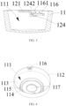
FIG. 1 is a perspective view of a preferred embodiment of the ceiling assembly of the present application. -
FIG. 2 is a structural exploded view ofFIG. 1 . -
FIG. 3 is a cross-sectional view ofFIG. 1 . -
FIG. 4 is a perspective view of a ceiling box inFIG. 1 . -
FIG. 5 is a partial structural enlarged view ofFIG. 4 . -
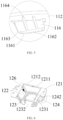
FIG. 6 is a perspective view of a bracket body inFIG. 1 . -
FIG. 7 is a partial structural enlarged view ofFIG. 6 . -
FIG. 8 is a perspective view of a suspension assembly installed on the ceiling assembly. -
FIG. 9 is a cross-sectional view ofFIG. 8 . -
FIG. 10 is an exploded view ofFIG. 8 . -
FIG. 11 is a perspective view of a preferred embodiment of the fan lamp of the present application. - In order to make objects, technical solutions and advantages of the present application clearer, the present application is described in detail below in connection with the accompanying drawings and specific embodiments.
- Herein, it is to be noted that, in order to avoid obscuring the present application due to unnecessary details, only structures and/or processing steps closely related to the embodiments of the present application are shown in the accompanying drawings, and other details not closely related to the present application are omitted.
- In addition, it is also to be noted that the terms "include", "comprise", or any other variant thereof are intended to cover non-exclusive inclusion, such that a process, method, article or apparatus including a set of elements includes not only those elements, but also other elements that are not explicitly listed, or also include elements that are inherent to such process, method, article, or apparatus.
- Referring to
FIG. 1 to FIG. 9 , in which aceiling assembly 1 for installation of afan lamp 100 provided by the present application is illustrated. Theceiling assembly 1 includes abracket body 12 and aceiling box 11, thebracket body 12 and theceiling box 11 are detachably connected, and theceiling box 11 is installed on an installation base through thebracket body 12. The installation base is used for hanging thefan lamp 100, for example, the installation base may be a ceiling of a house or the like. By setting the detachable connection between thebracket body 12 and theceiling box 11 to replace a threadedly fixed connection between thebracket body 12 and theceiling box 11 in the prior art, the installation process is simplified, the installation cost is reduced, and processes for installing and disassembling thefan lamp 100 having theceiling assembly 1 is convenient and quick, and the installation and disassembly can be realized by a single person, which is time-saving and labor-saving, and highly efficient and safe. - Referring to
FIG. 4 to FIG. 6 , and in conjunction withFIG. 1 to FIG. 3 , as illustrated in these figures, theceiling box 11 has aninstallation cavity 111, and thebracket body 12 is housed in theinstallation cavity 111, so as to reduce a space occupied by thebracket body 12 and to improve the structural compactness of thefan lamp 100. Further, theinstallation cavity 111 of theceiling box 11 may also accommodate some functional components of thefan lamp 100, such as a drive assembly, a power supply assembly, asafety rope assembly 5, aterminal assembly 6, and the like, so as to better utilize the space of theceiling box 11 and to improve a structural compactness and aesthetic appearance of thefan lamp 100. - Specifically, the
ceiling box 11 includes a firstannular part 112 and a truncatedconical part 113 disposed below the firstannular part 112, and the firstannular part 112 and the truncatedconical part 113 enclose to form theinstallation cavity 111. The truncatedconical part 113 includes a first end and a second end, the first end and the second end are parallel to each other, and a cross-sectional area of the first end in a horizontal direction is larger than a cross-sectional area of the second end in the horizontal direction. A plane at which a top of the firstannular part 112 is located is higher than or coplanar with a plane at which theinstallation part 121 of thebracket body 12 is located, so that thebracket body 12 is completely accommodated inside theceiling box 11, and the structural compactness and aesthetics of appearance of thefan lamp 100 are improved. A bottom of the firstannular part 112 is connected to the first end, so as to increase a volume of theinstallation cavity 111 of theceiling box 11. A side of the second end toward the first end extends toward a position close to the first end to form a secondannular part 114 and a thirdannular part 115 that have a same center of circle, a diameter of the secondannular part 114 is smaller than a diameter of the thirdannular part 115, and a height of the secondannular part 114 in a vertical direction is lower than a height of the thirdannular part 115 in the vertical direction. Thebracket body 12 is housed within theinstallation cavity 111, and abase plate 123 of thebracket body 12 is located over the secondannular part 114, and asidewall 122 of thebracket body 12 abuts an inner wall of the thirdannular part 115, so as to limit and fix thebracket body 12 in theinstallation cavity 111 of theceiling box 11, thereby limiting a degree of freedom of thebracket body 12 in the horizontal direction, and improving the connection stability of theceiling assembly 1. - A first connecting
part 116 is provided on an inner wall of the firstannular part 112 of theceiling box 11, a second connectingpart 124 is provided on thebracket body 12 at a position corresponding to the first connectingpart 116, the first connectingpart 116 and the second connectingpart 124 are detachably connected, and a first guidingpart 1161 and ajoint part 1162 are provided on a connecting surface of the first connectingpart 116 corresponding to the second connectingpart 124. The first guidingpart 1161 is disposed to be inclined, preferably, the first guidingpart 1161 is an inclined bevel, and an end of the first guidingpart 1161 away from thejoint part 1162 is aguiding end 1163, and a cross-sectional area, along the height direction, of the first guidingpart 1161 at either one position is positively related to a spacing distance between the said either one position of the first guidingpart 1161 and the guidingend 1163 of the first connectingpart 116. By providing the first guidingpart 1161, the second connectingpart 124 is made to slide quickly along the first guidingpart 1161 and onto a connecting surface located below the first connectingpart 116, so that the first connectingpart 116 and the second connectingpart 124 are guided to be smoothly joined, which facilitates the detachable connection of the first connectingpart 116 and the second connectingpart 124. Thejoint part 1162 is connected to an end of the first connectingpart 116 away from theguiding end 1163, and a width of thejoint part 1162 in the horizontal direction is larger than a width of the first guidingpart 1161 in the horizontal direction, so as to increase a tightness of the joint between the first connectingpart 116 and the second connectingpart 124. Preferably, thejoint part 1162 is provided horizontally, of course, thejoint part 1162 may also be provided with other structures that match the second connectingpart 124, which is not limited in the present application. By disposing thejoint part 1162 to make the first connectingpart 116 and the second connectingpart 124 be tightly connected, a gravity of theceiling box 11 itself is utilized to compact the first connectingpart 116 and the second connectingpart 124, so as to improve a stability of the connection between theceiling box 11 and thebracket body 12. - Further, a reinforcing
rib 1164 is disposed on a side of the first connectingpart 116 away from the connecting surface, and the reinforcingrib 1164 is provided to play a role in positioning installation and providing a stable support for the first connectingpart 116, so that the first connectingpart 116 and the second connectingpart 124 realize a positioning connection of theceiling assembly 1, while increasing a structural strength of the first connectingpart 116, and improving a connection firmness of theceiling assembly 1. - Referring to
FIG. 6 to FIG. 7 , and in conjunction withFIG. 1 to FIG. 3 , as illustrated therein, thebracket body 12 includes aninstallation part 121, asidewall 122, and a bottom wall, theinstallation part 121 is connected to the installation base, thesidewall 122 is connected to theinstallation part 121 and the bottom wall, and the bottom wall is connected to the secondannular part 114 of theceiling box 11. In an optional embodiment, thebracket body 12 may be an integrally-formed stamped structure, so that the structural strength of thebracket body 12 is enhanced, and connection fracture of thebracket body 12 can be avoided. Theinstallation part 121 is provided with one or more first fixing hole, and a fastener such as a bolt passes through the first fixing hole and is fixedly connected to the installation base, and anaccommodation space 126 is formed between thesidewall 122, an installation wall and the bottom wall of thebracket body 12, theaccommodation space 126 is used to accommodate components such as asuspension assembly 2, a driving assembly of thefan lamp 100, or the like, so as to increase the structural compactness and aesthetics of thefan lamp 100. - The second connecting
part 124 is provided below theinstallation part 121 of thebracket body 12, i.e., there exists a first height difference along the height direction between theinstallation part 121 and the second connectingpart 124 to form a yieldingspace 125 on thebracket body 12, and facilitate a rotational snap connection of the first connectingpart 116 on theceiling box 11 and the second connectingpart 124, meanwhile, the first connectingpart 116 and the second connectingpart 124 are both accommodated in theinstallation cavity 111 of theceiling box 11 to fully utilize an internal space of theceiling box 11 and improve the aesthetics of appearance of thefan lamp 100. - Further, the second connecting
part 124 includes a second guidingpart 1241 and alimiting part 1242, thelimiting part 1242 and the second guidingpart 1241 are located at two ends of the second connectingpart 124, and an extension direction of thelimiting part 1242 is opposite to an extension direction of the second guidingpart 1241. In an optional embodiment, thesecond guide part 1241 extends obliquely and downwardly to form a beveled guiding area, so as to guide the smooth joint between the first connectingpart 116 and the second connectingpart 124, and to reduce a fit accuracy requirement of the first connectingpart 116 with the second connectingpart 124. The limitingpart 1242 extends upwardly and is fixedly connected with theinstallation part 121 and the second connectingpart 124, so as to limit and stop the first connectingpart 116, prevent the first connectingpart 116 from sliding out of the second connectingpart 124, thereby realizing the effect of anti-detachment, and improving the connection stability of theceiling assembly 1. - In an optional embodiment, an amount of the first connecting
parts 116 is multiple, a plurality of first connectingparts 116 are uniformly arranged at a same circumference of an inner wall of theceiling box 11. An amount of the second connectingparts 124 is multiple, and is the same as the amount of the first connectingparts 116, and a plurality of second connectingparts 124 are uniformly arranged at a same circumference of thebracket body 12. Preferably, two first connectingparts 116 are provided, and the two first connectingparts 116 are mirroring configured, and correspondingly, two second connectingparts 124 are also provided, and the two second connectingparts 124 are also mirroring configured. By mirroring configuration of the first connectingparts 116 and the second connectingparts 124, when theceiling box 11 is rotated in a first direction, the two first connectingparts 116 and the two second connectingparts 124 realize a matching connection between theceiling box 11 and thebracket body 12 through the guiding function of thefirst guiding part 1161 and thesecond guiding part 1241, so as to improve the stability of the connection of theceiling assembly 1. When theceiling box 11 is rotated in a second direction opposite to the first direction, the two first connectingparts 116 and the two second connectingparts 124 are both slid in a direction away from each other to realize the disassembly of theceiling box 11 and thebracket body 12. - In another optional embodiment, the
installation part 121 of thebracket body 12 is provided with a first protrudingpart 1211 and a secondprotruding part 1212, the first protrudingpart 1211 and the second protrudingpart 1212 are provided to face each other, and the first protrudingpart 1211 and the second protrudingpart 1212 may be connected by sliding connection. Through the sliding connection of the first protrudingpart 1211 and the second protrudingpart 1212, the strength of thebracket body 12 can be improved while a volume of thebracket body 12 can be adjusted, thereby facilitating the installation of thebracket body 12. - Referring to
FIG. 8 to FIG. 10 , theceiling box 11 is provided with afirst installation hole 117, thebracket body 12 is provided with asecond installation hole 1231, thesecond installation hole 1231 is in spatial communication with theaccommodation space 126, and thesuspension assembly 2 passes through thefirst installation hole 117 and thesecond installation hole 1231 and is at least partially housed within theceiling assembly 1 to realize the suspension installation of thefan lamp 100. - Specifically, the
suspension assembly 2 includes a hangingrod 21 and a hangingball 22, and the hangingrod 21 and the hangingball 22 are detachably connected by threads, which is convenient for the installation and disassembly of the hangingrod 21 and the hangingball 22, and convenient for the maintenance of thefan lamp 100. Further, in order to prevent the hangingrod 21 from detaching from the hangingball 22, the hangingrod 21 and the hangingball 22 may also be locked by fasteners such as screws in an optional embodiment to achieve fixation between the hangingrod 21 and the hangingball 22. - The hanging
ball 22 passes through thefirst installation hole 117 and thesecond installation hole 1231, and is located in theaccommodation space 126 and clamped in thesecond installation hole 1231, and the hangingrod 21 may be connected to a part of the hangingball 22 that extends out of theaccommodation space 126, and an end of the hangingrod 21 away from the hangingball 22 may be connected to ablade assembly 3 and alight source assembly 4 to facilitate the suspension installation of thefan lamp 100. - Preferably, the
base plate 123 is provided with anotch 1232, and thenotch 1232 is connected with thesecond installation hole 1231, and thesuspension assembly 2 is detachably connected with thebracket body 12 through thenotch 1232. When the hangingrod 21 is disassembled from thebracket body 12, the hangingrod 21 is lifted, and moved out of thebracket body 12 from thenotch 1232. When the hangingrod 21 is installed with thebracket body 12, the hangingrod 21 is lifted, and the hangingrod 21 is moved into thebracket body 12 from thenotch 1232, then upon lowering the hangingrod 21, the hangingball 22 is just secured in thesecond installation hole 1231. With such a configuration, the detachable connection between thesuspension assembly 2 and thebracket body 12 is realized, which is convenient for the assembly and disassembly of thefan lamp 100. - In an optional embodiment, a
limit block 7 is further provided between the hangingball 22 and thesecond installation hole 1231, and thelimit block 7 is secured to the upper part of thesecond installation hole 1231 of thebracket body 12 by screw(s). Athird installation hole 71 is provided in thelimit block 7, and optionally, thelimit block 7 is provided with anopening 72 at a position corresponding to thenotch 1232 of thebracket body 12, and theopening 72 is connected to thethird installation hole 71 to facilitate the detachably connection of thesuspension assembly 2 and thebracket body 12. A cross-sectional dimension of the hangingrod 21 is smaller than that of theopening 72 of the limitingblock 7 and that of thenotch 1232 of thebracket body 12, and the cross-sectional dimension of the hangingball 22 is larger than that of theopening 72 of the limitingblock 7 and thenotch 1232 of thebracket body 12. With such a configuration, the hangingrod 21 can enter into the interior of the limitingblock 7 and thebracket body 12 from theopening 72 of the limitingblock 7 and thenotch 1232 of thebracket body 12, and make the hangingball 22 be located above the limitingblock 7. In this case, under an effect of gravity, the hangingball 22 closely abuts an upper end surface of the limitingblock 7 and subjected to a limiting effect of the limitingblock 7, so that the hangingrod 21 and the fan assembly hanging installed through the hangingrod 21 are hanging installed on thebracket body 12. - In order to improve the stability of the support of the limiting
block 7 to the hangingball 22, the limitingblock 7 in the embodiment of the present application has an inclined or a curved support surface, and accordingly, the outer side surface of the hangingball 22 has an inclined or a curved surface. In this way, when the hangingball 22 is limited by the limitingblock 7, the outer side surface of the hangingball 22 closely fits the support surface of the limitingblock 7, thereby increasing a contact area between the hangingball 22 and the limitingblock 7, meanwhile, the acting force on the outer side surface of the hangingball 22 applied by the support surface can be decomposed into an axial force and a radial force, the axial force can counteract an effect of gravity of the fan assembly, and the radial force can prevent the hangingball 22 from moving and shifting with respect to the limitingblock 7, so as to ensure the stability of the support for the hangingball 22. - Referring to
FIG. 11 , the present application provides a preferred embodiment of thefan lamp 100, which includes thesuspension assembly 2, theblade assembly 3, thelight source assembly 4, and the above-describedceiling assembly 1. Theceiling assembly 1 is detachably connected to thesuspension assembly 2, thesuspension assembly 2 is fixedly connected to theblade assembly 3 and thelight source assembly 4, and thelight source assembly 4 is disposed on a side of theblade assembly 3 away from theceiling assembly 1. Theceiling assembly 1 is used to realize the connection between thefan lamp 100 and the installation base, thereby realizing the installation of thefan lamp 100. Thesuspension assembly 2 can realize the connection between theblade assembly 3 and theceiling assembly 1, i.e., a length of the hangingrod 21 in thesuspension assembly 2 can be set flexibly, and optionally, the hangingrod 21 can adopt a multistage structure, such that the user can adjust the length of the hangingrod 21 according to his or her own needs so as to change the installation height of thefan lamp 100. Theblade assembly 3 can realize a blowing function, and thelight source assembly 4 can perform lighting, thereby making thefan lamp 100 more functional. - When installing the
fan lamp 100, thebracket body 12 in theceiling assembly 1 can first be fixedly installed on the installation base by a fastener such as a screw, theterminal assembly 6 is electrically connected to mains power, and the hangingball 22 in thesuspension assembly 2 is snapped into thefirst installation hole 117 of theceiling box 11, the hangingrod 21 of thesuspension assembly 2 is sequentially connected to theblade assembly 3 and thelight source assembly 4, a functional assembly is placed in theinstallation cavity 111 of theceiling box 11, and after theceiling box 11 is aligned with thebracket body 12, the hangingball 22 of thesuspension assembly 2 enters into thesecond installation hole 1231 of thebracket body 12 through thenotch 1232 on thebase plate 123, and is detachably connected to thebracket body 12. At this time, theceiling box 11 is rotated counterclockwise, the first connectingpart 116 of theceiling box 11 and the second connectingpart 124 of thebracket body 12 are rotationally snapped together under the guiding effect of thefirst guiding part 1161 and thesecond guiding part 1241, and the installation is completed after the first connectingpart 116 of theceiling box 11 contacts the limitingpart 1242 on thebracket body 12. When it is necessary to disassemble thefan lamp 100, theceiling box 11 is first lifted, and then rotated clockwise so that the first connectingpart 116 of theceiling box 11 is separated from the second connectingpart 124 of thebracket body 12, and then thesuspension assembly 2 is pulled out of thesecond installation hole 1231 from thenotch 1232 of thebase plate 123. Thefan lamp 100 can be installed and disassembled by a single person, which is time-saving and labor-saving, and is efficient and safe. - In summary, the
ceiling assembly 1 of the present application has a simple structure, an aesthetically pleasing appearance, and is detachably connected by means of a rotary connection, the installation process is simplified, the installation cost is reduced, and the installation is convenient and fast, so that thefan lamp 100 having theceiling assembly 1 can be installed and disassembled by a single person, which saves time and labor, and is efficient and safe. In addition, the present application makes good use of the space of theceiling box 11 and improves the aesthetics of appearance of thefan lamp 100 by disposing the connecting part of theceiling assembly 1 in theinstallation cavity 111 of theceiling box 11. - The above embodiments are only used to illustrate the technical solutions of the present application, and are not intended to limit the present application, although the present application has been described in detail with reference to the preferred embodiments, a person of ordinary skill in the art should understand that, modifications or equivalent substitutions can be made to the technical solutions of the present application, without departing from the spirit and scope of the technical solutions of the present application.
Claims (10)
- A ceiling assembly, configured for an installation of a fan lamp, and comprising: a bracket body and a ceiling box, wherein the ceiling box has an installation cavity, and the bracket body is housed in the installation cavity, the ceiling box is provided with a first connecting part, the bracket body is provided with a second connecting part at a position corresponding to the first connecting part, the first connecting part is detachably connected with the second connecting part, and the first connecting part is provided with a first guiding part on a connecting surface thereof corresponding to the second connecting part.
- The ceiling assembly according to claim 1, wherein the first guiding part is inclined, and a cross-sectional area, along a height direction, at either one position of the first guiding part is positively related to a spacing distance between the either one position of the first guiding part and a guiding end of the first connecting part.
- The ceiling assembly according to claim 1, wherein a reinforcing rib is provided on a side of the first connecting part away from the connecting surface.
- The ceiling assembly according to claim 1, wherein two first connecting parts are provided, and the two first connecting parts are provided in a mirroring-configuration.
- The ceiling assembly according to claim 1, wherein the bracket body further comprises an installation part, the installation part is connected to an installation base, and there is a first height difference between the installation part and the second connecting part along a height direction.
- The ceiling assembly according to claim 5, wherein the second connecting part comprises a second guiding part and a limiting part, the limiting part and the second guiding part are respectively located at two ends of the second connecting part, and an extension direction of the limiting part is opposite to an extension direction of the second guiding part.
- The ceiling assembly according to claim 6, wherein the limiting part is fixedly connected with the installation part and the second connecting part.
- The ceiling assembly according to claim 1, wherein the ceiling box is provided with a first installation hole, the bracket body is provided with a second installation hole, and a suspension assembly passes through the first installation hole and the second installation hole and is at least partially housed within the ceiling assembly.
- The ceiling assembly according to claim 8, wherein the bracket body further comprises a base plate, the base plate is provided with a notch, the notch is connected to the second installation hole, and the suspension assembly is detachably connected to the bracket body through the notch.
- A fan lamp, comprising: a suspension assembly, a blade assembly, a light source assembly, and a ceiling assembly according to any one of claims 1-9, wherein the ceiling assembly is detachably connected to the suspension assembly, the suspension assembly is fixedly connected to the blade assembly and the light source assembly, and the light source assembly is disposed on a side of the blade assembly away from the ceiling assembly.
Applications Claiming Priority (3)
| Application Number | Priority Date | Filing Date | Title |
|---|---|---|---|
| CN202122567464.9U CN216342927U (en) | 2021-10-25 | 2021-10-25 | Ceiling assembly and fan lamp |
| CN202111240826.1A CN113757150B (en) | 2021-10-25 | 2021-10-25 | Ceiling mount components and fan lights |
| PCT/CN2022/126641 WO2023071928A1 (en) | 2021-10-25 | 2022-10-21 | Ceiling assembly and fan lamp |
Publications (2)
| Publication Number | Publication Date |
|---|---|
| EP4414561A1 true EP4414561A1 (en) | 2024-08-14 |
| EP4414561A4 EP4414561A4 (en) | 2025-01-22 |
Family
ID=86160315
Family Applications (1)
| Application Number | Title | Priority Date | Filing Date |
|---|---|---|---|
| EP22885805.6A Pending EP4414561A4 (en) | 2021-10-25 | 2022-10-21 | CEILING AND FAN LIGHT SET |
Country Status (3)
| Country | Link |
|---|---|
| US (2) | US12523369B2 (en) |
| EP (1) | EP4414561A4 (en) |
| WO (1) | WO2023071928A1 (en) |
Family Cites Families (12)
| Publication number | Priority date | Publication date | Assignee | Title |
|---|---|---|---|---|
| US20030189151A1 (en) * | 2002-04-03 | 2003-10-09 | Hsing Cheng Ming | Apparatus for mounting shroud to ceiling bracket and method of making same |
| US8215920B2 (en) * | 2009-06-29 | 2012-07-10 | Criner Jerry D | Ceiling fan |
| US20110031368A1 (en) * | 2009-08-07 | 2011-02-10 | Air Cool Industrial Co., Ltd | Hanger assembly for ceiling fan |
| GB2484698B (en) * | 2010-10-20 | 2016-12-14 | Greenwood Air Man Ltd | Fan cover locating mechanism |
| CN207179441U (en) * | 2017-08-16 | 2018-04-03 | 南京勤绿光电科技有限公司 | A kind of Novel ceiling lamp ceiling box and lighting mechanism |
| IL258194B (en) * | 2018-03-18 | 2020-08-31 | Yuval Shimon Gorali | A mounting apparatus for a ceiling fan |
| CN210662556U (en) * | 2019-10-09 | 2020-06-02 | 青岛亿联客信息技术有限公司 | Ceiling fan |
| CN211925554U (en) * | 2020-05-22 | 2020-11-13 | 中山市百润照明电器有限公司 | Casual Ceiling Lamp |
| CN113294367A (en) * | 2021-06-30 | 2021-08-24 | 欧普照明股份有限公司 | Fan lamp |
| CN113757150B (en) * | 2021-10-25 | 2026-04-28 | 欧普照明股份有限公司 | Ceiling mount components and fan lights |
| CN216342927U (en) * | 2021-10-25 | 2022-04-19 | 欧普照明股份有限公司 | Ceiling assembly and fan lamp |
| CN217926375U (en) * | 2022-08-04 | 2022-11-29 | 佛山市启正电气有限公司 | Hanging clock mounting structure convenient to disassemble and application product thereof |
-
2022
- 2022-10-21 EP EP22885805.6A patent/EP4414561A4/en active Pending
- 2022-10-21 WO PCT/CN2022/126641 patent/WO2023071928A1/en not_active Ceased
-
2024
- 2024-04-24 US US18/645,347 patent/US12523369B2/en active Active
-
2025
- 2025-12-16 US US19/422,395 patent/US20260104162A1/en active Pending
Also Published As
| Publication number | Publication date |
|---|---|
| WO2023071928A1 (en) | 2023-05-04 |
| US12523369B2 (en) | 2026-01-13 |
| US20260104162A1 (en) | 2026-04-16 |
| EP4414561A4 (en) | 2025-01-22 |
| US20240344677A1 (en) | 2024-10-17 |
Similar Documents
| Publication | Publication Date | Title |
|---|---|---|
| US10907806B2 (en) | Lighting fixture with multiple configurations for different junction box configurations | |
| US4424554A (en) | Ceiling fixture with improved mounting means | |
| CA2185201C (en) | Canopy luminaire | |
| US7866843B2 (en) | Corner mounted light fixture | |
| KR101557329B1 (en) | Kickstand of furniture | |
| US12523369B2 (en) | Ceiling assembly and fan lamp | |
| CN216342927U (en) | Ceiling assembly and fan lamp | |
| US20100208476A1 (en) | Light Fixture Having Socket Track Assemblies with Detachable Row Aligner | |
| KR101941663B1 (en) | Mode switching dual lighting fixtures | |
| KR102404221B1 (en) | Lighting apparatus attaching on ceiling | |
| CN113757150B (en) | Ceiling mount components and fan lights | |
| CN112204304A (en) | Light fitting for attaching a ceiling lamp to a ceiling | |
| KR101096658B1 (en) | Lamp lighting equipment | |
| US7150544B2 (en) | Leveler for light assembly | |
| CN214198400U (en) | Ceiling device and chandelier having the same | |
| US5115385A (en) | Shaped lamp shade | |
| CN103090519A (en) | Air interchanger mounting structure | |
| KR20230001981U (en) | Apparatus for lighting and apparatus for connecting power supply | |
| US20150062906A1 (en) | Portable framing projector | |
| CN218268718U (en) | A liftable lamp | |
| CN219264146U (en) | Suspended ceiling fixing device for installing suspended wire lamp without top plate | |
| CN211260504U (en) | LED projecting lamp convenient to equipment | |
| CN214580554U (en) | Camping lamp | |
| CN223216193U (en) | Rotary drawing type LED kitchen and bathroom lamp | |
| CN216952758U (en) | LED wall lamp |
Legal Events
| Date | Code | Title | Description |
|---|---|---|---|
| STAA | Information on the status of an ep patent application or granted ep patent |
Free format text: STATUS: THE INTERNATIONAL PUBLICATION HAS BEEN MADE |
|
| PUAI | Public reference made under article 153(3) epc to a published international application that has entered the european phase |
Free format text: ORIGINAL CODE: 0009012 |
|
| STAA | Information on the status of an ep patent application or granted ep patent |
Free format text: STATUS: REQUEST FOR EXAMINATION WAS MADE |
|
| 17P | Request for examination filed |
Effective date: 20240424 |
|
| AK | Designated contracting states |
Kind code of ref document: A1 Designated state(s): AL AT BE BG CH CY CZ DE DK EE ES FI FR GB GR HR HU IE IS IT LI LT LU LV MC ME MK MT NL NO PL PT RO RS SE SI SK SM TR |
|
| REG | Reference to a national code |
Ref country code: DE Ref legal event code: R079 Free format text: PREVIOUS MAIN CLASS: F04D0029640000 Ipc: F04D0029600000 |
|
| A4 | Supplementary search report drawn up and despatched |
Effective date: 20250102 |
|
| RIC1 | Information provided on ipc code assigned before grant |
Ipc: F21V 33/00 20060101ALI20241218BHEP Ipc: F21V 21/03 20060101ALI20241218BHEP Ipc: F04D 25/08 20060101ALI20241218BHEP Ipc: F04D 29/60 20060101AFI20241218BHEP |
|
| DAV | Request for validation of the european patent (deleted) | ||
| DAX | Request for extension of the european patent (deleted) |