EP4414497A1 - Ironing board - Google Patents
Ironing board Download PDFInfo
- Publication number
- EP4414497A1 EP4414497A1 EP24020054.3A EP24020054A EP4414497A1 EP 4414497 A1 EP4414497 A1 EP 4414497A1 EP 24020054 A EP24020054 A EP 24020054A EP 4414497 A1 EP4414497 A1 EP 4414497A1
- Authority
- EP
- European Patent Office
- Prior art keywords
- formation
- leg
- formations
- foot
- connector
- Prior art date
- Legal status (The legal status is an assumption and is not a legal conclusion. Google has not performed a legal analysis and makes no representation as to the accuracy of the status listed.)
- Pending
Links
Images




Classifications
-
- D—TEXTILES; PAPER
- D06—TREATMENT OF TEXTILES OR THE LIKE; LAUNDERING; FLEXIBLE MATERIALS NOT OTHERWISE PROVIDED FOR
- D06F—LAUNDERING, DRYING, IRONING, PRESSING OR FOLDING TEXTILE ARTICLES
- D06F81/00—Ironing boards
- D06F81/02—Ironing boards with collapsible underframe
Definitions
- the present invention relates to an ironing board.
- Conventional ironing boards typically comprise a one piece board, tapered at one end, to which is attached a pair of collapsible legs that permit the ironing board to be converted from a collapsed state, suitable for storage, to a deployed state, suitable for ironing.
- the two legs are pivotally attached to one another about half way down their respective lengths.
- An end of one leg is pivotally mounted to the underside of the board at a fixed position, towards one end of the board.
- An end of the other leg is slidably and pivotally mounted towards the opposite end of the underside of the board so that the mounting point can slide from the opposite end of the board towards the position at which the other leg is pivotally mounted.
- Means are provided to lock the sliding pivot in selected positions along the board.
- the sliding mount enables the legs of the board to be folded together and towards the board to facilitate storage of the board and, when the board is in use, the height of the board to be adjusted.
- Distal ends of the legs typically are provided with ferrules or other such non-slip feet for resting on a support surface.
- the present invention seeks to provide an improved ironing board, a kit of parts for an ironing board and method of constructing an ironing board.
- an ironing board comprising an elongate board which locates two leg formations that are pivotally attached to one another to reside either in a first, storage orientation in which the leg formations lie parallel with an underside of the board or in a second, deployed orientation in which the leg formations are inclined relative to the board and relative to one another, at least a first of the two leg formations comprising a distal end region adapted to receive and support a connector which, in use, receives and locates a first foot formation whereby an end of the first foot formation may rest on a support surface when in the deployed orientation.
- the invention provides also a kit of parts for an ironing board, said kit of parts comprising a board having two leg formations as recited in the preceding paragraph, a connector and at least one said first foot formation.
- the kit may comprise a connector pre-secured to either the first leg formation or the foot formation of the first leg formation.
- the kit may comprise a connector for subsequent attachment to each of the first leg formation and said first foot formation.
- the distal end of the or each foot formation preferably is provided with a non-slip foot for resting on a support surface.
- the connector may provide at least one connection formation for receiving an end of part of the first leg formation and at least one connection formation for receiving a said first foot formation.
- at least the first leg formation may comprise two elongate members each adapted to be received by respective connection formations defined by the connector.
- the connector comprises a pair of connection formations each to receive one of a pair of first foot formations.
- a first foot formation may provide a single foot region for contact with a support surface.
- a single foot formation may support two foot regions that are spaced apart in a direction perpendicular to the length of the elongate board.
- the second of the two leg formations may comprise a distal end region adapted to receive and support a connector which, in use, receives and locates a second foot formation whereby an end of the second leg formation may rest on a support surface when in the deployed orientation.
- the second leg formation may comprise an integrally formed foot formation.
- One leg formation may comprise a pair of elongate members which at least in part extend parallel with one another when in the storage orientation.
- the other leg formation may comprises at least one elongate member that lies parallel with said parallel parts of the pair of elongate members of the said one leg formation when in the storage orientation.
- the first leg formation and the first foot formation may comprise tubular elongate members which may be of a circular or other cross-sectional shape to be located securely with connection formations of complementary shape defined by the connector.
- the connection formations may be of circular cross section.
- the ratio of the length to diameter (or maximum cross sectional dimension) of the connection formations is at least 1:1, more preferably at least 1.5:1.
- the first foot formation may comprise a single elongate member that in the assembled condition supports or defines two foot regions that are spaced apart in a direction perpendicular to the length of the elongate board.
- the first foot formation may comprise two elongate members that in the assembled condition each support or define a respective foot region, with the two foot regions being spaced apart in a direction perpendicular to the length of the elongate board.
- the two connection formations of a connector for locating two elongate foot formations preferably have longitudinal axes which are each inclined relative to the longitudinal axis of the or each connection formation that receives an elongate leg formation.
- the longitudinal axis of a connection formation for a foot formation is at an angle of at least 20 degrees, more preferably at least 25 degrees relative to the longitudinal axis of the or each connection formation that receives an elongate leg formation.
- a preferred angle is in the range 20 to 60 degrees and more preferably in the range 25 to 55 degrees.
- the inclined connection formations for locating the first foot formations preferably are angled relative to one another such that their longitudinal axes diverge from one another as considered in a direction from the other connection formation(s) of the connector.
- the elongate foot formations for said inclined connection formations are of a linear shape.
- the elongate members of the first and second leg formations typically may be of metallic material and more typically may be of a tubular type and of circular cross-section.
- the connector also may be of metallic material but preferably is of a polymeric material, such as nylon 6 or other thermoplastic polyamide or an acetal based mineral, and which defines connector sockets that frictionally engage with a leg formation and a foot formation.
- a connection formation of the connector may be in the form of a socket to receive a leg formation or foot formation.
- a connection formation of the connector may be in the form of an insert, such as a stud formation, which is received in the bore of a tubular end of a tubular leg formation or foot formation.
- a connector may comprise at least one said socket and at least one said insert.
- the bore of at least one connection formation in the form of a socket may be provided with ribs that become deformed when an end of a leg formation or foot formation is inserted, thereby to resist subsequent withdrawal of the elongate member and also to accommodate any small variations in size and shape of the elongate member or connector.
- the outer, typically cylindrical, surface of the insert may be provided with ribs to resist subsequent withdrawal of the elongate member and also to accommodate any small variations in size and shape of the elongate member or connector.
- the ribs may extend in a direction parallel with the length of a socket or insert or may extend around said longitudinal axis, for example, either as a plurality of ring shaped ribs.
- a rib may be of a spiral shape thereby assisting the insertion of an elongate member by a twisting action.
- An end of an elongate leg formation for securing to a connector and or an end of a foot formation for securing to the connector may be of metallic material and comprise a surface shaped by a swaging operation to provide an accurately dimensioned surface for engaging with the connector.
- the accurately dimensioned surface will assist in providing a good friction fit with the connector.
- the swaged surface may be an outwardly facing surface of at least one of the tubular leg formation and the tubular foot formation.
- the swaged surface may be an inwardly facing surface of at least one of the tubular leg formation and the tubular foot formation.
- a swaged surface may be of a cylindrical or a frusto conical shape in the case of a tubular leg formation or a tubular foot formation of a circular cross-sectional shape.
- At least an end region of at least one of an elongate leg formation and a foot formation may be of a tubular shape having a noncircular cross section, such as a hexagonal section, and a said end region may define an inwardly or an outwardly facing surface, such as a swaged surface, for securing to the connector.
- the prior art ironing board 10 of Figures 1 and 2 comprises a board which, in known manner, has an underside provided with a first leg formation 14 that comprises a pair of elongate tubular members 15 that are integrally formed with and support a pair of spaced apart foot regions 16, the ironing board 10 further comprising a second leg formation 12 that provides support for a pair of foot regions 13 and are spaced apart in a direction perpendicular to the length of the board,.
- the prior art leg formation 14 is pivotally mounted to the underside of the board at the position X.
- the other leg formation 12 is pivotally attached to a component that is slidable relative to the length of the board and is securable at a plurality of positions along the length of the board in known manner thereby to enable the angle of the leg formation relative to the underside of the boards to be selectively varied.
- the two leg formations 12, 14 are pivotally secured relative to one another at the position Z.
- the underside of an ironing board 20 in accordance with the present invention is shown in Figure 2 .
- the ironing board 20 comprises a board 21 which provides support for a first leg formation 22 that comprises a pair of elongate tubular members 23 connected together at position P and which are pivotally mounted relative to the board 21 at the fixed position X.
- the ironing board 20 additionally comprises a second leg formation 24 that comprises a pair of elongate tubular members 25 pivotally secured to a carriage 27 that is slidable along part of the length of the board and which is securable in known manner at a selected one of a plurality of positions relative to the length of the board by latch means (not shown).
- the elongate members 25 of the second leg formation comprise end regions 28 that are angled outwards away from one another thereby to define two foot regions 26 for resting on a support surface when the ironing board is in a deployed orientation.
- the parallel sections of the two elongate tubes 25 are positioned either side of the pair of elongate tubular members 23 of the first leg formation 22.
- the ironing board 20 of Figure 2 additionally comprises a connector 30 that defines a pair of sockets which receive distal ends 31 of the two elongate leg formation tubes 23.
- the connector 30 is shown in more detail in Figure 3 and, in addition to the sockets 32 that receive distal ends of the elongate members 23, the connector comprises two sockets 34 each to receive a respective one of a pair of foot formations 35.
- the elongate members 23, 25 and the foot formations are formed from metal tubes of a circular cross sectional shape
- Each socket 34 has a longitudinal axis which is inclined at an angle of 30 degrees relative to the direction of the length of the board 21 whereby the foot formations 35 extend outwardly from the connector and diverge from one another to define two foot regions 36 that are spaced apart in a direction perpendicular to the length of the board.
- the foot formations 35 have end regions 38 (see Figure 5 ) that have been shaped by swaging thereby to provide accurately dimensioned surfaces for engagement with the sockets 34 of the connector 30.
- the distal ends 31 of the two leg formation tubes 23 are of a slightly reduced diameter as compared with the remainder of the lengths of the tubes 34 as a result of swaging to provide accurately dimensioned surfaces for engagement with the sockets 32 of the connector 30.
- each of the four sockets 32, 34 has a length in the longitudinal direction of the socket of approximately 1.5 times the diameter of the socket.
- the connector is formed from a material such as nylon and is formed by a moulding operation.
- a material such as nylon
- connectors of other materials and other methods of manufacture may be employed to provide a connector that defines the required sockets for location of at least one foot formation and at least one leg formation.
- the ironing board 20 of Figure 2 is shown in Figure 4 prior to the insertion of the foot formation 35 in the sockets 34 of the connector 30. It will thus be appreciated that the overall length of the ironing board as shown in Figure 4 is substantially less than the length of the assembled board of Figure 2 thereby providing a valuable advantage in respect of space and cost of transportation and storage.
- the pair of straight leg formations 35 may readily be temporarily packaged between ends of the board for transportation and storage.
- Figure 7 shows an assembled ironing board of the present invention with the foot regions 28, 36 each provided with a slip-resistant ferrule 37.
- the ironing board of Figures 2 to 6 comprises two leg formations 23 which each comprise a pair elongate tubular members that extend parallel with one another it will be appreciated that, as exampled by Figure 2 , one of the leg formations may comprise only a single tubular member, at least over the length of the leg formation between the pivot position Z and the mounting position X or Y. Accordingly the present invention teaches that the connector does not necessarily need to comprise the four socket formations 32, 34 as shown in Figure 3 .
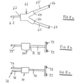
- the connector 61 comprises one socket 62 to receive a single leg formation 63 and two sockets 64 each to receive a foot formation 65 with the outlet sockets 64 being angled relative to the length of the board to provide the spaced apart foot regions 66.
- a connector 70 may comprise a single socket 71 for location of a single foot formation 72 that has a distal end region that defines two spaced apart foot regions 73, as illustrated in Figures 8b in the case of a leg formation 75 having single elongate member or the construction of Figure 8c in which the leg formation 76 comprises two elongate formations 77.
- the ironing board may be supplied to an end user with the connector and foot formation(s) as separate components for assembly to form the construction of Figure 2 , it is envisaged that typically the connector will be preassembled securely at the end of one or each of the leg formations such that the end user is required merely to locate the foot formation(s) in the socket(s) of the connector.
- the present invention teaches that alternatively the connector may be formed integrally with a leg formation.
Landscapes
- Engineering & Computer Science (AREA)
- Textile Engineering (AREA)
- Irons (AREA)
Abstract
Description
- The present invention relates to an ironing board.
- Conventional ironing boards typically comprise a one piece board, tapered at one end, to which is attached a pair of collapsible legs that permit the ironing board to be converted from a collapsed state, suitable for storage, to a deployed state, suitable for ironing. The two legs are pivotally attached to one another about half way down their respective lengths. An end of one leg is pivotally mounted to the underside of the board at a fixed position, towards one end of the board. An end of the other leg is slidably and pivotally mounted towards the opposite end of the underside of the board so that the mounting point can slide from the opposite end of the board towards the position at which the other leg is pivotally mounted. Means are provided to lock the sliding pivot in selected positions along the board. The sliding mount enables the legs of the board to be folded together and towards the board to facilitate storage of the board and, when the board is in use, the height of the board to be adjusted.
- Distal ends of the legs typically are provided with ferrules or other such non-slip feet for resting on a support surface.
- However, a problem with such conventional ironing boards is that, in the collapsed state, a leg at at least one end of the board extends significantly beyond the end of the board. In consequence the length of the collapsed ironing board exceeds that of the board and that extra length presents a disadvantage particularly in respect of space and cost of transportation for delivery to a retail outlet or end user and also space required for storage.
- The present invention seeks to provide an improved ironing board, a kit of parts for an ironing board and method of constructing an ironing board.
- In accordance with one aspect of the present invention there is provided an ironing board comprising an elongate board which locates two leg formations that are pivotally attached to one another to reside either in a first, storage orientation in which the leg formations lie parallel with an underside of the board or in a second, deployed orientation in which the leg formations are inclined relative to the board and relative to one another, at least a first of the two leg formations comprising a distal end region adapted to receive and support a connector which, in use, receives and locates a first foot formation whereby an end of the first foot formation may rest on a support surface when in the deployed orientation.
- The invention provides also a kit of parts for an ironing board, said kit of parts comprising a board having two leg formations as recited in the preceding paragraph, a connector and at least one said first foot formation. The kit may comprise a connector pre-secured to either the first leg formation or the foot formation of the first leg formation. Alternatively the kit may comprise a connector for subsequent attachment to each of the first leg formation and said first foot formation. The distal end of the or each foot formation preferably is provided with a non-slip foot for resting on a support surface.
- In accordance with a further aspect of the present invention there is provided a method of constructing an ironing board, said method comprising use of said kit of parts.
- The connector may provide at least one connection formation for receiving an end of part of the first leg formation and at least one connection formation for receiving a said first foot formation. To assist provision of a stable assembly of the ironing board at least the first leg formation may comprise two elongate members each adapted to be received by respective connection formations defined by the connector.
- In a preferred embodiment the connector comprises a pair of connection formations each to receive one of a pair of first foot formations.
- A first foot formation may provide a single foot region for contact with a support surface. Alternatively a single foot formation may support two foot regions that are spaced apart in a direction perpendicular to the length of the elongate board.
- The second of the two leg formations may comprise a distal end region adapted to receive and support a connector which, in use, receives and locates a second foot formation whereby an end of the second leg formation may rest on a support surface when in the deployed orientation. Alternatively the second leg formation may comprise an integrally formed foot formation.
- One leg formation may comprise a pair of elongate members which at least in part extend parallel with one another when in the storage orientation. The other leg formation may comprises at least one elongate member that lies parallel with said parallel parts of the pair of elongate members of the said one leg formation when in the storage orientation.
- The first leg formation and the first foot formation may comprise tubular elongate members which may be of a circular or other cross-sectional shape to be located securely with connection formations of complementary shape defined by the connector. The connection formations may be of circular cross section. Preferably the ratio of the length to diameter (or maximum cross sectional dimension) of the connection formations is at least 1:1, more preferably at least 1.5:1.
- The first foot formation may comprise a single elongate member that in the assembled condition supports or defines two foot regions that are spaced apart in a direction perpendicular to the length of the elongate board.
- Alternatively the first foot formation may comprise two elongate members that in the assembled condition each support or define a respective foot region, with the two foot regions being spaced apart in a direction perpendicular to the length of the elongate board. The two connection formations of a connector for locating two elongate foot formations preferably have longitudinal axes which are each inclined relative to the longitudinal axis of the or each connection formation that receives an elongate leg formation.
- Preferably the longitudinal axis of a connection formation for a foot formation is at an angle of at least 20 degrees, more preferably at least 25 degrees relative to the longitudinal axis of the or each connection formation that receives an elongate leg formation. A preferred angle is in the
range 20 to 60 degrees and more preferably in therange 25 to 55 degrees. - The inclined connection formations for locating the first foot formations preferably are angled relative to one another such that their longitudinal axes diverge from one another as considered in a direction from the other connection formation(s) of the connector. Preferably the elongate foot formations for said inclined connection formations are of a linear shape.
- The elongate members of the first and second leg formations typically may be of metallic material and more typically may be of a tubular type and of circular cross-section. The connector also may be of metallic material but preferably is of a polymeric material, such as nylon 6 or other thermoplastic polyamide or an acetal based mineral, and which defines connector sockets that frictionally engage with a leg formation and a foot formation.
- A connection formation of the connector may be in the form of a socket to receive a leg formation or foot formation. Alternatively a connection formation of the connector may be in the form of an insert, such as a stud formation, which is received in the bore of a tubular end of a tubular leg formation or foot formation. A connector may comprise at least one said socket and at least one said insert.
- To assist in providing a frictional fit, the bore of at least one connection formation in the form of a socket may be provided with ribs that become deformed when an end of a leg formation or foot formation is inserted, thereby to resist subsequent withdrawal of the elongate member and also to accommodate any small variations in size and shape of the elongate member or connector. Similarly, for a connection formation in the form of an insert for inserting into a tubular end of a leg formation or foot formation the outer, typically cylindrical, surface of the insert may be provided with ribs to resist subsequent withdrawal of the elongate member and also to accommodate any small variations in size and shape of the elongate member or connector.
- The ribs may extend in a direction parallel with the length of a socket or insert or may extend around said longitudinal axis, for example, either as a plurality of ring shaped ribs. Alternatively a rib may be of a spiral shape thereby assisting the insertion of an elongate member by a twisting action.
- An end of an elongate leg formation for securing to a connector and or an end of a foot formation for securing to the connector may be of metallic material and comprise a surface shaped by a swaging operation to provide an accurately dimensioned surface for engaging with the connector. The accurately dimensioned surface will assist in providing a good friction fit with the connector.
- The swaged surface may be an outwardly facing surface of at least one of the tubular leg formation and the tubular foot formation. The swaged surface may be an inwardly facing surface of at least one of the tubular leg formation and the tubular foot formation.
- A swaged surface may be of a cylindrical or a frusto conical shape in the case of a tubular leg formation or a tubular foot formation of a circular cross-sectional shape.
- At least an end region of at least one of an elongate leg formation and a foot formation may be of a tubular shape having a noncircular cross section, such as a hexagonal section, and a said end region may define an inwardly or an outwardly facing surface, such as a swaged surface, for securing to the connector.
- Embodiments of the present invention will now be described by way of example only with reference to the accompanying diagrammatic drawings in which:-
-
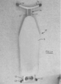
Figures 1a and1b show respectively the upper and under sides of a prior art ironing board when in a collapsed, storage orientation; -
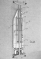
Figure 2 is a view of the underside of an ironing board in accordance with the present invention; -
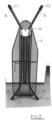
Figure 3 shows two perspective views in opposite directions of the connector of the ironing board ofFigure 2 ; -
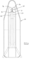
Figure 4 shows the underside of the ironing board ofFigure 2 provided with a connector prior to assembly with a pair of foot formations; -
Figure 5 is an exploded view of a part of the ironing board ofFigure 2 and wherein ends of the foot formations are swaged ends; -
Figure 6 is an exploded view of a part of the ironing board ofFigure 2 and wherein ends of both the foot formations and elongate leg members are swaged ends; -
Figure 7 is a photographic view of the underside of an ironing board of the present invention and wherein the foot formations are provided with non-slip ferules, and -
Figures 8a to 8c show connectors for use with ironing boards having other leg formation and foot formation configurations. - The prior
art ironing board 10 ofFigures 1 and2 comprises a board which, in known manner, has an underside provided with afirst leg formation 14 that comprises a pair of elongatetubular members 15 that are integrally formed with and support a pair of spacedapart foot regions 16, theironing board 10 further comprising asecond leg formation 12 that provides support for a pair offoot regions 13 and are spaced apart in a direction perpendicular to the length of the board,. - The prior
art leg formation 14 is pivotally mounted to the underside of the board at the position X. Theother leg formation 12 is pivotally attached to a component that is slidable relative to the length of the board and is securable at a plurality of positions along the length of the board in known manner thereby to enable the angle of the leg formation relative to the underside of the boards to be selectively varied. - The two
leg formations - The underside of an
ironing board 20 in accordance with the present invention is shown inFigure 2 . The ironingboard 20 comprises aboard 21 which provides support for afirst leg formation 22 that comprises a pair of elongatetubular members 23 connected together at position P and which are pivotally mounted relative to theboard 21 at the fixed position X. - The ironing
board 20 additionally comprises asecond leg formation 24 that comprises a pair of elongatetubular members 25 pivotally secured to acarriage 27 that is slidable along part of the length of the board and which is securable in known manner at a selected one of a plurality of positions relative to the length of the board by latch means (not shown). - The
elongate members 25 of the second leg formation compriseend regions 28 that are angled outwards away from one another thereby to define twofoot regions 26 for resting on a support surface when the ironing board is in a deployed orientation. In this construction the parallel sections of the twoelongate tubes 25 are positioned either side of the pair of elongatetubular members 23 of thefirst leg formation 22. - The ironing
board 20 ofFigure 2 additionally comprises aconnector 30 that defines a pair of sockets which receive distal ends 31 of the two elongateleg formation tubes 23. - The
connector 30 is shown in more detail inFigure 3 and, in addition to thesockets 32 that receive distal ends of theelongate members 23, the connector comprises twosockets 34 each to receive a respective one of a pair offoot formations 35. Theelongate members - Each
socket 34 has a longitudinal axis which is inclined at an angle of 30 degrees relative to the direction of the length of theboard 21 whereby thefoot formations 35 extend outwardly from the connector and diverge from one another to define twofoot regions 36 that are spaced apart in a direction perpendicular to the length of the board. - In this embodiment of the present invention the
foot formations 35 have end regions 38 (seeFigure 5 ) that have been shaped by swaging thereby to provide accurately dimensioned surfaces for engagement with thesockets 34 of theconnector 30. Optionally, as shown inFigure 6 , the distal ends 31 of the twoleg formation tubes 23 are of a slightly reduced diameter as compared with the remainder of the lengths of thetubes 34 as a result of swaging to provide accurately dimensioned surfaces for engagement with thesockets 32 of theconnector 30. - In this embodiment each of the four
sockets - In this embodiment of the invention the connector is formed from a material such as nylon and is formed by a moulding operation. However it will be appreciated that connectors of other materials and other methods of manufacture may be employed to provide a connector that defines the required sockets for location of at least one foot formation and at least one leg formation.
- The ironing
board 20 ofFigure 2 is shown inFigure 4 prior to the insertion of thefoot formation 35 in thesockets 34 of theconnector 30. It will thus be appreciated that the overall length of the ironing board as shown inFigure 4 is substantially less than the length of the assembled board ofFigure 2 thereby providing a valuable advantage in respect of space and cost of transportation and storage. The pair ofstraight leg formations 35 may readily be temporarily packaged between ends of the board for transportation and storage. -
Figure 7 shows an assembled ironing board of the present invention with thefoot regions resistant ferrule 37. - Although the ironing board of
Figures 2 to 6 comprises twoleg formations 23 which each comprise a pair elongate tubular members that extend parallel with one another it will be appreciated that, as exampled byFigure 2 , one of the leg formations may comprise only a single tubular member, at least over the length of the leg formation between the pivot position Z and the mounting position X or Y. Accordingly the present invention teaches that the connector does not necessarily need to comprise the foursocket formations Figure 3 . - Referring to
Figure 8a theconnector 61 comprises onesocket 62 to receive asingle leg formation 63 and twosockets 64 each to receive afoot formation 65 with theoutlet sockets 64 being angled relative to the length of the board to provide the spaced apartfoot regions 66. - In further alternative constructions a
connector 70 may comprise asingle socket 71 for location of asingle foot formation 72 that has a distal end region that defines two spaced apartfoot regions 73, as illustrated inFigures 8b in the case of aleg formation 75 having single elongate member or the construction ofFigure 8c in which theleg formation 76 comprises two elongate formations 77. - Although the ironing board may be supplied to an end user with the connector and foot formation(s) as separate components for assembly to form the construction of
Figure 2 , it is envisaged that typically the connector will be preassembled securely at the end of one or each of the leg formations such that the end user is required merely to locate the foot formation(s) in the socket(s) of the connector. - Although for manufacturing convenience and reduction of cost it is generally advantageous to provide a connector that is an independent component, the present invention teaches that alternatively the connector may be formed integrally with a leg formation.
Claims (15)
- An ironing board (20) comprises an elongate board (21) which locates two leg formations (22, 24) that are pivotally attached to one another to reside either in a first, storage orientation in which the leg formations lie parallel with an underside of the board or in a second, deployed orientation in which the leg formations are inclined relative to the board and relative to one another, at least a first (22) of the two leg formations comprising a distal end region (31) adapted to receive and support a connector which, in use, receives and locates a first foot formation (35) whereby an end of the first foot formation may rest on a support surface when in the deployed orientation.
- An ironing board according to claim 1 wherein at least the first leg formation comprises two elongate members (25) each adapted to be received by respective connection formations (34) defined by the connector and wherein the connector comprises a pair of connection formations each to receive one of a pair of first foot formations.
- An ironing board according to any one of the preceding claims wherein one of the leg formations comprises a pair of elongate members which at least in part extend parallel with one another when in the storage orientation and wherein the other of the leg formations comprises at least one elongate member that lies parallel with said parallel parts of the pair of elongate members of the said one leg formation when in the storage orientation.
- An ironing board according to any one of the preceding claims wherein the first leg formation (22) and the first foot formation (35) comprise tubular elongate members to locate securely with connection formations (32, 34) of complementary shape defined by the connector.
- An ironing board according to claim 4 wherein the connection formations (32, 34) are of circular cross-sectional shape and have a length to diameter ratio of at least 1:1, preferably at least 1.5:1.
- An ironing board according to any one of the preceding claims wherein the first foot formation comprises two elongate members (35) that, in the assembled condition, each support or define a respective foot region (36) with the two foot regions being spaced apart in a direction perpendicular to the length of the elongate board and wherein two connection formations of the connector for locating two elongate foot formations have longitudinal axes which are inclined relative to the longitudinal axes of the or each of the connection formations that receives an end region of an elongate leg formation.
- An ironing board according to claim 6 wherein the longitudinal axis of a connection formation for location with a foot formation is at an angle of at least 20° relative to the longitudinal axis of the or each connection formation that receives an elongate leg formation.
- An ironing board according to claim 7 wherein said angle is in the range 20° to 60°.
- An ironing board according to any one of claims 6 to 8 wherein the inclined connection formations for locating the first foot formation are angled relative to one another such that their longitudinal axes diverge from one another as considered in a direction from the other connection formation(s) of the connector.
- An ironing board according to any one of the preceding claims wherein an end region (38) of the first foot formation (35) defines a swaged surface that is adapted to be received and located by the connector.
- An ironing board according to any one of the preceding claims wherein the distal end region (31) of at least the first (23) of the two leg formations defines a swaged surface that is adapted to receive and support the connector.
- An ironing board according to any one of the preceding claims wherein at least one of the connection formations of the connector is provided with ribs that become deformed when the connector is assembled with a leg formation or foot formation.
- A kit of parts for an ironing board, said kit of parts comprising a board having two leg formations (22, 24), a connector (30) and at least one said first foot formation (35) as recited in any one of the preceding claims.
- A kit according to claim 13 wherein the kit comprises a connector (30) pre-secured to either the first leg formation (22) or the foot formation of the first leg formation (35).
- A method of co0nstructing an ironing board, said method comprising use of a kit of parts according to claim 13 or claim 14.
Applications Claiming Priority (1)
| Application Number | Priority Date | Filing Date | Title |
|---|---|---|---|
| GB2302023.3A GB2627003A (en) | 2023-02-13 | 2023-02-13 | Ironing board |
Publications (1)
| Publication Number | Publication Date |
|---|---|
| EP4414497A1 true EP4414497A1 (en) | 2024-08-14 |
Family
ID=85704384
Family Applications (1)
| Application Number | Title | Priority Date | Filing Date |
|---|---|---|---|
| EP24020054.3A Pending EP4414497A1 (en) | 2023-02-13 | 2024-02-12 | Ironing board |
Country Status (3)
| Country | Link |
|---|---|
| US (1) | US20240271356A1 (en) |
| EP (1) | EP4414497A1 (en) |
| GB (2) | GB2627003A (en) |
Citations (4)
| Publication number | Priority date | Publication date | Assignee | Title |
|---|---|---|---|---|
| JP2000218098A (en) * | 1999-01-27 | 2000-08-08 | Yamazaki Jitsugyo Kk | Ironing board |
| EP1245716A2 (en) * | 2001-03-30 | 2002-10-02 | Vorwerk & Co. Interholding GmbH | Ironing device |
| CN201209220Y (en) * | 2008-04-18 | 2009-03-18 | 何玉莲 | Ironing board foot rest convenient for packaging and transporting |
| CN201276657Y (en) * | 2008-10-17 | 2009-07-22 | 何玉莲 | Ironing board with plug-in type support foot seat |
Family Cites Families (4)
| Publication number | Priority date | Publication date | Assignee | Title |
|---|---|---|---|---|
| US5950337A (en) * | 1998-01-07 | 1999-09-14 | Lehrman; David | Hanging attachment for hanging an ironing board assembly from an upper edge of a door |
| GB2394965B (en) * | 2002-11-04 | 2006-04-12 | Mark Stephen Buckle | A portable, collapsible ironing board |
| GB0916384D0 (en) * | 2009-09-18 | 2009-10-28 | Vale Mill Rochdale Ltd | Ironing board |
| FR2990961B1 (en) * | 2012-05-24 | 2014-05-23 | Seb Sa | IRONING BOARD COMPRISING TWO FEET ARRANGED ACCORDING TO X CONFIGURATION |
-
2023
- 2023-02-13 GB GB2302023.3A patent/GB2627003A/en active Pending
-
2024
- 2024-02-12 EP EP24020054.3A patent/EP4414497A1/en active Pending
- 2024-02-12 GB GB2401930.9A patent/GB2628891B/en active Active
- 2024-02-13 US US18/440,451 patent/US20240271356A1/en not_active Abandoned
Patent Citations (4)
| Publication number | Priority date | Publication date | Assignee | Title |
|---|---|---|---|---|
| JP2000218098A (en) * | 1999-01-27 | 2000-08-08 | Yamazaki Jitsugyo Kk | Ironing board |
| EP1245716A2 (en) * | 2001-03-30 | 2002-10-02 | Vorwerk & Co. Interholding GmbH | Ironing device |
| CN201209220Y (en) * | 2008-04-18 | 2009-03-18 | 何玉莲 | Ironing board foot rest convenient for packaging and transporting |
| CN201276657Y (en) * | 2008-10-17 | 2009-07-22 | 何玉莲 | Ironing board with plug-in type support foot seat |
Also Published As
| Publication number | Publication date |
|---|---|
| GB2627003A (en) | 2024-08-14 |
| US20240271356A1 (en) | 2024-08-15 |
| GB202302023D0 (en) | 2023-03-29 |
| GB2628891B (en) | 2026-06-10 |
| GB2628891A (en) | 2024-10-09 |
| GB202401930D0 (en) | 2024-03-27 |
Similar Documents
| Publication | Publication Date | Title |
|---|---|---|
| US20210085042A1 (en) | Locking mechanism for foldable pole and foldable pole | |
| US6006477A (en) | Umbrella rod structure of multiple tubes | |
| EP1884400A2 (en) | Support device for a child vehicle safety seat | |
| US10603779B2 (en) | Adaptable pole for a pool device | |
| US5367743A (en) | Telescopic handle for luggage carts | |
| US20080029473A1 (en) | Clothes rack available for dustproof jacket | |
| CN101986953A (en) | Cardboard tube connecting structure and chair using the connecting structure | |
| US20060083580A1 (en) | Folding joint arrangement for foldable furniture | |
| US20120025481A1 (en) | Collapsible golf trolley | |
| US5082221A (en) | Symmetrically-actuated adjustable leg assembly | |
| US20200337468A1 (en) | Adjustable support and bed frame having same | |
| US20060051159A1 (en) | Positioning device for a foldable structure | |
| CN101952526A (en) | Union | |
| AU2022373000A1 (en) | Length-adjustable pole | |
| US20240271356A1 (en) | Ironing board | |
| JP5894744B2 (en) | Assembled tent | |
| CN112283221A (en) | Extension tube assembly | |
| US7445398B2 (en) | Coupling spring pin | |
| US12124155B2 (en) | Backdrop stand | |
| EP1120057A1 (en) | Foldable umbrella | |
| CN117916476A (en) | Folding length adjustment mechanism | |
| EP0618375B1 (en) | Connecting mechanism for detachably connecting two members together | |
| US20210169215A1 (en) | Frame and table having structure for reducing vibration | |
| US20140036519A1 (en) | Spiraling support tube | |
| KR102175980B1 (en) | The fixing struture of a multi-step foldable pipe |
Legal Events
| Date | Code | Title | Description |
|---|---|---|---|
| PUAI | Public reference made under article 153(3) epc to a published international application that has entered the european phase |
Free format text: ORIGINAL CODE: 0009012 |
|
| STAA | Information on the status of an ep patent application or granted ep patent |
Free format text: STATUS: THE APPLICATION HAS BEEN PUBLISHED |
|
| AK | Designated contracting states |
Kind code of ref document: A1 Designated state(s): AL AT BE BG CH CY CZ DE DK EE ES FI FR GB GR HR HU IE IS IT LI LT LU LV MC ME MK MT NL NO PL PT RO RS SE SI SK SM TR |
|
| STAA | Information on the status of an ep patent application or granted ep patent |
Free format text: STATUS: REQUEST FOR EXAMINATION WAS MADE |
|
| 17P | Request for examination filed |
Effective date: 20250210 |
|
| GRAP | Despatch of communication of intention to grant a patent |
Free format text: ORIGINAL CODE: EPIDOSNIGR1 |
|
| STAA | Information on the status of an ep patent application or granted ep patent |
Free format text: STATUS: GRANT OF PATENT IS INTENDED |
|
| INTG | Intention to grant announced |
Effective date: 20260309 |
|
| GRAJ | Information related to disapproval of communication of intention to grant by the applicant or resumption of examination proceedings by the epo deleted |
Free format text: ORIGINAL CODE: EPIDOSDIGR1 |
|
| STAA | Information on the status of an ep patent application or granted ep patent |
Free format text: STATUS: REQUEST FOR EXAMINATION WAS MADE |
|
| GRAP | Despatch of communication of intention to grant a patent |
Free format text: ORIGINAL CODE: EPIDOSNIGR1 |
|
| STAA | Information on the status of an ep patent application or granted ep patent |
Free format text: STATUS: GRANT OF PATENT IS INTENDED |
|
| INTC | Intention to grant announced (deleted) | ||
| GRAS | Grant fee paid |
Free format text: ORIGINAL CODE: EPIDOSNIGR3 |
|
| INTG | Intention to grant announced |
Effective date: 20260526 |
|
| GRAJ | Information related to disapproval of communication of intention to grant by the applicant or resumption of examination proceedings by the epo deleted |
Free format text: ORIGINAL CODE: EPIDOSDIGR1 |
|
| GRAL | Information related to payment of fee for publishing/printing deleted |
Free format text: ORIGINAL CODE: EPIDOSDIGR3 |
|
| STAA | Information on the status of an ep patent application or granted ep patent |
Free format text: STATUS: REQUEST FOR EXAMINATION WAS MADE |